uhv gate valve series 10 - banner industries · mm inch iso-f cf-f metric threads ... uhv gate...
TRANSCRIPT
Ordering information
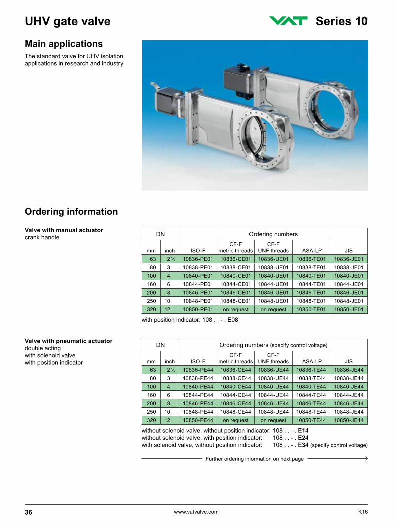
Main applicationsThe standard valve for UHV isolation applications in research and industry
Valve with manual actuatorcrank handle
Valve with pneumatic actuatordouble actingwith solenoid valvewith position indicator
DN Ordering numbers
mm inch ISO-FCF-F
metric threadsCF-F
UNF threads ASA-LP JIS 63 2 ½ 10836-PE01 10836-CE01 10836-UE01 10836-TE01 10836-JE01 80 3 10838-PE01 10838-CE01 10838-UE01 10838-TE01 10838-JE01 100 4 10840-PE01 10840-CE01 10840-UE01 10840-TE01 10840-JE01 160 6 10844-PE01 10844-CE01 10844-UE01 10844-TE01 10844-JE01 200 8 10846-PE01 10846-CE01 10846-UE01 10846-TE01 10846-JE01 250 10 10848-PE01 10848-CE01 10848-UE01 10848-TE01 10848-JE01 320 12 10850-PE01 on request on request 10850-TE01 10850-JE01
DN Ordering numbers (specify control voltage)
mm inch ISO-FCF-F
metric threadsCF-F
UNF threads ASA-LP JIS 63 2 ½ 10836-PE44 10836-CE44 10836-UE44 10836-TE44 10836-JE44 80 3 10838-PE44 10838-CE44 10838-UE44 10838-TE44 10838-JE44 100 4 10840-PE44 10840-CE44 10840-UE44 10840-TE44 10840-JE44 160 6 10844-PE44 10844-CE44 10844-UE44 10844-TE44 10844-JE44 200 8 10846-PE44 10846-CE44 10846-UE44 10846-TE44 10846-JE44 250 10 10848-PE44 10848-CE44 10848-UE44 10848-TE44 10848-JE44 320 12 10850-PE44 on request on request 10850-TE44 10850-JE44
without solenoid valve, without position indicator: 108 . . - . E14without solenoid valve, with position indicator: 108 . . - . E24with solenoid valve, without position indicator: 108 . . - . E34 (specify control voltage)
with position indicator: 108 . . - . E08
Further ordering information on next page
36 www.vatvalve.com K16
UHV gate valve Series 10
DN Ordering numbers (specify control voltage)
mm inch ISO-FCF-F
metric threadsCF-F
UNF threads ASA-LP JIS 63 2 ½ 10836-PE48 10836-CE48 10836-UE48 10836-TE48 10836-JE48 80 3 10838-PE48 10838-CE48 10838-UE48 10838-TE48 10838-JE48 100 4 10840-PE48 10840-CE48 10840-UE48 10840-TE48 10840-JE48 160 6 10844-PE48 10844-CE48 10844-UE48 10844-TE48 10844-JE48 200 8 10846-PE48 10846-CE48 10846-UE48 10846-TE48 10846-JE48 250 10 10848-PE48 10848-CE48 10848-UE48 10848-TE48 10848-JE48 320 12 10850-PE48 on request on request 10850-TE48 10850-JE48
without solenoid valve, with position indicator: 108 . . - . E28
Technical data
Continued Ordering information
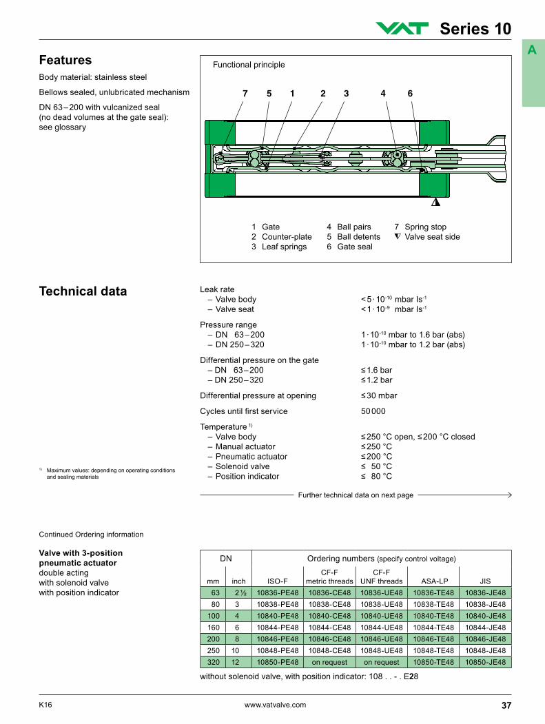
1 Gate 4 Ball pairs 7 Spring stop2 Counter-plate 5 Ball detents Valve seat side3 Leaf springs 6 Gate seal
Leak rate – Valve body < 5 · 10-10 mbar Is-1 – Valve seat < 1 · 10-9 mbar Is-1
Pressure range – DN 63 – 200 1 · 10-10 mbar to 1.6 bar (abs) – DN 250 – 320 1 · 10-10 mbar to 1.2 bar (abs)
Differential pressure on the gate –DN 63–200 ≤1.6bar –DN250–320 ≤1.2bar
Differentialpressureatopening ≤30mbar
Cyclesuntilfirstservice 50000
Temperature 1) –Valvebody ≤250°Copen,≤200°Cclosed –Manualactuator ≤250°C –Pneumaticactuator ≤200°C –Solenoidvalve ≤ 50°C –Positionindicator ≤ 80°C
Valve with 3-position pneumatic actuatordouble actingwith solenoid valvewith position indicator
1) Maximum values: depending on operating conditions and sealing materials
Further technical data on next page
Functional principleFeaturesBody material: stainless steel
Bellows sealed, unlubricated mechanism
DN 63 – 200 with vulcanized seal (no dead volumes at the gate seal): see glossary
37K16 www.vatvalve.com
Series 10A
Continued Technical data
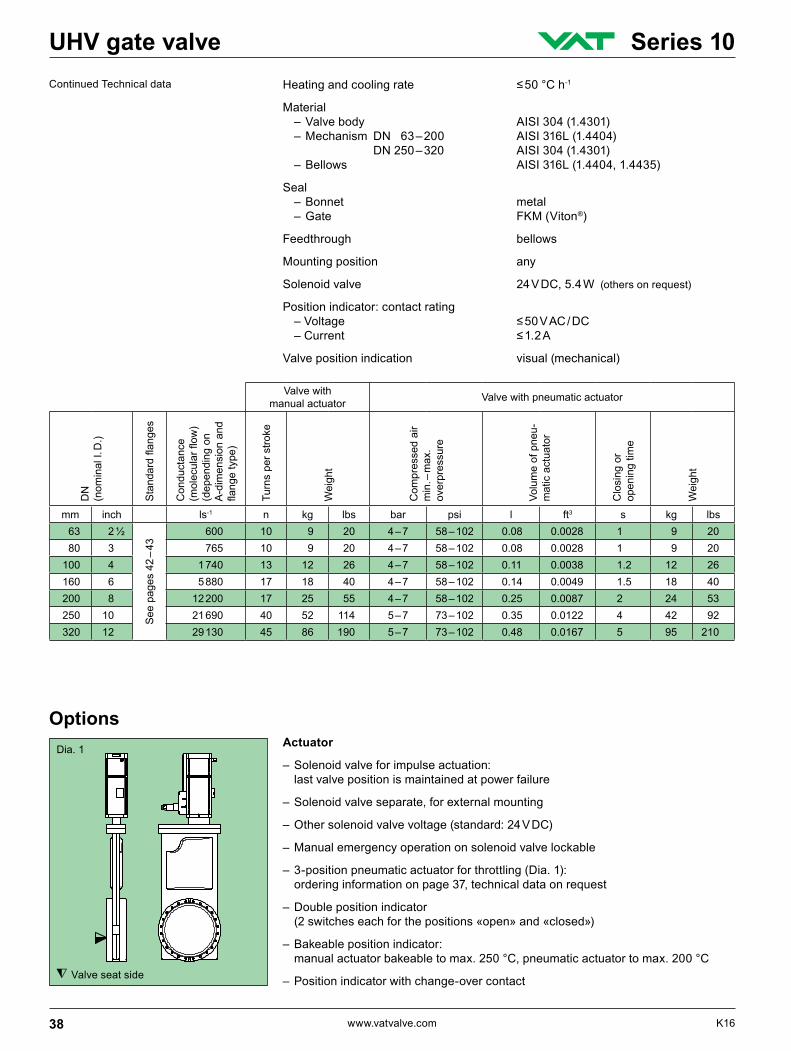
Valve seat side
Dia. 1 Actuator
– Solenoid valve for impulse actuation: last valve position is maintained at power failure
– Solenoid valve separate, for external mounting
– Other solenoid valve voltage (standard: 24 V DC)
– Manual emergency operation on solenoid valve lockable
– 3-position pneumatic actuator for throttling (Dia. 1): ordering information on page 37, technical data on request
– Double position indicator (2 switches each for the positions «open» and «closed»)
– Bakeable position indicator: manualactuatorbakeabletomax.250°C,pneumaticactuatortomax.200°C
– Position indicator with change-over contact
Options
Heatingandcoolingrate ≤50°Ch-1
Material – Valve body AISI 304 (1.4301) – Mechanism DN 63 – 200 AISI 316L (1.4404) DN 250 – 320 AISI 304 (1.4301) – Bellows AISI 316L (1.4404, 1.4435)
Seal – Bonnet metal – Gate FKM (Viton®)
Feedthrough bellows
Mounting position any
Solenoid valve 24 V DC, 5.4 W (others on request)
Position indicator: contact rating –Voltage ≤50VAC/DC –Current ≤1.2A
Valve position indication visual (mechanical)
Valve with manual actuator Valve with pneumatic actuator
DN
(n
omin
al I.
D.)
Standardflanges
Con
duct
ance
(molecularflow
)(d
epen
ding
on
A-d
imen
sion
and
flangetype)
Turn
s pe
r stro
ke
Wei
ght
Com
pres
sed
air
min
. – m
ax.
over
pres
sure
Volu
me
of p
neu-
mat
ic a
ctua
tor
Clo
sing
or
open
ing
time
Wei
ght
mm inch ls-1 n kg lbs bar psi l ft3 s kg lbs63 2 ½
See
pag
es 4
2 –
43
600 10 9 20 4 – 7 58 – 102 0.08 0.0028 1 9 2080 3 765 10 9 20 4 – 7 58 – 102 0.08 0.0028 1 9 20
100 4 1 740 13 12 26 4 – 7 58 – 102 0.11 0.0038 1.2 12 26160 6 5 880 17 18 40 4 – 7 58 – 102 0.14 0.0049 1.5 18 40200 8 12 200 17 25 55 4 – 7 58 – 102 0.25 0.0087 2 24 53250 10 21 690 40 52 114 5 – 7 73 – 102 0.35 0.0122 4 42 92320 12 29 130 45 86 190 5 – 7 73 – 102 0.48 0.0167 5 95 210
38 www.vatvalve.com K16
UHV gate valve Series 10
Valve seat side
Valve seat side
Valve
–Customerspecifiedflangeswith/withoutwatercooling
– Other sealing materials
– O-ring seal in gate (Dia. 2) with DN 63, 100, 160, 200 (standard: vulcanized seal)
– Ports for roughing (by-pass), venting or for gauges (Dia. 3), possible in positions A and B
– Space saving compact version, DN 200 + 250 (Dia. 4)
– Special gate for the installation of various foils
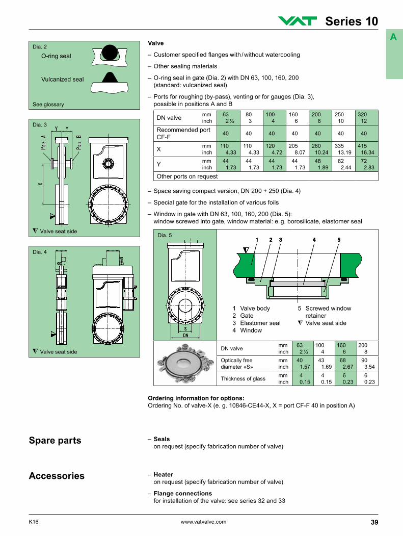
– Window in gate with DN 63, 100, 160, 200 (Dia. 5): window screwed into gate, window material: e. g. borosilicate, elastomer seal
Ordering information for options:Ordering No. of valve-X (e. g. 10846-CE44-X, X = port CF-F 40 in position A)
Dia. 3
Dia. 4
Dia. 2
– Seals on request (specify fabrication number of valve)
Spare parts
– Heater on request (specify fabrication number of valve)
– Flange connections for installation of the valve: see series 32 and 33
Accessories
DN valve mm inch
63 2 ½
80 3
100 4
160 6
200 8
250 10
320 12
Recommended port CF-F 40 40 40 40 40 40 40
X mm inch
110 4.33
110 4.33
120 4.72
205 8.07
260 10.24
335 13.19
415 16.34
Y mm inch
44 1.73
44 1.73
44 1.73
44 1.73
48 1.89
62 2.44
72 2.83
Other ports on request
Dia. 5
1 Valve body 5 Screwed window 2 Gate retainer 3 Elastomer seal Valve seat side 4 Window
DN valve mm inch
63 2 ½
100 4
160 6
200 8
Optically free diameter «S»
mm inch
40 1.57
43 1.69
68 2.67
90 3.54
Thickness of glass mm inch
4 0.15
4 0.15
6 0.23
6 0.23
O-ring seal
Vulcanized seal
See glossary
39K16 www.vatvalve.com
Series 10A
Projection E
DN mm inch
63 2 ½
80 3
100 4
160 6
200 8
250 10
320 12
K mm inch
25.55 1.01
25.55 1.01
25.55 1.01
25.55 1.01
31 1.22
41 1.61
54 2.13
L mm inch
408 16.06
421 16.57
462 18.19
552 21.73
660 25.98
841 33.11
1038 40.87
M mm inch
53 2.09
53 2.09
69 2.72
94.50 3.72
120 4.72
161 6.34
198 7.80
N mm inch
192 7.56
205 8.07
247 9.72
336 13.23
430 16.93
559 22.01
724 28.50
O mm inch
115 4.53
115 4.53
145 5.71
200 7.87
250 9.84
344 13.54
448 17.64
O1 mm inch
104.60 4.12
104.60 4.12
134.60 5.30
184.80 7.28
230 9.06
321 12.64
396 15.59
P mm inch
70 2.76
70 2.76
70 2.76
70 2.76
80 3.15
80 3.15
114 4.49
Q mm inch
112 4.41
112 4.41
142 5.59
192 7.56
350 13.78
450 17.72
560 22.05
S mm inch
11 0.43
11 0.43
9 0.35
25 0.98
38.50 1.52
67 2.64
80 3.15
T mm inch
184 7.24
184 7.24
184 7.24
184 7.24
200 7.87
240 9.45
272 10.71
U mm inch
70 2.76
70 2.76
70 2.76
70 2.76
90 3.54
90 3.54
90 3.54
U1 mm inch
83 3.27
83 3.27
83 3.27
83 3.27
103 4.06
103 4.06
103 4.06
W mm inch
77 3.03
77 3.03
77 3.03
77 3.03
94 3.70
134 5.28
134 5.28
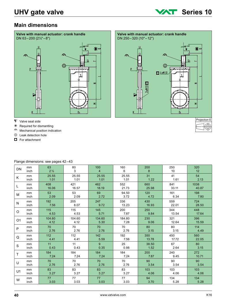
Main dimensionsValve with manual actuator: crank handle DN 250 – 320 (10" – 12")
Valve with manual actuator: crank handle DN 63 – 200 (2½" – 8")
Flange dimensions: see pages 42 –43
Valve seat side g Required for dismantlinge Mechanical position indicationd Leak detection holei For attachment
40 www.vatvalve.com K16
UHV gate valve Series 10
Projection E
DN mm inch
63 2 ½
80 3
100 4
160 6
200 8
250 10
320 12
K mm inch
25.55 1.01
25.55 1.01
25.55 1.01
25.55 1.01
31 1.22
41 1.61
54 2.13
L mm inch
346 13.62
358 14.09
418 16.46
523 20.59
630 24.80
800 31.50
1013 39.88
M mm inch
53 2.09
53 2.09
69 2.72
94.50 3.72
120 4.72
161 6.34
198 7.80
N mm inch
192 7.56
205 8.07
247 9.72
336 13.23
430 16.93
559 22.01
724 28.50
O mm inch
115 4.53
115 4.53
145 5.71
200 7.87
250 9.84
344 13.54
448 17.64
O1 mm inch
104.60 4.12
104.60 4.12
134.60 5.30
184.80 7.28
230 9.06
321 12.64
396 15.59
P mm inch
70 2.76
70 2.76
70 2.76
70 2.76
80 3.15
80 3.15
114 4.49
Q mm inch
112 4.41
112 4.41
142 5.59
192 7.56
350 13.78
450 17.72
560 22.05
S mm inch
11 0.43
11 0.43
9 0.35
25 0.98
38.50 1.52
67 2.64
80 3.15
T mm inch
154 6.06
154 6.06
171 6.73
187 7.36
200 7.87
240 9.45
289 11.38
U mm inch
70 2.76
70 2.76
70 2.76
70 2.76
90 3.54
90 3.54
90 3.54
U1 mm inch
83 3.27
83 3.27
83 3.27
83 3.27
103 4.06
103 4.06
103 4.06
V mm inch
145 5.71
145 5.71
145 5.71
145 5.71
155 6.10
155 6.10
155 6.10
W mm inch
77 3.03
77 3.03
77 3.03
77 3.03
87 3.43
87 3.43
87 3.43
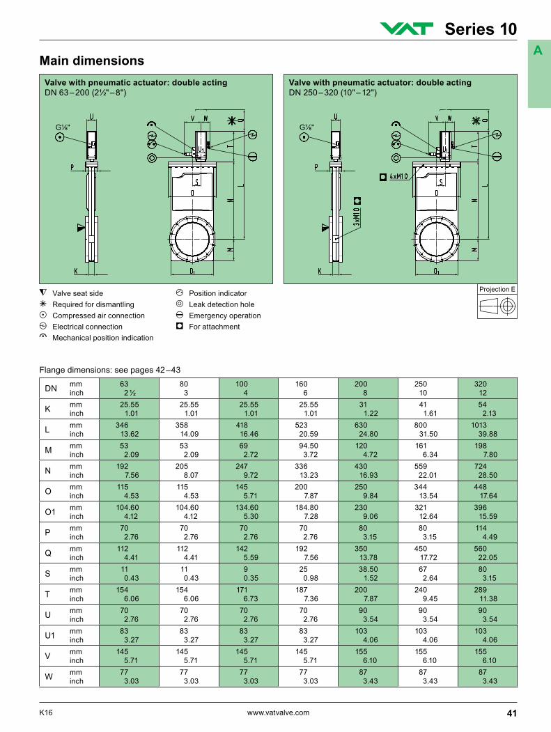
Flange dimensions: see pages 42 –43
Valve seat side f Position indicator g Required for dismantling d Leak detection holeb Compressed air connection h Emergency operationc Electrical connection i For attachmente Mechanical position indication
Main dimensionsValve with pneumatic actuator: double acting DN 250 – 320 (10" – 12")
Valve with pneumatic actuator: double acting DN 63 – 200 (2½" – 8")
41K16 www.vatvalve.com
Series 10A

ISO-F DN 63 – 320 (2½" – 12")
Projection E
DN mm inch
63 2 ½
80 3
100 4
160 6
200 8
250 10
320 12
A mm inch
70 2.76
70 2.76
70 2.76
70 2.76
80 3.15
100 3.94
120 4.72
B mm inch
130 5.12
145 5.71
165 6.50
225 8.86
285 11.22
350 13.78
425 16.73
C mm inch
110 4.33
125 4.92
145 5.71
200 7.87
260 10.24
310 12.20
395 15.55
D mm inch
70 2.76
76 2.99
100 3.94
150 5.91
200 7.87
261 10.28
306 12.05
E × F 4 × M8 8 × M8 8 × M8 8 × M10 12 × M10 12 × M10 12 × M12
G mm inch
13 0.51
13 0.51
13 0.51
13 0.51
15 0.59
15 0.59
18 0.71
H mm inch – 83
3.27 102 4.02
153 6.02
213 8.39 – 318
12.52
I mm inch – 3
0.12 3 0.12
5 0.20
5 0.20 – 5
0.20
DN mm inch
63 2 ½
80 3
100 4
160 6
200 8
250 10
O. D. inch 4 ½ 4⅝ 6 8 10 12
A mm inch
70 2.76
70 2.76
70 2.76
70 2.76
80 3.15
100 3.94
B mm inch
113.50 4.47
117.50 4.63
151.60 5.97
202.40 7.97
253.20 9.97
350 13.78
C mm inch
92.10 3.63
102.40 4.03
130.20 5.13
181 7.13
231.80 9.13
284 11.18
D mm inch
70 2.76
76 2.99
100 3.94
150 5.91
200 7.87
254 10.00
E × F 8 × M8 10 × M8 16 × M8 20 × M8 24 × M8 32 × M8
H1 mm inch
82.50 3.25
91.65 3.61
120.70 4.75
171.45 6.75
222.40 8.76
273.15 10.75
H2 mm inch
77.40 3.05
86.30 3.40
115.50 4.55
166 6.54
217 8.54
267 10.51
DN mm inch
63 2 ½
80 3
100 4
160 6
200 8
250 *) 10
250 *) 10
O. D. inch 4 ½ 4⅝ 6 8 10 12 13 ¼
A mm inch
70 2.76
70 2.76
70 2.76
70 2.76
80 3.15
100 3.94
100 3.94
B mm inch
113.50 4.47
117.50 4.63
151.60 5.97
202.40 7.97
253.20 9.97
350 13.78
350 13.78
C mm inch
92.10 3.63
102.40 4.03
130.20 5.13
181 7.13
231.80 9.13
284 11.18
306.30 12.06
D mm inch
70 2.76
76 2.99
100 3.94
150 5.91
200 7.87
254 10.00
254 10.00
E × F 8 × 5/16" 24 UNF
10 × 5/16" 24 UNF
16 × 5/16" 24 UNF
20 × 5/16" 24 UNF
24 × 5/16" 24 UNF
32 × 5/16" 24 UNF
30 × 3/8" 24 UNF
H1 mm inch
82.50 3.25
91.65 3.61
120.70 4.75
171.45 6.75
222.40 8.76
273.15 10.75
294.64 11.60
H2 mm inch
77.40 3.05
86.30 3.40
115.50 4.55
166 6.54
217 8.54
267 10.51
288.30 11.35
Flange dimensions
Valve seat side
CF-F, metric threads DN 63 – 250 (2½" – 10")
CF-F, UNF threads DN 63 – 250 (2½" – 10")
*) O. D. 12" VAT standard, O. D. 13 ¼" option
Ordering information for option: O. D. 13¼" Ordering No. of valve-X (e. g. 10848-UE44-X, X = O. D. 13¼")
42 www.vatvalve.com K16
UHV gate valve Series 10
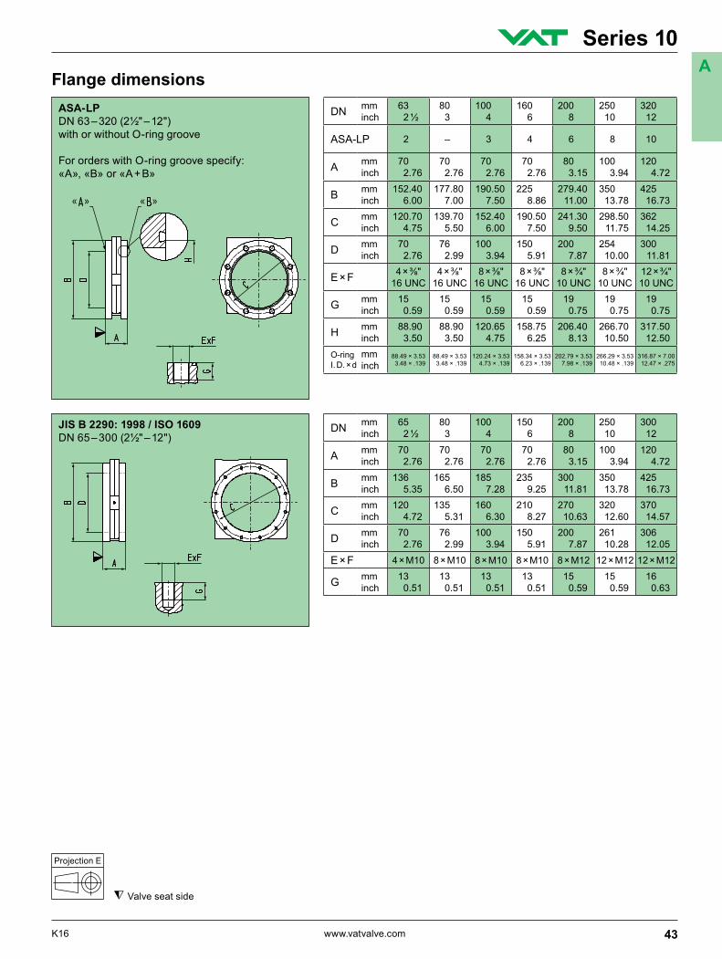
JIS B 2290: 1998 / ISO 1609 DN 65 – 300 (2½" – 12")
Projection E
DN mm inch
65 2 ½
80 3
100 4
150 6
200 8
250 10
300 12
A mm inch
70 2.76
70 2.76
70 2.76
70 2.76
80 3.15
100 3.94
120 4.72
B mm inch
136 5.35
165 6.50
185 7.28
235 9.25
300 11.81
350 13.78
425 16.73
C mm inch
120 4.72
135 5.31
160 6.30
210 8.27
270 10.63
320 12.60
370 14.57
D mm inch
70 2.76
76 2.99
100 3.94
150 5.91
200 7.87
261 10.28
306 12.05
E × F 4 × M10 8 × M10 8 × M10 8 × M10 8 × M12 12 × M12 12 × M12
G mm inch
13 0.51
13 0.51
13 0.51
13 0.51
15 0.59
15 0.59
16 0.63
Flange dimensions
Valve seat side
ASA-LP DN 63 – 320 (2½" – 12")with or without O-ring groove
For orders with O-ring groove specify:«A», «B» or «A + B»
DN mm inch
63 2 ½
80 3
100 4
160 6
200 8
250 10
320 12
ASA-LP 2 – 3 4 6 8 10
A mm inch
70 2.76
70 2.76
70 2.76
70 2.76
80 3.15
100 3.94
120 4.72
B mm inch
152.40 6.00
177.80 7.00
190.50 7.50
225 8.86
279.40 11.00
350 13.78
425 16.73
C mm inch
120.70 4.75
139.70 5.50
152.40 6.00
190.50 7.50
241.30 9.50
298.50 11.75
362 14.25
D mm inch
70 2.76
76 2.99
100 3.94
150 5.91
200 7.87
254 10.00
300 11.81
E × F 4 × ⅜" 16 UNC
4 × ⅜" 16 UNC
8 × ⅜" 16 UNC
8 × ⅜" 16 UNC
8 × ¾" 10 UNC
8 × ¾" 10 UNC
12 × ¾" 10 UNC
G mm inch
15 0.59
15 0.59
15 0.59
15 0.59
19 0.75
19 0.75
19 0.75
H mm inch
88.90 3.50
88.90 3.50
120.65 4.75
158.75 6.25
206.40 8.13
266.70 10.50
317.50 12.50
O-ring I. D. × d
mm inch
88.49 × 3.53 3.48 × .139
88.49 × 3.53 3.48 × .139
120.24 × 3.53 4.73 × .139
158.34 × 3.53 6.23 × .139
202.79 × 3.53 7.98 × .139
266.29 × 3.53 10.48 × .139
316.87 × 7.00 12.47 × .275
43K16 www.vatvalve.com
Series 10A