engineering [email protected] session 1: …thomasblairpe.com/ppe/lecture1_rev7_slides.pdf ·...
TRANSCRIPT

Welcome to
Energy
Production
Systems
Engineering Thomas Blair, P.E. USF Polytechnic – Engineering
Session 1:
Introduction &
Electrical Safety
Spring 2012

Energy Production Engineering Thomas Blair, P.E.
Session 1: Introduction & Electrical Safety Introduction to Energy Production Systems
Engineering
Electrical Installation Safety Requirements
Electrical Safe Work Practices

Energy Production Engineering Thomas Blair, P.E.
Introduction to Energy Production Systems Engineering

Energy Production Engineering Thomas Blair, P.E.
Welcome
Syllabus Contact Information
Schedule Homework
Tours Project Exams
Questions?
4

Energy Production Engineering Thomas Blair, P.E.
EPE will cover…
Safety related issues Energy conversion processes Systems needed Equipment utilized Engineering documentation & calculations Instrumentation and controls Thermodynamic processes Combustion process Efficiency & heat rate calculations
5

Energy Production Engineering Thomas Blair, P.E.
Electrical Network
“Raw Energy Resource Recovery” “Resource Delivery” “Generation (energy production/conversion)” “Transmission” “Distribution” “Utilization”
6

Energy Production Engineering Thomas Blair, P.E.
Raw Energy Resources
Coal Oil
Natural Gas Hydroelectric
Biofuels Geothermal
Solar Wind
Other?
7

Energy Production Engineering Thomas Blair, P.E.
Coal
Various Types Anthracite, Bituminous, Subbituminous, Lignite - BTU/lb varies from 14K – 6K Contains Ash, Sulfur, and other components
8

Energy Production Engineering Thomas Blair, P.E.
Coal Analysis
Grindability Index, Heating value, Ultimate analysis, Sulfur forms, Ash composition, Ash fusion temperatures
9

Energy Production Engineering Thomas Blair, P.E.
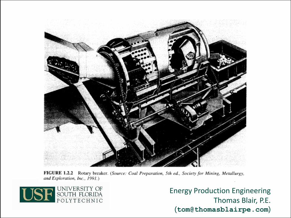
Coal Processing
Coal Storage Coal Cleaning (Separation) Coal Crushing/Pulverizing Coal Drying Coal Delivery
10


Energy Production Engineering Thomas Blair, P.E.
Coal Handling
Weighing and sampling Cross stream sampling Dust Control Collection / Suppression Freeze control Mechanical / Chemical Storage and Handling Active / Reserve Storage Combustion prevention
17


Energy Production Engineering Thomas Blair, P.E.
Oil & Natural Gas
Oil Storable / Gas used on delivery Combined cycle Rankine = steam cycle Brayton = combustion cycle Efficiency about 50% Brayton & Rankine cycle alone efficiency about 30% Multiple fuel design for varying availability / cost
25
Energy Production Engineering Thomas Blair, P.E.
Nuclear Energy
Fission, Breeder (fertile), Fusion Uranium & Plutonium primary elements Fuel assembled in ceramic pellets & inserted in fuel rods with helium in gap
26


Energy Production Engineering Thomas Blair, P.E.
Nuclear Energy
Helium Gas improve Thermal conductivity Expansion Spring, thermal expansion Zircaloy Tube cladding UO2 Fuel Pellet
28

Energy Production Engineering Thomas Blair, P.E.
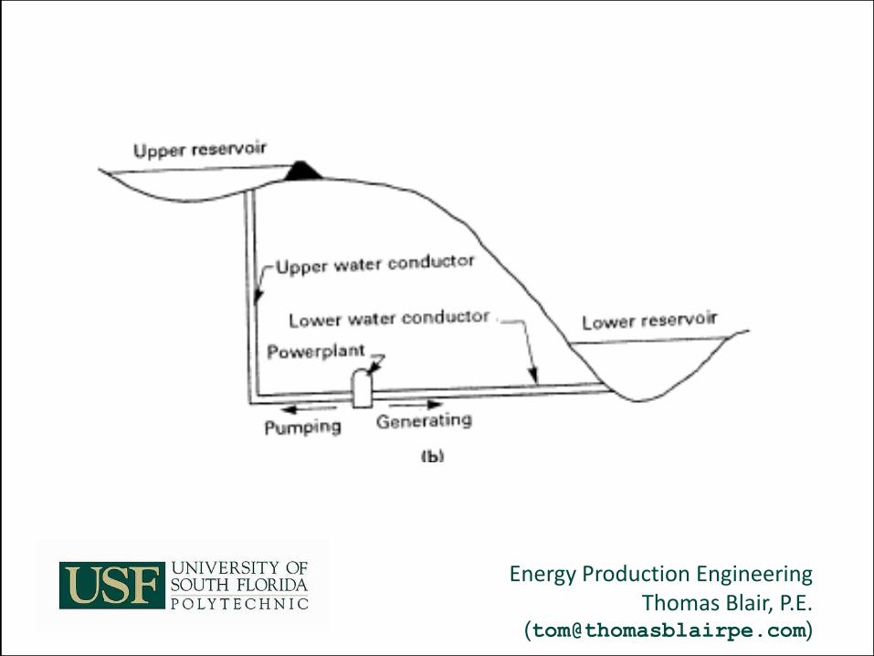
Hydro-Electric
Oldest & renewable High capitol cost Convert Potential Energy to Electric Energy Falling Water / Tides / Pumped Storage
29


Energy Production Engineering Thomas Blair, P.E.
Hydro-Electric
Falling Water Design – Headwater is stored behind Dam Flow is controlled through water turbine. Turns generator at typically slower RPM Slower rotation = more poles in generator Generator typically larger in diameter and shorter in length – typically salient pole design.
31


Energy Production Engineering Thomas Blair, P.E.
Hydro-Electric Turbine Generator
33

Energy Production Engineering Thomas Blair, P.E.
Hydro-Electric
Pumped Storage is used to provide energy during peaks. During low load, water is pumps to reservoir. During high load, water from reservoir turn turbine.
34

Energy Production Engineering Thomas Blair, P.E.
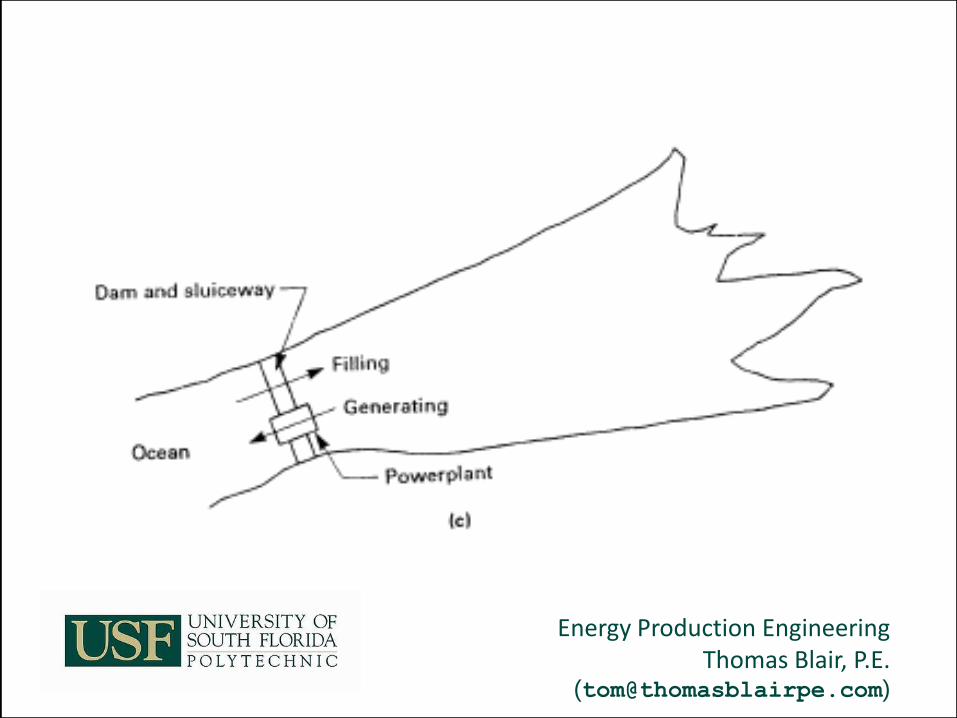
Hydro-Electric
Tidal – During tide level changes, water enters/leaves reservoir and drives turbine generator.
36

Energy Production Engineering Thomas Blair, P.E.
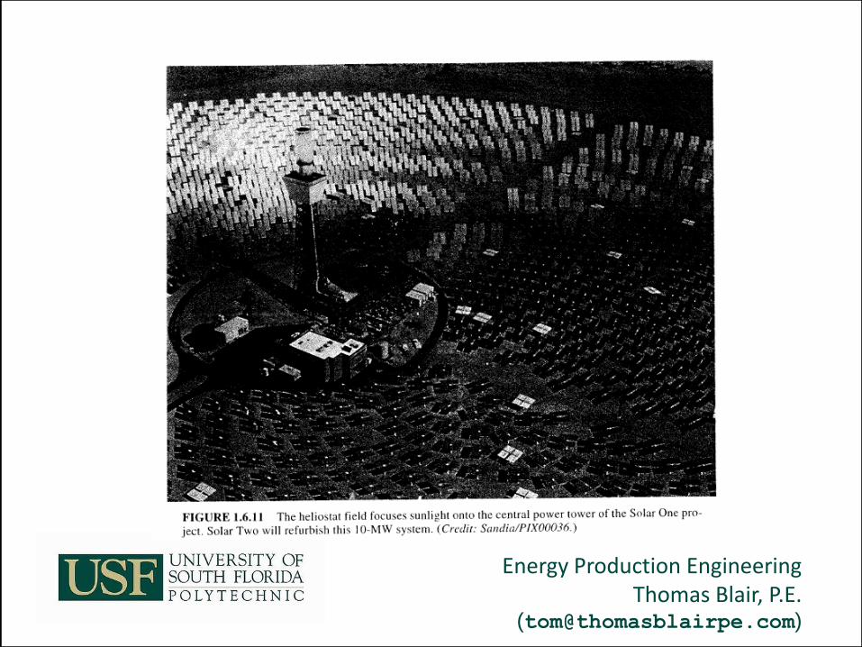
Solar Energy
Photovoltaic cell & Thermal Energy Solar Cells – Flat Plate & Concentrated Solar Power Solar Cells – direct conversion to DC
38


Energy Production Engineering Thomas Blair, P.E.
Solar Energy
The PS10 concentrates sunlight from a field of heliostats on a central tower 41

Energy Production Engineering Thomas Blair, P.E.
Solar Energy
11 MW Serpa solar power plant in Portugal 42

Energy Production Engineering Thomas Blair, P.E.
Solar Energy
43
Type Of System
Solar Concentration {suns}
Operating Temperature {C}
Efficiency {%}
Trough Electric
80 350 10 - 14
Power Tower
800 560 15 - 20
Dish Stirling
3000 800 24 - 28

Energy Production Engineering Thomas Blair, P.E.
Geothermal
65 Geothermal plants in operation Three factors needed 1. Heat conducts laterally or from below 2. There is interconnected facture shallow
enough to be drilled 3. Water/Steam fills the network
44

Energy Production Engineering Thomas Blair, P.E.
Geothermal
Steam rising from the Nesjavellir Geothermal Power Station in Iceland. 45

Energy Production Engineering Thomas Blair, P.E.
Wind Energy
Location important Surveys Development cost
46


Energy Production Engineering Thomas Blair, P.E.
Biomass Energy
Absorbs CO2 during growth to offset CO2 during combustion Minimal Sulfur Ash used as fertilizer Renewable
48


Energy Production Engineering Thomas Blair, P.E.
End of Introduction to Energy Production Engineering
Energy Production Engineering Thomas Blair, P.E.
Electrical Safety
Installation Safety Requirements


Energy Production Engineering Thomas Blair, P.E.
Aisle Working Space < 600V
54
Volts Live to Insulated
Live to Gnd Live to Live
Line - Gnd
0 – 150 900mm 900mm 900mm
3ft 3ft 3ft
151 – 600 900mm 1.1 m 1.2 m
3ft 3.5 ft 4 ft


Energy Production Engineering Thomas Blair, P.E.
Access to working space < 600V <1200 A svc – at least one
entrance 2 personnel doors 24in
x 6 ft With panic hardware
56

Energy Production Engineering Thomas Blair, P.E.
Access to working space < 600V If >1200A or >1.8m (6 ft)
2 personnel doors 24in x 6 ft With panic hardware
Exception One door if unobstructed Or if double working space depth (aisle)
57

Energy Production Engineering Thomas Blair, P.E.
Access to working space < 600V
58

Energy Production Engineering Thomas Blair, P.E.
Minimum Clear Working Space > 600V
59
Voltage ph-
gnd
Live vs
Insulated
Live vs gnd Live vs live
601-2500v 900mm 3ft 1.2m 4ft 1.5m 5ft
2501-9000v 1.2m 4ft 1.5m 5ft 1.8m 6ft
9001-25kV 1.5m 5ft 1.8m 6ft 2.8m 9ft
25001-75kV 1.8m 6ft 2.5m 8ft 3.0m 10ft
Above 75kV 2.5m 8ft 3m 10ft 3.7m 12ft

Energy Production Engineering Thomas Blair, P.E.
Fence Requirements ANSI C2, National Electrical Safety Code
60

Energy Production Engineering Thomas Blair, P.E.
Fence Requirements ANSI C2, National Electrical Safety Code
61

Energy Production Engineering Thomas Blair, P.E.
Clearance from Gnd 3m (10 ft) – sidewalks & areas accessible to
pedestrians only 3.7m (12ft) – driveways and residential property (<
300Vlg) 4.5m (15ft) - driveways and residential property (>
300Vlg) 5.5m (18ft) – streets, alleys, and areas exposed to
truck traffic
62

Energy Production Engineering Thomas Blair, P.E.
Clearance from Gnd • ANSI C2, National Electrical Safety Code
63


Energy Production Engineering Thomas Blair, P.E.
Hazardous (Classified Locations) • Equipment labeled class, gas classification
group, and operating temperature. Class I equipment temp < auto ignition temp
• Threaded conduit wrench tight
• Equipment selection under supervision of PE
• Documentation required
• Flexible conduit must have parallel bonding jumper.
65

Energy Production Engineering Thomas Blair, P.E.
Definitions • Class I location where flammable gasses or
vapors may be present in air to at explosive level
– Div1 – exist under normal operations or frequently or faulty equipment operation may cause simultaneous failure of elect. Equipment.
– Div2 – liquids / gasses used, but not normally in explosive concentrations or concentration prevented by positive mechanical ventilation or is adjacent to class I, div 1
66

Energy Production Engineering Thomas Blair, P.E.
Definitions Class II location where combustible dust may be
present Div1 – exist under normal operations or faulty
equipment operation may cause simultaneous failure of elect equipment or where combustible dusts are eclectically conductive
div2 – combustible dusts not normally in explosive concentrations or concentration may prevent cooling of electrical equipment
67
Energy Production Engineering Thomas Blair, P.E.
Definitions Class III location where easily ignitable fibers may
be present Div1 – where fibers are produced handled, or
used Div2 – areas where stored or handled other
than manufacturing process
68

Energy Production Engineering Thomas Blair, P.E.
Area Classification NFPA 497 – Classification of Flammable Liquids, Gases, or Vapors and of Hazardous (Classified) Locations for Electrical Installations in Chemical Process Area NFPA 499 – Classification of Combustible Dusts and of Hazardous (Classified) Locations for Electrical Installations in Chemical Process Area
69

Energy Production Engineering Thomas Blair, P.E.
Area Classification NFPA 497
70

Energy Production Engineering Thomas Blair, P.E.
Burner Management (Combustion Control)
Boiler Control
NFPA 85 – Boiler and Combustion Systems Hazards Code Startup / Shutdown sequence Trip Sequence
71

Energy Production Engineering Thomas Blair, P.E.
What are Electrical Hazards? Fire Ignition Electric Shock Arc Flash Arc Blast Fall Projectile Other?
72

Energy Production Engineering Thomas Blair, P.E.
Electric Shock To eliminate this hazard, we need to know The source of the hazard How the exposure could occur How the human body would react What action is necessary to reduce / eliminate hazard
73

Energy Production Engineering Thomas Blair, P.E.
Reducing Shock Hazard Can the circuit be de-energized If not, how can exposure occur What action would minimize the hazard What PPE would minimize the exposure
74

Energy Production Engineering Thomas Blair, P.E.
Recent Electrician Survey 97% had experienced a shock at work sometime in the past 26% witnessed an injury 58% were exposed to a possible injury every day.
75

Energy Production Engineering Thomas Blair, P.E.
Electrocutions by Age <20 = 10% 20-24 = 18% 25-34 = 34% (IKE) 35-44 = 22% 45 – 54 = 10% >55 = 6%
76

Energy Production Engineering Thomas Blair, P.E.
Electrical Shock Average of 30,000 electrical contact injuries annual in US Average of 3 electrocutions every day >50% of these occurred on less than 600v 4th leading cause of industrial death 7 ½ watts @ 120v is more that enough to kill
77

Energy Production Engineering Thomas Blair, P.E.
Shock Hazard Analysis Determines Voltages Limited, restricted, and prohibited boundary requirements PPE
78

Energy Production Engineering Thomas Blair, P.E.
79
Effect of Current AC Current in Amps – Men
AC Current in Amps - Women
Perception threshold (tingling) 0.0010 0.0007
Slight shock-not painful (no loss of ctrl) 0.0018 0.0012
Shock-Painful (no loss of ctrl) 0.0090 0.0060
Shock-severe (muscle ctrl loss, breathing difficulty)
0.0230 0.0150
Possible Ventricular Feb. (3 sec shock, “let go” threshold)
0.1000 0.1000
Possible Ventricular Feb. (1 sec shock) 0.2000 0.2000
Heart muscle activity ceases 0.5000 0.5000
Tissue and organs burn 1.5000 1.5000

Energy Production Engineering Thomas Blair, P.E.
Arc Flash DIFFERENT FROM SHOCK PROTECTION
80

Energy Production Engineering Thomas Blair, P.E.
Arc Flash Temperature > 35,000F This is 4 times hotter than the surface of the sun. More hospital admissions for electrical burns than shocks More than 2,000 admissions to burn centers annually Arc flashes can and DO kill at distances of 10 feet!!!
81

Energy Production Engineering Thomas Blair, P.E.
Arc Flash Exposure Energy is Expressed in cal/cm2 1 cal/cm2 Equals the Exposure on the tip of a finger by a Cigarette Lighter in One Second An Exposure Energy of Only 1.2 cal/cm2 Will Cause a 2nd Degree Burn on Human Skin
82

Energy Production Engineering Thomas Blair, P.E.
Arc Blast Cu expands by 67,000 times it solid volume during arc event Pressure hazard cause fall injuries Sound can exceed 160dB, rupturing ear drum Shrapnel leaves arc blast area at speeds exceeding 700 MPH (fast enough to completely penetrate human body Pressure wave can damage lungs, brain, and central nervous system.
83

Energy Production Engineering Thomas Blair, P.E.
Definitions Arc Rating –(ATPV)- max incident energy of a PPE system prior to break open Flame Resistant (FR)– combustion is prevented, terminated, or inhibited with or without the removal of the ignition source Flash Hazard – condition cause by the release of energy caused by an electric arc Flash Protection Boundary – distance from live parts where 2nd degree burns would result if an arc flash occurred
84

Energy Production Engineering Thomas Blair, P.E.
Definitions Limited Approach Boundary – distance from live parts where shock hazard exists Prohibited Approach boundary – distance from exposed live parts where work is considered the same as making contact Restricted Approach Boundary – a distance beyond which only qualified persons may enter because it requires shock protection equipment or techniques
85

Energy Production Engineering Thomas Blair, P.E.
86
Flash
protection
boundary
Limited
approach
boundary
Restricted
approach
boundary
Prohibited
approach
boundary
Energized
electrical
conductor

Energy Production Engineering Thomas Blair, P.E.
Definitions Exposed live part – not suitably guarded, isolated, or insulated
87

Energy Production Engineering Thomas Blair, P.E.
Definitions Working Near (live parts) – Any activity inside a limited approach boundary Working On (live parts) – coming in contact with live parts with body or equipment regardless of PPE. (inside restricted approach boundary)
88

Energy Production Engineering Thomas Blair, P.E.
Establishing an Electrically Safe Work condition
The main objective of an electrically safe work condition is to reduce the risks of electric shock, flash, and arc blast by removing the energy source
89

Energy Production Engineering Thomas Blair, P.E.
Establishing an Electrically Safe Work condition
Determine all possible sources (include stored or induced energy) Interrupt Load Open disconnect device Visually Verify Apply LO/TO Use proper voltage detector to verify absence of voltage If possible induced/stored energy sources, ground conductors
90

Energy Production Engineering Thomas Blair, P.E.
Simple LO/TO Procedures Involves one set of circuit conductors or circuit parts Is not required to be written for each application Each worker is responsible for his/her own LO/TO (note – in 2012 eliminated the line of sight lockout allowed previously.)
91

Energy Production Engineering Thomas Blair, P.E.
Complex LO/TO Procedures Is allowed under certain conditions Requires a qualified person to be in charge of the procedure Requires a written plan of execution that identifies the person in charge Shall identify the method to account for all affected persons
92

Energy Production Engineering Thomas Blair, P.E.
Electrically Safe Condition Check drawings and identify all possible sources of hazardous energy Interrupt load current and open disconnects Visually verify opening of contacts where possible Apply Lockout/tagout devices according to policy Test voltage and verify operation of tester Apply grounds where necessary
93

Energy Production Engineering Thomas Blair, P.E.
Electric Safe Work Permit Used when can not de-energize (1) A description of the circuit (2) Justification (3) A description of the safe work practices (4) Results of the shock hazard analysis (5) Determination of shock protection boundaries (6) Results of the flash hazard analysis (7) The Flash Protection Boundary (8) The necessary personal protective equipment (9) Means employed to restrict access (10) Evidence of job briefing (11) Energized work approval
94
Energy Production Engineering Thomas Blair, P.E.
Test for Voltage Determine what voltage detector will be suited for application Who will use detector Verify voltage testing equipment is working before and after voltage check Define work area Test before touching every exposed conductor in work area Retest when conditions change or location unattended
95
Energy Production Engineering Thomas Blair, P.E.
Lock And Tagout A circuit part is not considered in an electrically safe condition until it is; Disconnected Under lockout/tagout Tested to verify absence of voltage If required, the circuit is grounded Each exposed person is involved Training on procedure Plan developed with up-to-date drawings Control of all sources Unique lockout/tagout devices
96

Energy Production Engineering Thomas Blair, P.E.
LO/TO Procedures Remember, the LO/TO procedure may, in itself, be hazardous
97

Energy Production Engineering Thomas Blair, P.E.
Lock And Tagout Voltage verification Coordination and auditing yearly Responsibility of employer Establish procedure Provide training Provide hardware Audit execution Audit the procedure
98

Energy Production Engineering Thomas Blair, P.E.
Job Briefing Required before every job covering Hazards Work procedures Special precautions Energy source control PPE requirements Addition job briefing required if scope of work changes
99

Energy Production Engineering Thomas Blair, P.E.
Shock Hazard Boundaries Limited, restricted, and prohibited approach boundary
100
Phase to phase voltage
Exposed Movable
Conductor
Exposed fixed circuit part
Restricted approach boundary
Prohibited approach boundary
<50 Not specified Not specified Not specified Not specified
50-300 10’ 3’ - 6” Avoid contact Avoid contact
301-750 10’ 3’ - 6” 1’ 1”
751-15kV 10’ 5’ 2’ - 2” 7”
15.1-36kV 10’ 6’ 2’ - 7” 10”

Energy Production Engineering Thomas Blair, P.E.
101
DEFINITION OF LINEMAN INSULATED GLOVE CLASSES
CLASS NUMBER
TEST VOLTAGE
AC MAXIMUM USE VOLTAGE
00 2,500 VAC 500 VAC
0 5,000 VAC 1,000 VAC
1 10,000 VAC
7,500 VAC
2 20,000 VAC
17,000 VAC
3
30,000 VAC
26,500 VAC
4 40,000 VAC
36,000 VAC

Energy Production Engineering Thomas Blair, P.E.
Flash Protection Boundary Provide protection from Burns due to arc event Limit to 1.2 cal/cm^2 (2nd degree burn) Curable burn, but still painful and can cause injury!!!
102

Energy Production Engineering Thomas Blair, P.E.
Bolted Fault vs. Arcing Fault in Medium-Voltage Switchgear
• Bolted Faults
– Current I²t
– Mechanical forces
• Testing
– Interrupting capability
– Thermal capacity of bus
– Mechanical bracing of bus
103
Typical UL test setup
Energy Production Engineering Thomas Blair, P.E.
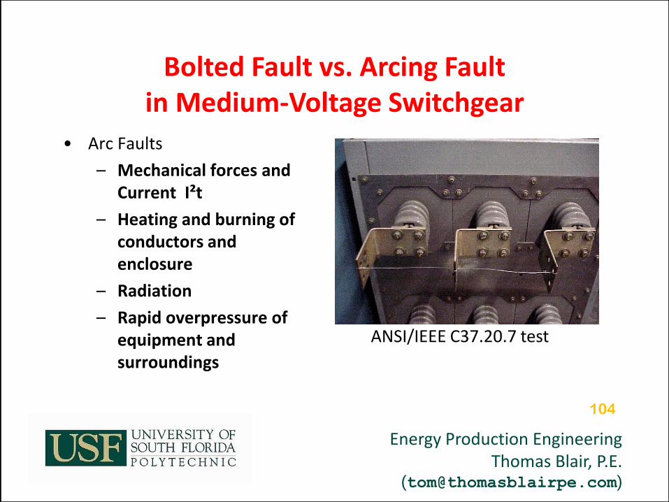
Bolted Fault vs. Arcing Fault in Medium-Voltage Switchgear
• Arc Faults
– Mechanical forces and Current I²t
– Heating and burning of conductors and enclosure
– Radiation
– Rapid overpressure of equipment and surroundings
104
ANSI/IEEE C37.20.7 test
Energy Production Engineering Thomas Blair, P.E.
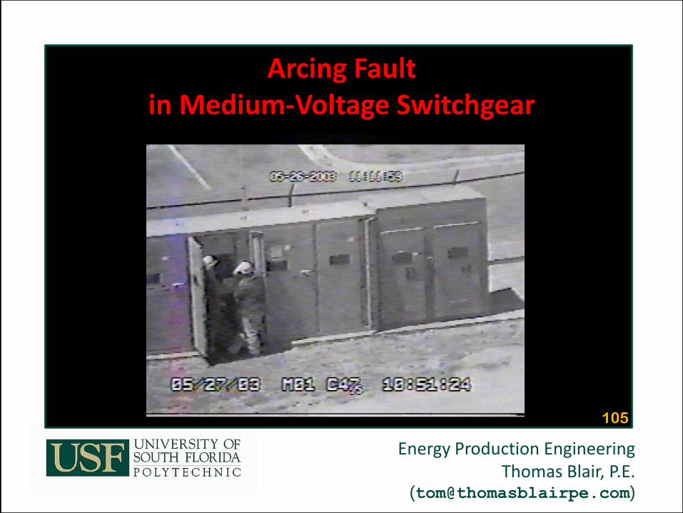
Arcing Fault in Medium-Voltage Switchgear
105

Energy Production Engineering Thomas Blair, P.E.
Electrical Safety
To be continued …

Energy
Production
Systems
Engineering
Thomas Blair, P.E. USF Polytechnic – Engineering
End of Session 1:
Introduction &
Electrical Safety
Spring 2012