english user’s manual - apc by schneider electric safety instructions! please read this manual!...
TRANSCRIPT

English User's Manual

Main Tech Support:Phone ......................... +353 91 702020Fax .............................. +353 91 755275E-Mail ......................... [email protected]
Toll-Free Numbers:Ireland ........................ 1-800-702000 x2045Austria ........................ 0660 6480Belgium ...................... 0800 15063Czech Republic .......... 0800 102063Denmark .................... 800 18 153France ......................... 0800 906 483Finland ....................... 9800 13 374Germany .................... 0130 818907Holland ...................... 0800 0224655Hungary ..................... 00800 12221Israel ........................... 177 353 2206Italy ............................. 1678 74731Luxembourg ............... 0800 2091Norway ....................... 800 11 632Poland ........................ 00800 353 1202Portugal ...................... 050 553182South Africa ............... 0800 994206Spain........................... 900 95 35 33Sweden ....................... 020 795 419Switzerland................. 0800 556177Turkey ........................ 0800 353 90275United Kingdom ........ 0800 132990
Not Toll-Free Numbers:Russia ......................... +7 095 916 7166

Important Safety Instructions!Important Safety Instructions!Important Safety Instructions!Important Safety Instructions!Important Safety Instructions!
Please read this manual!Veuillez lire ce manuel!Bitte lesen Sie dieses Anleitungshandbuch!¡Se ruega leer este manual de instrucciones!
This User's Manual provides safety, installation and operating instructions that will help you derive the fullest performance andservice life that the SymmetraTM Power Array has to offer.
PLEASE SAVE THIS USER'S MANUAL! It includes important instructions for the safe use of the SymmetraTM Power Array, andfor obtaining factory service should the proper operation of the system or the components come into question. Service or storageissues may arise at a later date, and may require reference to this User's Manual, or to the technical support information that isincluded in it.
CONSERVER CES INSTRUCTIONS! Cette notice contient des instructions importantes concernant la sécurité.
Radio Frequency Interference
NOTE: This equipment has been tested and found to comply with the limits for a Class A digital device, pursuant to Part 15 of theFCC Rules and the Class A limits for radio noise emissions from digital apparatus set out in the Radio Interference Regulations ofthe Canadian Department of Communications. These limits are designed to provide reasonable protection against harmful inter-ference when the equipment is operated in a commercial environment. This equipment generates, uses and can radiate radiofrequency energy and, if not installed and used in accordance with the instruction manual, may cause harmful interference toradio communications. Operation of this equipment in a residential area is likely to cause harmful interference in which case theuser will be required to correct the interference at his own expense.
Shielded cables must be used with this unit to ensure compliance with the Class A FCC limits.
WARNING: Changes or modifications to this unit not expressly approved by the party responsible for compliance could void theuser�s authority to operate the equipment.
Part #: 990-7779 Rev. 1
Revised 3/98

Entire contents copyright © 1998 American Power Conversion. All rights reserved; reproduction in whole or in part withoutpermission is prohibited. Symmetra, Power Array, SmartSlot, SmartCell and SNMP Adapter are trademarks of APC. Power-Chute and PowerDoctor are registered trademarks of APC. All other trademarks are the property of their respective owners.
Limited Warranty
American Power Conversion (APC) warrants its products to be free from defects in materials and workmanship for a period of oneyear from the date of purchase. Its obligation under this warranty is limited to repairing or replacing, at its own sole option, anysuch defective products. To obtain service under warranty you must obtain a Returned Material Authorization (RMA) numberfrom APC or an APC service center. Products must be returned to APC or an APC service center with transportation chargesprepaid and must be accompanied by a brief description of the problem encountered and proof of date and place of purchase.This warranty does not apply to equipment which has been damaged by accident, negligence, or mis-application or has beenaltered or modified in any way. This warranty applies only to the original purchaser who must have properly registered theproduct within 10 days of purchase.
EXCEPT AS PROVIDED HEREIN, AMERICAN POWER CONVERSION MAKES NO WARRANTIES, EXPRESS OR IMPLIED,INCLUDING WARRANTIES OF MERCHANTABILITY AND FITNESS FOR A PARTICULAR PURPOSE. Some states do notpermit limitation or exclusion of implied warranties; therefore, the aforesaid limitation(s) or exclusion(s) may not apply to thepurchaser.
EXCEPT AS PROVIDED ABOVE, IN NO EVENT WILL APC BE LIABLE FOR DIRECT, INDIRECT, SPECIAL, INCIDENTAL,OR CONSEQUENTIAL DAMAGES ARISING OUT OF THE USE OF THIS PRODUCT, EVEN IF ADVISED OF THE POSSIBIL-ITY OF SUCH DAMAGE. Specifically, APC is not liable for any costs, such as lost profits or revenue, loss of equipment, loss of useof equipment, loss of software, loss of data, costs of substitutes, claims by third parties, or otherwise. This warranty gives youspecific legal rights and you may also have other rights which vary from state to state.
Life Support Policy
As a general policy, American Power Conversion (APC) does not recommend the use of any of its products in life support appli-cations where failure or malfunction of the APC product can be reasonably expected to cause failure of the life support device orto significantly affect its safety or effectiveness. APC does not recommend the use of any of its products in direct patient care. APCwill not knowingly sell its products for use in such applications unless it receives in writing assurances satisfactory to APC that (a)the risks of injury or damage have been minimized, (b) the customer assumes all such risks, and (c) the liability of American PowerConversion is adequately protected under the circumstances.
Examples of devices considered to be life support devices are neonatal oxygen analyzers, nerve stimulators (whether used foranesthesia, pain relief, or other purposes), autotransfusion devices, blood pumps, defibrillators, arrhythmia detectors and alarms,pacemakers, hemodialysis systems, peritoneal dialysis systems, neonatal ventilator incubators, ventilators for both adults and in-fants, anesthesia ventilators, infusion pumps, and any other device designated as �critical� by the U.S.F.D.A.
Hospital grade wiring devices and leakage current may be ordered as options on many APC UPS systems. APC does not claim thatunits with this modification are certified or listed as Hospital Grade by APC or any other organization. Therefore these units donot meet the requirements for use in direct patient care.

TTTTTable of Contentsable of Contentsable of Contentsable of Contentsable of Contents
INTRODUCTIONTheory of Operation ................................................................................................................. iModes of Operation .................................................................................................................. iii
SAFETY INFORMATIONSymbols Used In This Manual ......................................................................................... safety-1Important Safety Instructions .......................................................................................... safety-1
1. PHYSICAL REPRESENTATIONThe Power Array Frame ............................................................................................................ 1-1PowerView User Interface ......................................................................................................... 1-2Grill Covers ................................................................................................................................ 1-2Power Module ............................................................................................................................ 1-2Battery Module .......................................................................................................................... 1-2Main Intelligence Module (MIM) ........................................................................................... 1-3Redundant Intelligence Module (RIM) ................................................................................... 1-3Input Circuit Breaker ................................................................................................................ 1-3Maintenance Bypass Switch ..................................................................................................... 1-3Rear View of Power Array ......................................................................................................... 1-4System Enable Switch ................................................................................................................ 1-4Communication Interface Ports .............................................................................................. 1-4SmartSlotTM Accessory Ports ..................................................................................................... 1-4REPO/Input/Output Wiring Panels ........................................................................................ 1-4Convenience Power Panel ......................................................................................................... 1-4Extended Run Battery Frame Connector ................................................................................ 1-4
2. SITE PREPARATIONSpace and Weight Considerations ........................................................................................... 2-1Transporting Power Array to Installation Site ........................................................................ 2-1Operating Conditions ............................................................................................................... 2-1BTU Output ............................................................................................................................... 2-1
3. UNPACKING AND INSTALLING FRAMEInitial Inspection ....................................................................................................................... 3-1Check For Damage .................................................................................................................... 3-1Handling Considerations ......................................................................................................... 3-1Move the Frame ......................................................................................................................... 3-1Remove Packing Materials ........................................................................................................ 3-2Remove the Frame from the Pallet .......................................................................................... 3-2Moving Battery & Power Modules .......................................................................................... 3-2
4. WIRING REQUIRMENTS & PROCEDURESWiring Overview ....................................................................................................................... 4-1Input Wiring .............................................................................................................................. 4-2Output Wiring ........................................................................................................................... 4-4Remote Emergency Power Off Wiring .................................................................................... 4-5Electrical Wiring Test/Checklist ............................................................................................... 4-6

5. SETTING UP THE POWER ARRAYOverview of Setup ..................................................................................................................... 5-1Frame Leveling Procedure ........................................................................................................ 5-1Installing the Battery Modules ................................................................................................. 5-2Installing the Power Modules ................................................................................................... 5-3Installing the Main Intelligence Module (MIM) .................................................................... 5-4Installing the Redundant Intelligence Module (RIM) ........................................................... 5-4Installing the PowerView Interface .......................................................................................... 5-5SmartSlotTM Interface Accessories ............................................................................................. 5-6Installation Test/Checklist ........................................................................................................ 5-7
6. THE POWERVIEW USER INTERFACEOverview .................................................................................................................................... 6-1PowerView Functions ............................................................................................................... 6-1PowerView LED Indicators ...................................................................................................... 6-2Navigation Keys ......................................................................................................................... 6-2Startup Screen ........................................................................................................................... 6-3Top-Level Menu Screen ............................................................................................................ 6-3Language Configuration ........................................................................................................... 6-4
7. CONFIGURING & OPERATING THE SYMMETRAIntroduction .............................................................................................................................. 7-1Step #1: Powering the System ................................................................................................... 7-1Step #2: Powering the Loads ..................................................................................................... 7-2Step #3: Review Status Conditions .......................................................................................... 7-2Step #4: Perform a Self Test ...................................................................................................... 7-4Step #5: Configure Shutdown Parameters .............................................................................. 7-5Step #6: Configure Alarms ........................................................................................................ 7-5Step #7: Review Diagnostics Menu .......................................................................................... 7-6Step #8: Review Logging Menu ................................................................................................ 7-6
8. MODULE REPLACEMENTModule Failure Alarm Indicators .......................................................................................... 8-1Technical Support and Obtaining a Replacement Module ................................................. 8-1Battery Module Replacement Procedure .............................................................................. 8-2Power Module Replacement Procedure ................................................................................ 8-3Main Intelligence Module Replacement Procedure ............................................................. 8-4Redundant Intelligence Module Replacement Procedure ................................................... 8-4
9. POWERVIEW INTERFACE MESSAGESStart-Up Messages ................................................................................................................... 9-1General Status Messages ......................................................................................................... 9-2Module Failure Messages ........................................................................................................ 9-3Threshold Alarm Messages ..................................................................................................... 9-3Bypass Messages ...................................................................................................................... 9-3General Fault Messages ........................................................................................................... 9-4
INDEX

The APC SymmetraTM Power Array is ascalable, redundant power protection sys-
tem for multiple servers and businesscritical applications. This is an introduction
to the SymmetraTM Power Array.
Introduction
MiniFrame
MasterFrame

Thank YThank YThank YThank YThank You!ou!ou!ou!ou!Thank you for investing in the SymmetraTM Power Array. Pleaseread this User's Manual thoroughly before installing the sys-tem. It provides important information for using theSymmetraTM safely and effectively.
SymmetraSymmetraSymmetraSymmetraSymmetraTMTMTMTMTM Overview Overview Overview Overview OverviewThe SymmetraTM is a high-performance, uninterruptiblepower �array� system, designed for large-scale loads. It pro-vides conditioned, reliable AC power to load equipment, andprovides protection from power blackouts, brownouts, swells,sags, surges and interference. The SymmetraTM Power Arraysystem is comprised of either a MiniFrame, or a MasterFrame,and a variable set of modules. A MiniFrame system can beconfigured to deliver a maximum output of 8kVA, and aMasterFrame system can deliver a maximum of 16kVA.
Fig I-1 MiniFrame and MasterFrame
Theory of OperationTheory of OperationTheory of OperationTheory of OperationTheory of OperationThe SymmetraTM Power Array is comprised of three func-tional components: A power processing system, a batterysource, and a control/user interface system. The relationshipof these functional components is illustrated in figure I-2.
Fig I-2 Functional Diagram of a SymmetraTM
i
System Controland Interface
CommunicationCard and
SmartSlotsTM
Powerview UserInterface
Communication Communication
Power Processing Battery Source
Charge
BypassSwitch
ACOUT
ACIN

ii
Power PrPower PrPower PrPower PrPower Processing Systemocessing Systemocessing Systemocessing Systemocessing SystemThe power processing system delivers conditioned AC outputpower with a low distortion sinewave. Under normal operat-ing conditions, power is received from the AC mains (utility)power source, conditioned by the power processing system,and delivered to the load equipment. In the event of an ACmains power source failure, the power processing system re-ceives power from the battery source (battery modules), con-verts it to conditioned AC, and delivers it to the load equip-ment. When AC mains power is present, the power processingsystem also maintains the battery source at full charge.
The power processing system in SymmetraTM is comprised ofone or more power modules. Each power module containsthe electronic components for a complete 4kVA UPS, includingthe rectifier, charger and inverter. When two or more powermodules are present, they operate in parallel, sharing the loadequally.
By configuring the system with at least one more power mod-ule than is required to power the load (a redundant powermodule), SymmetraTM can sustain a power module failureand still deliver full power to the load equipment. The failedmodule is identified by the control/user interface system, analarm is initiated to notify the user of the module failure, andthe hot-swappable module can be replaced by the user, with-out the need to power down the load equipment.
A SymmetraTM MiniFrame provides bays for up to three powermodules, and a MasterFrame provides bays for up to five.This provides the full system capacity (8kVA and 16kVA re-spectively), plus one redundant power module.
BatterBatterBatterBatterBattery Soury Soury Soury Soury SourcececececeThe battery source is comprised of parallel, hot-swappable,120V battery modules. These are housed in the SymmetraTM
frame, and in an optional XR Extension Battery frame.
A SymmetraTM MiniFrame provides bays for up to two bat-tery modules, and a MasterFrame provides bays for up tofour. Both of these frames can be connected to an XR Exten-sion Battery frame. Additional battery modules increase on-battery run time.
ContrContrContrContrControl/User Interol/User Interol/User Interol/User Interol/User InterfacefacefacefacefaceThe control/user interface system coordinates the operationof the SymmetraTM and reports status conditions via severaluser interface options. Functions performed by the control/user interface component include module coordination andstate control, analysis and reporting of system status, andreporting of alarm conditions.
Module Coordination & State Control - The SymmetraTM
incorporates a main intelligence module (MIM) that continu-ously monitors the system, and delivers data to both thePowerView user interface, and to the communication ports.The MIM coordinates the initial power up of the system, trans-fers it into and out of bypass mode, transfers the power sourcebetween the mains AC power, and the battery source, andcoordinates shutdown operations.
System Status Monitoring - The MIM gathers data about thesystem components and delivers it to both the PowerViewinterface, and to the computer interface ports. System statusmonitoring and reporting data include the current predictedrun time, the status of individual battery and power modules,the input & output voltage, input & output voltage frequency,and the size and status of the output load.
Alarm Condition Detection - The control/user interface sys-tem monitors the SymmetraTM for alarm conditions. If analarm condition is detected, the PowerView user interface ini-tiates an audible and visual alarm. Alarm conditions includeon-battery, low battery, module faults, overloads, loss of re-dundancy and a variety of other default and user defined events.All possible alarm messages and the appropriate user responsesare provided in Chapter 9.

iii
Modes of OperationModes of OperationModes of OperationModes of OperationModes of OperationThe Power Array functions in one of four modes of operationdepending on user commands, the status of the AC mains(utility) voltage, and the condition of the SymmetraTM itself.The four modes are Load-Disconnect, On-Line, On-Battery,and Bypass. The PowerView reports the operating mode.
Load-Disconnect ModeIn the load-disconnect mode, incoming mains (utility) poweris present and the system is internally powered, but no outputpower is delivered to the load equipment. The SymmetraTM
enters the load-disconnect mode at the initial power up whenthe system enable switch is switched to the �on� position. Whenthe system is operating on-line, and the �load off� commandis entered in the PowerView interface, it returns to the load-disconnect mode. Figure I-3 illustrates power flow when thesystem is operating in the load-disconnect mode.
Fig I-3 Load-Disconnect Operating Mode
On-Line Operating ModeThe on-line operating mode is the �normal� operating mode.When the system is in the on-line operating mode, the PowerArray receives AC mains (utility) power and delivers condi-tioned power to the load equipment. The Power Array main-tains proper battery charge, regulates the output voltage andfrequency, and protects the load from surges and electricalnoise. SymmetraTM will operate in this mode if it has beencommanded to turn the load on, the incoming utility voltageis present and functioning properly, and there are no prevent-ing abnormal conditions such as an overload. See figure I-4for a diagram of the power flow when the system is in the on-line operating mode.
Fig I-4 On-Line Operating Mode
System Controland Interface
CommunicationCard and
SmartSlotsTM
Powerview UserInterface
Communication Communication
Power Processing Battery Source
Charge
BypassSwitch AC
OUTACIN
System Controland Interface
CommunicationCard and
SmartSlotsTM
Powerview UserInterface
Communication Communication
Power Processing Battery Source
Charge
BypassSwitch AC
OUTACIN

On-Battery Operating ModeWhen in the on-battery mode, the Power Array draws DCpower from the battery source, converts it to conditioned ACpower and delivers it to the load equipment. SymmetraTM
typically enters this mode in the event of a mains (utility) powerfailure. It will also operate in the on-battery mode during auser initiated battery self test.
On-battery operation is limited in duration and is dependenton the number of battery modules, their state of charge, andthe size of the load. SymmetraTM will remain in the on-batterystate until either the incoming utility power is restored or thebatteries are depleted. See figure I-5 for a diagram of powerflow when the system is in the on-battery mode.
Fig I-5 On-Battery Operating Mode
Bypass Operating ModeWhen the SymmetraTM is in the bypass operating mode, thesystem is bypassed and utility power is delivered directly to theload. SymmetraTM is equipped with an automatic bypass func-tion to allow the system to automatically go into bypass mode,and a manual maintenance bypass switch to allow a user tomanually bypass the system. Either can be used to place thePower Array into bypass operating mode.
The SymmetraTM will automatically transfer to the bypassoperating mode when AC mains power is present, but theload cannot be powered by the inverter. Events which maycause this include overloads and failed non-redundant powermodules. The SymmetraTM will automatically return to theon-line mode when the triggering event clears. Figure I-6 illus-trates power flow when the system is in the bypass mode.
Fig I-6 Bypass Operating Mode
iv
System Controland Interface
CommunicationCard and
SmartSlotsTM
Powerview UserInterface
Communication Communication
Power Processing Battery Source
Discharge
BypassSwitch AC
OUTACIN
System Controland Interface
CommunicationCard and
SmartSlotsTM
Powerview UserInterface
Communication Communication
Power Processing Battery Source
Charge
BypassSwitch AC
OUTACIN

DefinitionsDefinitionsDefinitionsDefinitionsDefinitionsThe following terms are used in this manual. Review thesedefinitions for a better understanding of the SymmetraTM:
Redundancy - Indicates the presence of one or more extrapower modules which allow the system to sustain a fault andstill provide protection to the load. To be fully redundant, thesystem should be configured with a redundant intelligencemodule, and at least one redundant power module.
Note: The number of battery modules determines the length ofthe run time. While it is prudent to use the maximum numberof battery modules possible, they are not considered redundant.
N+1 Redundancy - Refers to the level of power module re-dundancy. �N� represents the number of power modules re-quired to power the load, and �+1, +2, etc.� represents thenumber of extra power modules that are present.
For example, a 7.3 kVA load requires two power modules foradequate protection. If the SymmetraTM is configured withonly two modules, it has an �N+0,� level of redundancy. (Noredundancy). If the system is configured with three powermodules, it has an �N+1� redundancy. Depending on the sizeof the load, SymmetraTM can be configured with 2, 3 or even 4extra power modules. Respectively, it would have an N+2,N+3, or N+4 level of redundancy.
Capacity - The maximum amount of output power that aSymmetraTM system can deliver. The capacity is limited by thelesser of the frame size, or the capacity of the installed powermodules.
For example, a MiniFrame (8kVA) with one power moduleinstalled (4kVA) has a system capacity of 4kVA. A MasterFrame(16kVA) with five power modules (20kVA) has a system ca-pacity of 16kVA.
Hot-swappable - The modules are �hot-swappable� meansthey can be replaced safely by a user or service provider whilethe load is still powered and fully protected.
Important InformationImportant InformationImportant InformationImportant InformationImportant InformationPlease read this User's Manual thoroughly before proceedingwith the installation of the SymmetraTM Power Array system.It provides important information about installing and usingthe SymmetraTM safely and effectively. Pay close attention totext that is accompanied by a danger, or caution symbol. Fortechnical support, see the inside front cover of this manual.
v

vi

Important Safety Information
Read this safety information com-pletely before installing or using the
SymmetraTM Power Array.
Safety Information
MiniFrame
MasterFrame

Symbols Used In This ManualSymbols Used In This ManualSymbols Used In This ManualSymbols Used In This ManualSymbols Used In This ManualThe following symbols appear in this User's Manual:
CAUTION/DANGER - Caution indicates risk ofbodily harm. Danger indicates that a risk of elec-trical shock is present and the associated proce-dures should be followed carefully.
�STAND BY MODE� - The system enable switch,and the input circuit breaker use the �stand by�mode. When either of these are switched to �standby,� the Power Array is disconnected from mains(utility) input voltage. In this mode, the systemappears to be off, although the mains (utility)power is still connected to the system. For thisreason, the standby mode is unsafe for servicingthe system. Always follow the five step Total PowerOff procedure before servicing the Power Array.(See procedure at right.)
�OFF POSITION� - The maintenance bypassswitch is the only switch that can be placed in the�off� position. When switched to the �off � posi-tion, the Power Array functions normally, receiv-ing mains (utility) power, and delivering condi-tioned power to the load equipment.
�ON POSITION� - All three switches (The sys-tem enable switch, the maintenance bypass switchand the input circuit breaker) can be placed in the�on� position. See the description for each of theseswitches in Chapter 1.
SAFETY EARTH GROUND - Indicates the pri-mary safety ground.
Safety
Safety-1
IMPORIMPORIMPORIMPORIMPORTTTTTANT SAFETY INSTRUCTIONSANT SAFETY INSTRUCTIONSANT SAFETY INSTRUCTIONSANT SAFETY INSTRUCTIONSANT SAFETY INSTRUCTIONS
n SAVE THIS USER MANUAL - This manual contains im-portant instructions that should be followed during in-stallation and maintenance of the Power Array, and forinstallation or replacement of the battery and power mod-ules.
CONSERVER CES INSTRUCTIONS. CETTE NOTICECONTIENT DES INSTUCTIONS IMPORTANTES
CONCERNANT LA SÉCURITÉ.
n Connection to the branch circuit (mains utility powersource) must be performed by a licensed electician.
n Installation of the power and battery modules can be per-formed by any individual with no previous technical ex-perience.
n Operation of the SymmetraTM can be performed by anyindividual with no previous technical experience.
n The protective earth conductor for the SymmetraTM car-ries the leakage current from the load devices (computerequipment). Therefore, the size of the conductor must beat least as large as the wire required by IEC 950. IEC 950states the following nominal cross-sectional areas:- 2.5 mm2 for rated current between 17 & 25 A- 6 mm2 for rated current between 33 & 40 A- 10 mm2 for rated current between 41 & 63 A- 16 mm2 for rated current between 64 & 80 A
n FIVE STEP TOTAL POWER OFF PROCEDURETo remove all power from the Power Array (Total PowerOff), the following events must occur in the order listed:1. Set system enable switch to the �stand by� position.2. Set input circuit breaker to the �stand by� position.3. Remove all battery modules from the Power Array.4. Disconnect XR external battery cabinet (if present).5. Disconnect the mains/branch circuit breaker.

Safety
Safety-2
n CAUTION: Risk of Electrical Shock and Energy Hazard,120V, 7.2 Ah battery module. Before replacing batterymodules, remove conductive jewelry such as chains, wristwatches and rings. High short circuit current throughconductive materials could cause severe burns.
n CAUTION: Do not dispose of batteries or battery mod-ules in a fire. The batteries may explode.
n CAUTION: Do not open or mutilate battery modules orbatteries. Released electrolyte is harmful to the skin andeyes. It may be toxic.
n While battery modules are user replaceable, servicing ofthe battery modules themselves should be performed orsupervised by personnel knowledgeable of batteries andthe required precautions. Keep unauthorized personnelaway from batteries.
n When replacing or adding battery modules to the PowerArray system, use only the �SYBATT SymmetraTM Bat-tery Module.� See the APC telephone numbers listed onthe inside cover of this manual for technical support, orto obtain replacement modules.

This chapter provides an illustrated descrip-tion of the SymmetraTM Power Array system
and each of the modular components.Before proceeding, examine the illustration
below. It depicts a MiniFrame (8kVA) and aMasterFrame (16kVA) Power Array as theyappear during normal operating conditions.
Chapter One
Physical Representation
MiniFrame
MasterFrame

The Power Array FrameThe Power Array FrameThe Power Array FrameThe Power Array FrameThe Power Array FrameThe SymmetraTM Power Array frame serves as the base forthe modular components of the system. The MiniFrame pro-vides bays for three power modules and two battery mod-ules. The MasterFrame provides bays for five power mod-ules and four battery modules. The bay at the top right housesthe main intelligence module (MIM) and redundant intelli-gence module (RIM).
Wiring input/output access panels and terminal blocks, a sys-tem enable switch, an input circuit breaker and a mainte-nance bypass switch are located near the bottom of the frame.A MiniFrame with all battery and power module bays loadedis depicted in figure 1-1. A MasterFrame with factory in-stalled MIM and RIM, and empty power and battery modulebays is depicted in figure 1-2.
Fig 1-1 A Fully Loaded MiniFrame (grill covers removed)
Chapter 1 - Physical Representation
1-1
FivePower
ModuleBays
FourBatteryModuleBays
Fig 1-2 An Empty MasterFrame (grill covers removed)
RedundantIntelligenceModule
MainIntelligenceModule
MiniFrame
BatteryModules
PowerViewInterface
PowerModules
InputCircuit
Breaker
MaintenanceBypassSwitch
MainIntelligenceandRedundantIntelligenceModules

Power ModulePower ModulePower ModulePower ModulePower ModuleThe power module is a self-contained, 4kVA UPS (withoutbatteries) housed inside a metal enclosure. A blind matingconnector at the rear of the module engages with a connec-tor inside the frame. Power modules are installed in the ver-tical column of bays at the left of the frame. These bays arelabeled L1, L2, L3, etc.
1-Blind Mating Connector, 2-Positioning Handle,3-Cooling Fan Grill, 4-Alignment Runners,
5-Seating Tabs, 6-Flip Latch Micro Switch
Fig 1-5 Power Module
In the event of a power module failure, the PowerView ini-tiates an audible alarm and displays an error message. Thepower module is hot-swappable. Instructions for modulereplacement are provided in Chapter 8.
BatterBatterBatterBatterBattery Moduley Moduley Moduley Moduley ModuleThe battery module is comprised of a series of ten 12V bat-teries housed inside a plastic enclosure. A blind mating con-nector at the rear of the module engages with a connectorinside the frame.
Battery modules are installed in the vertical column of baysat the right of the frame. These are labeled R2, R3, R4, etc.(R1 houses the intelligence modules.) The condition andcharge of each battery module is reported on the PowerView.If a battery module fails, an alarm is initiated. Battery mod-ules are hot-swappable and user replaceable.
PowerPowerPowerPowerPowerview User Interview User Interview User Interview User Interview User InterfacefacefacefacefaceThe PowerView incorporates a 4 x 20 alphanumeric LCDscreen with four navigation keys, four LED status indicators,and an audible alarm. The display communicates with thePower Array via a short RJ45 connector cable that is hardwiredinto the intelligence modules bay. The PowerView can bemounted on the front of the frame, stand on top of the frame,or it can be installed at a remote location. A 6.1m (20') RJ45cable is provided for remote installation.
The alphanumeric LCD screen displays system status, faultreporting, and module diagnostics information. The navi-gation keys scroll through an elaborate menu. Chapter 6 pro-vides detailed information about the PowerView.
Alarm thresholds and parameters are set with the PowerView.In the event of an alarm condition, the PowerView emits bothaudible and visual alarm indicators.
1-LED Status Indicators, 2-LCD Screen, 3-Navigation Keys
Fig 1-3 PowerView User Interface
Grill CoversGrill CoversGrill CoversGrill CoversGrill CoversEach level of the frame is equipped with a grill cover. Thesecovers are interchangeable, and snap securely onto the frame.When removing, temporarily storing, and replacing grill cov-ers, use care to prevent them from being marred or scratched.
Fig 1-4 Front Grill Cover Removal and Replacement
1-2
Chapter 1 - Physical Representation

1-Blind Mating Connector, 2-Retaining Flange,3-Positioning Handle, 4-Runners
Fig 1-6 Battery Module
Main Intelligence Module (MIM)Main Intelligence Module (MIM)Main Intelligence Module (MIM)Main Intelligence Module (MIM)Main Intelligence Module (MIM)The MIM is the computer for the Power Array system. Itgathers and processes data, including monitoring the condi-tion of each of the modules.
The PowerView functions as the user interface for the MIM,and is used to access data, and to configure the system. Whena redundant intelligence module is installed and function-ing, the main intelligence module can be replaced withoutplacing the load at risk. The main intelligence module alsocommunicates with an external battery frame (if present).The main intelligence and the redundant intelligence mod-ule are factory installed in the upper right bay of the frame.
Important: The MIM is always installed in the bottom rack,and the RIM is always installed in the top rack in this bay.
1-Blind Mating Connector, 2-Flip Latch Micro Switch,3-Retaining Screw, 4-Positioning Handle, 5-Installation Rail
Fig 1-7 Main & Redundant Intelligence Module
Chapter 1 - Physical Representation
1-3
Redundant Intelligence Module (RIM)Redundant Intelligence Module (RIM)Redundant Intelligence Module (RIM)Redundant Intelligence Module (RIM)Redundant Intelligence Module (RIM)The redundant intelligence module is a backup version ofthe main intelligence module. It provides redundancy in theevent of a MIM failure or while a MIM is being replaced. If afunctioning MIM is present, the RIM can be removed andreplaced without placing the load at risk. The condition ofthe RIM can be determined with the PowerView display.
Input CirInput CirInput CirInput CirInput Circuit Brcuit Brcuit Brcuit Brcuit BreakereakereakereakereakerThe input circuit breaker protects the Power Array from ex-treme overloads. When switched to �stand by,� the PowerArray is disconnected from incoming (mains) voltage. Whenswitched to the �on� position, power flows from the mainspower source into the Power Array. Under normal operatingconditions, the input circuit breaker always remains in the�on� position.
Fig 1-9 Input Circuit Breaker & Maintenance Bypass Switch
Maintenance Bypass SwitchMaintenance Bypass SwitchMaintenance Bypass SwitchMaintenance Bypass SwitchMaintenance Bypass SwitchWhen switched to the �on� position, the maintenance bypassswitch bypasses the Power Array and causes the load equip-ment to be powered directly from the mains power source.When it is switched to the �off� position, mains power flowsinto the Power Array, and conditioned power is delivered tothe load equipment. The load equipment is unprotected whenthe maintenance bypass switch is in the �on� position. Undernormal operating conditions, the maintenance bypass switchremains in the �off� position.
(Front of Frame)

Rear VRear VRear VRear VRear View of a Power Ariew of a Power Ariew of a Power Ariew of a Power Ariew of a Power ArrayrayrayrayrayThe rear of a MiniFrame Power Array system is shown be-low. (The rear of a MasterFrame is identical.) Each of thecomponents is described in a section that follows:
System Enable SwitchThe system enable switch regulates power to the intelligencemodules. It does not power the load. When switched to the�on� position, the Power Array enters the load-disconnectoperating mode. When switched to �stand by,� the intelli-gence modules are disconnected from the mains voltage, andthe system shuts down.
Note: The load is not powered until the �power the load� com-mand is entered into the PowerView user interface.
Communication Interface PortsThere are three interface ports: A Remote PowerView portfor the 6.1 m (20') RJ45 PowerView cable, a 9-pin computerinterface port for APC PowerChute Plus software, and a bat-tery communication port for an XR Extended Run Frame.
Smart SlotsTM Accessory PortsAPC manufactures a set of auxiliary user interface accesso-ries, called SmartSlotTM devices. Four SmartSlotTM installa-
tion ports are provided. SmartSlotTM interface options includethe following:n Protection and safe shutdown of multiple serversn SNMP adaptor for accessing data via a networkn CallUPSTM - telephone notification of power eventn MeasureUPSTM - monitor environmental conditionsn Control and monitor Power Array via modemNote: Use only SmartSlotTM devices labeled �SymmetraTM
Compatible.�
REPO/Input/Output Wiring Access PanelsWiring terminal blocks for input and output wiring and forremote emergency power off (REPO) switch installations areaccessed through these panels.
Note: Wiring is to be installed by a qualified electrician only.
Convenience Power PanelEight IEC 320 C13 type power outlets are provided. The out-lets are arranged in two sets of four. Each set is equipped witha circuit breaker.
Extended Run Battery Frame ConnectorAn optional XR Extended Run Battery Frame can be connectedto the Power Array via this connector. See the User�s Manualincluded with the XR Extended Run Battery Frame.
Fig 1-10 Rear View of a Mini Frame SymmetraTM Power Array System
SmartSlotTM
AccessoryPorts
MiniFrame
InputWiringAccessPanels
CommunicationInterface
Ports
OutputWiringAccessPanels
XR Extended RunBattery Frame
Connector
SystemEnableSwitch
1-4
Chapter 1 - Physical Representation
REPO WiringAccess Panels
Convenience PowerPanel

This chapter provides the environmental andstructural requirements for a SymmetraTM Power
Array system. Included are the weights, dimen-sions, and heat output of a functioning system.
Chapter Two
Site Preparation
MiniFrame
MasterFrame

Space and WSpace and WSpace and WSpace and WSpace and Weight Considerationseight Considerationseight Considerationseight Considerationseight ConsiderationsThe Power Array frame is 61cm (24") wide and 68.6cm (27")deep. Refer to table 4-1 for the height and weight of fullyloaded systems.
eziSemarF eziSemarF eziSemarF eziSemarF eziSemarF thgieH thgieH thgieH thgieH thgieH thgieW thgieW thgieW thgieW thgieWdedaoLylluF dedaoLylluF dedaoLylluF dedaoLylluF dedaoLylluF
emarFiniMmc7.87
"13gk832bl525
emarFretsaMmc1.231
"25gk914bl529
Table 2-1 Height & Weight (Loaded w/ Modules)
Make sure there is adequate space and structural integrity tosupport the fully loaded frame. Refer to figure 2-1. The weightof the Power Array rests on four 3.8cm (1.5") diameter levelingfeet. Positions of the leveling feet are shown. When installingthe frame, allow 30.5cm (12") of clearance behind the framefor adequate airflow. (Air flows in through the front of theframe and out the back.) Allow 122cm (48") of clearance inthe front of the SymmetraTM to access the PowerView and toinstall modules.
Fig 2-1 System Footprint and Required Clearance
Transporting Power Array to Installation SiteWhen it is shipped, the Power Array frame is bolted to a cus-tom-designed pallet. The modules are stacked on either oneor two additional pallets. It is recommended that these palletsbe moved from the receiving dock to the installation area witha pallet jack. Make sure there is enough space and structuralintegrity to move these pallets.
Operating ConditionsThe Power Array is intended for installation in a temperaturecontrolled indoor area that is free of conductive contaminants.The operating evironment must be clean, dry, and protected.The atmosphere must be free of dust and corrosive fumes.Adequate airflow must be provided for the operation of thesystem. Make sure environmental conditions are within thefollowing parameters:
n Relative Humidity: 0 to 95%, non-condensing.n Temperature: 0°C to 40°C (32°F to 104°F).n Elevation: 0m to 3,048m (0ft to 10,000ft).n Electro-Static Discharge (ESD) Susceptibility: The Power
Array and all modules are capable of withstanding�through air� electro-static discharges up to an ampli-tude of +/-15kV and �direct discharge� electro-static dis-charges up to an amplitude of +/-8kV without failure,abnormal operation, or degradation in performance. ESDtest methods conform to IEC 801-2.
BTU OutputRefer to table 2-2 for BTU output of a fully loaded PowerArray system. The BTU output is significantly higher whilethe batteries are charging. Under normal operating condi-tions, battery recharge periods are relatively infrequent.
emarF emarF emarF emarF emarFeziS eziS eziS eziS eziS
rH/UTB rH/UTB rH/UTB rH/UTB rH/UTB((((( seirettab seirettab seirettab seirettab seirettab
ylluf ylluf ylluf ylluf ylluf)degrahc )degrahc )degrahc )degrahc )degrahc
rH/UTB rH/UTB rH/UTB rH/UTB rH/UTB((((( ,gnigrahcseirettab ,gnigrahcseirettab ,gnigrahcseirettab ,gnigrahcseirettab ,gnigrahcseirettab
yticapacemarflluf yticapacemarflluf yticapacemarflluf yticapacemarflluf yticapacemarfllufeludom1+Nhtiw eludom1+Nhtiw eludom1+Nhtiw eludom1+Nhtiw eludom1+Nhtiw
)noitarugifnoc )noitarugifnoc )noitarugifnoc )noitarugifnoc )noitarugifnoc
emarFiniM 314,3 076,8
emarFretsaM 628,6 046,51
Table 2-2 BTU Output
Temporary Storage of ModulesThe battery and power modules must be temporarily storeduntil the frame is permanently installed. To preserve batterylife, always store batteries in a cool, dry place.
Chapter 2 - Site Preparation
2-1
Front Clearance
RearClearance

2-2
Chapter 2 - Site Preparation

This chapter provides the procedures for inspect-ing the SymmetraTM frame and modules when
they arrive. It includes procedures for moving theframe and modules to the installation site and
for removing them from the pallet.
Chapter Three
Unpacking and Installing Frame
MiniFrame
MasterFrame

Move the FrameMove the FrameMove the FrameMove the FrameMove the Frame1. Plan the Route - Make sure all passages are large enough toaccommodate the frame and the pallet jack. Check to see thatthe floor has sufficient strength. See Table 3-1 for weights anddimensions. Check doorways, elevators, ramps, etc, to insurethere are no non-negotiable corners, step-ups, or offsets. Se-lect a route that provides the smoothest possible floor surface.
2. Staging Area - A smooth, level floor surface is required toposition the frame pallet, to remove the packaging materials,and to install the ramp. It must provide adequate space fortwo people to carefully roll the frame down the ramp and ontothe floor. See Figure 3-1 below for staging area dimensions.
3. Using the Pallet Jack - Carefully move the frame to thestaging area.
Fig 3-1 Staging Area
Initial InspectionInitial InspectionInitial InspectionInitial InspectionInitial InspectionThe SymmetraTM Power Array system is shipped on pallets.The system frame is bolted to one pallet, and the modules areboxed and stacked on one or two additional pallets.
Check For Damage1. Inspect the Packaging - for damage or signs of mishan-dling before moving the pallets. If damage is detected, note iton the Bill of Lading.
2. If Any Damage Is Detected - file a damage claim with theshipping agency within 24 hours. Inform APC of the damageclaim and the condition of the equipment.
3. System Administrator- make sure the system administra-tor participates in the initial inspection.
artemmyS artemmyS artemmyS artemmyS artemmyS MTMTMTMTMT
tnenopmoC tnenopmoC tnenopmoC tnenopmoC tnenopmoC
snoisnemiD snoisnemiD snoisnemiD snoisnemiD snoisnemiDmcHxDxW
)sehcni(
thgieW thgieW thgieW thgieW thgieW)bl(gk
emarFiniM6 x1 6.86 x 7.87
)"13x"72x"42(gk631
( bl003 )
emarFretsaM16 6x 6.8 x 1.231
( )"25x"72x"42gk632
( bl025 )
yrettaBeludoM
9.22 5x .0 2.51x8( )"6x"02x"9
gk82( bl06 )
eludoMrewoP4.52 x 8.05 x 2.51
( "6x"02x"01 )
gk61( bl53 )
Table 3-1 Dimensions and Weights
Handling Considerations1. The Frame Pallet - See Table 3-1 for frame weight anddimensions. Before removing shipping materials, the frameand pallet should be positioned as closely as possible to theinstallation site. The frame is bolted to the pallet. It is re-moved from the pallet using a ramp that is included. Use apallet jack to position the frame pallet.
Note: Do not attempt to move the frame with a hand dolley.
2. The Modules Pallet - Position the modules pallet(s) asclosely as possible to the final installation site with the palletjack. If this is not possible, remove the outer packaging mate-rials and carry each individual, boxed module to the installa-tion site.
Chapter 3 - Unpacking and Installing Frame
3-1
Frameon Pallet
RampFloor
StagingArea
Pallet Jack

3-2
Chapter 3 - Unpacking and Installing Frame
Remove Packing MaterialsRemove Packing MaterialsRemove Packing MaterialsRemove Packing MaterialsRemove Packing MaterialsNote: Temporarily store all packaging materials in case any ofthe system components must be returned to APC.
1. Remove the Shipping Bands - Using appropriate precau-tions, cut the plastic shipping bands.
2. Remove the Cardboard - Using care not to damage thesurface of the Power Array, remove the cardboard from theframe. Save the electrical installation instructions that areprinted on the packaging material.
3. The Pallet Ramp - The pallet ramp is shipped under thecardboard cap on top of the frame. Cautiously remove theramp from the top of the frame.
4. Remove the Cover Grills - Remove the grill covers from theframe. Grasp a grill cover by the side finger hold, and pullstraight forward. Set the covers to one side. Do not scratchthem.
5. Leveling Feet - Fully retract each of the four leveling feetlocated near the casters on the bottom of the frame.
Fig 3-2 Frame Restraint and Ramp Holes
Remove the Frame frRemove the Frame frRemove the Frame frRemove the Frame frRemove the Frame from the Palletom the Palletom the Palletom the Palletom the Pallet1. Loosen Rear Bracket Screws - Loosen the two phillips-head screws securing the brackets at the rear of the frame.
2. Remove Two Frame Restraint Screws - See Figure 3-2.Remove the frame restraint screws. Use the cloth handle toremove the frame restraint from the pallet. Place the framerestraint and two screws aside.
3. Install the Ramp - Position the ramp so that the installationbolts line up with the ramp bolt holes on the pallet. Install theramp onto the pallet as shown in Figure 3-3.
Fig 3-3 Frame Pallet Ramp
4. Roll the Frame from the Pallet - The following operationrequires two people. Holding the frame near the center, care-fully roll it down the ramp and onto the floor. (The frame isequipped with casters.)
5. Roll the Frame to the Installation Site - Carefully roll theframe from the staging area to the final installation site.
6. Shipping Material Storage - Gather and store all shippingmaterials.
Moving Battery & Power ModulesMoving Battery & Power ModulesMoving Battery & Power ModulesMoving Battery & Power ModulesMoving Battery & Power Modules1. Move Battery and Power Modules On Pallet - Use thepallet jack to move the modules pallet(s) to the installationsite. Remove the outer packaging materials.
2. Stack Modules - Carefully stack the boxed battery andpower modules near the installation site. Leave adequate spacefor the electrican to install wiring to the frame.
FrameRestraint
RampHoles

Chapter Four
Wiring Requirements & Procedures
This chapter is addressed to the qualifiedelectrican who will install the input, output
and remote emergency power off hardwiringconnections. Circuit requirements and
minimum wire gauges are included.
MiniFrame
MasterFrame

SymmetraTM Wiring
n All power and control wiring must be installed by aqualified electrician only. All input, output, andemergency power off wiring must comply with appli-cable local and country codes.
n Use flexible metal conduit when hardwiring the PowerArray. This will provide for ease of service and main-tenance of the system.
There are three categories of hardwiring installation proce-dures for the SymmetraTM Power Array:n Input Wiringn Output Wiringn Remote Emergency Power Off Switch Wiring
Input WiringThe Power Array requires a single phase 220V, 230V, or 240Vincoming AC mains (utility) power source. Incoming poweris wired directly to a terminal block inside the Power Array.Input wiring specifications and installation procedures areprovided.
Output WiringPower is distributed to the load equipment via hardwired con-nections from an output terminal block inside the Power Ar-ray frame and/or by plugging the load equipment into theconvenience power panel. With the PowerView user inter-face, the Power Array can be configured to deliver either 220V,230V, or 240V. Output wiring specifications and installationprocedures are provided.
REPO Switch WiringThe SymmetraTM Power Array can be connected to either adry contact or a 24Vdc remote emergency power off (REPO)switch. The wiring terminal connections for the REPO arephysically isolated from the primary circuitry of the PowerArray. Wiring specifications and installation procedures forREPO wiring are provided.
Chapter 4 - Electrical Requirements and Procedures
4-1

Input Wiring
n Read this chapter completely before installing wiring.n Verify that all incoming line voltage (mains power)
and low voltage (control) circuits are de-energized andlocked out before installing cables or making connec-tions, whether in the junction box or to theSymmetraTM Power Array.
n Always verify that all battery modules are removedand all battery extension frames are disconnected fromthe Power Array before installing wiring.
Input Wiring SpecificationsInput Wiring SpecificationsInput Wiring SpecificationsInput Wiring SpecificationsInput Wiring SpecificationsThe Power Array requires a single phase 220V, 230V, or 240V50 or 60Hz incoming utility (mains) power source. A 3-con-ductor cable (2 live, 1 ground) is to be brought to two inputwiring terminal blocks inside an adequate length of flexiblemetal conduit. To minimize disturbances caused by otherloads in the building, input wiring should be supplied di-rectly from the service entrance (a dedicated power feeder).
All electrical service, both input and output, must be sized inaccordance with local building codes. The circuit for inputpower must be adequate to carry the full load of the systemand the load equipment. The 3-conductor input cable shouldbe sized for no more than 3% voltage drop.
A 20 mm (3/4") knockout in the input wiring access panelprovides access to the terminal blocks.
See table 4-1 for input wiring specifications.
4-2
Chapter 4 - Electrical Requirements and Procedures
Input WInput WInput WInput WInput Wiring Priring Priring Priring Priring Procedurocedurocedurocedurocedureseseseses1. Refer to figure 4-1. Locate the input wiring entry andinput wiring inspection panels at the rear of the frame.
2. Remove the four screws securing the panels to the frame.Remove only the screws indicated in the illustration. Placethe screws and panels aside.
Fig 4-1 Removal of Input Hardwiring Panels
3. Pull the input wires through an adequate length of 20 mm(3/4") flexible metal conduit, leaving about 51.3 cm (20") ofwiring extending from the end. Install a flexible metal con-duit connector to the end of the conduit. Using appropriatetools, remove the knockout in the entry panel. Feed the wiresthrough the entry panel, and attach the flexible metal con-duit connector to the panel.
4. Strip 13mm (1/2") of insulation from the end of each ofthe incoming wires.
5. Note the positions of the ground wiring terminal blockand the input wiring terminal block. See figure 4-2.
tupnI tupnI tupnI tupnI tupnIegatloV egatloV egatloV egatloV egatloV
sulperiw-2( sulperiw-2( sulperiw-2( sulperiw-2( sulperiw-2()dnuorg )dnuorg )dnuorg )dnuorg )dnuorg
emarF emarF emarF emarF emarFeziS eziS eziS eziS eziS
AVk.xaM( AVk.xaM( AVk.xaM( AVk.xaM( AVk.xaM()gnitaR )gnitaR )gnitaR )gnitaR )gnitaR
lluFtupnI lluFtupnI lluFtupnI lluFtupnI lluFtupnIdaoL daoL daoL daoL daoL
egarepmA egarepmA egarepmA egarepmA egarepmA
tupnI tupnI tupnI tupnI tupnItnerrucrevO tnerrucrevO tnerrucrevO tnerrucrevO tnerrucrevO
noitcetorP noitcetorP noitcetorP noitcetorP noitcetorP)lanretxE( )lanretxE( )lanretxE( )lanretxE( )lanretxE(
&tupnImuminiM &tupnImuminiM &tupnImuminiM &tupnImuminiM &tupnImuminiMeguaGeriWdnuorG eguaGeriWdnuorG eguaGeriWdnuorG eguaGeriWdnuorG eguaGeriWdnuorG
caV032,caV022
caV042ro)AVk8(iniM
)AVk61(retsaMpmA53pmA07
pmA05pmA001
)mm462,3(eguaG8#)mm981,5(eguaG4#
Table 4-1 Input Wiring Specifications
Entry Panel

Fig
4-4 Input Wiring Pathway
8. Connect input wires to the input terminal block connec-tions labeled �L1� and �N� as shown in figure 4-5. Make surethere are no loose strands and that the terminal connectionscrews are sufficiently tightened.
Fig 4-5 Input Hardwiring Connections
9. Carefully fold the excess wiring into the entry compart-ment. After the electrical wiring test/checklist at the end ofthis chapter is completed, replace the input wiring panels.
Fig 4-2 Ground Wiring and Input Wiring Terminal Blocks
6. Connect the ground wire to the ground wiring terminalblock. See figure 4-3. Make sure there are no loose strandsand the terminal connection screw is sufficiently tightened.
Fig 4-3 Ground Hardwiring Connection
7. Feed the L1 and Neutral wires through the wiring pathwayhole to the input wiring terminal block. See figure 4-4 forthe input wiring pathway.
Chapter 4 - Electrical Requirements and Procedures
4-3
Input Ground WireNeutral Wire
L1 Wire
Existing Wiring
Ground Wiring Terminal Block
Input Wiring Terminal Block
Existing Wiring

Output Wiring InstallationOutput Wiring InstallationOutput Wiring InstallationOutput Wiring InstallationOutput Wiring Installation1. Refer to Fig 4-6. Remove the four screws holding the out-put wiring entry panels to the rear of the Power Array. Re-move only the screws indicated in the illustration. Set thescrews and both panels aside temporarily.
2. Pull the L1, Neutral, and Ground wires through conduit,leaving about 51.3 cm (20") of wiring extending from theend. Install a flexible metal conduit connector to the end ofthe conduit. Using appropriate tools, remove the knockoutin the entry panel. Feed the wires through the entry panel,and attach the flexible metal conduit connector to the panel.Strip 13 mm (1/2") of insulation from the end of each of theincoming wires.
3. Connect output wiring to the output terminal connec-tions as shown in figure 4-7. Make sure there are no loosestrands and that the terminal connection screws are suffi-ciently tightened.
Fig. 4-7 Output Hardwiring Connections
4. Carefully fold the excess wiring into the entry compart-ment. After the electrical wiring test/checklist at the end ofthis chapter is completed, replace the input wiring panels.
Output Wiring
n Read this chapter completely before installing wiring.n Verify that all incoming line voltage (mains power)
and low voltage (control) circuits are de-energized andlocked out before installing cables or making connec-tions, whether in the junction box or to theSymmetraTM Power Array.
n Always verify that all battery modules are removedand all battery extension frames are disconnected fromthe Power Array before installing wiring.
Output voltage is delivered to the load equipment viahardwired connections and/or via eight IEC 320 C13 poweroutlets at the rear of the Power Array. To facilitate mainte-nance and service of the Power Array, use flexible metal con-duit for all hardwiring connections.
See table 4-2 for output wiring specifications.
Fig. 4-6 Removal of Output Hardwiring Panels
tuptuO tuptuO tuptuO tuptuO tuptuOegatloV egatloV egatloV egatloV egatloV
)dnuorg+seriw-2(
emarF emarF emarF emarF emarFeziS eziS eziS eziS eziS
AVk.xaM( AVk.xaM( AVk.xaM( AVk.xaM( AVk.xaM()gnitaR )gnitaR )gnitaR )gnitaR )gnitaR
mumixaM mumixaM mumixaM mumixaM mumixaMrePtuptuO rePtuptuO rePtuptuO rePtuptuO rePtuptuOrotcudnoC rotcudnoC rotcudnoC rotcudnoC rotcudnoC
tuptuO tuptuO tuptuO tuptuO tuptuOtnerrucrevO tnerrucrevO tnerrucrevO tnerrucrevO tnerrucrevO
noitcetorP noitcetorP noitcetorP noitcetorP noitcetorP)lanretxE( )lanretxE( )lanretxE( )lanretxE( )lanretxE(
&tuptuOmuminiM &tuptuOmuminiM &tuptuOmuminiM &tuptuOmuminiM &tuptuOmuminiMeguaGeriWdnuorG eguaGeriWdnuorG eguaGeriWdnuorG eguaGeriWdnuorG eguaGeriWdnuorG
,caV032,caV022
caV042ro
)AVk8(iniM
)AVk61(retsaM
pmA04
pmA08
)elop-2(pmA05
)elop-2(pmA09
)mm462,3(eguaG8#
)mm981,5(eguaG4#
Table 4-2 Output Wiring Specifications
4-4
Chapter 4 - Electrical Requirements and Procedures
L1 Wire Connection
Neutral WireConnection
Ground WireConnection

Chapter 4 - Electrical Requirements and Procedures
4-5
Remote Emergency PowerOff SwitchThe Power Array can be de-energized with a remote emer-gency power off (REPO) switch. REPO switches are com-mon in computer rooms where, for safety reasons, power tothe loads must be quickly disconnected. The REPO switchphysically flips the system enable switch to �stand by� mode.This cuts power to the main intelligence module, which inturn cuts power to the Power Array and to the load equip-ment. The system enable switch must be physically reset.
IMPORTANT: The system enable switch cuts power to the in-telligence module only. All internal circuitry that is connectedto incoming utility (mains) voltage is still powered if incomingutility power is still present.
The REPO can be connected to either a switched, 24Vdc cir-cuit, or a simple contact closure.
REPO SpecificationsREPO SpecificationsREPO SpecificationsREPO SpecificationsREPO SpecificationsThe REPO circuit is considered a Class 2 and SELV circuit.
SELV is an acronym for �Safety Extra Low Voltage.� SELV is acommon term in Europe and IEC standards. A SELV circuitis isolated from primary circuitry through an isolating trans-former and designed so that under normal conditions, thevoltage is limited to 42.4 Vpeak or 60 Vdc.
A Class 2 Circuit is a common term in North America and inUL and CSA standards. It is defined in the Canadian Electri-cal Code (C22.1, Section 16) and in the National ElectricalCode (NFPA 70, Article 725).
SELV and Class 2 circuits must be isolated from all primarycircuitry. Do not connect any circuit to the EPO terminalblock unless it can be confirmed that the circuit is SELV orClass 2. If there is a question, use a contact closure switch.
Cable SpecificationsThe cable that connects SymmetraTM to the Emergency PowerOff switch should be one of the following UL Listed types:CL2 - Class 2 cable for general purpose use; or
CL2P - Plenum cable for use in ducts, plenums, and otherspace used for environmental air; or
CL2R - Riser cable for use in a vertical run in a shaft or fromfloor to floor; or
CL2X - Limited Use cable for use in dwellings and for use inraceway.
For installation in Canada, the cable should be CSA Certi-fied, type ELC (Extra-Low-Voltage Control Cable).
REPO Switch InstallationREPO Switch InstallationREPO Switch InstallationREPO Switch InstallationREPO Switch Installation
n Verify that all incoming line voltage (mains power)and low voltage (control) circuits are de-energized andlocked out before installing cables or making connec-tions, whether in the junction box or to theSymmetraTM Power Array.
n Always verify that all battery modules are removedand all battery extension frames are disconnected fromthe Power Array before installing any wiring to thePower Array.
REPO Wiring Procedures1. Refer to figure 4-8. Remove the screw holding the two-piece access panel at the rear of the Power Array. Remove thepanel. Set the screw and the panel pieces aside.
Fig 4-8 Removal of REPO Wiring Panels
2. Refer to figures 4-9 and 4-10. Select the configuration thatmatches the type of REPO switch that is to be installed.
Note: An existing jumper must be removed from the terminalblock if a 24Vdc REPO switch (figure 4-10) is to be installed.
3. Extend the wiring from the switch to the Power Array. Strip13 mm (1/2") of insulation from the end of each of the in-coming wires.
4. Feed the wires through the knockout in the access panel,and install a strain relief (Romex) connector.
5. Make sure there are no loose strands and that the terminalconnection screws are sufficiently tightened.
6. After the electrical wiring test/checklist at the end of thischapter is completed, replace the REPO access panel.

4-6
Chapter 4 - Electrical Requirements and Procedures
Contact Closure REPO Switch ConnectionConnect the contact closure REPO wiring to the terminalblock as illustrated in figure 4-9 below.
Note: The factory installed jumper remains as shown.
Fig 4-9 Dry Contact Switch
24 Vdc REPO Switch ConnectionConnect the 24Vdc REPO wiring to the terminal block asillustrated in figure 4-10 below.
Note: The factory installed jumper must be removed.
Fig 4-10 24Vdc EPO Switch
24VdcPowerSource
Jumper Installed
Electrical Wiring TestThe following test procedure will ensure that the Power Ar-ray has been correctly hardwired. The qualified electricianwho installed the Power Array should perform this test. Atrue RMS voltmeter and a ground ohmmeter are required.
Before this test can be conducted, the main intelligence mod-ule (MIM) must be installed, and the PowerView display mustbe connected to the Power Array. Refer to Chapter 5 for pro-cedures to install the MIM and the PowerView.
IMPORTANT: Make sure the power modules and the batterymodules ARE NOT installed for this test.
Note: This test is intended to verify the electrical connection tothe Power Array, not to verify its operation or explain its usage.In this procedure, you will be instructed to ignore PowerViewmessages, etc. Refer to Chapters 6 & 7 for detailed informationabout the operation of the Power Array.
Electrical WElectrical WElectrical WElectrical WElectrical Wiring Tiring Tiring Tiring Tiring Test/Checklistest/Checklistest/Checklistest/Checklistest/Checklistq 1. Make sure all three switches -- system enable, mainte-
nance bypass, and input circuit breaker -- are in the �off�or �stand by� position.IMPORTANT: Make sure all load equipment is eitherturned off or is unplugged from the Power Array.
q 2. Use a true RMS voltmeter to measure the input ACutility (mains) voltagte to the terminal connections atthe rear of the frame (bottom level).Note: If input voltage is less than 156Vrms or greater than276Vrms, check input wiring for errors. DO NOT PRO-CEED UNTIL THE INPUT VOLTAGE IS WITHIN THISRANGE.
Record the input voltage here: ____________________
q 3. Check for proper ground installation with a groundohmmeter. Check for continuity to building ground.
q 4. Switch the input circuit breaker to the �on� position.
q 5. Switch the system enable switch to the �on� position.Note: The Power Array may make a series of clicking soundsas it runs through an initial self test.

Chapter 4 - Electrical Requirements and Procedures
4-7
q 6. Using the PowerView display, read and record the re-ported input voltage from the startup screen. (�220Vin�in figure 4-11 indicates that the input voltage is 220V.)Note: The PowerView may display one or more messagessuch as �Number of Battery Modules Changed.� Press theESC key until the startup screen appears.
Record the PowerView reportedinput voltage here: ______________________________
Fig 4-11 Startup Screen
q 7. Compare the RMS input voltage measurement (Step#2) with the input voltage as reported by the PowerView.If the two measurements are significantly different, con-tact APC SymmetraTM technical support.
q 8. Switch the maintenance bypass switch to the �on� po-sition. The Power Array will go into the manual bypassmode, and voltage should now be present at the outputterminal connections. The bypass LED on thePowerView display will glow and one or more messagesmay appear on the PowerView display. Ignore these mes-sages by pressing the ESC navigation key on thePowerView display until the startup screen reappears. Seefigure 4-11. Read and record the output voltage that isindicated on the PowerView. (�000Vout� in figure 4-11indicates that the output voltage is 000V.)Note: The reported output voltage should be approximately220V, 230V, or 240V, depending on how the system is con-figured.
Record the PowerView reported
output voltage here: _____________________________
q 9. Measure the output AC voltage at the output wiringterminal block. If the measured output voltage variessignificantly from the actual input voltage, or from theoutput voltage reported by the PowerView, contactSymmetraTM technical support.
q 10. Successful completion of steps 1 through 9 indicatesthe Power Array is correctly wired to the utility powersource and that the correct output voltage is available atthe output terminal block. Load equipment voltage re-quirements and external wiring voltages should bechecked and verified at this time.
q 11. Shut down the Power Array by switching the inputcircuit breaker and the system enable switch to the �off �position. Replace all wiring access panels on the PowerArray frame. The electrical connections have now beenproperly installed and checked. The Power Array is nowready for the setup procedure in Chapter 5.

This chapter provides the procedures forleveling the frame, installing the battery and
power modules, and connecting the PowerView.An installation test is provided at the end of
this chapter. Follow these steps to ensurethat the system is properly installed and readyto supply conditioned power to load equipment.
Chapter Five
Setting Up The Power Array
MiniFrame
MasterFrame

Setup of Power ArraySetup of Power ArraySetup of Power ArraySetup of Power ArraySetup of Power ArrayAfter the input and output wiring has been properly con-nected and checked by a qualified electrican, the Power Ar-ray is ready for the installation of the battery and power mod-ules. After they are installed, the grill covers are replaced ontothe frame, and the PowerView user interface is mounted ontothe frame.
Frame Leveling ProcedurePosition the Power Array so there will be adequate airflowclearance in the front and the rear of the frame. See figure 5-1. The weight of the Power Array is supported by four 3.8cm(1.5") leveling feet pads. Four metal plates can be placed undereach of the leveling feet pads to help displace the weight ofthe Power Array.
The procedure for leveling the frame is as follows:
1. Hand turn all four leveling feet until the pads make con-tact with the floor.
2. Use an open-end wrench to extend each of the levelingfeet by turning the hex nut three complete revolutions.
3. Adjust the leveling feet until the frame is level front toback and side to side.
Fig 5-1 The Power Array Four Leveling Feet
Removing Grill CoversThe grill covers must be removed before the power and bat-tery modules can be installed.
Note: Handle grill covers with care to prevent scratching them.
1. Grasp one of the covers by the side holds. See figure 5-2.
2. Pull the cover straight forward. The cover unsnaps fromthe frame.
3. Remove all grill covers.
4. Place them safely to one side.
Fig 5-2 Removing Grill Covers from Frame
Chapter 5 - System Setup
5-1
Leveling FeetPositions
Front Clearance
RearClearance
48.3cm19"
122cm48"
53.3cm21"
30.5cm12"

Installing the BatterInstalling the BatterInstalling the BatterInstalling the BatterInstalling the Battery Modulesy Modulesy Modulesy Modulesy ModulesThe vertical column of bays at the right side of the PowerArray frame houses the battery modules. See Figure 5-3.
n Each battery module weighs 27kg (60 lb). Batterymodule installation and handling requires two people.
n The PowerView cable must be held out of the way whilea battery module is installed in bay �R2.�
Procedure for Battery Module Installation1. Clear all battery module bays of any debris.
Fig 5-3 Location of Battery Module Bays
Note: There are two alignment grooves molded into each bat-tery module bay. These correspond with runners on the bottomof each battery module. See figure 5-4.
2. With one person on either side of the battery module, liftthe module, align the runners with the alignment grooves,and slide the module into a bay. Always install power or bat-tery modules in the lowest available bays. Installing them inthis manner minimizes lifting and lowers the center of grav-ity of the Power Array system.
1-Alignment Grooves, 2-Retaining Notch,3-Battery Module Retaining Flange, 4-Runners
Fig 5-4 Battery Alignment Grooves and Runners
Note: As the battery module slides into the bay, a retaining flangewill fall behind a notch in the frame. See figure 5-5. This is asafety feature. When the battery module is removed from theframe, this flange prevents the battery from falling out of thebay until both people have assumed the full weight of the mod-ule.
Fig 5-5 Battery Module Retaining Flange
3. Engage the internal electrical connector by swiftly andfirmly pushing the battery module into place. The batterymodule design incorporates a �drop lock� that engages whenthe battery module is properly seated in the bay. If this lockdoes not engage, a slight tug will move the module. When itis locked, the battery module sits firmly in place and must belifted slightly before it can be pulled from the bay.
BatteryModuleBays
BatteryModule
Chapter 5 - System Setup
5-2

3. Slide the power module firmly into the bay to engage theinternal connector. The �drop lock� seating tabs will fall intoplace. See figure 5-8.
Fig 5-8 Seating Tabs When Module is Properly Installed.
4. Swing the flip latch up and gently tighten the captive screwinto the module. DO NOT overtighten this screw.Note: The flip latch will not engage if the power module is notfully seated into the bay. The flip latch activates a micro switchinside the power module. If the latch is not properly installed,the power module will not function. If the flip latch will notengage, pull the power module partially out, and firmly slide itback into place.
Fig 5-9 The Power Module Flip Latch
Installing the Power ModulesInstalling the Power ModulesInstalling the Power ModulesInstalling the Power ModulesInstalling the Power ModulesThe vertical column of bays at the left side of the Power Ar-ray frame houses the power modules. See Figure 5-6.
Procedure for Power Module Installation1. Clear all power module bays of debris.
Fig 5-6 Location of the Power Module Bays
Note: There are two alignment grooves molded into each powermodule bay. These correspond with runners on the bottom ofeach power module. See figure 5-7.
2. Lift the power module, align the runners with the align-ment grooves, and slide the module into a bay.
Fig 5-7 Power Module Alignment Grooves and Runners
Runners
AlignmentGrooves
Drop LockSeating Tabs
Chapter 5 - System Setup
5-3
PowerModuleBays
PowerModule
IMPORTANT!

Chapter 5 - System Setup
5-4
Installing the Main Intelligence ModuleInstalling the Main Intelligence ModuleInstalling the Main Intelligence ModuleInstalling the Main Intelligence ModuleInstalling the Main Intelligence Module(MIM)(MIM)(MIM)(MIM)(MIM)The main intelligence module is factory installed. The fol-lowing procedure is provided in the event that the MIM isremoved or replaced:
Note: The main intelligence module is installed in the upperright bay of the Power Array frame. The main intelligence mod-ule is always installed in the bottom rack in this bay, and theredundant intelligence module is always installed in the top rackin this bay.
1. Carefully align the installation rail on the MIM with thetrack that runs along the inside of the bay.
2. Slide the MIM into the bay.
3. Tighten the two retaining screws. Do not overtighten.4. Swing the flip latch into place, and tighten the screw. Donot overtighten this screw. See figure 5-9.
Fig 5-10 Location of the MIM and RIM
RedundantIntelligence
Module(RIM)
MainIntelligence
Module(MIM)
Installing the Redundant IntelligenceInstalling the Redundant IntelligenceInstalling the Redundant IntelligenceInstalling the Redundant IntelligenceInstalling the Redundant IntelligenceModule (RIM)Module (RIM)Module (RIM)Module (RIM)Module (RIM)The redundant intelligence module is factory installed. Thefollowing procedure is provided in the event that the RIM isremoved or replaced:
Note: The redundant intelligence module is installed in the up-per right bay of the Power Array frame. The redundant intelli-gence module is always installed in the top rack in this bay, andthe main intelligence module is always installed in the bottomrack in this bay.
1. Carefully align the installation rail on the RIM with thetrack that runs along the inside of the bay.
2. Slide the RIM into the bay.
3. Tighten the two retaining screws. Do not overtighten.4. Swing the flip latch into place, and tighten the screw. Donot overtighten this screw. See figure 5-9.

Installing the PowerVInstalling the PowerVInstalling the PowerVInstalling the PowerVInstalling the PowerView Interiew Interiew Interiew Interiew InterfacefacefacefacefaceA 61.5 cm (24") RJ45 cable is provided in the intelligencemodules bay. It is used to connect the PowerView to the PowerArray. Use the following procedure to install the PowerViewinterface onto the frame:
1. Remove the grill cover from the top level of the frame.
2. Feed the end of the RJ45 cable through the center slot ofthe grill cover. Replace the grill cover. See figure 5-11.
Fig 5-11 PowerView Cable Through The Top Grill Cover
3. Connect the RJ45 plug into the receptacle on the back ofthe PowerView as shown in figure 5-12.
Fig 5-12 Attach the Cable to the PowerView
5. Position the PowerView over the mounting post on thefront of the frame, and push straight down. The PowerViewsnaps into place. See figure 5-13.
6. Tuck the excess cable into the grill cover.
Fig 5-13 Install PowerView On The Frame
Remote Placement of the PowerViewFollow these steps to install the PowerView user interface in aremote location:
Note: A 6.1m (20') Remote RJ45 cable is included with theSymmetraTM Power Array.
1. Connect the Remote RJ45 cable to the communicationport at the rear of the Power Array frame. See figure 1-10.
2. Connect the other end of the cable to the receptacle at therear of the PowerView. See figure 5-12.
Note: The short length of RJ45 cable that is hardwired to thePower Array frame can be safely coiled and placed on top of theredundant intelligence module.
3. Replace the grill cover.
The PowerView can sit upright on a flat surface by foldingout the wire bail on the back. It can also be mounted onto awall.
Wall Mounting the PowerViewFollow these steps to install the PowerView on a wall:
1. Note the four mounting slots molded into the back of thePowerView interface.
2. Use the template in figure 5-14 to secure four large screwson a clean dry wall surface.
3. Leave the head of each screw 8mm (5/16") out from thesurface of the wall. Screws must be strong enough to sup-port 6.8kg (15lb).
4. Mount the PowerView display onto the wall by position-ing it over the screws and sliding it down until it is securely inplace.
Chapter 5 - System Setup
5-5
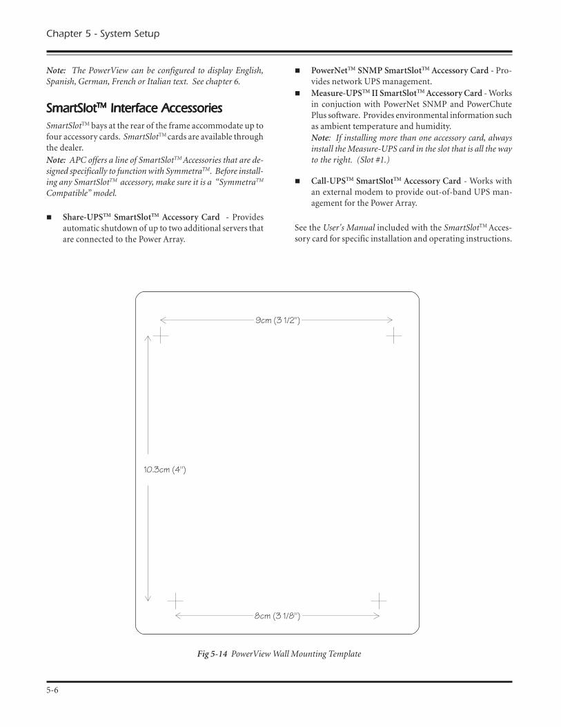
Chapter 5 - System Setup
Note: The PowerView can be configured to display English,Spanish, German, French or Italian text. See chapter 6.
SmartSlotSmartSlotSmartSlotSmartSlotSmartSlotTMTMTMTMTM Interface Accessories Interface Accessories Interface Accessories Interface Accessories Interface AccessoriesSmartSlotTM bays at the rear of the frame accommodate up tofour accessory cards. SmartSlotTM cards are available throughthe dealer.
Note: APC offers a line of SmartSlotTM Accessories that are de-signed specifically to function with SymmetraTM. Before install-ing any SmartSlotTM accessory, make sure it is a �SymmetraTM
Compatible� model.
n Share-UPSTM SmartSlotTM Accessory Card - Providesautomatic shutdown of up to two additional servers thatare connected to the Power Array.
Fig 5-14 PowerView Wall Mounting Template
n PowerNetTM SNMP SmartSlotTM Accessory Card - Pro-vides network UPS management.
n Measure-UPSTM II SmartSlotTM Accessory Card - Worksin conjuction with PowerNet SNMP and PowerChutePlus software. Provides environmental information suchas ambient temperature and humidity.Note: If installing more than one accessory card, alwaysinstall the Measure-UPS card in the slot that is all the wayto the right. (Slot #1.)
n Call-UPSTM SmartSlotTM Accessory Card - Works withan external modem to provide out-of-band UPS man-agement for the Power Array.
See the User's Manual included with the SmartSlotTM Acces-sory card for specific installation and operating instructions.
5-6
8cm (3 1/8")
9cm (3 1/2")
10.3cm (4")

Installation TInstallation TInstallation TInstallation TInstallation TestestestestestNote: This test is intended to verify the correct setup and instal-lation of the SymmetraTM system. It is not intended to explainits usage. In this procedure, you will be instructed to ignorePowerView messages. Refer to chapters 6 & 7 for detailed infor-mation about the operation of SymmetraTM.
The following test procedure is intended to ensure that theMIM, RIM and the power and battery modules have beencorrectly installed. It will verify that the SymmetraTM is re-sponding correctly and is ready to deliver power to the loadequipment. A qualified electrician and/or the installer of theSymmetraTM system should perform this test.
Before this test can be conducted, the main intelligence mod-ule (MIM), the PowerView display, at least one power mod-ule and at least one battery module must be properly installed.Read the installation procedures provided in this chapter.
Installation Test/Checklist
q 1. Make sure all three switches - system enable, mainte-nance bypass, and input circuit breaker - are in the �off� or�standby� position. Make sure all load equipment is eitherturned off or is unplugged from the SymmetraTM .
Note: Load equipment can be left connected during this testprocedure; however, power will be switched �on� and �off� tothe load equipment. Therefore, it is recommended that loadequipment be switched to the �off� position until the comple-tion of this test.
q 2. Switch both the input circuit breaker and the systemenable switch to the �on� position. SymmetraTM will powerup internally but will not deliver output voltage. ThePowerView will display text. Depending on the configura-tion of the SymmetraTM , one or more messages such as �Num-ber of Battery Modules has changed� may appear. Press the�ESC� navigation key until the startup screen appears. Seefigure 5-15. Verify that the input voltage is 220V, 230V or240V nominal, that the output voltage reads �000Vout,� andthat all four of the PowerView LED indicator lights are off.
Fig 5-15 Startup Screen
q 3. From the startup screen, press the �ESC� navigationkey to display the top level menu screen.
Fig 5-16 Top Level Menu & The Enter Navigation Key
Press the down arrow navigation key to select �Status,� andthen press the �Enter� navigation key. The voltage statusscreen appears.
Fig 5-17 Voltage Status Screen
Read the voltage status screen to verify that input voltage (Vin)is nominally either 220V, 230V or 240V. Verify that outputvoltage (Vout) is approximately 0V.
q 4. Press the down arrow key to scroll to the frequencystatus screen. See figure 5-18. Verfiy that the input frequencyis approximately 50 Hz.
Fig 5-18 Frequency Status Screen
q 5. Press the down arrow key to the battery status screen.
Fig 5-19 Battery Status Screen
Verfiy the following:
q The number of battery modules reported (01 in the
example below) is the same as the actual number ofbattery modules that are installed.
q The number of �bad� modules reported is zero.
q A minimum of 90V of battery voltage is reported.
Note: The reported battery voltage will vary from approximately90V to 148V, depending on the state of the battery modulecharge. If the reported voltage is less than 90V, allow the bat-tery modules to recharge. (To recharge the battery modules,leave the system enable switch and the input circuit breaker inthe �on� position, and allow the Power Array to remain idle for30 minutes.)
5-7
Chapter 5 - System Setup

q 6. Press the �Down� arrow key to scroll to the power mod-ule status screen.
Fig 5-20 Power Module Status Screen
Verfiy the following:
q Total �Pwr� modules (power modules) reported isthe same as the actual number of power modulesthat are installed.
q Bad power modules reported is 00 (zero).
q The first line of the power module status screendisplays the reported capacity of the SymmetraTM.The reported capacity is based on the number ofpower modules installed and the size of the frame.See table 5-1 to confirm that the PowerView is
reporting the correct information.
rewoP rewoP rewoP rewoP rewoPseludoM seludoM seludoM seludoM seludoMdellatsnI dellatsnI dellatsnI dellatsnI dellatsnI
detropeR detropeR detropeR detropeR detropeRniyticapaC niyticapaC niyticapaC niyticapaC niyticapaCemarFiniM emarFiniM emarFiniM emarFiniM emarFiniM
detropeR detropeR detropeR detropeR detropeRniyticapaC niyticapaC niyticapaC niyticapaC niyticapaCemarFretsaM emarFretsaM emarFretsaM emarFretsaM emarFretsaM
1 AVk4 AVk4
2 AVk8 AVk8
3 AVk8 AVk21
4 a/n AVk61
5 a/n AVk61
Table 5-1 SymmetraTM Power Module/Frame Capacities
q 7. Press the �Down� arrow key to scroll to the miscella-neous status screen. The bottom line indicates the status ofthe Main Intelligence Module (MIM) and the Redundant In-telligence Module (�RIM). The sample screen in figure 5-21indicates that both are installed and functioning properly(OK). If a module is not installed, the status screen will dis-play the word �NONE.� Confirm that the IM and RIM statusare correct. Use the �ESC� key to return to the startup screen.
Fig 5-21 Miscellaneous Status Screen
q 8. Follow these steps to deliver output voltage to the
load equipment. See figure 5-22 for the screen sequence:Note: It is recommended that load equipment be switched �off�while this step is performed. After output voltage is delivered,switch the load equipment �on.�
q Press the �ESC� key until the startup screen appears.
q Press the �Enter� key to display the top level menu.
q Press the �Down� key until the selection arrow pointsto the �Control� menu item.
q Press the �Enter� key.
q Press the �Down� key, until the selection arrowpoints to �Turn Load ON.�
q Press the �Enter� key.
q Confirm that you want to turn the load on, by
selecting �YES, Turn UPS ON�
q Several other over-ride messages may appear,
depending on the system configuration. Select �StartNow� for any of these startup over-ride messages.
Fig 5-22 Power The Load Sequence
After several seconds, the PowerView display should reportthat the �UPS LOAD IS ON.� Press the �ESC� key to returnto the startup screen. Confirm that output voltage is presentand that the Load On LED indicator is glowing.
Note: The Bypass LED indicator may flash on briefly, and theOn Battery LED indicator may glow for 20-30 seconds if thesystem is configured for �self test at power on.�
q 9. Perform a self test by following the screen sequence infigure 5-23.
Fig 5-23 Initiate a Self Test Sequence
The On Battery LED indicator should glow for approximately30 seconds. A message will appear on the display indicatingthat a self test is in progress. When the �Self Test Complete�message appears, press any key to return to the startup screen.
5-8
Chapter 5 - System Setup

q 10. Place the SymmetraTM into Bypass mode by follow-ing the screen sequence in figure 5-24.
Fig 5-24 Initiate Bypass Mode
The Bypass LED indicator should glow, and the PowerViewdisplay will indicate that the �UPS (SymmetraTM) IS BY-PASSED.�
q 11. Return the SymmetraTM to the On-Line mode of op-eration by following the screen sequence in figure 5-25.
Fig 5-25 Return to On-Line Mode
The Bypass LED indicator should cease to glow, and the mes-sage �UPS IS OUT OF BYPASS� will appear on the PowerViewdisplay. Press any key to return to the startup screen.
q 12. Power down the load equipment by following thescreen sequence in figure 5-26.
Fig 5-26 Power Down the Load Sequence
From the Control menu, power down the load equipment byexecuting the �UPS LOAD OFF� command. After several sec-onds, the �UPS LOAD IS OFF� message is displayed. All LEDindicators on the PowerView should be off.
q 13. Power down the SymmetraTM by switching the sys-tem enable switch and the input circuit breaker to the �standby� position. The installation procedure has now been com-pleted.
Note: This procedure is an installation checklist. Read andfollow the steps in Chapter 7 to configure the SymmetraTM PowerArray for your specific power needs.
Chapter 5 - System Setup
5-9

5-10
Chapter 5 - System Setup

Chapter Six
PowerView Display
This chapter is an overview of the PowerViewuser interface. The PowerView is used to
control the Power Array, configure function-ality, monitor system components, set
alarm thresholds, and to compile and reviewa log of power events. The PowerView pro-
vides the audible and visual alarms that areinitiated when an �alarm event� occurs.
The PowerView can display French, Italian,German, Spanish or English text. Configura-tion instructions are provided at the end of
this chapter.
MiniFrame
MasterFrame

The PowerVThe PowerVThe PowerVThe PowerVThe PowerView User Interiew User Interiew User Interiew User Interiew User InterfacefacefacefacefaceThe PowerView is the primary user interface for the PowerArray system. It is used to control the Power Array, to config-ure the functionality, monitor the system, set alarm thresh-olds, and it provides audible and visual alarms for the sys-tem.
Physical Features of the PowerviewThe PowerView interface incorporates a 4 x 20 alphanumericliquid crystal display (LCD), four navigation keys, four lightemitting diode (LED) indicators, and an audible alarm beeper.It is designed to either mount on the front of the frame, tostand on top of the frame, or to be installed at a remote loca-tion up to 6.1m (20') away. A short RJ45 cable is hardwiredto the top right module bay of the frame. This cable con-nects to the PowerView when it is mounted onto the frame.A 6.1m (20') RJ45 cable is provided for remote installation ofthe PowerView.
Fig 6-1 The PowerView Interface
PowerView FunctionsAn overview of each of the PowerView interface functionsare provided below:
n User Interface - The PowerView is used to command thesystem to power up, and power down the load equip-ment, to review the status of modular and system com-ponents, and to configure functionality of the system.
n Alarms and Alarm Thresholds - In the event of a powerdisturbance, or loss of a system component, (and otheruser-configured alarm conditions), the PowerView in-terface emits both an audible alarm and displays a visualmessage on the LCD screen*. Procedures for setting userconfigurable parameters are provided in Chapter 7. AllPowerView display messages, and the corrective actionsare provided in Chapter 9.
n Set System Function Parameters - The PowerView canbe used to set parameters for the functioning of the PowerArray. These include acceptable input and output fre-quency ranges, frequency of self tests, and minimum/maximum settings for power transfers.
n PowerView Interface Parameters - The PowerView canbe used to set the contrast of the LCD screen, select theinformation that is displayed in the startup screen, setthe time, date, password and the volume of the audiblealarm.
n Event Logging - The 64 most recent power and userevents are recorded and logged into the PowerView in-terface. The interface can be configured to log a specificset or range of data. This data, as well as compiled statis-tics can be reviewed using the PowerView interface.
n Check Status and Diagnostics - Input voltage, outputvoltage, available run time, load size, the present operat-ing mode, and the status of every module in the PowerArray frame can be reviewed using the PowerView inter-face. (See Chapter 7.)
n Testing - The PowerView interface can be used to per-form a system self test and to simulate a power failure.
n Help Function - Pressing the up and down navigationkeys simultaneously launches context sensitive help.
*For example, a Power Array with an N+1 redundancy can beconfigured to emit an audible alarm if the system incurs thelose of a redundant power module. (Typically, this would bethe result of additional load being added, or a power modulefailure.)
Chapter 6 - The PowerView Display
6-1

Chapter 6 - The PowerView Display
6-2
Navigation KeysNavigation KeysNavigation KeysNavigation KeysNavigation KeysThe four navigation keys on the PowerView interface are usedto select and open menu items, to access information, and tochange system parameters. A small "selection arrow" at theleft side of the display screen indicates the menu item or pa-rameter that is selected. The navigation keys are described inTable 6-2.
lobmySyeKno
emaNyeKfo
yeKfonoitcnuF
csEEPACSE stixeyekEPACSEehT
dnaneercstnerrucehtylsuoiverpehtotsnruter
.neercsdeyalpsid
↑ PU ehtsevomyekPUehT.drawpuworranoitceles
↓ NWOD sevomyekNWODehTworranoitceleseht
.drawnwod
↵ RETNE snepoyekRETNEehTro,unemdetceleseht
retemarapasnepo.tsilnoitceles
Table 6-2 PowerView Navigation Keys
PowerVPowerVPowerVPowerVPowerView LED Indicatorsiew LED Indicatorsiew LED Indicatorsiew LED Indicatorsiew LED IndicatorsFour LED indicators report the operational status of the PowerArray. Table 6-1 describes their function.
DEL roloC noitpircseD
NODAOL neerG siyarrArewoPehtsetacidnIenil-noehtnignitarepo
simetsysehT.edomehtmorfrewopgniviecer
sidna,ecruosrewopsniamdenoitidnoc,naelcgniylppus
.tnempiuqedaolotrewop
TTABNO wolleY sniamatahtsetacidnI,derruccosaheruliafrewop
daolehtotrewoptahtdnadeilppusgniebsitnempiuqe
.seludomyrettabehtmorf
SSAPYB wolleY ehtotrewoptahtsetacidnIdeilppusgniebsidaol
sniamehtmorfyltceridrewoPehT.ecruosrewopylevitceffeneebsahyarrA.tiucricehtmorfdevomer
TLUAF deR yarrArewoPehtsetacidnIlanretninadetcetedsahmralanA.noitidnoctluaf
ehtnoraeppalliwegassem.yalpsidDCLweiVrewoP
).9retpahCeeS(
Table 6-1 Power Array Display LEDs

Chapter 6 - The PowerView Display
6-3
The StarThe StarThe StarThe StarThe Startup Scrtup Scrtup Scrtup Scrtup ScreeneeneeneeneenWhen the system enable switch is placed in the �on� position,the �Startup Screen� appears. Figure 6-2 shows the factorydefault startup screen. (The startup screen can be config-ured to display other information.) The factory defaultstartup screen displays the following information:
n Fuel Percentage - The first line indicates the percentageof battery capacity (fuel) that is presently available.
n Load Percentage - The second line indicates the percent-age of system capacity that is being used to supply con-ditioned power to the load equipment.
n Voltage and Input Frequency - The third line indicatesthe input (mains) power voltage, the output voltage sup-plied to the load equipment, and the voltage frequencyof the input (mains) power.
n Run Time - The fourth line indicates the run time thatcan be expected. The intelligence module determinesthe run time based on the amount of power required bythe load equipment, and the power capacity of the bat-tery modules in the Power Array frame.
Note: The PowerView interface will �time out� after ten min-utes of inactivity, and the message on the LCD display will dis-appear. The message will reappear when any navigation key istouched.
Fig 6-2 Startup Screen
The TThe TThe TThe TThe Top-Level Menu Scrop-Level Menu Scrop-Level Menu Scrop-Level Menu Scrop-Level Menu ScreeneeneeneeneenWhen the startup screen is displayed, pressing any of the navi-gation keys will open the �Top-Level Menu� screen. Thisscreen contains seven menu items, and a context sensitive helpfunction. See figure 6-3.
Fig 6-3 Top-Level Menu Screen
The top-level menu screen is similar to a menu bar at the topof a computer interface. Selecting any of the seven menuitems, and pressing the �enter� key opens a sub-menu. Thefunctions of these seven menu items are outlined below.
Note: Many of the following PowerView functions are explainedand demonstrated in Chapter 7.
Controln Power up and power down the load equipmentn Simulate a power failn Conduct a graceful rebootn Conduct a graceful turn offn Start run time calibrationn Put system into or out of bypass mode
Statusn Determine input/output voltage and frequencyn Determine the % load - no redundancyn Determine the % load - with redundancyn Review input/output frequenciesn Review status of battery modulesn Review status of power modulesn Review alarm thresholdsn Determine current operation moden Review status of the main intelligence modulen Review status of the redundant intelligence module

Chapter 6 - The PowerView Display
6-4
Setupn Set the system shutdown parametersn Set the alarm thresholdsn Set input/output voltage frequency synchronization
rangen Set system to go to bypass mode, or not go to bypass
mode, if voltage frequency synchronization is out of anacceptable range when a power module failure occurs
n Set �self test at power up� on or offn Set system IDn Set output voltage to 220V, 230V or 240Vn Copy system settings to another PowerView
Accessoriesn Monitors SmartSlotTM Accessory cards (if present)
Loggingn View the last 64 power or user eventsn Select the events that are to be recorded in the event logn Clear event logn View statistical representation of log datan View logged events by group
Displayn Configure the date and timen Set a passwordn Display the �about system� informationn Set audible alarm parameters and volumesn Set screen contrastn Configure the startup screen
Diagnosticsn Display the reason a failure, change or alarm has occurredn Review status of the main intelligence module (MIM)n Review status of redundant intelligence module (RIM)n Review status of the power modulesn Review status of the battery modules
Helpn The help menu opens online help.
Note: Context sensitive help is available for most screens.Press the up and down navigation keys simultaneously toaccess context sensitive help.
FrFrFrFrFrench, Italian, Gerench, Italian, Gerench, Italian, Gerench, Italian, Gerench, Italian, German or Spanishman or Spanishman or Spanishman or Spanishman or SpanishLanguage ConfigurationLanguage ConfigurationLanguage ConfigurationLanguage ConfigurationLanguage ConfigurationThe factory default PowerView language is English. It can beconfigured to display French, Italian, German or Spanish textby replacing an EPROM (erasable, programmable read onlymemory) chip. A set of replacement EPROM chips are in-cluded with the PowerView. Follow these steps to replace thelanguage EPROM:
Note: The internal circuitry of the PowerView, and the EPROMare sensitive to static electricity. Use all necessary precautionsto eliminate static electricity from yourself and all tools beforereplacing the chip. Do not remove the chip from the protectivecase until you are ready to install it in the PowerView.
n Before disassembling the PowerView, touch a groundedmetal object to thoroughly ground all static charge.
n The PowerView cable must be disconnected from thePowerView before proceeding.
1. Working on a flat table or other suitable work surface, re-move the four Phillips screws at the rear of the PowerView.Separate the back half from the PowerView.
2. Identify the 28-pin language EPROM chip inside thePowerView. See figure 6-4. The EPROM chip is adjacent to alarger 40-pin chip, and is labeled with the name of the lan-guage. Note the semicircular notch at one end of the EPROM.The replacement EPROM must be installed so that the semi-circular notch is in the same orientation.
3. To remove the EPROM, insert a small flathead screwdriverbetween the EPROM and the socket. Gently twist the bladeto lift the EPROM from the socket. To avoid bent pins, pro-ceed with caution and patience. Gradually loosen the chip,one side at a time, until it is free from the socket.
4. Position the replacement EPROM on the socket with thesemicircular notch in the same position as the original.
Important: Carefully check that all pins are properly alignedwith the socket.
5. Apply even pressure with fingers to the top of the EPROMuntil it is fully seated in the socket.
6. Replace the rear cover and re-install the four Phillips screws.
Fig 6-4 EPROM Replacement
LanguageEPROM

Chapter Seven
Configuring & Operatingthe SymmetraTM
This chapter provides the procedure toconfigure the system and to initiate deliveryof conditioned power to the load equipment.Follow these steps to set the configurationvariables and alarm thresholds specifically
for your power management needs.
MiniFrame
MasterFrame

IntrIntrIntrIntrIntroductionoductionoductionoductionoductionThe following pages comprise the inital configuration of theSymmetraTM system. Read and follow these procedures care-fully. When they are completed, the Power Array system willbe configured to provide optimal power protection for thedata center or other load equipment.
The following procedures assume that the Power Array sys-tem is not yet powered. If the Power Array is already pow-ered, check to make sure the load equipment is in a safe stateto be switched off, and then switch the load equipment off.Switch the system enable switch and the input circuit breakerto the �stand by� position. Switch the maintenance bypass tothe �off � position.
Note: Refer to chapter 1 for the location of these switches.
Chapter 7 - Configuring & Operating the SymmetraTM
7-1
Step 1Step 1Step 1Step 1Step 1: Powering the Power Array: Powering the Power Array: Powering the Power Array: Powering the Power Array: Powering the Power ArrayIn this step the Power Array is powered while the load equip-ment remains unpowered.
1. Make sure all input, output and EPO wiring has been in-stalled by a qualified electrican.
Important: Make sure that the electrican has completed theelectrical wiring test/checklist at the end of Chapter 4. Makesure all modules have been installed correctly, that all grillcovers have been replaced onto the frame, and the PowerViewhas been properly connected.
2. Switch the input circuit breaker to the �on� position. ThePower Array is now connected to the mains (utility) powersource.
3. Switch the system enable switch to the �on� position. Thestartup screen will appear on the PowerView interface.
Note: When the system enable switch is switched to the �on�position, the Power Array runs through a series of internal tests.Allow the Power Array to start up for a minimum of 10 secondsbefore entering commands into the PowerView interface.
Fig 7-1 Startup Screen
4. The first line of the startup screen displays the batterycapacity.*The second line displays the load capacity. The load capacityis 000% in this illustration because the load is not poweredyet. The third line displays the input voltage (220Vin), theoutput voltage (000Vout), and the input voltage frequency(50Hz). Again, the output voltage in the illustration is�000Vout� because the load has not been powered.
The fourth line displays the predicted battery run time forthe current load. Until the load is powered, this run time willnot be meaningful.
* There may be some battery discharge during handling andshipping of the Power Array. If batteries are showing less than50% capacity, allow the batteries to charge before proceeding.(To charge battery modules, leave the system enable switch andthe input circuit breaker in the �on� position, and allow thePower Array to remain idle for 30 minutes.)

Step 3Step 3Step 3Step 3Step 3: Review Status Conditions: Review Status Conditions: Review Status Conditions: Review Status Conditions: Review Status ConditionsStatus information about the Power Array and the modularcomponents can be reviewed using the PowerView. Statusinformation is accessed via the �Status� menu item on thetop level menu. Review the following status screens for con-tent.
Position the arrow cursor next to the �Status� menu item onthe top level menu screen. Press the Enter key. The voltagestatus screen appears.
Fig 7-4 Opening the Status Menu Item
Voltage Status Screen
Fig 7-5 Voltage Status Screen
The voltage status screen displays the following information:
Input Voltage (220.1) - the actual input voltage from the util-ity power (mains) source.
Output Voltage (000.0) - the actual output voltage.
Load Current (00.0A) - the amperage drawn by the load.
After the voltage status screen has been reviewed, press theEnter key. The load with redundancy status screen appears.
% Load With No Redundancy StatusScreen
Fig 7-6 Percent Load With No Redundancy Status Screen
% Load Assuming No Redundancy - displays the percent ofthe total Power Array capacity that is required by the load.The total Power Array capacity is defined by the number ofpower modules installed multiplied by 4kVA, and it is lim-ited by the kVA rating of the frame. See table 7-2. After this
Step 2Step 2Step 2Step 2Step 2: Powering the Loads: Powering the Loads: Powering the Loads: Powering the Loads: Powering the Loads1. Use the sequence in figure 7-2 to enter the �Turn LoadOn� command.
Fig 7-2 �Turn Load On� Command Sequence
2. The Power Array has now been instructed to power up theload equipment. It conducts a self diagnosis and determinesif the conditions are safe to deliver power to the load equip-ment. Depending on the diagnostics, the Power Array willeither power the load or one of several startup over-ride mes-sages will appear. A startup over-ride message indicates anexceptional condition exists and gives the option to proceedor abort. An example of a startup over-ride message is dis-played below:
Fig 7-3 Sample Startup Over-Ride Message
For this procedure, select �start now� for any startup over-ride message that may appear.
Note: If an alarm sounds and a �fault message� appears seeChapter 9 for the cause, and the corrective action.
3. When the load has been successfully powered, the green�LOAD ON� LED will glow, and the message �UPS LOAD ISON� will appear on the screen.
Note: The yellow �ON BATT� LED will glow momentarily,while the system is conducting the self test.
4. Press the Escape key and return to the startup screen.
Note: The output voltage now registers on the display, and theload percentage and run time are now based on the actual load.
Chapter 7 - Configuring & Operating the SymmetraTM
7-2

screen has been reviewed, press the Enter key. The percentload with redundancy status screen appears.
% Load With Redundancy Status Screen
Fig 7-7 Percent Load With Redundancy Status Screen
% Load Allowing For Redundancy - displays the percent ofthe non-redundant Power Array capacity that is required bythe load. The non-redundant Power Array capacity is de-fined by the number of user defined non-redundant powermodules installed multiplied by 4kVA, and it is limited bythe kVA rating of the frame. See table 7-1. After the loadwith redundancy status screen has been reviewed, press theEnter key. The frequency status screen appears.
Note: The redundancy level for this measurement is user de-fined and will be assigned in step 6 of this procedure. Eitherzero, one, or two of the power modules will be designated as�redundant.� The remaining power modules are then definedas �non-redundant.�
Table 7-1 Non-Redundant Power Array Capacities
Frequency Status Screen
Fig 7-8 Frequency Status Screen
Frequencies - displays the input frequency that is being re-ceived from the utility power source and the output frequencybeing delivered to the load equipment. After the frequency
status screen has been reviewed, press the Enter key. The bat-tery status screen appears.
Battery Status Screen
Fig 7-9 Battery Status Screen
Battery Status Screen - displays battery voltage, the percent-age of available battery capacity, number of battery modulesthat are installed, number of battery modules that are �bad,�and the predicted run time. Use this screen to check the sta-tus of the battery modules. After the battery status screenhas been reviewed, press the Enter key. The power statusscreen appears.
Note: If a battery module is diagnosed as �bad,� see Chapter 8.
Power Status Screen
Fig 7-10 Sample Power Status Screen
Power Status Screen - the reported Power Array capacity isdependent upon the number of power modules installed andthe size of the frame. Use table 7-2 to confirm that thePowerView is reporting the correct information.
Table 7-2 SymmetraTM Power Module/Frame Capacities
The power status screen also displays the actual level of faulttolerance, the number of power modules installed in theframe, and the number of �bad� power modules.
Fault Tolerance: The actual fault tolerance indicates the num-ber of functioning power modules in the Power Array, minusthe number required to power the load. (i.e., If a load is 6kVA,two modules are required. If five power modules are installed,the fault tolerance will read N+3.) After this screen has beenreviewed, press the Enter key. The alarm threshold statusscreen appears.
Chapter 7 - Configuring & Operating the SymmetraTM
7-3

Step 4Step 4Step 4Step 4Step 4: Per: Per: Per: Per: Perforforforforform a Self Tm a Self Tm a Self Tm a Self Tm a Self TestestestestestA Power Array self test measures system performance by se-quentially placing each power module on battery and thenbriefly placing all of the power modules on battery.
1. The following sequence will initiate a Power Array selftest:
Fig 7-13 Initiate a Self Test Sequence
2. The PowerView displays the message �Self Test In Progress�while the system performs the test.
Note: A series of clicking sounds can be heard during a self test.
3. The PowerView will either report that the self test wascompleted with no errors or will report any failures detected.
4. Press the Escape key and return to the startup screen.
Note: If a power module is diagnosed as �bad,� see Chapter 8.
Alarm Threshold Status Screen
Fig 7-11 Sample Alarm Threshold Status Screen
Alarm Thresholds - The alarm threshold status screen dis-plays the user-defined fault tolerance threshold, the maxi-mum load threshold, and the minimum runtime threshold.
Fault Tolerance: An audible alarm will sound if the level ofredundancy drops below the displayed level.
Load Threshold: An audible alarm will sound if the attachedload exceeds the displayed load threshold.
Runtime: An audible alarm will sound if the predicted runtime becomes less than the displayed minimum runtimethreshold (either because of loss of battery capacity or in-creased load).
After the alarm threshold status screen has been reviewed,press the Enter key. The miscellaneous status screen appears.
Note: These alarm thresholds will be configured for your spe-cific power requirements in step 4.
Miscellaneous Status Screen
Fig 7-12 Sample Miscellaneous Status Screen
The Miscellaneous Status Screen - displays the following in-formation:
Self Test: Displays the results of the last self test that wasperfomed by the Power Array.
Last transfer (Lst Xfr): Displays the reason for the last trans-fer to battery.
Status: Displays the current mode of operation.
Note: See the Introduction Chapter for details about operatingmodes.
IM: Displays the status of the main intelligence module.RIM: Displays status of the redundant intelligence module.
The miscellaneous status screen is the final status screen. Pressthe Escape key to return to the startup screen.
Chapter 7 - Configuring & Operating the SymmetraTM
7-4

Step 6Step 6Step 6Step 6Step 6: Configur: Configur: Configur: Configur: Configure Alare Alare Alare Alare AlarmsmsmsmsmsFollow this procedure to configure the alarm thresholds thatbest fit your specific power requirements.
Use the following sequence on the PowerView to open thealarm thresholds selection screen:
Fig 7-16 Opening the Alarm Thresholds Selection Screen
Alarm Thresholds Selection Screen
Fig 7-17 Alarm Threshold Selection Screen
Each line of the alarm threshold selection screen contains aconfiguration parameter. To set a parameter, select a line andpress the Enter key. Note the flashing up/down arrow ap-pears. Select a desired alarm parameter by scrolling up ordown through the choices using the arrow navigation keys.When the desired parameter is displayed, press the Enter key.The parameter is then recorded into the PowerView memory.
Redundancy Alarm Threshold - The Power Array will signalan alarm if redundancy falls below this threshold. Base thisselection on the number of power modules present (4kVAeach), the size of the load, and the power module redundancyrequirements. If redundant power modules are installed, itis highly recommended that this threshold be set so that thealarm will be initiated if the redundancy is lost (possibly as aresult of an unauthorized increase of the load).
Maximum Load Threshold - The maximum load thresholdcan be set in increments of 2kVA. If the load exceeds thisthreshold, the alarm will sound.
Minimum Run Time Threshold - Select a minimum avail-able run time specifically for your power requirements. Inthe event that the Power View predicts the available run timeis less than this threshold, an alarm will sound.
Switching Audible Alarm Beeper OffUse the following sequence to access the beeper alarm on/offcommand: �Top level menu-Display-Beeper-Vol-select off.�
Note: This procedure silences the audible alarm. It does notresolve the alarm situation.
Step 5Step 5Step 5Step 5Step 5: Configur: Configur: Configur: Configur: Configure Shutdown Parameterse Shutdown Parameterse Shutdown Parameterse Shutdown Parameterse Shutdown ParametersFollow this procedure to configure the shutdown parametersthat best fit your specific power requirements.
The following sequence on the PowerView opens the shut-down parameter selection screen:
Fig 7-14 Shutdown Parameter Selection Sequence
Shutdown Parameter Selection Screen
Fig 7-15 Shutdown Parameter Selection Screen
Each line of the shutdown parameter selection screen con-tains a configuration parameter. To set a parameter, select aline and press the Enter key. Note the flashing up/down ar-row appears. Select the desired parameter by scrolling up ordown through the choices using the Arrow navigation keys.When the desired parameter is displayed, press the Enter key.The parameter is then recorded into the PowerView memory.
Low Battery Duration - When in the on battery mode, thePower Array will signal an alarm 2, 5, 7, or 10 minutes beforesystem shutdown will occur due to battery exhaustion. Makethis selection based on the time that is required to save alldata and switch off the load equipment.
Shutdown Delay - Some computer networks that issue shut-down commands require some additional run time after thatcommand is issued to gracefully shut itself down. If yourcomputer network is one of these, the Power Array providesa choice of a 20, 180, 300, or 600-second delay from the re-ceipt of the shutdown command before the Power Array stopspowering the load equipment.
Return Delay - when utility (mains) power is restored after apower failure, a delay interval may be desirable to allow util-ity power to stabilize before the system goes back on line.The return delay interval choices are 0, 60, 180, or 300 sec-onds.
Return Battery Capacity - When returning from an extendedutility (mains) power failure, a minimum battery capacity isoften desired before repowering the load. The choice of val-ues for this paramer are 0, 10, 25, and 90%. This minimalrequirement ensures there will be sufficient battery run timeto safely shutdown the load in the event of a subsequent powerfailure. Press the Enter key to record your selection, and thenpress the Escape key to return to the startup screen.
Chapter 7 - Configuring & Operating the SymmetraTM
7-5

Step 7Step 7Step 7Step 7Step 7: Review Diagnostic Information: Review Diagnostic Information: Review Diagnostic Information: Review Diagnostic Information: Review Diagnostic InformationThe PowerView allows you to access an extensive set of diag-nostics information. Follow this procedure to review the di-agnostic screens.
The following sequence on the PowerView opens the diag-nostics menu screen:
Fig 7-18 Opening the Diagnostics Menu Screen
Diagnostics Menu Screen
Fig 7-19 Diagnostics Menu Screen
Each line of the diagnostics menu screen contains a menuselection item. Each of these opens a subsequent screen.
Fault & Diagnostics - This menu item displays an overviewof any faults detected within the system. If a fault is detected,the PowerView will display the fault information. Otherwiseit will indicate that no fault was detected.
Intelligence Module - This menu item opens the main intel-ligence module information screen.
Fig 7-20 Main Intelligence Module Information Screen
The status line at the top of this screen indicates if the mainintelligence module is functioning, and it provides detailedinformation about the MIM.
Redundant Intelligence Module - This menu item opens theredundant intelligence module information screen. It ap-pears and functions the same as figure 7-20.
Power Module (Pwr Modules) - This menu item opens thepower module information screen.
Fig 7-21 Power Module Information Screen
With the flashing arrow cursor pointing at the first line (asillustrated in figure 7-21), press the Enter key. The flashingup/down arrow appears. Use the Arrow navigation keys toscroll up or down. The status of each power module will
Chapter 7 - Configuring & Operating the SymmetraTM
7-6
appear. In the event of a power module failure, use this menuitem to identify the failed power module. After a replace-ment power module is installed, use this menu item to con-firm that the new module is recognized by the Power Array,and is functioning properly. (Procedure in Chapter 8.)
Battery Modules (Batts) - This menu item opens the batterymodule information screen.
Fig 7-22 Battery Module Information Screen
With the selection arrow cursor pointing at the second line(as illustrated in figure 7-22), press the Enter key. Note theflashing up/down arrow appears. The status screen for thebattery module in the top battery module bay appears:
Fig 7-23 Top Battery Module Status Screen
This screen indicates that the battery module in bay �R2� isfunctioning properly. Use the Arrow navigation keys to scrollthrough all of the battery module status screens. In the eventof a battery module failure, use this screen to identify thefailed module. After a battery module is replaced, use thisscreen to confirm the new module is recognized by the PowerArray, and is functioning properly. (Procedure in Chapter8.)
Step 8Step 8Step 8Step 8Step 8: Review Logging Menu: Review Logging Menu: Review Logging Menu: Review Logging Menu: Review Logging MenuThe PowerView records the most recent 64 user or powerevents in an electronic log.
The following screen sequence accesses the event log screen:
Fig 7-24 Open the Event Log Sequence
Event Log Screen
Fig 7-25 Event Log Screen
Scroll up or down through the log items using the Arrownavigation keys. The time, date and the number of the selctedlog item is displayed on the top line. For more informationabout a log item, select it, and press the Enter key.

The modular components of the Power Arrayare user replaceable. This chapter provides
procedures for identifying and replacing afailed module. It also provides proceduresfor verifying that a replacement module is
installed and functioning properly.
Chapter Eight
Module Replacement
MiniFrame
MasterFrame

Module ReplacementThe battery and power modules and the main intelligenceand redundant intelligence modules are user replaceable. Ifa power or main intelligence module fails and a �redundant�module is present, the failed module can be replaced withoutinterrupting power to the load equipment.
Note: A redundant intelligence module can be replaced with-out interrupting power to the load, provided a functioning MIMis installed. A battery module can be replaced without inter-rupting power to the load, provided the Power Array is not inthe on-battery operating mode.
Module FailurModule FailurModule FailurModule FailurModule Failure Alare Alare Alare Alare Alarm Indicatorsm Indicatorsm Indicatorsm Indicatorsm IndicatorsIn the event of a module failure, the PowerView will displayone of the module failure messages in figures 8-1 through 8-4, and the red Fault LED status indicator will glow. ThePowerView audible alarm, a pager notification, and/or soft-ware notification may also be initiated.
Fig 8-1 Battery Module Failure Message
Fig 8-2 Power Module Failure Message
Fig 8-3 Intelligence Module Failure Message
Fig 8-4 Redundant Intelligence Module Failure Message
The power and battery module failure messages identify thebay where the module is installed. Bay locations (L1, L2, etc.or R2, R3, etc.) are printed on the center spine of the frame,between the module bays.
TTTTTechnical Supporechnical Supporechnical Supporechnical Supporechnical Support & Obtainingt & Obtainingt & Obtainingt & Obtainingt & ObtainingReplacement ModuleReplacement ModuleReplacement ModuleReplacement ModuleReplacement ModuleTo obtain a replacement module or for technical assistance,contact APC technical support. A technician can help diag-nose a problem over the telephone and can facilitate obtain-ing replacement modules.* When contacting APC, be pre-pared with the following information:n In the event of a module failure, the PowerView may dis-
play additional �fault list� screens. Press any key to scrollthrough these fault lists, record the information, and relayit to the the technical support technician.
n If possible, call APC technical support from a telephonethat is within reach of the SymmetraTM PowerView. Thiswill aid in using the PowerView to gather and report addi-tional information to the technician.
n Be prepared to provide a detailed description of the prob-lem. A technician will help you solve the problem over thetelephone if possible or will give you a Return MaterialAuthorizaton Number (RMA#). If a module is returnedto APC, this RMA# must be clearly printed on the outsideof the package.
n If the SymmetraTM is within the warranty period, repairswill be performed free of charge. If it is not within thewarranty period, there will be a charge for repair.
n If the SymmetraTM is covered by an APC PowerPlan Ser-vice Product, have that information available to give to thetechnical support technician.
Returning Modules to APCTo return a failed module to APC, pack the module in theoriginal shipping container, and return it by insured, prepaidcarrier. The APC technician will provide the address. If youno longer have the original shipping materials, ask the tech-nician about obtaining a new set. It is very important thatyou pack the module properly to avoid damage in transit.Never use stryrofoam beads or other loose packaging mate-rials when shipping a module. The module may settle in tran-sit and become damaged. Enclose a letter in the package withyour name, RMA#, address, a copy of the sales receipt, de-scription of the trouble, a phone number, and a check (ifnecessary.)
Note: Damages sustained in transit are not covered under war-ranty.
Chapter 8 - Module Replacement
8-1
*If a service contract was purchased from another service pro-vider, contact the service provider for replacement modulesand technical assistance.

BatterBatterBatterBatterBattery Module Replacementy Module Replacementy Module Replacementy Module Replacementy Module Replacement
n The battery module weighs approx. 60 lbs. When re-moving or installing a battery module, two people arerequired to lift the battery module.
1. Remove the appropriate grill cover. The battery modulebays are labeled on the center spine behind the grill covers.
2. Battery modules are designed with a �drop lock� that holdsthem securely in the frame. Slightly lift the front handle ofthe battery module, and pull it forward to the safety stop.
3. With one person on either side of the battery module, liftand remove the battery module from the frame.
Note: The safety stop retaining flange passes through the notchin the frame as the battery module is removed. See figure 8-5.
Fig 8-5 Battery Module Retaining Flange
4. To dispose of the battery module, return it to the appro-priate service provider or directly to APC for recycyling.
Note: The battery module contains sealed, non-spillable leadacid batteries. These must be recycled or disposed of properly.
Installing the Replacement ModuleRefer to Chapter 5 for the battery module installation proce-dure.
8-2
Chapter 8 - Module Replacement
Replacement Battery Module VerificationFrom the startup screen, press any key to open the top levelmenu screen. Follow the sequence in figure 8-6 to ensurethat the new battery module is recognized by the Power Ar-ray system and is functioning properly. (Status: OK).
Fig 8-6 Replacement Battery Module Verification
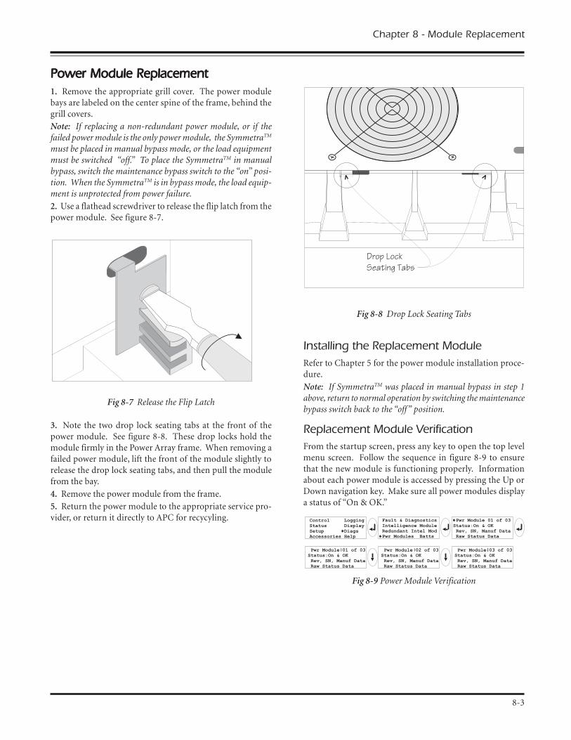
Power Module ReplacementPower Module ReplacementPower Module ReplacementPower Module ReplacementPower Module Replacement1. Remove the appropriate grill cover. The power modulebays are labeled on the center spine of the frame, behind thegrill covers.
Note: If replacing a non-redundant power module, or if thefailed power module is the only power module, the SymmetraTM
must be placed in manual bypass mode, or the load equipmentmust be switched �off.� To place the SymmetraTM in manualbypass, switch the maintenance bypass switch to the �on� posi-tion. When the SymmetraTM is in bypass mode, the load equip-ment is unprotected from power failure.
2. Use a flathead screwdriver to release the flip latch from thepower module. See figure 8-7.
Fig 8-7 Release the Flip Latch
3. Note the two drop lock seating tabs at the front of thepower module. See figure 8-8. These drop locks hold themodule firmly in the Power Array frame. When removing afailed power module, lift the front of the module slightly torelease the drop lock seating tabs, and then pull the modulefrom the bay.
4. Remove the power module from the frame.
5. Return the power module to the appropriate service pro-vider, or return it directly to APC for recycyling.
Chapter 8 - Module Replacement
8-3
Fig 8-8 Drop Lock Seating Tabs
Installing the Replacement ModuleRefer to Chapter 5 for the power module installation proce-dure.
Note: If SymmetraTM was placed in manual bypass in step 1above, return to normal operation by switching the maintenancebypass switch back to the �off� position.
Replacement Module VerificationFrom the startup screen, press any key to open the top levelmenu screen. Follow the sequence in figure 8-9 to ensurethat the new module is functioning properly. Informationabout each power module is accessed by pressing the Up orDown navigation key. Make sure all power modules displaya status of �On & OK.�
Fig 8-9 Power Module Verification
Drop LockSeating Tabs

8-4
Chapter 8 - Module Replacement
Main Intelligence Module ReplacementMain Intelligence Module ReplacementMain Intelligence Module ReplacementMain Intelligence Module ReplacementMain Intelligence Module Replacement1. Remove the grill cover from the top level of the Power Array.
The intelligence module resides under the redundant intelligencemodule in the upper right corner of the frame.
Note: If a functioning RIM is installed, it will provide limitedcontrol of the SymmetraTM until the replacement MIM is installed.If a functioning RIM is not installed, either the SymmetraTM mustbe placed in manual bypass mode or the load equipment must beswitched off. To place the SymmetraTM in manual bypass, switchthe maintenance bypass switch to the �on� position.
Important: When the SymmetraTM is in bypass mode, the loadequipment is unprotected from power failure.
2. Use a flathead screwdriver to release the flip latch.
3. Unscrew and release the retaining screws.
4. Slide the MIM out of the frame.
Installing the Replacement Main IntelligenceModuleRefer to Chapter 5 for the MIM installation procedure.
Note: If SymmetraTM was placed in manual bypass in step 1 above,return to normal operation by switching the maintenance bypassswitch back to the �off� position.
Replacement MIM VerificationFrom the startup screen, press any key to open the top level menuscreen. Follow the sequence in figure 8-10 to ensure that thereplacement MIM is functioning properly. (Status: On & OK).
Fig 8-10 Intelligence Module Verification
Redundant Intelligence ModuleRedundant Intelligence ModuleRedundant Intelligence ModuleRedundant Intelligence ModuleRedundant Intelligence ModuleReplacementReplacementReplacementReplacementReplacement1. Remove the grill cover from the top level of the Power Array.
The redundant intelligence module resides above the intelligencemodule in the upper right corner of the frame.
Note. A RIM can only be replaced if a functioning MIM is in-stalled or the load equipment is switched off.
2. Use a flathead screwdriver to release the flip latch.
3. Unscrew and release the retaining screws.
4. Slide the RIM out of the frame.
Installing the Replacement RedundantIntelligence ModuleRefer to Chapter 5 for the RIM installation procedure.
Note: A RIM alone is not adequate to restart the SymmetraTM.Make sure a functioning MIM is installed.
Replacement Redundant Intelligene ModuleVerificationFrom the startup screen, press any key to open the top level menuscreen. Follow the sequence in figure 8-11 to ensure that thereplacement RIM is functioning properly. (Status: On & OK).
Fig 8-11 Redundant Intelligence Module Verification

The PowerView reports various messages on thedisplay, including alarm status and changes in
system configuration. This chapter lists allPowerView display messages, it describes whateach of them means, and it provides an appro-
priate corrective action (if necessary).
Note: More than one of these messages mayoccur at one time. If this happens, be sure toreview all of the messages for a better under-
standing of the system condition.
Chapter Nine
PowerView Interface Messages
MiniFrame
MasterFrame

weiVrewoP weiVrewoP weiVrewoP weiVrewoP weiVrewoPegasseM egasseM egasseM egasseM egasseM
gninaeM gninaeM gninaeM gninaeM gninaeM noitcAevitcerroC noitcAevitcerroC noitcAevitcerroC noitcAevitcerroC noitcAevitcerroC
pU-tratS pU-tratS pU-tratS pU-tratS pU-tratS degnahcseludomrwP#.NOtsalecnis
saheludomrewopenotsaeltAmorfdevomerro,deddaneeb
artemmySeht MT tsalehtecnisdnammocNOrwPehtemit
.deussisaw
.yrassecennoitcaevitcerrocoN.putratsehthtiwdeecorP
ecnisdegnahcseirettaB#.NOtsal
eludomyrettabenotsaeltAdevomerro,deddaneebsah
artemmySehtmorf MT ecnisNOrwPehtemittsaleht
.deussisawdnammoc
.yrassecennoitcaevitcerrocoN.putratsehthtiwdeecorP
tnadnudeRoN.eludoMecnegilletnI
.dellatsniMIRonsierehTetoN semitemosegassemsihT:
purewoptasrucco ehtesuaceberofebMIRehtstcetedMIM
".ekawa"siMIReht
trobaro,putratsehthtiwdeecorP.MIRallatsnidna,putratseht
:etoN ,MIRgninoitcnufatuohtiWtneveehtniycnadnuderonsiereht
.eruliafMIMafo
nahtsselyticapacttaBpaCttaBnruteR
ehtfoyticapacyrettabehTartemmyS MT ehtnahtsselsi
muminimdeificepsresuotderiuqeryticapacyrettab
.daolehtnonrut
1#noitpO dna,putratsehttrobA:.egrahcerotseirettabwolla
2#noitpO ,putratseunitnoC:yrettabmuminimnahtsselhtiw
.yticapac
edistuoqerFtupnIegnarderugifnoc
ehtotycneuqerftupniehTartemmyS MT ehtedistuosi
tuptuoehT.egnarderugifnoctonlliwycneuqerf
tupniehthtiwezinorhcnyssissapyblamroN.ycneuqerf
.elbaliavaton
1#noitpO ehtevorpmI:.egatlovgnimocniehtfoycneuqerf
2#noitpO foegnarehtnediW:gnimocnielbatpeccaeht
.weiVrewoPehthtiwycneuqerf.tceleS-qerFtuptuO-puteS-putratS( )
3#noitpO .putratshtiwdeecorP:.elbaliavatonsissapyblamroN
SPUrofetauqedaCAssapybroftontub
artemmySehT MT noitcnuflliw,egatlovtupniehthtiwenilnosissapybtahttneveehtnitub
siegatlovtupnieht,deriuqerehtrewopotetauqedaton
.tnempiuqedaol
1#noitpO gnimocniehtevorpmI:.egatlov
noitpO 2# .putratshtiwdeecorP:.elbaliavatonsissapyblamroN
,tupniCAoN/woLyrettabnoputrats
etauqedatonsiegatlovtupnIartemmySehttratsot MT fI.
artemmyS,sdeecorpputrats MT
.yrettabmorfnoitcnuflliw
1#noitpO litnuputratstrobA:.tneserpsiegatlovtupnielbatpecca
2#noitpO .putratshtiwdeecorP:.degrahcsideblliwyrettaB
Chapter 9 - PowerView Display Messages
9-1

weiVrewoP weiVrewoP weiVrewoP weiVrewoP weiVrewoPegasseM egasseM egasseM egasseM egasseM
gninaeM gninaeM gninaeM gninaeM gninaeM noitcAevitcerroC noitcAevitcerroC noitcAevitcerroC noitcAevitcerroC noitcAevitcerroC
lareneG lareneG lareneG lareneG lareneGsutatS sutatS sutatS sutatS sutatS
.desaercniseirettabfo#saheludomyrettabenotsaeltA
.metsysehtotdeddaneeb.yrassecennoitcaevitcerrocoN
.desaercedseirettabfo#saheludomyrettabenotsaeltA.metsysehtmorfdevomerneeb
.yrassecennoitcaevitcerrocoN
seludoMrwPfo#.desaercni
saheludomrewopenotsaeltA.metsysehtotdeddaneeb
.yrassecennoitcaevitcerrocoN
seludoMrwPfo#.desaerced
saheludomrewopenotsaeltA.metsysehtmorfdevomerneeb
.yrassecennoitcaevitcerrocoN
eludoMecnegilletnI.detresni
otnidellatsnineebsahMIMAartemmySeht MT .
.yrassecennoitcaevitcerrocoN
eludoMecnegilletnIdevomer
morfdevomerneebsahMIMAartemmySeht MT .
.yrassecennoitcaevitcerrocoN
ecnegilletnItnadnudeR.detresnieludoM
ehtotnidellatsnineebsahMIRAartemmyS MT .
.yrassecennoitcaevitcerrocoN
ecmegilletnItnadnudeR.devomereludoM
morfdevomerneebsahMIRAartemmySeht MT .
.yrassecennoitcaevitcerrocoN
yrettaBlanretxEfo#.desaercnistenibaC
yrettablanretxeenotsaeltAotdetcennocneebsahtenibac
.emarfeht.yrassecennoitcaevitcerrocoN
yrettaBlanretxEfo#.desaercedstenibaC
yrettablanretxeenotsaeltAdetcennocsidneebsahstenibac
artemmySehtmorf MT ..yrassecennoitcaevitcerrocoN
derotseRycnadnudeR
eludomrewopfossolAsahdna,derruccoycnadnuder
lanoitiddarehtiE.derotserneebro,dellatsnineebevahseludom
.decuderneebsahdaoleht
.yrassecennoitcaevitcerrocoN
evobaregnoLoNsidaoLdlohserhTmralA
daolehtdedeecxedahdaolehTnoitautisehT.dlohserhtmrala
esuacebrehtiedetcerrocneebsahehtro,desaerceddaoleht
.desaercnisawdlohserht
.yrassecennoitcaevitcerrocoN
.derotseremitnuRniM
depporddahemitnurmetsysehT,muminimderugifnocehtwoleb
rehtiE.derotserneebsahdnaerewseludomyrettablanoitidda
yrettabgnitsixeeht,dellatsnisawdaoleht,degrahcerseludom
sawdlohserhtehtro,decuder.desiar
.yrassecennoitcaevitcerrocoN
9-2
Chapter 9 - PowerView Display Messages

weiVrewoP weiVrewoP weiVrewoP weiVrewoP weiVrewoPegasseM egasseM egasseM egasseM egasseM
gninaeM gninaeM gninaeM gninaeM gninaeM noitcAevitcerroC noitcAevitcerroC noitcAevitcerroC noitcAevitcerroC noitcAevitcerroC
eludoM eludoM eludoM eludoM eludoMeruliaF eruliaF eruliaF eruliaF eruliaF
eludoMyrettaBdaB,deliafsaheludomyrettabA
.tnemecalperseriuqerdnaeludomrof8retpahCotrefeR
.erudecorptnemecalper
eludoMrewoPdaB,deliafsaheludomrewopA
.tnemecalperseriuqerdnaeludomrof8retpahCotrefeR
.erudecorptnemecalper
sieludoMecnegilletnIdeliafdnadellatsni
eludomecnegilletniniamehTseriuqerdna,deliafsah
.tnemecalper
eludomrof8retpahCotrefeR.erudecorptnemecalper
ecnegilletnItnadnudeRdnadellatsnisieludoM
deliaf
ecnegilletnitnadnuderehTdna,deliafsaheludom.tnemecalperseriuqer
eludomrof8retpahCotrefeR.erudecorptnemecalper
dlohserhT dlohserhT dlohserhT dlohserhT dlohserhTmralA mralA mralA mralA mralA
mralaAVkevobasidaoLdlohserht
ehtdedeecxesahdaolehTmraladaoldeificepsresu
.dlohserht
1#noitpO .daolehtecudeR:2#noitpO otweiVrewoPehtesU:
.dlohserhtmralaehtesiar
neebsahycnadnudeR.tsol
artemmyS MT stcetedregnolon.seludomrewoptnadnuder
evah)s(eludomrewoprehtiEsahdaolehtro,deliaf
.desaercni
1#noitpO llatsni,elbissopfI:.seludomrewoplanoitidda
2#noitpO .daolehtesaerceD:3#noitpO ehtelbasiD:
gnittesybmralaycnadnuder.orezotycnadnuder -putratS(
-ycnadnudeR-smralA-puteSoreztceles ).
wolebsiycnadnudeR.dlohserhtmrala
eludomrewoplautcAwolebnellafsahycnadnuder
ycnadnuderdeificepsresuehtrehtiE.dlohserhtmrala
,deliafevah)s(eludomrewop.desaercnisahdaolehtro
1#noitpO llatsni,elbissopfI:.seludomrewoplanoitidda
2#noitpO .daolehtesaerceD:3#noitpO otweiVrewoPehtesU:
mralaycnadnuderehtesaerced(.dlohserht -smralA-puteS-putratS
tceles-ycnadnudeR ).
mralawolebsiemitnuR.dlohserht
siemitnurdetciderpehTdeificepsresuehtnahtrewol
mralaemitnurmuminimyrettabehtrehtiE.dlohserhtehtro,desaercedsahyticapac
.desaercnisahdaol
1#noitpO yrettabehtwollA:.egrahcerotseludom
2#noitpO esaercni,elbissopfI:.seludomyrettabforebmuneht
3#noitpO .daolehtesaerceD:4#noitpO otweiVrewoPehtesU:
emitnurmuminimehtesaerced-puteS-putratS(.dlohserhtmrala
).tceles-emitnuR-smralA
ssapyB ssapyB ssapyB ssapyB ssapyB
egnarnitonsissapyB)egatlovroqerfrehtie(
egatlovro/dnaycneuqerfehTrofegnarelbatpeccafotuosisruccoegassemsihT.ssapyb
artemmySnehw MT ,enilnosissapybehttahtsetacidnidnafielbaliavaebtonyamedom
.deriuqer
1#noitpO ehtesaerceD:.ycneuqerftupniotytivitisnes
( .tceles-qerFtuptuO-puteS-putratS )2#noitpO egatlovtupnitcerrroC:
egatlovelbatpeccaedivorpot.ycneuqerfro/dna
kcutsrotcatnocssapyB.noitisopssapybni
artemmyS MT ehtnikcutssiogtonnacdna,noitisopssapyb
.enilno
ecivrestcartnocruoyllaClacinhceTCPAro,redivorp
).revoctnorfedisnieeS(.troppuS
Chapter 9 - PowerView Display Messages
9-3

weiVrewoP weiVrewoP weiVrewoP weiVrewoP weiVrewoPegasseM egasseM egasseM egasseM egasseM
gninaeM gninaeM gninaeM gninaeM gninaeM noitcAevitcerroC noitcAevitcerroC noitcAevitcerroC noitcAevitcerroC noitcAevitcerroC
ssapyB ssapyB ssapyB ssapyB ssapyB kcutsrotcatnocssapyB.noitisopenil-noni
artemmyS MT ehtnikcutssitonnacdna,noitisopenil-no
.ssapybotog
ecivrestcartnocruoyllaClacinhceTCPAro,redivorp
).revoctnorfedisnieeS(.troppuS
oteudssapybniSPU.tluaflanretni
artemmyS MT otderrefsnartsahtluafaesuacebedomssapyb
uccosah r .der
ecivrestcartnocruoyllaClacinhceTCPAro,redivorp
).revoctnorfedisnieeS(.troppuS
oteudssapybniSPUdaolrevo
ehtdedeecxesahdaolehTehT.yticapacrewopmetsys
artemmyS MT otdehctiwssah.edomssapyb
1#noitpO .daolehtesaerceD:2#noitpO rewopdda,elbissopfI:
.metsysehtotseludom
nisimetsySssapyBecnanetniaM
artemmySehT MT ssapybnisiecnanetniamehtesuaceb
"no"ehtnisihctiwsssapyb.noitisop
.yrassecennoitcaevitcerrocoN
lareneG lareneG lareneG lareneG lareneGtluaF tluaF tluaF tluaF tluaF
yrettaBnO ehT artemmyS MT noehtnisi.noitarepofoedomyrettab
gnieberaseludomyrettabehT.degrahcsid
.yrassecennoitcaevitcerrocoN:etoN nidetimilsiemitnuR
ehtnwodtuhsoteraperP.noitarudartemmyS MT daolehtdna
gnimocnierotserro,tnempiuqe.egatlov
tnemecalpeRtaBdeeN seludomyrettaberomroenO.tnemecalperfodeenniera
eludomrof8retpahCotrefeR.serudecorptnemecalper
tluaFSPU aniderruccosahtluafAlliwsihT.eludomrewop
dabahtiwruccosyawlaeruliafeludomrewop
.egassem
ecivrestcartnocruoyllaClacinhceTCPAro,redivorp
).revoctnorfedisnieeS(.troppuS
otelbanuronwodtuhSoteudttaBotrefsnart
daolrevo
artemmyS MT nwodtuhssahsahdaolrevonaesuaceb
tonsissapybdnaderrucco.elbaliava
1#noitpO otdaolehtecudeR:.daolrevoetanimile
2#noitpO rewopdda,elbissopfI:.daolrevoetanimileotseludom
3#noitpO rewopdeliafecalpeR:.daolrevoetanimileotseludom
:etoN elbaliavatonsissapybfIroftiaw,eruliafrewopafoesuaceb
asierehtfI.derotserebotrewop,melborpytilitu evah .detcerrocti
morfnwodtuhSdaoLstloV/qerFtupnI.ssapyB
.stimiledistuo
artemmyS MT daolehttuhssah,ssapybnosawtielihwnwodtnewrewoptupniehtesuaceb
.egnarelbatpeccafotuo
egatlovtupniehttcerroC.melborp
regrahCyrettaB,tluaFeruliaF
roenoniregrahcyrettabehT.deliaf)s(eludomrewoperom
retpahCotrefeR 8 eludomrof.serudecorptnemecalper
yaleRssapyB,tluaFnoitcnuflaM
sahyalerssapybehT.denoitcnuflam
ecivrestcartnocruoyllaClacinhceTCPAro,redivorp
).revoctnorfedisnieeS(.troppuS
9-4
Chapter 9 - PowerView Display Messages

weiVrewoP weiVrewoP weiVrewoP weiVrewoP weiVrewoPegasseM egasseM egasseM egasseM egasseM
gninaeM gninaeM gninaeM gninaeM gninaeM noitcAevitcerroC noitcAevitcerroC noitcAevitcerroC noitcAevitcerroC noitcAevitcerroC
lareneG lareneG lareneG lareneG lareneGtluaF tluaF tluaF tluaF tluaF
pmeTlanretnI,tluaFstimillamrondedeecxe
roenofoerutarepmetehTootsiseludomyrettaberom
.toh
.seludomdetaehrevoehtecalpeReludomrof8retpahCotrefeR
.serudecorptnemecalper
rekaerbtiucrictupnInepodeppirt
norekaerbtiucrictupniehTartemmySeht MT .deppirtsah
detcennocsidsiegatlovtupnIartemmySehtot MT .
1#noitpO nisruccosihtfI:daolrevonahtiwnoitcnujnoc
dnadaolehtesaerced,noitidnoc.rekaerbehtteser
1#noitpO daolrevoonfI:fI.rekaerbteser,stsixenoitidnoc
tcartnocruoyllac,niagaspirttilacinhceTCPAro,redivorpecivres
).revoctnorfedisnieeS(.troppuS
deliafnaflevelmetsyS ehtninafgniloocAartemmyS MT .deliafsahemarf
ecivrestcartnocruoyllaClacinhceTCPAro,redivorp
).revoctnorfedisnieeS(.troppuS
tnadnudeRehTnisieludoMecnegilletnI
lortnoc
eludomecnegilletniniamehTsiMIRehtdna,deliafsahyramirpehtsagninoitcnuf
.eludomecnegilletni
ecnegilletniniamehtecalpeRrof8retpahCotrefeR.eludom.serudecorptnemecalpereludom
eludom-retniCII.deliafsnoitacinummoc
neewtebsnoitacinummocehTenotsaeltadnaMIMeht
.deliafsaheludomrehto
ecivrestcartnocruoyllaClacinhceTCPAro,redivorp
).revoctnorfedisnieeS(.troppuS
Chapter 9 - PowerView Display Messages
9-5

9-6
Chapter 9 - PowerView Display Messages

A comprehensive indexof all terms and concepts
Index
MiniFrame
MasterFrame

Index
AAlarms
Configuring, 7-5PowerView, 6-1Threshold status, 7-4
Audible alarm, silencing, 7-5
BBattery, Extended Run Connector
Description, 1-4
Battery modulesDescription, 1-2Installation, 5-2Ordering replacement, 8-1Replacement procedure, 8-2Verification, 8-2
BTU output, 2-1Bypass Operating mode, i
CCapacity definition (v)
DDiagnostics screens
Battery module, 7-6Fault & diagnostics, 7-6Intelligence module, 7-6Power module, 7-6Redundant intelligence, 7-6
DimensionsFrame, 2-1, 3-1Modules, 3-1
EElectro-static discharge, 2-1Emergency power off, 4-5
FFootprint, 2-1Frame
Capacity, (v), 5-8Description, 1-1, 1-4Footprint, 2-1Leveling, 5-1Pallet, 3-1Size, 2-1Weight, 2-1
GGrill covers, 1-2, 5-1
HHot-swappable definiton (v)Humidity range, 2-1
IInput wiring, 4-2Installation checklist, 5-7Input circuit breaker
Description, 1-3
LLoad-Disconnect mode, iLog, 7-6Low battery duration, 7-5
MMain intelligence module,
Description, 1-3Installation, 5-4Ordering information, 8-1Replacement procedure, 8-4Verification, 8-4
Maintenance bypass switchDescription, 1-3
Maximum load threshold, 7-5Minimum run time threshold, 7-5Modes of operation, (iii)Module failure alarms, 8-1
NN+1 definition, (v)
OOn-Battery Operating mode, iOn-Line Operating mode, iOperating conditions, 2-1Operating modes, iOutput wiring, 4-4

Index
PPackaging, 3-1Power off procedure, safety-1Power module
Description, 1-2Installation, 5-3Ordering information, 8-1Replacement procedure, 8-3Verification, 8-3
Powering the loads, 7-2Powering the SymmetraTM, 7-1PowerView display
Description, 1-2, chapter 6Installation, 5-5LED indicators, 6-2Navigation keys, 6-2Ordering information, 8-1Remote installation, 5-5Startup screen, 6-3Top level menu, 6-3Wall mounting, 5-5
RRedundancy alarm threshold, 7-5Redundancy definition (v)Redundant intelligence module
Description, 1-3Installation, 5-4Ordering information, 8-1Replacement procedure, 8-4Verification, 8-4
Replacement modules, 8-1REPO, 4-5Return battery capacity, 7-5Return delay, 7-5Returning modules to APC, 8-1
SSelf test, 7-4Shutdown delay, 7-5Shutdown parameters
Configuring, 7-5SmartSlot accessories
Description, 1-4, 5-6Installation, 5-6Ordering information, 5-6
Status screens,Alarm threshold status screen, 7-4Battery status screen, 7-3Frequency status screen, 7-3Miscellaneous status screen, 7-4Percent load status screens, 7-3Power status screen, 7-3Voltage status screen, 7-2
System Enable SwitchDescription, 1-4
TTechnical support, 8-1Temperature range, 2-1Theory of operation, (i)
WWeights
Frame, 2-1, 3-1Modules, 3-1
WiringChecklist, 4-6Input, 4-2Output, 4-4Overview, 4-1
REPO, 4-5
Wiring GaugeInput, 4-2Output, 4-4

SymmetraSymmetraSymmetraSymmetraSymmetraTMTMTMTMTM Power Array Dealers: Power Array Dealers: Power Array Dealers: Power Array Dealers: Power Array Dealers:(Replacement Modules & Accessories)(Replacement Modules & Accessories)(Replacement Modules & Accessories)(Replacement Modules & Accessories)(Replacement Modules & Accessories)
APC EuropeAPC Europe HeadquartersBallybrit Business ParkGalway, IrelandTelephone ...... +353 91 702000Fax ................. +353 91 756909
APC BalkansTelephone ...... +33 1 64625926Fax ................. +33 1 60176551
APC BeneluxTelephone ...... +31 183 628 898Fax ................. +31 183 628 821
APC Czech & Slovak RepublicTelephone ...... +420 2 683 7845Fax ................. +420 2 683 7680
APC FranceTelephone ...... +33 1 41 90 52 00
+0800 39 32 03Fax ................. +33 1 41 90 52 88
APC GermanyTelephone ...... +49 89 51417 0Fax ................. +49 89 51417 100
APC HungaryTelephone ...... +36 1 2696433Fax ................. +36 1 2696433
APC ItalyTelephone ...... +39 229 40 55 08Fax ................. +39 229 40 55 15
APC MoscowTelephone ...... +7 095 929 90 95Fax ................. +7 095 929 91 80
APC NordicTelephone ...... +46 8 6429710Fax ................. +46 8 6424727
APC NovosibirskTelephone ...... +7 3832 32 00 05Fax ................. +7 3832 39 75 75
APC PolandTelephone ...... +48 22 666 00 11Fax ................. +48 22 666 00 22Infoline .......... 0 800 25252
APC Spain & PortugalTelephone ...... +34 3 4127125
+34 3 3180133Fax ................. +34 3 4127125
+34 3 3177646
APC TurkeyTelephone ...... +90 212 230 7156Fax ................. +90 212 230 7113
APC UkraineTelephone ...... +380 44 2969409Fax ................. +380 44 2955292
APC United KingdomTelephone ...... +44 1753 511 022Fax ................. +44 1753 511 033
APC E-Mail & InternetInternet ......... http://www.apcc.comE-Mail ............ [email protected]

Please note: The PowerView messages in Chapter 9 offer solutions for most difficul-ties you may encounter with the SymmetraTM. Before calling Technical Support,
please record the following serial numbers below:
Frame Serial #:
PowerView Serial #:
Main Intelligence Module Serial #:
Redundant Intelligence Module Serial #:
Power Module Serial #�s:
Battery Module Serial #�s:
(L1)
(L2)
(L3)
(L4)
(L5)
(R2)
(R3)
(R4)
(R5)
990-7779 Rev.1 ~ English
English Text