entellisystm low voltage switchgear...entellisys low voltage switchgear 5 2. receiving, handling,...
TRANSCRIPT

1
EntellisysTM Low Voltage Switchgear
Installation and Maintenance Instructions DEH 537
with EntelliGuard E Low Voltage Power
Circuit Breakers
2
1. Introduction 3
1-1 General Information 3
1-2 Instruction Book Arrangement 3
1-3 Related Publications 3
2. Receiving, Handling, and Storage 5
2-1 Receiving 5
2-2 Handling 6
2-3 Storage 9
3. Description 10
3-1 General 10
3-2 Summary Description 10
3-3 Front Compartment Area 12
3-4 EntelliGuard Messenger 12
3-5 Breaker Compartment 12
3-6 Circuit Breakers 16
3-7 Compartments for Future Breakers 17
3-8 Auxiliary/Transition Sections 17
3-9 Bus Area 17
3-10 Feeder Cable and Busway Compartment 19
3-11 Ground Bus 20
4. Equipment Installation 21
4-1 General 21
4-2 Assembly and Installation of Switchgear Equipment 24
4-3 Installation of Wall-Mount HMI 35
5. Installing & Removing Circuit Breakers 37
5-1 General 37
5-2 Installing EntelliGuard G Circuit Breakers 38
5-3 Removing the EntelliGuard E Circuit Breakers 39
6. Testing & Inspection 40
6-1 General 40
6-2 Key Interlocks 40
6-3 Breaker Operation Test 40
6-4 Entellisys System Test Kit 40
6-5 Final Steps to Be Taken Before Energizing Equipment 40
7. Operating the Switchgear 42
7-1 Circuit Breaker Operation 42
7-2 Circuit Breaker Drawout 42
7-3 Front Doors 43
7-4 Entellisys Switchgear Accessories 43
8. Energizing the Switchgear 47
8-1 Before Energizing 47
8-2 Energizing Procedures 47
9. Maintaining the Switchgear 48
9-1 Maintenance Requirements 48
9-2 Breaker and Instrument Compartments 48
9-3 Bus Area 49
9-4 Cable and Busway Compartment 49
9-5 Overall Switchgear 49
9-6 Paint Refinishing 50
9-7 Circuit Breaker Lifting 50
Appendix A. Torque Values 51
Appendix B. Circuit Breaker Rejection Features 52
These instructions do not purport to cover all details or variations in equipment nor to provide for every possible contingency to be met in connection with installation, operation or maintenance. Should further information be desired or should particular problems arise which are not covered sufficiently for the Purchaser's purposes, the matter should be referred to the General Electric Company. These instructions are intended for use by qualified personnel only.
Entellisys Low Voltage Switchgear
3
1. Introduction
1-1 General Information This manual contains procedures for receiving, handling, storage, equipment installation, operation, maintenance and service of Entellisys Low Voltage Switchgear.
NOTE: The personnel responsible for installing, operating, and servicing this equipment should be thoroughly familiar with the contents of this manual.
NOTE: La ou les personnes responsables de l’installation, l’opération et du service d’entretien de cet équipement devraient être pleinement familiers en ce qui concerne le contenu de ce manuel.
Before any installation work is performed, thoroughly read and understand the material in this instruction manual and the drawings furnished with the equipment. The documentation shipped with the equipment includes the Summary, Front View, Elementary Diagram, Connection Diagram and Instruction Book. This material is located in a forward compartment tagged "INSTRUCTIONS IN THIS COMPARTMENT." The documentation provides all of the information necessary for installation of the switchgear. When requesting information from the General Electric Company, include the complete data appearing on the equipment nameplate, requisition number, summary number, and elementary diagram number. The nameplate is located in the lower left, front corner of the lineup.
When requesting information concerning any specific item furnished with the switchgear, refer to that item by description, part number, its location within this manual, and any applicable drawing number. Any material external to the equipment, which may be required to meet local codes (such as mats, screens, railings, etc.) is not furnished by the General Electric Company.
If there are any questions or requirements not covered in this manual or in the accompanying drawings, please contact the local sales office of the General Electric Company.
1-2 Instruction Book Arrangement Information and procedures in this instruction book are divided into Chapters as follows:
Chapter 1, Introduction, gives a brief account of the equipment's function and provides for general information, and applicable data for the equipment and its components.
Chapter 2, Receiving, Handling and Storage, describes procedures required for receiving and handling the equipment and how to prepare it for short- or long-term storage.
Chapter 3, Description, describes the Entellisys Low Voltage Switchgear and its various components. Included are the section enclosure, breaker compartment, circuit breakers, instrument panels and instrument compartments, bus bar arrangement, incoming
cable and busway, ground and neutral bus, outdoor equipment, and auxiliary section. This section also explains how the electrical and mechanical components perform their assigned functions.
Chapter 4, Equipment Installation, provides the information needed prior to installation, site location and foundation requirements, and how to anchor the equipment properly and safely. It also covers installation of peripheral equipment and includes information on electrical connections and mechanical construction.
Chapter 5, Installing and Removing Circuit Breakers, gives a step-by-step procedure for lifting the breaker from the floor, installing it on drawout rails, and moving it into the connected position. A further procedure is given to withdraw a breaker, remove it from the drawout rails, and lower it to the floor. Also included is a description of the rejection system provided to avoid the inadvertent use of an incorrect breaker in a breaker compartment.
Chapter 6, Testing and Inspection, reviews items which should be tested or inspected prior to energizing and operating the switchgear.
Chapter 7, Operating the Switchgear, covers how to operate the breakers, and contains information concerning draw-out provisions, doors, and various accessories.
Chapter 8, Energizing the Switchgear, outlines the steps to be taken before and during the electrical energization of the equipment.
Chapter 9, Maintaining the Switchgear, provides instructions for all preventative maintenance, servicing, and lubrication information for the switchgear equipment. Included is service and maintenance data for the circuit breakers, instrument compartments, instruments, bus bar joints, and cable and busway connections. This section also includes paint refinishing requirements.
Appendices A through F, contain information concerning screw and bolt torque values, circuit breaker ratings, rejection features, accessory device ratings, and repetitive duty data.
1-3 Related Publications Service and maintenance publications are supplied separately for Entellisys instrumentation not described in this instruction book.
In addition to instruction books, the following drawings will be supplied as required for each order of Entellisys switchgear equipment:
1. General arrangement drawings, including front view and floor plan.
2. Elementary and connection drawings (or wiring routing tables) which indicate and identify test and connection points including terminal blocks, device studs, switch contact developments, and remote connections.
3. Summary of switchgear equipment which is a list of all the components furnished with the switchgear, including the breakers, identified by catalog number.
These are all the documents necessary to install, operate, and maintain the equipment. One complete set of drawings and instruction books are shipped with the equipment.
4
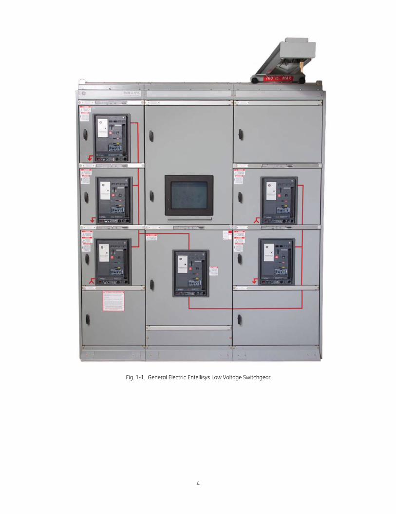
Fig. 1-1. General Electric Entellisys Low Voltage Switchgear
Entellisys Low Voltage Switchgear
5
2. Receiving, Handling, and Storage
2-1 Receiving Equipment Packages
Every package leaving the factory is plainly marked with the case number, requisition number, and customer's order number. If the equipment has been split for shipment, the section numbers of the equipment enclosed in each shipping package are identified.
NOTE: To avoid the loss of any parts when unpacking, the contents of each container should be carefully checked against the packing list before discarding the packing material.
NOTE: Le contenu de chaque conteneur devrait être soigneusement vérifié avec la liste d’emballage avant de décharger le matériel empaqueté, ceci dans le but d’éviter la perte de pièces lors du déballage.
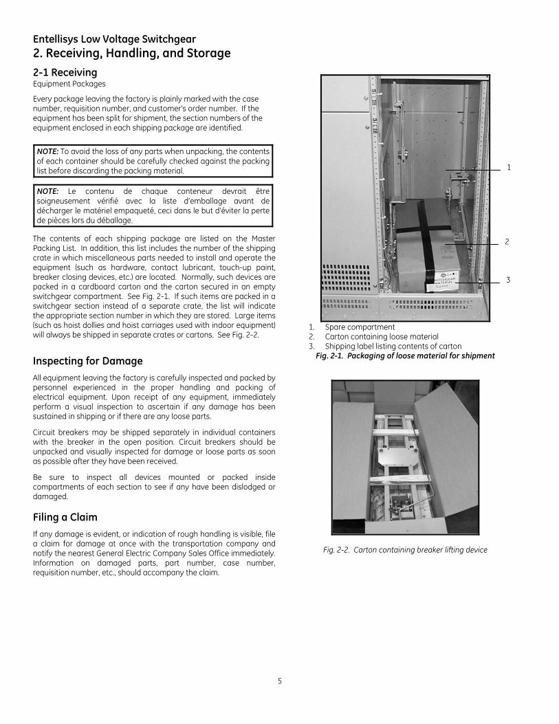
The contents of each shipping package are listed on the Master Packing List. In addition, this list includes the number of the shipping crate in which miscellaneous parts needed to install and operate the equipment (such as hardware, contact lubricant, touch-up paint, breaker closing devices, etc.) are located. Normally, such devices are packed in a cardboard carton and the carton secured in an empty switchgear compartment. See Fig. 2-1. If such items are packed in a switchgear section instead of a separate crate, the list will indicate the appropriate section number in which they are stored. Large items (such as hoist dollies and hoist carriages used with indoor equipment) will always be shipped in separate crates or cartons. See Fig. 2-2.
Inspecting for Damage
All equipment leaving the factory is carefully inspected and packed by personnel experienced in the proper handling and packing of electrical equipment. Upon receipt of any equipment, immediately perform a visual inspection to ascertain if any damage has been sustained in shipping or if there are any loose parts.
Circuit breakers may be shipped separately in individual containers with the breaker in the open position. Circuit breakers should be unpacked and visually inspected for damage or loose parts as soon as possible after they have been received.
Be sure to inspect all devices mounted or packed inside compartments of each section to see if any have been dislodged or damaged. Filing a Claim
If any damage is evident, or indication of rough handling is visible, file a claim for damage at once with the transportation company and notify the nearest General Electric Company Sales Office immediately. Information on damaged parts, part number, case number, requisition number, etc., should accompany the claim.
1. Spare compartment 2. Carton containing loose material 3. Shipping label listing contents of carton
Fig. 2-1. Packaging of loose material for shipment
Fig. 2-2. Carton containing breaker lifting device
3
2
1
6
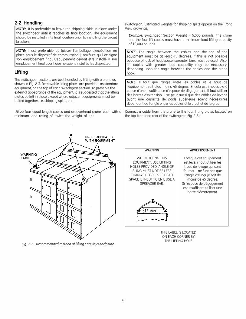
2-2 Handling NOTE: It is preferable to leave the shipping skids in place under the switchgear until it reaches its final location. The equipment should be installed in its final location prior to installing the circuit breakers.
NOTE: Il est préférable de laisser l’emballage d’expédition en place sous le dispositif de commutation jusqu’à ce qu’il atteigne son emplacement final. L’équipement devrait être installé à son emplacement final avant que ne soient installés les disjoncteur.
Lifting
The switchgear sections are best handled by lifting with a crane as shown in Fig. 2-3. Removable lifting plates are provided, as standard equipment, on the top of each switchgear section. To preserve the external appearance of the equipment, it is suggested that the lifting plates be left in place except where adjacent equipments must be bolted together, i.e. shipping splits, etc.
Utilize four equal length cables and an overhead crane, each with a minimum load rating of twice the weight of the
switchgear. Estimated weights for shipping splits appear on the Front View drawings.
Example: Switchgear Section Weight = 5,000 pounds. The crane and the four lift cables must have a minimum load lifting capacity of 10,000 pounds.
NOTE: The angle between the cables and the top of the equipment must be at least 45 degrees. If this is not possible because of lack of headspace, spreader bars must be used. Also, lift cables with greater load capability may be necessary, depending upon the angle between the cables and the crane hook.
NOTE: Il faut que l’angle entre les câbles et le haut de l’équipement soit d’au moins 45 degrés. Si cela est impossible à cause d’une insuffisance d’espace de dégagement, il faut utiliser des barres d’extension. Il se peut aussi que des câbles de levage ayant une capacité de poids supérieure soient nécessaires dépendant de l’angle entre les câbles et le crochet de la grue.
Connect a cable from the crane to the four lifting plates located on the top-front and rear of the switchgear (Fig. 2-3).
Fig. 2 -3. Recommended method of lifting Entellisys enclosure
WARNING ADVERTISSEMENT
WHEN LIFTING THIS EQUIPMENT, USE LIFTING
HOLES PROVIDED. ANGLE OF SLING MUST NOT BE LESS
THAN 45 DEGREES. IF HEAD SPACE IS INSUFFICIENT, USE A
SPREADER BAR.
Lorsque cet équipement est levé, il faut utiliser les trous de levage qui sont
fournis. Il ne fuat pas que l’angle d’élinguje soit de
moins de 45 degrés. Si l’espace de dégagement est insuffisant utiliser une
barre d’écartement.
THIS LABEL IS LOCATED ON EACH CORNER BY
THE LIFTING HOLE
Entellisys Low Voltage Switchgear
7
Take up the slack in the lifting device very carefully and manually stabilize the switchgear to prevent it from rotating.
WARNING: Do not stand under switchgear while it is being moved. Serious injury may occur if the cables or lifting device fail.
AVERTISSEMENT: Ne vous tenez pas sous le dispositif de commutation lorsqu’il est bougé. Des blessures graves peuvent survenir si les câbles ou l’appareil de levage tombent en panne.
CAUTION: Gently lower the switchgear section onto the level site location. If the switchgear is roughly handled or jarred, it is possible to damage or misalign internal components.
ATTENTION: Abaisser doucement la section du dispositif de commutation sur l’endroit d’installation nivelé. Une détérioration ou un désenlignement des composantes internes sont possibles si le dispositif de commutation est manipulé grossièrement ou soumis à des vibrations.
Rollers
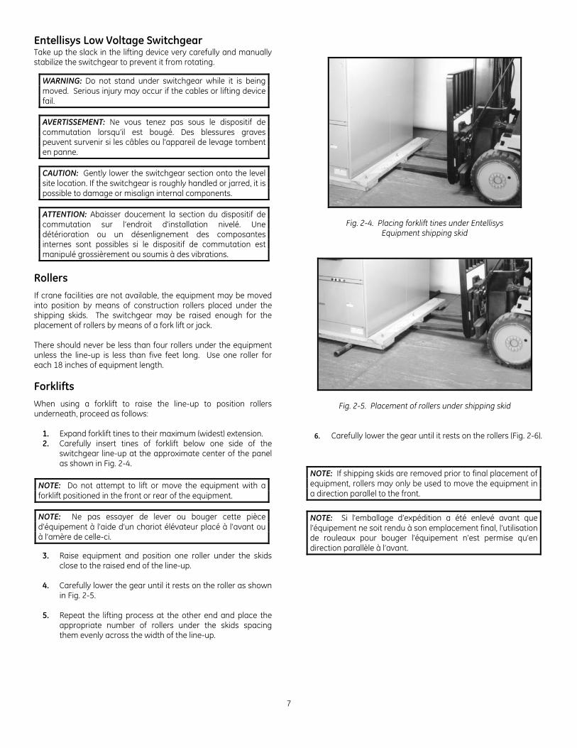
If crane facilities are not available, the equipment may be moved into position by means of construction rollers placed under the shipping skids. The switchgear may be raised enough for the placement of rollers by means of a fork lift or jack. There should never be less than four rollers under the equipment unless the line-up is less than five feet long. Use one roller for each 18 inches of equipment length. Forklifts
When using a forklift to raise the line-up to position rollers underneath, proceed as follows:
1. Expand forklift tines to their maximum (widest) extension. 2. Carefully insert tines of forklift below one side of the
switchgear line-up at the approximate center of the panel as shown in Fig. 2-4.
NOTE: Do not attempt to lift or move the equipment with a forklift positioned in the front or rear of the equipment.
NOTE: Ne pas essayer de lever ou bouger cette pièce d’équipement à l’aide d’un chariot élévateur placé à l’avant ou à l’amère de celle-ci.
3. Raise equipment and position one roller under the skids close to the raised end of the line-up.
4. Carefully lower the gear until it rests on the roller as shown
in Fig. 2-5. 5. Repeat the lifting process at the other end and place the
appropriate number of rollers under the skids spacing them evenly across the width of the line-up.
Fig. 2-4. Placing forklift tines under Entellisys Equipment shipping skid
Fig. 2-5. Placement of rollers under shipping skid
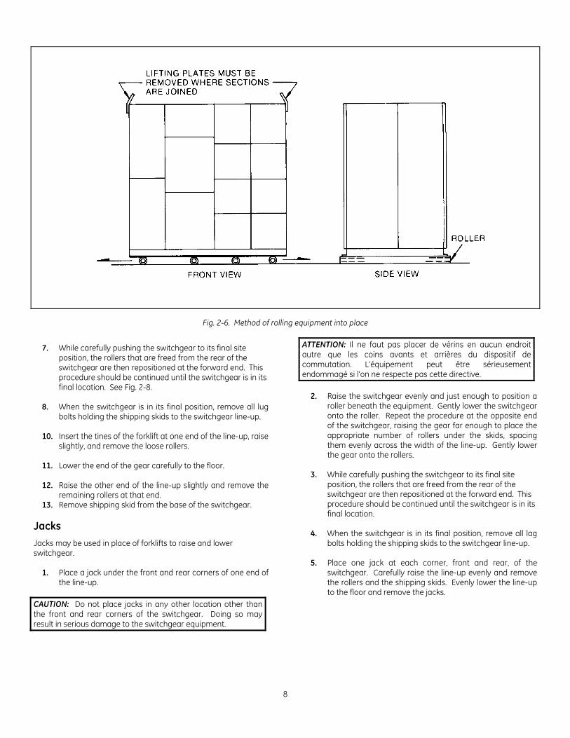
6. Carefully lower the gear until it rests on the rollers (Fig. 2-6).
NOTE: If shipping skids are removed prior to final placement of equipment, rollers may only be used to move the equipment in a direction parallel to the front.
NOTE: Si l’emballage d’expédition a été enlevé avant que l’équipement ne soit rendu à son emplacement final, l’utilisation de rouleaux pour bouger l’équipement n’est permise qu’en direction parallèle à l’avant.
8
Fig. 2-6. Method of rolling equipment into place
7. While carefully pushing the switchgear to its final site position, the rollers that are freed from the rear of the switchgear are then repositioned at the forward end. This procedure should be continued until the switchgear is in its final location. See Fig. 2-8.
8. When the switchgear is in its final position, remove all lug
bolts holding the shipping skids to the switchgear line-up. 10. Insert the tines of the forklift at one end of the line-up, raise
slightly, and remove the loose rollers. 11. Lower the end of the gear carefully to the floor. 12. Raise the other end of the line-up slightly and remove the
remaining rollers at that end. 13. Remove shipping skid from the base of the switchgear.
Jacks
Jacks may be used in place of forklifts to raise and lower switchgear.
1. Place a jack under the front and rear corners of one end of the line-up.
CAUTION: Do not place jacks in any other location other than the front and rear corners of the switchgear. Doing so may result in serious damage to the switchgear equipment.
ATTENTION: Il ne faut pas placer de vérins en aucun endroit autre que les coins avants et arrières du dispositif de commutation. L’équipement peut être sérieusement endommagé si l’on ne respecte pas cette directive.
2. Raise the switchgear evenly and just enough to position a roller beneath the equipment. Gently lower the switchgear onto the roller. Repeat the procedure at the opposite end of the switchgear, raising the gear far enough to place the appropriate number of rollers under the skids, spacing them evenly across the width of the line-up. Gently lower the gear onto the rollers.
3. While carefully pushing the switchgear to its final site
position, the rollers that are freed from the rear of the switchgear are then repositioned at the forward end. This procedure should be continued until the switchgear is in its final location.
4. When the switchgear is in its final position, remove all lag
bolts holding the shipping skids to the switchgear line-up. 5. Place one jack at each corner, front and rear, of the
switchgear. Carefully raise the line-up evenly and remove the rollers and the shipping skids. Evenly lower the line-up to the floor and remove the jacks.
Entellisys Low Voltage Switchgear
9
2-3 Storage Switchgear
If it is necessary to store the switchgear equipment for any length of time, the following precautions should be taken to prevent corrosion or deterioration.
1. Remove protective covering. Check thoroughly for damage. 2. Store in a clean, dry, rodent-free location with moderate
temperature and provide protective coverings to prevent dirt, water, or other foreign substances from entering the switchgear.
CAUTION: Remove all cartons, containers and any other miscellaneous packaging and packing material from inside the switchgear sections before energizing any internal heaters. To prevent fire, remove any plastic or polyethylene shrouding from the switchgear sections before energizing any internal heaters. ATTENTION: Enlever tous les cartons, contenants et tout autre objet varié servant à l’emballage et au matériel d’emballage de l’intérieur des sections du dispositif de commutation avant de procéder à la mise sous tension de tout radiateur interne. Pour éviter un incendie, enlever tout résidu de plastique ou de polyéthylène des sections du dispositif de commutation avant de procéder à la mise sous tension de tous les radiateurs internes.
3. If dampness or condensation may be encountered in the storage location, heaters must be placed inside the switchgear sections to prevent moisture damage. Approximately 250 watts of heat in each section is required. Incandescent lamps may be used for this purpose. These lamps should be located in the
bottom breaker compartment of each section and supported so the bulbs will not touch adjacent materials.
CAUTION: If the space heaters are to be temporarily energized from external source, it is important to remove the fuses on the secondary side of the control power transformer. This precaution is to prevent a feedback of higher voltage to other portions of the equipment through the CPT primary.
ATTENTION: Il est important de retirer les fusibles du côté secondaire du contrôle du pouvoir du transformateur si les espaces des radiateurs doivent être temporairement mis sous tension par une source externe. Cette précaution prévient une rétroaction d’un voltage supérieur à d’autres portions de l’équipement par le contrôle de pouvoir du transformateur primaire.
Circuit Breakers If circuit breakers are not to be placed into service at once, remove them from their shipping cartons and thoroughly inspect them for damage. If the breakers are in satisfactory condition, replace the breakers in their shipping cartons for storage. Do not remove the circuit breaker shipping members at this time. Store the circuit breakers in a clean, dry location in an upright position. They must be properly supported to prevent bending of the studs or damage to any of the breaker parts. Do not remove any protective grease until the circuit breakers are ready to be installed. A plastic or canvas-type cover should be provided to reduce the possibility of damage to the breakers due to dust and water.
10
3. Description
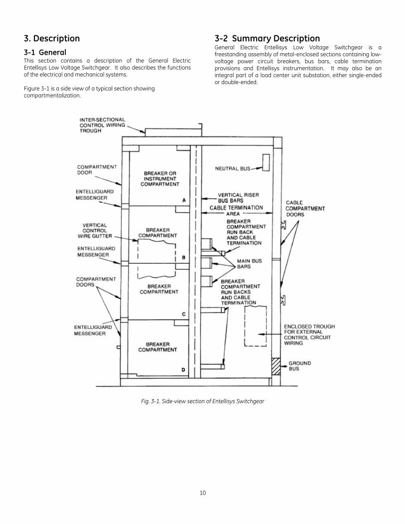
3-1 General This section contains a description of the General Electric Entellisys Low Voltage Switchgear. It also describes the functions of the electrical and mechanical systems. Figure 3-1 is a side view of a typical section showing compartmentalization.
3-2 Summary Description General Electric Entellisys Low Voltage Switchgear is a freestanding assembly of metal-enclosed sections containing low-voltage power circuit breakers, bus bars, cable termination provisions and Entellisys instrumentation. It may also be an integral part of a load center unit substation, either single-ended or double-ended.
Fig. 3-1. Side-view section of Entellisys Switchgear
Entellisys Low Voltage Switchgear
11
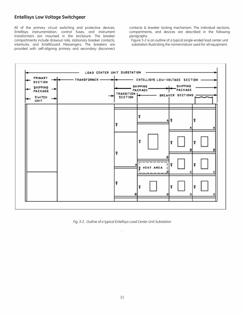
All of the primary circuit switching and protective devices, Entellisys instrumentation, control fuses, and instrument transformers are mounted in the enclosure. The breaker compartments include drawout rails, stationary breaker contacts, interlocks, and EntelliGuard Messengers. The breakers are provided with self-aligning primary and secondary disconnect
contacts & breaker locking mechanism. The individual sections, compartments, and devices are described in the following paragraphs.
Figure 3-2 is an outline of a typical single-ended load center unit substation illustrating the nomenclature used for all equipment.
Fig. 3-2. Outline of a typical Entellisys Load Center Unit Substation
.
12
3-3 Front Compartment Area The front enclosure of each section is divided into individual compartments. These compartments typically house EntelliGuard E low-voltage power circuit breakers or Entellisys instrumentation.
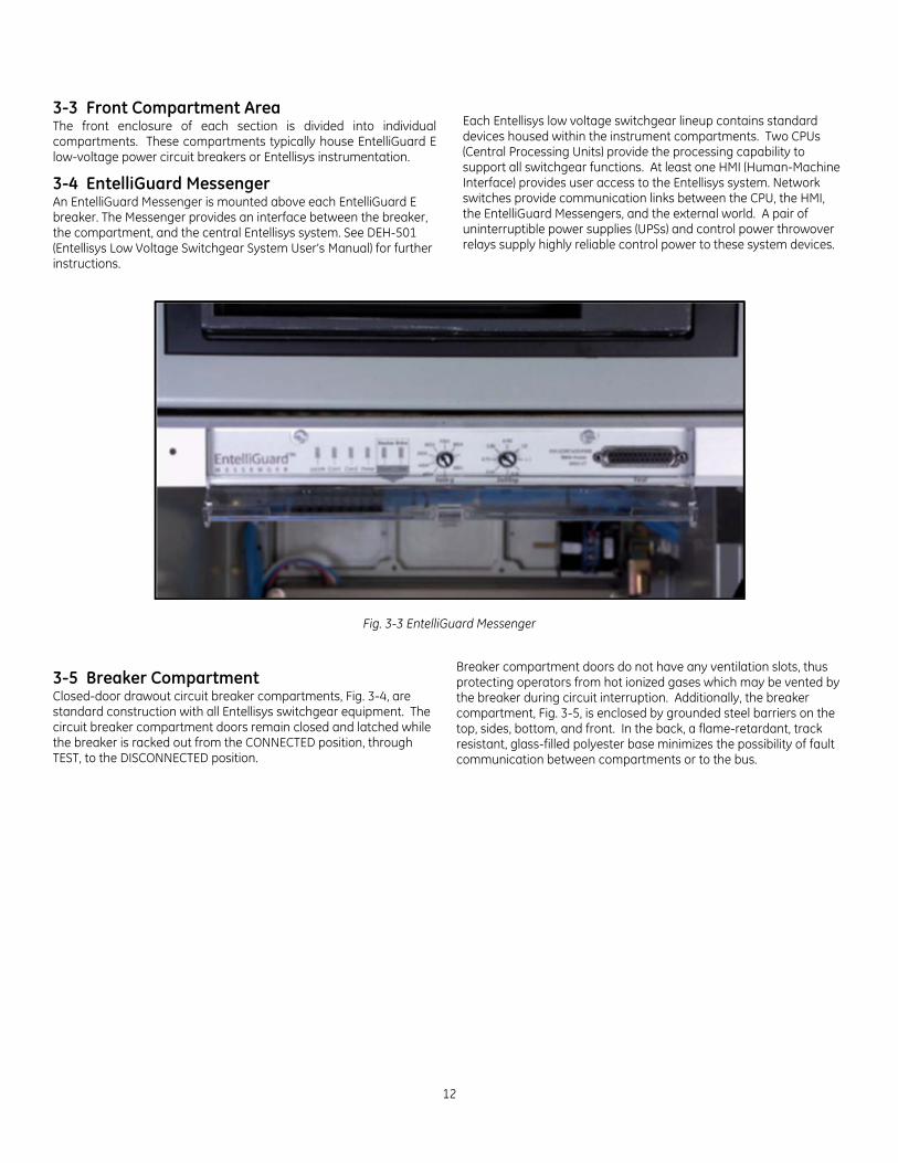
3-4 EntelliGuard Messenger An EntelliGuard Messenger is mounted above each EntelliGuard E breaker. The Messenger provides an interface between the breaker, the compartment, and the central Entellisys system. See DEH-501 (Entellisys Low Voltage Switchgear System User’s Manual) for further instructions.
Each Entellisys low voltage switchgear lineup contains standard devices housed within the instrument compartments. Two CPUs (Central Processing Units) provide the processing capability to support all switchgear functions. At least one HMI (Human-Machine Interface) provides user access to the Entellisys system. Network switches provide communication links between the CPU, the HMI, the EntelliGuard Messengers, and the external world. A pair of uninterruptible power supplies (UPSs) and control power throwover relays supply highly reliable control power to these system devices.
Fig. 3-3 EntelliGuard Messenger
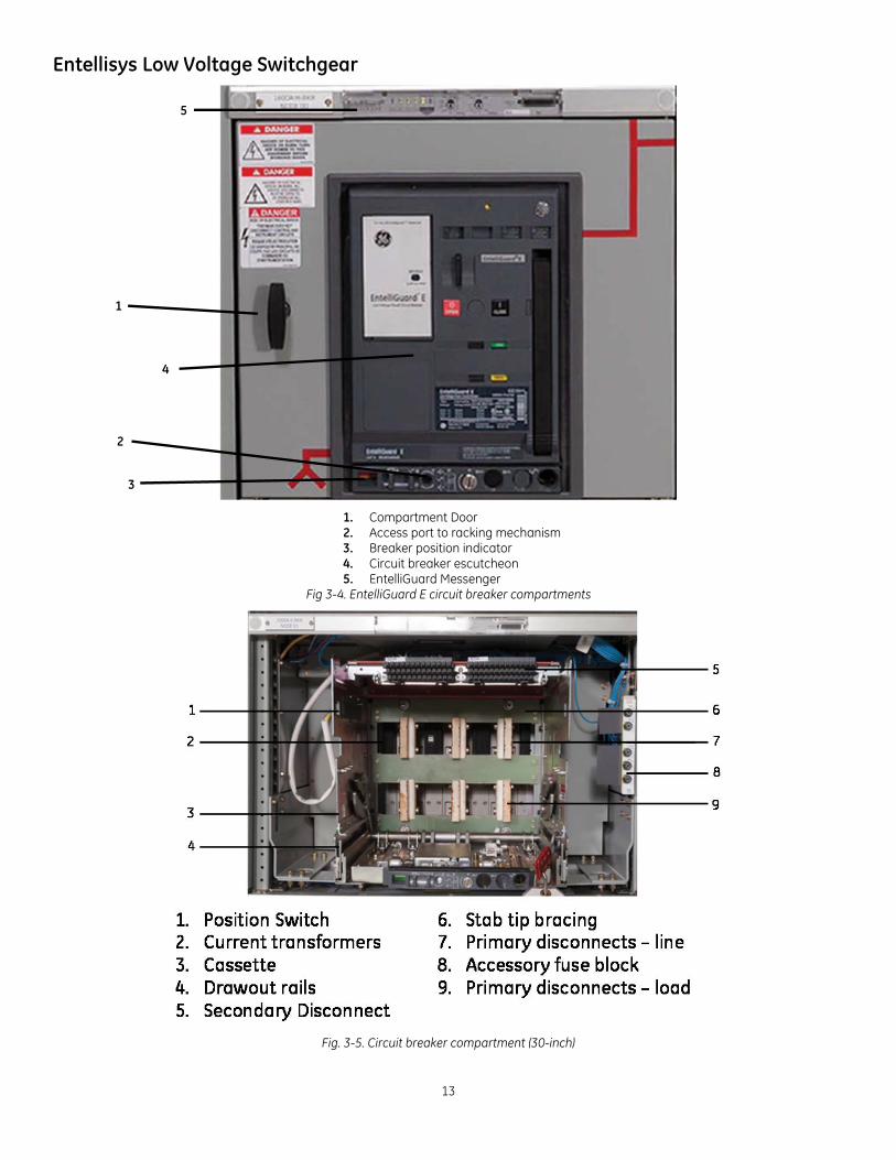
3-5 Breaker Compartment Closed-door drawout circuit breaker compartments, Fig. 3-4, are standard construction with all Entellisys switchgear equipment. The circuit breaker compartment doors remain closed and latched while the breaker is racked out from the CONNECTED position, through TEST, to the DISCONNECTED position.
Breaker compartment doors do not have any ventilation slots, thus protecting operators from hot ionized gases which may be vented by the breaker during circuit interruption. Additionally, the breaker compartment, Fig. 3-5, is enclosed by grounded steel barriers on the top, sides, bottom, and front. In the back, a flame-retardant, track resistant, glass-filled polyester base minimizes the possibility of fault communication between compartments or to the bus.
Entellisys Low Voltage Switchgear
13
1. Compartment Door 2. Access port to racking mechanism 3. Breaker position indicator 4. Circuit breaker escutcheon 5. EntelliGuard Messenger
Fig 3-4. EntelliGuard E circuit breaker compartments
Fig. 3-5. Circuit breaker compartment (30-inch)
5
4
3
2
1
14
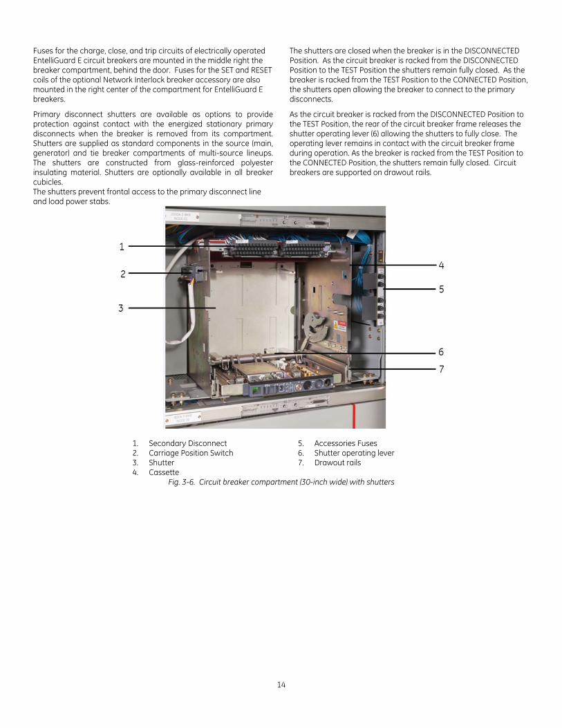
Fuses for the charge, close, and trip circuits of electrically operated EntelliGuard E circuit breakers are mounted in the middle right the breaker compartment, behind the door. Fuses for the SET and RESET coils of the optional Network Interlock breaker accessory are also mounted in the right center of the compartment for EntelliGuard E breakers.
Primary disconnect shutters are available as options to provide protection against contact with the energized stationary primary disconnects when the breaker is removed from its compartment. Shutters are supplied as standard components in the source (main, generator) and tie breaker compartments of multi-source lineups. The shutters are constructed from glass-reinforced polyester insulating material. Shutters are optionally available in all breaker cubicles. The shutters prevent frontal access to the primary disconnect line and load power stabs.
The shutters are closed when the breaker is in the DISCONNECTED Position. As the circuit breaker is racked from the DISCONNECTED Position to the TEST Position the shutters remain fully closed. As the breaker is racked from the TEST Position to the CONNECTED Position, the shutters open allowing the breaker to connect to the primary disconnects.
As the circuit breaker is racked from the DISCONNECTED Position to the TEST Position, the rear of the circuit breaker frame releases the shutter operating lever (6) allowing the shutters to fully close. The operating lever remains in contact with the circuit breaker frame during operation. As the breaker is racked from the TEST Position to the CONNECTED Position, the shutters remain fully closed. Circuit breakers are supported on drawout rails.
1. Secondary Disconnect 5. Accessories Fuses 2. Carriage Position Switch 6. Shutter operating lever 3. Shutter 7. Drawout rails 4. Cassette
Fig. 3-6. Circuit breaker compartment (30-inch wide) with shutters

Entellisys Low Voltage Switchgear
15
Figure 3-7 also shows the shutter assembly with the shutters manually retracted to show the location of the primary disconnect stabs behind the shutter assembly.
1. Stationary barrier 2. Moving barrier 3. Operating lever 4. Secondary disconnects 5. Primary disconnect stabs
Fig. 3-7. Entellisys primary disconnect shutter assembly (Envelope 1 cassette). Shutters manually retracted.
Fig. 3-8. EntelliGuard E circuit breaker
The cassette racking arm slots engage fixed racking anchor pins on the sides of the breaker. As the racking arms are rotated by operation of the racking crank, the breaker is pulled into the compartment, and locked in its final connected position. The breaker should always be OPEN when it is moved into or out of the CONNECTED position. As a safeguard, a draw out interlock will cause the breaker to open before the breaker is able to be moved. All EntelliGuard E circuit breakers of the same type and rating may be interchanged.
Each breaker compartment has four positions as described in the following chart:
Breaker Position in the Cassette
Primary Disconnects
Secondary Disconnects Circuit Breaker Functionality
Circuit Breaker Door Position
CONNECTED Engaged Engaged Circuit Breaker can be operated mechanically or
electrically. Breaker ready for Service
Closed
TEST Disengaged Engaged Circuit Breaker can be operated mechanically or
electrically. Breaker and Control circuits operations can be
tested and verified
Closed
DISCONNECTED Disengaged Disengaged Circuit Breaker can be operated only mechanically Breaker cannot be removed from the circuit
breaker compartment Closed
WITHDARWN Disengaged Disengaged Circuit Breaker can be operated only mechanically Breaker can be removed from the circuit breaker
compartment Open
Table 3-1. Description of the breaker positions.
2
1
3
4
5
16
1. Primary disconnects
Fig. 3-9. Envelope 2 EntelliGuard E circuit breaker (rear view)
1. Racking handle 2. Breaker position indicator
Fig. 3-10. Racking handle for movement of EntelliGuard E
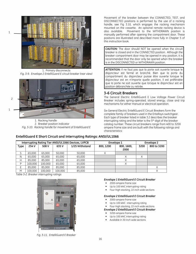
Movement of the breaker between the CONNECTED, TEST, and DISCONNECTED positions is performed by the use of a racking handle, see Fig 3.10, which engages the racking mechanism mounted on the cassette. An optional remote racking device is also available. Movement to the WITHDRAWN position is manually performed after opening the compartment door. These positions are illustrated and described more fully in Chapter 5 of this instruction book.
CAUTION: The door should NOT be opened when the circuit breaker is closed and in the CONNECTED position. Although the breaker compartment door may be opened in any position, it is recommended that the door only be opened when the breaker is in the DISCONNECTED or WITHDRAWN position.
ATTENTION: Il ne faut pas que la porte soit ouverte lorsque le disjoncteur est fermé et branché. Bien que la porte du compartiment du disjoncteur puisse être ouverte lorsque le disjoncteur est en n’importe quelle position, il est préférable que la porte ne soit ouverte que lorsque le disjoncteur est en position débranchée ou retirée.
3-6 Circuit Breakers The General Electric EntelliGuard E Low Voltage Power Circuit Breaker includes spring-operated, stored energy, close and trip mechanisms for either manual or electrical operation. Six General Electric EntelliGuard E Circuit Breakers form the complete family of breakers used in the Entellisys switchgear. Each type of breaker listed in table 3.2 describes the breaker interrupting rating and the letter is the 5th digit of the breaker catalog number. These circuit breakers range from 400 to 3200 ampere frame size and are built with the following ratings and characteristics:
EntelliGuard E Short Circuit and Interrupting Ratings: ANSI/UL1066
Interrupting Rating Tier ANSI/UL1066 Devices, LVPCB Envelope 1 Envelope 2 Type 254 V 508 V 635 V 1/2S Withstand 800, 1200 800, 1600,
2000 3200 800 to 3200
S 65,000 65,000 50,000 50,000 X N 65,000 65,000 65,000 65,000 X X H 85,000 85,000 65,000 65,000 X P 100,000 100,000 65,000 65,000 X E 85,000 85,000 85,000 85,000 X M 100,000 100,000 100,000 85,000 X
Table 3-2. Breaker interrupting ratings
Fig. 3-11. EntelliGuard E Breaker
Envelope 1 EntelliGuard E Circuit Breaker • 2000-ampere frame size • Up to 100 kAIC interrupting rating • Four-high stacking, 22-inch wide sections
Envelope 2 EntelliGuard E Circuit Breaker
• 2000-ampere frame size • Up to 100 kAIC interrupting rating • Four-high stacking, 22-inch wide sections
Envelope 2 EntelliGuard E Circuit Breaker • 3200-ampere frame size • Up to 100 kAIC interrupting rating • Available in 30 inch wide sections
2
1
1
Entellisys Low Voltage Switchgear
17
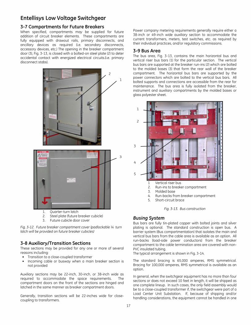
3-7 Compartments for Future Breakers When specified, compartments may be supplied for future addition of circuit breaker elements. These compartments are fully equipped with drawout rails, primary disconnects, and ancillary devices as required (i.e. secondary disconnects, accessory devices, etc.) The opening in the breaker compartment door (3), Fig. 3-13, is closed with a bolted-on steel plate (2) to deter accidental contact with energized electrical circuits.(i.e. primary disconnect stabs).
1. Quarter-turn latch 2. Steel plate (future breaker cubicle) 3. Future cubicle door cover
Fig. 3-12. Future breaker compartment cover (padlockable ¼ turn latch will be provided on future breaker cubicles)
3-8 Auxiliary/Transition Sections These sections may be provided for any one or more of several reasons including:
• Transition to a close-coupled transformer • Incoming cable or busway when a main breaker section is
not provided
Auxiliary sections may be 22-inch, 30-inch, or 38-inch wide as required to accommodate the space requirements. The compartment doors on the front of the sections are hinged and latched in the same manner as breaker compartment doors. Generally, transition sections will be 22-inches wide for close-coupling to transformers.
Power company metering requirements generally require either a 38-inch or 49-inch wide auxiliary section to accommodate the current transformers, meters, test switches, etc. as required by their individual practices, and/or regulatory commissions.
3-9 Bus Area The bus area, Fig. 3-13, contains the main horizontal bus and vertical riser bus bars (1) for the particular section. The vertical bus bars are supported at the breaker run-ins (2) which are bolted to the molded bases (3) that form the rear wall of the breaker compartment. The horizontal bus bars are supported by the power connectors which are bolted to the vertical bus bars. All bolted supports and connections are accessible from the rear for maintenance. The bus area is fully isolated from the breaker, instrument and auxiliary compartments by the molded bases or glass polyester sheet.
1 Vertical riser bus 2. Run-ins to breaker compartment 3. Molded base 4. Run-backs from breaker compartment 5. Short-circuit brace
Fig. 3-13. Bus construction Busing System Bus bars are fully tin-plated copper with bolted joints and silver plating is optional. The standard construction is open bus. A barrier system (Bus compartmentation) that isolates the main and vertical bus bars from the cable area is available as an option. All run-backs (load-side power conductors) from the breaker compartment to the cable termination area are covered with non-PVC insulated tubing. The typical arrangement is shown in Fig. 3-14.
The standard bracing is 65,000 amperes, RMS symmetrical. Bracing for 100,000 amperes, RMS symmetrical is available as an option.
In general, when the switchgear equipment has no more than four sections or does not exceed 10 feet in length, it will be shipped as one complete lineup. In such cases, the only field assembly would be to a close-coupled transformer if, the switchgear were part of a Load Center Unit Substation. If, because of shipping and/or handling considerations, the equipment cannot be handled in one
3
1
2
1
3
4
2
5
18
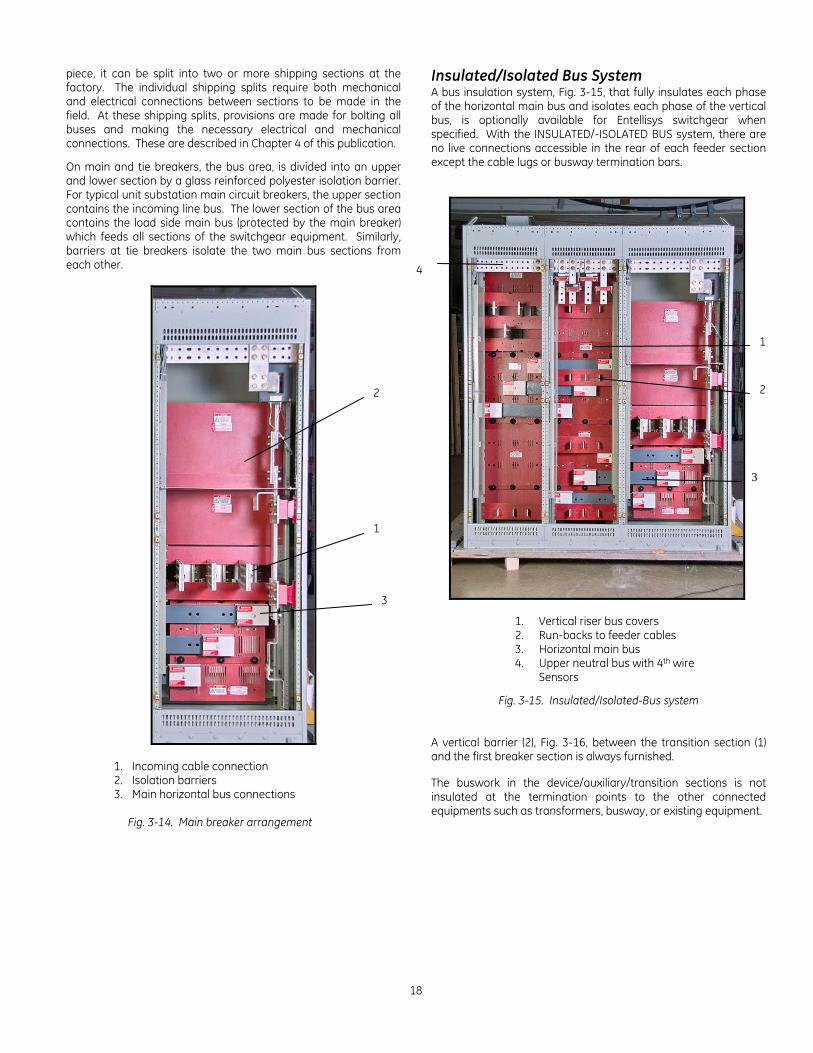
piece, it can be split into two or more shipping sections at the factory. The individual shipping splits require both mechanical and electrical connections between sections to be made in the field. At these shipping splits, provisions are made for bolting all buses and making the necessary electrical and mechanical connections. These are described in Chapter 4 of this publication.
On main and tie breakers, the bus area, is divided into an upper and lower section by a glass reinforced polyester isolation barrier. For typical unit substation main circuit breakers, the upper section contains the incoming line bus. The lower section of the bus area contains the load side main bus (protected by the main breaker) which feeds all sections of the switchgear equipment. Similarly, barriers at tie breakers isolate the two main bus sections from each other.
1. Incoming cable connection 2. Isolation barriers 3. Main horizontal bus connections Fig. 3-14. Main breaker arrangement
Insulated/Isolated Bus System A bus insulation system, Fig. 3-15, that fully insulates each phase of the horizontal main bus and isolates each phase of the vertical bus, is optionally available for Entellisys switchgear when specified. With the INSULATED/-ISOLATED BUS system, there are no live connections accessible in the rear of each feeder section except the cable lugs or busway termination bars.
1. Vertical riser bus covers 2. Run-backs to feeder cables 3. Horizontal main bus 4. Upper neutral bus with 4th wire Sensors
Fig. 3-15. Insulated/Isolated-Bus system
A vertical barrier (2), Fig. 3-16, between the transition section (1) and the first breaker section is always furnished. The buswork in the device/auxiliary/transition sections is not insulated at the termination points to the other connected equipments such as transformers, busway, or existing equipment.
1
2
3
4
1
2
3
Entellisys Low Voltage Switchgear
19
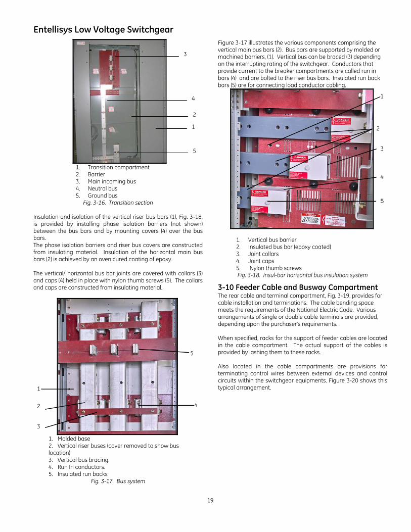
1. Transition compartment 2. Barrier 3. Main incoming bus 4. Neutral bus 5. Ground bus
Fig. 3-16. Transition section Insulation and isolation of the vertical riser bus bars (1), Fig. 3-18, is provided by installing phase isolation barriers (not shown) between the bus bars and by mounting covers (4) over the bus bars. The phase isolation barriers and riser bus covers are constructed from insulating material. Insulation of the horizontal main bus bars (2) is achieved by an oven cured coating of epoxy. The vertical/ horizontal bus bar joints are covered with collars (3) and caps (4) held in place with nylon thumb screws (5). The collars and caps are constructed from insulating material.
1. Molded base 2. Vertical riser buses (cover removed to show bus location) 3. Vertical bus bracing. 4. Run In conductors. 5. Insulated run backs
Fig. 3-17. Bus system
Figure 3-17 illustrates the various components comprising the vertical main bus bars (2). Bus bars are supported by molded or machined barriers, (1). Vertical bus can be braced (3) depending on the interrupting rating of the switchgear. Conductors that provide current to the breaker compartments are called run in bars (4) and are bolted to the riser bus bars. Insulated run back bars (5) are for connecting load conductor cabling.
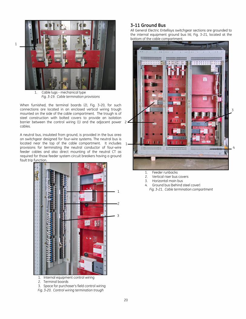
1. Vertical bus barrier 2. Insulated bus bar (epoxy coated) 3. Joint collars
4. Joint caps 5. Nylon thumb screws Fig. 3-18. Insul-bar horizontal bus insulation system
3-10 Feeder Cable and Busway Compartment The rear cable and terminal compartment, Fig. 3-19, provides for cable installation and terminations. The cable bending space meets the requirements of the National Electric Code. Various arrangements of single or double cable terminals are provided, depending upon the purchaser's requirements. When specified, racks for the support of feeder cables are located in the cable compartment. The actual support of the cables is provided by lashing them to these racks. Also located in the cable compartments are provisions for terminating control wires between external devices and control circuits within the switchgear equipments. Figure 3-20 shows this typical arrangement.
1
3
2
4
5
2
1
5
2
3
4
5
1
4
3
20
1. Cable lugs - mechanical type
Fig. 3-19. Cable termination provisions When furnished, the terminal boards (2), Fig. 3-20, for such connections are located in an enclosed vertical wiring trough mounted on the side of the cable compartment. The trough is of steel construction with bolted covers to provide an isolation barrier between the control wiring (1) and the adjacent power cables. A neutral bus, insulated from ground, is provided in the bus area on switchgear designed for four-wire systems. The neutral bus is located near the top of the cable compartment. It includes provisions for terminating the neutral conductor of four-wire feeder cables and also direct mounting of the neutral CT as required for those feeder system circuit breakers having a ground fault trip function.
1. Internal equipment control wiring 2. Terminal boards 3. Space for purchaser's field control wiring
Fig. 3-20. Control wiring termination trough
3-11 Ground Bus All General Electric Entellisys switchgear sections are grounded to the internal equipment ground bus (4), Fig. 3-21, located at the bottom of the cable compartment.
1. Feeder runbacks 2. Vertical riser bus covers 3. Horizontal main bus 4. Ground bus (behind steel cover)
Fig. 3-21. Cable termination compartment
1
2
3
1
3
4
2
1
Entellisys Low Voltage Switchgear
21
4. Equipment Installation
4-1 General This chapter contains complete instructions for installing General Electric Entellisys Low-voltage Switchgear.
CAUTION: Personnel installing this equipment must be thoroughly familiar with this instruction manual and all articles of the National Electrical Code applicable to the installation of this switchgear. In addition, all drawings, both mechanical installation and electrical, must be understood and strictly followed to prevent damage to the switchgear or equipment being protected by the switchgear.
ATTENTION: La ou les personnes procédant à l’installation de cet équipement doivent être tout à fait familier avec ce livre d’instruction ainsi que tous les articles du Code national d’électricité s’appliquant à l’installation de ce dispositif de commutation. De plus, tous les dessins se rapportant tant à l’installation mécanique qu’électrique doivent être compris et suivis à la lettre afin de prévenir des dommages au dispositif de commutation ou à l’équipement protégé par celui-ci.
NOTE: Before installation work is started, it is important to review all of the drawings provided, including the General Electric equipment arrangement drawings, site installation drawings, elementary and remote connection drawings, mechanical connection drawings, and the summary of equipment list.
NOTE: Il est important de reviser tous les dessins fournis, incluant les dessins de disposition de l’équipement de General Electric, les dessins d’installation du site, les dessins de raccords élémentaires et à distance, les dessins de raccords mécaniques et le sommaire de la liste d’équipement avant que ne débutent les travaux d’installation.
All expendable hardware for shipping purposes only, is painted yellow or tagged with yellow adhesive tape and may be discarded at completion of the installation phase. Site Location In general, the location of the switchgear equipment will have been predetermined during the specification and/or procurement of equipment phases. Indoor locations within buildings impose certain requirements which must be met so that the switchgear may operate efficiently with a minimum of maintenance. In locating the Entellisys Switchgear, adequate aisle space must be provided at the front and rear of the equipment to ensure proper ventilation of the equipment and to allow service and maintenance of the equipment with the front and rear doors open. The recommended aisle space is shown on the floor plan supplied with the equipment drawings. The switchgear equipment should be placed in an area where clean, dry air is free to circulate around and above it. Since air is taken into the equipment at the bottom of each section and exhausted at the top, a location with good airflow must be provided for efficient operation. A minimum of 30 inches of clear space above the equipment is recommended.
Foundation Requirements For optimum performance of your General Electric switchgear equipment, the foundation requirements expressed in this chapter should be strictly adhered to.
NOTE: The foundation for the outdoor switchgear must provide proper drainage of ground and/or surface water accumulations away from the equipment.
NOTE: La fondation du dispositif de commutation situé à l’intérieur doit être en mesure de drainer correctement les accumulations d’eau du sol et de surface loin de l’équipement.
The foundation must be strong enough to prevent sagging due to the weight of the switchgear structure and to withstand the shock stress caused by the opening of the breakers under fault conditions. The shock loading is approximately 1-1/2 times the static load. The foundation must be flat and level in all planes. Refer to Figure 4-1 for definition of flat and level.
Fig. 4-1. Definition of flat and level
Foundation Preparation Indoor Equipment Refer to Fig. 4-2 along with the owner's foundation construction drawings, and the General Electric supplemental installation drawings. Although the indoor switchgear equipment can be mounted directly on a smooth, level floor, it is recommended that recessed steel channels be installed for supporting the equipment. Anchor bolts and channels are to be provided by the purchaser.
22
NOTE: When the equipment is installed on a surface subject to impact (shock) loads due to operating conditions or environmental seismic (earthquake) conditions, the anchor bolts should be fabricated of medium carbon steel (grade 5 load rating).
NOTE: Lorsque l’équipement est installé sur une surface sujette à des charges d’impact (choc) causées par les conditions d’opération ou des séismes environnementaux (tremblements de terre), les boulons d’ancrage devraient être fabriqués d’acier à moyenne teneur en carbone (spécification de charge classe 5).
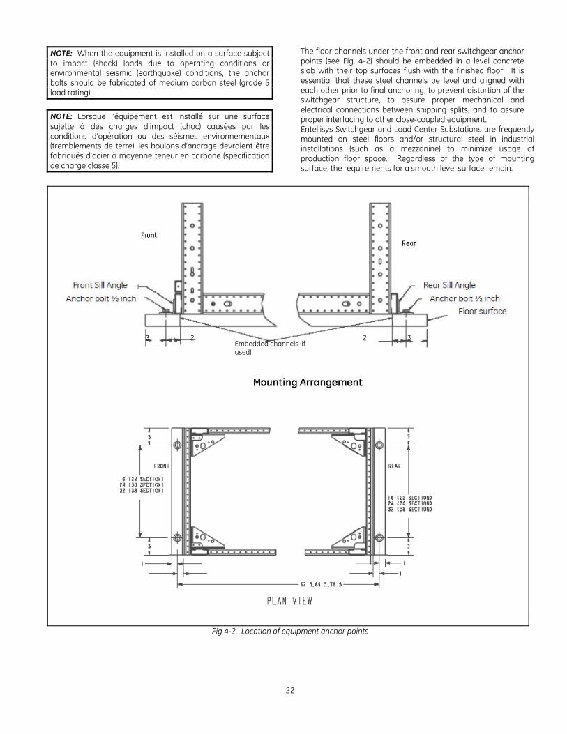
The floor channels under the front and rear switchgear anchor points (see Fig. 4-2) should be embedded in a level concrete slab with their top surfaces flush with the finished floor. It is essential that these steel channels be level and aligned with each other prior to final anchoring, to prevent distortion of the switchgear structure, to assure proper mechanical and electrical connections between shipping splits, and to assure proper interfacing to other close-coupled equipment. Entellisys Switchgear and Load Center Substations are frequently mounted on steel floors and/or structural steel in industrial installations (such as a mezzanine) to minimize usage of production floor space. Regardless of the type of mounting surface, the requirements for a smooth level surface remain.
Fig 4-2. Location of equipment anchor points
Embedded channels (if used)
3 3 2 2
Entellisys Low Voltage Switchgear
23
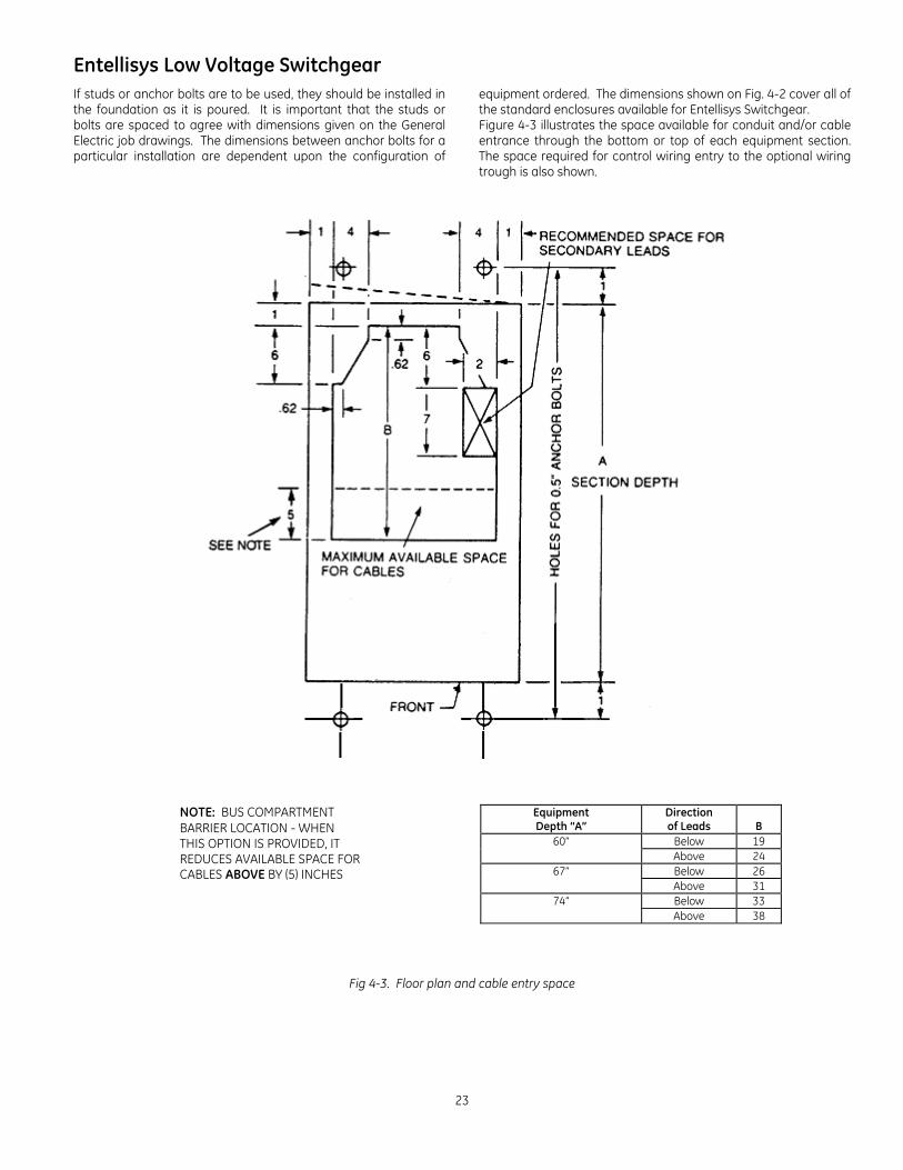
If studs or anchor bolts are to be used, they should be installed in the foundation as it is poured. It is important that the studs or bolts are spaced to agree with dimensions given on the General Electric job drawings. The dimensions between anchor bolts for a particular installation are dependent upon the configuration of
equipment ordered. The dimensions shown on Fig. 4-2 cover all of the standard enclosures available for Entellisys Switchgear. Figure 4-3 illustrates the space available for conduit and/or cable entrance through the bottom or top of each equipment section. The space required for control wiring entry to the optional wiring trough is also shown.
NOTE: BUS COMPARTMENT BARRIER LOCATION - WHEN THIS OPTION IS PROVIDED, IT REDUCES AVAILABLE SPACE FOR CABLES ABOVE BY (5) INCHES
Equipment Depth “A”
Direction of Leads
B
60” Below 19 Above 24
67” Below 26 Above 31
74” Below 33 Above 38
Fig 4-3. Floor plan and cable entry space
24
4-2 Assembly and Installation of Switchgear Equipment General Requirements
Before assembling or installing the switchgear equipment, all components should be available at the site location. This will facilitate switchgear component identification as well as installation. The foundation should be prepared in accordance with the instructions in Sections 4-1 and 4-2, and all embedded conduits installed and capped.
NOTE: If rollers are to be used for movement of the equipment to its permanent installation, it is recommended that the shipping skid not be removed until the equipment is placed in position over the anchor bolts.
NOTE: Au cas où l’utilisation de rouleaux s’avérerait nécessaire afin d’apporter l’équipement à son emplacement permanent, nous recommandons que l’emballage d’expédition ne soit pas enlevé tant que l’équipement n’est pas positionné au dessus des boulons d’ancrage.
If a transformer is not part of the installation, and/or the equipment has been split for shipment, place the center section on the foundation first. Assemble the remaining sections outward from the center section, in each direction.
If the switchgear equipment is part of a Load Center Unit Substation, the transformer section should be set on its pad first in accordance with the instructions furnished with the transformer. All remaining sections of the switchgear should then be installed.
NOTE: Before assembling and installing the switchgear equipment, the foundation must be absolutely level and clear of debris to prevent damage and possible misoperation of the switchgear equipment.
NOTE: Il faut avant de procéder à l’assemblage et à l’installation s’assurer que la fondation soit absolument au niveau et exempte de débris afin de prévenir des dommages à l’équipement du dispositif de commutation.
Detailed Assembly and Installation Instructions The recommended procedure for installation of an indoor switchgear or Load Center Unit Substation is as follows:
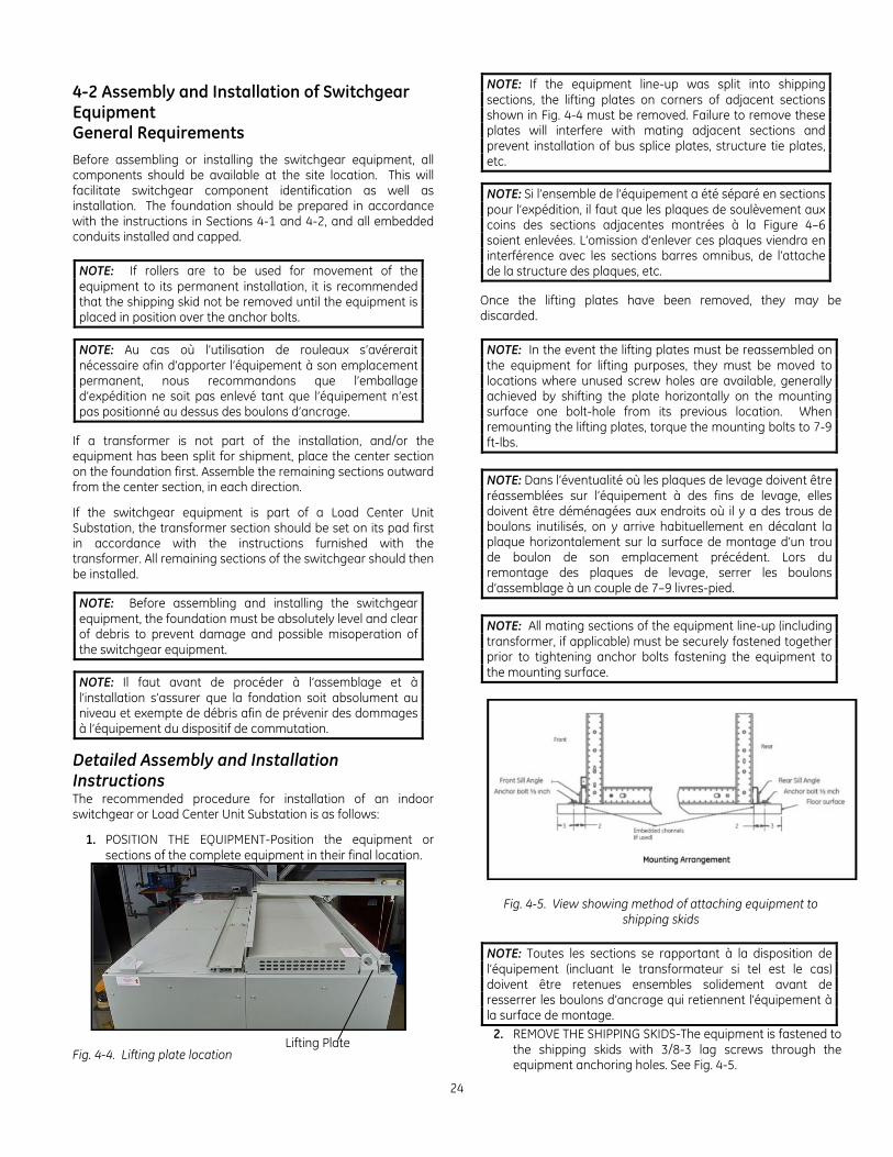
1. POSITION THE EQUIPMENT-Position the equipment or sections of the complete equipment in their final location.
Fig. 4-4. Lifting plate location
NOTE: If the equipment line-up was split into shipping sections, the lifting plates on corners of adjacent sections shown in Fig. 4-4 must be removed. Failure to remove these plates will interfere with mating adjacent sections and prevent installation of bus splice plates, structure tie plates, etc.
NOTE: Si l’ensemble de l’équipement a été séparé en sections pour l’expédition, il faut que les plaques de soulèvement aux coins des sections adjacentes montrées à la Figure 4–6 soient enlevées. L’omission d’enlever ces plaques viendra en interférence avec les sections barres omnibus, de l’attache de la structure des plaques, etc.
Once the lifting plates have been removed, they may be discarded.
NOTE: In the event the lifting plates must be reassembled on the equipment for lifting purposes, they must be moved to locations where unused screw holes are available, generally achieved by shifting the plate horizontally on the mounting surface one bolt-hole from its previous location. When remounting the lifting plates, torque the mounting bolts to 7-9 ft-lbs.
NOTE: Dans l’éventualité où les plaques de levage doivent être réassemblées sur l’équipement à des fins de levage, elles doivent être déménagées aux endroits où il y a des trous de boulons inutilisés, on y arrive habituellement en décalant la plaque horizontalement sur la surface de montage d’un trou de boulon de son emplacement précédent. Lors du remontage des plaques de levage, serrer les boulons d’assemblage à un couple de 7–9 livres-pied.
NOTE: All mating sections of the equipment line-up (including transformer, if applicable) must be securely fastened together prior to tightening anchor bolts fastening the equipment to the mounting surface.
Fig. 4-5. View showing method of attaching equipment to shipping skids
NOTE: Toutes les sections se rapportant à la disposition de l’équipement (incluant le transformateur si tel est le cas) doivent être retenues ensembles solidement avant de resserrer les boulons d’ancrage qui retiennent l’équipement à la surface de montage.
2. REMOVE THE SHIPPING SKIDS-The equipment is fastened to the shipping skids with 3/8-3 lag screws through the equipment anchoring holes. See Fig. 4-5.
Lifting Plate
Entellisys Low Voltage Switchgear
25
Equipment shipping sections up to 10 feet long will be fastened to the skids with four lag screws, one in each corner. The shipping skid and lag screws are expendable material and may be disposed of at the purchaser's discretion.
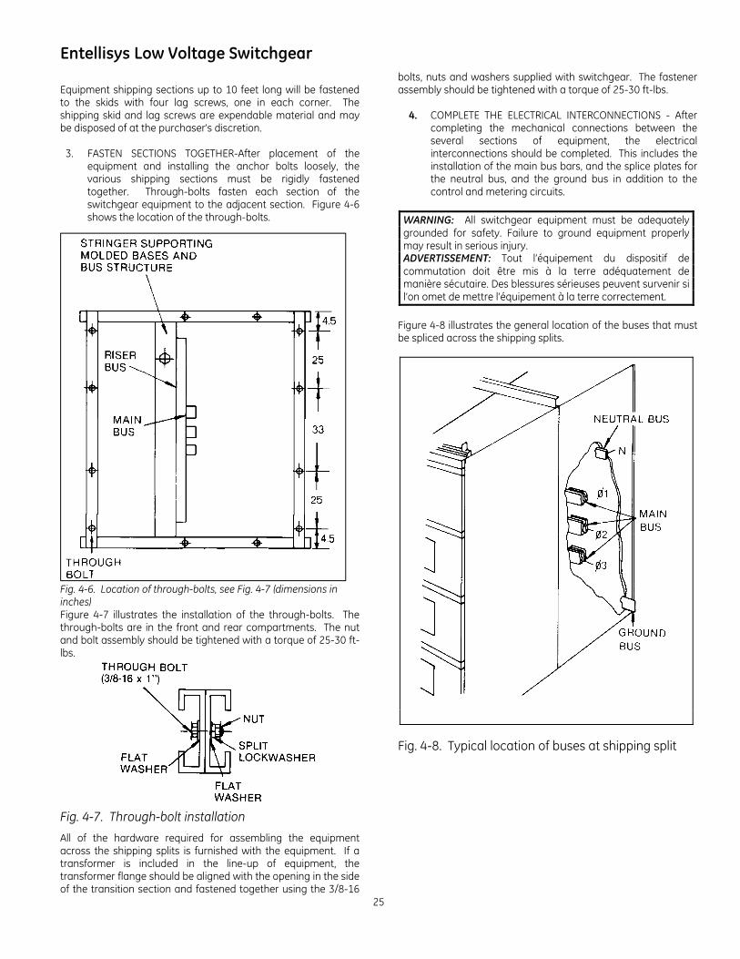
3. FASTEN SECTIONS TOGETHER-After placement of the equipment and installing the anchor bolts loosely, the various shipping sections must be rigidly fastened together. Through-bolts fasten each section of the switchgear equipment to the adjacent section. Figure 4-6 shows the location of the through-bolts.
Fig. 4-6. Location of through-bolts, see Fig. 4-7 (dimensions in inches) Figure 4-7 illustrates the installation of the through-bolts. The through-bolts are in the front and rear compartments. The nut and bolt assembly should be tightened with a torque of 25-30 ft-lbs.
Fig. 4-7. Through-bolt installation
All of the hardware required for assembling the equipment across the shipping splits is furnished with the equipment. If a transformer is included in the line-up of equipment, the transformer flange should be aligned with the opening in the side of the transition section and fastened together using the 3/8-16
bolts, nuts and washers supplied with switchgear. The fastener assembly should be tightened with a torque of 25-30 ft-lbs.
4. COMPLETE THE ELECTRICAL INTERCONNECTIONS - After completing the mechanical connections between the several sections of equipment, the electrical interconnections should be completed. This includes the installation of the main bus bars, and the splice plates for the neutral bus, and the ground bus in addition to the control and metering circuits.
WARNING: All switchgear equipment must be adequately grounded for safety. Failure to ground equipment properly may result in serious injury. ADVERTISSEMENT: Tout l’équipement du dispositif de commutation doit être mis à la terre adéquatement de manière sécutaire. Des blessures sérieuses peuvent survenir si l’on omet de mettre l’équipement à la terre correctement.
Figure 4-8 illustrates the general location of the buses that must be spliced across the shipping splits.
Fig. 4-8. Typical location of buses at shipping split
26
The ground bus is mounted directly on the rear upright channels.
NOTE: It is particularly important that the ground bus be connected first since it provides an integral ground for all the equipment. It must also be connected to the station ground prior to proceeding with the installation.
NOTE: Il est particulièrement important que la barre omnibus de mise à la terre soit branchée en premier, étant donné qu’elle fournit une mise à la terre intégrale à tout l’équipement. Elle doit aussi être branchée à la mise à la terre du poste avant de procéder à la installation.
A 4/0 AWG cable connector is located in the bottom of the transition section (or in the incoming line compartment if a transition section is not included) for terminating the purchaser's cable connection to ground. The specific location of the station ground connection is shown on the site floor plan drawing and on the frontview drawings supplied with the equipment. All grounding of the switchgear should be in accordance with National Electrical Code.
Fig. 4-9. Plan view of ground bus splice installation
Figure 4-9 illustrates the installation of the ground bus splice plate across a shipping split. In addition to the bolted fastening of the splice plate to the two ends of the ground bus, self-tapping 1/4-20 bolts pass through the splice plate and ground bus stubs, and thread into the equipment frame. These bolts should be fastened with a torque of 7-9 ft-lbs.
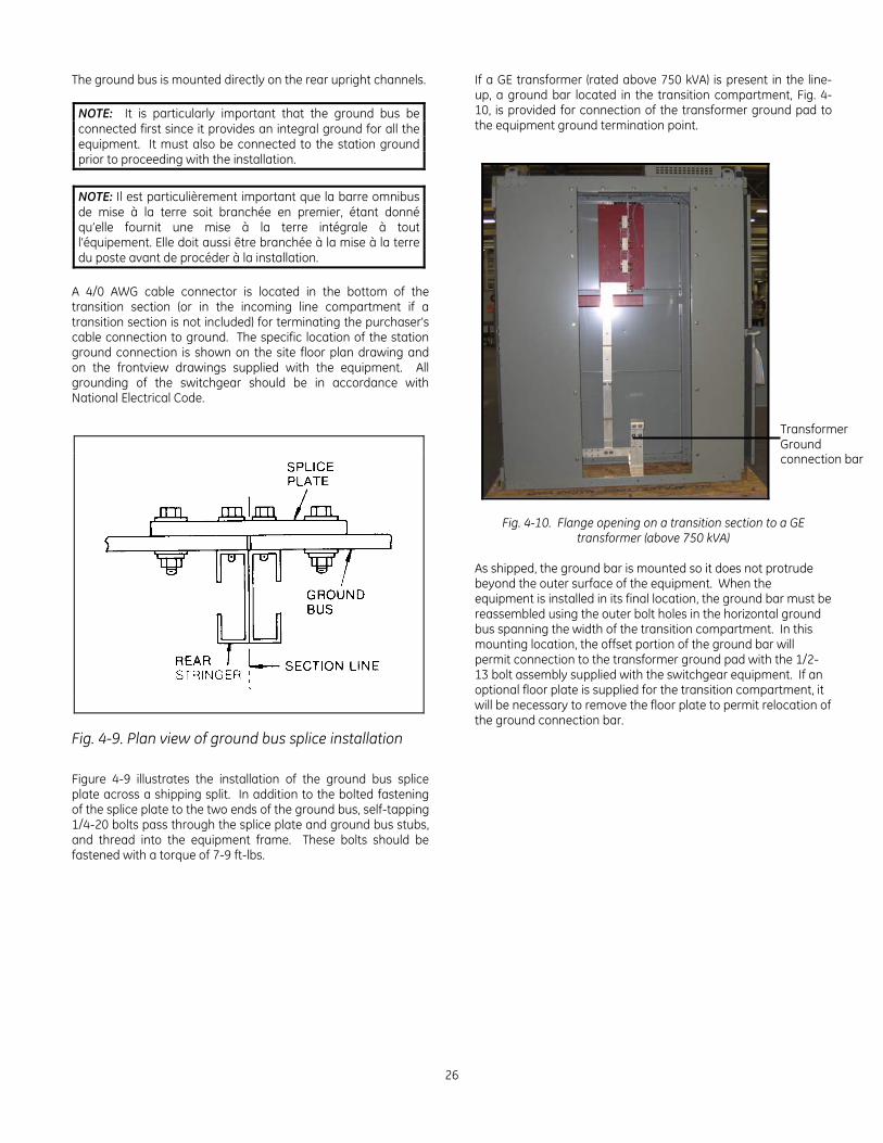
If a GE transformer (rated above 750 kVA) is present in the line-up, a ground bar located in the transition compartment, Fig. 4-10, is provided for connection of the transformer ground pad to the equipment ground termination point.
Fig. 4-10. Flange opening on a transition section to a GE transformer (above 750 kVA)
As shipped, the ground bar is mounted so it does not protrude beyond the outer surface of the equipment. When the equipment is installed in its final location, the ground bar must be reassembled using the outer bolt holes in the horizontal ground bus spanning the width of the transition compartment. In this mounting location, the offset portion of the ground bar will permit connection to the transformer ground pad with the 1/2-13 bolt assembly supplied with the switchgear equipment. If an optional floor plate is supplied for the transition compartment, it will be necessary to remove the floor plate to permit relocation of the ground connection bar.
Transformer Ground connection bar
Entellisys Low Voltage Switchgear
27
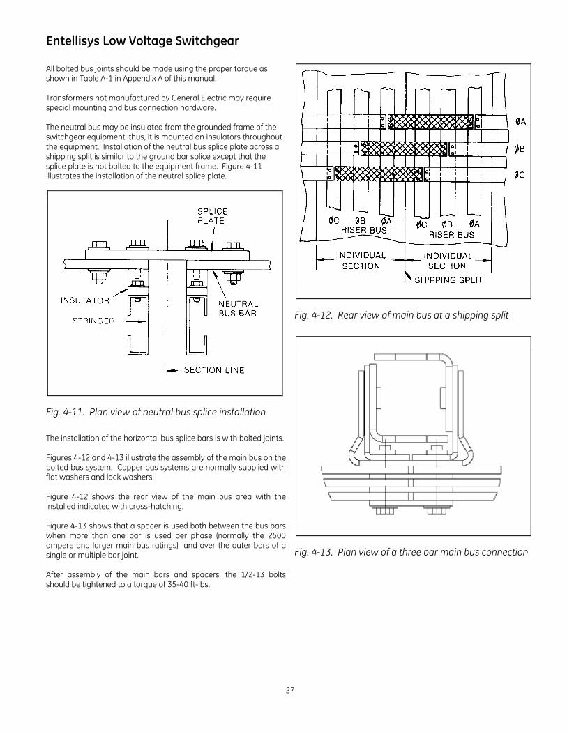
All bolted bus joints should be made using the proper torque as shown in Table A-1 in Appendix A of this manual. Transformers not manufactured by General Electric may require special mounting and bus connection hardware. The neutral bus may be insulated from the grounded frame of the switchgear equipment; thus, it is mounted on insulators throughout the equipment. Installation of the neutral bus splice plate across a shipping split is similar to the ground bar splice except that the splice plate is not bolted to the equipment frame. Figure 4-11 illustrates the installation of the neutral splice plate.
Fig. 4-11. Plan view of neutral bus splice installation
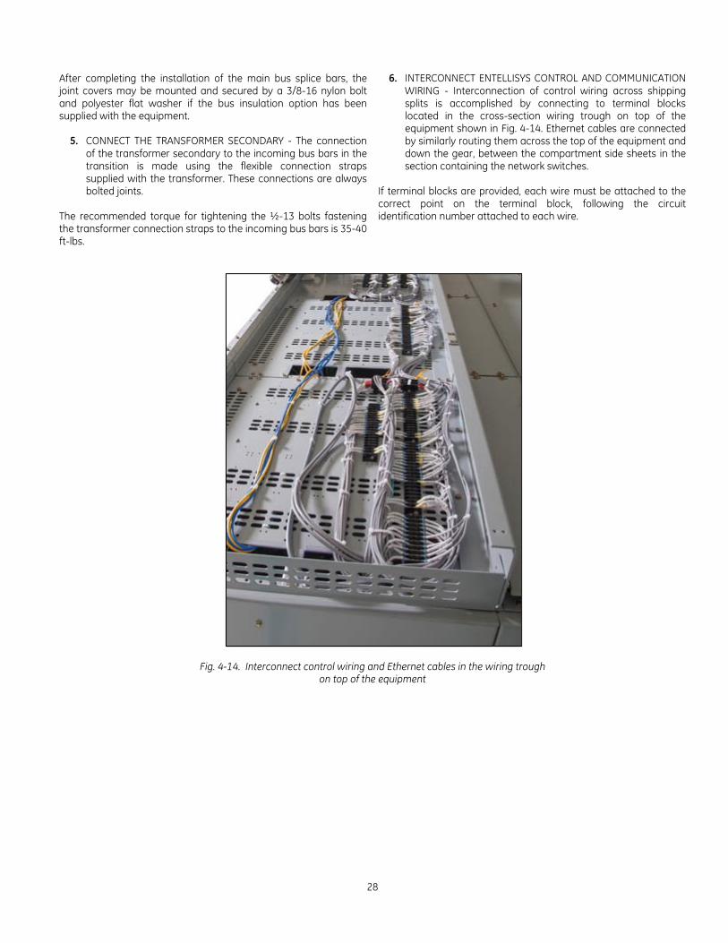
The installation of the horizontal bus splice bars is with bolted joints. Figures 4-12 and 4-13 illustrate the assembly of the main bus on the bolted bus system. Copper bus systems are normally supplied with flat washers and lock washers. Figure 4-12 shows the rear view of the main bus area with the installed indicated with cross-hatching. Figure 4-13 shows that a spacer is used both between the bus bars when more than one bar is used per phase (normally the 2500 ampere and larger main bus ratings) and over the outer bars of a single or multiple bar joint. After assembly of the main bars and spacers, the 1/2-13 bolts should be tightened to a torque of 35-40 ft-lbs.
Fig. 4-12. Rear view of main bus at a shipping split
Fig. 4-13. Plan view of a three bar main bus connection
28
After completing the installation of the main bus splice bars, the joint covers may be mounted and secured by a 3/8-16 nylon bolt and polyester flat washer if the bus insulation option has been supplied with the equipment.
5. CONNECT THE TRANSFORMER SECONDARY - The connection of the transformer secondary to the incoming bus bars in the transition is made using the flexible connection straps supplied with the transformer. These connections are always bolted joints.
The recommended torque for tightening the ½-13 bolts fastening the transformer connection straps to the incoming bus bars is 35-40 ft-lbs.
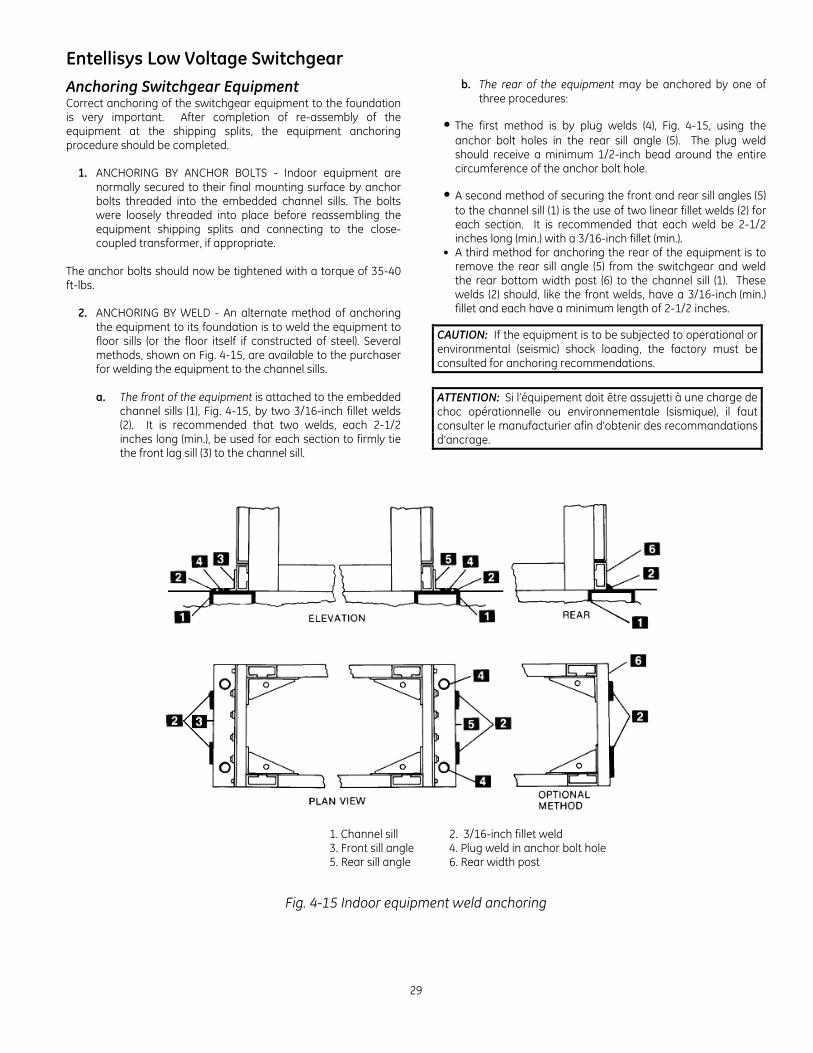
6. INTERCONNECT ENTELLISYS CONTROL AND COMMUNICATION WIRING - Interconnection of control wiring across shipping splits is accomplished by connecting to terminal blocks located in the cross-section wiring trough on top of the equipment shown in Fig. 4-14. Ethernet cables are connected by similarly routing them across the top of the equipment and down the gear, between the compartment side sheets in the section containing the network switches.
If terminal blocks are provided, each wire must be attached to the correct point on the terminal block, following the circuit identification number attached to each wire.
Fig. 4-14. Interconnect control wiring and Ethernet cables in the wiring trough on top of the equipment
Entellisys Low Voltage Switchgear
29
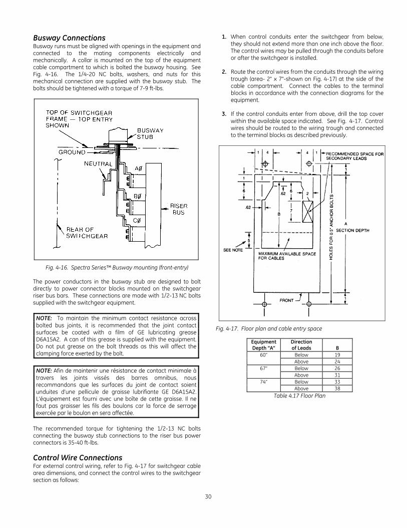
Anchoring Switchgear Equipment Correct anchoring of the switchgear equipment to the foundation is very important. After completion of re-assembly of the equipment at the shipping splits, the equipment anchoring procedure should be completed.
1. ANCHORING BY ANCHOR BOLTS - Indoor equipment are normally secured to their final mounting surface by anchor bolts threaded into the embedded channel sills. The bolts were loosely threaded into place before reassembling the equipment shipping splits and connecting to the close-coupled transformer, if appropriate.
The anchor bolts should now be tightened with a torque of 35-40 ft-lbs.
2. ANCHORING BY WELD - An alternate method of anchoring the equipment to its foundation is to weld the equipment to floor sills (or the floor itself if constructed of steel). Several methods, shown on Fig. 4-15, are available to the purchaser for welding the equipment to the channel sills.
a. The front of the equipment is attached to the embedded
channel sills (1), Fig. 4-15, by two 3/16-inch fillet welds (2). It is recommended that two welds, each 2-1/2 inches long (min.), be used for each section to firmly tie the front lag sill (3) to the channel sill.
b. The rear of the equipment may be anchored by one of three procedures:
• The first method is by plug welds (4), Fig. 4-15, using the anchor bolt holes in the rear sill angle (5). The plug weld should receive a minimum 1/2-inch bead around the entire circumference of the anchor bolt hole.
• A second method of securing the front and rear sill angles (5) to the channel sill (1) is the use of two linear fillet welds (2) for each section. It is recommended that each weld be 2-1/2 inches long (min.) with a 3/16-inch fillet (min.).
• A third method for anchoring the rear of the equipment is to remove the rear sill angle (5) from the switchgear and weld the rear bottom width post (6) to the channel sill (1). These welds (2) should, like the front welds, have a 3/16-inch (min.) fillet and each have a minimum length of 2-1/2 inches.
CAUTION: If the equipment is to be subjected to operational or environmental (seismic) shock loading, the factory must be consulted for anchoring recommendations.
ATTENTION: Si l’équipement doit être assujetti à une charge de choc opérationnelle ou environnementale (sismique), il faut consulter le manufacturier afin d’obtenir des recommandations d’ancrage.
1. Channel sill 2. 3/16-inch fillet weld 3. Front sill angle 4. Plug weld in anchor bolt hole 5. Rear sill angle 6. Rear width post
Fig. 4-15 Indoor equipment weld anchoring
30
Busway Connections Busway runs must be aligned with openings in the equipment and connected to the mating components electrically and mechanically. A collar is mounted on the top of the equipment cable compartment to which is bolted the busway housing. See Fig. 4-16. The 1/4-20 NC bolts, washers, and nuts for this mechanical connection are supplied with the busway stub. The bolts should be tightened with a torque of 7-9 ft-lbs.
Fig. 4-16. Spectra Series™ Busway mounting (front-entry) The power conductors in the busway stub are designed to bolt directly to power connector blocks mounted on the switchgear riser bus bars. These connections are made with 1/2-13 NC bolts supplied with the switchgear equipment.
NOTE: To maintain the minimum contact resistance across bolted bus joints, it is recommended that the joint contact surfaces be coated with a film of GE lubricating grease D6A15A2. A can of this grease is supplied with the equipment. Do not put grease on the bolt threads as this will affect the clamping force exerted by the bolt.
NOTE: Afin de maintenir une résistance de contact minimale à travers les joints vissés des barres omnibus, nous recommandons que les surfaces du joint de contact soient unduites d’une pellicule de graisse lubrifiante GE D6A15A2. L’équipement est fourni avec une boîte de cette graisse. Il ne faut pas graisser les fils des boulons car la force de serrage exercée par le boulon en sera affectée.
The recommended torque for tightening the 1/2-13 NC bolts connecting the busway stub connections to the riser bus power connectors is 35-40 ft-lbs. Control Wire Connections For external control wiring, refer to Fig. 4-17 for switchgear cable area dimensions, and connect the control wires to the switchgear section as follows:
1. When control conduits enter the switchgear from below, they should not extend more than one inch above the floor. The control wires may be pulled through the conduits before or after the switchgear is installed.
2. Route the control wires from the conduits through the wiring
trough (area- 2" x 7"-shown on Fig. 4-17) at the side of the cable compartment. Connect the cables to the terminal blocks in accordance with the connection diagrams for the equipment.
3. If the control conduits enter from above, drill the top cover
within the available space indicated. See Fig. 4-17. Control wires should be routed to the wiring trough and connected to the terminal blocks as described previously.
Fig. 4-17. Floor plan and cable entry space
Equipment Depth “A”
Direction of Leads
B
60” Below 19 Above 24
67” Below 26 Above 31
74” Below 33 Above 38
Table 4.17 Floor Plan
Entellisys Low Voltage Switchgear
31
Power Cable Connections Connect the main cables to the main lugs. Before any main cable connections are made, the cables should be identified to indicate their phase relationship with the equipment. Adequate electrical and mechanical clearances must be provided between conduit, cables, and bus. Where the cables enter the section, they can be lashed to optional cable supports at the rear of the cable compartment as required. Mechanical cable terminals are normally included with the switchgear (compression terminals are supplied when ordered) and are mounted at the ends of the breaker runbacks in the cable compartment or shipped loose in one of the XS material boxes.. Carefully follow the cable manufacturer's recommendations for installation of cable. Install the cables in the proper path to the terminals, using temporary lashing if required. Cut the cables to the proper length. Strip the insulation to the desired dimension, being careful not to damage any strands. For copper cables, coat the wires with GE lubricating grease D6A15A2, insert the cables into the terminals, and tighten the set screws in accordance with torque values shown in the torque value table for cable terminals in the addendum of this manual. See Appendix A, Table A-3. For aluminum cables, wire brush the wire strands thoroughly. Immediately after wire brushing, coat the cable strands with a quality oxide inhibiting compound such as Penetrox A. Insert exposed wires into the terminals and tighten the set screws in accordance with values shown in the torque Table A-3 in Appendix A of this Instruction Book .
CAUTION: The torque values shown in the table are for dry threads only. Do not grease or otherwise lubricate the threads on the cable terminals as this will permit over-tightening of the screw and possible damage to the terminal or cable.
ATTENTION: Les valeurs de couple indiquées dans le tableau ne sont valables que pour des filets secs uniquement. Il ne faut pas graisser ou librifier autrement les filets des câbles terminaux, car cela produira un serrage excessif de la vis et possiblement des dommages au terminal ou au câble.
This should result in the oozing of compound material from between individual strands. Wipe off any excess compound. Bolt the cable terminal connectors to the ends of the bars in the cable compartment. A non-oxidizing grease, such as GE lubricating grease D6A15A2 furnished with each equipment, should be used at these connection surfaces. The bolts should be tightened in accordance with values shown in the torque Table A-1 in Appendix A of this Instruction Book Lash the cables securely to the cable support, if present, to take their weight off the runbacks and to brace them against short circuit forces in the event of a fault.
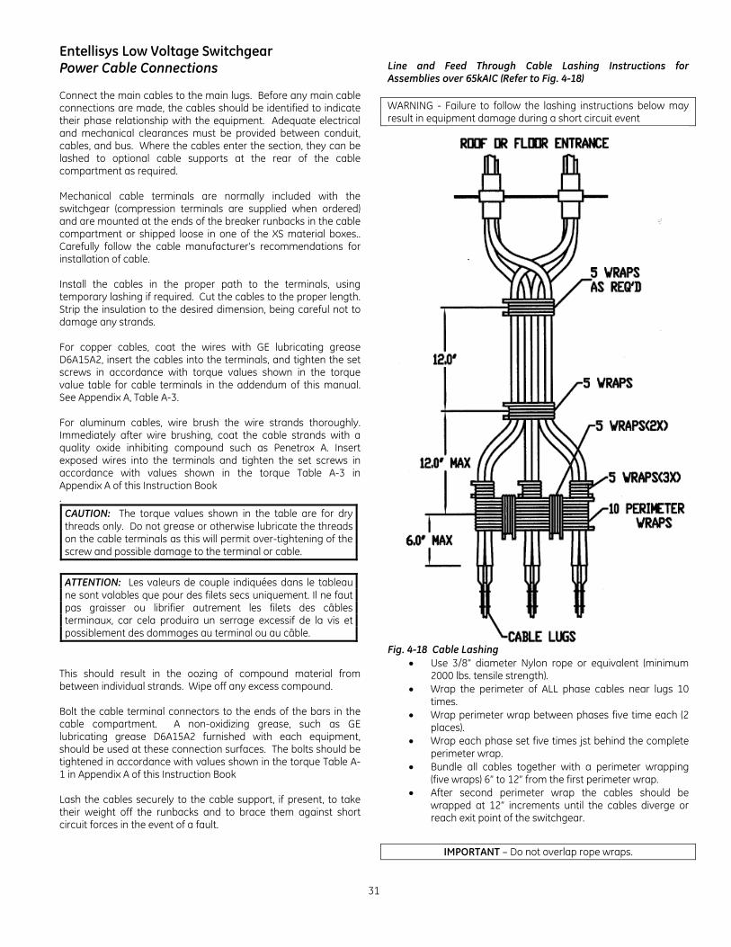
Line and Feed Through Cable Lashing Instructions for Assemblies over 65kAIC (Refer to Fig. 4-18) WARNING - Failure to follow the lashing instructions below may result in equipment damage during a short circuit event
Fig. 4-18 Cable Lashing
Use 3/8” diameter Nylon rope or equivalent (minimum 2000 lbs. tensile strength).
Wrap the perimeter of ALL phase cables near lugs 10 times.
Wrap perimeter wrap between phases five time each (2 places).
Wrap each phase set five times jst behind the complete perimeter wrap.
Bundle all cables together with a perimeter wrapping (five wraps) 6” to 12” from the first perimeter wrap.
After second perimeter wrap the cables should be wrapped at 12” increments until the cables diverge or reach exit point of the switchgear.
IMPORTANT – Do not overlap rope wraps.
32
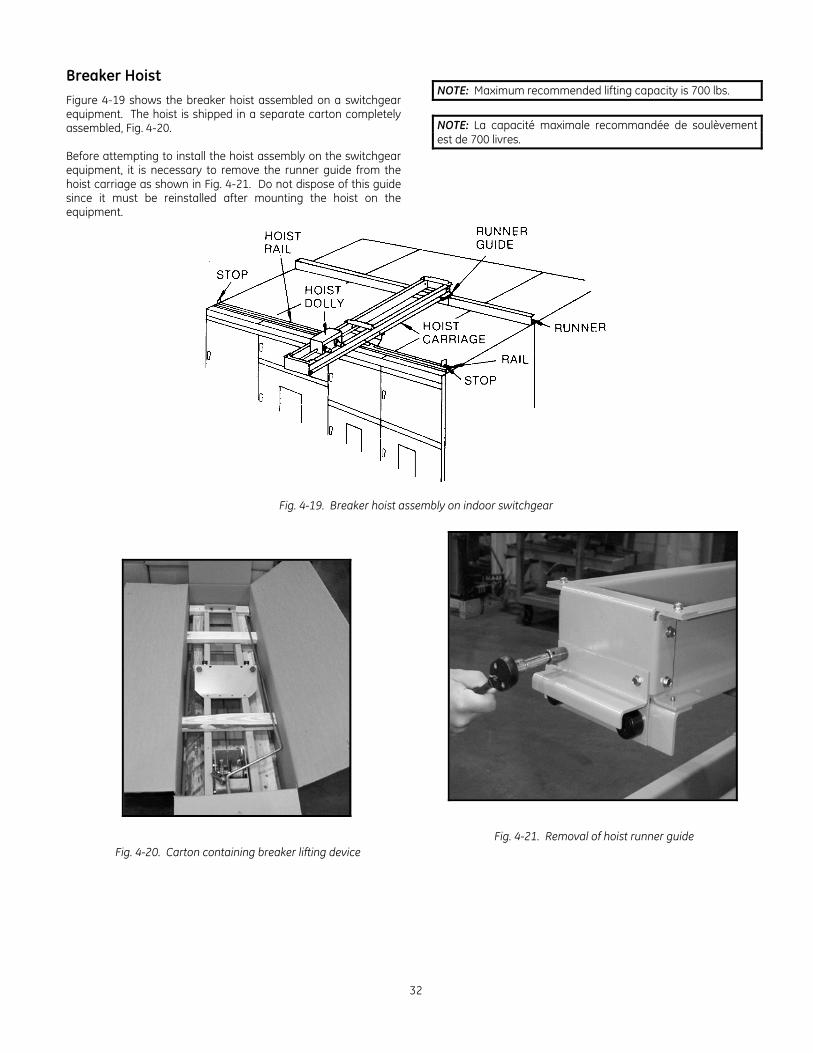
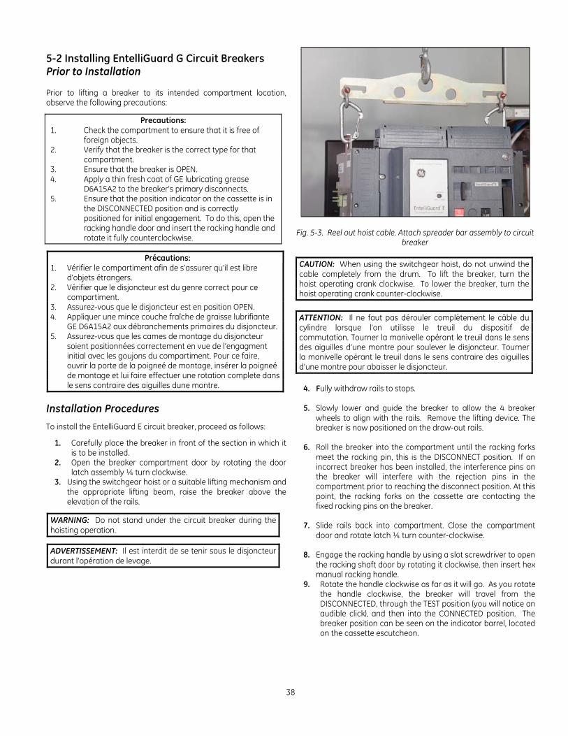
Breaker Hoist
Figure 4-19 shows the breaker hoist assembled on a switchgear equipment. The hoist is shipped in a separate carton completely assembled, Fig. 4-20. Before attempting to install the hoist assembly on the switchgear equipment, it is necessary to remove the runner guide from the hoist carriage as shown in Fig. 4-21. Do not dispose of this guide since it must be reinstalled after mounting the hoist on the equipment.
NOTE: Maximum recommended lifting capacity is 700 lbs.
NOTE: La capacité maximale recommandée de soulèvement est de 700 livres.
Fig. 4-19. Breaker hoist assembly on indoor switchgear
Fig. 4-20. Carton containing breaker lifting device
Fig. 4-21. Removal of hoist runner guide
Entellisys Low Voltage Switchgear
33
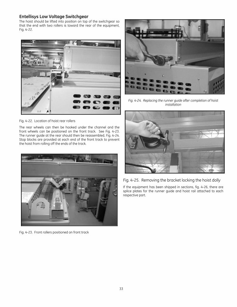
The hoist should be lifted into position on top of the switchgear so that the end with two rollers is toward the rear of the equipment, Fig. 4-22.
Fig. 4-22. Location of hoist rear rollers
The rear wheels can then be hooked under the channel and the front wheels can be positioned on the front track. See Fig. 4-23. The runner guide at the rear should then be reassembled, Fig. 4-24. Stop blocks are provided at each end of the front track to prevent the hoist from rolling off the ends of the track.
Fig. 4-23. Front rollers positioned on front track
Fig. 4-24. Replacing the runner guide after completion of hoist installation
Fig. 4-25. Removing the bracket locking the hoist dolly
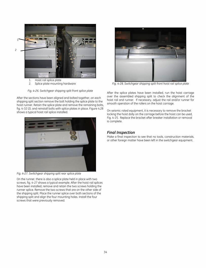
If the equipment has been shipped in sections, fig. 4-26, there are splice plates for the runner guide and hoist rail attached to each respective part.
34
1. Hoist rail splice plate 2. Splice plate mounting hardware
Fig. 4-26. Switchgear shipping split front splice plate
After the sections have been aligned and bolted together, on each shipping split section remove the bolt holding the splice plate to the hoist runner. Retain the splice plate and remove the remaining bolts, fig. 4-32 (2), and reinstall bolts with splice plates in place. Figure 4.28 shows a typical hoist rail splice installed.
Fig. 4-27. Switchgear shipping split rear splice plate
On the runner, there is also a splice plate held in place with two screws, fig. 4-27 shows a typical example. After the hoist rail splices have been installed, remove and retain the two screws holding the runner splice. Remove the two screws that are on the other side of the shipping split. Place the runner splice over both sections of the shipping split and align the four mounting holes. Install the four screws that were previously removed.
Fig. 4-28. Switchgear shipping split front hoist rail splice plate
After the splice plates have been installed, run the hoist carriage over the assembled shipping split to check the alignment of the hoist rail and runner. If necessary, adjust the rail and/or runner for smooth operation of the rollers on the hoist carriage. On seismic rated equipment, it is necessary to remove the bracket locking the hoist dolly on the carriage before the hoist can be used, Fig. 4-25. Replace the bracket after breaker installation or removal is complete. Final Inspection Make a final inspection to see that no tools, construction materials, or other foreign matter have been left in the switchgear equipment.
1
2
Entellisys Low Voltage Switchgear
35
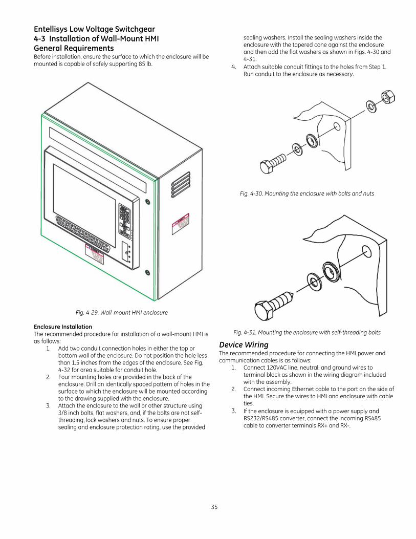
4-3 Installation of Wall-Mount HMI General Requirements Before installation, ensure the surface to which the enclosure will be mounted is capable of safely supporting 85 lb.
Fig. 4-29. Wall-mount HMI enclosure
Enclosure Installation The recommended procedure for installation of a wall-mount HMI is as follows:
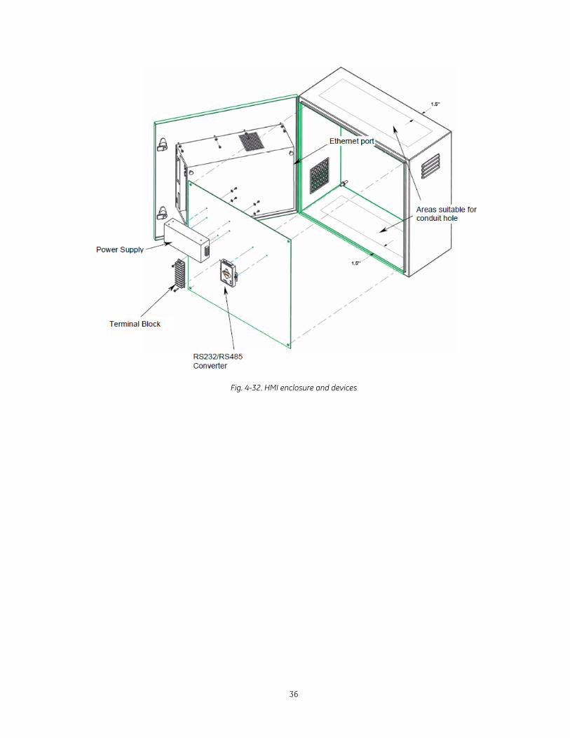
1. Add two conduit connection holes in either the top or bottom wall of the enclosure. Do not position the hole less than 1.5 inches from the edges of the enclosure. See Fig. 4-32 for area suitable for conduit hole.
2. Four mounting holes are provided in the back of the enclosure. Drill an identically spaced pattern of holes in the surface to which the enclosure will be mounted according to the drawing supplied with the enclosure.
3. Attach the enclosure to the wall or other structure using 3/8 inch bolts, flat washers, and, if the bolts are not self-threading, lock washers and nuts. To ensure proper sealing and enclosure protection rating, use the provided
sealing washers. Install the sealing washers inside the enclosure with the tapered cone against the enclosure and then add the flat washers as shown in Figs. 4-30 and 4-31.
4. Attach suitable conduit fittings to the holes from Step 1. Run conduit to the enclosure as necessary.
Fig. 4-30. Mounting the enclosure with bolts and nuts
Fig. 4-31. Mounting the enclosure with self-threading bolts
Device Wiring The recommended procedure for connecting the HMI power and communication cables is as follows:
1. Connect 120VAC line, neutral, and ground wires to terminal block as shown in the wiring diagram included with the assembly.
2. Connect incoming Ethernet cable to the port on the side of the HMI. Secure the wires to HMI and enclosure with cable ties.
3. If the enclosure is equipped with a power supply and RS232/RS485 converter, connect the incoming RS485 cable to converter terminals RX+ and RX-.
36
Fig. 4-32. HMI enclosure and devices
Entellisys Low Voltage Switchgear
37
5. Installing & Removing Circuit Breakers
5-1 General Inspection and Preparation of Circuit Breakers Before installing, operating, or removing a circuit breaker, refer to the breaker instruction manual for preparation, inspection, and test. Check thoroughly for damaged or loose parts and for any dirt or foreign matter which may be in the breaker. Be sure that a thin film of GE lubricating grease D6A15A2 is present on primary disconnects of the switchgear before installing the breaker.
Circuit Breaker Installation To install a circuit breaker, proceed as follows:
1. Before installing check the contact areas on each primary disconnect bar or cluster of fingers for foreign matter that may have accumulated. Clean these areas if necessary. Be sure that a thin film of GE lubricating grease D6A15A2 covers the contact areas before putting a breaker in the compartment.
2. Check to see that the breakers match their respective compartments. Each breaker is assigned a part or mark number. This number is shown on the breaker sheets of the summary, the front view drawings, and on the identification card on the breaker shipping carton. The breaker may also be identified using the 10 digit catalog number.
3. To locate the breaker in the proper compartment, refer to
the breaker location list on the front view drawing. Find the proper breaker by the identification card on the breaker carton. All identical breakers will have the same mark and catalog number.
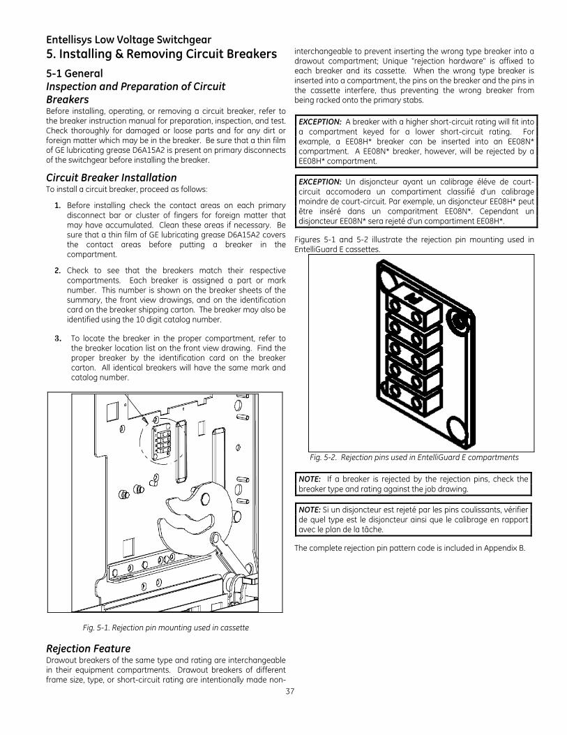
Fig. 5-1. Rejection pin mounting used in cassette
Rejection Feature Drawout breakers of the same type and rating are interchangeable in their equipment compartments. Drawout breakers of different frame size, type, or short-circuit rating are intentionally made non-
interchangeable to prevent inserting the wrong type breaker into a drawout compartment; Unique "rejection hardware" is affixed to each breaker and its cassette. When the wrong type breaker is inserted into a compartment, the pins on the breaker and the pins in the cassette interfere, thus preventing the wrong breaker from being racked onto the primary stabs.
EXCEPTION: A breaker with a higher short-circuit rating will fit into a compartment keyed for a lower short-circuit rating. For example, a EE08H* breaker can be inserted into an EE08N* compartment. A EE08N* breaker, however, will be rejected by a EE08H* compartment.
EXCEPTION: Un disjoncteur ayant un calibrage éléve de court-circuit accomodera un compartiment classifié d’un calibrage moindre de court-circuit. Par exemple, un disjoncteur EE08H* peut être inséré dans un comparitment EE08N*. Cependant un disjoncteur EE08N* sera rejeté d’un compartiment EE08H*.
Figures 5-1 and 5-2 illustrate the rejection pin mounting used in EntelliGuard E cassettes.
Fig. 5-2. Rejection pins used in EntelliGuard E compartments
NOTE: If a breaker is rejected by the rejection pins, check the breaker type and rating against the job drawing.
NOTE: Si un disjoncteur est rejeté par les pins coulissants, vérifier de quel type est le disjoncteur ainsi que le calibrage en rapport avec le plan de la tâche.
The complete rejection pin pattern code is included in Appendix B.
38
5-2 Installing EntelliGuard G Circuit Breakers Prior to Installation Prior to lifting a breaker to its intended compartment location, observe the following precautions:
Precautions: 1. Check the compartment to ensure that it is free of
foreign objects. 2. Verify that the breaker is the correct type for that
compartment. 3. Ensure that the breaker is OPEN. 4. Apply a thin fresh coat of GE lubricating grease
D6A15A2 to the breaker’s primary disconnects. 5. Ensure that the position indicator on the cassette is in
the DISCONNECTED position and is correctly positioned for initial engagement. To do this, open the racking handle door and insert the racking handle and rotate it fully counterclockwise.
Précautions: 1. Vérifier le compartiment afin de s’assurer qu’il est libre
d’objets étrangers. 2. Vérifier que le disjoncteur est du genre correct pour ce
compartiment. 3. Assurez-vous que le disjoncteur est en position OPEN. 4. Appliquer une mince couche fraîche de graisse lubrifiante
GE D6A15A2 aux débranchements primaires du disjoncteur. 5. Assurez-vous que les cames de montage du disjoncteur
soient positionnées correctement en vue de l’engagment initial avec les goujons du compartiment. Pour ce faire, ouvrir la porte de la poigneé de montage, insérer la poigneé de montage et lui faire effectuer une rotation complete dans le sens contraire des aiguilles dune montre.
Installation Procedures
To install the EntelliGuard E circuit breaker, proceed as follows:
1. Carefully place the breaker in front of the section in which it is to be installed.
2. Open the breaker compartment door by rotating the door latch assembly ¼ turn clockwise.
3. Using the switchgear hoist or a suitable lifting mechanism and the appropriate lifting beam, raise the breaker above the elevation of the rails.
WARNING: Do not stand under the circuit breaker during the hoisting operation.
ADVERTISSEMENT: Il est interdit de se tenir sous le disjoncteur durant l’opération de levage.
Fig. 5-3. Reel out hoist cable. Attach spreader bar assembly to circuit breaker
CAUTION: When using the switchgear hoist, do not unwind the cable completely from the drum. To lift the breaker, turn the hoist operating crank clockwise. To lower the breaker, turn the hoist operating crank counter-clockwise.
ATTENTION: Il ne faut pas dérouler complètement le câble du cylindre lorsque l’on utilisse le treuil du dispositif de commutation. Tourner la manivelle opérant le treuil dans le sens des aiguilles d’une montre pour soulever le disjoncteur. Tourner la manivelle opérant le treuil dans le sens contraire des aiguilles d’une montre pour abaisser le disjoncteur.
4. Fully withdraw rails to stops. 5. Slowly lower and guide the breaker to allow the 4 breaker
wheels to align with the rails. Remove the lifting device. The breaker is now positioned on the draw-out rails.
6. Roll the breaker into the compartment until the racking forks
meet the racking pin, this is the DISCONNECT position. If an incorrect breaker has been installed, the interference pins on the breaker will interfere with the rejection pins in the compartment prior to reaching the disconnect position. At this point, the racking forks on the cassette are contacting the fixed racking pins on the breaker.
7. Slide rails back into compartment. Close the compartment
door and rotate latch ¼ turn counter-clockwise. 8. Engage the racking handle by using a slot screwdriver to open
the racking shaft door by rotating it clockwise, then insert hex manual racking handle.
9. Rotate the handle clockwise as far as it will go. As you rotate the handle clockwise, the breaker will travel from the DISCONNECTED, through the TEST position (you will notice an audible click), and then into the CONNECTED position. The breaker position can be seen on the indicator barrel, located on the cassette escutcheon.
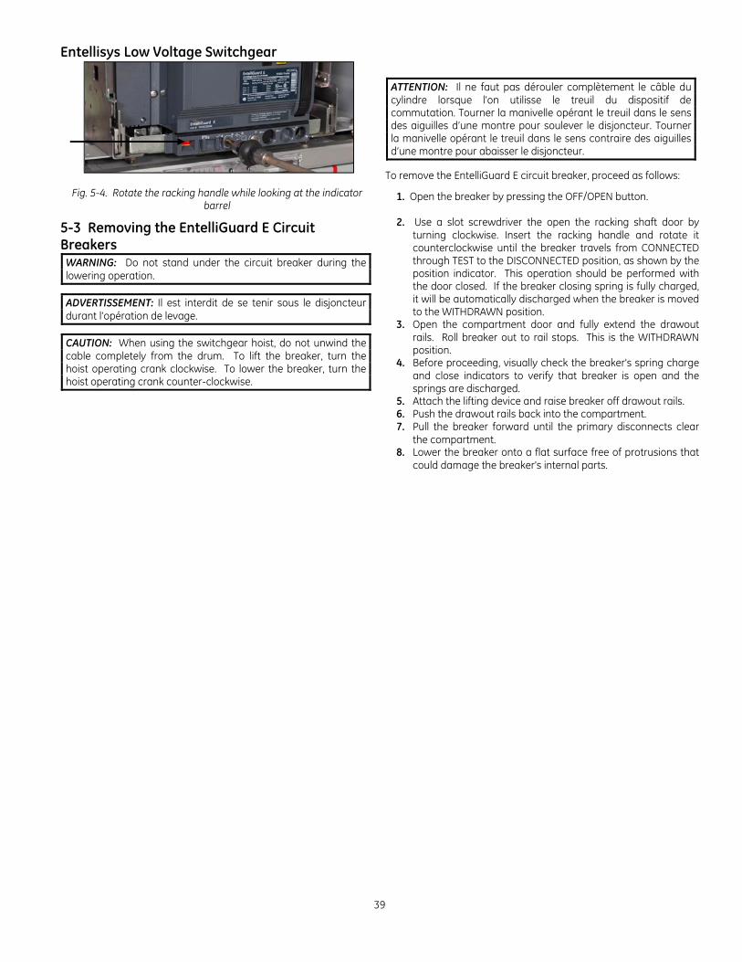
Entellisys Low Voltage Switchgear
39
Fig. 5-4. Rotate the racking handle while looking at the indicator barrel
5-3 Removing the EntelliGuard E Circuit Breakers
WARNING: Do not stand under the circuit breaker during the lowering operation.
ADVERTISSEMENT: Il est interdit de se tenir sous le disjoncteur durant l’opération de levage.
CAUTION: When using the switchgear hoist, do not unwind the cable completely from the drum. To lift the breaker, turn the hoist operating crank clockwise. To lower the breaker, turn the hoist operating crank counter-clockwise.
ATTENTION: Il ne faut pas dérouler complètement le câble du cylindre lorsque l’on utilisse le treuil du dispositif de commutation. Tourner la manivelle opérant le treuil dans le sens des aiguilles d’une montre pour soulever le disjoncteur. Tourner la manivelle opérant le treuil dans le sens contraire des aiguilles d’une montre pour abaisser le disjoncteur.
To remove the EntelliGuard E circuit breaker, proceed as follows:
1. Open the breaker by pressing the OFF/OPEN button.
2. Use a slot screwdriver the open the racking shaft door by turning clockwise. Insert the racking handle and rotate it counterclockwise until the breaker travels from CONNECTED through TEST to the DISCONNECTED position, as shown by the position indicator. This operation should be performed with the door closed. If the breaker closing spring is fully charged, it will be automatically discharged when the breaker is moved to the WITHDRAWN position.
3. Open the compartment door and fully extend the drawout rails. Roll breaker out to rail stops. This is the WITHDRAWN position.
4. Before proceeding, visually check the breaker's spring charge and close indicators to verify that breaker is open and the springs are discharged.
5. Attach the lifting device and raise breaker off drawout rails. 6. Push the drawout rails back into the compartment. 7. Pull the breaker forward until the primary disconnects clear
the compartment. 8. Lower the breaker onto a flat surface free of protrusions that
could damage the breaker's internal parts.
40
6. Testing & Inspection
6-1 General After the equipment has been installed and all connections made, it must be tested and inspected before it is put in service. Although the equipment and devices have been tested at the factory, a final field test must be made to be sure that the equipment has been properly installed and that all connections are correct.
WARNING: The equipment must be completely de-energized while the tests are in progress.
ADVERTISSEMENT: L’équipement doit être complètement désamorcé lorsque l’on procède à des tests.
Directions for testing Entellisys instrumentation is provided in DEH-501 (Entellisys System User’s Manual) and DEH-233 (Entellisys System Test Kit User’s Manual.) The proper settings of Entellisys instrumentation are normally determined from a complete power system coordination study performed by the purchaser or their consultant; therefore, the settings of these devices must be made by the purchaser.
NOTE: The trip setting adjustment of the EntelliGuard Messenger for each circuit breaker may be in any position when shipped from the factory and must be correctly positioned prior to energization of the equipment.
NOTE: Les ajustements des réglages du disjoncteur peuvent être en n’importe quelle position lorsque celui-ci est expédié de l’usine et ils doivent être positionnés correctement avant que l’équipement ne soit mis sous tension.
The extent of the tests on the equipment as a whole will depend on the type and function of the equipment. Tests that should be performed, however, include circuit breaker operation, and switchgear meggering, phasing, and grounding checks. High-potential tests to check the integrity of the insulation are not necessary if the installation instructions are carefully followed. If local codes demand this test, or the purchaser wishes to make high-potential tests, the voltage should not exceed 75 percent of the IEEE factory test voltage. For the power circuit, the IEEE factory test voltage is two times switchgear rating plus 1,000 volts. See Table 6-1. Potential and control power transformers must be disconnected during high-voltage testing.
Switchgear Voltage Rating
ANSI Test Voltage,
ac RMS
Field Test Voltage,
ac RMS 600V 480V 240V
2200V 1960V 1480V
1650V 1470V 1110V
Table 6-1
6-2 Key Interlocks After initial installation of the switchgear equipment, all necessary interlock keys should be inserted into the appropriate locks and all spare keys should be stored in a location in accordance with the owner's established procedures.
CAUTION: Refer to the key interlock schematic included in the summary furnished with the equipment to determine the sequence of operation and the correct number of operating keys required. This precaution is necessary since the improper use of spare keys will defeat the interlocking scheme.
ATTENTION: Référez-vous au schéma des clés de verrouillage inclus au sommaire fourni avec l’équipement pour déterminer les séquences d’opération et le nombre correct de clés d’opération requises. Cette précaution est nécessaire étant donné qu’un mauvais usage des clés de réserve rendra inopérant le programme de verrouillage.
6-3 Breaker Operation Test All compartments housing EntelliGuard circuit breakers have a TEST position in which the breaker primary contacts are disconnected while the secondary contacts are still engaged. This TEST position permits complete testing of the electrical control circuit without energizing the primary power circuit. When the breaker is first put into service, its control circuit must be thoroughly tested while in this position to make sure that all closing and tripping circuits are complete and functioning properly. The TEST position is not suitable for inspection and maintenance of the breaker and should therefore be used only for testing breaker operation. Refer to the appropriate breaker instruction manual for other pre-operational checks on the breakers. See DEH-41526.
6-4 Entellisys System Test Kit An Entellisys System Test Kit is required for testing Entellisys Low Voltage Switchgear functionality. The system test kit user manual is DEH-233.
6-5 Final Steps to Be Taken Before Energizing Equipment The following steps should be taken before energizing the equipment:
1. Manually exercise all switches, circuit breakers, and other operating mechanisms to make certain they are properly aligned and operate freely.
2. Conduct an electrical insulation resistance test to
make sure the switchgear is free from short circuits and grounds. This should be done both phase-to-ground and phase-to-phase with the switches or circuit breakers both opened and

Entellisys Low Voltage Switchgear
41
closed. This test should be performed with a 1000 volt megger. Disconnect all control circuits before checking resistance.
3. Check for secure mounting and wiring connections at Entellisys instrumentation.
4. Using the Entellisys HMI, exercise all
EntelliGuard breakers to determine all devices work correctly. See DEH-501 for instructions on using the Entellisys HMI.
5. Test all protection functions using the Entellisys System Test Kit. See DEH-233 for instructions.
6. Make certain that field wiring is clear of live bus and, where necessary, physically secured to withstand the effects of fault currents.
7. Check to determine that all grounding connections are made properly.
8. Remove all debris, scrap wire, etc., from the switchgear interior before closing the enclosure.
9. Install covers, close doors, and make certain that no wires are pinched and that all enclosure parts are properly aligned and tightened.
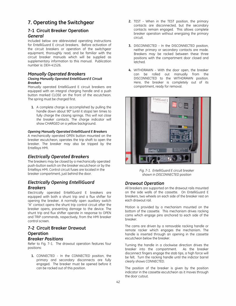
42
7. Operating the Switchgear
7-1 Circuit Breaker Operation General Included below are abbreviated operating instructions for EntelliGuard E circuit breakers. Before activation of the circuit breakers or operation of the switchgear equipment, thoroughly read, and be familiar with the circuit breaker manuals which will be supplied as supplementary information to this manual. Publication number is: DEH-41526. Manually Operated Breakers Closing Manually Operated EntelliGuard E Circuit Breakers Manually operated EntelliGuard E circuit breakers are equipped with an integral charging handle and a push button marked CLOSE on the front of the escutcheon. The spring must be charged first.
1. A complete charge is accomplished by pulling the handle down about 90° (until it stops) ten times to fully charge the closing springs. This will not close the breaker contacts. The charge indicator will show CHARGED on a yellow background.
Opening Manually Operated EntelliGuard E Breakers A mechanically operated OPEN button mounted on the breaker escutcheon, operates the trip shaft to open the breaker. The breaker may also be tripped by the Entellisys HMI. Electrically Operated Breakers The breakers may be closed by a mechanically operated push-button switch on the breaker escutcheon or by the Entellisys HMI. Control circuit fuses are located in the breaker compartment, just behind the door.
Electrically Opening EntelliGuard Breakers Electrically operated EntelliGuard E breakers are equipped with both a shunt trip and a flux shifter for opening the breaker. A normally open auxiliary switch “A” contact opens the shunt trip control circuit after the breaker opens, preventing damage to the device. The shunt trip and flux shifter operate in response to OPEN and TRIP commands, respectively, from the HMI breaker control screen.
7-2 Circuit Breaker Drawout Operation Breaker Positions Refer to Fig. 7-1. The drawout operation features four positions:
1. CONNECTED - In the CONNECTED position, the primary and secondary disconnects are fully engaged. The breaker must be opened before it can be racked out of this position.
2. TEST - When in the TEST position, the primary contacts are disconnected, but the secondary contacts remain engaged. This allows complete breaker operation without energizing the primary circuit.
3. DISCONNECTED - In the DISCONNECTED position,
neither primary or secondary contacts are made. Breakers may be racked between these three positions with the compartment door closed and latched.
4. WITHDRAWN - With the door open, the breaker
can be rolled out manually from the DISCONNECTED to the WITHDRAWN position. Here, the breaker is completely out of its compartment, ready for removal.
Fig. 7-1. EntelliGuard E circuit breaker shown in DISCONNECTED position
Drawout Operation All breakers are supported on the drawout rails mounted on the side walls of the cassette. On EntelliGuard E breakers, two wheels on each side of the breaker rest on each drawout rail.
Motion is provided by a mechanism mounted on the bottom of the cassette. This mechanism drives racking cams which engage pins anchored to each side of the breaker.
The cams are driven by a removable racking handle or remote racker which engages the mechanism. The handle is inserted through an opening in the cassette escutcheon below the breaker.
Turning the handle in a clockwise direction drives the breaker into the compartment. As the breaker disconnect fingers engage the stab tips, a high force will be felt. Turn the racking handle until the indictor barrel clearly shows CONNECTED.
The position of the breaker is given by the position indicator in the cassette escutcheon as it moves through the door cutout.
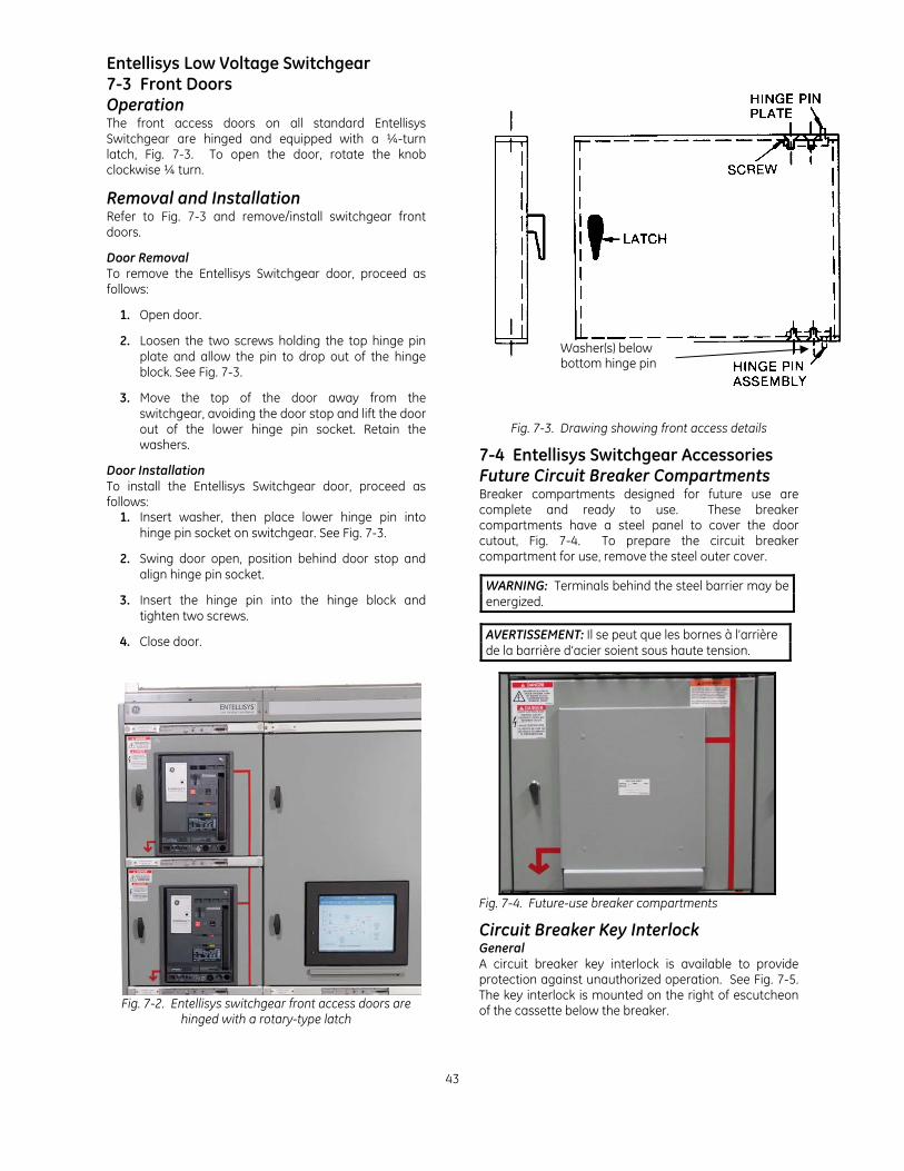
Entellisys Low Voltage Switchgear
43
7-3 Front Doors Operation The front access doors on all standard Entellisys Switchgear are hinged and equipped with a ¼-turn latch, Fig. 7-3. To open the door, rotate the knob clockwise ¼ turn.
Removal and Installation Refer to Fig. 7-3 and remove/install switchgear front doors.
Door Removal To remove the Entellisys Switchgear door, proceed as follows:
1. Open door.
2. Loosen the two screws holding the top hinge pin plate and allow the pin to drop out of the hinge block. See Fig. 7-3.
3. Move the top of the door away from the switchgear, avoiding the door stop and lift the door out of the lower hinge pin socket. Retain the washers.
Door Installation To install the Entellisys Switchgear door, proceed as follows:
1. Insert washer, then place lower hinge pin into hinge pin socket on switchgear. See Fig. 7-3.
2. Swing door open, position behind door stop and align hinge pin socket.
3. Insert the hinge pin into the hinge block and tighten two screws.
4. Close door.
Fig. 7-2. Entellisys switchgear front access doors are
hinged with a rotary-type latch
Fig. 7-3. Drawing showing front access details
7-4 Entellisys Switchgear Accessories Future Circuit Breaker Compartments Breaker compartments designed for future use are complete and ready to use. These breaker compartments have a steel panel to cover the door cutout, Fig. 7-4. To prepare the circuit breaker compartment for use, remove the steel outer cover.
WARNING: Terminals behind the steel barrier may be energized.
AVERTISSEMENT: Il se peut que les bornes à l’arrière de la barrière d’acier soient sous haute tension.
Fig. 7-4. Future-use breaker compartments
Circuit Breaker Key Interlock General A circuit breaker key interlock is available to provide protection against unauthorized operation. See Fig. 7-5. The key interlock is mounted on the right of escutcheon of the cassette below the breaker.
Washer(s) below bottom hinge pin
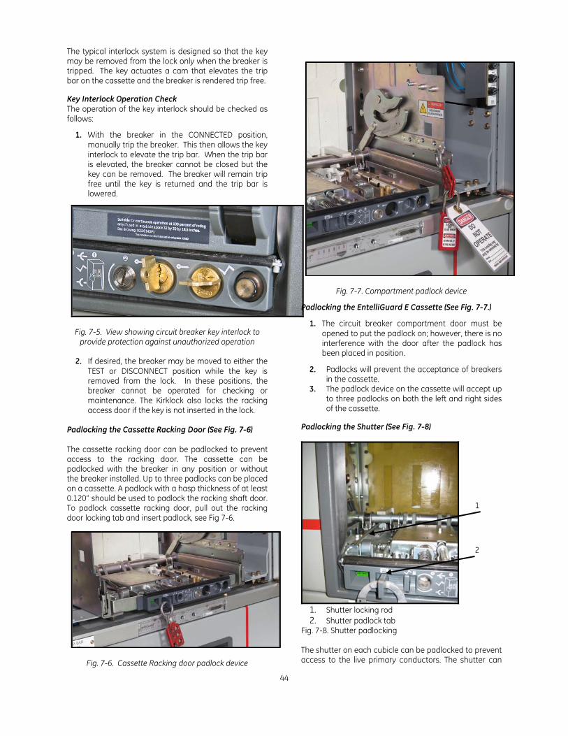
44
The typical interlock system is designed so that the key may be removed from the lock only when the breaker is tripped. The key actuates a cam that elevates the trip bar on the cassette and the breaker is rendered trip free. Key Interlock Operation Check The operation of the key interlock should be checked as follows:
1. With the breaker in the CONNECTED position, manually trip the breaker. This then allows the key interlock to elevate the trip bar. When the trip bar is elevated, the breaker cannot be closed but the key can be removed. The breaker will remain trip free until the key is returned and the trip bar is lowered.
Fig. 7-5. View showing circuit breaker key interlock to provide protection against unauthorized operation
2. If desired, the breaker may be moved to either the
TEST or DISCONNECT position while the key is removed from the lock. In these positions, the breaker cannot be operated for checking or maintenance. The Kirklock also locks the racking access door if the key is not inserted in the lock.
Padlocking the Cassette Racking Door (See Fig. 7-6) The cassette racking door can be padlocked to prevent access to the racking door. The cassette can be padlocked with the breaker in any position or without the breaker installed. Up to three padlocks can be placed on a cassette. A padlock with a hasp thickness of at least 0.120” should be used to padlock the racking shaft door. To padlock cassette racking door, pull out the racking door locking tab and insert padlock, see Fig 7-6.
Fig. 7-6. Cassette Racking door padlock device
Fig. 7-7. Compartment padlock device
Padlocking the EntelliGuard E Cassette (See Fig. 7-7.)
1. The circuit breaker compartment door must be opened to put the padlock on; however, there is no interference with the door after the padlock has been placed in position.
2. Padlocks will prevent the acceptance of breakers in the cassette.
3. The padlock device on the cassette will accept up to three padlocks on both the left and right sides of the cassette.
Padlocking the Shutter (See Fig. 7-8)
1. Shutter locking rod 2. Shutter padlock tab
Fig. 7-8. Shutter padlocking The shutter on each cubicle can be padlocked to prevent access to the live primary conductors. The shutter can
1
2

Entellisys Low Voltage Switchgear
45
be padlocked without the breaker installed. One padlock can be placed on a cassette. To padlock shutter, pull out the shutter locking tab and insert padlock, see Fig 7-8. Pulling out the shutter locking tab actuates a rod (1) that goes through stationary and moving shutter parts that prevents it from opening. Installing and Removing Current Transformers
WARNING: Do not operate any current transformer with secondaries open-circuited. Be sure to short-circuit secondary before moving a current transformer.
AVERTISSEMENT: Tout transformateur de courant ne doit pas être opéré avec les secondaires dans un état de circuits ouverts. Assurez-vous de court-circuiter les secondaires avant de bouger un transformateur de courant.
Phase current transformers (CT's) in Entellisys Low Voltage Switchgear are mounted on the stationary primary disconnect studs in the breaker compartment. Neutral current transformers, if present, are located in the bus compartment or in the transition section. Care must be exercised when installing or removing phase current transformer mounting screws so as not to strip the holes in the plastic base. Do not torque screws over five in/lbs. Removing EntelliGuard E Shutter Units (on a de-engergized cubicle) Visual inspection of primary stab tips can be made by first removing the breaker and opening the shutters manually. This is done by rotating the actuating lever that opens the shutter (See Fig. 7-9). If it is necessary to perform work on the primary disconnects, the shutter unit and the stab tip bracing must be removed. To remove the shutter, remove the four screws in the corners of the shutter and carefully remove shutter unit.
WARNING: Unless the proper precautions are taken, the removal of a shutter unit presents the hazard of electrical shock and burn. Do not remove the shutter unit unless the equipment has been de-energized. Failure to do this can result in serious injury.
ADVERTISSEMENT: A moins que les précautions nécessaires ne soient prises, l’installation d’une unité à volet présente des risques de choc électrique ou de brûlure. Il ne faut pas installer l’unité à volet à moins que l’équipement ait été désamorcé. L’omission de ce faire peut résulter en blessures sérieuses.
To remove these shutter units, proceed as follows: 1. The shutter is mounted by four screws on the
horizontal stab tip braces located at each side of the rear of the breaker compartment. See Fig. 7-9.
2. Take out two slotted head screws on each side of the frame and carefully remove the shutter unit.
3. Carefully remove the entire shutter frame. 4. The frame is then maneuvered forward past the
racking cams on each side, then upward and forward out of the cassette.
1. Breaker Position Barrel Indicator 2. Shutters 3. Shutter actuator
Fig. 7-10. Entellisys circuit breaker shutter unit
Installing an EntelliGuard E Shutter Unit (in a de-energized cubicle)
Screws for removing
shutter assembly
Shutter actuating
lever
Fig. 7-9 Envelope 1 & Envelope 2 shutter assembly
2
3
1
46
WARNING: Unless the proper precautions are taken, the installation of a shutter unit presents the hazard of electrical shock and burn. Do not install the shutter unit unless the equipment has been de-energized. Failure to do this can result in serious injury.
ADVERTISSEMENT: A moins que les précautions nécessaires ne soient prises, l’installation d’une unité à volet présente des risques de choc électrique ou de brûlure. Il ne faut pas installer l’unité à volet à moins que l’équipement ait été désamorcé. L’omission de ce faire peut résulter en blessures sérieuses.
To install these shutter units, proceed as follows:
1. Carefully maneuver the shutter frame into the compartment, first lifting it over the racking cams on each side wall of the cassette. Make sure the shutter fits over the shutter actuator at the bottom of the cassette.
2. Position the shutter frame against the stab tip
braces and align the holes with the stand-off on the braces.
3. After the holes are aligned with the threaded stand offs, attach the shutter in 4 corner locations using the bolts supplied.
4. Check the operation of the moveable shutters by
actuating the shutter lever on the bottom of the cassette.
Entellisys Low Voltage Switchgear
47
8. Energizing the Switchgear
8-1 Before Energizing Before switchgear is energized, a thorough final check should be made using the following checklist: Refer to section 6-5 for additional information.
• Breakers and other operating mechanisms exercised • Electrical insulation resistance tested phase-to- phase and phase-to-ground • Entellisys instrumentation properly connected. • Electrically operated breakers and operating mechanisms exercised • Ground fault protection system tested • Protection settings properly set and tested. • Field wiring secured and free of live bus • Grounding connections made • All debris, scrap wire, etc. removed • All covers installed, doors closed and latched
8-2 Energizing Procedures
CAUTION: Energizing switchgear for the first time is potentially dangerous. Therefore, qualified electrical personnel should be present when the equipment is energized. If problems caused by damage or poor installation practices have not been detected in the checkout procedure described previously, serious damage can result when power is turned on.
ATTENTION: La mise sous tension pour la première fois d’un dispositif de commutation est un acte potentiellement dangereux. Il faut donc que du personnel qualifié en électricité soit présent lorsque l’équipement est mis sous tension. Si lors de la procédure de vérification décrite précédemment des problèmes causés par des dommages ou de mauvaises pratiques d’installation n’ont pas été détectés, il peut en résulter des dommages sérieux lorsque le contact est établi.
1. There should be no load on the switchgear when it is
energized.
2. Turn off all of the downstream loads, including those such as motor control centers and other devices which are remote from the switchgear.
3. The equipment should be energized in sequence by starting at the source end of the system and working toward the load end. In other words, energize the main devices, then the feeder devices, and then the branch-circuit devices.
4. Turn the devices on using Entellisys HMI.
48
9. Maintaining the Switchgear
9-1 Maintenance Requirements General A periodic maintenance schedule must be established to obtain the best service from the switchgear. An annual check of the switchgear devices and all connections should be made as a minimum requirement. Equipment subject to highly repetitive operation may require more frequent maintenance. A permanent record of all maintenance work should be kept. The record should include a list of periodic checks and tests made, the date they were made, the condition of the equipment, and any repairs or adjustments that were performed. Maintenance employees must follow all recognized safety practices, such as those contained in NFPA 70B: Electrical Equipment Maintenance, and NFPA 70E: Standard for Electrical Safety in the Workplace and in company or other safety regulations.
WARNING: Solid insulation surrounding an energized conductor and power apparatus must never be relied upon to provide protection to personnel.
ADVERTISSEMENT: Il ne faut pas se fier à une isolation solide entourant un conducteur mis sous tension et à la puissance de l’appareillage pour fournir une protection aux membres du personnel.
For specific information regarding the maintenance of circuit breakers and Entellisys instrumentation, refer to the instruction book furnished with each device.
9-2 Breaker and Instrument Compartments Periodic inspection of the circuit breaker is recommended at least once a year. More frequent inspections are recommended where severe load conditions, dust, moisture or other unfavorable conditions exist, or if the vital nature of the load warrants it. Always inspect the breaker after a short-circuit current has been interrupted.
Breakers Test for Proper Operation Test and inspect all circuit breakers for proper operation as follows:
1. Operate each breaker while in the TEST position and check all functions. This is particularly important for breakers that normally remain in either the opened or closed positions for long periods of time.
WARNING: Primary equipment must be completely de-energized while tests on control circuits, etc. are being conducted. Be sure that all areas of feedback from secondary circuits, as well as outside sources, are disconnected.
ADVERTISSEMENT: Il faut que l’équipement primaire soit complètement désamorcé lorsque des tests sont effectués sur des circuits de contrôle, etc. Assurez-vous que toutes les aires de rétroaction des circuits secondaires de même que les sources extérieures soient débranchées.
2. Remove the breakers from their compartments to a clean maintenance area. Close compartment door and cover the breaker cutout to prevent access to live parts.
WARNING: De-energize equipment completely before doing maintenance work on any devices, connections, bus work, breaker or feeder cable compartments. This includes de-energizing any connections to outside primary or secondary sources, such as transformers, tie lines, etc.
ADVERTISSEMENT: Désamorcer complètement l’équipement avant d’effectuer du travail de maintenance dans les compartiments. Cela inclut le désamorçage de toute connexion aux sources primaires et secondaires, telles que les transformateurs et les interconnexions.
Checks After Breaker Is De-energized At the time of inspection, the following checks should be made after the breaker has been de-energized.
1. Manually operate the breaker several times, checking for obstructions or excessive friction. Manual closing of an electrically operated breaker may be performed by the following two steps:
a. To charge the mechanism springs, pull the operating handle down until it stops (about 90°) ten times for the EntelliGuard E breaker. The charge indicator will show CHARGED on a yellow background.
b. Depress the CLOSE button on the front of the breaker.
The springs should discharge and, if the latch is properly reset, the breaker will close.
2. Electrically operate the breaker several times to check
performance of the electrical accessories. 3. Visually check the breaker for loose hardware on the
breaker; also, check the bottom of the compartment for any hardware that has fallen from the breaker.
4. Remove and inspect the arc quenchers and contacts for
breakage or excessive burning. 5. Check insulating parts for evidence of overheating and for
cracks that indicate excessive thermal aging. Refer to circuit breaker instruction manuals for detailed maintenance instructions and information for replacement of parts. See DEH-41526.
Lubrication In general, the circuit breaker requires moderate lubrication. Bearing points and sliding surfaces should be lubricated at the regular inspection periods with a thin film of GE lubricant D6A15A2. Before lubricating, remove any hardened grease and dirt from latch and bearing surfaces with mineral spirits then wipe with a clean rag.
CAUTION: All excess lubricant should be removed with a clean cloth to avoid accumulation of dirt or dust.
ATTENTION: Il faut enlever complètement tout excès de lubrifiant avec un linge propre afin d’éviter l’accumulation de saletés ou de poussières.
The contact surface of the disconnect fingers should be cleaned and greased with GE lubricant D6A15A2.
Entellisys Instrumentation and Instrument Transformers
Entellisys Low Voltage Switchgear
49
Check and inspect all devices to see that they are functioning properly. Check that all electrical connections are tight. Check mounting of the device. Breaker Compartment Interiors
WARNING: De-energize equipment completely before doing maintenance work in compartments. This includes de-energizing any connections to outside primary or secondary sources, such as transformers, tie lines, etc.
ADVERTISSEMENT: Mettre l’équipement complètement hors tension avant d’entreprendre tout travail de maintenance sur tout dispositif, raccordement, barres omnibus ou les compartiments des câbles d’alimentation. Cela inclut la mise hors tension des raccordements aux sources primaires et secondaires tels que les transformateurs et les interconnexions.
1. Thoroughly clean the interior of the breaker and instrument compartments. Use a vacuum cleaner and clean rags only. Do not use steel wool or oxide papers. Blowing with compressed air is not recommended.
2. Check indicating devices, mechanical and key interlocks. 3. Check primary disconnecting device contacts for signs of
abnormal wear or overheating. Discoloration of the silvered surfaces is not ordinarily harmful. These contacts should be cleaned only by wiping with a lint-free cloth.
4. Clean the racking mechanism and lubricate with GE lubricant D6A15A2.
5. Before replacing the breaker, wipe off the primary disconnecting device contacts. Apply a thin coat of GE lubricant D6A15A2 to the stationary studs and to the primary disconnects on the breaker.
9-3 Bus Area
WARNING: De-energize equipment completely before doing maintenance work on any devices, connections, bus work, breaker or feeder cable compartments. This includes de-energizing any connections to outside primary or secondary sources, such as transformers, tie lines, etc.
ADVERTISSEMENT: Désamorcer complètement l’équipement avant d’effectuer du travail de maintenance dans les compartiments. Cela inclut le désamorçage de toute connexion aux sources primaires et secondaires, telles que les transformateurs et les interconnexions.
Inspect and check the bus area as follows:
1. Inspect the buses and connections carefully for evidence of overheating or weakening of the insulating supports. If bus insulation is present, remove the molded covers over the main bus connection to expose joints for inspection.
2. Check all connection bolts in the bus compartment and all bracing bolts for tightness. See the Torque Table A-1 in Appendix A.
3. Vacuum and, with a clean rag, wipe the buses and supports.
4. Visually inspect the insulation on the bars that run from the breaker studs through the bus structure to the cable area.
5. After cleaning, megger and record the resistance to ground and between phases of all insulated bars and all
buses and connections. Disconnect all control circuits before checking resistance. Do not use over a 1500-volt megger. Since definite limits cannot be given for satis-factory insulation resistance values, a record must be kept of the readings.
Weakening of the insulation from one maintenance period to the next can be recognized from the recorded readings. The readings should be taken under similar conditions each time, if possible, and the record should include the ambient temperature and humidity.
9-4 Cable and Busway Compartment Inspect and check the cable and busway compartment as follows:
1. Inspect all power cable connections for signs of overheating and tighten all connections. If severe discoloration or if damage is apparent, remove the damaged portion of the cable.
CAUTION: Be sure the condition which caused the over-heating has been corrected before energizing.
ATTENTION: Assurez-vous que la condition ayant causé le surchauffement a été corrigée avant de mettre sous tension.
2. Check all bolts that hold cable terminals to the connection bars for tightness.
3. Check the neutral bus and ground bus connection and mounting bolts for tightness.
4. Check that all secondary control wiring connections are tight and that all control cabling is intact.
9-5 Overall Switchgear Make the following checks on the complete switchgear equipment.
1. Clean and inspect all painted surfaces and retouch where necessary.
2. Check to see that all anchor bolts and other structural
bolts are tight. 3. Check that all breaker and instrument compartment door
latches operate properly. 4. If the switchgear is equipped with heaters, check to see
that all heaters are energized and operating. 5. For exterior vent openings in equipment furnished with air
filters, the foam filter elements should be removed and washed in warm soapy water, rinsed, and reassembled at least annually. Elements should be inspected before re-assembly and replaced if any signs of deterioration are evident.
50
9-6 Paint Refinishing Indoor switchgear is finished with ANSI-61 gray polyester powder coat that is TGIC free. To refinish damaged areas, remove all loose paint, rust, scale, oil or grease. Make sure area is dry. Sand any scratches smooth using 220 grit paper or finer. Remove all dust from the area to be repaired. All paint work should be done only when the temperature is above 55 degrees F. - Scratches and small, damaged areas can be painted with a touch up can of spray paint of matching color.
This spray can, or more if needed, can be obtained from the GE Burlington, Iowa facility or the GE Mt. Juliet, Tennessee facility by using GE One Stop and ordering Catalogue Number TSP-61 GE Gray Touch Up Paint.
—Apply a coat of good acrylic enamel primer (Sherman-Williams E61 A 60,-GE part number 21525025200) with a viscosity of approximately 24-32 seconds using a #2 Zahn cup. Reduce with D5B9 Xylol (GE part number 21525038000) if needed. Air dry the primer for a minimum of 30 minutes, then apply the finish color coat of acrylic enamel. The top coat should be applied within 24 hours for best adhesion. —If the area is to be spray-coated, thin the acrylic enamel with D5B9 Xylol (GE part number 21525038000). This thinning should only be necessary if the paint was received in a five gallon drum or more. The recommended viscosity for the W42713 topcoat should be 24-32 seconds with a #2 Zahn cup. The curing schedule for PPG W42713 is dust free in 5 minutes, touch in 30 minutes, handle in 60 minutes, full cure in 7 days. Both the primer (Sherwin-Williams E61 A 60) and paint (PPG W42713) should be applied only when temperature is above 55 degrees Fahrenheit. —Application of special paint will be per the manufacturer’s Product Data Sheet which includes instructions on thinning and application.
9-7 Circuit Breaker Lifting Mechanism
Under normal conditions, no special maintenance procedures or lubrication is required for this device. If the cable is abraided under any condition, it should be inspected for broken strands or other damage and replaced if necessary.
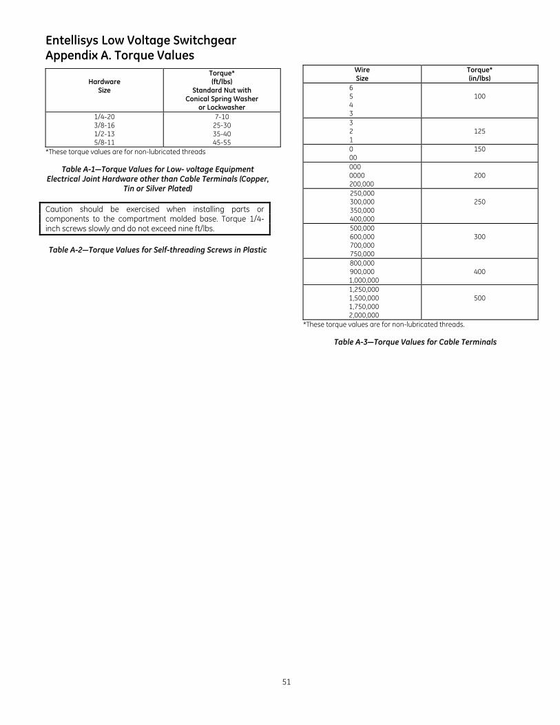
Entellisys Low Voltage Switchgear
51
Appendix A. Torque Values
Hardware Size
Torque* (ft/lbs)
Standard Nut with Conical Spring Washer
or Lockwasher 1/4-20 3/8-16 1/2-13 5/8-11
7-10 25-30 35-40 45-55
*These torque values are for non-lubricated threads
Table A-1—Torque Values for Low- voltage Equipment Electrical Joint Hardware other than Cable Terminals (Copper,
Tin or Silver Plated)
Caution should be exercised when installing parts or components to the compartment molded base. Torque 1/4-inch screws slowly and do not exceed nine ft/lbs.
Table A-2—Torque Values for Self-threading Screws in Plastic
Wire Size
Torque* (in/lbs)
6 5 4 3
100
3 2 1
125
0 00
150
000 0000 200,000
200
250,000 300,000 350,000 400,000
250
500,000 600,000 700,000 750,000
300
800,000 900,000
1,000,000
400
1,250,000 1,500,000 1,750,000 2,000,000
500
*These torque values are for non-lubricated threads.
Table A-3—Torque Values for Cable Terminals
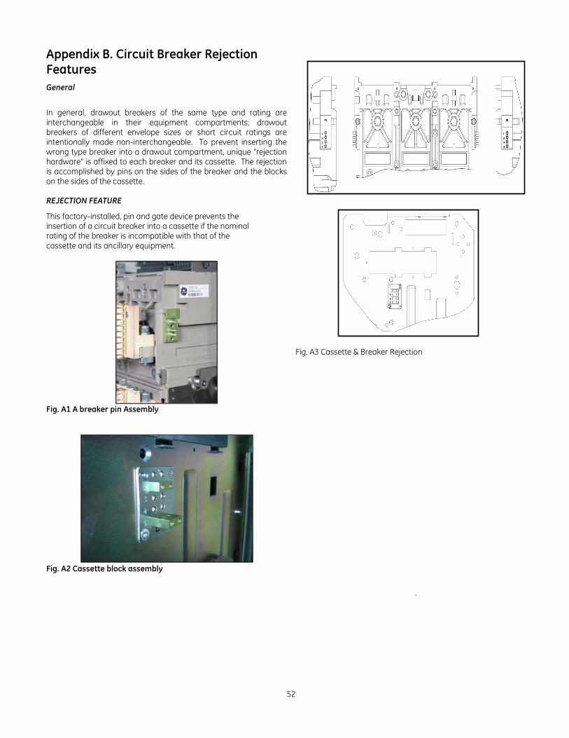
52
Appendix B. Circuit Breaker Rejection Features General In general, drawout breakers of the same type and rating are interchangeable in their equipment compartments; drawout breakers of different envelope sizes or short circuit ratings are intentionally made non-interchangeable. To prevent inserting the wrong type breaker into a drawout compartment, unique “rejection hardware” is affixed to each breaker and its cassette. The rejection is accomplished by pins on the sides of the breaker and the blocks on the sides of the cassette.
REJECTION FEATURE
This factory-installed, pin and gate device prevents the insertion of a circuit breaker into a cassette if the nominal rating of the breaker is incompatible with that of the cassette and its ancillary equipment.
Fig. A1 A breaker pin Assembly
Fig. A2 Cassette block assembly
Fig. A3 Cassette & Breaker Rejection
.
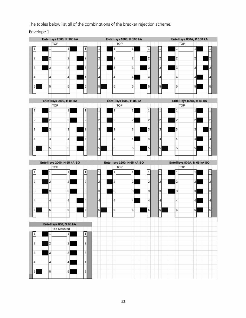
53
The tables below list all of the combinations of the breaker rejection scheme.
Envelope 1
TOP TOP TOP
1 1 1 1 1 1 1 1 1 1 1 1
2 2 2 2 2 2 2 2 2 2 2 2
3 3 3 3 3 3 3 3 3 3 3 3
4 4 4 4 4 4 4 4 4 4 4 4
5 5 5 5 5 5 5 5 5 5 5 5
TOP TOP TOP
1 1 1 1 1 1 1 1 1 1 1 1
2 2 2 2 2 2 2 2 2 2 2 2
3 3 3 3 3 3 3 3 3 3 3 3
4 4 4 4 4 4 4 4 4 4 4 4
5 5 5 5 5 5 5 5 5 5 5 5
TOP TOP TOP
1 1 1 1 1 1 1 1 1 1 1 1
2 2 2 2 2 2 2 2 2 2 2 2
3 3 3 3 3 3 3 3 3 3 3 3
4 4 4 4 4 4 4 4 4 4 4 4
5 5 5 5 5 5 5 5 5 5 5 5
Top Mounted
1 1 1 1
2 2 2 2
3 3 3 3
4 4 4 4
5 5 5 5
Entellisys 800, S 65 kA
Entellisys 2000, H 85 kA Entellisys 1600, H 85 kA Entellisys 800A, H 85 kA
Entellisys 2000, N 65 kA SQ Entellisys 1600, N 65 kA SQ Entellisys 800A, N 65 kA SQ
Entellisys 2000, P 100 kA Entellisys 1600, P 100 kA Entellisys 800A, P 100 kA
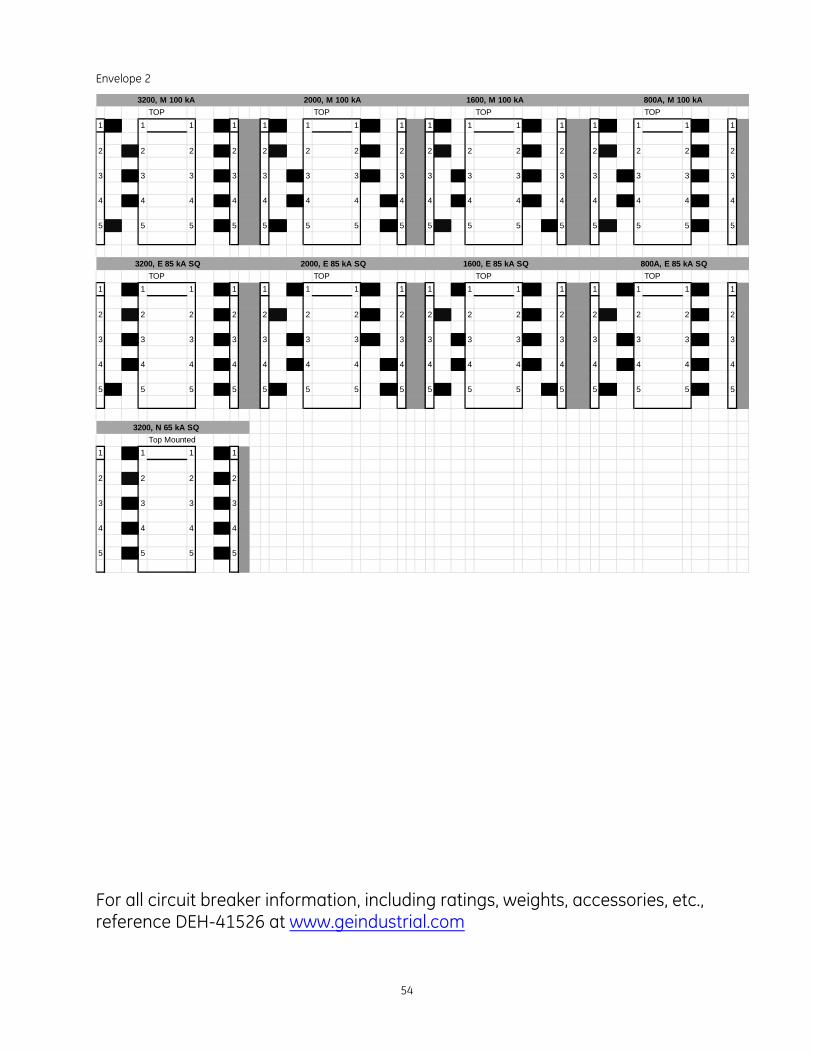
54
Envelope 2
For all circuit breaker information, including ratings, weights, accessories, etc., reference DEH-41526 at www.geindustrial.com
TOP TOP TOP TOP
1 1 1 1 1 1 1 1 1 1 1 1 1 1 1 1
2 2 2 2 2 2 2 2 2 2 2 2 2 2 2 2
3 3 3 3 3 3 3 3 3 3 3 3 3 3 3 3
4 4 4 4 4 4 4 4 4 4 4 4 4 4 4 4
5 5 5 5 5 5 5 5 5 5 5 5 5 5 5 5
TOP TOP TOP TOP
1 1 1 1 1 1 1 1 1 1 1 1 1 1 1 1
2 2 2 2 2 2 2 2 2 2 2 2 2 2 2 2
3 3 3 3 3 3 3 3 3 3 3 3 3 3 3 3
4 4 4 4 4 4 4 4 4 4 4 4 4 4 4 4
5 5 5 5 5 5 5 5 5 5 5 5 5 5 5 5
Top Mounted
1 1 1 1
2 2 2 2
3 3 3 3
4 4 4 4
5 5 5 5
3200, N 65 kA SQ
3200, M 100 kA 2000, M 100 kA 1600, M 100 kA 800A, M 100 kA
3200, E 85 kA SQ 2000, E 85 kA SQ 1600, E 85 kA SQ 800A, E 85 kA SQ

55

56
General Electric Company 41 Woodford Avenue Plainville, CT 06062 U.S.A. DEH-537 2012 General Electric Company