envisat-asar main menu - esa earth observation … · 1 envisat-asar main menu ... • h/a/alpha...
TRANSCRIPT

EARTH OBSERVATION
AIRBORNE SENSORS
1

CONTENTS
1 ENVISAT-ASAR Main Menu ........................................................................................... 3
1.1 Hierarchical Software Structure ................................................................................. 5 2 ENVIRONNEMENT ......................................................................................................... 7 3 IMPORT........................................................................................................................... 10
3.1 Input Data File AIRSAR.......................................................................................... 11 3.2 Input Data File CONVAIR ...................................................................................... 13 3.3 Input Data File EMISAR.......................................................................................... 15 3.4 Input Data File ESAR .............................................................................................. 17 3.5 Input Data File PISAR ............................................................................................. 19 3.6 Input Data File RAMSES......................................................................................... 21 3.7 Extract – Full Resolution.......................................................................................... 23 3.8 Extract – Sub Area ................................................................................................... 25
4 PROCESS......................................................................................................................... 27 4.1 Process [T3] Elements............................................................................................. 28 4.2 Process – Batch Procedure ...................................................................................... 31
5 DISPLAY ......................................................................................................................... 35 6 TOOLS ............................................................................................................................. 36
2

1 ENVISAT-ASAR MAIN MENU
E.O. - AIRBORNE SENSORS
Description: This EO Scientific Investigator - Airborne Sensors specific interface is designed to help and guide an EO investigator to process Fully Polarimetric data along a recommended processing chain summarizing essential functionalities.
The EO Scientific Investigator - Airborne Sensors interface proposes the following different main functions: Environnement This menu permits to set Main Variables and to configure the
Processing Environnement. Import This menu may be used to import and convert the different
Airborne Sensors fully polarimetric data to complex 3x3 Coherency raw binary data. It offers QuickLook and Sub-Area Extraction functionalities.
Process This menu proposes a basic processing approach based on some essential polarimetric functionalities to provide a first qualitative analysis of the fully polarimetric data set processed. Theses different processing functions are proposed in the form of one batch processing, covering:
• Speckle Filter (Box Car, J.S. Lee Refined Filter) • H/A/Alpha Decomposition and Analysis • Unsupervised Wishart H/A/Alpha Classification
3

Display This menu proposes to create and export 8-bit or 24-bit dynamic range images, written in the common Windows Bitmap and TIFF formats. It is also possible to call the PolSARpro Viewer software to display the resulting images.
Tools This menu proposes different Directory and File management tools.
Loads the HTML Frames Editor to dynamically display the PolSARpro Help files.
Launches the PolSARpro BMP Viewer.
Exit Closes the EO Scientific Investigator - Airborne Sensors menu to come back to the PolSARpro Main Menu.
4

1.1 HIERARCHICAL SOFTWARE STRUCTURE
ENVIRONNEMENT
IMPORT Input Data File
Header Analysis
Quicklook
Extract Full Resolution
Sub-Area
PROCESS [T3] Elements
EO Scientific Investigator
MEN
U
Batch Process
[ S2 ]
[ T3 ] Create BMP File
Create RGB File
Create HSL File
[ T4 ]
[ C2 ]
[ C3 ]
[ C4 ]
(Sxx, Sxy)
(Ixx, Ixy)
DISPLA
Y
View BMP File
[ S2 ]
[ T3 ] IEEE Convert
Sub Data Extraction
Rotation 90 right
Rotation 90 left
Rotation 180
Flip Up-Down
Flip Left-Right
Transpose
[ T4 ]
[ C2 ]
[ C3 ]
[ C4 ]
(Sxx, Sxy)
(Ixx, Ixy)
Data File Management Copy File
Delete File
Rename File
Create Directory
Copy Directory
TOO
LS
Delete Directory
5

Rename Directory
Export ENVI Data Format
RAT Data Format
My Function Create
Delete
Execute
6

2 ENVIRONNEMENT
Environnement
Description:
This Tcl-Tk Application sets and configures the Main Variables of the Processing Environnement
Comments:
Blue Parameters may be modified using the widget buttons : , or . Input/Output Arguments:
Main Input Directory
Configure the single data set Main Directory location. This variable is then provided as an argument to most of the data processing programs.
Automatic Data Check
To improve the software quality, this parameter validates the detection and correction of any abnormal binary input value like Null or NaN values.
ENVI Config File
Enables the creation of binary data accompanying files, used to associate to each output binary data file of a configuration file, useful to export binary data to GIS software like ENVI.
Run Trace This function enables a specific Tcl-Tk widget window providing operational and informative error messages. This window enables
7

any troubleshooting by printing a backtrace with each warning or error message (equivalent to the Unix command: troff). This should help track down the cause of any error.
Display Size This function is used to set the Image Screen Display Size, using
the widget buttons : or . ColorMaps This function is used to edit and modify the different Color
Palettes. These colormaps are used to code the different data process bitmap output files.
Supervised Colormap16: corresponds to the colormap used during a Wishart Supervised classification. The associated file is: PolSARpro/ColorMap/supervised_colormap16.pal
Unsupervised Colormap9: corresponds to the colormap used during the H/A/Alpha planes unsupervised classification. The associated file is: PolSARpro/ColorMap/planes_H_A_Alpha_colormap9.pal
8

Unsupervised Colormap8: corresponds to the colormap used during the H/Alpha
Wishart unsupervised classification. The associated file is: PolSARpro/ColorMap/Wishart_colormap8.pal
Unsupervised Colormap16: corresponds to the colormap used during the H/A/Alpha Wishart unsupervised classification. The associated file is: PolSARpro/ColorMap/Wishart_colormap16.pal
Trace Messages:
Open Window Environnement Close Window Environnement
9

3 IMPORT IMPORT Aim: This menu may be used to import and convert the different Airborne Sensors (AIRSAR, Convair, EMISAR, ESAR, PISAR, RAMSES) fully polarimetric data to complex 3x3 Coherency raw binary data. Hierarchical Structure:
IMPORT Input Data File
Quicklook
Extract Full Resolution
Sub-Area
EO Scientific Investigator
MEN
U
10

3.1 INPUT DATA FILE AIRSAR
AIRSAR Input Data File
Description:
This program converts polarimetric data sets encoded using the AIRSAR STK specific data format to PolSARpro compatible binary data. The resulting polarimetric data are represented under the form of a (3*3) Complex Coherency matrix [T3].
Comments: Blue Parameters may be modified using the widget button : . Red Parameters can be modified from keyboard or using the widget button : .
Input/Output Arguments: Input Directory
Indicates the location of the considered Main Directory (MD) containing the AIRSAR data file to be converted.
Output Directory
Indicates the location of the converted data output directory. The default value is set to the Main Directory / T3.
AIRSAR Input Data File
Corresponds to the input AIRSAR STK format data file to be processed. The denomination STK stands for Input Stokes Compressed File and comes from the fact that AIRSAR data consist of elements of the polarimetric Stokes matrix processed through a compression algorithm
Initial Number of Rows/Columns: Input Stokes data files may, or not, contain a header block describing some of the polarimetric data characteristics and particularly the number of rows and columns.
• If the input file contains a header, users have to select the header mode by ticking the Header Option. . • If the input file does not contain a header, users have to provide the
11

considered image Initial Number of Rows and Columns.
Trace Messages:
Open Window AIRSAR Input File Process The Function Soft/data_import/airsar_header.exe Check RunTime Errors OK Close Window AIRSAR Input File
12
3.2 INPUT DATA FILE CONVAIR
CONVAIR Input Data File
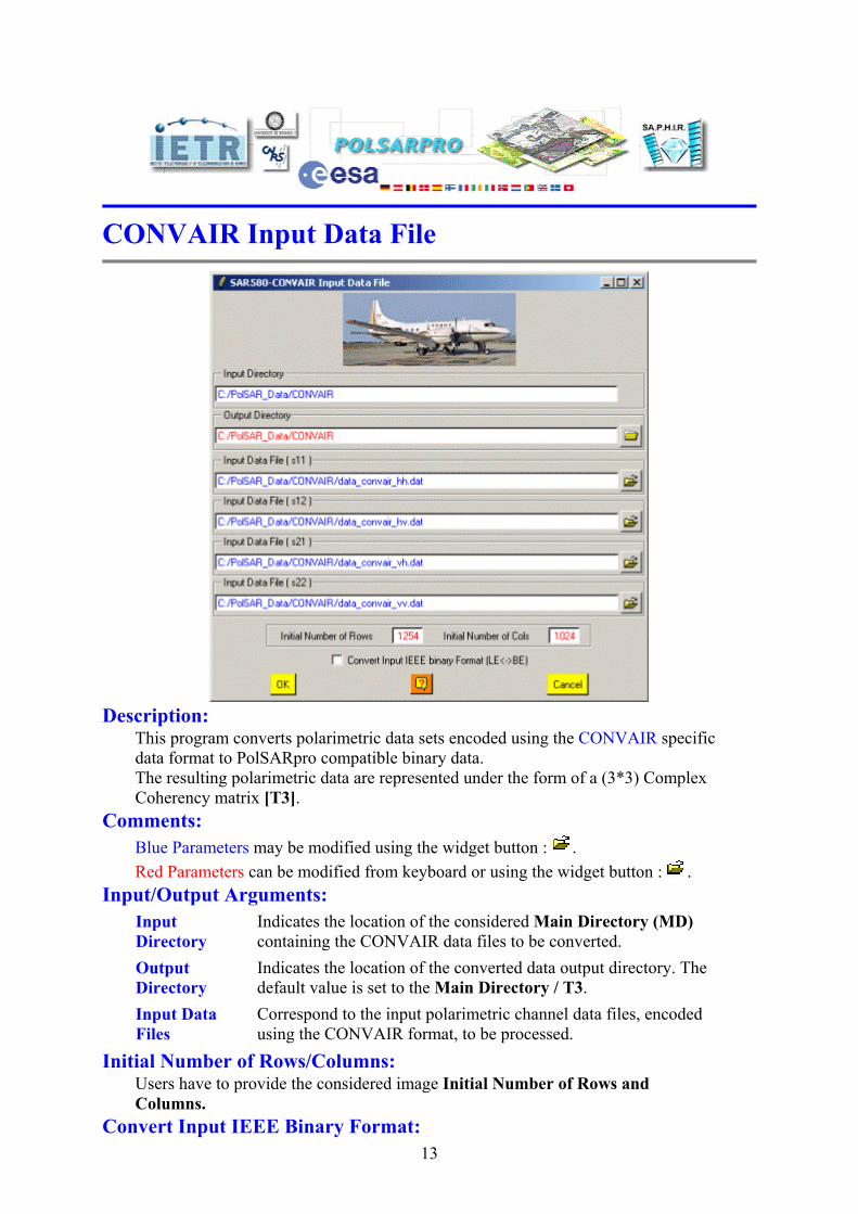
Description:
This program converts polarimetric data sets encoded using the CONVAIR specific data format to PolSARpro compatible binary data. The resulting polarimetric data are represented under the form of a (3*3) Complex Coherency matrix [T3].
Comments: Blue Parameters may be modified using the widget button : . Red Parameters can be modified from keyboard or using the widget button : .
Input/Output Arguments: Input Directory
Indicates the location of the considered Main Directory (MD) containing the CONVAIR data files to be converted.
Output Directory
Indicates the location of the converted data output directory. The default value is set to the Main Directory / T3.
Input Data Files
Correspond to the input polarimetric channel data files, encoded using the CONVAIR format, to be processed.
Initial Number of Rows/Columns: Users have to provide the considered image Initial Number of Rows and Columns.
Convert Input IEEE Binary Format: 13

Binary data may be encoded according to the IEEE Little Endian or Big Endian convention according to the type of architecture or operating system of the computer used to process SAR data. By ticking the appropriate box, users may indicate PolSARpro to toggle between these two binary formats before converting the polarimetric data files.
Trace Messages: Open Window CONVAIR Input File Close Window CONVAIR Input File
14

3.3 INPUT DATA FILE EMISAR
EMISAR Input Data File
Description:
This program converts polarimetric data sets encoded using the EMISAR specific data format to PolSARpro compatible binary data. The resulting polarimetric data are represented under the form of a (3*3) Complex Coherency matrix [T3].
Comments: Blue Parameters may be modified using the widget button : . Red Parameters can be modified from keyboard or using the widget button : .
Input/Output Arguments: Input Directory
Indicates the location of the considered Main Directory (MD) containing the CONVAIR data files to be converted.
Output Directory
Indicates the location of the converted data output directory. The default value is set to the Main Directory / T3.
15

Data Format Correspond to the EMISAR encoded data format used. By ticking the appropriate box, users may indicate PolSARpro to toggle between these two binary data formats before converting the polarimetric data files.
Input Data Files
Correspond to the input polarimetric channel data files, encoded using the EMISAR format, to be processed.
Initial Number of Rows/Columns: Users have to provide the considered image Initial Number of Rows and Columns.
Convert Input IEEE Binary Format: Binary data may be encoded according to the IEEE Little Endian or Big Endian convention according to the type of architecture or operating system of the computer used to process SAR data. By ticking the appropriate box, users may indicate PolSARpro to toggle between these two binary formats before converting the polarimetric data files.
Trace Messages: Open Window EMISAR Input File Close Window EMISAR Input File
16

3.4 INPUT DATA FILE ESAR
ESAR Input Data File
Description:
This program converts polarimetric data sets encoded using the ESAR specific data format to PolSARpro compatible binary data. The resulting polarimetric data are represented under the form of a (3*3) Complex Coherency matrix [T3].
Comments: Blue Parameters may be modified using the widget button : . Red Parameters can be modified from keyboard or using the widget button : .
Input/Output Arguments: Input Directory
Indicates the location of the considered Main Directory (MD) containing the ESAR data files to be converted.
Output Directory
Indicates the location of the converted data output directory. The default value is set to the Main Directory / T3.
Input Data Files
Correspond to the input polarimetric channel data files, encoded using the ESAR format, to be processed.
Initial Number of Rows/Columns: Input ESAR data files may, or not, contain a header block describing some of the polarimetric data characteristics and particularly the number of rows and columns.
17

• If the input file contains a header, users have to select the header mode by ticking the Header Option. . • If the input file does not contain a header, users have to provide the considered image Initial Number of Rows and Columns.
Convert Input IEEE Binary Format: Binary data may be encoded according to the IEEE Little Endian or Big Endian convention according to the type of architecture or operating system of the computer used to process SAR data. By ticking the appropriate box, users may indicate PolSARpro to toggle between these two binary formats before converting the polarimetric data files.
Trace Messages: Open Window ESAR Input File Process The Function Soft/data_import/esar_header.exe Check RunTime Errors OK Close Window ESAR Input File
18

3.5 INPUT DATA FILE PISAR
PISAR Input Data File
Description:
This program converts polarimetric data sets encoded using the PISAR specific data format to PolSARpro compatible binary data. The resulting polarimetric data are represented under the form of a (3*3) Complex Coherency matrix [T3].
Comments: Blue Parameters may be modified using the widget button : . Red Parameters can be modified from keyboard or using the widget button : .
Input/Output Arguments: Input Directory
Indicates the location of the considered Main Directory (MD) containing the CONVAIR data files to be converted.
Output Directory
Indicates the location of the converted data output directory. The default value is set to the Main Directory / T3.
Data Format Correspond to the PISAR encoded data format used. By ticking the 19

appropriate box, users may indicate PolSARpro to toggle between these two binary data formats before converting the polarimetric data files.
Input Data Files
Correspond to the input polarimetric channel data files, encoded using the PISAR format, to be processed.
Convert Input IEEE Binary Format: Binary data may be encoded according to the IEEE Little Endian or Big Endian convention according to the type of architecture or operating system of the computer used to process SAR data. By ticking the appropriate box, users may indicate PolSARpro to toggle between these two binary formats before converting the polarimetric data files.
Trace Messages: Open Window PISAR Input File Process The Function Soft/data_import/pisar_header.exe Check RunTime Errors OK Close Window PISAR Input File
20

3.6 INPUT DATA FILE RAMSES
RAMSES Input Data File
Description:
This program converts polarimetric data sets encoded using the RAMSES specific data format to PolSARpro compatible binary data. The resulting polarimetric data are represented under the form of a (3*3) Complex Coherency matrix [T3].
Comments: Blue Parameters may be modified using the widget button : . Red Parameters can be modified from keyboard or using the widget button : .
Input/Output Arguments: Input Directory
Indicates the location of the considered Main Directory (MD) containing the RAMSES data files to be converted.
Output Directory
Indicates the location of the converted data output directory. The default value is set to the Main Directory / T3.
Input Data Files
Correspond to the input polarimetric channel data files, encoded using the RAMSES format, to be processed.
Initial Number of Rows/Columns: Users have to provide the considered image Initial Number of Rows and Columns.
Convert Input IEEE Binary Format: 21

Binary data may be encoded according to the IEEE Little Endian or Big Endian convention according to the type of architecture or operating system of the computer used to process SAR data. By ticking the appropriate box, users may indicate PolSARpro to toggle between these two binary formats before converting the polarimetric data files.
Trace Messages: Open Window RAMSES Input File Close Window RAMSES Input File
22

3.7 EXTRACT – FULL RESOLUTION
E.O. - Airborne Sensors Extract Data
Description:
This Application is used to import and convert the different Airborne Sensors (AIRSAR, CONVAIR, EMISAR, ESAR, PISAR, RAMSES) fully polarimetric data to complex (3x3) Coherency raw binary data. It is possible to extract the full image or a sub-part of it, and to apply or not a sub-sampling or multilooking operation.
Comments: Blue Parameters may be modified using the widget button : . Red Parameters can be modified from keyboard.
Input/Output Arguments: Input Directory
Indicates the location of the considered Main Directory (MD) containing the data files to be converted.
Output Directory Indicates the location of the converted data output directory.
Output Image Number of Rows/Columns: The output image numbers of rows and columns are initialised to the input data set dimensions. Users wishing to process a sub-part of the initial image can modify the Init and End values of the converted images rows and columns. Note: init and end values have to remain within the range defined by the input image
23

dimensions. Processing Parameters:
Full Resolution This is the default selection. This corresponds to a one-to-one conversion without applying any data processing. The extracted image has the same format than the source data.
Sub Sampling This selection offers the possibility to perform a sub-sampling operation during the conversion of the polarimetric data files.
Multi Look This selection offers the possibility to perform an incoherent multilooking operation during the conversion of the polarimetric data files.
Trace Messages: Open Window EOSI Extract Data Process The Function Soft/data_import/NameOfTheSensor_convert_T3.exe or Process The Function Soft/data_import/NameOfTheSensor_convert_MLK_T3.exeCheck RunTime Errors OK Close Window EOSI Extract Data
24

3.8 EXTRACT – SUB AREA
E.O. - Airborne Sensors Sub Area Extract Data
Description: This Application is used to import and convert the different Airborne Sensors (AIRSAR, CONVAIR, EMISAR, ESAR, PISAR, RAMSES) fully polarimetric data to complex (3x3) Coherency raw binary data. The area of interest (AOI) to be extracted is selected from a quick look image.
Extracted areas may be defined by the way of a graphic interface which permits to delimitate areas by defining regions of interest on a visual representation of the data to be extracted.
The Sub Area Graphics Editor proposes the following different functionnalities:
• 1 : Mouse Pointer Position. • 2 : Coordinates of two diagonally opposite corners of the selected area. • .....(x1,y1) = Upper-Left corner and (x2,y2) = Lower-Right corner. • 3 : Number of Columns and Rows of the selected area. • 4 : Clear the selected area and reset the coordinates values. • 5 : Zoom Values: Initial QuickLook Image Zoom value (left) • .....Actual BMP Image Zoom value (right). Cumulative Zoom Value (center). • 6 : Select the Zoom function. • .....To Zoom-In, left-click the image. To Zoom-Out, right-click the image. • 7 : Launch the extraction procedure. • 8 : Select the rectangular selection of Area of Interest (AoI). • 9 : Select the full image.
25

• 10 : Toggle selected area contour color (black / white).
Trace Messages:
Open Window Sub Area Graphic Editor Close Window Sub Area Graphic Editor Open Window EOSI Extract Data Process The Function Soft/data_import/NameOfTheSensor_convert_T3.exe or Process The Function Soft/data_import/NameOfTheSensor_convert_MLK_T3.exeCheck RunTime Errors OK Close Window EOSI Extract Data
26

4 PROCESS PROCESS Aim: This menu proposes a basic processing approach based on some essential polarimetric functionalities to provide a first qualitative analysis of the fully polarimetric data set processed. Theses different processing functions are proposed in the form of one batch processing, covering:
• Speckle Filter (BoxCar, JS Lee refined filter) • H / A / α Decomposition and analysis • Unsupervised Wishart - H / A / α Classification
Hierarchical Structure:
PROCESS [T3] Elements
Batch Process
EO Scientific Investigator
MEN
U
27

4.1 PROCESS [T3] ELEMENTS
Coherency [T3] matrix Elements Processing
Description:
Creates binary files corresponding to the modulus and argument of the (3x3) complex Coherency matrix ([T3]) raw binary data. An option may be set to simultaneously create the corresponding bitmap image files.
A (3x3) Coherency [T3] matrix is an incoherent polarimetric representation relating to second order statistics of the polarimetric scattering matrix elements. This matrix is hermitian semi-definite positive. Coherency matrix binary data files have to be located in the MainDirectory / T3 (MD / T3) directory and described by a text configuration file. The contents of the MainDirectory / T3 (MD / T3) must be the following: • MD / T3 /.
• MD / T3 / config.txt • MD / T3 / T11.bin • MD / T3 / T12_real.bin • MD / T3 / T12_imag.bin • MD / T3 / T13_real.bin • MD / T3 / T13_imag.bin • MD / T3 / T22.bin
28

• MD / T3 / T23_real.bin • MD / T3 / T23_imag.bin • MD / T3 / T33.bin
Note: Txy_real.bin and Txy_imag.bin denote respectively real and imaginary parts of a coherency matrix complex element.
Comments: Blue Parameters may be modified using the widget button : . Red Parameters can be modified from keyboard.
Input/Output Arguments: Input Directory
Indicates the complete location of the considered MainDirectory / T3 (MD / T3) containing the [T3] matrix data to be processed.
Output Directory
Indicates the location of the processed data output directory. The default value is set automatically to the MainDirectory / T3 (MD / T3).
Output Image Number of Rows/Columns: The output image numbers of rows and columns are initialised to the input data set dimensions. Users wishing to process a sub-part of the initial image can modify the Init and End values of the converted images rows and columns. Note: init and end values have to remain within the range defined by the input image dimensions.
Selection of the Channels to be Processed: Several channels may be processed at a time. The selection of the BMP options enables the creation of output bmp files. Users may choose between three types of output binary data :
• Modulus : Linear representation of the considered [T3] element amplitude. Ouput file name : Tij_mod.bin (.bmp) • Modulus : Element amplitude in dB=10log10(Modulus). Ouput file name : Tij_dB.bin (.bmp) • Phase : Argument of the considered complex [T3] element (Only available for off-diagonal elements). Ouput file name : Tij_pha.bin (.bmp)
• Span : Correspond to the sum of the diagonal elements of [T3], may also be processed (linear and dB) using this program.
Trace Messages: Open Window Coherency Elements T3 Process The Function Soft/data_process/sngl/process_T3_T4.exe Check RunTime Errors OK if selected: Process The Function Soft/data_process/sngl/process_span.exe if selected: Process The Function Soft/bmp_process/create_BMP_File.exe Check RunTime Errors OK Close Window Coherency Elements T3
29

30

4.2 PROCESS – BATCH PROCEDURE
Coherency [T3] Data Batch Procedure
Description:
This function is used to apply sequentially different polarimetric data processes. The different steps of this batch process are:
• Speckle Filter (BoxCar, JS Lee refined filter) • H / A / Alpha Decomposition and analysis • Unsupervised Wishart - H / A / Alpha Classification
This basic processing approach provides a first qualitative analysis of the fully polarimetric data set processed.
Comments: Blue Parameters may be modified using the widget button : . Red Parameters can be modified from keyboard.
Input/Output Arguments: Input Directory
Indicates the location of the considered Main Directory / T3 (MD/T3) containing the polarimetric data sets to be filtered.
Output Directory Indicates the location of the data output directory.
Output Image Number of Rows/Columns: The output image numbers of rows and columns are initialised to the input data set dimensions.
31

Users wishing to process a sub-part of the initial image can modify the Init and End values of the converted images rows and columns. Note: init and end values have to remain within the range defined by the input image dimensions.
Speckle Filter: This function is used to apply a Polarimetric Speckle filtering on (3x3) Coherency matrix ([T3]) raw binary data format. Two Polarimetric Speckle Filters are proposedBox Car Filter This function filters [T3] matrix polarimetric raw binary data sets
using a Boxcar filter which performs incoherent averaging within a (N*N) sliding window (W). Filtering Parameters • Window Size: Users have to set the size of the (N*N) sliding window used to compute the local estimate of the average matrix. The default value of N is set to 7. Note : The default value of the Output Directory is set automatically to : Main Directory_BOX / T3.
Input Directory • MD/T3/. • MD/T3/config.txt • MD/T3/T11.bin • MD/T3/T12_real.bin • MD/T3/T12_imag.bin • MD/T3/T13_real.bin • MD/T3/T13_imag.bin • MD/T3/T22.bin • MD/T3/T23_real.bin • MD/T3/T23_imag.bin • MD/T3/T33.bin
Filter
Output Directory MD_BOX/T3 • MD_BOX/T3/. • MD_BOX/T3/config.txt • MD_BOX/T3/T11.bin • MD_BOX/T3/T12_real.bin • MD_BOX/T3/T12_imag.bin • MD_BOX/T3/T13_real.bin • MD_BOX/T3/T13_imag.bin • MD_BOX/T3/T22.bin • MD_BOX/T3/T23_real.bin • MD_BOX/T3/T23_imag.bin • MD_BOX/T3/T33.bin
J.S. Lee Refined Filter
This function filters [T3] matrix polarimetric raw binary data sets using the J.S. Lee refined filter which estimates local statistics within a (N*N) sliding window (W) and filters data in an adaptive way by minimizing a least square constraint. This refined approach also includes the use of directional masks for the local statistics estimation. Filtering Parameters • Number of Looks: Users have to set the Input data equivalent number of looks used to compute the a priori input speckle noise variance. The default value of N is set to 1. • Window Size: Users have to set the size of the (N*N) sliding window used to compute the local estimate of the average matrix. The default value of N is set to 7. Note : The default value of the Output Directory is set automatically to : Main Directory_LEE / T3.
Input Directory • MD/T3/. • MD/T3/config.txt • MD/T3/T11.bin • MD/T3/T12_real.bin
Filter
Output Directory MD_LEE/T3 • MD_LEE/T3/. • MD_LEE/T3/config.txt • MD_LEE/T3/T11.bin • MD_LEE/T3/T12_real.bin
32

• MD/T3/T12_imag.bin • MD/T3/T13_real.bin • MD/T3/T13_imag.bin • MD/T3/T22.bin • MD/T3/T23_real.bin • MD/T3/T23_imag.bin • MD/T3/T33.bin
• MD_LEE/T3/T12_imag.bin • MD_LEE/T3/T13_real.bin • MD_LEE/T3/T13_imag.bin • MD_LEE/T3/T22.bin • MD_LEE/T3/T23_real.bin • MD_LEE/T3/T23_imag.bin • MD_LEE/T3/T33.bin
H/A/Alpha Decomposition: This program creates binary files corresponding to the different polarimetric descriptors obtained from the H/A/Alpha decomposition of [T3] matrix image. The H/A/Alpha polarimetric decomposition is based on an eigenvector decomposition of the (3x3) coherency [T3] matrix. An option may be set to simultaneously create the corresponding bitmap image files. Processing Parameters
Data to be decomposed may be processed through an additional filtering procedure consisting of a boxcar filter. Users have then to set the size of the (N*N) sliding window used to compute the local estimate of the average matrix. The default value of N is set to 0. Users wishing to avoid additional filtering may set N to 1.
Unsupervised Wishart - H/A/Alpha Classification: This program creates binary and bitmap image files resulting from the segmentation of polarimetric data using the Wishart H-Alpha and Wishart H-A-Alpha schemes.
33
Output Files Each classification procedures creates ouput binary files and the corresponding optional bitmap image files.
• wishart_H_alpha_class_x.bin (.bmp) • wishart_H_A_alpha_class_x.bin (.bmp)
The variable x indicates the window size of the eventual additional filtering performed prior to data classification.
Processing Parameters
Data to be decomposed may be processed through an additional filtering procedure consisting of a boxcar filter. Users have then to set the size of the (N*N) sliding window used to compute the local estimate of the average matrix. The default value of N is set to 0. Users wishing to avoid additional filtering may set N to 1.
The segmentation termination criterion consists of a logical combination of two conditions.The iterative k-mean clustering procedure is stopped if :
• A sufficiently low percentage of pixels switch class from one iteration to the other. • The number of iterations reaches a maximum value
Numerical values are automatically set to default values and may be modified.
ColorMaps The color coding of the bitmap output files is realized by the way of a 8 or 16 element colormap initialised with arbitrary values. Users have the possibility to modify the elements of the colormaps in an interactive way.

Trace Messages: Open Window Batch Procedure T3 if selected: Process The Function Soft/speckle_filter/boxcar_filter_T3.exe or Process The Function Soft/speckle_filter/lee_refined_filter_T3.exe Check RunTime Errors OK if selected: Process The Function Soft/data_process/sngl/h_a_alpha_decomposition_T3.exe ___if selected: Process The Function Soft/data_process/sngl/h_a_alpha_planes_classifier.exe Check RunTime Errors OK if selected: Process The Function Soft/data_process/sngl/wishart_h_a_alpha_classifier.exe Process The Function Soft/bmp_process/create_BMP_file.exe Check RunTime Errors OK Close Window Batch Procedure T3
34

5 DISPLAY DISPLAY Aim: This menu proposes to create, display and export 8-bit or 24-bit dynamic range images, written in the common Windows Bitmap format. It is also possible to call the PolSARpro Viewer software to display the resulting images. Hierarchical Structure:
[ S2 ]
[ T3 ] Create BMP File
Create RGB File
Create HSL File
[ T4 ]
[ C2 ]
[ C3 ]
[ C4 ]
(Sxx, Sxy)
(Ixx, Ixy)
DISPLA
Y
View BMP File
Note : In the ENVISAT / ASAR Spaceborne Data Processing Version package software case, only the (Ixx, Ixy) Display button is enable, allowing thus only the Intensity raw binary data display functionalities available. A complete description of all the Display functionalities is given in the PolSARpro Display & Viewer 3.0 Help Document.
35

6 TOOLS TOOLS Aim: This menu proposes different Directory and File management tools. Hierarchical Structure:
[ S2 ]
[ T3 ] IEEE Convert
Sub Data Extraction
Rotation 90 right
Rotation 90 left
Rotation 180
Flip Up-Down
Flip Left-Right
Transpose
[ T4 ]
[ C2 ]
[ C3 ]
[ C4 ]
(Sxx, Sxy)
(Ixx, Ixy)
Data File Management Copy File
Delete File
Rename File
Create Directory
Copy Directory
Delete Directory
Rename Directory
Export ENVI Data Format
RAT Data Format
My Function Create
Delete
TOO
LS
Execute
36

Note : In the ENVISAT / ASAR Spaceborne Data Processing Version package software case, only the (Ixx, Ixy) Tools button is enable, allowing thus only the Intensity raw binary Data File Transformation functionalities available. A complete description of all the Tools functionalities is given in the PolSARpro Tools Help Document.
37