eosdis maintenance & development (emd) project ... internal work products 4-5 4.3.3 acquired...
TRANSCRIPT
RAYTHEON COMPANY
ERRATA NOTICE EOSDIS Maintenance & Development (EMD) Project
Contract No. NAS5-03098
April 2, 2004
Document No.: 110-EMD-001
Title: Configuration Management Plan for the EMD Project
Enclosed please find change pages for the subject document. Please replace the pages as follows:
Remove Insert
Cover Cover
5-5 and 5-6 5-5 and 5-6
If you have any questions, please contact our Data Management Office at (301) 925-0512.

110-EMD-001
EOSDIS Maintenance and Development Project
Configuration Management Plan for the EMD Project
October 2003
Raytheon Company Upper Marlboro, Maryland

Configuration Management Plan for the EMD Project
October 2003
Prepared Under Contract NAS5-03098 CDRL Item #019
RESPONSIBLE AUTHOR
Steve Haupt /s/ 10/31/2003
Steve Haupt, Configuration Management Date ECS Maintenance and Development Project
RESPONSIBLE OFFICE
Carolyn Whitaker /s/ 10/31/2003
Carolyn Whitaker, Configuration Management Manager Date ECS Maintenance and Development Project
Raytheon Company Upper Marlboro, Maryland
110-EMD-001

This page intentionally left blank.
110-EMD-001

Preface
This document is a formal contract deliverable. It requires Government review and approval within 20 business days. Changes to this document will be made by document change notice(DCN) or by complete revision.
Any questions should be addressed to:
Data Management Office The EMD Project Office Raytheon Company 1616 McCormick Drive Upper Marlboro, Maryland 20774-5301
Revision History
Document Number Status/Issue Publication Date CCR Number
110-EMD-001 Revision - October 2003 03-0733
iii 110-EMD-001

This page intentionally left blank.
iv 110-EMD-001

Abstract
This document defines the Contractor’s configuration management organization, and the activities to be followed in baseline identification and baseline change control. This plan provides the relationship between the Government and Contractor Configuration Control Boards, change control procedures for processing change requests and approving baselines. It contains sections for each of the major activities to be defined and controlled by configuration management. This plan also describes the tools to be used in administering baseline changes, as well as version control methods.
Keywords: EOSDIS, EMD, Configuration-Management, Change Control Board, Baseline
v 110-EMD-001

This page intentionally left blank.
vi 110-EMD-001

Contents
Preface
Abstract
1. Introduction
1.1 Document Identification.................................................................................................1-1
1.2 Scope and Purpose..........................................................................................................1-1
1.3 Status ..............................................................................................................................1-1
1.4 Document Organization .................................................................................................1-1
1.5 Order of Precedence .......................................................................................................1-1
2. Related Documentation
2.1 Parent Documents...........................................................................................................2-1
2.2 Applicable Documents ...................................................................................................2-1
3. Organization
3.1 Organization Structure ...................................................................................................3-1
3.2 Internal CM Forms .........................................................................................................3-3
3.3 Process Metrics...............................................................................................................3-3
4. Configuration Identification
4.1 Top-Level Document Tree .............................................................................................4-2
4.2 Numbering Conventions ................................................................................................4-5
4.3 Configuration Baselines .................................................................................................4-5
4.3.1 Deliverable Products ..........................................................................................4-5
vii 110-EMD-001
4.3.2 Internal Work Products ......................................................................................4-5
4.3.3 Acquired Products ..............................................................................................4-6
5. Configuration Control
5.1 Configuration Management Objectives..........................................................................5-1
5.2 Configuration Control Boards ........................................................................................5-1
5.2.1 ESDIS CCB........................................................................................................5-2
5.2.2 EMD CCB..........................................................................................................5-2
5.2.3 EDF (Infrastructure) CCB..................................................................................5-3
5.2.4 SCDV CCB ........................................................................................................5-3
5.3 Management, Processing, and Administration of MRs and CCRs ................................5-4
5.3.1 Configuration Change Requests.........................................................................5-4
5.3.2 CCB Proceedings ...............................................................................................5-5
5.3.3 Request for Deviation or Waiver........................................................................5-6
5.3.4 Implementation of CCB Direction ....................................................................5-6
5.3.5 Configuration Change Documentation...............................................................5-6
5.3.6 Configuration Control Support Activities ..........................................................5-7
5.3.7 Configuration Problem Management .................................................................5-8
5.3.8 Configuration Change Adjudication ..................................................................5-8
5.3.9 Development, Deployment and Installation of Changes....................................5-9
5.4 DAAC Unique Extensions (DUEs)................................................................................5-9
5.5 Software Configuration Management ............................................................................5-9
5.5.1 Event Driven Processes .................................................................................... 5-12
5.5.2 Automated and Real Time Processes ............................................................... 5-14
5.6 Software Configuration Management Tools ................................................................ 5-15
5.6.1 Remedy™ Trouble Ticketing........................................................................... 5-16
5.6.2 Distributed Defect Tracking System (DDTS™) .............................................. 5-16
5.6.3 Software Turnover Tracking System (STTS) .................................................. 5-16
5.6.4 ClearCase™ Software Configuration Management System (ClearCase™) .... 5-16
5.6.5 ClearCase™ Support Scripts............................................................................ 5-17
5.6.6 ClearCase™ Baseline Manager (BLM) ........................................................... 5-17
5.6.7 Configuration Data Management Tracking System (CDMTS) ....................... 5-18
5.6.8 EMD Change Manager (ECM) ........................................................................ 5-18
viii 110-EMD-001

5.6.9 ClearCase™ Delivery Tool .............................................................................. 5-19
5.6.10 Engineering Software Delivery Daemon.......................................................... 5-19
5.6.11 Source Code Delivery Tool.............................................................................. 5-19
5.6.12 Custom Code Installation Emulator ................................................................. 5-19
5.7 EMD Baseline Information System (EBIS) ................................................................. 5-19
5.8 Library Maintenance .................................................................................................... 5-22
5.8.1 COTS Software Library ................................................................................... 5-22
6. Configuration Status Accounting (CSA)
6.1 Configuration Status Reports .........................................................................................6-1
6.2 To Be Resolved (TBR) / To Be Determined (TBD) Reports.........................................6-1
6.3 As-Built Records Format, Content, and Process............................................................6-1
7. Configuration Audits
7.1 Process Audits ................................................................................................................7-1
7.2 Physical Configuration Audits .......................................................................................7-1
7.2.1 Software PCA.....................................................................................................7-1
7.2.2 Hardware PCA ...................................................................................................7-3
7.3 Functional Configuration Audits....................................................................................7-3
7.4 Audit Reports .................................................................................................................7-3
8. Data Management
8.1 Data Management Organization.....................................................................................8-1
8.2 Data Management Goals and Objectives .......................................................................8-1
8.3 Data Management Responsibilities ................................................................................8-1
8.3.1 Identifying Data Requirements ..........................................................................8-1
8.3.2 Document Numbering ........................................................................................8-2
8.3.3 Document Generation and Internal Review .......................................................8-2
8.3.4 Document Submittal and Release.......................................................................8-2
8.3.5 Document Archiving ..........................................................................................8-4
8.3.6 Status Reporting .................................................................................................8-4
ix 110-EMD-001

List of Figures
3.1-1. EMD Organization..........................................................................................................3-1
3.1-2. CM and DM Organizations.............................................................................................3-3
5.2-1. Configuration Control Boards.........................................................................................5-2
5.3.6.1-1. ROM Impact Analyses..............................................................................................5-7
5.5-1. SCM Tools Overview for Custom Software................................................................ 5-11
5.6.3-1. Custom Code Baseline Management ......................................................................... 5-17
5.7-1. EMD Baseline Information System (EBIS).................................................................. 5-21
7.2.1-1. COTS Software Discrepancy Report ...........................................................................7-2
7.4-1. COTS Software Site Audit Report..................................................................................7-4
8-1. Sample Transmittal Notice.................................................................................................8-3
List of Tables
4.1-1. EMD System and General Baseline Documentation ......................................................4-3
4.1-2. EMD Patch and Release Notes Documentation..............................................................4-3
4.1-3. EMD Site Specific Documentation.................................................................................4-3
4.1-4. EMD Hardware Documentation .....................................................................................4-4
4.1-5. EMD Software Documentation.......................................................................................4-5
5.6.6-1. ClearCase™ BLM Technical Documents.................................................................. 5-18
Abbreviations and Acronyms
x 110-EMD-001

1. Introduction
1.1 Document Identification
This document is Item #019 of the Contract Data Requirements List (CDRL), whose requirements are specified in Data Item Description (DID) EMD-CMP-19 and is a required deliverable under the Earth Observing System Data and Information System (EOSDIS) Core System Maintenance and Development Contract (NAS5-03098).
1.2 Scope and Purpose
This document establishes the Contractor’s organizational structure, showing relationships and responsibilities for management and technical support through all phases of the contract life cycle. The plan summarizes how the work of the contract will be subdivided into work units, identifies the mid-level management positions, and describes the management of these work units. It contains sections for each of the major activities included in the Statement of Work, discussing how each will be managed.
1.3 Status
This document will be delivered once. It may be revised as needed, to reflect customer comments or to reflect process improvements.
1.4 Document Organization
Section 1 describes the identification, scope, purpose, status, organization, and order of precedence of the document. Section 2 describes other referenced or parent documents. Section 3 provides the organization of CM. Section 4 discusses configuration identification. Section 5 describes configuration control, both change control and software configuration management. Section 6 discusses configuration status accounting, while section 7 describes configuration audits. Lastly, section 8 discusses the role of Data Management within the Configuration Management Plan.
1.5 Order of Precedence
In the event of a conflict between this plan and Project Instructions or Work Instructions referenced herein, the Configuration Management Plan will supercede.
1-1 110-EMD-001

This page intentionally left blank.
1-2 110-EMD-001
2. Related Documentation
2.1 Parent Documents
Parent documents are documents from which the Configuration Management Plan’s scope and content are derived.
EMD Statement of Work for Task 101 for ECS SDPS Maintenance, August 2003
423-46-03 Contract Data Requirements Document for EMD Task 101, ECS SDPS Maintenance
2.2 Applicable Documents
The following documents are referenced within this Configuration Management Plan or are directly applicable, or contain policies or other directive matters that are binding upon the content of this volume.
104-EMD-001 Software Quality Assurance Plan
108-EMD-001 Program Management Plan
112-EMD-001 Monthly Patch Plan
117-EMD-001 Procurement Management Plan
207-EMD-001 EMD Security Management Plan
302-EMD-001 Software Maintenance and Development Plan
303-EMD-001 Hardware Maintenance and Development Plan
500-TIP-2110 Specification for Document Formats
For the CM organization, there are Project and Work Instructions that define all processes within Configuration Management. For the Data Management organization, there are Project Instructions. All Process and Work Instructions referenced are available on Data Management Organization’s Internal Server on the ECS Data Handling System (EDHS) web server.
2-1 110-EMD-001

This page intentionally left blank.
2-2 110-EMD-001

3. Organization
3.1 Organization Structure
The EMD top-level organization is shown in Figure 3.1-1 and described in more detail below. It also includes the existing ECS IPTs to show the relationships to existing EMD staff. The figure below is taken from the original version in the Program Management Plan (PMP), 111-PMP-001, but is maintained by the PMP. It is reproduced here for convenience.
� � � � � � � � � � � � � � �
Technical Director Steve Fox
Executive Assistant Jean Green
EC
������������������ ������������������ �����
In eckIn eckl
C PTCo T
S nnySo Jenny
S gr ur T akamuSy gr ur T – amu
T hn BTe ohn Br
� � � � � � � � � � � � � � � � � � �
Program Manager Jan Ducharme
Deputy Program Mgr Mary Armstrong
IPT - EMD Task 1 Sustaining Engineering
Mary Armstrong
Technical Director Steve Fox
Executive Assistant Jean Green
Data Mgt Ken Wise
SCM Bob Busey
Quality Ken Wise
Contracts Deborah Asare
Program Controls Dennis Johnson
IPT EMD Task 2
Capacity Upgrade Chuck Thomas
IPT EMD Task 3
COTS Refresh Art Cohen
IPT ECS ESDs
Chuck Thomas
DAAC Support John Daucsavage
Operations Deployment Pam Johnson
Custom Code Maint Art Cohen
IPT ECS Synergy
Peter Gilruth
������������������ ������������������ �����
IPT ECS EMOS
Paul Koster
In frastructure CPT – Craig M ecklingInfrastructure CPT – Craig Meckling
Conf igurat ion Management CPT – Carolyn WhitakerConfiguration Management CPT – Carolyn Whitaker
So ftware Installation CPT – Jenny Bo liekSoftware Installation CPT – Jenny Boliek
Systems Engineering and Integration Team/Arch itecture Review Board CPT – Evelyn NakamuraSystems Engineering and Integration Team/Architecture Review Board CPT – Evelyn Nakamura
Test and Integration CPT – Jo hn BrewsterTest and Integration CPT – John Brewster
Chief Engineer Evelyn Nakamura
COTS HW & SW Maint Carolyn Whitaker
Risk & Process Improvement Royal White
Figure 3.1-1. EMD Organization
Integrated Product Teams (IPTs) are integrated multidisciplinary teams of people working together to meet common objectives and are organized around a product or specific service. The IPT is responsible for the charter, budget, and planning within boundaries established by the program manager. The IPT Leader is accountable for cost, schedule, product performance, and quality. As such, the IPT owns the resources to perform the work. The IPT for SDPS Maintenance performs the specific service of sustaining engineering for all SDPS components. Each Task Order will form its own IPT, and may have subordinate IPTs within it to perform specialized functions. For instance, within the Sustaining Engineering IPT (Task 101), there will
3-1 110-EMD-001

be teams to address custom code maintenance, COTS maintenance, operations deployment, and DAAC support (see Figure 3.1-1, EMD Organization).
Cross Product Teams (CPTs) are generally not responsible for developing deliverable products. They provide common services across many IPTs. Functions that apply to multiple tasks on the EMD Contract are managed by CPTs. Resources from the IPTs make up the CPTs as necessary to perform these functions. The following teams provide support across all EMD Task Orders: Program Management, System Engineering and Integration Team/Architecture Review Board (ARB), Test and Integration, Software Installation, Configuration Management, and Infrastructure.
As a Cross Product Team, Configuration Management supports all EMD IPTs. Configuration Management acts as a completely independent Cross Product Team, and functions in accordance with formally established processes and procedures. Configuration Management’s primary responsibility is to provide and protect the integrity of the EMD baseline, and also to ensure that baseline changes are made using formal processes. Data Management is a component of the Program Management Cross Product Team, and provides critical services that are discussed in Section 8.
Configuration Management works closely with NASA counterparts to ensure that the activities and functions performed on the EMD Program are in line with the objectives of ESDIS. The EMD Program Management Plan describes the formal interfaces with the Government through defined technical reviews and program status reviews.
Software Configuration Management (SCM) is executed by the ClearCase™ Support Group (CSG) and the Baseline Management Group (BLM). The primary role of CSG is to maintain the integrity of the ClearCase™ custom code baseline. CSG also provides access and control for merges, and performs intermediate and system level builds. Secondary roles include preparing and delivering COTS and custom software to the EDF, PVC, VATC, as well as the remote sites, including the SMC, LPDAAC, GDAAC, LDAAC, and NDAAC. CSG also maintains the COTS and custom software archives. The BLM group administers the Change Control Boards (CCBs) and processes Configuration Change Requests (CCRs). Baseline Management functions, to include the administration of the CCBs and the processing of CCRs is the responsibility of the Baseline Management Group (BLM).
Data Management activities, including CDRL document control, Process and Work Instruction document maintenance, is the responsibility of the Data Management Group.
3-2 110-EMD-001

Figure 3.1-2. CM and DM Organizations
3.2 Internal CM Forms
Internal CM forms are maintained by the Data Management group, and are made available on the EDHS web page. Any additions or updates require the approval of the Configuration Manager, as well as the Data Management manager.
3.3 Process Metrics
Metrics for Configuration Management work products is automated. Specific web sites allow a visitor to view important configurable items’ status are increasingly real-time. Specific examples are the deliveries and installations of COTS and custom software. It is the content of these sites that provides the metrics. Using the web browser search functions, any information can be extracted. Process metrics methods and their URLs are defined in the respective Project and Work Instructions.
3-3 110-EMD-001

This page intentionally left blank.
3-4 110-EMD-001

4. Configuration Identification
Configuration Identification consists of activities in the selection, creation, and specification of:
• Deliverable products,
• Internal work products,
• Acquired products,
• Tools,
• and Physical and Functional Characteristics
Configuration Identification also is the process of selecting, identifying, and preparing all of the documentation necessary to define the design of the system, as well as building, testing, and supporting the product through its life cycle. The purpose of configuration identification is to incrementally establish and maintain a definitive basis for control and status accounting throughout the life of a Configuration Item.
The EMD System Baseline Specification, 905-TDA-001, defines the configuration items for the EMD contract, including all technical documentation, commercial of the shelf (COTS) software, custom software, COTS hardware, operating systems (O/S) and O/S patches, databases, and their physical and functional attributes. Refer to PI CM-1-042, Configuration Identification, for configuration item definition.
For purposes of configuration identification, certain criteria were used to determine the items to be managed. Configuration identification determination is complex for a system such as ECS, as there are literally millions of discrete items that comprise the system. In the next few paragraphs, information is provided to show the basis for configuration item selection. Each item is configuration managed. The level of granularity is based on years of experience in managing complex systems configurations, with an emphasis on each item’s update frequency and practical usefulness to the CM customers.
Control of all equipment and software modifications, including those required for the maintenance of the systems and those resulting from modification of system capabilities. Custom and COTS software modifications, as well as hardware modifications, are performed using the Configuration Change Request (CCR) process described in section 5.3.1 below.
Several methods are used to track the file systems on each baselined EMD host. EMD first keeps track of the host’s existence within the EBIS technical document 910-TDA-005. The host’s function is managed by this document.
The next item that is tracked is the operating system and version. EMD uses six different operating systems amongst the hosts. The 910-TDA-003 technical document keeps track of all
4-1 110-EMD-001

the EMD COTS software, including the operating systems, from vendors such as Sun® Microsystems, SGI, Red Hat®, IBM®, etc.
Operating systems are COTS software to the EMD program, but are custom code releases, with respect to the O/S vendors. The O/S vendors need to maintain their O/Ss, and do so with methods that are unique for each vendor. Sun® Microsystems uses O/S patches of the form “101120-04”, while SGI uses an “SG0003715” format. Each O/S patch consists of one or more new versions of operating systems files that are overlaid onto the operating systems files. For the purpose of tracking the UNIX® file systems on Sun® hosts, the O/S patches are baselined, tracked, and audited. The 911-TDA-011 technical document and the 920-TDx-014 O/S Patch Maps are used to manage the O/S patches.
On top of each physical host’s Operating System and O/S patches is each host’s COTS software. The 920-TDx-002 COTS Hardware-Software Maps are used to manage the COTS products, versions, and installation paths. These reports comprise the COTS software design baseline, which shows all of the COTS softwares that must be installed on each EMD host. In line with the COTS products on these reports are the authorizing CCRs and Release Notes documents. The Release Notes documents, one per COTS product, generally, provide the installation instructions, which include any customization that must occur for the COTS software to run in the integrated environment. The CCR is provided for tracking purposes. It helps to resolve discrepancies between the design baseline and the “as-built” configurations.
The next layer consists of each host’s UNIX® kernel configuration parameters’ values. While most of these values are the default values from the original installation of the Operating Systems, they are tracked none the less. Some of these parameters need to be changed to non-default values, and these can be found in the 920-TDx-015 and 920-TDx-016 technical documents.
Finally, all custom software must be accounted. The 920-TDx-019 technical documents show the custom code files, checksum values, installation paths, and CCRs.
These software configuration identification methods ensure that from the system level all files are traceable to their origins. Origins may be O/S files, patched O/S files, COTS software executables, patched COTS software, or custom code scripts or executables, and their patches.
4.1 Top-Level Document Tree
The ECS External Interface Control and Interface Requirements Reference documents are managed by ESDIS. The information repository is managed by ESDIS. Configuration supports the maintenance of these documents by submitting and reviewing Configuration Change Requests.
For the purposes of managing the configuration items for the EMD contract, the ECS Baseline Identification System (EBIS) is used to manage “current” and “previous” baseline configurations.
EBIS manages Engineering Technical Directives, as well as the “900” series documentation. The three tables below list the “900” Series Technical Documentation.
4-2 110-EMD-001

Control of all other interfaces, both internal and external, is performed by the Data Management Organization. This includes, but is not limited to, CDRLs, all non “900” series documentation, Process and Work Instructions, and presentations data.
Table 4.1-1. EMD System and General Baseline Documentation Document Title Notes Number
905-TDA-001 EMD System Baseline Specification 905-TDA-002 EMD Host Naming Convention 910-TDA-002 Software Port Mapping See note 1 910-TDA-003 COTS S/W VERSION BASELINE REPORT See note 2 910-TDA-005 SITE-HOST MAP REPORT See note 2 910-TDA-009 EMD Operational Directory Structure 910-TDA-021 Sybase SQL Server 910-TDA-022 Custom code Configuration Parameters 910-TDA-023 CRITICAL COTS SOFTWARE LIST See note 2 910-TDA-025 SYBASE® ASE 12.5 Configuration Parameters 910-TDA-026 ESDT Definitions Document 910-TDA-030 COTS S/W Where-Used Reports See note 2
Table 4.1-2. EMD Patch and Release Notes Documentation Document Title Notes Number
911-TDA-005 SGI IRIX® 6.5.17m Operating System Patches 911-TDA-011 Sun® Solaris® 8 Operating System Patches 911-TDA-012 Red Hat® Linux® RPMs 914-TDA-XXX Release Notes Documents
Table 4.1-3. EMD Site Specific Documentation (1 of 2) Document Title Notes Number
920-TDx-001 Hardware-Design Diagram 920-TDx-002 Hardware-Software Map See note 2 920-TDx-003 System Infrastructure 920-TDx-004 Floor Plan See note 1 920-TDx-005 Cable Management Plan See note 1 920-TDx-008 Mount Points 920-TDx-009 Hardware Database Mapping 920-TDx-014 Hosts’ Operating System Patch Maps See note 2 920-TDx-015 Sun® Hosts’ UNIX® Kernel Configuration Parameters 920-TDx-016 SGI Hosts’ UNIX® Kernel Configuration Parameters
4-3 110-EMD-001

001 002 003 004 005 006
Table 4.1-3. EMD Site Specific Documentation (2 of 2) Document Title Notes Number
920-TDx-019 Hosts’ Custom Code Baseline 921-TDx- Network Overview Diagram See note 1 921-TDx- Hardware-Network Diagram See note 1 921-TDx- Host IP Assignments See note 1 921-TDx- Network IP Assignments See note 1 921-TDx- Dual-Homed Host Static Routes See note 1 921-TDx- Ingest Host Static Routes See note 1 922-TDx-001/059 Disk Partitioning Diagrams 923-TDx-001/016 Primary Domain Name Service (DNS) Servers See note 1 923-TDx-001/016 Secondary Domain Name Service (DNS) Servers See note 1
Note 1: These Technical Documents are not replicated from internal web server “pete” to external web server “cmdm” for
security concerns. They are available on “pete”, and the documents may be requested from Landover using email.
Note 2: These Technical Documents are generated using the ClearCase™ BLM tool, as described in section 5.6.7.
EBIS consists of COTS hardware related documents (Table 4.1.4), and COTS and custom software documents (Table 4.1.5). These technical documents can only be changed with an approved CCR.
The Remedy™ ILM tool is used to manage property, hardware inventory, and licensing. Please refer to the Property Management Plan, 105-EMD-001, for details.
Table 4.1-4. EMD Hardware Documentation EBIS Tech. Doc. Description
910-TDA-005 Lists all EMD hosts for each site 920-TDx-001 Shows schematics for each site 922-TDx-yyy Shows hosts’ disk config. information 920-TDx-003 Defines mail servers, license servers, etc. 920-TDx-004 Floor layouts 920-TDx-005 Hardware Interconnection information 921-TDx-xxx Networking information
Topic Hostnames Site schematics Disk partition diagrams System InfrastructureFloor Plans Cable Management Plans Network Infrastructure
4-4 110-EMD-001
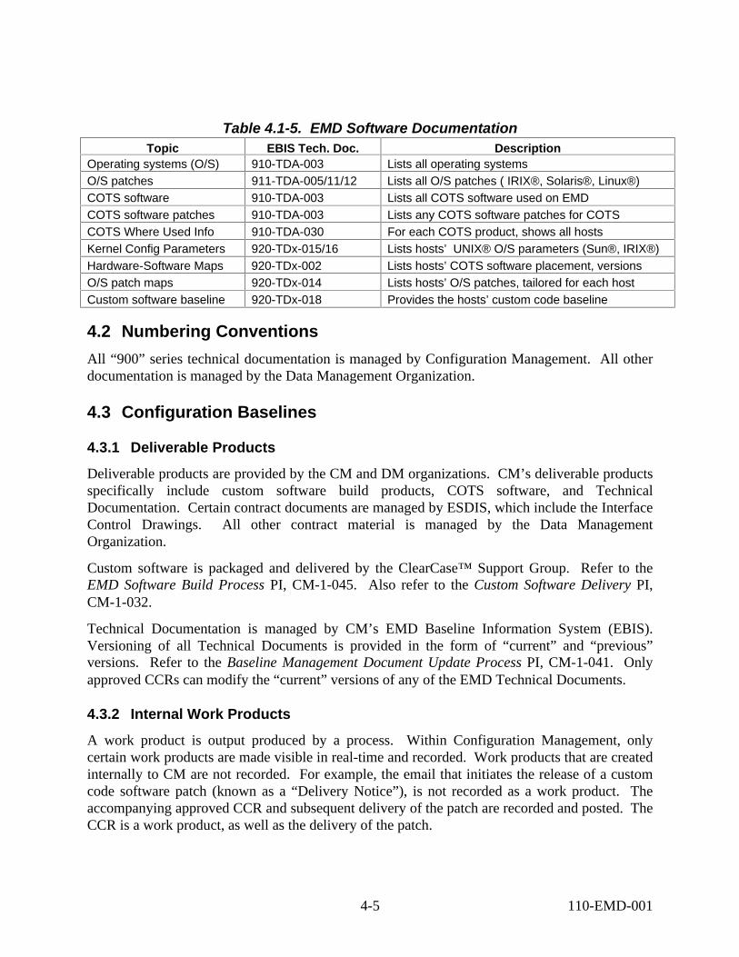
Table 4.1-5. EMD Software Documentation Topic
Operating systems (O/S)O/S patches COTS software COTS software patches COTS Where Used Info Kernel Config ParametersHardware-Software Maps O/S patch maps Custom software baseline
EBIS Tech. Doc. Description 910-TDA-003 Lists all operating systems 911-TDA-005/11/12 Lists all O/S patches ( IRIX®, Solaris®, Linux®)910-TDA-003 Lists all COTS software used on EMD 910-TDA-003 Lists any COTS software patches for COTS910-TDA-030 For each COTS product, shows all hosts 920-TDx-015/16 Lists hosts’ UNIX® O/S parameters (Sun®, IRIX®)920-TDx-002 Lists hosts’ COTS software placement, versions 920-TDx-014 Lists hosts’ O/S patches, tailored for each host 920-TDx-018 Provides the hosts’ custom code baseline
4.2 Numbering Conventions
All “900” series technical documentation is managed by Configuration Management. All other documentation is managed by the Data Management Organization.
4.3 Configuration Baselines
4.3.1 Deliverable Products
Deliverable products are provided by the CM and DM organizations. CM’s deliverable products specifically include custom software build products, COTS software, and Technical Documentation. Certain contract documents are managed by ESDIS, which include the Interface Control Drawings. All other contract material is managed by the Data Management Organization.
Custom software is packaged and delivered by the ClearCase™ Support Group. Refer to the EMD Software Build Process PI, CM-1-045. Also refer to the Custom Software Delivery PI, CM-1-032.
Technical Documentation is managed by CM’s EMD Baseline Information System (EBIS). Versioning of all Technical Documents is provided in the form of “current” and “previous” versions. Refer to the Baseline Management Document Update Process PI, CM-1-041. Only approved CCRs can modify the “current” versions of any of the EMD Technical Documents.
4.3.2 Internal Work Products
A work product is output produced by a process. Within Configuration Management, only certain work products are made visible in real-time and recorded. Work products that are created internally to CM are not recorded. For example, the email that initiates the release of a custom code software patch (known as a “Delivery Notice”), is not recorded as a work product. The accompanying approved CCR and subsequent delivery of the patch are recorded and posted. The CCR is a work product, as well as the delivery of the patch.
4-5 110-EMD-001
4.3.3 Acquired Products
The EMD program currently supports over 150 COTS software products that are installed on over 100 EMD hosts. These acquired products are managed by the ClearCase™ Support Group in the form of an archive, as well as on media. Please reference the EMD COTS Software Library Maintenance PI, CM-1-043. There is also a Work Instruction, COTS Tar File Verification, Preparation, Distribution, and Archiving Procedure, CM-1-043-2.
For the purpose of versioning control, the vendor’s method of version identification is used. There are no standards that exist for versioning. Should the vendor not provide a convenient method for versioning, then a versioning method is applied to the software, either by applying a checksum algorithm to certain binaries, or other methods.
The extension of configuration management to the subcontractors, vendors, and suppliers, is accomplished though the use of the COTS software library. “Golden” copies of vendor supplied software, that is logged and cataloged in this library. Hardware management is performed by the property function of the Remedy ILM system. This is known to CM, but is not controlled by CM.
The EMD Procurement Management Plan provides a further discussion of subcontractor interfaces and controls.
Certain acquired products require licensing for their use. Licenses are managed by the Remedy™ ILM tool, which is not under direct control of CM.
4-6 110-EMD-001
5. Configuration Control
5.1 Configuration Management Objectives
Configuration control is the systematic proposal, justification, evaluation, coordination, approval or disapproval of proposed changes to a baseline, and the subsequent implementation and verification of all approved changes in the configuration of EMD hardware, firmware, and COTS and custom software.
Configuration management provides visibility to components that comprise the EMD system. Unauthorized changes are made visible, as well as configuration drift from the approved EMD baseline. As CM can approve CCRs that are to implemented by the remote sites (DAACs), but CM does not have DAAC authority. It is the specific objective of Configuration Management, then, to provide the information base from which changes can be made, and to provide configuration information by using automated surveillance techniques through remote interrogation.
The objectives of EMD configuration control are to ensure:
• Changes are adequately defined, assessed for technical, cost, and schedule impacts by the EMD office(s), and formally considered by the appropriate CCB.
• Only approved changes are incorporated in the appropriate baseline in an orderly and systematic manner.
• Actions assigned by each CCB are monitored and brought to closure. These consist of:
o Engineering Change Orders (ECOs) reflecting direction to change design
o Document Change Notices (DCNs) reflecting direction to change documentation.
The following paragraphs describe the configuration change control responsibilities and activities to be used in controlling, maintaining, and implementing changes to ECS baselined products.
5.2 Configuration Control Boards
ESDIS/ECS/EMD CM consists of a hierarchy of boards that control the configuration. The hierarchical organization of ESDIS ECS boards is shown in Figure 5.2-1.
5-1 110-EMD-001

ESDIS
EMD CCB
EDF CCB SCDV CCB
Per ESDIS CM Plan
Maintenance
Changes
ESDIS
EMD CCB
DAAC CCBs
EDF CCB SCDV CCB
Per ESDIS CM Plan
Maintenance
Changes
Figure 5.2-1. Configuration Control Boards
5.2.1 ESDIS CCB
The ESDIS CCB is a Level 2 board and is responsible for:
• Interfacing with higher-level boards for changes that affect Level 1 requirements
• Controlling Level 2 requirements
• Approving specified documentation
• Procurements
Specific responsibilities of this Board and details of the ESDIS Change Control process can be found in 423-10-21, Earth Science Data and Information System Project Configuration Management Procedures and 423-10-21-1, Science System Program Control Management Board (SS PCMB) Configuration Management Plan (Level 3).
5.2.2 EMD CCB
The EMD CCB is responsible for establishing and managing the configured baselines at the project level.
Additional responsibilities of this board will be:
• Overall ECS Life Cycle responsibility
• Delegation and allocation of authority and responsibility to subordinate CCBs
• Preliminary IRD, internal and external ICD, inter-segment ICD and any other non-release specific documents
• Contract Waivers
5-2 110-EMD-001

• All Class I CCR (enhancements with cost/schedule impact)
• All Cross-Release or Cross-Segment Class II CCR
• Requirements baseline identifications for both internal and customer-driven milestones
• All purchases with project funds that are within the contractual baseline
5.2.3 EDF (Infrastructure) CCB
The EDF (Infrastructure) CCB is responsible for establishing and managing development, to include:
• Controlling developmental configurations
• Recommending EDF procurements to the EMD CCB
• Approving all non-procurement internal CCRs to change the EDF configuration, COTS hardware/software, networks, facilities, and related procedures
• Controlling all EDF documents
• Installation/removal of all evaluation COTS in the EDF.
5.2.4 SCDV CCB
The Science and Development (SCDV) CCB has the authority and responsibility for controlling ECS releases. For the EMD program, the ECS M&O CCB and ECS SCDV CCB were consolidated into a new EMD SCDV CCB. All ECS M&O CCB roles will now be added to the EMD SCDV CCB. The EMD SCDV CCB will meet once per week to consider:
• Changing the configurations of the EDF test environments (VATC and/or PVC), and/or the DAACs
• Authorizing segment turnovers and/or toolkit distribution and migration
• Approving Class II release-specific changes
• Approving release-specific CDRL documents and others
• Approving, at the Chair’s option, drafts (including EMD CCB-controlled documents), white papers, and technical papers
• Approving ECS Technical Baseline Document changes
• Approving distributions of ECS software and hardware outside of the ECS Development Facility for use within the ECS project. (All other distributions require Raytheon Contract Office authorization.)
• Recommending procurements to the EMD CCB that are within the contractual baseline
• Approving minor enhancement (“perfective”) requests to the operational system
5-3 110-EMD-001

• Reviewing DAAC sponsored, DAAC-unique extensions (DUEs) to the ECS operational system. The DUEs will be reviewed for potential impact to ECS systems and for consideration of future inclusion into the ECS system
• Forwarding major enhancement requests to the appropriate higher level board
• Assuring Requirements Traceability of:
o Level 3 Requirements to IRD mapping
o Traceability of L3s to L4s
o Test Information
o Mapping of Acceptance Tests to Requirements
5.3 Management, Processing, and Administration of MRs and CCRs
5.3.1 Configuration Change Requests
All requests for change are documented using a CCR. A CCR contains the problem description, operations impact, recommended priority, proposed configuration change and/or solution, sites affected, and lists the CI and affected documentation. CCRs are generated against the data base, document/drawing or software/hardware product affected by the proposed change. These requests are submitted to the appropriate CCB for consideration as described in this plan. The CCR also is used for deviations and waivers as described in CM-1-006.
5.3.1.1 Change Classes
Class I and Class II changes are defined in the ESDIS Project Configuration Management Procedures (423-10-21), and are determined by the technical or contractual content of the change.
Class I change is an out-of-contract scope change that affects the form, fit, or function of the ESDIS Project CCB controlled items in one or more of the following ways:
• The technical baselines and the System Specification
• Configuration Items (CI) as specified in the contract.
o Technical requirements.
• Non-technical contractual provisions, to include:
o Contract cost and fee
o Schedules
o Deliverables
5-4 110-EMD-001
• Other factors. To include:
o Government-furnished equipment (GFE)
o Compatibility with support equipment and training devices/equipment
o Configuration to the extent that retrofit action would be taken
Class II change is an in-scope contract change that does not fall within the definition of a Class I change.
Changes that affect the ECS development facility (EDF) are classified as IN. These CCRs are used by Infrastructure to track internal changes and assign work orders.
5.3.1.2 CCR Submissions
Changes are implemented only after completion and approval of a change request generated against the product's technical documentation. All changes indicate a “need date” and are only approved when it is determined that necessary resources are in place to implement the change by the need date.
All change requests are submitted to the appropriate CCB administrator using the CCR and an attached change definition package defining the proposed changes to the applicable drawings or specifications. The organization originating the change request is responsible for providing the information required on the CCR Form and for defining the proposed changes to affected documentation.
CCRs are distributed by the CCB administrator and reviewed for technical, cost, and schedule impact on a scheduled basis by the appropriate CCB. Special CCB meetings are scheduled as required to consider urgent or emergency change requests. Impacts, including those from subcontractors, are reviewed at the CCB meeting and CCB Chairman has final approval/disapproval authority. For Class II changes, the CCB Chairman's approval constitutes authorization to implement the change.
The EMD CCB has sole authority for approval and submittal of Class I changes. Upon approval by the EMD CCB, the CCR is forwarded to the ESDIS CCB as a recommendation. Approval by the ESDIS CCB does not constitute authorization for the contractor to implement changes. The contractor must receive contractual direction to implement any Class I change.
5.3.2 CCB Proceedings
Configuration change control reviews all incoming CCRs for completeness and correctness. The CCR is then entered into CDMTS, assigned a CCR number, and scheduled for the appropriate CCB. At the CCB the CCR is dispositioned in accordance with PI CM-1-004, CCB Change Control Process. The CCB Chairman may assign additional actions required to close this CCR as part of board proceedings. All CCB direction is recorded as a part of CCB proceedings. Engineering Change Orders (ECOs) and Document Change Notices (DCNs) are employed to record board direction.
5-5 110-EMD-001

5.3.3 Request for Deviation or Waiver
Requests for deviations or waivers are initiated using the CCR form as a cover sheet for the deviation or waiver form. These requests are reviewed by the ECS CCB and submitted to the ESDIS CCB for approval. Instructions for preparing and controlling deviations and waivers are described in PI CM-1-006, Configuration Control - Deviations and Waivers.
5.3.4 Implementation of CCB Direction
The following paragraphs summarize the principal CM-related forms and documents that are used in the EMD CM process. Forms and other process documentation are revised as needed to support continuous process improvement.
5.3.4.1 Document Change Notices and Histories
All CCB-approved changes and revisions to configuration controlled documentation are implemented by Document Change Notices (DCN). As DCN are incorporated into documents a history log is updated in the front of the document to define the current configuration of the document in accordance with NASA Specification 500-TIP-2110. DCNs are issued via a transmittal memo. Details for preparation and submittal of DCN are included in Project Instruction DM-1-004, CDRL Item/CDRL and Required Documentation Generation, Review, Release, and Maintenance.
5.3.4.2 Document Revisions
Revisions include any changes necessary to bring the document up to date, incorporation of DCN, or other actions specified by the CCB. Revisions are forwarded to the CCB along with details on changes made to the baselined document as a result of the revision. Once approved by the CCB, the document is posted to the EMD baseline.
5.3.4.3 Document Action Tracking
Open CCRs and any action assigned by the CCB (to include ECO and DCN) will be tracked by Configuration Change Control using a suspense date. The CCB will routinely review these to assure actions are completed by the required date and are closed appropriately.
5.3.5 Configuration Change Documentation
CM regularly records information on CCBs, CCR dispositions, action items, and Engineering Change Orders (ECOs) using the following website: http://dmserver.gsfc.nasa.gov/CCB-BB/ECS/CCB-BB.html.
5-6 110-EMD-001

5.3.6 Configuration Control Support Activities
5.3.6.1 Rough Order of Magnitude (ROM) Board
ECS receives requests from ESDIS for ROM impact analyses of ESDIS CCR. Once received these are directed to the ECS ROM Manager and processed in accordance with Project Instruction PM-1-009, CCR ROM Process, Project Instruction PM-1-010, Engineering Support Directive Process, and Project Instruction PM-1-011, Technical Directive Process. CM provides administrative support to this board and ensures that all actions are recorded, assigned, and dispositioned. The process is shown schematically at Figure 5.3.6.1-1.
Response to ESDISESDIS Engr Spt Direction
Project Manager
ESDIS Import
Analysis
Response to ESDISResponse to ESDIS ESDIS Engr Spt Direction
Project Manager
ROM Mgr Screen ROM Board
Chair & Chief Engineer
ROM Board
ESDIS Import
Analysis
Prop Coord
Others
Prop Coord
Others
Figure 5.3.6.1-1. ROM Impact Analyses
5.3.6.2 Deployment Integrated Product Team (IPT)
The IPT tracks NCR work-off and testing activity and prioritizes work that must be accomplished to test and verify the NCR. The IPT proposes patch contents and schedules to the appropriate CCB.
5.3.6.3 Trouble Ticket (TT) / Work-off of NCR
CM also provides support to EMD Sustaining Engineering for Trouble Tickets that are being forwarded to ECS for resolution. Specific responsibilities for Trouble Ticket (TT) / Work-off of NCR can be found in PI MO-1-003, ECS SDPS Sustaining Engineering and Maintenance Management and WI MO-1-003-4, ECS Deployment IPT Work Instruction.
The remainder of this section describes the management of the corrective, perfective, and maintenance changes to the operations configuration baseline.
5-7 110-EMD-001

The activities that are required are:
• Document, manage, resolve and report problems with the operational configuration.
• Propose, review and adjudicate corrective and perfective changes to the operations system configuration.
• Develop and deploy the configuration changes to operations.
• Maintain the operational baseline including approved/shipped and installed change statuses.
5.3.6.4 ECS SDPS Modification Request Process
Modification requests (MRs) may be submitted from the ESDIS Project, the DAACs (including the SMC, EDC, GSFC, LaRC, and NSIDC), and the user community, as well as EMD project staff. MRs can include requests for corrective, adaptive, and/or perfective changes. All technology refresh requests, including both hardware and software, are to use the MR process. Currently, the ROM Board and CCBs are used to implement the MR process. The EMD Change Manager (ECM) tool, which is currently in development, may be used to facilitate the Modification Request process. See section 5.6.8 for a discussion of the ECM tool.
5.3.7 Configuration Problem Management
Problems (corrective or perfective) are documented in a trouble ticket database and submitted to the Remedy™ trouble ticket database. The Tele-conference, with members from EMD sustaining engineering and the DAACs, review the impact, assign an initial priority, and assign the problems for investigation. A more detailed description of these activities can be found in the PI MO-1-003, ECS SDPS Sustaining Engineering and Maintenance Management, WI MO-1-003-4, ECS Deployment IPT Work Instructions, WI MO-1-003-6, DAAC Help Desk Support Work Instruction, WI MO-1-007-1, Problem Review Board, and MO-1-008-1, Priority Review BoardProcess.
5.3.8 Configuration Change Adjudication
The Deployment IPT includes the SCDV CCB chairperson and members from EMD Operations Deployment and DAACs. Using the results of the NCR Prioritization Team, the IPT tracks NCR work-off and testing activity. The IPT conducts the PSR for patches and reviews the patches with the receiving SMC and DAAC. The PSR includes a description of the system changes and associated documentation changes including the test results (as found during testing in the EDF facility). The operations procedure changes, configuration baseline changes (including database changes), and installation instructions are also part of the PSR.
CM delivers the patch to the CCR designated sites using the ClearCase™ Delivery Tool. At this point, baseline changes are reflected in the EMD Baseline as delivered products.
For problems that require perfective changes to the operational baseline, the SCDV CCB reviews the CCR. If a perfective-change CCR is approved by the SCDV CCB, ECO and DCN will be
5-8 110-EMD-001

recorded and assigned to accomplish development, deployment and installation of the change. The SCDV CCB also statuses and reports the progress of the CCR/ECO/DCN closure actions.
If any proposed change results in a cost and/or schedule impact exceeding the SCDV CCB level of authority, or involves a change to System Level 3 requirements or external interfaces, the Class 1 CCR will be forwarded to the EMD CCB for adjudication
5.3.9 Development, Deployment and Installation of Changes
The EMD sustaining engineering organization develops custom software, procures COTS software, proposes changes, and tests the changes within the current operational baselined configuration at the EDF test facility. In addition to coordinating patch content and schedule as members of the Deployment IPT, the EMD sustaining engineering organization provides the installation instructions, configuration baseline changes, and requirements/design documentation changes.
CSG ships the physical media, or delivers the files using the ClearCase™ Delivery Tool to the designated sites. Custom code surveillance establishes the insertion times of the delivered custom code into OPS mode, and reflects the delivery and insertion within the Custom Code Tracking page.
5.4 DAAC Unique Extensions (DUEs)
The DAACs may identify and develop site unique changes to their DAAC baselines in the form of DAAC Unique Extensions (DUEs) and provide required information to the SCDV CCB via CCR. A DUE may include hardware additions and re-configurations, operating system re-configurations, database modifications, COTS software configuration changes, and COTS software additions/reallocations to the baseline. The SCDV CCB will review the DUEs for potential impact to the ECS Configuration Baseline System and for potential inclusion in the ECS Baseline System. If warranted, the SCDV CCB authorizes inclusion in the ECS Configuration Baseline System. DUEs that are recommended for baseline inclusion, but are thought to be out of scope, will be forwarded to the ESDIS CCB for resolution.
5.5 Software Configuration Management
Software Configuration Management (SCM) uses the CCR process to release COTS and custom software to the sites.
Figure 5.5-1 below, shows the SCM Tools Overview for Custom Code, and their functional interrelationships. There are three columns. The first column describes the SCM tools that are used. The second column states the vehicles that are used to convey the information, such as a NCR associated with the DDTS™ tool. The third column briefly states each SCM tool’s purpose.
As the process shows, a custom software component can only change with the issuance of an NCR using the DDTS™ tool. The base upon which the change is made is the custom code design baseline, which is maintained by the ClearCase™ software configuration management
5-9 110-EMD-001

tool. An NCR may originate in several ways, but the two primary methods are from the conversion of a DAAC Trouble Ticket (Remedy™), or an in-house observation from within the VATC, PVC, or EDF.
Upon problem resolution, a Developer generates a Merge Form using STTS, and attends a daily merge meeting. Upon approval, the code is merged into a specified baseline, with CSETs being emitted from the ClearCase™ support scripts. Once all merges are in, through the verification of the CSET emails, the ClearCase™ system baseline is ready for a build.
System builds are controlled by a UNIX® “crontab”. A “crontab” is a list of commands that execute automatically at a given time. This “crontab” needs to state the baselines that are targeted for rebuild. Once reprogrammed, the distributed and automated builds execute without any manual intervention, producing build products. System level builds are performed twice per day. A NightlyBuild web status page is updated that shows any build errors.
Build products and files are then selected, with a focus on those subsystem components that were affected by the just-merged code. These selections are conveyed by email to CSG. Upon receipt, the Delivery Tool GUI is used to select the baseline, and assemble the file set stated in the email. These file sets may contain the entire build (a “Drop”), a set of packages (Patch or TE), and/or specific discrete files (Patch or TE).
The Delivery Tool automatically transmits the prepared files into the EDF, PVC, and VATC, for subsequent installation at the discretion of the site. No CCR is required for in-house transmittals. After installation, the files are tested to ensure that the NCRs for which they were merged are addressed.
A CCR can be submitted to the CCB for approval. A Delivery Notice will then be issued, and upon receipt of the notice by CSG, the specified software will be transmitted to the CCR specified sites (targets). All custom code deliveries are logged on the Custom Code Tracking page. This tracking page will also include certain dates, as well as NCRs, CCRs, and comprehensive file lists for each delivery. The Delivery Tool will also notify the sites’ configuration management personnel of the deliveries.
Once the CCR targets have received the code, they can install it into any mode according to site processes. The operating modes at all the DAACs are OPS and TS1, with some sites having TS2, TS3, TS4, etc.
Should any further software performance problems arise, the remote site(s) will initiate a Remedy™ trouble ticket, or a DDTS™ NCR will be generated in-house, and the cycle will repeat.
5-10 110-EMD-001

Figure 5.5-1. SCM Tools Overview for Custom Software
5-11 110-EMD-001

Software Configuration Management is separated into two major process areas, those processes that are event driven, and those that are automated and/or real-time.
5.5.1 Event Driven Processes
Event driven processes are those processes driven by receipt of an email, such as a file preparation request, a CCR approval for release of COTS or custom software, or other specific requests.
5.5.1.1 Merge Process
Please refer to the Merge Access Process Instruction, CM-1-046, for the Merge Process details.
Formal controls are in place to control version changes to the EMD baselines. A Software Turnover Tracking System tool (STTS) provides the mechanism for applying custom software code changes to the EMD baseline. In order to change the EMD baseline, merge access must be granted by a member of CSG, and authorized at the Daily Merge Meeting. This ensures that only authorized changes are made to the baseline. The STTS tool provides a unique merge identification number.
The software integration management team holds a Merge Meeting each day, to be attended by the software subsystem leads, CSG, the Deployment Team, and the Test CPT Lead. The subsystem leads discuss the characteristics of each merge request. This includes the baseline(s) to which it will be merged, its impact on components outside the submitted subsystem, the changes in installation or operation procedures, its need date and impact on the Monthly Patch Plan (CDRL #020, 112-EMD-001), and the test plan for verifying the fix. The request may be approved for merging that day, may be deferred until the completion of some other event (such as another merge or the creation of a patch file), or may be sent back for further re-work.
Once all Merge Requests are dispositioned, the builds will be scheduled. The existing SDPS infrastructure supports the overnight build of two baselines; if merges of compilable code are approved for more than two baselines, the build of one or more baselines will be deferred, and the activities of all those affected will be adjusted accordingly. The Software Installation CPT decides which baselines will be built, balancing the needs and priorities of all of the baseline stakeholders.
5.5.1.2 View Deletion Process
Please refer to the EMD ClearCase™ View Deletion Process Work Instruction, CM-1-044-1, for a description of the view deletion process.
The view deletion process is run twice per month to ensure that views that are no longer in use are removed. This ensures that ClearCase™ tool operates efficiently, and ensures that disk space is maintained.
5-12 110-EMD-001

5.5.1.3 Subsystem Build Process
Subsystem builds are performed by the ClearCase™ Support Group (CSG). These builds generate the build products of a recently merged set of source files, such as executables. Subsystem builds are performed upon request from a Developer. Subsystem builds are performed to ensure that the twice-daily system level builds run successfully.
5.5.1.4 Custom Software Preparation Process
After all approved code has been merged to the baseline, a software build is performed. This is a regularly scheduled process discussed in Section 3.9.2.1. Once the build is complete, build products are selected for preparation. The custom software preparation process is driven by an email request. The ClearCase™ Delivery Tool is used to assemble the build products, in accordance with the COTS and Custom Software Preparation and Delivery Work Instruction, CM-1-032-1.
Once the file set for a TE or Patch is created by CSG, the test organization installs the software into a sustaining engineering mode in the PVC. This mode is permanently allocated to the testing of sustaining engineering deliveries. Test will execute the installation
5.5.1.5 COTS and Custom Software Release Process
The ClearCase™ Delivery Tool is used to deliver software, in accordance with the COTS and Custom Software Preparation and Delivery Work Instruction, CM-1-032-1.
COTS software can only be released with the authority of an approved CCR. The CCR contains the sites that receive the software, as well as defines precisely the file(s) that are to be delivered. At this time, the files are copied from host “lemmings”, and verified, to the /ARCHIVE/COTS archive. The ClearCase™ Delivery Tool is then used to automatically transmit the file(s) to the designated sites. Email is automatically generated to inform all pertinent individuals of the delivery. Subsequently, the COTS Software Tracking page is updated with the COTS software delivery information on server “pete”, and then the information is replicated to server “cmdm”.
Custom software can only be released with the authority of an approved CCR. The CCR contains the sites that receive the software, as well as defining precisely the file(s) that are to be delivered. At this time, the files are copied from the preparation area and verified within the /ARCHIVE archive. The Delivery Tool is used to automatically transmit the file(s) to the designated sites. The custom software delivery process is the same as the COTS software delivery process.
In the case of inadvertent deletion of the transmitted files at the sites, no further paperwork is required to re-transmit the software.
5.5.1.6 Web Tracking Pages Update Process
Accurate records are kept for all event-driven processes. This is implemented through the use of web tracking pages. Web tracking pages are kept for COTS software deliveries, custom software deliveries, Release Notes documents, Engineering Technical Directives, Engineering
5-13 110-EMD-001

Software Deliveries, and approved CCRs. These pages are incrementally updated, in accordance with their respective Project or Work Instructions. Both the internal and external web servers maintain the same information, with the internal server “pete” being updated first, with replication to the external web server “cmdm”.
5.5.1.7 Source Code Delivery Process
Within the PVC, the source code files, object file, and certain libraries are required in order to support the use of the source code debugger, dbx. This process is used to transmit the correct source code versions into the PVC environment, so that the debugger can be used to help diagnose integration issues with new versions of custom code executables. The scripts ensure the correct synchronization of the ClearCase™ build products, source, object, and libraries. The ClearCase™ DeliveryTool controls the source code delivery process.
5.5.2 Automated and Real Time Processes
Automated and Real Time EMD Software Configuration Management processes are autonomous, can be stopped and started, and have certain parameters that can be modified to accommodate changes for increased capacity or different performance characteristics.
5.5.2.1 Nightly Build Process
Two system level builds are performed daily. Please refer to the EMD Software Build Process Project Instruction, CM-1-045. There is notification of any errors from the build, and a web page is available to indicate the build results. Responsible parties are notified should there be any problems.
5.5.2.2 Embedded Versioning
Each build provides embedded versioning for all of the executables. Please refer to Project Instruction CM-1-031, Embedded Versioning, for details. Each executable has specific information inserted into the binary at the time of the compilation and linking. This information is retrievable by using the UNIX® “what” command. Embedded information consists of a unique build identifier, a build timestamp, the ClearCase™ build view, and the ClearCase™ configuration specification, and the build host. This identification method provides absolute certainty in the determination of an executable’s version and build history.
5.5.2.3 View Management
A custom utility, Round Robin, is used manage the placement of newly created ClearCase™ views. This utility provides the ClearCase™ user with the best view server performance available. A new view is automatically created on the view server that is the least busy, and is created on the view server disk that has the most available disk space. A web page is available to provide visibility, and is only visible from within the Landover facility at URL:
http://pete.hitc.com/baseline/ClearCase/html_file
5-14 110-EMD-001

5.5.2.4 Engineering Software Delivery
The Engineering Software Delivery Daemon is used to provide immediate fixes to any site as quickly as possible, without compromising the integrity of the custom code baseline. Project instruction CM-1-049, Engineering Software Delivery, fully describes the process. Insertion of the software into any mode is at the DAACs’ discretion. A tracking page documents all engineering software deliveries, and can be seen by everyone at URL:
http://cmdm.east.hitc.com/baseline/CUSTOM_SOFTWARE/ESDeliveryTracking.html
5.5.2.5 Custom Code and COTS Software Surveillance
In order to provide configuration status metrics for the EMD program, automated surveillance methods are used. Direct interrogations of managed hosts, located at Landover and at the DAACs, are performed on a regular basis. The frequency of each type of interrogation is configurable. Currently, custom code interrogations are performed daily across all modes on all hosts at all sites. COTS software interrogations are performed on a weekly basis, as well as kernel operating system parameters and operating system patches interrogations.
This information is posted on both EBIS web servers. This “As-Built” data provides near real-time visibility of custom software files, and shows the CCRs that have not been implemented.
5.5.2.6 ClearCase™ Lab Staging
The Software Integration Lab is used for debugging problems, testing fixes, integration of fixes at the subsystem and system level, and regression testing. The lab modes are configured to execute the currently built baseline under software CM; this baseline is refreshed automatically from the Nightly Builds. With the permission of the lab lead, developers also are able to execute components of the system within a mode from builds performed in their personal ClearCase™ views, so that they can compare baseline performance to the behavior resulting from their changes. The lab also provides a collaborative environment where developers from one or more subsystems can work together to solve particularly complex problems.
5.5.2.7 Remedy™ ILM File Routing
Remedy™ COTS software is used for license management, property management, and maintenance. In support of these functions, CSG scripts are executed to export and import the files that are necessary for keeping enterprise accountability. The execution of these scripts is controlled by a CSG UNIX® crontab function. A drop down menu from within the ClearCase™ Delivery Tool allows the process to be stopped and started. The times of execution can also be modified. Please refer to the COTS and Custom Software Preparation and Delivery Work Instruction, CM-1-032-1, for the Remedy™ ILM file routing control methods.
5.6 Software Configuration Management Tools
A suite of Configuration Management tools is used to manage the information for the EMD program. Some of these tools are COTS software, some are enhanced COTS software, and some
5-15 110-EMD-001
are entirely custom software. Please refer to Figure 5.5.1, SCM Tools Overview for Custom Software, to complement the sections below.
5.6.1 Remedy™ Trouble Ticketing
Trouble tickets are created to electronically convey a description of a problem, an unresolved operational problem, or a question discovered at one or more DAAC sites. Trouble tickets are managed within the Remedy™ COTS software application. Remedy™ stores, maintains, and facilitates tracking of trouble tickets. A Problem Review Board (PRB) meets daily to review new, deferred, and aged trouble tickets. Non-conformance reports (NCRs) are generated into the Landover Distributed Defect Tracking System (DDTS™) to enable the original trouble ticket to be worked. Please refer to Work Instruction MO-1-007-1, Problem Review Board, for further discussion.
5.6.2 Distributed Defect Tracking System (DDTS™)
The DDTS™ COTS software product is used for the generation, tracking, and resolution of Non-conformance reports (NCRs). Refer to Development Planning and Tracking of Operational NCRs Project Instruction, SD-1-034, for details regarding the use of DDTS™. Software Configuration Management relies heavily on DDTS™’s ability to relate NCR numbers to software problems. DDTS™ has been configured for the EMD program. Also refer to Work Instruction MO-1-003-5, Operations Class NCR Management Process.
5.6.3 Software Turnover Tracking System (STTS)
This custom tool will continue to be used as the merge interface to the system baselines. Please refer to Project Instruction, SD-1-028, ECS Merge Process for details concerning STTS. NCRs are required entries for STTS merge forms. STTS is a custom software utility that was designed and implemented on the ECS contract (NAS5-60000). By relating NCRs and specific custom software files within merge forms, STTS provides the functional bridge between the DDTS™ tool and the ClearCase™ tool.
5.6.4 ClearCase™ Software Configuration Management System (ClearCase™)
Development and CSG use the ClearCase™ tool and well-established configuration management processes to provide support for multiple custom software baselines. This enables development of new capabilities in parallel with the delivery of small incremental changes to the field.
Developers use ClearCase™ to maintain multiple private views of the software, enforce module checkout and check-in rules, and manage the process of merging changes. When a developer completes a fix in his or her view, he or she submits a Merge Request using the custom STTS tool. This tool maintains merge and build requests, routes them to appropriate reviewers, and tracks their completion. The lead engineer for the affected software subsystem reviews and approves the Merge Request, or direct the developer to make necessary changes. If a merge needs to be made to multiple baselines, a Merge Request is submitted for each baseline.
5-16 110-EMD-001
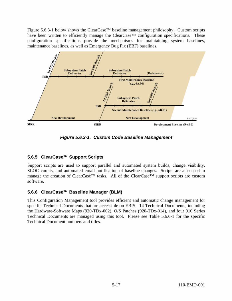
Figure 5.6.3-1 below shows the ClearCase™ baseline management philosophy. Custom scripts have been written to efficiently manage the ClearCase™ configuration specifications. These configuration specifications provide the mechanisms for maintaining system baselines, maintenance baselines, as well as Emergency Bug Fix (EBF) baselines.
Figure 5.6.3-1. Custom Code Baseline Management
5.6.5 ClearCase™ Support Scripts
Support scripts are used to support parallel and automated system builds, change visibility, SLOC counts, and automated email notification of baseline changes. Scripts are also used to manage the creation of ClearCase™ tasks. All of the ClearCase™ support scripts are custom software.
5.6.6 ClearCase™ Baseline Manager (BLM)
This Configuration Management tool provides efficient and automatic change management for specific Technical Documents that are accessible on EBIS. 14 Technical Documents, including the Hardware-Software Maps (920-TDx-002), O/S Patches (920-TDx-014), and four 910 Series Technical Documents are managed using this tool. Please see Table 5.6.6-1 for the specific Technical Document numbers and titles.
5-17 110-EMD-001

Table 5.6.6-1. ClearCase™ BLM Technical Documents Document Title
910-TDA-003 COTS Software Version Baseline Report 910-TDA-005 Site-Host Map Report 910-TDA-023 Critical COTS Software List 910-TDA-030 COTS Software Where-Used Reports (plus 275+ referenced 920-TDE-002 LP DAAC Hardware-Software Map 920-TDG-002 Goddard DAAC Hardware-Software Map 920-TDL-002 LaRC DAAC Hardware-Software Map 920-TDN-002 NSIDC DAAC Hardware-Software Map 920-TDS-002 SMC Hardware-Software Map 920-TDP-002 PVC Hardware-Software Map 920-TDV-002 VATC Hardware-Software Map 920-TDE-014 LP DAAC Operating System Patches 920-TDG-014 Goddard DAAC Operating System Patches 920-TDL-014 LaRC DAAC Operating System Patches 920-TDN-014 NSIDC DAAC Operating System Patches 920-TDS-014 SMC Operating System Patches 920-TDP-014 PVC Operating System Patches 920-TDV-014 VATC Operating System Patches
In addition, approximately 275 “where-used” reports are generated with each baseline update. This tool uses ClearCase™ Versioned Object Bases (VOBs) for data and script storage, and uses a customized GUI and custom scripts. The tool provides all of the change visibility benefits inherent in the ClearCase™ tool. For more detail, please reference Project Instructions CM-1-041, Baseline Management Document Update Process.
5.6.7 Configuration Data Management Tracking System (CDMTS)
The CDMTS tool is used to provide CCR change management. This tool is used by the CM and DM organizations. CDMTS provides and tracks CCR numbers, and Engineering Change Orders (ECOs), as well as Action Items, are tracked. Please refer to Project Instruction CM-1-004, CCB Change Control Process for details. Report Writer™ is used with CDMTS to provide meeting agendas and open ECO lists.
5.6.8 EMD Change Manager (ECM)
The new EMD Change Management tool, which will be based on ClearCase™, will provide real time configuration status accounting. Informational reports will be accessible using the Web. The new tool will provide configuration status accounting and improved change visibility. This tool will use the ClearCase™ COTS software tool to manage version changes of the information, in conjunction with custom scripts to provide the web pages and interfaces. In addition to
5-18 110-EMD-001
replacing the current CDMTS tool, this tool will be used to facilitate the Modification Request (MR) function as delineated in the EMD Task Order 101 Statement of Work. Modification requests will first come into a Modification Review Board. Requests that are not new requirements, or do not require new funding, will proceed towards implementation, while new requirements will cause the creation of a System Engineering Proposal. The System Engineering Proposal will be subject to Government review, with subsequent approval or disapproval. Those MRs that are approved will then move forward for implementation. The new ECM tool will provide tracking and visibility of all Modification Requests, and will implement the Modification Request functionality.
5.6.9 ClearCase™ Delivery Tool
The Delivery Tool is a custom tool that is used for the preparation and delivery of custom code software, as well as COTS software. This tool manages CD-ROM archiving of custom and COTS software. Refer to Project Instruction CM-1-032, Custom Software Delivery, for more details.
5.6.10 Engineering Software Delivery Daemon
Refer to Project Instruction CM-1-049, Engineering Software Delivery for an in depth description of the Engineering Software Delivery process. The Engineering Software Delivery process exists to ensure that rapid fixes can be made to configuration controlled hosts without compromising the custom code baseline. Complete change visibility is provided at URL:
http://cmdm.east.hitc.com/baseline/CUSTOM_SOFTWARE/ESDeliveryTracking.html
5.6.11 Source Code Delivery Tool
This tool consists entirely of custom scripts. Its purpose is to deliver all EMD source files, object files, and libraries to the PVC. This tool accurately installs these files to support the debugger. Execution of the debugger allows developers to quickly resolve integration problems with the recently built code. Because the PVC is isolated from the EDF, the PVC hosts cannot directly access the ClearCase™ repositories.
5.6.12 Custom Code Installation Emulator
This tool generates an installation image of all custom code files for a particular Drop or Patch. It overlays any new releases onto the Real Time Delivered Custom Code Baseline technical documents, 920-TDx-018. This tool provides the information necessary to convey the expected files, file versions, file permissions, and files paths, dates, and authorizing CCRs, for every custom code file for every EMD host for OPS mode.
5.7 EMD Baseline Information System (EBIS)
The EMD Baseline Information System (EBIS) is used to convey the configuration states of all configurable items. All items managed within EBIS are versioned, using “Current” and “Previous” directories. EBIS is implemented with two physical web servers, pete and cmdm.
5-19 110-EMD-001
Server pete resides within the Landover firewall, and is not accessible to outside users of the Internet. Server cmdm resides outside the Landover firewall, and can be seen by anyone with Internet access. For security reasons, certain technical documents, such as those showing IP addresses and network diagrams, are only viewable internally on pete. More than 98% of all technical information is replicated to cmdm. Figure 5.7-1 shows the EBIS web page. The EBIS URLs are:
http://pete.hitc.com/baseline/ (Internal EBIS web server)
http://cmdm.east.hitc.com/baseline/ (External EBIS web server)
5-20 110-EMD-001
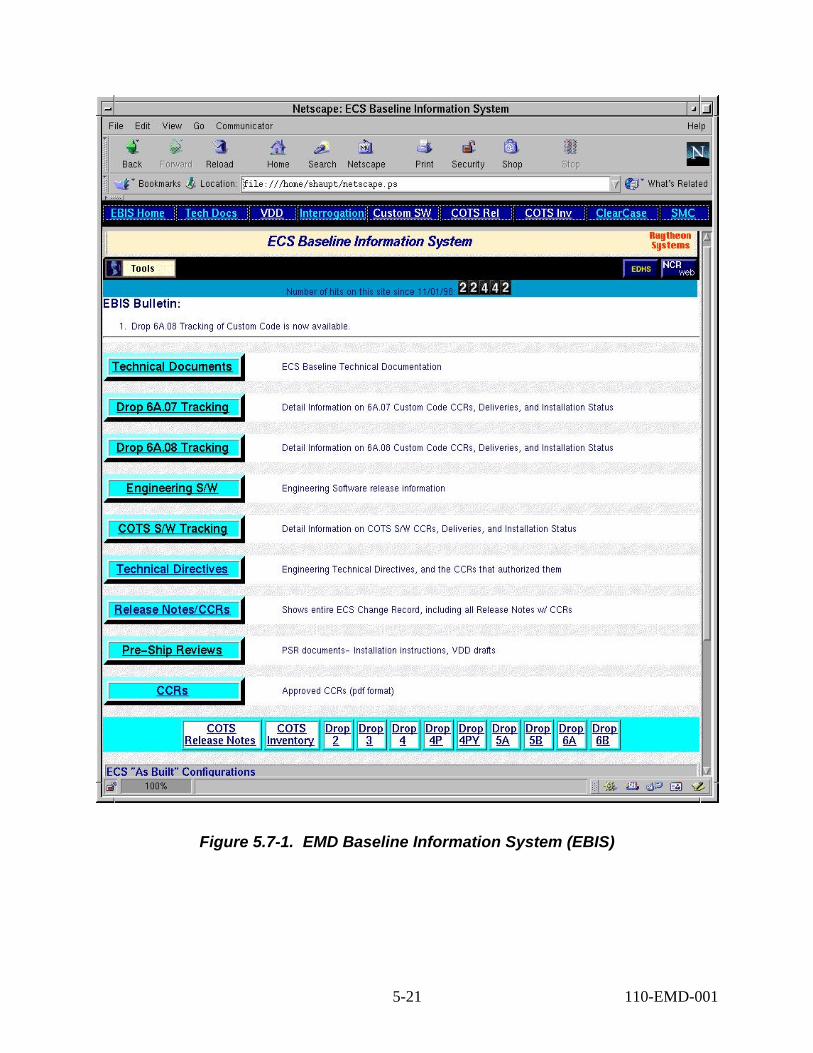
Figure 5.7-1. EMD Baseline Information System (EBIS)
5-21 110-EMD-001

The information on pete and cmdm is logically arranged. Each of the web pages may be searched using the “Edit/Find in Frame…” feature provided by the web browser. There are 8 sets of information:
1) Technical Documents – EMD baseline technical documentation includes the 900 series documents. General baseline information is provided within the 900 series.
2) Custom Code Drop Tracking – For each release of customs software, tables are updated to show the ECS Patch, Custom code nomenclature, date, CCR, NCRs, files, and targeted sites. The CCR, NCR, and files cells are hyperlinked to provide ready access to the related information.
3) Engineering Software – For each automatic delivery of Engineering Software, a table is updated indicating a Sequence Number, nomenclature, sender, date, NCRs, files, and sites. The NCRs and files’ cells are hyperlinked.
4) COTS Software Tracking – For each COTS software delivery, the ECS COTS Release number, nomenclature, date, CCR, and target sites are provided.
5) Technical Directives – Engineering Technical directives are provided. This table indicates the ETD number, title, date, and CCR number for each Technical Directive. The document title and CCR numbers are hyperlinked.
6) Release Notes – Release Notes are provided along with the approved CCRs. Versions and dates are also provided. The page is searchable for titles, component COTS software, versions, and CCRs. The document and CCR cells are hyperlinked.
7) Pre-Ship Reviews – This collection of documents provide customer with in-work versions of Release Notes documents for review.
8) CCRs – This provides a listing of all approved CCRs. Each CCR is retrievable for viewing.
These web pages provide all of the information needed to define what comprises the EMD system, as well as the histories of the EMD system. This data is to be used as a reference from which proposed design changes to the EMD system can be made.
5.8 Library Maintenance
The EMD program uses two distinct libraries. The first library is named the Document Center, and the second is named the COTS Software Library. The Data Management group maintains the Document Center, and the ClearCase™ Support Group of Configuration Management manages the COTS Software Library.
5.8.1 COTS Software Library
The COTS Software Library is used to maintain computer media copies of all EMD COTS and custom software. Work Instruction CM-1-043-1, EMD COTS Software Library Activities provides the details of day-to-day management of the COTS Software Library.
5-22 110-EMD-001
6. Configuration Status Accounting (CSA)
6.1 Configuration Status Reports
Configuration Status Reports is an area that is being improved for the EMD program. The current CCR tool, CDMTS, is to be replaced by a more powerful tool, the ClearCase™ EMD Change Manager (ECM) tool. The CDMTS tool provides limited Configuration Status Accounting (CSA). The new web based tool, ECM, is planned to provide the following items on servers pete and cmdm:
• On-line Engineering Change Orders
• On-line attachments of all CCRs in process
• Status accounting pages will allow a user to quickly view any CCR(s) of interest
• The new tool will provide electronic signature capability
• Status pages will also be continuously updated to show the CCRs that have been initiated, approved, deferred, rejected, and closed
6.2 To Be Resolved (TBR) / To Be Determined (TBD) Reports
The 910-TDA-003 report tracks “TBD” information. This information has not yet been provided to CM. Discrepancy reports use color to indicate “TBR” information. Yellow is used for non-critical COTS software, and red is used for critical COTS software. If a critical COTS software is missing, then the product shows as red. The Operating System patch reports use red for missing and gray for “installed-but not-baselined”. In all cases, the green color is used to convey that the design baseline and the “as-built” are in agreement. These are the To Be Resolved reports, and are provided on both the Internal and External web sites on pete and cmdm, respectively. All of the report formats have been optimized to convey the most amount of information in the least amount of space. In html format, they are directly readible from web browsers without the use of Adobe® Acrobat reader.
6.3 As-Built Records Format, Content, and Process
Extensive use of automated scripts provide near real-time “as built” records. These records are provided on the EBIS web site under the “Interrogation” button. All reports are generated in html format, so that the web pages load quickly for the user.
6-1 110-EMD-001

This page intentionally left blank.
6-2 110-EMD-001
7. Configuration Audits
Configuration auditing validates that all change control processes are functioning. Audits are conducted to verify that CCRs are being correctly executed for baseline Technical Documentation updates and host configuration changes. These audits compare the baseline Technical Documentation to the “as built” configurations of managed EMD hosts. Validation is accomplished by comparing what happens (as-built configurations) to what should have happened (approved CCRs). Discrepancies are noted and resolved.
7.1 Process Audits
The Quality Office is responsible for auditing Configuration Management processes. The purpose of these audits is to ensure that the actual steps being taken and the artifacts produced are in accordance with published and managed Process Instructions and Work Instructions. Deficiency Notices are issued should there be any findings, in accordance with Quality Assurance procedures.
7.2 Physical Configuration Audits
Physical Configuration Audits (PCAs) are formal assessments of the actual configurations of all baselined EMD hosts. Specific EBIS technical documents are used as audit references. Refer to Project Instruction, CM-1-009, Physical Configuration Audit, for process details. There are two types of audits, a software PCA and a hardware PCA. Software PCAs compare the COTS software, custom software, O/S patches, and UNIX® kernel parameters of the actual hosts to the EBIS design baseline. Hardware PCAs compare the physical hardware to the EBIS design baseline, and covers items such as memory, disks, and host configuration.
7.2.1 Software PCA
Automated interrogation scripts provide the “as built” configurations in support of Software PCAs. Discrepancy reports are generated for each host at each site, and summary reports are generated. Please refer to PI CM-1-009, Physical Configuration Audit, Work Instruction CM-1-009-1, Conduct of Software PCA (OS, COTS, Custom Code), WI CM-1-038-1, Host Interrogations, and WI CM-1-037-1, Discrepancy Report Generation. Formal summaries are posted at URLs specified in the process and work instructions.
Software PCAs are conducted for each baselined EMD host, and include COTS software, Operating System (O/S) patches, custom code, and UNIX® kernel parameters. Each attribute is checked for presence or absence, correct/incorrect version, and correct/incorrect installed path, or correct/incorrect value. Automatically generated discrepancy reports are analyzed and corrective actions are taken. The stated purposes of the software PCAs are to ensure that the design baseline is accurately reflected in the actual systems, and to ensure that approved CCRs that
7-1 110-EMD-001

affect COTS software, O/S patches, custom code, and UNIX® Kernel Parameters, have been executed.
Figure 7.2.1-1, COTS Software Discrepancy Report, shows a typical report for the COTS software comparisons for one host. The COTS PRODUCT name in the first column is compared for both versions and installed path. The ClearCase™ BLM BASELINE shown in the second column is derived from the 920-TDP-002 report for host p2acs02, and the ASBUILT CONFIGURATION shown in the third column is derived from the output of the COTS software interrogation scripts. Specially designed algorithms compare the design baseline in column two to the “as-built” baseline is column three. Color is used to convey correctness and COTS software criticality from the 910-TDA-023 report. Similar reports exist for O/S patches, custom code, and UNIX® kernel configuration data.
Figure 7.2.1-1. COTS Software Discrepancy Report
7-2 110-EMD-001

In conjunction with the 920-TDx-002 Hardware-Software maps, complete change traceability is provided. By looking at a particular COTS software product for a specific host in the 920-TDx-002 document, in-line entries for the authorizing CCR and the applicable Release Notes information are found.
7.2.2 Hardware PCA
Hardware PCAs ensure that the hosts’ hardware configurations are in accordance with the hardware design documentation. By comparing the systems’ floor configurations to the design baseline, the integrity of the design baseline and change control processes are maintained. Please refer to Work Instruction, CM-1-009-2, Conduct of Hardware PCA, for further details. Hardware PCAs are manual audits because of their nature.
7.3 Functional Configuration Audits
Functional Configuration Audits (FCAs) are conducted to assure that each EMD product meets its specified performance requirements to the extent determinable by testing. The Quality Assurance Office conducts the FCA with CM assistance in accordance with Project Instruction CM-1-036, Functional Configuration Audits.
7.4 Audit Reports
Audit reports are presented at Consent to Ship Reviews (CSRs) and/or Release Status Reviews (RSR) as scheduled. Audit reports summarize the configuration integrity of the design baseline, “as built” configurations, as well as change control processes, for software and hardware.
Figure 7.4-1, COTS Software Site Audit Report, shows a summary of the COTS software findings at one site (PVC). These reports are generated from the COTS software discrepancy reports and are used as primary contributors for technical reviews, such as CSRs and RSRs. Similar reports exist for custom software audits, O/S patch audits, and UNIX® kernel parameter audits. This particular report shows that 83.5% of the design COTS S/W, versions, and installed paths, agreed with the “as built” configuration at the time of the audit.
7-3 110-EMD-001

Figure 7.4-1. COTS Software Site Audit Report
7-4 110-EMD-001

8. Data Management
8.1 Data Management Organization
The Data Management Organization (DMO) is an engineering function and supports the EMD Program Management and IPT Tasks. DM is viewed as a support organization to the EMD Project team, the GSFC ESDIS project office, personnel at archiving centers and other agencies, and consumers within the science community.
8.2 Data Management Goals and Objectives
The primary goal of the EMD DMO is to provide the data services and functions necessary to create, control, deliver, archive, and update data critical to documenting the EMD project. The objectives of the DMO are:
• Establish all documentation and data requirements, including specifications and standards to be followed in generating such documentation and data requirements, and to ensure accurate and timely preparation of these deliverables.
• Establish task assignments and schedules for document preparation and release; coordinate with EMD offices responsible for generating documents to ensure on-time schedule.
• Establish and maintain procedures for controlling document masters, preparing formal document changes, and keeping auditable records of changes.
• Maintain status records and produce status reports for tracking and controlling the deliverable documentation specified in the CDRL.
• Coordinate and ensure the release of all final documents in hard copy and electronic media in accordance with the approved standards.
• Implement and operate an on-line automated ECS Data Handling System (EDHS) that permits users with Internet access to interactively search and download documentation.
8.3 Data Management Responsibilities
8.3.1 Identifying Data Requirements
The DMO is responsible for ensuring that all documentation/data requirements are identified for any given activity. The Contracts Data Requirements Document (CDRD), Raytheon procedures, and EMD Project Instructions establish the requirements for document content, generation, distribution, and delivery. As appropriate, the DMO will assist ESDIS in updating the CDRD, and in identifying additional supporting ECS documentation to be archived and maintained.
8-1 110-EMD-001

8.3.2 Document Numbering
Each document is assigned a unique number to ensure that the document and any revisions can be easily and accurately identified. Once a number has been assigned to a document, that number will remain the same for the life of the project. Each first submission of a document is considered to be Revision – (dash). Future updates/revisions are identified as Revision 01, Revision 02, etc. All submissions of documents are tracked through the Configuration Data Management Tracking System (CDMTS). The document numbering process is described in Project Instruction DM-1-002, Data Identification Numbering.
8.3.3 Document Generation and Internal Review
The document author/book boss is responsible for the accuracy of statements or data contained in the document and must assure that content is representative of the Data Item Description (DID) in the CDRD. Responsible functional office managers also provide a review to ensure the document is accurate. Additional office staff may participate in an informal internal review prior to CCB review and production. The Quality Assurance organization must review all data items. Responsibility for originating and generating data items resides at the functional office level. The DMO assumes a proactive role through all stages of document preparation, providing project personnel with clear procedures/project instructions, guidelines and ad hoc assistance for text and graphics generation, advanced notice of delivery dates, and careful schedule monitoring to ensure timely delivery.
8.3.4 Document Submittal and Release
Following the internal review and signoff, documents are submitted to the Configuration Control Board (CCB) for approval and release. The document is then submitted to DMO in electronic form for final production and release to the customer.
DMO reviews it for completeness and format accuracy (to comply with NASA 500-TIP-2110), ensures that the assigned document number appears on all pages of the document, and prepares the final hard copy master, verifying print quality and legibility. The CMO will issue a Document Change Order (DCO) to the DMO authorizing release of the document to the customer. The DMO ensures that the CCR number is recorded in the Document History. The master hardcopy document is routed to the responsible engineer and appropriate manager for final signature.
Once signed, the DMO prepares the necessary number of hard and electronic copies (per the CDRD), then prepare the package for shipping. A completed transmittal form must accompany all deliveries. Upon submittal, the document is logged as delivered in the CDMTS. Additionally, ESDIS DM signs a copy of the Transmittal Notice and returns it to the EMD DMO as proof of receipt. All signed receipts are filed in the Documentation Center. The following project instructions direct the production and release of data items: DM-1-004, CDRL Item/Required Document Generation, Review, Release & Maintenance; DM-1-006, CDRL Document Format; DM-1-007, Document Delivery and Dissemination.
8-2 110-EMD-001
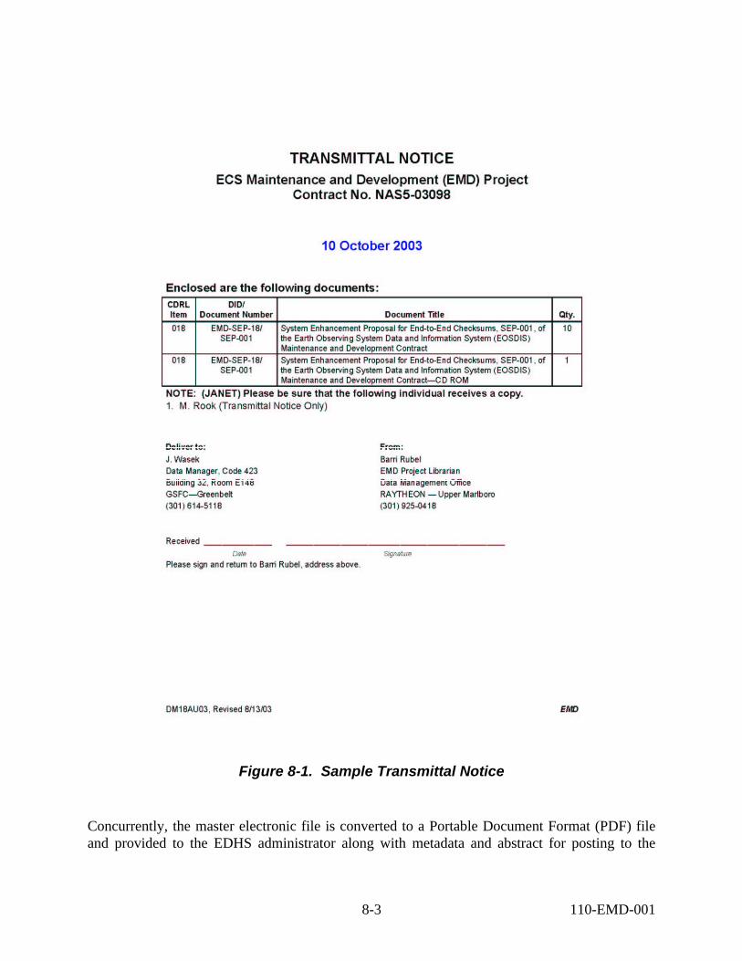
Figure 8-1. Sample Transmittal Notice
Concurrently, the master electronic file is converted to a Portable Document Format (PDF) file and provided to the EDHS administrator along with metadata and abstract for posting to the
8-3 110-EMD-001
EDHS. When the document has been posted to the EDHS, the Administrator logs the load date in the tracking system. This process is directed by project instruction DM-1-014, Distribution of ECS Documentation and Information Using World Wide Web Technology.
8.3.5 Document Archiving
The signed master or “golden” hard copy is submitted to the Documentation Center for archiving. All hard copy masters are stored in a secured room. Copies of non-proprietary and non-project sensitive documents are made available in the library for project staff to borrow.
The master electronic file is compacted (along with any supporting files) and placed on the DMO server for retrieval by the Documentation Center staff. The Documentation Center staff retrieves the compacted file, archives it to a numbered CD-ROM, and logs the archive date and disk number in the tracking system. All archive disks are stored in a fireproof cabinet in the Documentation Center. Once the document is archived, the files are removed from any local hard disks. Further direction is provided in project instruction DM-1-009, Documentation Archiving and Storage.
Electronic document masters can be retrieved for updating by submitting a request (email or voice mail) to the Project Librarian.
8.3.6 Status Reporting
The DMO is responsible for tracking CDRL submittal and delivery dates and will support status reporting in several different ways:
• The DMO maintains and generates a report showing the status of all data items due to the customer. This report is presented to Senior Staff at the beginning of each month. Additionally, this report is included is the Monthly Progress Report (DID EMD-MPR-10).
• In the case of overdue data, the DMO contacts the originator of the late data to determine latest status, reason for late submittal, any problem that management should be aware of, and anticipated new due date. This information is conveyed to management and the status report updated as appropriate.
• A detailed status report can be obtained that lists every CDRL item, submittal date, and responsible organization.
8-4 110-EMD-001

Abbreviations and Acronyms
AI Action Item
API Application Programming Interface
ARB Architecture Review Board
BLM Baseline Management
BOE Basis of Estimate
CCB Configuration Control Board
CCR Configuration Change Request
CDMTS Configuration Data Management Tracking System
CDR Critical Design Review
CDRL Contract Data Requirements List
CM Configuration Management
CMM Capability Maturity Model
CMP Configuration Management Plan
COTS Commercial Off-the-shelf
CPT Cross Product Team
CSCI Computer Software Configuration Item
CSA Configuration Status Accounting
CSG ClearCase™ Support Group
CSR Consent to Ship Review
CUT COTS Upgrade Team
DAAC Distributed Active Archive Center
DBMS Data Base Management System
DCN Document Change Notice
DDTS Distributed Defect Tracking System™
DID Data Item Description
DLOC Delivered Lines of Code
DMO Data Management Office
AB-1 110-EMD-001

DUE DAAC Unique Extension
EBF Emergency Bug Fix
EBIS EMD Baseline Information System
ECM EMD Change Manager
ECO Engineering Change Order
ECS Earth Observing System Data and Information System (EOSDIS) Core System
EDC EROS Data Center
EDF ECS Development Facility
EMD EOSDIS Core System (ECS) Maintenance and Development
EOS Earth Observing System
EOSDIS Earth Observing System Data and Information System
EROS Earth Resources Observation System
ES Engineering Software
ESDIS Earth Science Data and Information System
ESDT Earth Science Data Type
FCA Functional Configuration Audit
GSFC Goddard Space Flight Center
HMDP Hardware Maintenance and Development Plan
ILM Integrated Logistics Management
IPT Integrated Product Team
IRR Incremental Release Review
IV&V Independent Verification and Validation
LaRC Langley Research Center
LLR Lessons Learned Review
MCMR Monthly Contractor Manpower Report
MPP Monthly Patch Plan
MPR Monthly Progress Report
MR Modification Request
MRB Modification Review Board
NASA National Aeronautics and Space Administration
AB-2 110-EMD-001

NCR Non-conformance Report
NSIDC National Snow and Ice Data Center
OSS Operations Support Software
PAR Performance Assurance Requirements
PCA Physical Configuration Audit
PDL Program Design Language
PEB Performance Evaluation Board
PI Project Instruction
PMR Program Management Review
PMT Program Management Team
PRB Problem Review Board
PSR Pre Ship Review
PVC Performance Verification Center
QA Quality Assurance
QAE Quality Assurance Engineer
QMS Quality Management System
RC Risk Coordinator
RI Responsible Individual
RMP Risk Management Plan
ROM Rough Order of Magnitude
RRR Release Readiness Review
RSR Release Status Review
SCM Supply Chain Management –or- Software Configuration Management
SCA Subcontractor Administrator
SCDV Science and Development
SDF Software Development Folder
SDL Software Development Library
SDP Software Development Plan
SDPS Science Data Processing Segment
SEIT System Engineering And Integration Team
AB-3 110-EMD-001
SEL Software Estimation Lead
SEP System Enhancement Proposal
SEPG Software Engineering Process Group
SIT System Integration and Test
SLOC Source Lines of Code
SMC System Monitoring Center
SMDP Software Maintenance Development Plan
SPR Subcontractor Progress Review
SQAP Software Quality Assurance Plan
SRA Site Readiness Assessment
STM Software Turnover Meeting
STTS Software Turnover Tracking System
SWIT Software Integration and Test
TBD To Be Determined
TBR To Be Resolved
TE Test Executable
TPR Task Plan Request
TRR Test Readiness Review
TT Trouble Ticket
UML Unified Modeling Language
VATC Verification and Acceptance Test Center
VDB Verification Database
VDD Version Description Document
WI Work Instruction
AB-4 110-EMD-001