epa of emissions from ink and manufacturing · software, and presentation of ... reduction methods...
TRANSCRIPT

EPA
United States Environmental Protection Agency
Office of Air Quality Planning and Standards Research Triangle Park NC 27711
EPA-450/3-92-013 April 1992
Air
CONTROL OF VOC EMISSIONS FROM INK AND PAINT MANUFACTURING PROCESSES
control technology center


EPA-450/3-92-013
CONTROL OF VOC EMISSIONS FROM INK AND PAINT MANUFACTURING PROCESSES
CONTROL TECHNOLOGY CENTER
SPONSORED BY:
Emission Standards Division Office of Air Quality Planning and Standards
U.S. Environmental Protection Agency Research Triangle Park, North Carolina 27711
Air and Energy Engineering Research Laboratory Office of Research and Development
U.S. Environmental Protection Agency Research Triangle Park, North Carolina 27711
April 1992


EPA-450/3-92-013 April 1992
CONTROL OF VOC EMISSIONS FROM INK AND PAINT MANUFACTURING PROCESSES
Prepared by:
B.W. McMinn P.J. Marsosudiro
Alliance Technologies Corporation 100 Europa Drive, Suite 150
Chapel Hill, North Carolina 27514
EPA Contract No. 68-D0-0121 Work Assignment No. 1-29 (Alliance No. 1-638-029-1)
Project Officer
Joseph Steigerwald Emission Standards Division
U.S. Environmental Protection Agency Research Triangle Park, North Carolina 27711
Prepared for:
Control Technology Center U.S. Environmental Protection Agency
Research Triangle Park, North Carolina 27711
CH-92-02

DISCLAIMER
This final report was prepared for the Control Technology Center, U.S. Environmental
Protection Agency, by Alliance Technologies Corporation, 100 Europa Drive, Chapel Hill, NC
27514, in partial fulfillment of Contract No. 68-D0-0121, Work Assignment No 1-29. The
opinions, findings and conclusions expressed axe those of the authors and not necessarily those
of the Environmental Protection Agency.
CH-92-02 11l

PREFACE
This report was prepared for and funded by the Control Technology Center (CTC), U.S.
Environmental Protection Agency. The CTC was established by EPA's Office of Research and
Development (ORD) and Office of Air Quality Planning and Standards (OAQPS) to provide
technical assistance to State and local air pollution control agencies. Several levels of assistance
are available through the CTC: a CTC HOTLINE provides telephone assistance on matters
relating to air pollution control technology; in-depth engineering assistance is provided when
needed by EPA and its contractors; and the CTC can provide technical guidance through
publication of technical guidance documents, development of personal computer software, and
presentation of workshops on control technology matters. The fourth assistance program
sponsored by the CTC is the CTC Bulletin Board System (BBS), a part of the EPA OAQPS
Technology Transfer Network. Users of the BBS can retrieve CTC information through one of
four major area menu selections. The four areas included are Utilities, Help Center,
Documents/Software, and CTC Projects.
Technical guidance projects, such as this one, focus on topics of national or regional
interest that are identified through contact with State and local agencies. In this case, the CTC
received a number of calls on controlling volatile organic compound (VOC) emissions from
processes used to manufacture ink and paint. Controlling VOC emissions at various source types
that have not been addressed by Control Techniques Guidelines (CTG's) is of interest to many
States and local air pollution control agencies due to on-going ozone nonattainment prob!ems (VOC is a precursor of ozone) and requirements in Title I of the Clean Air Act Amendments of
1990. This report presents the results of a study to identify and collect information on paint and
ink manufacturing processes and the VOC emissions generated during these operations.


TABLE OF CONTENTS
Section Page
Disclaimer 111
Preface iv
List of Tables vm
List of Figures ix
Executive Summary x
1.0 Introduction 1-1
2.0 2.1 2.2
2.3
2.4
2.5
Industry Structure and Process Description 2-1 General 2-1 Paint Manufacturing Industry Structure 2-1 2.2.1 Introduction 2-1 2.2.2 Market, Raw Materials, and Products 2-1 2.2.3 Paint Product End-Uses 2-4 Ink Manufacturing Industry Structure 2-8 2.3.1 Introduction 2-8 2.3.2 Market, Raw Materials, and Products 2-8 2.3.3 Ink Product End-Uses 2-11 Manufacturing Process Description 2-14 2.4.1 Introduction 2-14 2.4.2 Preassembly and Premix 2-14 2.4.3 Pigment Grinding or Milling 2-17 2.4.4 Product Finishing 2-28 2.4.5 Product Filling 2-29 References 2-31
3.0 3.1 3.2
3.3
Volatile Organic Compound Emissions, Regulations, and Pemaits 3-1 General 3-1 Source Identification and Characterization 3-1 3.2.1 3.2.2 3.2.3 3.2.4 3.2.5 3.2.6 Emission
Introduction 3-1 Preassembly and Premix 3-2 Pigment Grinding or Milling 3-2 Product Finishing 3-4 Product Filling 3-4 Equipment Cleaning 3-5 Factor Data 3-6
CH-92-02 V
TABLE OF CONTENTS (continued)
Section Page
3.4
3.3.1 Introduction 3-6 3.3.2 Current Regulations 3-8 3.3.3 Permits 3-9 3.3.4 Plant Trips 3-15 References 3-17
4.0 4.1 4.2
4.3
4.4
4.5
Emission Control Techniques 4-1 Introduction 4-1 Voc Emission Reduction Methods 4-1 4.2.1 Equipment or Process Modifications 4-2
4.2.2 Improved Operating Practices 4-6 4.2.3 Recycling Techniques 4-7 Product Reformulation 4-7 4.3.1 Powder Coatings 4-10 4.3.2 .Waterborne Paints and Inks 4-10 4.3.3 Radiation-Curable Paints and Inks 4-11
4.3.4 High-Solids Paints and Inks 4-11 VOC Emissions Reduction by Control Systems 4-12
4.4.1 4.4.2 4.4.3
Capture Devices 4-12 Recovery Techniques 4-14 Combustion Techniques 4-19
References 4-25
5.0 5.1 5.2
5.3 5.4 5.5 5.6 5.7
Control Cost Analysis 5-1 Introduction 5-1 Thermal Incineration 5-1
5.2.1 Equipment Tank Lids 5-1 5.2.2 Horizontal Media Mills 5-4 5.2.3 Equipment Cleaning Devices 5-6 VOC Emissions Reduction Methods 5-6 Product Reformulation 5-8 Capture Devices 5-8 Thermal Incineration 5-8 References 5-11
CH-92-0Z vi

Section
Appendix A
Appendix B
Appendix C
TABLE OF CONTENTS (continued)
Page
Lists of Facilities with Annual Sales Greater Than $1 Million A-1
Permit Requirements from Several States B-1
Trip Reports C-1
CH-92-02 vii


LIST OF TABLES
Number Page
2-1 2-2 2-3 2-4
Paint Raw Materials Consumed in 1987 2-3 Paint Categories By Use 2-5 Ink Raw Materials Consumed in 1987 2-9 Ink Categories By Use 2-12
3-1
3-2 3-3 3-4
Uncontrolled Emission Factors for Paint, Varnish, and Printing Ink Manufacturing 3-7 State Regulations for Paint and Resin Manufacturing Facilities 3-10 State Regulations for Coatings and Ink Manufacturing Facilities 3-13 Emissions for 1990 3-16
5-1
5-2 5-3 5-4
Applicability and Use of VOC Emission Reduction Methods in Paint and Ink Facilities 5-2 Equipment Cover Cost Figures 5-5 Horizontal Media Mill Cost Figures 5-7 Cleveland: Facility Thermal Incineration Cost Figures 5-10
Paint and Allied Products Facilities (SIC 2851) with Annual Sales Greater Than $1 Million A-2 Printing Ink Facilities (SIC 2893) with Annual Sales Greater Than $1 Million A-14
B-1 B-2 B-3 B-4 B-5
Selection of Ohio Permit Information B-2
State of California Permit Information B-3 State of Illinois Permit Information B-4 State of Texas Permit Information B-7 Permit Information for Other States B-23
CH-92-02 VIII


LIST OF FIGURES
Number Page
2-1 2-2 2-3 2-4a 2-4b 2-5
Flow Diagram of the Paint and Ink Manufacturing Process 2-15 Schematic Diagram of a Three-Roll Mill 2-18 Schematic Drawing of Conventional Sand Mill 2-22 Schematic Drawing of the Stator/Rotor Assembly in a High-Speed Stone Mill 2-24 Schematic Drawing of the Stator/Rotor Assembly in a Colloid Mill 2-24 Schematic Drawing of the Milling Head of a High-Speed Impingement (Kinetic Dispersion Mill) 2-27
4-1 4-2 4-3 4-4 4-5
Typical Flat Mix Tank Cover 4-4
Recycling and Reusing Cleaning Solvent 4-8 Production Trends in Coating Systems 4-9 Catalytic Incinerator 4-20 Thermal Incinerator 4-20


EXECUTIVE SUMMARY
In the United States today there are approximately 1,123 companies operating 1,426 paint
plants and 224 companies operating 504 ink facilities. Many of these manufacturing facilities
produce solvent-based products. Together the two industries consume an estimated 2,750 million
pounds of organic solvent which accounts for 0.05 percent of total volatile organic compound
(VOC) emissions. The application of these paints and inks accounts for an additional 13 percent
of VOC emissions.
The products of the paint manufacturing industry include architectural coatings, product
coatings for original equipment manufacturers (OEM), and special-purpose coatings. The four
primary types of inks are letterpress inks, lithographic and offset inks, gravure inks, and
flexographic inks. All of these products are made with the same basic raw materials: pigments,
solvents, resins (or binders), and other additives. In most cases, the manufacturing facilities
purchase these raW materials and then formulate or blend, rather than react, to produce a finished
product. The batch process production of paint and ink involves four major steps: preassembly
and premix, pigment grinding/milling, product finishing/blending, and product filling/packaging.
Some of the equipment used to accomplish these manufacturing steps include roller mills; ball
and pebble mills; attritors; sand, bead, and shot mills; horizontal media mills; and high-speed disk
dispersers. Releases of volatile organic compounds from paint and ink manufacturing include those
from the process steps and from cleanup operations. However, very little information is available
which quantifies these emissions. Many paint and ink manufacturing facilities calculate total
plant VOC emissions based on raw material consumption rather than calculating emissions from
processes or equipment by an alternative method. Emission values therefore reflect solvent losses
from manufacturing, cleaning, and storage. Because emissions have not been quantified, there
are no publicly available emission factors for paint and ink manufacturing processes. Emission
factor data contained in facility permits is most likely based on theoretical equations rather than
on actual test data. These values vary significantly from State to State.
Similarly, regulatory requirements vary from State to State as paint and ink facilities are
not identified by any current Control Technique Guideline (CTG). In many States only those
non-CTG facilities emitting more than 100 tons per year are controlled,,while in other States the
CI-I-9.2-02 X
VOC limit may be 15 pounds per day. Several of the requirements common to the States with
rules regulating VOC emissions from paint and ink facilities include the following: covers must
be used on all open equipment and equipment must be monitored and inspected regularly for
leaks. Most States also exclude from regulation those facilities emitting less than 100 tons per
year VOC and those plants manufacturing primarily water-based products.
Regardless of State regulations, paint and ink facilities must use some method to control
the VOC emissions that are generated throughout the manufacturing process. If left uncontrolled,
these emissions can cause high concentrations of VOC in the work area compromising worker
health, safety, and productivity. Some of the methods used by paint and ink facilities in reducing
emissions are tank lids, horizontal media mills, equipment cleaning devices, recycling techniques,
and improved operating practices. Many facilities have also invested research and development
time and dollars in new product lines with lower VOC concentrations. Powder coatings,
waterborne paints and inks, radiation-curable paints and i•ks, and high-solids products are slowly
replacing some of the markets once dominated by solvent-borne formulations.
Few facilities use VOC reduction methods other than those previously mentioned.
However, control systems including capture devices and thermal incinerators are technically
feasible for the low VOC concentrations and the wide variety of contaminants found in paint and
ink waste streams.
Before a thorough assessment of control systems can be conducted, more emissions data
must be accumulated or generated. There is a general lack of data presented in literature and
State permit information concerning the quantity, composition, and breakdown of the emissions
generated by the various stages in the paint and ink manufacturing process.

CHAPTER 1
INTRODUCTION
This report presents the results of a study to collect and report information on processes
used to manufacture paint and ink, volatile organic compound (VOC) emissions generated during
these operations, emission control techniques and their effectiveness, and costs associated with
process changes and emission control options. Stat• agencies and other government-sponsored
programs, as well as equipment manufacturers, professional and trade organizations, and paint
and ink manufacturers were contacted to assess production methods, available control
technologies, and current emission rates from the manufacturing processes.
Many paint and ink manufacturing facilities produce solvent-based products. In the United
States today, there are approximately 1,123 companies operating 1,426 paint plants and 224
companies operating 504 ink facilities. Almost half of these plants are small, employing fewer
than 20 people. Most of the facilities are located in population centers because of high
transportation costs. It is also estimated that more than half of these plants are located in ozone
nonattainment areas.
This report is divided into five chapters and three appendices. Chapter 2 characterizes the
two areas of primary focus, the paint manufacturing industry and the ink manufacturing industry,
and also provides a general description of the raw materials these facilities use, the products they
make, and the markets they serve. Chapter 2 also provides a description of the manufacturing
process and processing equipment common to both ink and paint manufacturers.
The sources of process VOC emissions are identified and characterized in Chapter 3. Also
included in this section are emission factor data which are divided into three sections:
information retrieved from current State regulations, information obtained from State permit files,
and data received from plant trips. Chapter 4 discusses methods of reducing and controlling VOC emissions resulting from the
ink and paint manufacturing process. Areas addressed include equipment and process
modifications, improved operating practices, recycling techniques, product reformulations, and
add-on control techniques. Chapter 5 estimates the costs associated with several of these
reduction and control methods.
c•-gz-0z 1-1

The report also includes three appendices. Appendix A lists paint and ink facilities with
annual sales greater than one million dollars. Appendix B contains tables which have a selection
of permit requirements from several States. Appendix C contains copies of the trip reports for
the two paint and two ink facilities visited during the course of this work assignment.
ca-gz-o• 1-2

CHAPTER 2
INDUSTRY STRUCTURE AND PROCESS DESCRIPTION
2.1 GENERAL
This chapter gives an overview of the paint and ink manufacturing industries. The chapter
is divided into three sections: Paint Manufacturing Industry Structure, Ink Manufacturing
Industry Structure, and Manufacturing Process Description. Both of the industry structure
sections address the current market, materials used in the manufacturing process, products
manufactured, and product end-uses. The last section in this chapter focuses on the four steps
in both the paint and ink manufacturing processes with emphasis on equipment and procedure.
2.2 PAINT MANUFACTURING INDUSTRY STRUCTURE
2.2.1 Introduction
This section gives an overview of the paint manufacturing industry, including geographic
distributions, production trends, industry issues, and the major subdivisions within the industry.
Also included in this section is information relating to manufacturing raw materials, finished
products, and product end-uses. Much of the data is based on the Standard Industrial
Classification (SIC) 2851.
2.2.2 Market, Raw Materials, and Products
The paints and allied products industry, as def'med by SIC 2851, consists of firms that
manufacture paints, varnishes, lacquers, enamels, shellacs, putties, wood fillers and sealers, paint
and varnish removers, paint brush cleaners, and allied paint products. Facilities which
manufacture pigments, resins, printing inks, adhesives and sealants, and artists' paints are not
included under SIC code 2851. According to the 1987 Census of Manufactures, the paints and
allied products industry employed 55.2 thousand people with nearly 40 percent of the industry's
employment in the States of California, Ohio, Illinois, and New Jersey. In 1987, SIC 2851
cn-92-02 2-1

facilities were composed of 1,123 companies operating 1,426 plants, two-thirds of which were
located in ten states. Over 50 percent of paint manufacturing plants are •mall, privately owned
facilities employing less than 20 people and specializing in a limited product line marketed within
a small geographic region. Some companies, however, own multiple manufacturing facilities and
distribute products nationwide. Regardless of ownership, the paint manufacturing industry tends
to concentrate in population centers because of high transportation costs. An estimated 50
percent of the manufacturing facilities are located in ozone nonattainment areas. 1
The raw materials used in the paint manufacturing process include pigments, solvents, and
resins. Some commonly used paint raw materials are listed in Table 2-1. The chemical
composition of paint varies depending on the desired paint properties. Pigments provide the
coating with color, opacity, and a degree of durability. Pigmented coatings are more weather-
resistant than unpigmented paints. In the case of metal primers, pigments are used to check or
inhibit corrosion of the metal. Pigments may be either organic or inorganic. Almost all of the
organic pigments used today are manufactured, while inorganic pigments may be either natural
or manufactured. Most natural pigments are oxides or hydroxides of iron. Manufactured
pigments span the entire color spectrum with a wide range of brilliance and opacity. 2
The fluid component of a coating, consisting of nonvolatile binders and volatile solvents,
is called the vehicle. Binders are those components which form a continuous phase, hold the
pigment in the dry film, and cause it to adhere to the surface to be coated. The majority of
binders in modern paint films are composed of resins and drying oils which are largely
responsible for the protective and general mechanical properties of the film. Most resins and oils
used in paint manufacturing are organic, although some are inorganic. Alkyds, acrylics, and
vinyls are three of the more commonly used resins. 2'3
The vehicle solvents are used to keep paints in liquid form so they can be applied easily.
When a coating is deposited on a substrate, the solvent should evaporate completely. It is used
to transfer the pigment/binder mixture to a surface in a thin, uniform film and plays no role in
film formation. Materials used as solvents include aliphatic hydrocarbons (white spirit and the
Special Boiling Point (SBP) solvents), aromatic hydrocarbons (toluene, xylene, and the trimethyl
benzenes), alcohols, esters, ketones, esters and ether-esters of propylene glycol. Water is the
solvent in water based and emulsion paints. 2'3
ca-9•-o• 2-2

TABLE 2-1. PAINT RAW MATERIALS CONSUMED IN 1987
Material Quantity 1
Vegetable oils mil lb "183.0
Pigments: Titanium dioxide, composite and pure (100% TiO2) mil lb Other inorganic pigments, including chrome colors, whiting,
white and red lead, litharge, lithopone, zinc oxide, calcium carbonate precipitated, etc
Organic color pigments, lakes, and toners
Solvents: Hydrocarbons (toluene, xylene, etc.) rail lb Alcohols (butyl, ethyl, isopropyl, etc.) do Ketones and esters (methyl ethyl ketone, ethyl acetate,
etc.) do Other do
Plastics resins: Alkyds mil lb Acrylics do Vinyl do Other plastics resins do
Petroleum thinners (naphtha) mil gal
Nonmetallic minerals and earths, ground or otherwise treated (calcium carbonate, talc, silica, kaolin, mica, barite, soapstone, clay, and other clay minerals) for use as extenders
All other organic and inorganic chemicals, n.e.c
763.7
(NA) ONA)
435.2 *382.5
*626.3 627.9
**595.0 *764.5
(s)
1For some establishments, data have been estimated from central unit values which are based on quantity-cost
relationships of the data reported by the establishment. The following symbols are used when the percentage of each quantity figure estimated in this manner equals or exceeds 10 percent of the figure published in this
table: *10 to 19 percent estimated; **20 to 29 percent estimated. If 30 percent or more is estimated, figure is replaced by (S).
Source: Adapted from Reference do Ditto
n.e.c. Not elsewhere classified (NA) Not available (S) Withhdd because estimate did not meet publication standards
ca-92-02 2-3

Another category of paint raw materials, present only in small concentrations in the 0.2 to
ten percent range, is additives. These chemicals perform a special function or impart a certain
property to the coating. Additives include driers, thickeners, biocides, surfactants, dispersing
agents, antifoams, and catalysts. 3
The products of the paint manufacturing industry are categorized according to their use, the
type of vehicle or carrier used in manufacture, and the method of curing. The use categories are
architectural coatings, product coatings for original equipment manufacturers (OEM), and special
purpose coatings. 4 Architectural coatings are products used to coat interior and exterior surfaces.
OEM coatings include finishes which provide the first coating on newly manufactured equipment
and products. Special purpose coatings are products formulated to meet specific use requirements
such as extreme temperatures or heavy wear. A summary of the paint use divisions by use
category and subcategory is found in Table 2-2. In 1987, the value of all coating shipments was
$9.91 billion dollars ($4.25 billion for architectural coatings, $3.64 billion for product coatings,
and $2.02 billion:for special purpose coatings). 1 Ward's Business Directory lists 364 paint and
allied products facilities in SIC 2851 with 1990 sales greater than $1,000,000. This list is given
in Appendix A, Table A-1.5
Paint products may also be classified by the type of vehicle or carrier incorporated in the
paint formulation. This classification normally refers to the volatile solvent portion of the vehicle
rather than to the combined solvent and binder. The volatiles, typically water or solvent,
evaporate after the paint has been applied to the substrate. The total annual production of the
average paint plant in the United States consists of 60 percent solvent based product, 35 percent
water based paint, and 5 percent allied products. While more than 70 percent of architectural
coatings are water based, the majority of product and special purpose coatings are solvent based,
The third method used to categorize coatings is curing. This system applies to nonvolatile
coating systems which do not rely on the evaporation of solvent or water to achieve the desired
finish. Coatings included in this category are powder coatings, radiation-curable coatings, and
two-part catalyzed paints.
cn-92-0z 2-4

TABLE 2-2. PAINT CATEGORIES BY USE
Product
1987 Product Shipments
Quantity Value
(million dollars)
ARCHITECTURAL COATINGS mil gal
Exterior, solvent-type: Solvent thinned painm and tinting bases, including
barn and roof paints rail gal Solvent thinned enamels and tinting bases,
including interior-exterior floor enamels do Solvent thinned undercoaters and primers do Solvent thinned clear finishes do Solvent thinned stains, including shingle and
shake do Other exterior solvent thinned coatings, including
bituminous paints do
Exterior, water-type: Water thinned paints and tinting bases, including
barn and roof paints mil Water thinned undercoaters and primers do
Water thinned stains do Other exterior water thinned coatings do
Interior, solvent-type: Flat solvent thinned wall paints and tinting
bases, including mill white paints rail gal Gloss and quick drying enamels and other gloss
solvent thinned paints and enamels do Semigloss, eggshell, satin solvent thinned
paints, and tinting bases do Solvent thinned undercoaters and primers do Solvent thinned clear finishes do Solvent thinned stains do Other interior solvent thinned coatings do
Interior, water-type: Flat water thinned paints and tinting bases mil gal Semigloss, eggshell, satin, and other gloss
water thinned paints and tinting bases do Water thinned undercoaters and primers do Other Interior water thinned coatings do
527.0
20.2
14.5 8.2
10.3
17.8
11.6
95.9 7.7 9.2
11.4
8.3
4.4
15.0 7.0 8.6 7.6 5.8
125.5
81.3 10.2 15.9
4,245.4
216.5
152.7 78.3 83.6
165.4
120.3
732.0 58.7 61.9
100.1
81.5
53.6
155.7 64.3
100.7 83.7 63.6
834.3
614.1 64.9
106.8
Architectural lacquers do
Architectural coatings, n.s.k do
10.5
19.9
81.7
170.9
(continued)
ca-gz-oz 2-5

TABLE 2-2. PAINT CATEGORIES BY USE (continued)
Product
1987 Product Shipments
Quantity Value
(million dollars)
PRODUCT FINISHES FOR ORIGINAL EQUIPMENT MANUFACTURERS (OEM), EXCLUDING MARINE COATINGS rail gal
Automobile finishes do
Truck, bus, and recreational vehicle finishes do
Other transportation equipment finishes, including aircraft and railroad do
Appliances, heating equipment, and air-conditioner finishes do
Wood furniture, cabinet, and f'Lxture finishes do
Wood and composition board fiat stock finishes do
Sheet, suip, and coil coatings, including siding do
Container and closure finishes do
Machinery and equipment finishes, including road building equipment and farm implement do
Nonwood furniture and fixture finishes, including business equipment finishes do
Paper, paperboard, film, and foil finishes, excluding pigment binders do
Electrical insulating coatings do
Powder coatings do
Other industrial product f-mishes, excluding semimanufactured products, such as pigment dispersions and ink vehicles do
Product finishes for original equipment manufacturers (OEM), excluding marine coatings, n.s.k do
SPECIAL PURPOSE COATINGS, INCLUDING ALL MARINE COATINGS rail gal
Industrial new consmaction and maintenance paints (especially formulated coating for special conditions of industrial plants and/or facilities requiring protection against extreme temperatures, fungi, chemicals, fumes, etc.):
Interior do Exterior do
327.1
55.4 14.9
3.2
5.8 43.1 7.3
20.3 60.2
16.2
14.3
11.0 3.6
19.1
27.6
24.9
137.3
13.0 28.5
3,637.0
987.7 280.3
54.3
70.1 276.6 53.2
303.4 413.1
181.3
187.7
66.7 34.1
193.2
333.0
202.4
2,018.6
169.8 323.6
(continued)
2-6

TABLE 2-2. PAINT CATEGORIES BY USE (continued)
1987 Product Shipments
Product Quantity Value
(million dollars)
SPECIAL PURPOSE COATINGS, INCLUDING ALL MARINE COATINGS, Continued
Traffic marking paints (all types, shelf goods, and highway department) do 19.8
Automotive, other wansportation, and machinery ref'mish paints and enamels, including primers do 44.3
Marine paints, ship and offshore facilities and shelf goods for both new construction and marine refinish and maintenance, excluding spar varnish do 9.1
Aerosol-paint concenwates produced for packaging in aerosol containers do 12.8
Special purpose coatings, n.s.k do 9.9
98.7
903.8
144.1
239.8 138.9
•In 1987, quantity was collected in pounds and converted to gallons using a conversion factor of 3 Ib:l gal.
Source: Adapted from Reference 1
do Ditto n.s.k. Not specified by kind
ca-9"z-oz 2-7
2.2.3 Paint Product End-Uses
Paint is a suspension of finely separated pigment particles in a liquid, which when spread
over a surface in a thin layer will form a solid, cohesive, and adherent film. Paints have been
used for many centuries for decorative purposes. The Industrial Revolution expanded the end-
uses of paint and can be thought of as the beginning of the modern paint industry. 2 Today,
paints are used to solve both aesthetic and protective problems on a variety of surfaces which
include wood, masonry, metal, plastics, and fiberglass. The end-uses of paint are defined by the
markets served (See Table 2-2).
2.3 INK MANUFACTURING INDUSTRY STRUCTURE
2.3.1 Introductibn
This section gives an overview of the ink manufacturing industry, including geographic
distributions, production trends, industry issues, and the major subdivisions within the industry.
Also included in this section is information relating to manufacturing raw materials, finished
products, and product end-uses. Much of the data is based on the Standard Industrial
Classification (SIC) 2893.
2.3.2 Market, Raw Materials, and Products
The ink manufacturing industry includes those facilities classified under SIC code 2893
which manufacture letterpress, lithographic and offset inks, gravure, and flexographic inks. This
category does not include the addition of solvents to inks by printers to reduce ink viscosity (i.e.,
press side reduction). The 1987 Census of Manufactures shows that the 504 ink manufacturing
facilities in the United States are owned by 224 companies which employ a total of 11,100
people in nineteen States and the District of Columbia. More than 60 percent of the
manufacturing facilities employ fewer than 20 people. 6 Like paint manufacturing facilities, ink
CH-92-02 2-8
plants concentrate in population centers. Nearly 60 percent of all ink facilities and 75 percent
of all persons employed by ink facilities are located in ozone nonattainment areas. 6
Printing inks are a mixture of pigments, oils, resins, solvents, and driers. Some commonly
used ink raw materials are listed in Table 2-3. The fluid component of the ink, made of binders
(oils and resins) and solvents, is called the vehicle. The vehicle serves as the dispersing and
carrying agent for the pigment particles and gives the ink the required rheological properties of
flow and plasticity. Vehicles carry pigments through printing presses and transfer and bind the
ink to the surface to be printed. 7'8
Pigments are the solid, colored part of printing inks which are visible to the eye when
viewing printed material. As in paints, pigments provide inks with color, opacity, durability, and
body or consistency. Pigments, as well as binders, determine whether or not a print will bleed
in water, oil, alcohol, fats, acid, or alkali. Thus, pigments are partially responsible for
determining the end use of the ink. Ink pigments, like paint pigments, may be classified as either
organic or inorganic and natural or manufactured. 7'8
Oils serve as one of the film-forming agents in letterpress, lithographic, and offset inks.
Most oils used in the manufacture of printing inks are classified by their origin as mineral oils,
vegetable oils, animal oils, and synthetic oils. Vegetable oils are further categorized into the
drying oils and the non-drying oils. Non-drying oils are used in vehicles which dry by the
absorption of the vehicle into the paper. These oils penetrate the substrate, soft absorbent papers
such as news and comic paper, rather than evaporate from the substrate's surface. Drying oils
dry by oxidation. 8 Vegetable drying oils are most often used in printing inks. The primary
vegetable drying oils are linseed oil, chinawood oil, perilla oil, and soya bean oil. Steadily
replacing the natural oils are synthetic oils such as dehydrated castor oil, re-estefified fish oil
acids, and long-oil alkyds. 7
Resins are one of the primary components in printing ink vehicles. Along with oils, they
serve as film-forming ingredients (binders) and impart to the ink gloss, drying speed, improved
hardness, toughness, and scuff-resistance. Resins are divided into two classes: natural resins and
synthetic resins. All natural resins, with the exception of shellac, are formed by solidifying the
viscous sap of trees. Fresh sap contains both resins and volatile oils. Although the oils are
normally removed by distillation or evaporation, residual volafiles may remain in the treated resin
and eventually contribute to the volatile content of the ink product.. Several synthetic resins
CH-92-02 2-9

TABLE 2-3. INK RAW MATERIALS CONSUMED IN 1987
Material Quantity I
Materials, containers, and supplies
Organic and inorganic pigments rail lb
Carbon black do
Plastics resins consumed in the form of granules, pellets, powders, liquids, etc., but excluding sheets, rods, robes, and shapes do
Paints, varnishes, lacquers, shellacs, japans, enamels, and allied products (includes all ink vehicles and varnishes) 1,000 lb
Wood rosin, turpentine, and other wood chemicals mil lb
Hydrocarbon oils and solvents mil gal
Oxygenated solvents do
Metal containers
All other materials and components, parts, containers, and supplies
Materials, containers, and supplies, n.s.k. 2
(NA)
228.6
*283.0
*60.7
*457.6
85.1
**92.7
**24.9
(NA)
(N,•)
IFor some establishments, data have been estimated from central unit values which are based on quantity-cost
relationships of the data repeBed by the establishment. The following symbols are used when the percentage of each quantity figure estimated in this manner equals or exceeds 10 percent of the figure published in this
table: *10 to 19 percent estimated; **20 to 29 percent estimated. If 30 percent or more is estimated, figure is replaced by (S). 2Total
cost of matetials of establishments that did not report detailed matetials data, including establishments that were not mailed a form.
Source: Adapted from Reference 6
do Diuo n.s.k. Not specified by kind (NA) Not available
CH-92-02 2-1 0
include phenol formaldehyde resins, alkyds, polyesters, vinyls, silicones, and polyurethanes. 7
The ink industry refers to solvents as any organic liquid used to dissolve film-forming
materials and keep them in solution until the ink is applied to the surface to be printed. When
the ink has been applied, the solvent should be removed quickly to allow the ink to dry. Ink
formulators use a number of different solvents including ketones, ethers, esters, alcohols, alcohol-
ethers, chlorinated compounds (methylene chloride, carbon tetrachloride, and trichloroethylene),
and some aromatic hydrocarbons such as toluene and xylene. 7
Driers are used in inks which contain oxidizable oils or vehicles which form films by
oxidation. The driers, most often organic salts of metals such as lead, manganese, and cobalt,
act as catalysts and are added to drying oils to increase their normal drying rate. The metal
constituent imparts the drying action, while the organic portion of the salt carries the metal into
solution, or dispersion, with the oil. Too much drier causes the ink to skin and dry on the press,
fill in halftones, and causes the sheets to stick and offset in the pile. 7'8
Inks, like paints, may contain small concentrations of additives. Additives perform a
special function or impart a certain property to the coating. Additives include biocides,
surfactants, antifoams, and waxy or greasy components. The waxy and greasy components are
used to improve the working and setting qualities of the ink, and to eliminate offsetting, sticking,
and picking problems. Waxes may be cooked directly into the vehicle, or prepared as a
compound and added to the ink. 7'8
Inks may also be classified by use and according to the type of vehicle used in the
formulation. The four primary types of inks are letterpress inks, lithographic and offset inks,
gravure inks, and flexographic inks. Typically, flexographic and rotogravure inks employ a
solvent carrier, while letterpress, lithographic, and offset inks are of an oil or paste base. A
summary of the ink classifications by use category and subcategory is found in Table 2-4. In
1987, the value of all ink shipments was $2.36 billion dollars ($164.1 million for letterpress inks,
$987.3 million for lithographic and offset inks, $414.5 million for gravure inks, $424.8 million
for flexographic inks and $370.1 million for otherwise classified inks). 6 Ward's Business
Directory lists 56 ink manufacturing facilities in SIC 2893 with 1990 sales greater than
$1,000,000. This list is given in Appendix A, Table A-2. 5
CH-92o02 2-11

TABLE 2-4. INK CATEGORIES BY USE
Product
1987 Product Shi!•ments Value
Quantity • (million dollars) TOTAL (NA)
Letterpress inks (NA) New inks rail lb 203.1 Publication inks do (S) Packaging inks do 12.1 Other letterpress inks do 16.5 Letterpress inks, n.s.k (NA)
Lithographic and offset inks (NA) News inks rail lb 314.3 Publication inks:
Web types mil lb "179.9 Sheet types do **20.0
Packaging inks do 18.2 Web commercial type do 39.3 Other lithographic and offset inks, including sheet
commercial type mil lb *50.8 Lithographic and offset inks, n.sak (NA)
Gravure inks (NA) Packaging inks rail lb 111.3 Publication inks do 293.8 Other gravure inks do *0.9 Gravure inks, n.s.k (VIA)
Flexographic inks (NA) Packaging inks:
Solvent types rail lb 117.7 Water types do 125.0
Other flexographic inks: Solvent types mil lb 5.2 Water types do 19.8
Flexographic inks, n.s.k (NA) Printing inks, n.e.c (NA)
Textile printing inks rail Ib 36.0 Screen printing inks do (S) Other printing inks, including stencil inks do (S) Printing inks, n.e.c., n.s.k (NA)
Printing ink, n.s.k (NA) Printing inks, n.s.k., typically for establishments with
10 employees or more (see note) (NA) Printing inks, n.s.k., typically for establishments with less
than 10 employees (see note) (NA)
2.360.7 164.1 100.7
9.8 27.4 20.9 5.2
987.3 256.9
311.0 68.5 77.7 73.0
162.8 37.4
414.5 153.6 248.2
1.4 11.2
424.8
189.3 172.4
8.9 31.0 23.1
140.4 45.3 59.6 34.0
1.4 229.7
160.5
69.2
•Data reported by all producers, not just those with shipments of $100,000 or more.
2For some establishments, dam have been estimated from central unit values which are based on quantity-cost
relationships of the dala reported by the establishment. The following symbols are used when the percentage of each qt•ntity figure estimated in this manner equals or exceeds 10 percent of the figure published in this
table: 10 to 19 percent estimamd; **20 to 29 percent estimaled, l.f 30 percent or more is estimated, figure is replaced by (S).
Source: Adapted from Reference 6 do Ditto
n.e.c. Not elsewhere classified n.s.k. Not specified by kind (NA) Not available (S) Withheld because estimat, did not meet publication standards
cu-9"z-0z 2-12

2.3.3 Ink Product End-Uses
The end-uses of ink correspond to the use categories (i.e., the type of printing process for
which the ink is manufactured): letterpress inks, lithographic and offset inks, gravure inks, and
flexographic inks. Letterpress, relief, or typographic inks (except flexographic inks) are those
inks used in printing processes employing raised characters or plates. Letterpress printing is the
oldest printing method, and until the mid 1970s, it was the major consumer of printing inks.
Now, ink facilities manufacture more of both gravure and lithographic inks. The primary uses
of letterpress inks include high-speed, long-run magazine and newspaper printing. Other
letterpress inks are used in the packaging industry, particularly on corrugated containers. Many
letterpress inks are black: almost all black inks use carbon black as the pigmenting agent. 7'8
The majority of letterpress inks dry by absorption or penetration and are, therefore, oil based. 6'7
According to the 1987 Census, lithographic ink accounts for almost 40 percent of ink
shipments in the United States and slightly over 40 percent of product shipment value. 6
Lithographic printing processes include all processes of printing from flat, or slightly etched,
surfaces, such as stone lithography, offset lithography, dry offset printing, and offset tin printing. 7
Lithographic inks are used in the newspaper, publication, and packaging industries. 6 The vehicle
in lithographic inks normally consists of one or more lithographic varnishes (linseed oil that has
been bodied by heat alone) or high-boiling solvents combined with oils and resins. 7'8
Gravure inks, and the gravure processes, are used in the production of fine, engraved
stationery and announcements, postage stamps, paper money, and illustrations in some books.
Gravure printing is also used in newspaper, magazine, and booklet supplements, and on a wide
range of packaging materials such as plastic films and foil. Ink is transferred from an etched fiat
or cylindrical plate to the stock. Gravure inks consist of pigments, binders, and solvents. The
solvents incorporated in gravure inks are very volatile, allowing them to evaporate completely
from the ink f'flm. The most important branches of gravure printing are the copper and steel plate
processes, the steel die stamping process, and the photogravure and rotary photogravure
(rotogravure) processes. 7'8
CH-92-02 2-1 3

Flexography, a branch of rotary letterpress printing, uses flexible, rubber relief plates with
fluid, volatile inks. As of 1987, water has acted as the solvent in slightly more than 50 percent
of flexographic inks. 6 The remaining inks use volatile alcohols and glycol ethers. 6'7 The
flexographic printing process was developed in Germany in the 1920s primarily for printing
grocery bags during their manufacture. Since that time, flexography has spread to other
packaging areas and has been adapted to print on cellophane, foil, Mylar, polystyrene, and
polyethylene. Flexographic inks also print well on glassine, tissue, sulphite, kraft and other paper
stocks, paperboard, corrugated liners, bags, paper labels, box coverings, folding cartons, gift and
trademark wrappings, corrugated boxes, paper cups and containers. Flexographic printing
provides attractive, economical packaging materials and is seen in all grocery stores on
prepackaged items from snack foods to clothing, cigarettes, toiletries, and industrial products. 7'8'9
In addition to the conventional inks (i.e., letterpress inks, lithographic and offset inks,
gravure inks, and flexographic inks), there are several other types of specialty ink products
including textile and silk screen inks, invisible inks, powdered inks, and carbon paper, typewriter,
and duplicating inks.
2.4 MANUFACTURING PROCESS DESCRIPTION
2.4.1 Introduction
Paint and ink facilities use similar manufacturing processes to produce their respective
products. Most small plants (i.e., facilities employing less than 20 people) produce paint in 10
to 500 gallon batches, while larger facilities produce paint in 200 to 3,000 gallon batches with
stock items made in 10,000 gallon runs. 10'11 Inks are produced in batches ranging from one
gallon to over 1000 gallons. 11
The raw materials used in the manufacture of paints and inks include pigments, solvents,
resins (or binders), and other additives. In most cases, the manufacturing facilities purchase these
raw materials and then formulate, or blend, a finished product. Normally, no chemical reactions
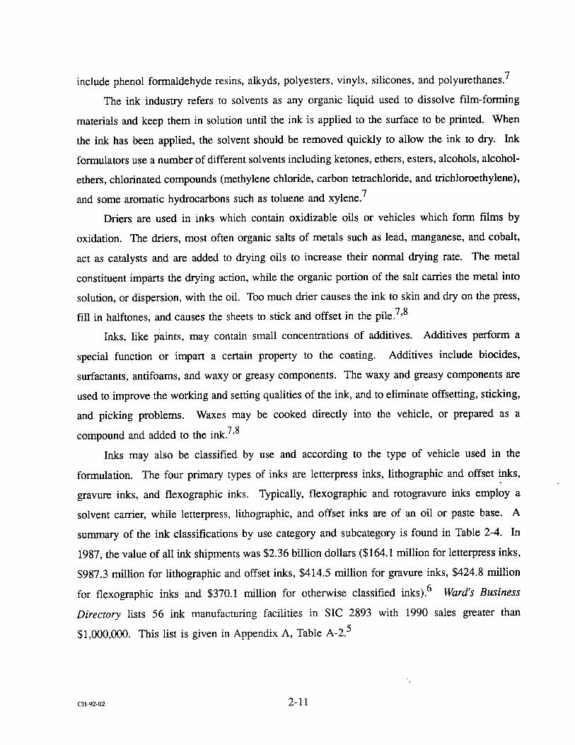
take place during the process. 11 Batch process production of paint and ink involves four major
steps:9,12,13,14 preassembly and premix
CH-92-02 2-1 4

pigment grinding/milling product finishing/blending product filling/packaging
The manufacturing process is summarized in Figure 2-1.
2.4.2 Preassembly and Premix
The first step in the manufacturing process is preassembly and premix. In this step, the
liquid raw materials (e.g., resins, solvents, oils, alcohols, and/or water) are "assembled" and
mixed in containers to form a viscous material to which pigments are added. The pigment and
liquid mixture forms a thicker material, which is then sent to the grinding operations. At this
stage, the particles in the concentrate are rather large (250 pm) and not consistently mixed. 9 The
premix stage results in the formation of an intermediate product which is referred to as the base
or mill base. Wi•h further processing, this base with high pigment concentration may become
any one of a variety of specific end products. 9'12
2.4.2.1 Resin production and cooking
Resin production is typically considered the first step in the manufacturing process.
However, few paint facilities, and even fewer ink plants, currently manufacture their own resins.
This step is now being accomplished in closed reactors in chemical plants. Once the resin has
been manufactured, it must be cooked and then converted to a usable vehicle. Over the last
decade, this step, like resin production, has become increasingly performed by chemical plants.
Chemical facilities cook resins with oils, fatty acids, or alcohols in indirectly heated, closed
stainless steel vessels. 15 These reactors are normally vented through a fractional distillation
column and a condenser, so that vaporized compounds are recycled back into the reactor. After
the resin has .been cooked and then cooled, it is thinned with solvent to produce the vehicle. 15'16
The thinning stage is often the point at which paint and ink plants begin their manufacturing
process.
CH-92-02 2-15
IIII
llll
u!saa • •o•U•l
SaA!•!ppv
•Ua^lO S
uFa • •uaw•!g
2-16

2.4.2.2 Equipment selection
Premixing is necessary to keep the pigment in suspension in the resin, alcohol, solvent, and
oil mixture and to supply the dispersion equipment with a consistently mixed material. A wide
variety of equipment may be used in the premix process. Choosing which to use depends in part
on batch size. Drum-sized batches made in the drum itself may be blended with a portable mixer
which clamps onto the rim of the drum. These mixers normally have a three or four blade
impeller and may be either hydraulic or electric. 17 Other materials made in portable mix tanks
may be blended using larger, permanent high-speed dispersers or variable-speed mixers fitted
with paddle, propellor, turbine, or disc-type agitators. 16 In some cases, a paint or ink will be
moved to a dispersion mill for grinding and milling, and then transferred back to the same premix
mixer for blending operations. 9
Other facilities use typical grinding equipment to accomplish premix operations. One paint
manufacturing plaint uses dispersers and mixers to achieve high-sheared mixing when working
with insoluble powders (i.e., pigments and additives). The same plant uses ball/pebble mills or
Kady mills when mixing soluble powders. In this case, the facility may eliminate the need to
transfer the material to another type of grinding equipment as the premix and milling steps are
accomplished in one piece of equipment. 13
2.4.3 Pigment Grinding or Milling
The incorporation of the pigment into the paint or ink vehicle to yield a fine particle dispersion is referred to as pigment grinding or milling. This process occurs in three stages (i.e.,
wetting, grinding, and dispersion) which may overlap in any grinding operation. To wet the
pigment particles, the wetting agent, normally a surfactant, must displace all contaminants (e.g.,
air, moisture, and gases) adsorbed on the surface of the pigment particles. The wetting process
actually begins in the premix step, when the pigment is charged to the liquid vehicle. 16'18
Grinding is the mechanical breakup and separation of the pigment particle clusters into isolated
primary particles. Dispersion is the movement of the wetted particles into the body of the liquid
vehicle to produce a permanent particle separation. 18
CH-92-02 2 17

The goal of pigment grinding is to achieve fine, uniformly-ground, smooth, round pigment
particles which are permanently separated from other pigment particles. The degree to which this
is realized determines the coating effectiveness and permanency of the paint or ink. Grinding
equipment must work effectively with the vehicle to accomplish this end. Just as there is a
variety of pigment vehicles, so there is an array of dispersion (milling) equipment. Some of the
more common equipment is described in the following nine sections.
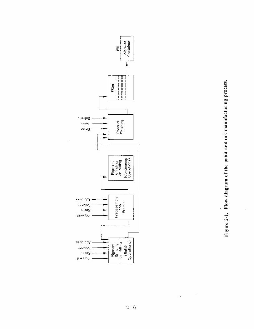
2.4.3.1 Roller mills
Roller mills may have from one to five rolls which grind pigments into vehicles. Most
paint and ink facilities that use roller mills operate with conventional three-roll mills. A
schematic diagram of a three-roll mill is shown in Figure 2-2. The premixed pigmented paste
is charged to the space between the feed and center rolls called the feed bank. End plates
prevent the material in the feed bank from spilling out the sides. The mill base is carried into
the feed nip region by the inward rotation of the feed and center rolls which are turning at
different speeds. Some of the material remains in the feed bank while another portion transfers
through the feed nip to the underside of the roils. Here the material splits. Part transfers to the
center roll while the remaining portion stays on the feed roll to return to the feed bank. The
material that was transferred to the center roll passes through the apron nip, after which a second
split takes place. One amount remains with the center roll, returning to the feed nip, while the
other transfers to the apron roll where it is removed from the roller mill by the takeoff apron.
As the material moves through both the feed and apron nips, it is subjected to very high shear.
This shearing action serves to disperse the pigment throughout the vehicle, while the nip space
determines the degre e of this dispersion. 2'16'18
Roller mills are labor intensive, requiring highly skilled operators. Their lack of speed and
high operating cost make them unsuitable for large-volume production. The use of roller mills
is confined to the manufacture of very high-quality paints and inks and viscous pigmented
products which require fine dispersion and clean color. 16
2.4.3.2 Ball and pebble mills
Ball and pebble mills, probably the oldest pigment dispersion equipment, are cylindrical
containers mounted horizontally and partially filled with either pebbles or ceramic, glass, or
CIt-92-02 2-1 8
2-19

metallic bails which serve as the grinding media. Paint and ink components, either in raw
material or in premix form, are charged to the mill through a top chute. The ball mill and its
contents then rotate about the horizontal axis at a rate sufficient to lift the grinding media to one
side and then cause them to cascade to the lower side. The tumbling action results in pigment dispersion.2,16,18
Ball and pebble mills are distinguished only by their interior lining and grinding media.
The paint and ink industries conventionally define pebble mills as those mills containing a
nonmetallic grinding media such as ceramic, porcelain, silica balls and flint pebbles, and having
an inside surface lined with a nonmetallic liner such as burrstone, porcelain block, or rubber.
Ball mills, on the other hand, contain steel, alumina, iron, or nickel balls and have an interior
surface of alloy steel or another metallic liner. Because of these minor differences, the terms
"ball mill" and "pebble mill" are used rather loosely and the former is often used to describe both
types of mills. 2'16'18
The size mad type of the grinding media will determine the type of paint or ink
manufactured. Small, dense grinding media tend to be more efficient at dispersing pigment than
larger, more porous media. Steel-lined mills charged with steel balls can be used only for dark
colors, as erosion results in the discoloration of whites and pale shades. Normally, lighter colors
are made in pebble mills using ceramic media. 2'16'18
Ball mills offer paint and ink manufacturers the following advantages:
Normally no product premixing is required. The vehicle is often charged directly to
the mill followed by the pigment charge. This offers an economic advantage as
many grinding processes require premixing. 18
The milling process does not require skilled attention or supervision, yielding minimal labor costs. Ball mills can operate on a timer, thus completing the
dispersion orocess outside of normal working hours (i.e., at night or on weekends).K13,18
Low maintenance costs. 18
Ball mills are adaptable to the grinding of most paint dispersions and of all pigments. Only highly viscous products are not amenable to ball mill grinding. 18
Ball mills offer product standardization and consistency. 18
cH-92-02 2-20
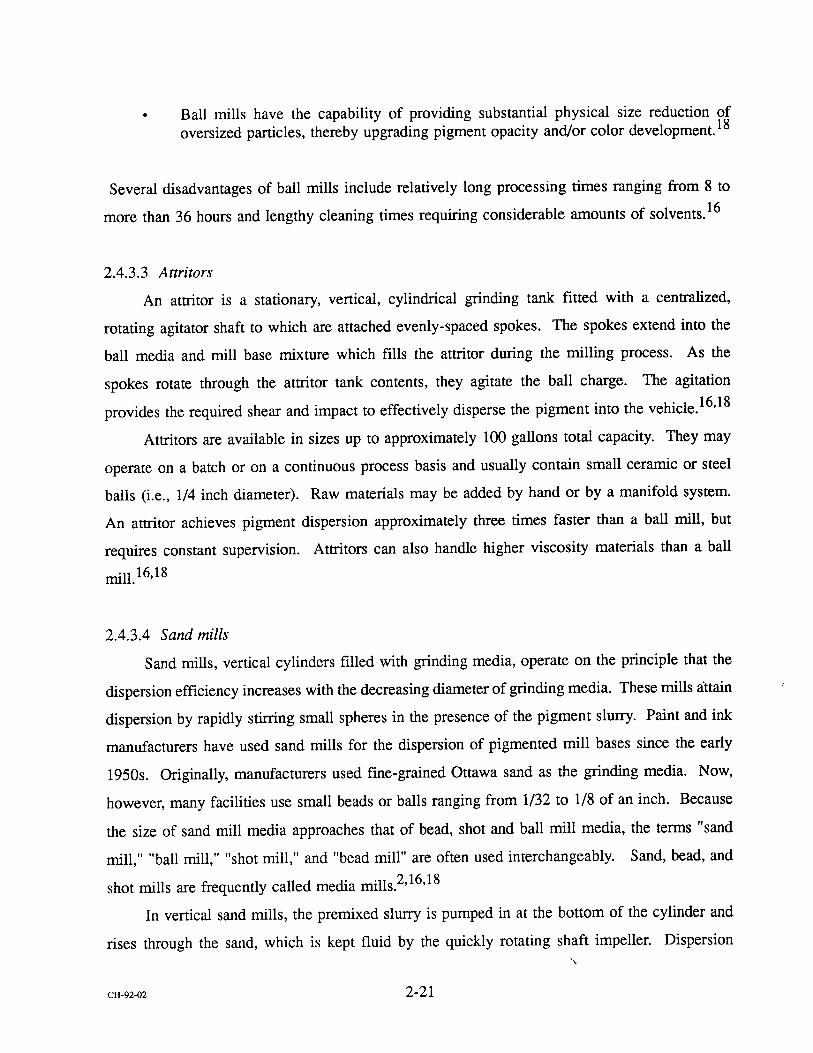
Ball mills have the capability of providing substantial physical size reduction of oversized particles, thereby upgrading pigment opacity and/or color development. 18
Several disadvantages of ball mills include relatively long processing times ranging from 8 to
more than 36 hours and lengthy cleaning times requiring considerable amounts of solvents. 16
2.4.3.3 Attritors
An attritor is a stationary, vertical, cylindrical grinding tank fitted with a centralized,
rotating agitator shaft to which are attached evenly-spaced spokes. The spokes extend into the
ball media and mill base mixture which fills the attritor during the milling process. As the
spokes rotate through the attritor tank contents, they agitate the ball charge. The agitation
provides the required shear and impact to effectively disperse the pigment into the vehicle. 16'18
Attritors are available in sizes up to approximately 100 gallons total capacity. They may
operate on a batch or on a continuous process basis and usually contain small ceramic or steel
balls (i.e., 1/4 inch diameter). Raw materials may be added by hand or by a manifold system.
An attritor achieves pigment dispersion approximately three times faster than a ball mill, but
requires constant supervision. Attritors can also handle higher viscosity materials than a ball
mill.16,18
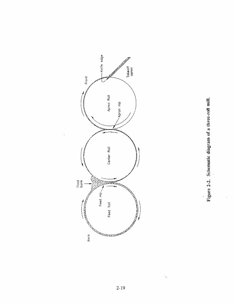
2.4.3.4 Sand mills
Sand mills, vertical cylinders filled with grinding media, operate on the principle that the
dispersion efficiency increases with the decreasing diameter of grinding media. These mills •ttain
dispersion by rapidly stirring small spheres in the presence of the pigment slurry. Paint and ink
manufacturers have used sand mills for the dispersion of pigmented mill bases since the early
1950s. Originally, manufacturers used fine-grained Ottawa sand as the grinding media. Now,
however, many facilities use small beads or balls ranging from 1/32 to 1/8 of an inch. Because
the size of sand mill media approaches that of bead, shot and ball mill media, the terms "sand
mill," "ball mill," "shot mill," and "bead mill" are often used interchangeably. Sand, bead, and
shot mills are frequently called media mills. 2'16'18
In vertical sand mills, the premixed slurry is pumped in at the bottom of the cylinder and
rises through the sand, which is kept fluid by the quickly rotating shaft impeller. Dispersion
CH-92-02 2-21

takes place as a result of pigment shearing as it rises through the chamber. Most pigments are
sufficiently dispersed when they reach the top of the chamber. The dispersed product is then
allowed to filter from the mill through a mesh which retains the sand. Older sand mills operate
with an exposed filtering screen which often becomes encrusted with dry mill base. Many newer
mills, however, have a submerged screen that eliminates plugging problems. With an ample
supply of premixed material, the sand milling process can be continuous. 2'16'18 Figure 2-3 is
a schematic of a vertical sand mill.
2.4.3.5 Bead and shot mills
Bead mills look and operate like sand mills. The only difference between the two is the
type of grinding media employed. While conventional sand mills ordinarily use Ottawa sand,
bead mills use a wide variety of synthetic media including glass, ceramic, and zirconium oxide
or zirconium silicate beads. 14'16 The term "beadmilling" developed in the 1960s when
manufacturers stm-ted using synthetic grinding media rather than sand. Many former "sand" mills
are now "bead" mills. 16
The latest bead mills are closed agitated ball mills with a stationary horizontal cylindrical
grinding container enclosing a driven shaft which agitates 1 to 3 mm diameter grinding beads.
The small size of the grinding media necessitates that particle size in the mill base feedstock be
ground and dispersed to below 250 ]am. A properly set up bead mill can disperse to below 20
]am in a single pass through the mill. 19 Bead milling systems are available in sizes ranging from
1.5 to 1,900 gallons. 16 Most bead mill manufacturers, with few exceptions, use glass, zirconium
oxide or zirconium silicate, ceramic, alumina, and in certain cases, steel ball grinding media.
They may be used either for batch or continuous processing. 2'14'18
Shot mills are also similar to sand mills. These rugged units have a narrow, upright,
cylindrical tank equipped with a rotating vertical shaft that sustains a series of evenly spaced,
stainless alloy, circular platforms. The platforms rotate through the media/mill base mixture.
High-speed shot mills work best with small steel or ceramic grinding media. The mill operates
under internal pressure and therefore is able to grind materials with high viscosities. The mill
also has a variable-speed pump and submerged filter which rotates with the shaft. 18
CH-92-02 2-22

Rotating shaft
Screen for holding back sand particles while allowing free
flowthrough of dispersed mill base
Exit port for discharge of dispersed
mill base to apron
for mill base sandwich between two impeller disks
(rolling double-doughnut grinding action)
Water jacket
Valve controlling rate of flow of mill bose
Impeller disks
50/50 volume mix of mill base and sand
Bottom entry for introducing homogeneous premix of mill base paste or
slurry to sand grinder
Figure 2-3. Schematic drawing of conventional sand mill.
2-23

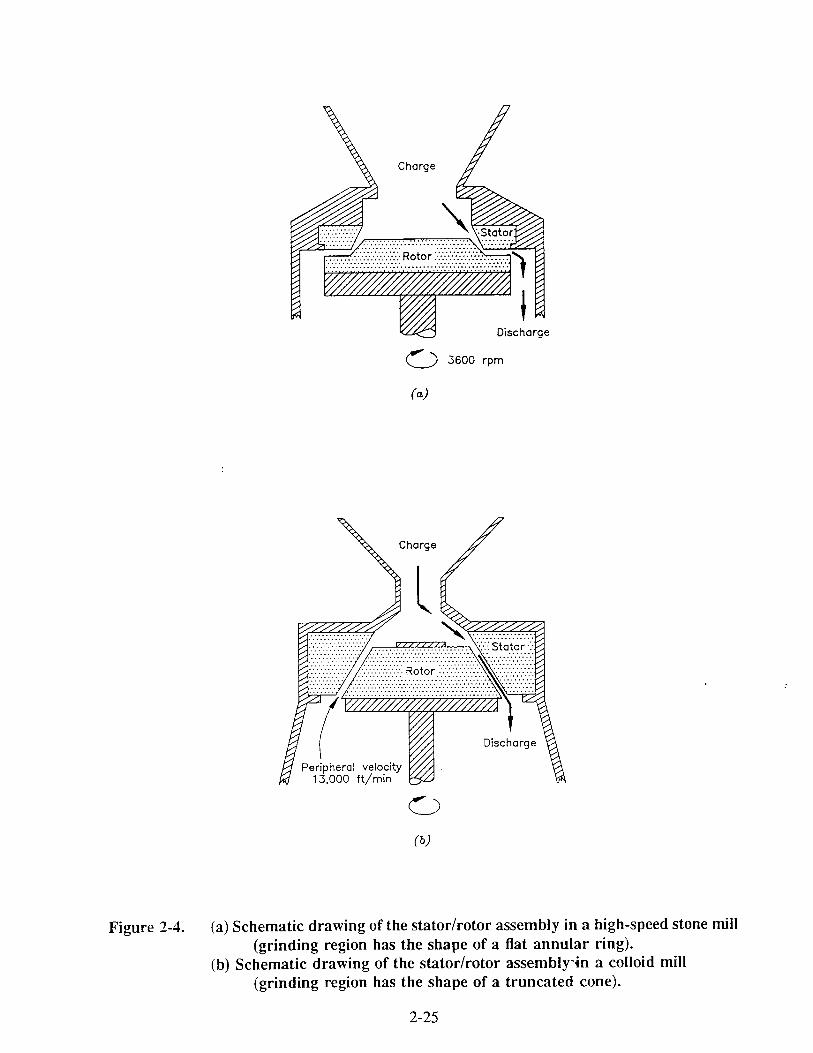
2.4.3.6 High-speed stone and colloid mills
High-speed stone and colloid mills, although not as common as many of the other pigment
grinding mechanisms, are another method of achieving pigment dispersion. Modem stone
(Carborundum) mills consist of two precisely shaped Carborundum stones working against each
other, as illustrated in Figure 2-4a. One stone, the stator, is held stationary while the other stone,
the rotor, is rotated at high speed from 3,600 to 5,400 rpm. The prernixed mill base is fed by
gravity or under pressure into the charge area above the rotor. A viscous laminar flow, yielding
pigment dispersion, results as the material moves through the grinding gap or the small space
separating the two stone surfaces. Because the material spends only a fraction of a second
between the stones, the dispersing action of the stone mill serves to refine rather than as a pure
mixing and grinding operation. Stone mills produce the best quality product when they are fed
a well-mixed, viscous premix. 18
Colloid mills differ from stone mills in their material of construction and their gap
configuration. Figure 2-4b illustrates the truncated cone arrangement distinguishing the two
mills. The rotor and stator are designed with smooth, ground, and lapped faces which ensure a
uniform cross section in the material in the grinding gap. Mill base consistency results in
maximum shear and efficient milling. The rotor and stator in colloid mills may be constructed
of Carborundum stones, high-nickel alloys, or Invar, an alloy with a low coefficient of expansion.
Like stone mills, colloid mills must be provided with a well-mixed, viscous material feed. 18'20
Both the stone mills and the colloid mills traditionally operate as open systems. However,
both may be converted to closed systems using an accessory pump to provide the material fe•d. 18
2.4.3.7 High-speed disk dispersers
High-speed disk dispersers are the most universally used method of dispersion in the paint
and ink manufacturing industry. Their popularity continues to increase as compact, efficient,
heavy-duty power sources and readily dispersible pigments become more available. Some paint
and ink blends are manufactured entirely in one piece of equipment using high-speed disk-type
impellers. Essentially, the high-speed disk disperser consists of a circular, steel, saw-blade-type
impeller attached to the end of a steel shaft. The disk is suspended in a mixing pot which may
be jacketed for water-cooling. Because there is no grinding media present in the mixing vat, the
CH-92-02 2-24
Charge
• :.:.:.:.:.:.:.::i:iiiiii?ii?iiiiiiiiiiii..•..t•.°..r. !i!i!iiiii!i!iii!iii!ii:•)
Discharge
3600 rpm
Peripheral ve.locity •////J. 15,000 f•/min •
(•)
Figure 2-4. (a) Schematic drawing of the stator/rotor assembly in a high-speed stone mill (grinding region has the shape of a flat annular ring).
(b) Schematic drawing of the stator/rotor assemblyqn a colloid mill (grinding region has the shape of a truncated cone).
2-25

pigment disperses on itself and against the surfaces of the rotor. While high-speed disk
dispersion may work well with some products such as undercoats and primers, it may not be
appropriate for high-quality paints and inks. It can, however, be used for premix operations of
high-quality paints, thus reducing the number of passes in a media mill or reducing the amount
of time spent in a ball mill. 2'16'18'21
High-speed dispersers provide a simple, quick, and relatively inexpensive means of
distributing easy-to-disperse pigments in conventional vehicles on a batch processing basis.
These dispersers are also capable of handling all phases in the preparation of some paints and
inks (i.e., preassembly and premix, pigment grinding and dispersion, and product finishing) in
one piece of equipment. In addition to its dispersion abilities, the high-speed disperser can be
used in premix and blending (postmix) operations. Another advantage is the comparatively low
initial capital investment and low maintenance costs. The primary disadvantage of the high-speed
disperser is its inability to disperse hard agglomerates. 18
A modificfftion of the high-speed disperser is a variable speed disperser. Variable speed
systems allow the incorporation of dry powders into a liquid medium at low speed with minimum
dusting. The speed is increased once initial wetting is complete. 19
A second variation of the high-speed disperser is a rotor stator type machine similar to the
set-up found in stone and colloid mills. Instead of disk type impellers, this disperser operates
with a rotor stator unit. The stator is mounted on several shafts extending from the equipment
housing, while the rotor is attached to a center disperser shaft which would typically hold a disk
type impeller. The rotor stator unit may be either high-speed or variable-speed. In addition,
newer models are quiet and more efficient than conventional high-speed dispersers. 22'23
Another variation of the high-speed disperser/portable mix tank operation is the Kady mill.
This mill consists of a high-speed disperser or agitator in combination with a fixed mix tank.
The tank is jacketed, allowing for heating capability. It is also equipped with a permanent lid
which can be opened during product filling operations and sealed during the mixing and
dispersion process. As with disperser/portable tank operations, Kady mills contain no grinding
media in the mix tank allowing the pigment to disperse on itself and against the surfaces of the
rotor. Kady mills are often used in the production of high-gloss paints and inks which require
heat to develop the gloss characteristics. 13'14
CH-92-02 2-26
2.4.3.8 High-speed impingement mills
High-speed impingement mills or kinetic dispersion mills disperse pigment agglomerates
by impact. This mill consists of a slotted rotor and stator as shown in Figure 2-5. Material is
sucked in at both the top and the bottom of the mill and is thrown outward by the rotating slots
on the rotor against the close-fitting stator. The high velocity and forceful impact of the particles
results in dispersion. 18
Impingement mills are most efficient when they are fed with a low-viscosity, easily
dispersible pigment/vehicle mixture. As impingement mills are a batch process operation, no
material premixing is required. The fluid vehicle (low solids content) is placed in the mill tank
prior to starting the milling process. Once the rotor has started, pigment is rapidly fed into the
tank. Batch grinding time averages less than 25 minutes. 18
2.4.3.9 Horizontal media mills
The horizontal media mill is basically a vertical mill turned 90 degrees. This configuration
improves the performance of the mill by creating better material flow and by increasing the
media loading capacity from 85 to 90 percent of the chamber volume. The increase in media
loading from 50 percent in vertical mills to 90 percent in horizontal mills provides increased
milling efficiency. 24 When provided with the proper premix feed, a standard horizontal media
mill offers the most efficient one-pass operation. Properly equipped horizontal mills provide
three times the productivity on an equal volume basis as the open-top sand and bead mills. 25
Horizontal media mills are closed systems. The filtering screen is enclosed by a sheet
metal cover which controls solvent losses and expands the range of products that can be
processed. Although the mill base moving through the chamber should be of low viscosity to
allow the grinding media to move with maximum velocity, manufacturers using horizontal mills
are no longer concerned about solvent evaporation and the mill base drying on the screen
(causing the mill to overflow). 24'26
Horizontal mills range in size from 1.5 liters (0.4 gallons) to 500 liters (132 gallons). Most
mills are equipped with a secondary jacket which allows for water cooling. The mills are able
to use any of the common media currently manufactured including glass beads, ceramic beads,
zirconium silicate beads, and steel shot. 24
cFI-92-o2 2-27

Exit
Figure 2-5. Schematic drawing of the milling head of a high-speed impingement (kinetic dispersion) mill.
2-28

2.4.4 Product Finishing
Final product specifications are achieved in the product finishing step which consists of
three intermediate stages: thinning, tinting and blending.
2.4.4.1 Thinning (letdown) Material letdown, or thinning, is the process by which a completed mill base dispersion is
let down or reduced with solvent and/or binder to give a coating which is designed to provide
a durable, serviceable film that is easily applied to the substrate.18 The volume of the paint or
ink may increase significantly at this point depending on the final product specifications.
2.4.4.2 Tinting
Tinting is the process of adjusting the color of completed mill base dispersions. Normally,
an operator will •ollect a sample of the paint or ink once it exits the milling equipment. This
sample willbe taken to the laboratory and compared to the desired color standard. Various
combinations of pigments, solvents, resins, and pastes are added to the material to meet the color
requirements .9,12,13
2.4.4.3 Blending
Blending operations occur once the necessary additions have been made to the completed
mill base dispersion. Blending is the process of incorporating the additions into the material in
order to meet the desired product specifications. In the case of batch operations, blending may
simply consist of additional milling in a ball mill or added mixing and dispersing in a portable
mix tank/high-speed disperser set-up. In other cases, the mill base dispersion is transferred to
fixed agitated blend tanks or additional mix tank/disperser operations. In each case, material
adjustments for thinning and tinting are added through top openings, agitated, and gravity fed or
pumped out bottom or side spigots for filling operations. 9'12'13'14
CH-92-02 2-29

2.4.5 Product Filling
The final step in paint and ink manufacturing is product filling operations. After the
material has been blended, it is transferred from the blend tanks into containers for product
shipment. The transfer step normally involves product filtration.
2.4.5.1 Filtering Filtering acts to screen out impurities (e.g., dust, gelled resin, and pigment aggregates) and
to enhance the quality and uniformity of the product. In the case of media mills, filters prevent
the grinding media from exiting the mill and entering shipment containers. 2'14
Paints and inks may be filtered in a variety of ways. Some facilities simply attach cheese
cloth or cloth socks to the exiting blend tank spigot. 9'13'14 Other plants use filtering equipment
such as strainers br sieves. The Russel Finex strainer consists of a vibrated screen and hopper
through which product flows prior to entering shipment containers. The screens may be either
metal mesh, supported nylon, or another synthetic fiber. Another strainer, the Jenag strainer, has
a vertical chamber holding fiber filters. The paint is fed by gravity or pump to the chamber and
drawn through by vacuum. 2 High quality finishes, such as those used for automobiles and
industrial products, may be pumped through wound polypropylene or other resin cartridge
filters. 2'12 Bag filters, made from felts (rayon, polypropylene, or nylon) or gauzes
(polypropylene, nylon, or polyester), can be attached to the flanged end of a supply line and
supported by a vibrating wire basket. These bags are usually washable and used only for small
batches. 2,13
2.4.5.2 Material transfer
Once the material has been filtered, it can be transferred into pails, drums, tote tanks, tote
wagons, or another container for shipment. Although most paints are sold by volume, most
manufacturing facilities find it more convenient to fill the shipping containers by weight using
the specific gravity of the paint or ink. Filling may be accomplished either manually or
mechanically depending on the number and size of the containers to be filled. 2'12
CH-92-02 2-30

2.5 REFERENCES
1987 Census of Manufactures. Industry Series. Department of Commerce. Washington, D.C.
11.
12.
13.
14.
15.
Paints and Allied Products. U.S.
Morgans, W.M., Outlines of Paint Technology, Third edition, Halsted Press, John Wiley & Sons, New York, NY. 1990.
"Paint Manufacture and Painting," IARC Monographs, 47: 329-442, 1989.
Lorton, Gregory A., "Waste Minimization in the Paint and Allied Products Industry," JAPCA, 38(4): 422-427, 1988.
Gale Research, Inc. Ward's Business Directory of U.S. Private and Public Companies- 1991, Volume 4. Detroit, MI. 1991.
1987 Census of Manufactures. Industry Series. Miscellaneous Chemical Products. U.S.
Department of Commerce. Washington, D.C.
Wolfe, Herbert Jay, Printing and Litho Inks, Sixth edition, MacNair-Dorland Company, New York, NY. 1967.
Printing Ink Handbook, compiled by Technical and Education Committees, National Association of Printing Ink Manufacturers, Inc. and the National Printing Ink Research
Institute, National Association of Printing Ink Manufacturers, New York, NY. 1967.
ICI trip report.
U.S. Environmental Protection Agency. Guides to Pollution Prevention: The Paint
Manufacturing Industry, EPA-625/'7-90-005. Risk Reduction Engineering Laboratory. Cincinnati, OH. 1990.
Berlow, James R., Howard D. Feiler, and Paul J. Storch, "Paint and Ink Industry Toxic
Pollutant Control," reprinted for the Pollution Prevention Pays Program, Pollution Prevention Pays Library, C&AP 88. Raleigh, NC.
PPG trip report.
Perry & Derrick trip report.
Borden trip report.
U.S. Environmental Protection Agency. Control Techniques for Volatile Organic. Emissions from Stationary Sources. EPA-450/2-78-022. Office of Air Quality Planning and
Standards. Research Triangle Park, NC. 1978.
ca-gz-oz 2-31
16. Lambourne, R., ed., Paint and Surface Coatings, John W'lley & Sons, New York, NY.
1987.
17. MixMor product brochure. "Mixers and Agitators for Industry," Mixmor, King of Prussia, PA. 1989.
18. Patton, Temple C., Paint Flow and Pigment Dispersion, Second edition, John Wiley &
Sons, New York, NY. 1979.
19. Denison, B., "Bead milling a practical guide," Journal of the Oil and Colour Chemists' Association, 73(6): 256-260, 1990.
20. Premier Colloid Mills product brochure. "The Ultimate in Dispersing and Emulsifying," Premier Mill, Corp., Reading, PA. 1988.
21. Tippett, Jerome E, "Selecting Dispersion Equipment," reprinted from Modern Paint and
Coatings, by Schold Machine Company, St. Petersburg, FL. May 1980.
22. Wagman, Scott and Alan E. Hodel, "Rotor stator yields uniform dispersion in 1/4 the time," reprinted by Schold Machine Company, St. Petersburg, FL, from Chemical Processing, 50(8): 44-46, 1987.
23. Whitlock, Robert and Alan E. Hodel, "Disperser Cuts Processing Time 80% Produces
Smoother Flowing Product," reprinted by Schold Machine Company, St. Petersburg, FL, from Chemical Processing, July 1989.
24. Zoga, Christ, "Horizontal Media Milling With Computer Controls," reprinted from Modern
Paint and Coatings, by Premier Mill Corporation, New York, NY. June 1984.
25. Zoga, Christ, "Dispersion and Milling Methods to Increase Plant Productivity," reprinted from Modern Paint and Coatings, by Premier Mill Corporation, New York, NY. May 1989.
26. Sneeringer, John R., "Consider the Horizontal Mill," reprinted from CPIIO0, by Premier
Mill Corporation, New York, NY May/June 1986.
cH-9z-oz 2-32
CHAPTER 3
VOLATILE ORGANIC COMPOUND EMISSIONS,
REGULATIONS, AND PERMITS
3.1 GENERAL
This chapter describes the potential sources of VOC emissions in ink and paint
manufacturing facilities. Potential emission sources are identified and characterized based on
available literature and plant visit results. This chapter also discusses current industry emissions
as defined and described by published documents, State permit information, State VOC
regulations, and individual industry sites.
In 1987, the paint and ink industries consumed an estimated 2,750 million pounds of
solvent. 1,2 Although this number is expected to decrease as paint and ink manufacturers continue
to move toward p•:oducts with lower VOC contents, it still accounts for 0.05 percent of total VOC
emissions. Other statistics indicate that the application of paints is the fourth-largest VOC
source. 3 The United Kingdom attributes solvent emissions of 94,000 tons per year to the paint
and paint application industries. 4
The primary factors affecting the emission of organic compounds are the types of solvent
used in the manufacturing process, the temperature at which these compounds are mixed, and the
methods and materials used during cleanup operations. According to EPA publication AP-42,
even under well controlled conditions, approximately 1 to 2 percent of the solvent brought into
the facility is lost during manufacturing operations. 5
3.2 SOURCE IDENTIFICATION AND CHARACTERIZATION
3.2.1 Introduction
Volatile organic compounds are released from several types of equipment and handling
operations throughout the paint and ink manufacturing process and during cleanup operations.
Emissions can be categorized according to the four manufacturing processes (i.e., preassembly
CH-92-02 3-1

and premix, pigment grinding or milling, product finishing, and product filling) and cleaning
operations.
3.2.2 Preassembly and Premix
The vast majority of paint and ink facilities begin the manufacturing process by thinning
resins with solvents, alcohols, oils, and/or water. The equipment items most often used in this
premix and preassembly operation are drums and portable tanks in combination with mixers.
Emissions from other premix equipment, such as grinding and milling devices, will be discussed
in Section 3.2.3.
Portable mix tanks, either alone or in combination with an agitator, are a common
emissions source. Portable mix tanks are used to mix product and to keep the pigment in
suspension. They are also used to u'ansfer material from one manufacturing stage to the next.
While they are b•ing used for mixing, the tanks are often, but not always, covered with lids. If
a cover is used on a mix tank during mixing, it will have a small opening through which the
agitator shaft extends. In some cases, only a splash guard is used to cover the back half of the
mix tank. If mix tanks are used for temporary storage, they are often covered with a solid lid.
None of the lids seal with the mix tanks. 6-8
In some cases, products are premixed in 55 gallon drums. Like the portable mix tanks, the
drums are often covered with non-sealing lids. If a cover is used on a drum during mixing, it
will have a small opening for the agitator shaft. 6'9
Emissions occur during material loading when the tank or drum is uncovered or when the
lid is open. VOCs may also be released through the agitator shaft opening and from around the
edges of the lid during the mixing process. The quantity of material released varies with type
of solvent, agitator mixing speed, material temperature, and type of cover. More organics will
be released with highly volatile solvents, increased agitator speed, and warmer temperatures.
3.2.3 Pigment Grinding or Milling
The equipment used in grinding operations includes roller mills, ball and pebble mills,
attritors, sand mills, bead and shot mills, stone and colloid mills.• high-speed dispersers,
cH-92-02 3-2

impingement mills, and horizontal media mills. Emissions of VOCs from dispersers were
discussed in the previous section.
Roller mills are used to manufacture high-quality paints and inks with a high solids content.
The mill base vehicles used on roller mills normally contain from zero to 40 percent volatile
content. Because the roiling cylinders on roller mills are exposed to the atmosphere, the majority
of the volatile content in the mill base vehicle is expected to evaporate during the course of the
grinding process. 9'10
Grinding with ball and pebble mills approaches a closed system operation. The only
opening in these mills is the chute through which raw materials or premixes are added and the
spigot which is used for product filling operations. VOC emissions occur during these
processes. 6,8,9
Attritors also approximate closed systems. Emissions may occur from the opening
surrounding the agitator shaft and/or at product outfall. 7
Older vertical media mills (i.e., sand mills, bead mills, and shot mills) operate with an
exposed filtering screen. As the mill base rises through the chamber and becomes exposed to
the air, the solvent constituent evaporates, often leaving the screen encrusted with dry mill
base. 10'11 Media mill operators may apply solvent to unclog the screen or they may scrape
down the filter with a coarse, dry brush. 6-8 Fewer emissions occur from newer vertical media
mills which have submerged filtering screens. 10 Additional emissions of VOCs result from
adding raw materials and from product filling operations.
Both the stone and the colloid mills traditionally operate as open systems. Emissions
normally occur as the mill base feedstock is added to the charge chute on top of the rotor/stator
arrangement. Similarly, emissions may occur after grinding as the material exits through the mill
spillway. Enclosing the spillway and using a closed charge chute with an accessory pump will
reduce overall emissions. 10,12
One variation of the high-speed disperser is the Kady mill. As with the emissions from
other dispersers, emissions from Kady mills occur during material additions and product filling.
However, unlike other dispersers, the Kady mill may be heated, resulting in additional solvent
volatilization. 9
The majority of the emissions from impingement mills also occur during the addition of
raw materials and while emptying the mill of product. Impingement mills are potentially high-
c•-92-02 3-3
emission processing equipment because they require low-viscosity (low solids) vehicles. Ideally,
the first vehicle addition would contain only ten percent by weight solids. Subsequent additions
might contain a higher solids content. 10
Horizontal media mills are efficient, closed-system milling devices. The filtering screen
is enclosed by a sheet metal cover which controls solvent losses and expands the range of
products that can be processed. Although the mill base used in a horizontal mill should be of
low viscosity, paint and ink manufacturers do not have to worry about VOC emissions during
the grinding process. The mill base for most horizontal mills is pumped from containers or
premix equipment through an enclosed piping system. Material discharge is also through
enclosed pipes or hoses. 6'13
3.2.4 Product Finishing
The emissiOns that occur during the product finishing step are mainly a result of material
additions during the tinting and thinning stages. If a product is finished in a mix tank/disperser
set-up, emissions are similar to those mentioned in Section 3.2.2. When material is finished in
a fixed blend tank, releases occur during product additions through the top hatch, which normally
does not seal with the blend tank. 7'8
3.2.5 Product Filling 6"9
Emissions occur during almost all product filling operations. The extent of these emissions
is determined by the volatility of the solvent in the paint or ink formulation, the temperature at
which the product enters the shipment container, the method of material transfer, and the method
of filling. Emissions increase with temperature and highly volatile solvents.
One source of emissions is scale systems, where solvent and resin raw materials are
measured and transferred from storage tanks to the process tanks, between process tanks, or from
process tanks to shipment containers. Emissions may occur during transfer and hose connecting
and disconnecting. Another type of scale system consists of a floor scale, a drum, a drum
dispenser, and a receiving container. Material is pumped out of the drum into the receiving
container. Emissions occur during material transfer and free-fall into the receiving container.
CH-92-02 3-4

In some cases, material is transferred by bucket and dip method. Here, emissions occur while
the product is exposed to the air and while it is being scooped and transferred to the second
container.
Another emission source is product filtering. As product flows through a filtering device,
it is often exposed to the air, resulting in releases of VOCs.
Filling operations also result in VOC emissions. In one plant, portable mix tanks are
mechanically lifted and tilted, allowing the finished product to gravity feed into containers for
shipment. Some facilities allow product to gravity feed from processing equipment through
filters into shipment containers. Emissions result from product free-fall and material splashing.
3.2.6 Equipment Cleaning
In addition to emissions from process operations, VOCs are also released from a variety
of cleaning oper£tions. Solvent based materials are used to clean equipment in which solvent
based products are manufactured, while water based supplies are used to clean after water based
production. Emissions occur during solvent addition and removal as well as during the cleaning
process.
In many facilities, manufacturing equipment is cleaned manually on the production floor
on an as-needed basis. In some cases, cleaning is performed after each batch, and in other cases
equipment is cleaned after a series of batches. The cleaning frequency depends on the number
and size of batches processed, the size of the equipment to be cleaned, and the color and type
of product manufactured. The standard method of cleaning grinding equipment involves
emptying the mill of product and then adding solvent to the vessel to capture remaining product
residue. The wash solvent is normally drained from the tank and either disposed of as hazardous
waste or recycled. 6-9 Mix tanks and agitator blades may be cleaned with solvents, brushes,
and/or rags. 6 Roller mills are often cleaned by hand using rags and solvent. 9
Larger facilities may have areas designed specifically for cleaning operations. In these
facilities, equipment cleaning may be more automated (i.e., automatic tank washers and spray
guns), but emissions still occur during the process. 7
CHo92-02 3-5

Equipment cleaning operations account for over 80 percent of the paint industry's waste.
Although solvents are not the only waste generated during cleaning processes, they are a major
contributor. 14
3.3 EMISSION FACTOR DATA
3.3.1 Introduction
There is little emission factor information available for the manufacture of paints and inks.
Figures range from process solvent losses of one to two percent under well controlled conditions
to losses of 100 percent for specific volatile organic compounds. 5'15 The 100 percent loss figure
is obviously a "worst case" estimate, as enough volatile components remain in the paint or ink
to allow it to remain fluid and workable. Some studies indicate that a coating film which is dry
to the touch may :retain five to ten weight percent solvent for several years because of the slow
diffusion rates encountered at the air-f'dm interface. 16 Many paint and ink manufacturing
facilities calculate total plant VOC emissions based on raw material consumption rather than
calculating emissions from processes or equipment by an alternative method. Total emissions
therefore reflect solvent losses during manufacturing, cleaning operations, and storage. 17
Emission factors for specific equipment could be developed using theoretical equations,
mass balance, or emission testing. The development of a theoretical equation could be based on
solvent volatility, vapor pressure, equipment size, and degree of agitation. Other variables to be
considered include equipment heating/cooling capabilities, ambient conditions, and exposed
surface area and tank cover efficiency (in the case of mixing vats and/or drums). Both the mass
balance and the emission testing methods would require industry trials. 17
Much of the currently available emission factor data is based on U.S. EPA's Compilation
of Air Pollutant Emission Factors (AP-42). Data for paint and ink manufacturing are found in
Table 3-1. The table indicates that the majority of the VOC emissions result from varnish
production (for paints) and vehicle cooking (for inks). Because these processes are typically
performed in chemical facilities rather than in paint and ink manufacturing facilities, their
emissions are not addressed in this report. 5
CH-92-02 3-6

TABLE 3-1. UNCONTROLLED EMISSION FACTORS FOR PAINT, VARNISH, AND PRINTING INK MANUFACTURING a'b
Type of Product/Process
Emission Factor Rating
Nonmethane VOC
kg/Mg of product Ib/ton of product
Paint c
Varnish c
Bodying Oil
Oleoresinous
Alkyd Acrylic
Ink Vehicle Cooking d
General
Oils
Oleoresinous
Alkyds
C
C
E
15 30
20 40
75 150
80 160
10 20
60 120
20 40
75 150
80 160
Source: Reference 3 aInk manufacturing data is based on paint & varnish information bAfterbumers
can reduce VOC emissions by 99% CExpressed as undefined organic compounds whose composition depends upon the type of
solvents used in the manufacture of paint & varnish dlnk nonmethane VOC emissions are a mix of volatilized vehicle components, cooking decomposition products and ink solvent
Ten or more tests at different plants with a single, standard method. These tests are not necessarily EPA reference method tests, although such reference methods are certainly to be used as a guide.
Several test results using an accepted method that reflect a large portion of the population.
A small number of tests or tests employing several different or nonstandard methods.
A few or a single source test that may be of questionable quality; or a factor derived for a different
source type that has been "transferred."
Engineering judgment
CH-92-02 3-7

Also included in the Table 3-1 is an emission factor data quality rating which may range
from A to E, with A being most reliable. AP-42 indicates that high quality ratings are given to
emission factors based on multiple observations at many different plants, while low ratings are
given to emission factors based on single observations of questionable quality or extrapolated
from other emission factors for similar processes. The ratings given in AP-42 are considered a
general indicator of the accuracy and precision of a given factor used to estimate emissions from
a large number of sources. The rating system for a particular emission factor test data set is
based on the data standards developed by the U.S. EPA's Office of Air Quality Planning and
Standards for inclusion in AP-42. The rating system is included in Table 3-1.
3.3.2 Current Regulations 7'18"25
Regulatory requirements for VOCs vary from State to State and within some jurisdictions
of certain States. :At the very least, VOC regulations should be in place in non-attainment areas
where source size may be a basis for control. VOC emission limits are often determined by end
use categories commonly called EPA Control Technique Guideline (CTG) Sources and by EPA
established Reasonably Available Control Technology (RACT) Limits. Because paint and ink
manufacturing facilities are not identified by any current CTGs, individual States may develop
RACT limits. In many States only those non-CTG facilities emitting more than 100 tons per year
are controlled, while in other States the limit may be 15 pounds per day. Plants releasing less
than the specified limit are exempt. The Clean Air Act Amendments of 1990 will require non-
CTG sources in ozone non-attainment areas to control VOC sources that emit 10, 25, 50, or 100
tons per year VOC depending on the severity of the problem.
Several States currently have rules regulating VOC emissions from paint and ink
manufacturing facilities. Most of these regulations have the following common requirements and
exemptions:
Covers must be used on all stationary and portable mix tanks, dispersion mills, and
tanks containing VOC used for cleanup.
Grinding mills installed after the date of regulatory enactment must be equipped with fully enclosed screens.
CH-92-02 3-8

Equipment must be monitored and inspected for leaks on a regular basis.
Facilities emitting less than 100 tons per year VOC are exempt from regulation.
Facilities manufacturing primarily water based paints and inks are exempt.
The State of Ohio is one State that has developed an RACT case-by-case regulation. In
1988, Ohio enacted Ohio Air Pollution Control (OAC) rules 3745-21-01 and -09, which subjected
the Cleveland PPG Industries, Inc. (PPG), paint manufacturing facility to site-specific
requirements for VOC emissions based on RACT. Because the emissions from the
manufacturing facility and the paint laboratory met or exceeded 100 tons of VOC annually prior
to rule enactment, the facility (manufacturing and laboratory) was classified as a "major" source.
As such, Ohio wrote non-CTG rules for the paint manufacturing operations and paint laboratory
operations specifically for PPG. Ohio's paint manufacturing RACT rules and the paint
manufacturing rules from other States are summarized in Table 3-2. Table 3-3 summarizes
similar rules for the ink manufacturing industry.
3.3.3 Permits 26"30
Selected permits for equipment at paint and ink manufacturing facilities were retrieved from
the State of Ohio. Many pieces of manufacturing equipment (e.g., mixers, grinding mills,
dispersers, and filling equipment) are classified as stationary sources which are subject to the Best
Available Technology (BAT) requirement of OAC Rule 3745-31-07 (G)(2), "The control of
emissions of organic materials from stationary sources." This rule limits VOC emissions from
stationary sources to 8 pounds per hour and 40 pounds per day. In addition to these emission
limits, some equipment is subject to other special terms and conditions including the following: 26
BottomfiII requirements: All solvent additions to the designated equipment (mainly tanks) shall be accomplished by bottom fill, with the exception of a small amount of
solvent per batch (i.e., 50 gallons) for making adjustments for product specifications.
Operational limits: Some sources are limited to processing time each day where
processing includes all periods in which the tank is being filled, materials are being added, mixing is occurring and/or cleaning of the tank. Holding time is not
CH-92-02 3-9

0
3-10
"m
0
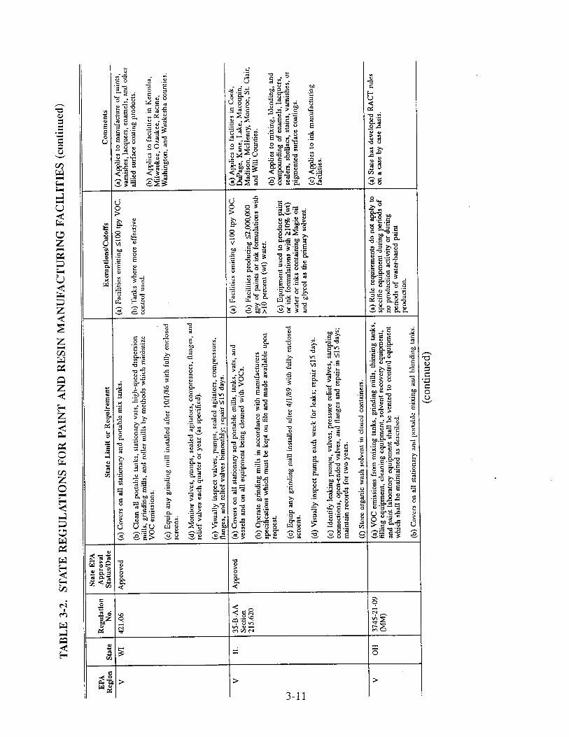
• v-i •
3-11

3-12
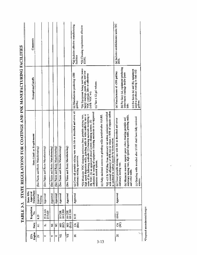

considered to be processing time. Solvent use per day or quarter may also be limited.
Recordkeeping and reporting: Some facilities are required to maintain daily records of individual source processing time with product identified and batch start and stop times indicated. Other recordkeeping requirements include tracking daily solvent use
with amount and type indicated. In addition, a facility may be required to conduct routine inspections of equipment and record the results of the inspections and any
necessary repairs.
New product notification: Prior to manufacturing any new products, for other than
process development and/or testing, some facilities must submit written notification
to the Ohio EPA.
Equipment modifications: In most facilities equipment is required to be covered or
enclosed during manufacturing operations.
Additional requirements will apply if a given facility operates add-on air pollution control
equipment. The :Cleveland PPG manufacturing facility, which is mentioned in Section 3.3.2,
controls VOC emissions by venting fumes from individual sources to a REECO (Regenerative
Environmental Equipment Company) thermal incinerator. PPG's permits (and the RACT rule)
name the following requirements:
"... the VOC emissions from the equipment included within the paint manufacturing operations shall be vented either directly or by means of a building or local area
exhaust to a control system which shall maintain compliance with any of the
following requirements: 7'26
(a) A minimum control efficiency of 98.0 percent by weight for the VOC emissions;
(b) A maximum outlet VOC concentration of twenty parts per million by volume (dry basis); or
(c) A minimum incineration temperature of one thousand five hundred degrees Fahrenheit."
Similar permit requirements apply to other facilities operating air pollution control devices.
Appendix B contains tables which have a selection of permit requirements from several States.
The States included are Ohio (Table B-l), California (Table B-2), Illinois (Table B-3), Texas
cri-9z-0z 3-14

(Table B-4), and other States (Table B-5). The information included in these tables gives a
general idea of the quantity of VOC emissions occurring at different size facilities. In some
cases, the emission data is divided by source category (Tables B-1, B-4, and B-5). The emission
data listed in the tables is most likely based on theoretical equations rather than on actual test
data.
Information retrieved from the State of Ohio lists vessel capacity, vessel size, abatement
methods, VOC emission limits, control efficiencies, and applicable operational limits. Two
methods of abatement used to control VOC emissions are carbon absorption and carbon
adsorption. Both the adsorbers and the absorbers operate at 95 percent efficiency.
California information lists facility size and organic emission limits in both tons per year
and pounds per day. The data indicate facilities with applicable abatement devices, but does not
describe the type of device.
Information included in the Illinois table indicates estimated organic emissions in tons per
year. The abatrment devices in this table include control techniques for both VOCs and
particulate matter.
Texas data includes facility size, emission sources, speciation data, organic emissions in
tons per year, and abatement devices. Like Illinois, Texas includes information on both VOC
and particulate controls. Some of the methods used to control VOC emissions are vapor
condensors and scrubbers.
The information included in the final table, Table B-5, lists emission sources, emissions,
and abatement devices for several States.
3.3.4 Plant Trips
The trip reports for the four facilities visited during the course of this project are located
in Appendix C. All of the manufacturing facilities visited calculate total plant VOC emissions
based on raw material consumption rather than calculating emissions from processes or
equipment by an alternative method. Total emissions therefore reflect solvent losses during
manufacturing, cleaning operations, and storage. 6"9
Each of the four facilities visited is required to submit annual emission reports under the
Superfund Amendments and Reauthorization Act of 1986 (SARA) Section 313. In 1990, the
cn-gz-oz 3-15

facilities reported releases as indicated in Table 3-4. 6,8,9
used in this table indicates primarily evaporative losses.
they occur within a structure or enclosure.
Please note that the term fugitives as
These emissions may be controlled if
TABLE 3-4. EMISSIONS FOR 1990
Facility Chemical
1990 Releases (Ibs)
Fugitive Point Sources
The Perry & Derrick Company
ICI Specialty Inks (Regent Drive Facility)
Borden Packaging and Industrial Products
n-Butanol 1600 1-10
Ethyl Benzene 11-499
Ethylene Glycol 11-499
Glycol Ethers 500-999 11-499
Methyl Ethyl Ketone 13,000 1-10
Methyl Isobutyl Ketone 2,000 1-10
Toluene 19,000 11-499
Xylene 1,100 11-499
Toluene 11-499 11-499
Glycol Ethers 1,100 500-999
Methyl Ethyl Ketone 500-999 7,800
1,1,1-Trichloroethane 7,830
Toluene 11-499 500-999
Section 313 submissions for the PPG Industries, Inc., site are found in the facility trip
report located in Appendix C.
CH-92-02 3-1 6

3.4 REFERENCES
1. 1987 Census of Manufactures. Industry Series. Paints and Allied Products. U.S.
Department of Commerce. Washington, D.C.
2. 1987 Census of Manufactures. Industry Series. Miscellaneous Chemical Products. U.S. Department of Commerce. Washington, D.C.
3. Reitter, Chuck, "VOCs, ozone still major problems, and paint is right in the middle (Part 1)," American Paint & Coatings Journal, July 7:15-18, 42-43, 1986.
4. Hart, Judith, "Painting the Town Green," Chemistry & Industry, 20:638, 1990.
5. U.S. Environmental Protection Agency. Compilation of Air Pollutant Emission Factors. AP- 42, Fourth Edition and Supplements. Office of Air Quality Planning and Standards, Research Triangle Park, NC. September 1985.
6. ICI trip report and facility information
7. PPG trip r•port and facility information
8. Perry & Derrick trip report and facility information
9. Borden trip report and facility information
10. Patton, Temple C., Paint Flow and Pigment Dispersion, Second edition, John Wiley & Sons, New York, NY. 1979.
11. Lambourne, R., ed., Paint and Surface Coatings, John Wiley & Sons, New York, NY.
1987.
12. Premier Colloid Mills product brochure. "The Ultimate in Dispersing and Emulsifying," Premier Mill, Corp., Reading, PA. 1988.
13. Zoga, Christ, "Horizontal Media Milling With Computer Controls," reprinted from Modern Paint and Coatings, by Premier Mill Corporation, New York, NY. June 1984.
14. Lorton, Gregory A., "Waste Minimization in the Paint and Allied Products Indusn'-y," JAPCA, 38(4):422-427, 1988.
15. U.S. Environmental Protection Agency. Toxic Air Pollutant Emission Factors A
Compilation for Selected Air Toxic Compounds and Sources, EPA-450/2-88-006a. Office of Air Quality Planning and Standards. Research Triangle Park, NC. 1988.
16. Storfer, Stanley J. and Steven A. Yuhas, Jr., "Mechanism of Blister Formation in Organic Coatings; Effect of Coating Solvents," Paint & Resin, 57(5):8-t,2,33, 1987.
c•-92-02 3-17

17.
18.
19.
20.
21.
22.
23.
24.
25.
26.
27.
28.
29.
30.
Memo from McMinn, B., Alliance Technologies Corporation, to Blaszczak, B., U.S. Environmental Protection Agency, Office of Air Quality Planning and Standards, Control Technology Center. January 7, 1991. Request for emission factor development.
Exxon Chemical, "Guide to State Volatile Organic Compound Control Regulations," produced by Modern Paint and Coatings, April, 1991.
U.S. Environmental Protection Agency. Summary of State VOC Regulations Volume 2. Group III CTG and Greater Than 100 Ton Per Year Non-CTG VOC Regulations, EPA- 450/2-88-004. Office of Air Quality Planning and Standards. Research Triangle Park, NC. May 1988.
Regulation 1141.1. Coatings and Ink Manufacturing, Rules and Regulations, South Coast Air Quality Management District (California).
Regulation B, Rule 35. Coatings and Ink Manufacturing, Rules and Regulations, Bay Area Air Quality Management District (California).
Title 35: Environmental Protection, Subtitle B: Air Pollution, Chapter I: Pollution Control Board, Subpart AA: Paint and Ink Manufacturing, Section 215.620, 215.621, 215.623, 215.624, 215.625, 215.628, 215.630, 215.636. Rules and Regulations, Illinois Environmental Protection Agency.
Chapter NR 421.06. Coatings Manufacturing, Rules and Regulations, Wisconsin Department of Natural Resources.
Part 6, Rule 336.1630. manufacturing processes. Commission.
Emission of volatile organic compounds from existing paint Rules and Regulations, Michigan Air Pollution Control
Rules 3745-21-01 (Q) and -09(MM). PPG Industries, Inc., RACT rules. Ohio Environmental Protection Agency.
Permit information retrieved from the State of Ohio Environmental Protection Agency.
Permit information received from the State of Illinois Environmental Protection Agency.
Permit information received from the State of Texas Air Control Board.
Permit information retrieved from the Bay Area Air Quality Management District (California).
U.S. Environmental Protection Agency. AIRS Facility Subsystem Source Classification Codes and Emission Factor Listing for Criteria Air Pollutants Database, EPA-450/2-88- 004. Office of Air Quality Planning and Standards. Research Triangle Park, NC. May 1988.
CH-92-02 3-18

CHAPTER 4
EMISSION CONTROL TECHNIQUES
4.1 INTRODUCTION
In paint and ink facilities, VOC vapors are generated throughout the manufacturing process.
If these emissions are left uncontrolled, high concentrations of VOC can build up in the work
area, compromising workers' health, safety, and productivity. Release of VOC to the atmosphere
can result in increased levels of tropospheric ozone (03), a pollutant that causes negative health
effects in the human pulmonary system.
The amount of VOC present in the indoor and outdoor atmospheres can be reduced in the
followingways: minimizing the manufacture and use of products containing VOC, reducing the
amount of VOC emitted during the manufacturing process, and removing VOC from the air once
it has been emitted. Paints and inks may be reformulated to eliminate or minimize the amount
of VOC contained in the product. Reductions in process VOC emissions may be achieved by equipment and process modifications, improved operating practices, and recycling. Reduction
of VOC emissions to the indoor and outdoor atmospheres can be achieved by ventilating the
manufacturing area through use of well-designed capture devices and subsequently removing VOC from the ventilation air by appropriate control devices.
The concentrations of organics found in the emission streams from the process equipment
are often very low. The organics in these streams consist of alcohols, ketones, cellos.olves,
acetone, toluene, xylene, and others. 1'2 The low organic concentrations, the variety of organic constituents, and the paint and ink batch process operations often make add-on control devices
for individual sources unattractive. The following sections describe more effective emission
reduction and removal methods.
4.2 VOC EMISSION REDUCTION METHODS
Paint and ink manufacturing facilities can take several steps to minimize VOC emissions
without employing add-on controls. The methods discussed in this section will reduce waste in
addition to reducing emissions. These VOC-minimizing methods include process and equipment
CI-I-92-02 4-1

modifications, improved operating practices, and recycling. Source reduction through product
reformulation is covered in Section 4.3. It is difficult, however, to determine the overall
efficiency or impact of these VOC-minimizing methods on individual emission sources because
many paint and ink manufacturing facilities estimate total plant emissions rather than estimating
or testing emissions by process or source (i.e., filling operations, grinding operations, cleaning
processes).
4.2.1 Equipment or Process Modifications
Two stages which are amenable to equipment and process modifications are paint and ink
manufacturing and equipment cleaning.
4.2.1.1 Tank Lids
Tank lids are the most common equipment modification used during the manufacturing
process to control VOC emissions. Mix and blend tanks are a primary source of manufacturing
VOC emissions because the solvent-containing materials spend a significant amount of time in
this equipment. Ali of the States that regulate paint and ink manufacturers require that all open-
top equipment be covered during the manufacturing process (See Tables 3-2 and 3-3). Illinois,
like most of the States, requires the following of equipment lids: 3
The mill, tank, vat, or vessel is equipped with a cover which completely covers the mill, tank, vat, or vessel opening, except for an opening no larger than necess,ary to
allow for safe clearance for a mixer shaft. Such a cover shall extend at least 1/2 inch beyond the outer rim of the opening or be attached to the rim.
The cover remains closed, except when production, sampling, maintenance, or
inspection procedures require access.
The cover is maintained in good condition, such that when in place, it maintains
contact with the rim of the opening for at least 90 percent of the circumference of the rim.
Many of the lids currently used in industry are flat and some are conical. Flat lids control
emissions relatively well, but they do have some inherent flaws. The lids do not form a seal with
the mix tank and the hinged door product add chute does not always remain closed. A typical
ca-gz-0z 4-2

flat lid is illustrated in Figure 4-1. Conical lids, a better engineering design, are considered a
more efficient means of controlling emissions. However, they too have associated difficulties
caused by added weight and bulky shape. The conical lids are more difficult to handle and
damage more easily than the fiat lids. 4
Lids may be constructed of either plastic, wood, aluminum, or stainless steel. 4"7 Plastic
and wooden lids are normally one piece except for the center agitator shaft opening, while
aluminum and stainless steel lids normally have hinged openings for product additions and
sampling. Some facilities currently using aluminum lids question their safety. 4 A study
conducted in Germany indicates that having steel (e.g., carbon steel mix tank) scraping against
aluminum containing silicon (e.g., mix tank cover) could be a potential source of sparks. A fire
may break out if the sparks contact possible flammable vapors from solvent-containing paints and
inks. 8
The control efficiency of covers on mix tanks ranges from 40 to 96 percent depending on
the method used •o determine emissions. 4'9'10 These values represent the ratio of the emission
reduction to the uncontrolled emissions. They do not account for any subsequent venting to
control devices. The 96 percent value arose from studies conducted with mix tanks in the
polymeric coating industry. In this case, the demonstrator considered only evaporative losses
during the mixing process. This method of emission determination fails to include the working
losses that occur during filling and emptying a vessel containing a solvent-saturated air space. 9
A study of the efficiency of covers used in the magnetic tape manufacturing industry
indicated an efficiency of 40 percent. This study, which is considered representative of the paint
and ink manufacturing industries, accounted for both evaporative and working losses. The
analysis indicated that the covered tank would release almost no evaporative losses. The study
also stated that working losses would be 75 percent of those calculated for an open tank (i.e.,
when the covered tank is filled, only 75 percent of the solvent-saturated air is pushed out into
the surrounding air). As described by the magnetic tape study, the total emission reduction is
determined to be the difference between the emissions of the open and covered tanks. 10
A description of a third study on mix tank covers is found in the ICI trip report in
Appendix C. This study, which accounts only for evaporative losses, indicates a cover efficiency
of 88.6 percent. 4
CH-92-02 4-3

Hinged Door Allowing Agitator / • • • Shaft Entry / • x• •
• /x • Op.ening for
for Material Additions
Figure 4-1. Typical flat mix tank cover.
4-4
Studies conducted by the polymeric coating industry indicate that no significant increase
in cover efficiency is achieved by using vapor-tight covers with conservation vents rather than
tight-fitting covers. The primary benefit of conservation vents is the control of breathing losses
which result from diurnal temperature changes. Mix tanks in paint and ink manufacturing, like
mix tanks in the polymeric coating industry, are not normally exposed to these temperature
changes. 1°
4.2.1.2 Modified Milling Equipment
In some cases paint and ink manufacturers could reduce total VOC emissions by converting
some of their older milling equipment to newer, more efficient closed-systems such as horizontal
media mills. Although a wide range of products can be processed in the horizontal mills, some
cannot. The mill base must be of a low viscosity to allow the grinding media to move with
maximum velocity. The low viscosity requirement prevents some materials currently made in
other types of milling equipment from being manufactured in horizontal mills. The viscosity of
a product, along with other characteristics such as color, gloss, type of raw materials, and
processing time, often determines the appropriate type of milling equipment. 11'Iz
4.2.1.3 Equipment Cleaning
Equipment cleaning generates a high percentage of the waste associated with paint and ink
manufacturing. Because much of this cleaning is performed with solvents, equipment cleaning
is also a major source of VOC emissions. Any methods that reduce the need or frequency of
tank cleaning will also reduce emissions. Several process and equipment modifications follow.
Rubber wipers: Facilities can use rubber wipers to scrape the sides of the tank to reduce the amount of clinging paint or ink, therefore reducing the amount of solvent needed to clean the tank. Wipers can be either manual or automatic, m4
High-pressure spray heads: High pressure spray heads can be used to clean process tanks. These heads can reduce cleaning material use by 80 to 90 percent, m"
Teflon lined tanks: Teflon lined tanks will reduce the amount of paint and ink clinging to the side of the tank and will make cleaning easier, m4
Plastic pigs: Plastic or foam "pigs" may be used to clean paint and ink from process pipes. The "pig" moves through the pipes and pushes ahead paint from a previous
CH-92-02 4-5

batch which has been left clinging to the pipe walls. This process reduces solvent needed to clean the pipes and increases product yield, m'•
Automatic tub washers: Some facilities have successfully used automatic tub washers to clean process tanks. These washers form a seal with the tank, pull a vacuum, and circulate cleaning solvent on a timed schedule. 4
Another method to reduce emissions from solvent cleaning operations is to use larger media in milling equipment. Larger media rinses more easily than small media, and therefore requires less cleaning solvent. • Glass and ceramic media and sand are also easier to clean than steel
shot. •6
4.2.2 Improved Operating Practices
In addition to process and equipment modifications, VOC emissions may be reduced by following good operating procedures. Several paint manufacturing facilities in Ohio are required by permit to abide by the following good housekeeping procedures: t7
All open-ended paint manufacturing vessels shall be securely covered during periods of operation, except when adding raw materials.
During the wansfer of material to different containers, steps shall be taken to reduce and prevent splashes and spills. Any liquid or dry material spilled shall be cleaned as expeditiously as possible, but not later than the end of the daily work shift.
Waste solvent shall be collected and stored in closed containers. The closed containers may contain a device that would allow pressure relief, but would not allow liquid solvent to drain from the container prior to disposal.
The permitted facility shall provide a permanent sign or signs for the paint manufacturing equipment which states the required work and operating practices. The sign or signs shall be placed in a prominent location and be kept visible and legible at all times.
Another good operating procedure which can reduce emissions is dedicating process lines
and equipment. Equipment dedication eliminates cleaning between each product batch.
Scheduling compatible batches or batches from light to dark colors also reduces the need for
equipment cleaning. Production scheduling and dedicating equipment may be impossible,
ca-9•-o2 4-6
however, in small paint and ink facilities that operate on a batch schedule in order to meet
customer demands. In some cases, facilities operate on a same-day shipment schedule. 47
4.2.3 Recycling Techniques
One common recycling technique among paint and ink manufacturers is using spent
cleaning solvent in subsequent compatible batches. After a mill or tank has been emptied of
product, solvent is added to the vessel to capture remaining product residue. The wash solvent
is drained from the tank, staged, and recycled into the next compatible product batch. Mills may
be cleaned by replacing the residual heel of the exiting product with an equivalent amount of
solvent which is compatible with both the preceding and the ensuing batches. <6'7
Another recycling technique which reduces total solvent consumption and VOC emissions
is using countercurrent rinsing sequences. This method uses recycled "dirty" solvent to initially
clean the tank. Following this step, "clean" recycled or virgin solvent is used to rinse away the
"dirty" solvent. The countercurrent sequence, as illustrated in Figure 4-2, extends the life of
cleaning solvents. 4'6'14
4.3 PRODUCT REFORMULATION
Eliminating or minimizing the manufacture and use of products containing VOCs is the
most effective way to reduce VOC emissions. In many cases, alternatives to high-s01vent
containing paints and inks do exist. However, because many end users (i.e., finishing facilities)
are reluctant to invest the time and effort required to change to these new and developmental
technologies, manufacturers continue to make the higher solvent products. As more technically
feasible low-VOC coatings become available, regulations covering their use will be developed.
For instance, a Control Technique Guideline (CTG) is currently being developed for architectural
and industrial maintenance coatings. The production trends for these lower solvent product
formulations are illustrated in Figure 4-3. The following sections briefly discuss several coatings
which have been successfully manufactured and applied by end-users.
CH-92-02 4-7

E2 "_e ..9
4-8
0
©
0 ..C}
0

o o o
4-9

4.3.1 Powder Coatings
Powder coatings are mixtures of dry synthetic resins, pigments, solid additives, and from
zero to ten percent entrapped volatiles. Because these coatings contain no liquid solvents, they
do not emit VOC. Powder coatings are of two general resin types: thermoplastic and
thermosetting. Thermoplastic powders are comprised mainly of vinyl, nylon or fluoroplastics. Thermosetting coatings are normally epoxy, polyester or acrylic powders. 18'•9
Powder coatings currently account for 15 percent, or an estimated 118 million pounds, of
the coatings market, and future growth is expected particularly with thermoset powder coatings. 2°
Epoxy systems, because of their versatility in both decorative and functional areas, have
anticipated expansion of 14 percent per year to 105 million pounds by 1995. 2•
Powders can now be used in many paint end-user industries because of the technological
advances in the powder coating industry and because powder coating suppliers have developed custom-formulated powders. They are a feasible alternative to many OEM paints, although they
are less viable in architectural and special-purpose markets.
4.3.2 Waterborne Paints and Inks
Waterborne paints and inks contain water as the main solvent or dispersant, although most
contain 5 to 20 percent organic solvent to aid in wetting, viscosity control, and pigment dispersion. 22
Waterborne paints are of several types: latex or emulsion paints, partially solubilized
dispersions and water soluble coatings. Emulsions are the most commonly used coatings because
they can form relatively thick films without blistering. Emulsions are particularly common in
the consumer architectural market. 18
Waterborne inks are also penetrating solvent markets. The traditional solvent categories (flexographic and gravure inks) are seeing increasing production of waterborne formulations, a3
CH-92-02 4-10
4.3.3 Radiation-Curable Paints and Inks •4
Radiation-curable coatings are coatings formulated to cure at room temperature with the
assistance of a radiation source, either an ultraviolet (UV) light or an accelerated electron beam
(EB). The electromagnetic radiation energy effects a chemical and physical change in the coating
materials by forming cross-linked polymer networks. Radiation-curable coatings typically have
higher solids contents than their conventional solventborne counterparts. The majority of current
radiation-curable systems contain none of the organic solvents found in conventional paints and
inks. The film-forming components in a radiation-curable system may approach 100 percent
reactivity, which means that most (i.e., 98 to 99 percent) of the material is converted into the
polymer network and very little evaporates before the coating or ink is considered dry. Radiation-curable paints and inks have been used successfully in several areas. The graphic
arts industry, a large user of UV-curable inks and varnishes, accounts for almost 50 percent of
the radiation-curable market. For 1985, it is estimated that the graphic arts industry used 13
million pounds of UV-curable materials.
4.3.4 High-Solids Paints and Inks
The normal solids content for conventional coatings ranges from 8 to 30 percent, while
high-solids coatings typically contain greater than 60 percent solids by volume. •:'7 The
contributing solids' components in high-solids coatings are pigments and binders (resins,). 26'28
Because high-solids coatings contain less solvent and more solids, they help to lower VOC
emissions. Some high-solids materials are used in almost all of the paint and ink markets.
High-solids coatings are modifications of their solvent-based counterparts and are classified
into two general groups: two-component/ambient cured and single-component/heat converted. 18"28
Both groups are chemically composed of synthetic resins, pigments, additives and a reduced
quantity of solvent. Epoxy, acrylic, polyester and alkyd resins have been developed for single-
component systems; acrylic, polyester, epoxy and urethane resins are used in two-component
coatings. The two-component systems offer the advantage of ambient curing, thereby eliminating
the need for an oven. When mixed shortly before application, the components crosslink to form
a solid film. 18 -,_
CH-92-02 4-1 1

4.4 VOC EMISSIONS REDUCTION BY CONTROL SYSTEMS
VOC emissions can be removed from the atmosphere by an add-on control system
consisting of a capture device and a removal device. The capture device (such as a hood or
enclosure) captures the VOC-laden air from the emission area and ducts the emission stream to
removal equipment such as a recovery device (e.g., an adsorber) or a combustion device (e.g.,
an incinerator) which removes the VOC from the air. The overall efficiency of a control system
is calculated by multiplying the capture system efficiency by the removal device efficiency.
Thus, the combination of a capture device which captures 80 percent of the VOC emissions at
the emission source ducted to a removal device which removes 90 percent of the VOC in the
emission stream would yield an 72 percent overall efficiency.
Many removal devices (such as adsorbers or incinerators) have removal efficiencies well
above 90 perceht. Capture devices, in comparison, have a much larger range of capture
efficiencies.
Designing a capture system for a facility can be a more complex task than designing a
removal system. A capture system must be designed around equipment functions and layout that
can vary significantly from plant to plant. In contrast, removal systems are typically "packaged"
systems designed by the removal device manufacturer and placed away from the process
equipment, thereby reducing facility-specific demands.
4.4.1 Capture Devices
Several capture devices such as enclosures, hoods, and other devices may be used in the
paint and ink manufacturing industry to remove vapor and liquid VOC from the manufacturing
area and to transport them to an appropriate removal device. 29
Several factors are important in the design of a good capture system. A primary capture
system criterion is that the system should maximize VOC capture at the minimum cost.
Optimum cost effectiveness is generally achieved by increasing the degree of closure around the
emission area, because airflow volume is the primary factor influencing capture system cost. 29

Other necessary considerations in addition to airflow and cost include f'tre and explosion
hazards, and visibility requirements. 29 To prevent the risk of fire or explosion, the maximum
VOC concentration within capture and removal systems should be kept below 25 percent of the
VOC's lower explosive limit (LEL). Visibility must be maintained so that operators can clearly observe the manufacturing equipment when necessary. 29
A "total enclosure" device is defined as a structure that is constructed around a source of
emissions so that all VOC emissions are collected and exhausted through a stack or duct to a
control device. With a total enclosure, there will be no fugitive emissions, only stack
emissions. 1° A paint or ink manufacturing facility may be well-suited to using the "total
enclosure" approach to VOC capture. The mixing tank lid could be constructed with a surficial
flange which could be connected to a second flange at the end of flexible duct-work. The
ductwork, which is connected to a combustion or recovery device, is installed at the mixing station and is attached to the mix tank lid during mixing operations. Although it is infeasible to
duct emissions from a portable tank while it is being temporarily stored or staged, it is feasible
to duct emissions from this equipment when it is being held stationary during manufacturing operations. This technique can be applied to lids fitting mix tanks and drums of all sizes.
Employing this arrangement allows the covered tank to become, in effect, a total enclosure
capture device. Exhausting the tank emissions to a removal devices completes the control
system.
A second option is to use a room-type total enclosure or a small-process total enclosure.
In the paint and ink manufacturing industry, it may be possible to enclose defined areas within
the production facility and vent the area emissions to a combustion or recovery device. The
capture efficiency for complete enclosures can be close to 100 percent. 1° Total enclosures may
be used in areas housing automated equipment and where personnel activities are minimized.
Although partial enclosures, such as hoods installed over processing equipment, can be used in
more areas than total enclosures, their efficiencies are not as great.
The following points summarize the design and operational criteria set forth by EPA for
total enclosures in the polymeric coating industry: 1. The only opening in the enclosure shall be forced makeup air and exhaust ducts and
natural draft openings such as those through which raw materials enter and exit the coating operation.
CH-92-02 4-1 3

The total area of all natural draft openings shall not exceed 5 percent of the total surface area of the total enclosure's walls, floor, and ceiling.
All access doors and windows shall be closed during normal operation of the enclosed coating operation, except for brief, occasional openings to accommodate
process equipment adjustments. If such openings are frequent, or if the access door
or window remains open for a significant amount of time during the process operation, it must be considered a natural draft opening.
Average inward face velocity (FV) across all natural draft openings is a minimum of
3,600 meters per hours (200 feet per minute) and demonstrably inward at all times.
All sources of emissions within the enclosure shall be a minimum of four equivalent diameters away from each natural draft opening. 10
Although the criteria listed above were included in the polymeric coating and magnetic tape
coating new source performance standards, they may be considered a guide to the appropriate
design of a tank-and-lid total enclosure capture device.
4.4.2 Recovery Techniques
Recovery devices are those which physically remove a compound from an emission stream
and convert the compound into a form (normally a liquid) for future use. The removal
efficiencies of recovery techniques normally depend on the chemical and physical characteristics
of the compound to be removed. Some of the recovery control devices used in industry include
carbon adsorbers, absorbers, and condensers.
4.4.2.1 Carbon Adsorption
In the carbon adsorption process, VOC emission streams are passed through a bed of
activated carbon in which the VOC molecules are captured on the porous carbon surfaces by non-
chemical Van der Waals forces. The adsorptive capacity of the carbon bed tends to increase with
the gas phase VOC concentration, molecular weight, diffusivity, polarity, and boiling point of the
VOC. 30 After the working VOC capacity of the carbon is reached, the VOC can be desorbed
from the carbon and collected for reuse.
CH-92-02 4-14

Desorption of the solvent VOC from the used carbon bed is typically achieved by passing
low-pressure steam through the bed. 31 In the regeneration cycle, heat from the steam forces the
VOC to desorb from the carbon, where it is entrained in the steam. After the carbon bed has
been sufficiently cleared of VOC, it is cooled and replaced on-line with the emission stream.
Meanwhile, the VOC-laden steam is condensed, and the VOC is separated from the water by decanting or, if necessary, by distillation; if the VOC is not recovered for reuse or reprocessing, it may be incinerated. 32
Carbon adsorbers are commonly used for air pollution control and/or solvent recovery from
dilute (less than 10,000 ppmv) streams of VOC in air. Adsorption provides a very low outlet
concentration as well as the opportunity to recover the VOC. Removal efficiencies range from
95 to 99 percent for well-operated systems, and outlet concentrations of 50 to 100 ppmv can be
routinely achieved. Packaged systems are available with flow rate capacities beyond 100,000
scfm. 33
The principal advantage of carbon adsorption is that it is very cost effective with low
concentrations of VOCs. VOC recovery may offset operation costs. Operation of the adsorber
is relatively simple for both continuous and intermittent use. However, at concentrations below
the 500 to 2,500 ppm range, adsorption may become uneconomical. •
Certain types of VOCs, such as those which are difficult to strip from carbon or those
which are miscible with water, do present disadvantages. If the VOC involved is miscible with
water, additional distillation measures are necessary to recover the VOC. If steam-stripping is
conducted with chlorinated hydrocarbons, corrosion and wastewater treatment problems, may
occur. 35 Also, carbon adsorption is relatively sensitive to emission stream humidity and
temperature. Dehumidification is necessary if the emission stream has a high humidity (relative humidity > 50 percent) and cooling may be required if the emission stream temperature exceeds
120 ° to 130°F. 33
Two carbon adsorption systems currently in use are the fixed-bed system and the fluidized-
bed system. In the fixed-bed system, non-moving beds of carbon are alternately placed on-line
and regenerated. When a continuous emission stream is being treated, at least one bed is on-line
and one bed is regenerating at any given time. In the fluidized-bed system, loose, clean carbon
is constantly metered into the bed while loose, VOC-laden carbon is removed for regeneration. 3•
CH-92-02 4-15

4.4.2.1.1 Fixed-Bed Systems. In a continually operating fixed-bed system, the VOC emission
stream is passed through two or more non-mobile carbon beds. In • twG-bed system, one bed
is on-line with the emission stream while the other bed is being regenerated or on standby. When the f•rst bed reaches its working VOC capacity, the emission stream is redirected to the
second bed, and the fn-st bed is regenerated. While two beds are common, three or more beds
can be used in a variety of configurations, with more than one bed on-line at a time. at
4.4.2.1.2 FIuidized-Bed Systems. The fluidized-bed adsorber system contains one or more beds
of loose, beaded activated carbon. The VOC emission stream is directed upward through the bed
where the VOCs are adsorbed onto the carbon. The flow of the emission stream stirs the carbon
beads, causing them to "fluidize" and flow within the adsorber. The VOC-cleaned air exiting the
adsorber is passed through a dust collector, then released into the atmosphere. 31 Fresh carbon
is continually metered into the bed while VOC-laden carbon is removed for regeneration. Fluidized-•ed adsorbers can capture more VOC with a given quantity of carbon because
the fiuidized bed mixes newly regenerated carbon and VOC more thoroughly, and because the
system continually replaces used carbon with regenerated carbon. This increased VOC-capacity reduces costs for steam regeneration. Fluidized-bed adsorbers are less common than fixed-bed
adsorbers because fluidized-bed adsorption technology has been commercially feasible only since
the early 1970s. 36
Because VOC concentrations in the paint and ink industry are generally lower than the
acceptable range for economically feasible control by carbon adsorption, it is unlikely that the
carbon adsorber is a viable choice for the industry. Also, the wide mixture of organics that may
be emitted at a paint and ink facility will tend to reduce the control efficiency of carbon
adsorption. :•
4.4.2.2 Absorption (Scrubbing)
In the physical absorption process, VOCs are removed from the emission stream by absorption in a liquid solvent such as a high molecular weight oil. Spray towers, venturi
scrubbers, or other methods are used to bring the absorbent into contact with the emission stream.
After the VOCs dissolve into the solvent, the cleaned gas is released from the absorber. 3• After
•-92-02 4-16
the VOCs have been captured in the absorbent, fractional distillation or some other method can
be used to recover the VOC from the absorbent. 37
Absorption is most efficient when the VOC is soluble in the absorbent, and when the
absorbent's boiling point is significantly higher than the VOC to be absorbed. Absorbers have
been shown to remove from 86 to greater than 99 percent of the waste stream VOC for various
species.3•'•5 Absorbers can be used with a wide variety of organic compounds without many of the
problems associated with other VOC removal devices such as the carbon adsorber, incinerator,
or condenser. A closed-loop system has been developed that demonstrates no deterioration with
use and does not generate steam, or wastewater or cause corrosion. 35
Despite its advantages, the closed-loop adsorption system is not cost effective with very
low inlet concentrations of VOCs or with airflows less than 1,000 cfm. •5 These restrictions make
the absorber a less-frequently used option for VOC control. For most industrial processes,
including paint aJad ink manufacturing, the waste stream VOC concentrations are generally low,
making absorption less desirable than adsorption or incineration unless the absorbent is easily
regenerated or the solution can be used as a process make-up stream. •1
4.4.2.3 Condensation
Condensers remove VOCs from the emission stream by causing the VOC to condense and
separate from the gas. The VOC can be condensed by decreasing or increasing the pressure at
a given temperature. Surface condensers and contact condensers are two common systems that
condense VOCs by cooling the emission stream at atmospheric pressure. The removal efficiency
of a condenser is dependent on the VOC characteristics, concentration, and airflow design. 33
In the surface condenser, the emission stream is passed by a tube or manifold containing
a chilled liquid. When the emission stream contacts the chilled surface, the VOCs condense, then
drain to storage or disposal. 31 No contact occurs between the coolant and the emission stream,
thus the condensate is strictly composed of the species condensing on its surface.
Contact condensers typically condense the VOC by spraying a liquid (such as water) that
is at ambient temperature or slightly chilled liquid directly into the gas stream in a simple spray
chamber or similar device. 31 In contrast to the surface condenser, the contact condenser
c•-9•-o• 4-17
intimately mixes the cooling agent with the VOC to be removed. The VOC and coolant mixture
is collected for reprocessing or disposal.
Condensers are widely used as raw material and/or product recovery devices. 33 Often,
condensers are not used alone but are used in conjunction with other VOC removal devices.
Condensers may be placed upstream of absorbers, adsorbers, or incinerators to reduce the
material load entering these more expensive or sensitive devices. Used in this way, the
condenser can remove components harmful to the other devices (such as chlorine or sulfur) or
remove valuable components that would otherwise be destroyed. Condensers can be used alone for controlling waste streams containing high VOC
concentrations (>5,000 ppmv). In these cases, condenser VOC removal efficiencies usually vary
between 50 and 95 percent) • Flow rates up to about 2,000 scfm are typical for condensers used
as emission control devices. At larger flowrates, prohibitively large heat transfer areas become
required. 3•
Surface and contact condensers each have merits relative to the other. Surface condensers
may more easily recover marketable condensate while minimizing waste disposal problems. However, surface condensers are more expensive to operate than contact condensers) Contact
condensers are generally less expensive, more flexible, and more efficient in removing VOC than
are surface condensers. Condensate from contact condensers cannot be reused and may require
wastewater treatment prior to disposal) The condenser does not remove VOCs as efficiently as other VOC control devices such as
the incinerator, adsorber, or absorber. As the sole method of VOC control, the condenser may
not be sufficient for removing VOCs from the waste stream, particularly at high airflows. The
condenser may be best applied as an auxiliary VOC removal device placed upstream from other
removal devices and used to remove moisture, substances (such as chlorine or sulfur) harmful
to other devices, or to recover easily captured materials that would be destroyed if an incinerator
were used downstream.
A disadvantage of the condenser is that VOC outlet concentrations below 10,000 to 20,000
ppmv are difficult to achieve due to saturation conditions. If extremely low outlet concentrations
are necessary, condensation will usually be economically infeasible. •3
CH-92-02 4-18

Because much of the process equipment in paint and ink manufacturing facilities handles
a variety of substances with a wide range of VOC concentrations and components, condensers
would not be a feasible control device. :•
4.4.3 Combustion Techniques
The most common combustion technique is incineration. Incinerators remove VOCs from
the emission stream by combustion, converting the VOCs into carbon dioxide, water vapor, and
small amounts of other compounds. The VOC-laden emission stream enters the incinerator
chamber where the VOCs are burned, sometimes with the assistance of a catalyst. Incinerator
performance is a function of the waste gas heating value, inert content, waste gas water content,
and the amount of excess combustion air. 31 Other design variables include degree of mixing,
residence time, and the type of auxiliary burning used.
In contrast:to adsorbers, absorbers, or condensers, incinerators do not recover the VOC for
reuse; however, heat is generated during the combustion reaction, and this heat may be recovered
for use elsewhere in the plant. The two most common means of incineration are thermal
incineration and catalytic incineration, in which the emission streams are ducted to a combustion
device primarily designated for control of organic emissions. The thermal incinerator and
catalytic incinerator are illustrated in Figures 4-4 and 4-5. In a third means of incineration, the
emission stream can be vented to the combustion chamber of an industrial boiler or process
heater. The destruction method efficiency of a boiler or process heater is similar to that of the
thermal incinerator. The distinction between the two devices is that the boiler or process heater
is designated primarily as a heat source, and secondarily as a control device.
Both thermal and catalytic incinerators are often well-suited for removal of VOCs from
emission streams. Heat recovery is readily attained with both thermal and catalytic incinerators,
and this feature enhances the economy of using an incinerator rather than another VOC removal
device. 32
There are some disadvantages to using incinerators. Incinerators destroy the VOCs rather
than recovering them; in some cases, the energy benefit may not be as great as the lost value of
the VOC. Incinerators may not be practical choices for VOC removal if certain types of VOCs
or other materials are burned. Incineration of VOCs that contain halog•ens or sulfur will produce
c•-92-0• 4-19
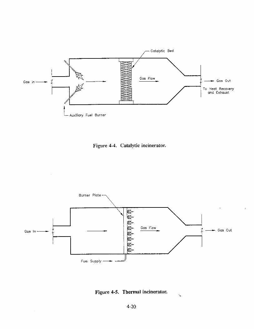
GQs In
L Auxiliary Fuel Burner
Catalytic Bed
Gas Flow__ Gas Out
To Heat Recovery and Exhaust
Figure 4-4. Catalytic incinerator.
Gas In
Burner Plate
Gas Flow Gas Out
Figure 4-5. Thermal incinerator.
4-20

acidic compounds such as HC1 or H.2SO 4.
These streams are likely to require removal of the acid
components by a scrubber unit, greatly adding to the cost of the VOC control system. 3° Catalytic
incinerators are very sensitive to materials that can reduce the effectiveness of the catalyst.
Phosphorous, lead, sulfur, and halogens can poison typical catalysts and severely affect their
performance. 33 If it is necessary to use catalytic incineration to control waste streams containing these materials, special catalysts or other measures must be employed. Liquid or solid particles that deposit on the catalyst and form a coating also reduce the catalyst's usefulness by preventing
contact between the catalyst and the VOC. 3z'3•
For safety reasons, both thermal and catalytic incinerators may require large amounts of
dilution air to reduce the VOC concentration in the emission stream. Heating the dilution air to
the ignition point of the VOC may be prohibitively expensive, particularly if a waste gas contains
entrained water droplets which must be vaporized and raised to combustion chamber
temperatures. However, it is unlikely that dilution air would be necessary at a paint and ink
facility due to the relatively low VOC concentrations typically encountered.
4.4•3.1 Thermal Incinerators
Thermal incinerators pass the emission stream through a combustion chamber where the
VOCs are burned at temperatures typically ranging from 700 ° to 1,300°C (1,300 ° to 2,370°F). •
Initially, burning is started with the assistance of a natural gas flame or similar heat source. If
the VOC in the emission stream has a sufficient heating value and concentration, ignition
temperatures can be sustained by the combustion of the VOC, and the auxiliary heat can be
turned off. If the ignition temperature cannot be maintained by combustion only, the auxiliary heat must be left on. Auxiliary heat can be provided by fuels such as natural gas, and from
recovery of heat released during combustion. The waste gases from the thermal incinerator are
usually vented to the atmosphere. Thermal incineration is widely used to control continuous, dilute VOC emission streams
with constituents from a number of compounds. Thermal incinerators can achieve VOC removal
efficiencies of 98 percent or greater depending on the design of the equipment. These
efficiencies may not be possible in cases where the inlet VOC concentration is less than
approximately 2,000 ppm. For inlet concentrations lower than 2,000 ppm, the performance of
an incinerator is more appropriately indicated as a maximum exit concentration of 20 ppmv. 3•
c•-92-0z 4-21
For safety considerations, VOC concentrations are usually limited to 25 percent of the lower
explosive limit (LEL) for the VOC. If the VOC concentration is higher in the waste gas, dilution
may be required. Packaged, single-unit thermal incinerators are available to control emission
streams with flow rates up to about 100,000 scfm. 33
Thermal incinerators, via combustion, remove particulates and other organics in addition
to VOCs, thus enhancing their utility] z
One paint manufacturing facility currently uses regenerative thermal incineration to control
odors and VOC emissions. 5 The contaminated gases enter the system through an upper ring-
shaped manifold. The air from this manifold is directed into inlet stoneware (i.e., ceramic) beds
which act as energy recovery chambers. As the gases pass through the ceramic beds towards the
incineration chamber, they are heated to a temperature nearing that of incineration. The VOC
present in the fumes will autoignite in the beds. Oxidation is completed in the central
incineration chamber where a gas or oil burner maintains a preset temperature. The purified air
then passes through
a second set of ceramic beds which absorb much of the gas's internal heat.
The flow is periodically reversed to continually feed the inlet stream to the hot bed. The energy
which is stored in the stoneware bed during the outlet mode is subsequently used to preheat inlet
gases. Thermal efficiencies can exceed 95 percent. Although capital costs are high, they are
generally offset by a decreased need for auxiliary fuels. 5'•8
4.4.3.2 Catalytic Incinerators
Catalytic incinerators are similar to thermal incinerators in that they eliminate VOCs from
the waste stream via combustion. The distinguishing feature of a catalytic incinerator is the
presence of a catalyst (such as platinum or copper oxide) that allows the VOC combustion
reaction to take place at a temperature lower than the normal ignition temperature exhibited by
the VOC in air. •x'•3 By allowing the combustion reaction to take place at lower temperatures than
required for a thermal incinerator, less preheating of the emission stream from auxiliary heat is
necessary, and significant fuel savings are achieved.
In the catalytic incinerator, the emission stream is preheated to approximately 320°C
(600°F) by recovered incinerator heat or by auxiliary burners. 3• The preheated emission stream
is passed through the catalyst bed where combustion takes place on the activated catalytic
surface. The incinerators are operated from 320 ° to 650°C (600 ° to 1,2,00°F), significantly lower
CH-92-02 4-22
than operating temperatures for thermal incinerators. Higher temperatures can shorten the life
of the catalytic bed. Properly operated catalytic converters can be satisfactorily operated for three
to five years before replacement of the catalyst is necessary. 33
Catalytic incinerators have been applied to emission streams in many industries. Packaged,
single-unit catalytic incinerators are available to control emission streams with flow rates up to
about 100,000 scfm at efficiencies greater than 98 percent. 32
Low energy costs make the catalytic incinerator an important option for removal of VOC
from emission streams; however, the catalytic incinerator cannot be used in as many applications
as the thermal incinerator. Catalytic materials can be quickly degraded by many elements or
compounds present in industrial emissions such as sulfur or particulates. Many of these materials
are burned without difficulty in thermal incinerators.
Some of the issues which must be addressed when applying catalytic incineration
techniques are the incinerator's ability to handle the large variety of vapor phase organics that
would be emitte•l from a paint and ink facility, the wide variety of organic concentrations in
process waste streams, and the changing speciation of organic emissions that would occur with
adjustments of paint and ink product formulations over time. • In many cases, one catalyst
cannot handle all of the waste stream variations encountered in paint and ink manufacturing
facilities.
4.4.3.3 Industrial Boilers and Process Heaters
In industrial boilers and process heaters, hot combustion gases (typically from natural gas
or fuel oils) are placed into contact with heat transfer tubes that contain water or process liquids.
Heat from the combustion gases is transferred across the tube to the liquids to produce steam or
to heat the process material. In addition to their function as steam generators and heaters,
industrial boilers and process heaters are currently used in industry to control organic emissions
from manufacturing operations. Both devices are most applicable where high heat recovery
potential exists. •1
Because the combustion of organic emissions can affect the performance of a boiler, the
emission characteristics must be considered. Such factors as variable flow rates, variable heat
contents, pressure, and the presence of corrosive compounds may require changes in the operation
of the boiler or heater. Boilers currently operating in a facility may nqt be able to control all of
4-23

the emissions from the plant, and an additional incineration device may be required. When a
new boiler or other incineration device is to be purchased, the operating and design parameters
can be calculated to fit specific facility needs. 3•'38
If a boiler or process heater is applicable and available for use as a control device, they
may provide excellent control efficiencies comparable to a thermal incinerator, while reducing capital and operating costs. The only capital investments involved are those associated with
capture system ductwork, fans, and boiler or process heater modifications required to direct
emissions to the boiler/process heater. One difficulty associated with boilers and process heaters
is that they must operate continuously and concurrently with the emission source unless other
control devices or strategies are available. 31'38
c•-•-o2 4-24

4.5 REFERENCES
1987 Census of Manufacturers. Industry Series. Paints and Allied Products. U.S. Department of Commerce. Washington, D.C.
1987 Census of Manufacturers. Industry Series. Miscellaneous Chemical Products. U.S.
Department of Commerce. Washington, D.C.
Title 35: Environmental Protection, Subtitle B: Air Pollution, Chapter I: Pollution Control Board, Subpart AA: Paint and Ink Manufacturing, Section 215.624. Rules and Regulations, Illinois Environmental Protection Agency.
4. ICI trip report and facility information.
5. PPG trip report and facility information.
6. Perry & Derrick trip report and facility information.
Borden trip report and facility information.
Titman, H.,: "A review of Experiments on the Ignition of Inflammable Gases by Frictional Sparking," Transactions of the Institution of Mining Engineers, 115(7):536-557, 1956.
Memo from Glanville, J. and S. Edgerton, Midwest Research Institute, to Magnetic Tape Project File, Project 83/18, U.S. Environmental Protection Agency, Emission Standards Division, Office of Air Quality Planning and Standards. December 17, 1986. Calculated Control Efficiency of Covers on Mix Tanks.
10.
11.
U.S. Environmental Protection Agency. Polymeric Coating of Supporting Substrates-- Background lnforrnation for Promulgated Standards, EPA-450/3-85-022b. Office of Air Quality Planning and Standards. Research Triangle Park, NC. 1989.
Zoga, Christ, "Horizontal Media Milling With Computer Controls," reprinted from Modern Paint and Coatings, by Premier Mill Corporation, New York, NY. June 1984.
12. Sneeringer, John R., "Consider the Horizontal Mill," reprinted from CPIIO0, by Premier Mill Corporation, New York, NY May/June 1986.
13. U.S. Environmental Protection Agency. Guides to Pollution Prevention: The Paint Manufacturing Industry, EPA-625/"/-90-005. Risk Reduction Engineering Laboratory. Cincinnati, OH. 1990.
14. Jacobs Engineering Group, Inc. Waste Audit Study: Paint Manufacturing Industry, prepared for Toxic Substances Control Program, California Department of Health Services. April 1989 revision of original study report.
ca-9z-oz 4-25

15.
16.
19.
20.
21.
22.
23.
24.
25.
26.
27.
Quackenbush, Ivan C., "Points on Picking the Right Media for Small-Media Mills," reprinted from American Paint & Coatings Journal for the Quackenbush Company. December 13, 1982.
"Bugs? In your Bead Mill," eleventh printing. Pamphlet from the Quackenbush Company, Palatine, IL, 1985.
Permit information retrieved from the State of Ohio Environmental Protection Agency.
U.S. Environmental Protection Agency. Surface Coating of Metal Furniture-Background Information for Proposed Standards. EPA-450/3-80-007a. Office of Air Quality Planning and Standards. Research Triangle Park, NC. 1980.
"Powder Coatings," pamphlet prepared for The Powder Coating Institute, Alexandria, VA, 1990.
Bocchi, Greg, "Powder Coating Advantages," reprinted from: Products Finishing for The
Powder Coating Institute, Gardner Publications, Inc, 1991.
"Powder Coatings Bloom," Chemical Marketing Reporter, 240(8): 9,12, 1991.
"Coating Materials," pamphlet no.: TD 100-5, BINKS Training Division, Franklin Park, IL.
Pennsylvania Department of Environmental Resources. Hazardous Waste Minimization
Guidance Manual for Pennsylvania's Vehicle Maintenance Industry. Center for Hazardous
Materials Research. Pittsburgh, PA. 1987.
U.S. Environmental Protection Agency. Radiation-Curable Coatings. EPA-600/2-91-035. Con•:ol Technology Center. Research Triangle Park, NC. 1991.
Kohl, Jerome, Jeremy Pearson, Michelle Rose, and Philip Wright, "Managing and
Recycling Solvents in the Furniture Industry," reprinted for Pollution Prevention Pays Program, January 1988.
Brantley, Michael, "Volatile Organic Compound ('VOC) Emission Implementation," from the Proceedings of Finishing, '89 Conference, Manufacturing Engineers, Oct. 16-19, Cincinnati, OH, 1989.
Reduction Society of
U.S. Environmental Protection Agency. Glossary for Air Pollution Control of Industrial Coating Operations, EPA-450/3-83-013R. Second Edition. Office of Air Quality Planning and Standards. Research Triangle Park, NC. 1983.
cH-gz-0Z 4-26
28.
29.
30.
31.
32.
33.-
36.
37.
38.
Ross, Vincent, "Waste Reduction-Pollution Prevention in the Furniture Industry: New Technologies for Reducing Finishing Wastes and VOC Emissions," Proceedings of the Conference "Waste Reduction-Pollution Prevention: Progress and Prospects within North Carolina." North Carolina Department of Natural Resources and Community Development. 1990.
Roos, R.A., G.R Fenton, and R.W. Perryman. "Containment of Fumes and Vapors Generated in the Aluminum Rolling Process" in Lubrication Engineering, Volume 40., No. 10. pp. 621-626. American Society of Lubrication Engineers. October 1984.
OAQPS Control Cost Manual. EPA-450/3-90-006. Fourth Edition. Office of Air Quality Planning and Standards, Research Triangle Park, NC. January 1990.
Control Techniques for Volatile Organic Compound Emissions fi'om Stationary Sources. EPA-450/3-85-008. Third Edition. Office of Air and Radiation and the Office of Air Quality Planning and Standards. Research Triangle Park, NC. 1986.
Radanof, R.M. "VOC Incineration and Heat Recovery-Systems and Economics" in Third Conference on Advanced Pollution Control for the Metal Finishing Industry. EPA-600/2- 81-028. .U.S. Environmental Protection Agency, Industrial Environmental Research Laboratory. Cincinnati, OH. February 1981.
Handbook: Control Technologies for Hazardous Air Pollutants. EPA-625/6-86-014. Air and Energy Engineering Research Laboratory. Research Triangle Park, NC. September 1986.
Cleveland RACT Document, PPG Industries, Inc., Cleveland, OH. July 1987.
Ehrler, A.J. "Closed-Loop Absorption for Solvent Recovery" in Metal Finishing, Volume 85, No. 11. pp. 53-56. November 1987.
Heim, C.J., "Volatile Organic Emission Control in the Aluminum Industry Using Fluidized Bed Carbon Adsorption," Proceedings of the Workshop on Characterization and Control of Aluminum Cold Rolling Mill Emissions, The Aluminum Association. 1983.
Batten, A.E. "A New System for Separation and Recycling of Mineral Oils from Process Fumes," in Lubrication Engineering, Volume 38, No. 12. pp. 754-757. American Society of Lubrication Engineers. December 1982.
U.S. Environmental Protection Agency. Control of VOC Emissions from Polystyrene Foam Manufacturing, EPA-450/3-90-020. Office of Air Quality Planning and Standards. Research Triangle Park, NC. 1990.
•.gz-oz 4-27

CHAPTER 5
CONTROL COST ANALYSIS
5.1 INTRODUCTION
This chapter presents the estimated costs for controlling VOC emissions from paint and ink
manufacturing facilities. The VOC reduction methods discussed in Chapter 4 are summarized
in Table 5-1, along with their applicability and current use in paint and ink manufacturing
industries. Of the methods presented in Table 5-1, the following are both applicable and used
by paint and ink manufacturing plants for reducing emissions: tank lids, horizontal media mills,
equipment cleaning devices, improved operating practices, recycling techniques, product
reformulation, capture devices, and thermal incinerators. These methods are presented with their
available associated costs in subsequent sections in this chapter.
5.2 EQUIPMENT OR PROCESS MODIFICATIONS
Tank lids, horizontal media mills, and equipment cleaning devices all reduce VOC
emissions by modifying manufacturing equipment.
5.2.1 Equipment Tank Lids
The most common method of controlling VOC emissions during the paint and ink
manufacturing process is the use of equipment tank lids. Mix and blend tanks are a primary
source of manufacturing VOC emissions because the solvent-containing materials spend a
significant amount of time in this equipment. All of the States that regulate paint and ink
manufacturing facilities require that all open-top equipment be covered during the manufacturing
process. In most cases, the State or local agencies have adopted rules defining process controls,
such as lids, as RACT for paint and ink manufacturing industries (See Tables 3-2 and 3-3).
Lids reduce VOC emissions by retaining the solvent in the product in the mix tank. This
action serves to keep the product fluid and workable, thus preventing future solvent additions.
cH-9z-oz 5-1

TABLE 5-1. APPLICABILITY AND USE OF VOC EMISSION REDUCTION METHODS IN PAINT AND INK FACILITIES
Reduction Method Applicability to Industry Current Use in Industry
Tank Lids Used extensively Most facilities
Horizontal Media Mills
Equipment Cleaning Devices (rubber wipers, high-pressure spray heads, Teflon lined tanks, pigs, automatic tub washers)
Improved Operating Practices
Considered by States as
RACT Not normally vented to control devices
Require low viscosity products Highly efficient, closed milling system
Efficiency of use depends on
product manufactured and level of employee training Some installations may require equipment modifications
Used extensively
Recycling Techniques
Product Reformulation
Used extensively Applicability depends on end
use and customer requirements Some States have regulations requiring lower VOC coatings Reformulation requires extensive research and development
Some facilities
Some facilities
Most facilities
Most facilities
Many facilities
Capture Devices Applicable according to data collected from other similar industries Capture devices are
commonly used for particulate control
Extent of use is unknown. Only one facility with documented use.
(Continued)
5-2

TABLE 5-1. APPLICABILITY AND USE OF VOC EMISSION REDUCTION METHODS IN PAINT AND INK FACILITIES (continued)
Reduction Method Applicability to Industry Current Use in Industry
Carbon Adsorbers Not applicable to industry Few facilities" because of low VOC inlet concentrations and variety of contaminants in wastestream
Not applicable to industry because of costs associated with low VOC inlet concentrations May be used by very specialized plants
Absorbers Few facilities"
Condensers
Thermal Incinerators
Catalytic Incinerators
Industrial Boilers and Process Heaters
Few facilities" Not applicable to industry because of efficiency and
costs associated with waste-
stream concentration and composition variability May be used in very specialized plants Applicable, capable of Few facilities" destroying contaminants in
process wastestreams
Not applicable to industry because of low VOC inlet concentrations and variety of contaminants in wastestream
Applicable according to data collected from other similar industries
No documented use found
No documented use found
"Few Documentation shows use by less than 20 facilities.
5-3
Lids also reduce excess VOC emissions entering the work area. Because the primary objective
of tank lids is to keep the solvent in the product, ducting lids to control devices •.s uncommon.
The lids that are currently used in industry for covering process mix tanks can be either
plastic, wooden, aluminum, or stainless steel. 1-• Plastic lids consist of a thin sheet of plastic
which is placed across the tank in question and then taped or otherwise attached to the side of
the tank. Normally, plastic lids are used for one product batch and then are thrown away. Other
facilities use homemade plywood lids. After several uses, the underside of the plywood becomes
saturated with product and the lid must be discarded. The most frequently used lids are those
constructed of either aluminum or stainless steel. Flat aluminum lids, which are made by a sheet
metal contractor, cost $20 to $25 for drums and $300 for a 250 gallon mix tank. Similar
stainless steel lids often cost twice as much as the aluminum lids) The efficiency of mixer lids
has been estimated to be approximately 40 percent (See discussion of lid efficiency in Chapter
4). s This value represents the ratio of the emission reduction to the uncontrolled emissions.
Using the lid efficiency of 40 percent, assuming an average batch size of 250 gallons, and
employing some additional data from the PPG R.ACT study (discussed below), the cost efficiency
of equipment lids can be determined as indicated in Table 5-2.
As part of their RACT determination, the PPG facility determined total VOC emissions
released from each of their manufacturing buildings. 6 In 1983, Building 19 used nine portable
mix tanks with agitators to accomplish premix operations. During that year, the tanks emitted
25 tons of VOC to the atmosphere. Assuming a normal operating schedule of 24 hours a day,
5 days per week, and 52 weeks per year, this calculates to approximately 0.89 pound of VOC
per hour from each tank. 1'6 This factor is specific to the PPG facility and its product•, as
emission rates will vary with many factors including the type of product manufactured, the type
of solvent used, and the capacity of the manufacturing equipment.
5.2.2 Horizontal Media Mills
Installing horizontal media mills is a second way to reduce VOC emissions generated
during the manufacturing process. Although these mills are more efficient milling devices than
mix tanks and can be considered nearly 100 percent effective in controlling VOC emissions, they
cannot be used to manufacture every type of paint and ink.
CH-92-02 5-4

TABLE 5-2. EQUII•MENT COVER COST FIGURES
Cost Item (in dollars) Number Cost Total Cost
Aluminum equipment covers 9 300 2,700 (replaced annually)
Cost Efficiency Total Annualized Operating Cost for Equipment Lids
Total Emissions 25 tons/year at 40% control efficiency 10 tons/year
Cost Efficiency
2,700
$270•on •Cost figures and were taken from References 1, 2, and 6 and are assumed to be current dollars.
ca-groz 5-5

A typical 15 liter horizontal media mill with a 20 horsepower motor can produce 13 to 78
gallons of product per hour depending on the type of product produced. 7 With an average
production capacity of 50 gallons per hour, a horizontal mill will produce 250 gallons of product
in 5 hours. Similar production quantifies in other equipment may take 15 hours of processing
time. These numbers would indicated that horizontal media mills are approximately three times
as efficient as other equipment (e.g., a 250 gallon mix tank equipped with a high-speed disperser
or a 15 liter open-top sandmill). 1'2'8
Table 5-3 presents cost information for a horizontal media mill. To determine the cost
effectiveness of the process change as a control measure, the annual cost of the control equipment
(or mills) it replaces must first be subtracted from the cost of a horizontal mill. This incremental
cost divided by the amount of VOC emissions reduced would indicate the cost effectiveness of
the process change.
5.2.3 Equipment Cleaning Devices
Many equipment cleaning processes performed in the paint and ink manufacturing industry
use organic solvents as the cleaning agent. Although equipment cleaning is a major source of
VOC emissions, it is difficult to determine the overall efficiency or impact that equipment
cleaning devices have on reducing VOC emissions from equipment cleaning processes because
no data is available which quantifies these process emissions. Therefore, an equipment cost
efficiency cannot be calculated.
5.3 VOC EMISSION REDUCTION METHODS
Two additional methods which may be used to reduce VOC emissions during the
manufacturing process are improving operating practices and recycling. Discussions of both of
these methods are included in Chapter 4. Both of these techniques are very popular within the
paint and ink manufacturing industry because they are easily implemented at low cost. The only
costs involved with either of these techniques are those for operator training. In retum, solvent
emissions and waste can be significantly decreased. One manufacturer of trade sales paints in
CH-92-02 5-6
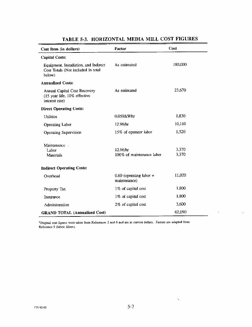
TABLE 5-3. HORIZONTAL MEDIA MILL COST FIGURES
Cost Item (in dollars) Factor Cost
Capital Costs:
Equipment, Installation, and Indirect Cost Totals (Not included in total below)
Annualized Costs:
Annual Capital Cost Recovery (15 year life, 10% effective interest rate)
Direct Operating Costs:
Utilities
Operating Labor
Operating Supervision
Maintenance Labor Materials
Indirect Operating Costs:
Overhead
Property Tax
Insurance
Administration
GRAND TOTAL (Annualized Cost)
As estimated 180,000
As estimated 23,670
0.059/kWhr 1,830
12.96/hr 10,110
15% of operator labor 1,520
12.96/hr 3,370 100% of maintenance labor 3,370
0.60 (operating labor + 11,020 maintenance)
1% of capital cost 1,800
1% of capital cost 1,800
2% of capital cost 3,600
62,090
"Original cost figures were taken from References 2 and 6 and are m current dollars. Factors are adapted from
Reference 9 (fabric filters).
cr•-gz-0z 5-7
North Carolina reduced waste solvent production from 25,000 gallons to 400 gal!ons in the
course of a year by implementing a recycling program. In addition to redu::ing ultimate
hazardous waste disposal costs, the faci.lity also reduced the amount of virgin solvent purchased) °
These actions, in turn, will reduce overall emissions.
5.4 PRODUCT REFORMULATION
It is extremely difficult to assess the costs associated with product reformulation. The
primary cost is the research and development that is required by each facility to reformulate
current products using lower VOC raw materials. Although waterbornes, powders, radiation-
curables, and higher-solids formulations are currently available, they may not meet the specific
end-user requirements and needs. In addition to absorbing development costs, industries wishing
to reformulate must also invest in pilot studies, product testing, and additional operator training.
Reformulated co•tings often act differently than solvent based products and require increased
levels of process control. I°
5.5 CAPTURE DEVICES
According to data collected from the polymeric coating industry and from the Cleveland
PPG facility, capture devices are expected to be applicable to the paint and ink manufacturing
industry) "xl However, only one paint facility is known to have a plant-wide capture system and
the capiUd and operating costs for this facility are unavailable. 6 The costs associated with a
complete capture system are relatively inexpensive when compared to those of a control device.
5.6 THERMAL INCINERATION •'6
The costs associated with thermal incineration presented here are based on actual costs
incurred by one facility known to employ thermal incineration as their control technique. The
costs are based on purchase, installation, and operation of two thermal incinerators at the
Cleveland PPG Industries, Inc., facility. One incinerator, the REECO I, controls VOC emissions
from the manufacturing facility. A second REECO incinerator, REECHO II, controls emissions
cwgz-oz 5-8

from the PPG paint laboratory also located at the Cleveland site. Both of the nine-chamber fume
incinerators were originally installed as odor control devices.
The 95 percent destruction and removal efficiency of the incinerators depends on the
capture efficiency of the ventilation system. A study conducted in 1983 indicated that plantwide
emissions for the Cleveland facility are 1,085.9 tons per year. Of these releases, 25 tons per year
are lost to the atmosphere. This represents a fugitive emission capture efficiency of
approximately 96 percent. The capital and operating costs and cost efficiency for thermal
incineration at the Cleveland PPG facility are presented in Table 5-4.
c•.9•o• 5-9

TABLE 5-4. CLEVELAND FACILITY THERMAL INCINERATION COST FIGURES
Cost Item (in dollars) REECO I REECO H Total
Capital Costs:
Equipment, Installation, and Indirect 7,071,760 5,407,975 12,479,735 Cost Totals (Not included in total below)
Annualized Costs:
Annual Capital Cost Recovery 1,150,897 880,123 2,031,020 (10 year life, 10% effective interest rate)
Direct Operating Costs:
Utilities 522,888 530,430 1,053,318
Operating Labor 25,666 25,666 51,332
Operating Supervision 3,827 3,827 7,654 (based on 15% of operator labor)
Maintenance Contracted: Labor 16,886 16,886 33,772 Materials 16,886 16,886 33,772
Indirect Operating Costs:
Overhead 20,488 20,488 40,976
Property Tax (pollution -0- -0- -0-
abatement equipment is exempt)
Insurance (1% of capital cost) 70,700 54,000 124,700
Administration (2% of capital 141,400 108,200 249,600 cost)
GRAND TOTAL 1,969,638 1,656,506 3,626,144
Cost Efficiency: Total Annualized Operating Cost for Incinerators
Total Emissions: 1085.9 tons/year at an overall efficiency of 91.2% 990.3 tons/year
Cost Efficiency:
3,626,144
$3,662Ron
'Original cost figures were taken from Reference and are assumed to have been 1987 dollars. The costs were then adjusted to 1992
dollars using published Chem&al Engineering cost indices.
ca-gz-0z 5-10

5.7 REFERENCES
2.
3.
4.
5.
10.
11.
PPG trip report and facility information.
ICI trip report and facility information.
Perry & Derrick trip report and facility information.
Borden trip report and facility information.
Memo from Glanville, J. and S. Edgerton, Midwest Research Institute, to Magnetic Tape Project File, Project 83/18, U.S. Environmental Protection Agency, Emission Standards
Division, Office of Air Quality Planning and Standards. December 17, 1986. Calculated
Control Efficiency of Covers on Mix Tanks.
Cleveland RACT Document, PPG Induslries, Inc., Cleveland, OH. July 1987.
"Superrnill." Product pamphlet from the Premier Mill Corporation, New York, NY.
Zoga, Christ, "Dispersion and Milling Methods to Increase Plant Productivity," reprinted from Modern Paint and Coatings, by Premier Mill Corporation, New York, NY. May 1989.
U.S. Environmental Protection Agency. Handbook: Control Technologies for Hazardous
Air Pollutants, EPA-625/6-91-014. Office of Research and Development. Washington, DC. June 1991.
Kohl, Jerome, Phillip Moses, and Brooke Triplett. Managing and Recycling Solvents.
North Carolina Practices, Facilities, and Regulations. December 1984.
U.S. Environmental Protection Agency. Polymeric Coating of Supporting Substrates-- Background Information for Promulgated Standards, EPA-450/3-85-022b. Office of Air
Quality Planning and Standards. Research Triangle Park, NC. 1989.
ca-9z-oz 5-11


APPENDIX A
LISTS OF FACILITIES WITH ANNUAL SALES GREATER THAN $1 MILLION
CH-9•O• A-1


TABLE A-1. PAINT AND ALLIED PRODUCTS FACILITIES (SIC 2851) WITH ANNUAL SALES GREATER THAN $1 MILLION
Sales in Name Address $ Millions
Aervoe-Pacilic Co. Inc. AExcel Corp. Agri-Blend Inc. Akron Paint & Varnish Inc.
Akzo Coatings Inc. Reliance Universal Inc.
Akzo Coatings Inc. Akzo Resins & Vehicles
Akzo Coatings Inc.
Allentown Paint Manufacturing Co.
Also Indus Inc. Morton Paint Co.
Ameritone Paint Corp. Ameron Inc. Enmar Finishes Div.
Ameron Inc. Ameron Protective Coatings Div.
Amsterdam Color Works Inc.
Aspen Paints Atlas Coating Corp.: Automotive Finishes Inc.
Baker Sealants & Coating Barrett Varnish Co.
Bee Chem Co.
Behr Process Corp. Benjamin Moore & Co.
Bennette Paint Manufacturing Co.
Best Bros Paint Manufacturing Co.
Beverly Manufacturing Co. (Los Angeles) Birk Paint Manufacturing Inc.
Blue Ridge Talc Co. Inc.
Brewer Chem Corp. Brod-Dugan Co. Bruning Paint Co.
Burkes Paint Co. Inc.
Buten Paint & Wallpaper Cabot Stains Cal Western Paint Corp. Calbar Inc. California Products Corp. Carbit Paint Co. Carboline Co. Cardinal Color Co. Cardinal Indus Finish Inc.
Century Chem Co.
1'O Box 485, Gardnerville NV 89410 7373 Production Dr, Mentor OH 44060 PO Box 957, Rowlett TX 75088 1390 Firestone Parkway, Akron OH 44301 1930 Bishop Ln, Louisville KY 40218 21625 Oak St, Matteson IL 60443 1600 Watterson Towers, Louisville KY 40218 PO Box 597, Allentown PA 18105
Box 6208, Canton OH 44706 PO Box 190, Long Beach CA 90801 PO Box 9610, Little Rock AR 72219 201 N Berry St, Brea CA 92621
1546 Stillwell Ave, Bronx NY 10461 1128 SW Spokane St, Seattle WA 98134 820 E 140th St, Bronx NY 10454 6430 Wyoming Ave, Dearborn MI 48126 234 Suydam Ave, Jersey City NI 07304 1532 S 50th Ct, Cicero lL 60650 2700 E 170th St, Lansing IL 60438 PO Box 1287, Santa Aria CA 92702 51 Chesmut Ridge Rd., Montvale NJ 07645
PO Box 9088, Hampton VA 23670 PO Box 2056, Sinking Spr PA 19608 9118 S Main St, Los Angeles CA 90003 230 Kearny Ave, Jersey City NJ 07305 PO Box 39, Henry VA 24102 PO Box 48, Honolulu HI 96810 2145 Schuetz Rd, St. Louis MO 63146 601 S Haven, Baltimore, MD 21224
727 S 27th St, Washougal WA 98671 5000 Ridge Ave, Philadelphia PA 19128 100 Hale St, Newburyport MA 01950 11748 Slauson Ave, Santa Fe Spr CA 90670 2626 N Martha St, Philadelphia PA 19125 PO Box 569, Cambridge MA 02139 927 W Blackhawk St, Chicago IL 60622 350 Hanley Indus Ct, St. Louis MO 63144 50-56 1st St, Paterson NJ 07524 1329 Potrem Ave, South El Mon CA 91733 5 Lawrence St, Bloomfield NJ 07003
11 20 1" 4*
300 13
550* 4
3 40 15
112
7 4
7* 4 5 3
66 33*
370* 5 1 2 2 9
5O 15 30
3 4O 30
5 4
32 5
65 7
18 5
(continued)
ca-9"z-o• A-2

TABLE A-1. PAINT AND ALLIED PRODUCTS FACI].,ITIES (SIC 2851) WITH ANNUAL SALES GREATER THAN $1 MILLION (continued)
Sales in
Name Address $ Millions
Certified Coating Products
CF Jameson & Co. Inc.
Charles A Crosbie Labs Inc.
Chemical Technology Labs Inc.
Chemical Coating Corp. Ciba-Geigy Corp. Drakenfeld Colors
Clement Coverall Inc.
CM Athey Paint Co.
Coatings & Chems Corp. Colonial Refining & Chem Co.
Columbia Paint Corp. Columbia Paint Co.
Colwell Gen Inc. Commercial Chem Co. Inc.
Con-Lux Coatings Inc.
Cook & Dunn Paint Corp. Pure All Paint Coatings Co.
Cook & Dunn Paint Corp. Cook & Dunn Paint Corp. Adelphi
Coating Cook Paint & Varnish Co.
Coronado Paint Co. Inc.
Cosan Chem Corp. Cotter & Co. Gen Paint & Chem Co.
Courtlaulds Coatings USA Inc.
Cowman & Campbell CP Inc. Crest Chem Indus Ltd.
Crosby Coatings Inc.
CWC Indus Inc.
Dalys Inc.
Dampney Co. Inc.
Daniel Products Co.
Davis Paint Co. Davlin Paint Co. Inc.
DC Franche & Co.
De Boom Paint Co.
Dean & Barry Co. Decratrend Paints Deft Inc.
2414 S Connor Ave, Los Angeles CA 90040
PO Box 197, Bradford MA 01835 PO Box 3497, Van Nuys CA 91407 12150 S Alameda St, Lynwood CA 90262 7300 Crider Ave, Pico Rivem CA 90660 PO Box 519, Washington PA 15301 PO Box 557, Camden NJ 08101 1809 Bayard St, Baltimore MD 21230 3067 N Elston Ave, Chicago IL 60618 20575 Ctr Ridge Rd, Cleveland OH 44116
PO Box 2888, Huntington WV 25728 PO Box 4569, Spokane WA 99202 PO Box 329, Fort Wayne IN 46801 PO Box 2126, Santa Ana CA 92707
PO Box 847, Edison NJ 08818 700 Gotham Ave, Carlstadt NJ 07072
700 Gotham Parkway, Carlstadt NJ 07072 700 Gotham Parkway, Carlstadt NJ 07072
PO Box 419389, Kansas City MO 64141 PO Box 308, Edgewater FL 32032 400 14th St, Carlstadt NJ 07072 201 Jandus Rd., Cary IL 60013
PO Box 1439, Louisville, KY 40201 1'O Box 70328, Seattle WA 98107 PO Box 333, Connersville IN 47331 PO Box 85, New Lenox IL 60451 PO Box 1038, Chico CA 95927 2686 Lisbon Rd, Cleveland OH 44104
3525 Stone Way N, Seattle WA 98103 85 Paris St, Everett MA 02149 400 Claremont Ave, Jersey City NJ 07304 1311 Iron St, Kansas City MO 64116 700 Allston Way, Berkely CA 94702 1401 W Wabansia Ave, Chicago IL 60622 645 Texas St, San Francisco CA 94107 296 Marconi Blvd, Columbus OH 43215
251 Mason Way, City of Indu CA 91746 17451 Von Karman Ave, Irvine CA 92714
1
1 1 3 3
28 4 6 5 3 5
17 20 4
25 8*
2O 3
100 28 i0" 120 160"
3
1" 6 5 5 4
20 13 3* 3 5
15 17 15
(continued)
ca-9"z-oz A-3
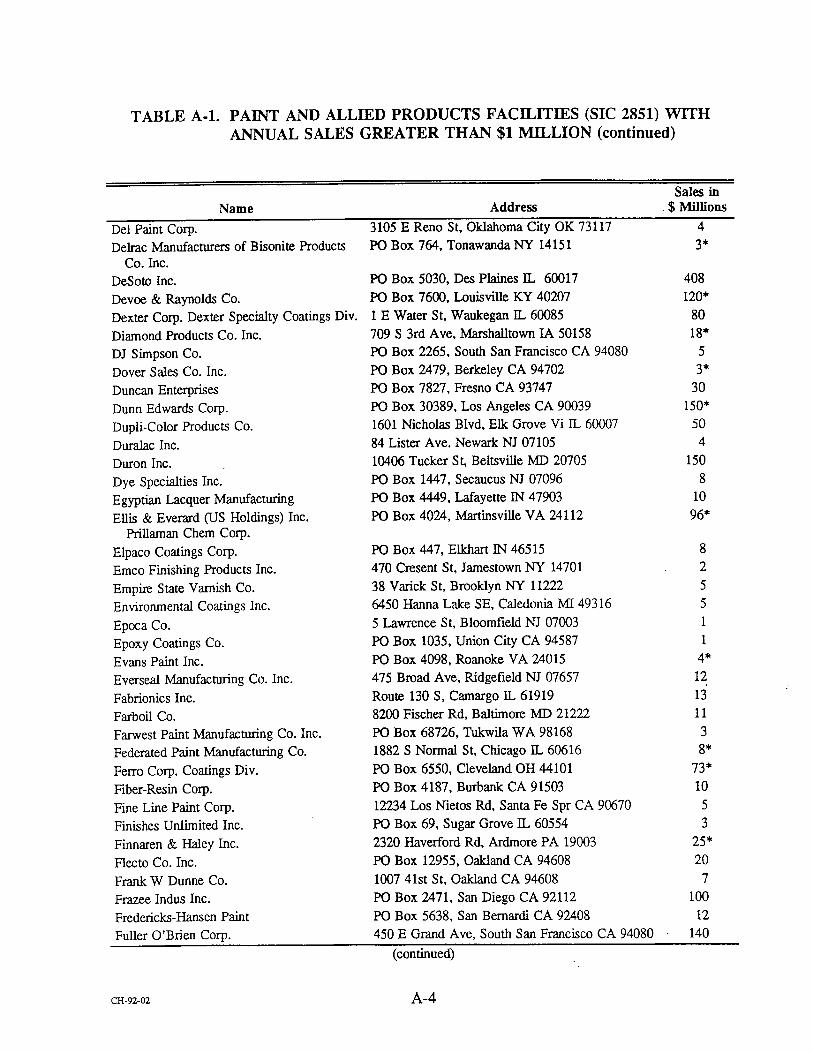
TABLE A-1. PAINT AND ALLIED PRODUCTS FACII•ITIES (SIC 2851) WITH ANNUAL SALES GREATER THAN $1 MILLION (continued)
Sales in
Name Address $ Millions
Del Paint Corp. 3105 E Reno St, Oklahoma City OK 73117 4
Delrac Manufacturers of Bisonite Products PO Box 764, Tonawanda NY 14151 3* Co. Inc.
DeSoto Inc. 408
Devoe & Raynolds Co. 120"
Dexter Corp. Dexter Specialty Coatings Div. 80
Diamond Products Co. Inc. 18"
DJ Simpson Co. 5
Dover Sales Co. Inc. 3*
Duncan Enterprises 30
Dunn Edwards Corp. 150"
Dupli-Color Products Co. 50
Duralac Inc. 4
Duron Inc. 150
Dye Specialties Inc. 8
Egyptian Lacquer Manufacturing 10
Ellis & Everard (US Holdings) Inc. 96* Prillaman Chem Corp.
Elpaco Coatings Corp. 8
Emco Finishing Products Inc. 2
Empire State Varnish Co. 5
Environmental Coatings Inc. 5
Epoca Co. 1
Epoxy Coatings Co. 1
Evans Paint Inc. 4*
Everseal Manufacturing Co. Inc. 12
Fabrionics Inc. 13
Farboil Co. i 1
Farwest Paint Manufacturing Co. Inc. 3
Federated Paint Manufacturing Co. 8*
Ferro Corp. Coatings Div. 73*
Fiber-Resin Corp. 10
Fine Line Paint Corp. 5
Finishes Unlimited Inc. 3
Finnaren & Haley Inc. 25*
Flecto Co. Inc. 20
Frank W Dunne Co. 7
Frazee Indus Inc. 100
Fredericks-Hansen Paint 12
Fuller O'Brien Corp. 140
PO Box 5030, Des Plaines IL 60017 PO Box 7600, Louisville KY 40207 1 E Water St, Waukegan ]:L 60085 709 S 3rd Ave, Marshalltown IA 50158 PO Box 2265, South San Francisco CA 94080 PO Box 2479, Berkeley CA 94702 PO Box 7827, Fresno CA 93747 PO Box 30389, Los Angeles CA 90039 1601 Nicholas Blvd, Elk Grove Vi IL 60007
84 Lister Ave. Newark NJ 07105 10406 Tucker St, Beltsville MD 20705 PO Box 1447, Secaucus NJ 07096 PO Box 4449, Lafayette IN 47903 PO Box 4024, Martinsville VA 24112
PO Box 447, Elkhart IN 46515 470 Cresent St, Jamestown NY 14701
38 Varick St, Brooklyn NY 11222 6450 Hanna Lake SE, Caledonia MI 49316
5 Lawrence St, Bloomfield NJ 07003 PO Box 1035, Union City CA 94587 PO Box 4098, Roanoke VA 24015 475 Broad Ave, Ridgefield NJ 07657
Route 130 S, Camargo IL 61919 8200 Fischer Rd, Baltimore 1VID 21222
PO Box 68726, Tukwila WA 98168 1882 S Normal St, Chicago ]L 60616 PO Box 6550, Cleveland OH 44101 PO Box 4187, Burbank CA 91503 12234 Los Nietos Rd, Santa Fe Spr CA 90670 PO Box 69, Sugar Grove IL 60554 2320 H_averford Rd, Ardmore PA 19003 PO Box 12955, Oakland CA 94608 1007 41st St, Oakland CA 94608 PO Box 2471, San Diego CA 92112 PO Box 5638, San Bemardi CA 92408 450 E Grand Ave, South San Francisco CA 94080
(continued)
CI-[-92-02 A-4

TABLE A-1. PAINT AND ALLIED PRODUCTS FACILITIES (SIC 2851) WITH ANNUAL SALES GREATER THAN $1 MILLION (continued)
Sales in
Name Address $ Millions
Gilbert Spruance Co.
Given Paint Manufacturing Co. Inc.
GJ Nikolas & Co. Inc.
Glidden Co. Eastern Region Glidden Co. Southwest Region Glidden Co. Resin Div.
Gloss-Flo Corp. Glyptal Inc.
Gordon Bartels Co. Graham Paint & Varnish Co.
Grow Group Inc. US Paint Div.
Grow Group Inc. Nail Aerosol Products Co.
Grow Group Inc.
Guardsman Products Inc.
Guardsman Chems inc. H Behlen & Brother Inc.
Hancock Paint & Varnish
Hanna Chem Coatings Inc.
Harco Chem Coatings Inc.
Harrison Paint Corp. Hartin Paint & Filler
Hempel Comings US A
Hentzen Coatings Inc.
Heresite Protective Coatings Inc.
Hoboken Paint Co. Inc.
Hoffers Inc.
Hy-Klas Paints Inc.
Hydrosol Inc.
ICI Americas Inc. ICI Paints
Illinois Bronze Paint Co.
Indurall Coatings Inc.
Indusu-ial Coatings Intl.
Insilco Corp. Sinclair Paint Co.
International Paint Co. USA Inc.
International Paint Co. USA Inc. Southwest Div.
International Coatings Co.
Irathane Syss Inc.
IVC Indus Coatings Inc.
J Landau & Co. Inc.
Richmond St & Tioga St, Philadelphia PA 19134 10
111 N Piedras St, E1 Paso "IX 79905 7*
2810 Washington Blvd, Bellwood IL 60104 2
PO Box 15049, Reading PA 19612 140
PO Box 566, Carrollton TX 75011 59
1065 Glidden St NW, Atlanta GA 30318 30
135 Jackson St, Brooklyn NY 11211 4
305 Eastern Ave, Chelsea MA 02150 5
2600 Harrison Ave, Rockford IL 61108 7
4800 S Richmond St, Chicago IL 60632 10"
831 S 21st St, St. Louis MO 63103 30*
2193 E 14th St, Los Angeles CA 90021 5
200 Park Ave, New York NY 10166 413
3033 Orchard Vista Dr, Grand Rapids MI 49501 190
13535 Monster Rd, Seattle WA 98178 6
Route 30 N Perth Rd, Amsterdam NY 12010 10
109 Accord Dr, Norwell MA 02061 10
PO Box 147, Columbus OH 43216 25
208 DuPont St, Brooklyn NY 11222 6
PO Box 8470, Canton OH 44711 20
PO Box 116, Carlstadt NJ 07072 3
201 Route 17 N, Rutherford NJ 07070 15
6937 W Mill Rd, Milwaukee WI 53218 12
PO Box 250, Manitowoc WI 54221 15
40 Indus Rd, Lodi i'qI 07644 17
PO Box 777, Wausau WI 54401 47
1401 S 12th St, Louisville KY 40210 • 8407 S 77th Ave, Bridgeview IL 60455 30
925 Euclid Ave, Cleveland OH 44115 843
300 E Main St, Lake Zurich IL 60047 25
PO Box 2371, Birmingham AL 35201 8
7030 Quad Ave, Baltimore MD 21237 14"
6100 S Garfield Ave, Los Angeles CA 90040 100"
6001 Antoine, Houston TX 77091 50
PO Box 920762, Houston TX 77292 18
13929 E 166th St, Cerritos CA 90701 PO Box 276, Hibbing MN 55746 PO Box 18163, Indianapolis IN 46218
PO Box 135, Carlstadt NJ 07072
5 8* 9 4
(continued)
cw•-oz A-5

TABLE A-1. PAINT AND ALLIED PRODUCTS FACILITIES (SIC 2851) WITH ANNUAL SALES GREATER THAN $1 MILLION (continued)
Sales in
Name Address $ Millions
James B Day & Co.
James Bute Co.
Jasco Chem Corp. John L Armitage & Co.
Johnson Paints Inc.
Iones Blair Co. Gilman Paint & Wallcovering Div.
Kalcor Coatings Co.
Kaufman Products Inc.
Keeler & Long Inc.
Kelly-Moore Paint Co. Inc. Hurst Div.
Kelly-Moore Paint Co.
King Fiber Glass Corp. Fiber Resin Supply Div.
Komac Paint Inc.
Kop-Coat Co. Inc.
Kop-Coat Co. Inc. Pettit Paint Co.
Kurfees Coatings Inc.
Kwal-Howelis Inc.
L & H Paint Products Inc.
Lasting Paints Inc.
Lenmar Inc.
Lilly Chem Products Inc.
Lilly Industrial Comings Inc.
Lily Co. Inc. Linear Dynamics Inc.
Lyle Van Patten Co. Inc.
MA Bruder & Sons Inc.
Maas & Waldstein Co.
MAB Paints Inc.
Magmder Color Co. Inc. Radiant Color Div.
Major Paint Co. Mansfield Paint Co. Inc.
•c Inc.
Martin-Senour Co.
Mautz Paint Co. McCormick Paint Works Co. McWhorter-McCloskey Inc.
Mercury Paint Co. Inc.
Mid-States Paint Co.
Day Ln, Carpentersville [L 60110 PO Box 1819, Houston TX 77251 PO Drawer J, Mountain View CA 94040 1259 Route 46 E, Parsippany NJ 07054 PO Box 061319, Fort Myers FL 33906 PO Box 1257, Chattanooga TN 37401
37721 Stevens, Willoughby OH 44094 1326 N Bentalov St, Baltimore MD 21216 PO Box 460, Watertown CT 06795
301 W Hurst Blvd, Hurst TX 76053 987 Commercial St, San Carlos CA 94070
366 W Nickerson St, Seattle WA 98119
1201 Osage St, Denver CO 80204 480 Frelinghuysen Ave, Newark NJ 07114
36 Pine St, Rockaway NJ 07866 201 E Market St, Louisville KY 40202
PO Box 39-R, Denver CO 80239 PO Box 7311, San Francisco CA 94120
PO Box 4428, Baltimore M:D 21223 150 S Calverton Rd, Baltimore MD 21223
1'O Box 188, Templeton MA 01468 733 S West St, Indianapolis, IN 46225
PO Box 2358, High Point NC 27261 400 Lanidex Plz, Parsippany NJ 07054 321 W 135th St, Los Angeles CA 90061 PO Box 600, Broomall PA 19008
2121 McCarter Highway, Newark NJ 07104 630 N 3rd St, Terre Haute IN 47808 PO Box 4019, Richmond CA 94804 4300 W 190th St, Torrance CA 90509 169 W Longview Ave, Mansfield OH 44905 760 Aloha St, Seattle WA 98109 101 Prospect Ave, Cleveland OH 44115
PO Box 7068, Madison WI 53707 2355 Lewis Ave, Rockville, MD 20851 5501 E Slauson Ave, Los Angeles CA 90040
14300 Schaefer Highway, Detroit MI 48227 9315 Watson Indus Park, St. Louis MO 63126
8 3* 7 8* 9
38
6 1"
10 15
230* 2
10 15 11 16 23
4
6 13 11
212 30 30
140" 15 32 30 65
2 3
44* 19 18"
5 18
3
(continued)
CH-•O• A-6

TABLE A-1. PAINT AND ALLIED PRODUCTS FACII•ITIES (SIC 2851) WITH ANNUAL SALES GREATER THAN $1 MILLION (continued)
Sales in Name Address $ Millions
Midwest Lacquer Manufacturing Co.
Midwest Paint Manufacturing Co.
Millmaster Onyx Group Inc. Mangose- Haeuser Co.
Mobile Paint Manufacturing Co.
Mohawk Finishing Products
Moline Paint Manufacturing Co. Moling Paint Manufacturing Monarch Paint Co. Morton Intl Inc. Norris Paint/TMT Muralo Co. Inc.
Muralo Co. Inc. Olympic Paint & Chem Co.
N Siperstein Inc.
National Paint Co. Inc.
National Lacquer & Paint Co.
Nelson Tech Coatings Inc.
New York Bronze Powder Co. Inc.
Niles Chem Paint Co.
Norton & Son Inc.
Nu-Brite Chem Co. Inc. Kyanize Paints
O'Brien Corp. O'Brien Corp. Powder Coatings Div.
O'Brien Corp. Southeast Region Old Quaker Paint Co.
Orelite Chem Coatings Pacific Coast Lacquer Co. Inc.
Palmer Paint Products Inc.
Pan Chem Corp. Paragon Paint & Varnish Corp. Parker Paint Manufacturing Co.
Parks Corp. Parks Paint & Varnish Co. Inc.
Passonno Paints Pave-Mark Corp. PavePrep Corp. Penn Color Inc.
Pentagon Chem & Paint Co. Perfection Paint & Color Co.
Performance Coatings Inc.
Perry & Derrick Co.
9353 Seymour Ave, Schiller Par IL 60176 5
2313 W River Rd N, Minneapolis MN 55411 2
500 Post Rd E, Westport CT 06880 15
4775 Hamilton Blvd, Theodore AL 36582
Route 30 N, Amsterdam NY 12010
5400 23rd Ave, Moline IL 61265 5400 23rd Ave, Moline ]L 61265 PO Box 55604, Houston TX 77255
PO Box 2023, Salem OR 97308 PO Box 455, Bayonne NJ 07002 5928 S Garfield Ave, Los Angeles CA 90040
415 Montgomery St, Jersey City NJ 07302 3441 E 14th St, Los Angeles CA 90023
7415 S Green St, Chicago IL 60621
2147 N Tyler Ave, South E1 Mon CA 91733
519 Dowd Ave, Elizabeth NI 07201
PO Box 307, Niles MI 49120 148 E 5th St, Bayonne NI 07002 2nd & Boston St, Everett MA 02149
450 E Grand Ave, South San Francisco CA 94080
5300 Sunrise Rd, Houston TX 77021
PO Box 864, Brunswick GA 31521 2209 S Main St, Santa Ana CA 92707 62 Woolsey St, Irvington NJ 07111 3150 E Pico Blvd, Los Angeles CA 90023
1'O Box 1058, Troy MI 48099 1 Washington Ave, Hawthorne NJ 07506 5-49 46th Ave, Long Island NY 11101 PO Box 11047, Tacoma WA 98411 PO Box 5, Somerset MA 02726 660 Tonnelle Ave, Jersey City NJ 07307
500 Broadway, Watervliet NY 12189 PO Box 94108, Atlanta GA 30318 141 Central Ave, Westfield NJ 07090 400 Old Dublin Pike, Doylestown PA 18901
24 Woodward Ave, Ridgewood NY 11385 715 E Maryland St, Indianapolis IN 46202
PO Box 1569, Ukiah CA 95482 2510 Highland Ave, Cincinnati OH 45212
45 35* 17
125 29*
5 42 2*
40 3 2 2
30 16" 15" 20
150" 4O 11" 31 4 3 7 5
14" 26 20 3* 10 20 14" 40 16" 6* 3
15
(continued)
CH-9•O• A-7

TABLE A-1. PAINT AND ALLIED PRODUCTS FACILITIES (SIC 2851) WITH ANNUAL SALES GREATER THAN $1 MILLION (continued)
Sales in
Name Address $ Millions
Pervo Paint Co.
PFI Incorporated-Paints for Industry Pierce & Stevens Corp. Plasti-Kote Co. Inc.
Plasticolors Inc.
Plextone Corp. of America
PMC Inc. Gen Plastics Div.
Ponderosa Paint Manufacturing Co. Inc.
Porter Paint Co.
Potter Paint Co. Inc.
PPG Indus Architectual Finishes Inc.
PPG Indus Inc. Automotive Products Group Pratt & Lambert Inc.
Pratt & Lambert Inc. Western Div.
Premier Coatings Inc.
Preservative Paint Co. Inc.
Pro-Line Paint Manufacturing Co. Inc.
Proctor Paint & Varnish
Progress Paint Manufacturing Co.
Pruett-Schaffer Chem Co.
Pyrolac Corp. Quality Coatings Inc.
Raffi & Swanson Inc.
Randolph Products Co.
Red Spot Paint Varnish Co. Red Spot Westland Inc.
Red Spot Paint Varnish Co.
Reliable Coatings Inc.
Republic Clear Thru Corp. Republic Powdered Metals Inc.
Riley Bros Inc.
River Valley Coatings Inc.
Riverside Labs Inc.
RJ McGlennon Co. Inc.
Roymal Inc.
RPM Inc.
Rudd Co. Inc. Rust-Oleum Corp. Rutland Fire Clay Co.
Sampson Paint Manufacturing Co.
6624 Stanford Ave, Los Angeles CA 90001 13
921 Santa Fe Springs Rd, Sanla Fe Spr CA 90670 2
710 Ohio St, Buffalo NY 14203 50
PO Box 708, Medina OH 44258 50
2600 Michigan Ave, Ashtabula OH 44004 17
2141 McCarter Highway, Newark NJ 07104 3
55-T La France Ave, Bloomfield NJ 07003 4
PO Box 5466, Boise ID 83705 10
PO Box 1439, Louisville KY 40201 121
PO Box 265, Cambridge Ci IN 47327 2*
2233 ll2th Ave NE, Bellevue WA 98004 110"
PO Box 3510, Troy MI 48007 20*
75 Tonawanda St, Buffalo NY 14207 246
PO Box 668, Marysville CA 95901 10
2250 Arthur Ave, Elk Grove Vi IL 60007 20
5410 Airport Way S, Seattle WA 98108 13
2646 Main St, San Diego CA 92113 7*
38 Wells Ave, Yonkers NY 10701 20
PO Box 33188, Louisville KY 40232 10
PO Box 4350, Pittsburgh PA 15204 4
55 Schoon Ave, I-Iawthome NJ 07506 4*
1700 N State, Chandler IN 47610 2
100 Eames St, Wilmington MA 01887 15
Park Place E, Carlstadt NJ 07072 9
550 S Edwin St, Westland MI 48185 15
PO Box 418, Evansville IN 47703 5• 13108 Euless St, Euless TX 76040 14"
211 63rd St, Brooklyn NY 11220 6
PO Box 777, Median OH 44258 15
860 Washington Ave, Burlington IA 52601 3
PO Box 580, Aurora IL 60507 2*
411 Union St, Geneva IL 60134 3*
198 Utah St, Sa• Francisco CA 94103 3
Route 103, Newport NH 03773 4
PO Box 777, Medina OH 44258 380
1630 15th Ave W, Seattle WA 98119 10
11 Hawthorne Parkway, Vernon Hills IL 60061 89
PO Box 340, Rutland VT 05702 2
1900 Ellen Rd, Richmond VA 23224 42
(continued)
ca-9•-oz A-8

TABLE A-1. PAINT AND ALLIED PRODUCTS FACILITIES (SIC 2851) WITH ANNUAL SALES GREATER THAN $1 MILLION (continued)
Sales in
Name Address $ Millions
Sampson Coatings Inc.
Sandstrom Products Co.
Saxon Paint & Home Care Centers Inc. Dreeblan Paint Co.
Schalk Chems Inc.
Scott Paint Corp. Seagrave Coatings Corp. Clover Leaf Paint
& Varnish Seaside Inc. Seibert-Oxidermo Inc.
SEM Products Inc.
Sentry Paint Technologies Inc.
Seymour of Sycamore Inc.
Sheboygan Paint Co.
Sheffield Bronze Paint Corp. Sherwin-Williams Co. Sherwin-Williams Co. Automotive ]3iv.
Sherwin-Williams Co. Consumer ]3iv.
Sherwin-Williams Co. Oakland Sherwin-Williams Co. Chem Coatings ]3iv.
Sigma Coatings Co.
Smiland Paint Co.
Snyder Bros Co.
Southern Coatings Inc.
Southwestern Petroleum Corp. Spatz Paints Inc.
Specialty Coating & Chem
Spectra-Tone Paint Corp. Spraylat Corp. Los Angeles Stanchem Inc.
Standard Detroit Paint Co. Standard T Chem Co. Inc.
Star Finishing Products Inc.
Star Bronze Co.
STD Coating Corp. Steelcote Manufacturing Corp. sterling Twelve Star Paint
S terling-Clark-Lurton Stevens Paint Corp. Stonhard Inc.
PO Box 6625, Richmond VA 23230 218 S High, Port Byron IL 61275 3729 W 49th St, Chicago lL 60632
2400 Vauxhall Rd, Union NJ 07083 5940 Palmer Blvd, Sarasota FL 34232 320 Paterson Plank Rd, Carlstadt NJ 07072
PO Box 2809, Long Beach CA 90801 6455 Strong Ave, Detroit MI 48211
120 Sem Ln, Belmont CA 94002 237 Mill St, Darby PA 19023 917 Crosby Ave, Sycamore IL 60178 PO Box 417, Sheboygan WI 53082 17814 S. Waterloo Rd, Cleveland OH 44119
101 Prospect Ave NW, Cleveland OH 44115
101 Prospect Ave NW, Cleveland OH 44115
101 Prospect Ave NW, Cleveland OH 44115
1450 Sherwin Ave, Oakland CA 94608 11541 S Champlain Ave, Chicago IL 60628
PO Box 816, Harvey LA 70059 620 Lamar St, Los Angeles CA 90031 PO Box 760, Toccoa GA 30577 PO Box 160, Sumter SC 29151
PO Box 961005, Fort Worth "IX 76161 1439 Hanley Industrial Ct, St. Louis MO 63144
7360 Varna Ave, North Hollywood CA 91605
9635 Klingerman St, South El Mon CA 91733 3465 S La Cienega, Los Angeles CA 90016 401 Berlin St, East Berlin CT 06023 8225 Lyndon Ave, Detroit MI 48238 290 E Joe Orr Rd, Chicago Heights IL 60411
360 Shore Dr, Hinsdale IL 60521 PO Box 2206, Alliance OH 44601 461 Broad Ave, Ridgefield NJ 07657 3418 Gratiot St, St. Louis MO 63103 PO Box 791, Little Rock AR 72203 184 Commercial St, Malden MA 02148 38 Wells Ave, Yonkers NY 10701 PO Box 308, Maple Shade N•I 08052
9 7
15"
7 16" 14"
3 11
7 I0 10 12
3 2,124
160 170" 32* 250
15 10 7
40 26
5 3' 7 5
10 8
14" 15 11
3 4
15 9
15 62
(continued)
ca-9"z-oz A-9

TABLE A-1. PAINT AND ALLIED PRODUCTS FACILITIES (SIC 2851) WITH ANNUAL SALES GREATER THAN $1 MILLION (continued)
Sales in
Name Address $ Millions
Strathmore Products Inc.
Sullivan Coatings Inc.
Sunnyside Corp Superior Varnish & Drier Co.
Superior Sealants Inc.
Supro Corp. Technical Coatings Laboratory Inc.
Technical Coatings Inc.
Technical Coatings Co.
Tenax Finishing Products
Tera Lite Inc.
Testor Corp. Thompson & Formby Inc.
Ti-Kromatic Paints Inc.
Tnemec Co. Inc.
Touraine Paints Inc.
Tower Paint Manufacturing Trail Chem Corp. Triangle Coatings Inc.
United Paint & Chem Corp. United Coatings Inc.
United Paint Co.
United Gilsonite Labs Universal Paint Corp. Universal Chems & Coatings Inc.
Universe Paint Co.
Valspar Corp. MCI Quality Coatings Valspar Corp. Colony Paints Div.
Valspar Corp. Valspar Corp. Masury Paint Co.
Vanex Color Inc.
VJ Dolan & Co. Inc.
Vogel Paint & Wax Inc. Marwin Paints Inc.
Vogel Paint & Wax Inc.
Voplex Corp. Allerton Chem Div.
Waterlox Chem & Coatings Corp. Watson-S tandard Co. Jordan Paint
Manufacturing Co. Watson-Standard Co. Wattyl Group Precision Paint Group
1970 W Fayette St, Syracuse NY 13204 6
410 N Hart St, Chicago ]L 60622 2*
225 Carpenter Ave, Wheeling IL 60090 14
PO Box 1310, Merchantville NJ 08109 7*
1135 Sylvan SW, Atlanta GA 30310 11"
2650 Pomona Blvd, Pomona CA 91768 4
PO Box 565, Avon CT 06001 6
PO Box 3337, Austin TX 78764 8
1000 Walsh Ave, Santa Clam CA 95050 6
390 Adams St, Newark NJ 07114 6*
1631 S 10th St, San Jose Ca 95112 3
620 Buckbee St, Rockford IL 61106 43*
825 Crossover Ln, Memphis TN 38117 44*
2492 Doswell Ave, St. Paul MN 55108 3
PO Box 411749, Kansas City MO 64141 50
1760 Revere Beach Parkway, Everett MA 02149 17
620 W 27th St, Hialeah FL 33010 10
9904 Gidley St, E1 Monte CA 91731 4
1930 Fairway Dr, San Leandro CA 94577 5
24671 Telegraph Rd, Southfield MI 48034 11"
2850 Festival Dr, Kankakee IL 60901 65
404 E Mallory, Memphis TN 38109 25
PO Box 70, Scranton PA 18501 22*
PO Box 1218, La Puente CA 91749 20
1975 Fox Ln, Elgin IL 60123 10
PO Box 668, Marysville CA 95901 3*
6110 Gunn Highway, Tampa FL 33625 12
PO Box 418037, Kansas City MO 64141 15
1101 S 3rd St, Minneapolis MN 55415 527
1401 Severn St, Baltimore MD 21230 8
1700 Shawnee St, Mount Vernon • 62864 4
1830 N Laramie Ave, Chicago ]3., 60639 5
21130 N 2nd St, Minneapolis MN 55411 8*
Industrial Air Park Rd., Orange City IA 51041 100
763 Linden Ave, Rochester NY 14625 1
9808 Meech Ave, Cleveland OH 44105 4
7250 Franklin St, Forest Park IL 60130 4
PO Box 11250, Pittsburgh PA 15238 5275 Peachtree, Atlanta GA 30341
29* 15
(continued)
ca-9-z-oz A-IO

TABLE A-1. PAINT AND ALLIED PRODUCTS FACILITIES (SIC 2851) WITH ANNUAL SALES GREATER THAN $1 MILLION (continued)
Sales in
Name Address $ Millions
WC Pdchards Co. Inc.
Welco Manufacturing Co. Inc.
Wellborn Paint Manufacturing Co.
Western Automotive Finishes
Westfield Coatings Corp. Westinghouse Elec Corp. Insulating
Materials Div.
Whittaker Corp. Whittaker Decatur Coatings William Zinsser & Co.
Wiltech Corp. Wisconsin Protective Coatings Corp. WM Barr & Co. Inc.
Yenkin Majestic Paint Corp. Zehrung Corp Zolatone Process In•. ZPC Indus Coatings Inc.
Zynolyte Products Co.
3555 W 123rd St, Blue Island IL 60406 15"
1225 Ozark St, North Kansas MO 64116 10
215 Rossmoor Rd SW, Albuquerque NM 87102 15
1450 Ave R, Grand Prairi "IX 75050 17"
PO Box 815, Wesfftled MA 01086 7
Route 993, Manor PA 15665 15
PO Box 2238, Decatur AL 35602
31 Belmont Dr, Somerset NJ 08873 PO Box 517, Longview WA 98632
PO Box 216, Green Bay WI 54305 PO Box 1879, Memphis TN 38113
PO Box 369004, Columbus OH 43236 3273 Casitas Ave, Los Angeles CA 90039
3411 E 15th St, Los Angeles CA 90023
120 E Minereal St, Milwaukee WI 53204
PO Box 6244, Carson CA 90749
12" 16 2
10 95 8O 2* 6 2
25
* Indicates an estimated financial figure. Source: Reference 5, Chapter 2.
ca-9•-0• A- 11
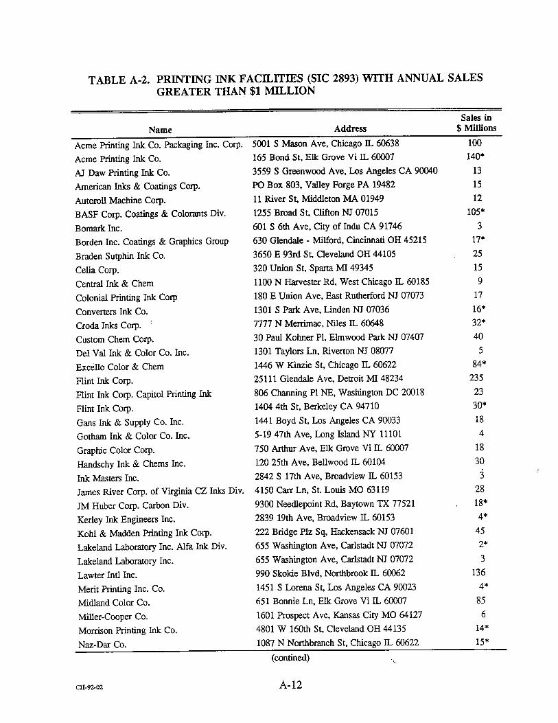
TABLE A-2. PRINTING INK FACILITIES (SIC 2893) WITH ANNUAL SALES GREATER THAN $1 MILLION
Sales in
Name Address $ Millions
Acme Printing Ink Co. Packaging Inc. Corp. Acme Printing Ink Co.
AJ Daw Printing Ink Co.
American Inks & Coatings Corp. Autoroll Machine Corp. BASF Corp. Coatings & Colorants Div.
Bomark Inc.
Borden Inc. Coatings & Graphics Group Braden Sutphin Ink Co.
Celia Corp. Central Ink & Chem
Colonial Printing Ink Corp Converters Ink Co.
Croda Inks Corp. Custom Chem Corp. Del Val Ink & Color Co. Inc.
Excello Color & Chem
Flint Ink Corp. Flint Ink Corp. Capitol Printing Ink
Flint Ink Corp. Gans Ink & Supply Co. Inc.
Gotham Ink & Color Co. Inc.
Graphic Color Corp. Handschy Ink & Chems Inc.
Ink Masters Inc.
James River Corp. of Virginia CZ Inks Div.
JM Huber Corp. Carbon Div.
Kerley Ink Engineers Inc.
Kohl & Madden Printing Ink Corp. Lakeland Laboratory Inc. Alfa Ink Div.
Lakeland Laboratory Inc.
Lawter Intl Inc.
Merit Printing Inc. Co.
Midland Color Co.
Miller-Cooper Co.
Morrison Printing Ink Co.
Naz-Dar Co.
5001 S Mason Ave, Chicago IL 60638 100
165 Bond St, Elk Grove Vi IL 60007 140"
3559 S Greenwood Ave, Los Angeles CA 90040 13
PO Box 803, Valley Forge PA 19482 15
11 River St, Middleton MA 01949 12
1255 Broad SL Clifton NJ 07015 105"
601 S 6th Ave, City of Indu CA 91746 3
630 Glendale Milford, Cincinnati OH 45215 17"
3650 E 93rd St, Cleveland OH 44105 25
320 Union St, Sparta MI 49345 15
1100 N Harvester Rd, West Chicago IL 60185 9
180 E Union Ave, East Rutherford NJ 07073 17
1301 S Park Ave, Linden NJ 07036 16"
7777 N Merrimac, Niles IL 60648 32*
30 Paul Kohner PI, Elmwood Park NI 07407 40
1301 Taylors Ln, Riverton NI 08077 5
1446 W Kinzie St, Chicago IL 60622 84*
25111 Glendale Ave, Detroit MI 48234 235
806 Channing PINE, Washington DC 20018 23
1404 4th St, Berkeley CA 94710 30*
1441 Boyd St, Los Angeles CA 90033 18
5-19 47th Ave, Long Island NY 11101 4
750 Arthur Ave, Elk Grove Vi IL 60007 18
120 25th Ave, Bellwood IL 60104 30
2842 S 17th Ave, Broadview IL 60153 • 4150 Carr Ln, St. Louis MO 63119 28
9300 Needlepoint Rd, Baytown TX 77521 18"
2839 19th Ave, Broadview ]I, 60153 4*
222 Bridge Plz Sq, I-Iackensack NJ 07601 45
655 Washington Ave, Carlstadt NI 07072 2*
655 Washington Ave, Carlstadt NJ 07072 3
990 Skolde Blvd, Northbrook IL 60062 136
1451 S Lorena St, Los Angeles CA 90023 4*
651 Bonnie Ln, Elk Grove Vi II. 60007 85
1601 Prospect Ave, Kansas City MO 64127 6
4801 W 160th St, Cleveland OH 44135 14"
1087 N Northbranch St, Chicago IL 60622 15"
(contined) .•
ca-•oz A-12

TABLE A-2. PRINTING INK FACILITIES (SIC 2893) WITH ANNUAL SALES GREATER THAN $1 MILLION (continued)
Sales in
Name Address $ Millions
Nor-Cot• Intl Inc.
North American Printing Ink
Northern Printing Ink Corp. Polypore Inc.
Polytex Color & Chem
PPG Indus Inc. PPG Ink Products Co.
Rexart Chem Corp. Ron Ink Co. Inc.
Sicpa Indus of America Inc.
Sinclair & Valentine LP
Sun Chem Corp. Sun Chem Corp. Gen. Printing Ink Div.
Superior Printing Ink Co. Inc.
United States Printing Ink Corp. Leber Ink Div.
United States Printing Ink Corp. Van Son Holland Corp. of America
Vivitone Inc.
Walter W Lawrence
PO Box 668, Crawfordsville IN 47933 5
1524 David Rd, Elgin IL 60123 14
8360 10th Ave N, Minneapolis MN 55427 8
4601 S 3rd Ave, Tucson AZ 85714 10
820 E 140th St, Bronx NY 10454 3
1835 Airport Exchange Blvd, Covington KY 41018 15
1183 Westside Ave, Jersey City NJ 07306 6*
61 Halstead St, Rochester NY 14610 7
8000 Research Way, Springfield VA 22153 25
2520 Pilot Knob Rd, St. Paul MN 55120 186
PO Box 1302, Fort Lee NI 07024 1,100
135 W Lake St, Northlake IL 60164 410"
70 Bethune St, New Yod• NY 10014 50
PO Box 88700, Seattle WA 98138 6
343 Murray Hill Pkwy, East Rutherford NJ 07073 65
92 Union St, Mineola NY 11501 42
110 E 27th St, Paterson NI 07514 8
9715 Alpaca St, Soulh E1 Mon CA 91733 1
Wikoff Color Corp.
*Indicates an estimated financial figure. Source: Reference 5, Chapter 2.
PO Box W, Fort Mill SC 29715 45*
cu-9-z-oz A-13

APPENDIX B
PERMIT REQULREMENTS FROM SEVERAL STATES
c•-9•-o2 B- 1


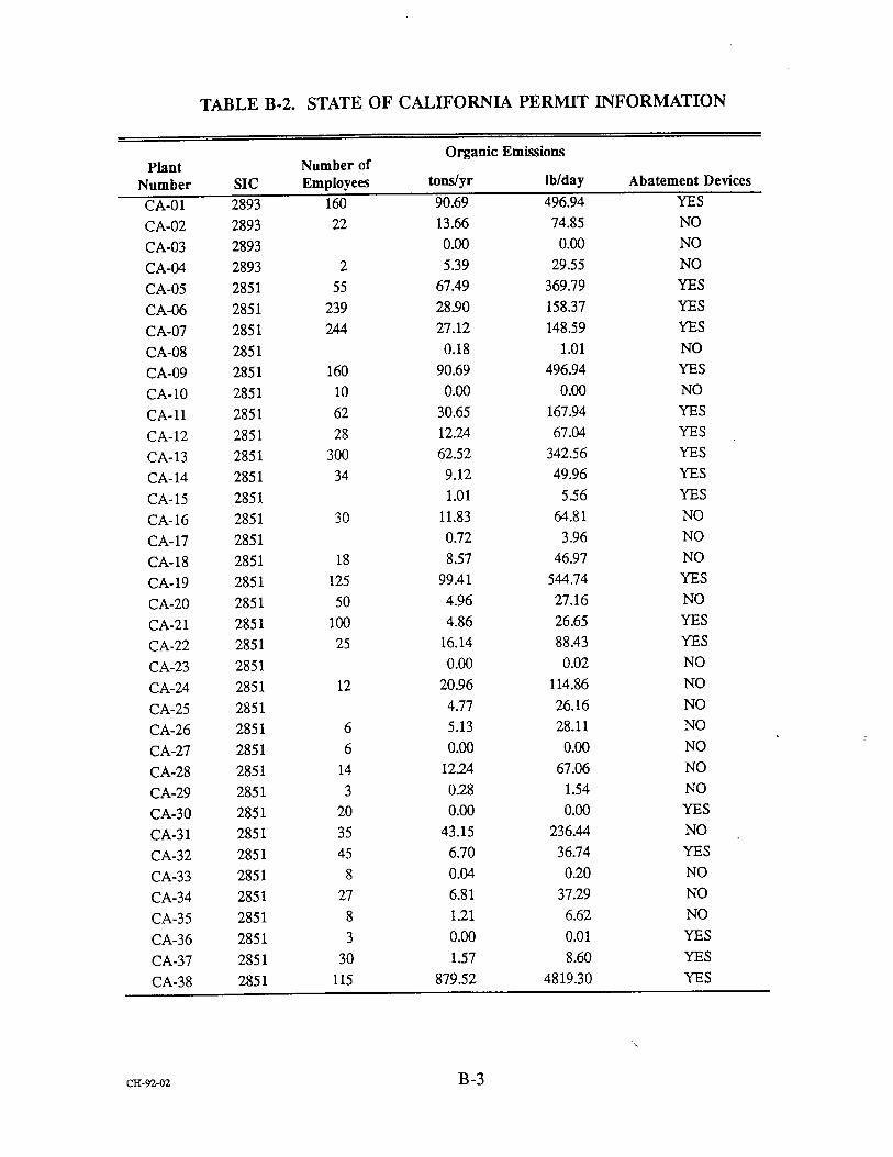
TABLE B-2. STATE OF CALIFORNIA PERMIT INFORMATION
plant Number
Organic Emissions Number of
SIC Employees tons/yr lb/day Abatement Devices
CA-01 2893 160 90.69 496.94 YES
CA-02 2893 22 13.66 74.85 NO
CA-03 2893 0.00 0.00 NO
CA-04 2893 2 5.39 29.55 NO
CA-05 2851 55 67.49 369.79 YES
CA-06 2851 239 28.90 158.37 YES
CA-07 2851 244 27.12 148.59 YES
CA-08 2851 0.18 1.01 NO
CA-09 2851 160 90.69 496.94 YES
CA-10 2851 10 0.00 0.130 NO
CA- 11 2851 62 30.65 167.94 YES
CA- 12 2851 28 12.24 67.04 YES
CA- 13 2851 300 62.52 342.56 YES
CA- 14 2851 34 9.12 49.96 YES
CA-15 2851 1.01 5.56 YES
CA-16 2851 30 11.83 64.81 NO
CA- 17 2851 0.72 3.96 NO
CA-18 2851 18 8.57 46.97 NO
CA-19 2851 125 99.41 544.74 YES
CA-20 2851 50 4.96 27.16 NO
CA-21 2851 100 4.86 26.65 YES
CA-22 2851 25 16.14 88.43 YES
CA-23 2851 0.00 0.02 NO
CA-24 2851 12 20.96 114.86 NO
CA-25 2851 4.77 26.16 NO
CA-26 2851 6 5.13 28.11 NO
CA-27 2851 6 0.00 0.00 NO
CA-28 2851 14 12.24 67.06 NO
CA-29 2851 3 0.28 1.54 NO
CA-30 2851 20 0.00 0.00 YES
CA-31 2851 35 43.15 236.44 NO
CA-32 2851 45 6.70 36.74 YES
CA-33 2851 8 0.04 0.20 NO
CA-34 2851 27 6.81 37.29 NO
CA-35 2851 8 1.21 6.62 NO
CA-36 2851 3 0.00 0.01 YES
CA-37 2851 30 1.57 8.60 YES
CA-38 2851 115 879.52 4819.30 YES
c•-9"z-o2 B-3

TABLE B-3. STATE OF ILLINOIS PERMIT INFORMATION
Plant Number
Organic Emissions Number of
SIC Employees tons/yr Ib/day Abatement Devices
IL-01 2851 6.1620
IL-02 2851 8.9677
IL-03 2851 82.1184
IL-04 2893 14.2071
IL-05 2893 8.1484
IL-06 2893 0.0000
1L-O7 2851 27.9200
IL-08 2893 0.00130
IL-09 2893 0.0000
IL-10 2893 0.0000
]J..-ll 285I 39.8964
IL-12 IL-13 1]_,-14
IL-15 1L-16
2851 3.9000
2851 0.0000
2851 0.0000
2851 64.4000
2851 56.8817
IL-17 2893 0.0000
1L-18 2893 24.9061
IL-19 2851 180.6560
]L-20 2893 1.9520
IL-21 2851 0.0000
1L-22 2893 0.0008
IL-23 2851 7.7103
]L-24 2851 0.0000
1L-25 2851 7.9592
1L-26 2851 1.3632
IL-27 2851 14.1180
IL-28 2851 33.6365
VENTURI SCRUBBER KNOCK OUT TANKS CONDENSOR CATALYTIC AFTERBURNER
CARTRIDGE FILTER CONDENSOR SCRUBBER
CYCLONE
CONDENSOR & SCRUBBER CONDENSORS (PRIMARY & SECONDARY) CYCLONE
CONDENSORS SCRUBBERS CHILLER
CONDENSORS CONDENSORS
SCRUBBERS CYCLONE & BAGHOUSE KNOCKOUT TANKS
VAPOR RECOVERY SYSTEM
CARBON ADSORBERS
(continued)
ca-gz-o'z B-4


TABLE B-3. STATE OF ILLINOIS PERMIT INFORMATION (continued)
Plant Number
Organic Emissions Number of
SIC Employees tons/yr Ib/day Abatement Devices
IL -29
IL-30
2893 280.9783
2851 45.2446
1L-31 2893 0.0000
1L-32 2893 0.01300
IL-33 2851 49.4•00
IL:34 2851 15.4713
IL-35 2851 0.0000
IL-36 2851 11.3100
IL-37 IL-38 IL-39 IL-40 IL-41
IL-42 IL-43
IL-44
IL-45
IL-46
IL-47
IL-48
2851 6.2400
2851 12.2460
2893: 13.3120
2851 3.9610
2851 0.00130
2851 43.8604
2893 17.3750
2851 15.6600
2851 0.0000
2851 18.9280
2851 34.9440
2851 3.5569
IL•9 2851 94.1300
IL-50 2851 9.8000
IL-51 2893 17.4985
IL-52 2851 9.0892
IL-53 2851 0.0000
IL-54 2851 0.0000
1L-55 2851 2.6208
IL-56 2851 17.2680
FUME SCRUBBER CONDENSOR/ELIMINATOR PLATE SCRUBBER CONDENSORS SCRUBBERS
CONDENSORS SCRUBBERS CONDENSORS SEPARATORS
CHARCOAL ADSORBER CHARCOAL FILTER
ROTOCLONE SCRUBBER
ROTOCLONE AFTER BURNER
RECYCLING STILL
VENTURI EDUCTOR CARBON ADSORBERS
CONDENSORS SCRUBBER CONDENSORS VAC ,1.•¢I PU1V[PS SCRUBBERS KNOCKOUT TANKS CATALYTIC AFTERBURNER CONDENSORS SCRUBBERS
(continued)
ca-9z-o• B-5

TABLE B-3. STATE OF ILLINOIS PERMIT INFORMATION (continued)
Plant Number
Organic Emissions Number of
SIC Employees tons/yr lb/day Abatement Devices
1L-57
[L-58 1I,-59
2851 143.2435 SCRUBBERS CONDENSOR SOLN-ABSORBER
2893 86.8543 CONDENSORS
2851 200.5087 CONDENSORS SCRUBBERS
IL-60 2851 1L-61 2851 8.3956
1L-62 2851 83.5848
IL-63 2851 30.2640
IL-64 2851 28.2880
IL--65
IL -66
IL-67
2851 37.5000
2851 217.1960
2851 1.9207
SETI'LING CHAMBERS CENTRWUGAL COLLECTOR
SCRUBBERS CONDENSORS VAPOR RECOVERY
SPEED REDUCTION EQUIPMENT
c•-9•-oz B-6

00000000000000000000
......................... •
B-7

B-8

0 0 z 0 O z
-1 .1 Z ,-1 ..1 Z
Z Z Z Z
B-9

oo•o•-oooooo•oooooo•
B-IO
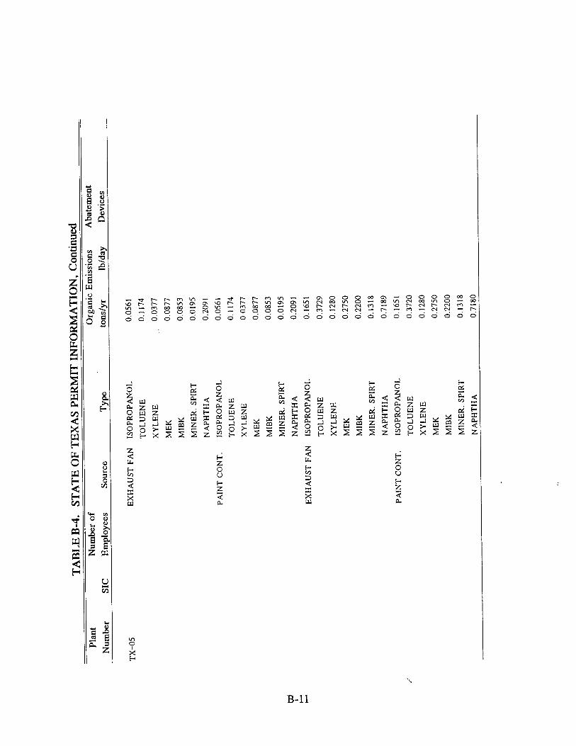
Z
• 0 [" 0
B-11

M •• • Z Z M ZZZZ • •
z o• • • •
< O000• • <
0
B-12

0 • 0 •
0•0•0•0••
000000000000
Z •Z •
oo oo•• z z•XX•z•
Z Z
z
B-13

0
B-14
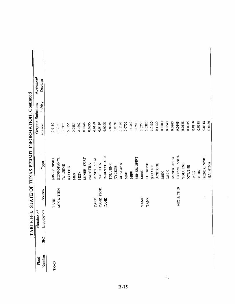
Z•Z Z•Z Z•
B-15

0•0•0•0000000000000 •
•" Z Z Z Z
zz× x_ _x x
o
B-16

B-17
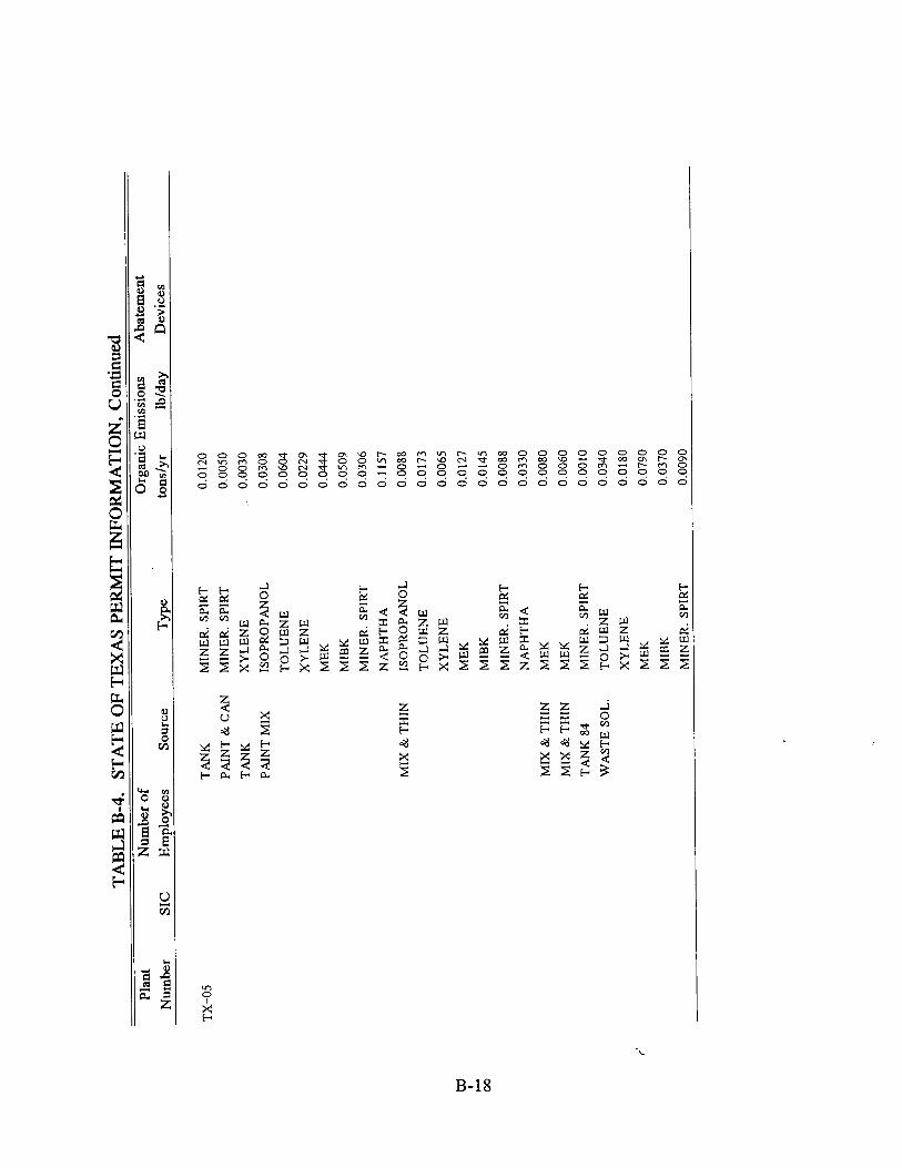
Z
o
B-18
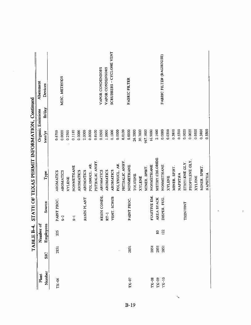
•0•000•000•00000•0•00• •0•000000•000••00•000•
o z • 0
• z z • • •<m z • •Tz z 5•
B-19

B-20

Z
ooooo<<<oo oo<•
Z Z Z Z Z • • • Z Z •
Z Z m Z Z m Z Z Z m • Z < Z
B-21
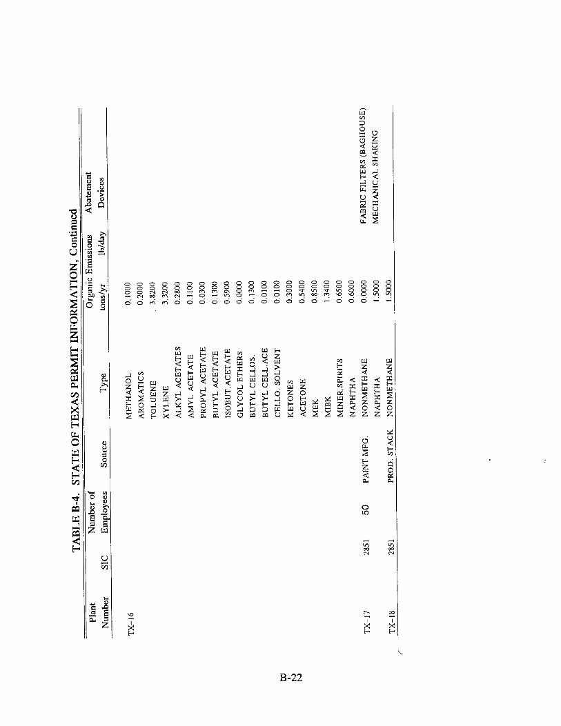
d
B-22

B-23

• Z •° •
z•Z •
o
i °
z o
06 o 66 zzzzT•
Cq •D o'• Cq
O0
d
B-24

APPENDIX C
TRIP REPORTS
c•-•oz C-1


ALLIANCE Technologies Corporation
Date:
Subject:
From:
6 January 1992
Site Visit--ICI Specialty Inks Ink Manufacturing EPA Contract 68-D0-0121; Work Assignment 1-29 Alliance Reference No. 1638029
Beth W. McMinn Alliance Technologies Corporation
Joseph Steigerwald OAQPS/ESD/CTC (MD- 13) U.S. Environmental Protection Agency Research Triangle Park, NC 27711
I. Purpose
The purpose of the visit was to gather information on the ink manufacturing process including information necessary to characterize the process parameters, emissions, control
techniques, and control costs.
II. Place and Date
ICI Specialty Inks 120 Regent Drive Winston-Salem, NC (919) 760-1011
December 18, 1991
27103
III. Attendees
ICI Specialty Inks
Randy Besaw, Plant Superintendent Templeton A. Elliott, Jr., Vice President/Director Safety, Health,
Affairs .,•
& Environmental
100 Eurooa Drive. Suite 150, Chapel Hill, North Carolina 27514 919-968-9900

Tony Martin, Branch Manager Stephen W. Paine, Environmental Engineer
U.S. Environmental Protection Agency (EPA)
Joseph Steigerwald, CTC
Alliance Technologies Corporation (Alliance)
Beth W. McMinn
IV. Discussion
A meeting was held with the personnel from ICI Specialty Inks to discuss the ink
manufacturing process. The discussion focused on market profile, manufacturing supplies, manufacturing process parameters, volatile organic compound (VOC) control experience, and
emission characterization. This discussion was followed by a tour of the production facility in
Winston-Salem, North Carolina, and then by a short closing meeting.
A. ICI Specialty Inks Market Profile
The ICI Specialty Inks facility in Winston-Salem manufactures flexographic and
rotogravure inks for the packaging industry. Many of their inks are used in the printing of
packages for food and snack food products such as Frito Lay, Lance, Hershey, and Mars. ICI
Specialty Inks also produces ink used on the packaging of R.J. Reynolds cigarettes and textile soft
goods packaging such as that used to package pantyhose. The facility places a heavy emphasis on inks for lamination (i.e., ink printed between two layers of film). Approximately 99 percent of the inks manufactured by this location of ICI Specialty Inks are solvent based, while the
remaining one percent is water based. This location of ICI Specialty Inks produces colored, clear,
and white inks. All of their water based inks are flexographic white inks and top lacquers. In
the flexible packaging industry, white inks are high-volume, low profit margin products. They are, consequently, the first type of ink to be converted from solvent based ink because the high volume usage by printers results in the largest reduction on VOC emissions by the printers for
switching a single ink.
Very few of the ICI Specialty Inks printed products come in direct contact with food, therefore, approval from the Food and Drug Administration (FDA) is not a major concern. Food
packagers are, however, sensitive about the inks used in packaging and restrict ink manufacturers
from using heavy metal pigments (i.e., lead, hexavalent chromium, cadmium, and mercury).
The printing/packaging operations that the Winston-Salem ink facility services are located
within a 300 to 400 mile radius. Some of these packaging facilities supply products to a regional area while others service the nation. ICI Specialty Inks takes pride in the quality of its final
product and its "Just In Time" manufacturing policy. In many cases customers like the Charlotte,
CH-92-02 2

North Carolina based Venture Packaging and Package Products will receive same day shipment of ink orders.
The Regent Drive ICI Specialty Ink facility was known as Converters Inks until January 1, 1992. Throughout its history, the former Converters Ink has manufactured solvent based
flexographic and rotogravure inks for the packaging industry. Carl Bear founded the Converters
Ink Company in the 1950's. During the next thirty years, Converters Ink expanded to a total of
12 manufacturing plants, of which nine are located in the United States and three in Canada. In
1971, Beatrice Foods purchased the Converters Ink facRities. The plants were purchased a second
time in late 1984 by ICI Americas, Inc. (ICI). Shortly after the 1984 buyout, ICI constructed the
current Converters Ink facility. Production in the new !2,000 square feet manufacturing facility began in early 1985. Eventually, a 5,000 to 6,000 square feet addition was added. In 1988, ICI
bought five Thiele-Engdahl ink manufacturing plants. The Winston-Salem based Thiele-Engdahl plant concentrates its production efforts in gravure inks used in box and cardboard packaging. Converters Ink and Thiele-Engdahl merged in early 1992 and are now called ICI Specialty Inks.
B. Manufacturin• Supplies
ICI Specialty Inks uses more than 200 raw materials in their manufacturing processes. In
addition to the solvents described in Attachment 1, ICI Specialty Inks also purchases and uses a
variety of resins, pigments, and additives. Corporate headquarters regularly determines product ink VOC content based on raw material safety data sheets and finished good calculations. Some
finished goods are tested for flashpoint determination.
C. Manufacturing Process Parameters
The ink manufacturing process at the Winston-Salem facility is basically a batch process materials handling operation. Products are formed by mixing and blending rather than by reacting materials chemically. No heating of materials is necessary during the processing. A process description and simplified flow diagram are found in Attachment 2. The main manufacturing operations are completed in the following order:
premix pigment grinding/milling product blending product filtering product filling/packaging
The first step in the manufacturing process is material premix. This is the production of
an intermediate product referred to as the base. The base or premix is made by combining vehicles (e.g., solvents, alcohols, resins, and/or water) with pigments and any other necessary additives. The materials are mixed in portable containers to form a viscous material which acts
as a concentrate. At this stage, the particles in the concentrate are rather large (250 Iam) and not
consistently mixed. With further processing, the concentrate may become any one of a variety of specific end products.
-,
CH-92-02 3

The grinding or milling stage serves to further disperse the pigment throughout the base
by pumping it through dispersion equipment. Once the customer-requested grind specifications are met, the resulting base is transferred to the product blending tanks.
Final product specifications are achieved in the blending or product finishing step. The
base from the dispersion operation is mixed with other intermediates and raw materials to produce a finished ink. Blending may occur in the same or in a different tank used for premix.
Once the ink has been blended, it is filtered through various filter media to enhance the
quality and uniformity of the product. Filtering also acts to screen out impurities.
After the ink has been filtered, it is pumped or emptied into shipping containers. Whites
are normally shipped in 400 gallon tote bins while most other products are shipped in 55 gallon drums.
The ICI Specialty Inks facility currently manufacturers over 200 blended products. Formulas change daily, so ICI Specialty Inks keeps a computerized database of several thousand
active product formulations. Because of the wide variety of products and because 65 to 70
percent of business is same day shipments, ICI Specialty Inks does not dedicate manufacturing equipment to specific products. Some equipment is dedicated to certain colors (e.g., whites and
clears) while other equipment is dedicated to ink type (i.e., water or solvent) products.
ICI Specialty Inks uses a variety of equipment during the premix and blending stages. The
facility has many mixers, which are used depending in part on batch size. Drum-sized batches
made in the drum itself may be blended with a portable mixer called a Lightning Mixer. Other
materials made in portable mix tanks may be blended using larger, permanent high-speed or
variable-speed mixers. In some cases, an ink will be premixed with one mixer, moved to a
dispersion mill for grinding and milling, and then transferred back to the same premix mixer for
blending operations.
ICI Specialty Inks operates several types of dispersion mills including three ball mills, a
sand mill, horizontal small media mills, and mix tanks. ICI Specialty Inks makes solvent b•sed
inks in the ball mills. Two ball mills are dedicated to the manufacture of black and blue inks
while the other mill is used for colored ink production. Ball mills are rotating cylinders, mounted
horizontally, and filled with grinding media. Because these mills are used to make solvent based
inks, they contain steel ball media used to disperse pigment. These mills generate heat during the
grinding process, so they are jacketed and water cooled. Production personnel manually load raw
materials (i.e., premix liquids, powders/pigments, and additives) into the mills from a catwalk
through a top chute. Solvents are either pumped from drums or from bulk storage tanks through a manifold system into the ball mills. Other materials are added directly from bags or drums into
the mill. In some cases (e.g., material adjustment), material is dispensed with buckets. Material
loading is done during the day and the grinding process, which is noisy, is done during the night and is controlled by a timer. The following day, the product is inspected, properly adjusted, and
then unloaded by gravity feed, filtered, and packaged into containers for shipment or for further
use as intermediates in the facility. Ball mills approach a closed system as they are open only during addition of raw material and product filling operations.
.,•
CHo92-02 4

Horizontal mills are similar to ball mills except that they are much smaller and operate continuously rather than by batch although they are fed by batches. Rather than using steel balls, ICI Specialty Inks's horizontal shot mills use tiny various grinding media. Rather than having a rotating hollow cylinder tumble media as in the case of the ball mills, the shot mills feature a
stationary hollow cylinder with a rotating internal shaft which has pegs affixed to vigorously agitate the media. The Winston-Salem facility manufactures water based inks in one mill and
solvent based inks in the other. Some of the products manufactured in the water based shot mill
are shipped to customers while other products are sent to sister ICI Specialty Inks facilities. ICI
recently chose the Winston-Salem facility to begin producing waterborne base concentrates for
use in other ICI owned ink plants.
ICI Specialty Inks also operates a sand mill to manufacture solvent based inks. This mill
uses fine-grained Ottawa sand to accomplish pigment dispersion. Material enters through the
bottom of the mill and is forced up through the sand to an open-top filtering screen. The screen
often clogs as the material filters out of the mill and into a receiving hopper. Because the mill
must be scraped down regularly, enclosing the filter would create processing difficulties.
In addition to the mills, ICI Specialty Inks operates a number of fixed mix tanks with
agitators which are used for mixing, milling, and blending both water and solvent based white
inks and varnishes-. Two of these mix tanks are dedicated to the production of white inks.
Material is added through the top, agitated, and gravity fed out the bottom. The top openings on
the mix tanks are covered with permanent aluminum lids which are opened only during the
addition of product components. The lids contain a center opening through which the agitator shaft extends. The lids also have a small hinged opening to allow for gradual product additions.
The ICI Specialty Inks facility operates 9 hours per day, 5 days per week, 52 weeks per
year. A typical batch can take 3 to 20 hours to complete. More time is required to manufacture
colored rotogravure inks than other inks. Viscous or dry materials take longer to grind and
achieve proper dispersion than less viscous materials. Batch sizes range from five gallons to
1,100 gallons.
Equipment is cleaned manually on an as-needed basis. Cleaning frequency depend• on
the number and size of batches processed, the size of the equipment to be cleaned, and the color
and type of ink manufactured. After a mill or tank has been emptied, solvent is added to the
vessel to capture remaining product residue. The wash solvent is drained from the tank and
recycled into the next product batch of that particular product whenever possible. Disperser blades are cleaned with ethanol and n-propyl-acetate, which is used repeatedly until it is pigment saturated. Once becoming unusable as a cleaning solvent, the wash material is sent off-site as
hazardous waste. Mills are cleaned by replacing the residual heel of the exiting product with an
equivalent amount of solvent which is compatible with both the preceding and the ensuing batches. Some base raw materials and solvents are handled via a manifold system using dedicated
process lines. Therefore, cleaning of these lines is limited. ICI Specialty Inks is unable to
schedule consecutive production batches of similar products to reduce equipment cleaning frequency because they operate on a same day shipment schedule.
CH-92-02 5
D. Volatile Organic Compound Control Experience
The ICI Specialty Inks facility has no add-on control devices for the capture and
destruction of VOCs. Volatile organic compounds emitted from the manufacture of solvent based
inks are controlled through equipment modifications such as tank covers.
Drop hoses are used around all mixing and some milling equipment to capture and remove VOC material from the work area. Captured emissions are routed through the hoses to a central
ventilation system and eventually to the outside. The facility also uses fans operating at 6000 cfm
to achieve approximately six air exchanges per hour in the manufacturing area.
ICI Specialty Inks operates under permit no. 00758-001-P in accordance with Section 3-
166 of the Forsyth County Air Quality Technical Code, which restricts the ink facility from
emitting more than 40 pounds of photochemically reactive compounds in a 24-hour day. This
permit also requires that all ink manufacturing vessels be covered at all times while mixing, storing, transferring, and handling.
Because the facility's VOC control emphasis has been on lids, ICI Specialty Inks has tried
several different types. Initially, the facility used homemade plywood covers on both drums and
mix tanks. The wooden covers were difficult to clean, so ICI Specialty Inks stapled plastic to the
bottom. The plastic frequently came loose and would be pulled into the mix tank, tangling with
the mixing blade. ICI Specialty Inks then tried using Kraft paper in hopes that the lighter weight would .prevent the staples from pulling away from the wood. The paper did remain attached to
the wood, but it became saturated with ink.
ICI Specialty Inks then moved to aluminum lids. Flat lids, which are made by a sheet
metal contractor, cost $20 to $25 dollars for drums and $300 dollars for a 250 gallon mix tank
(see Attachment 3). The flat lids have worked relatively well, but they do have some inherent
flaws. The lids do not form a complete seal with the mix tank and the hinged door product addition chute does not always remain closed. For these reasons, ICI Specialty Inks moved to
conical lids which are a better engineering design. The conical aluminum lids cost $1500 dollars.
The added weight and bulky shape led to worker ergonomic difficulties. Because these lids v•ere difficult to handle, they were damaged more often than the flat lids. The increased replacement and upkeep costs prompted ICI Specialty Inks to return to flat lids.
ICI Specialty Inks may now change to stainless steel lids because of the recent information
released by the Bureau of Mines in England dealing with the reactions of aluminum and steel.
Many of the facility's portable mix tanks and permanent blend vessels are carbon steel. In
addition, almost all of the 55 gallon drums are steel.
Attachment 4 contains a description of a cover efficiency test conducted at one of the ICI
Specialty Inks's sister facilities. Although the test proved sensitive to weigh scale calibration (one of two tests done in 1991 proved unrepresentative), it does provide a lid testing methodology and
initial results comparing an uncovered mix tank and a tank covered with a sealing conical lid.
CH-92-02 6
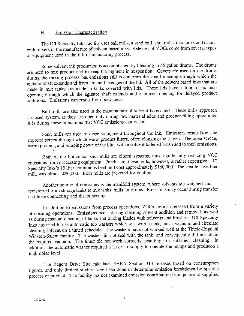
E. Emission Characterization
The ICI Specialty Inks facility uses ball mills, a sand mill, shot mills, mix tanks and drums
with mixers in the manufacture of solvent based inks. Releases of VOCs come from several types of equipment used in the ink manufacturing process.
Some solvent ink production is accomplished by blending in 55 gallon drums. The drums
are used to mix product and to keep the pigment in suspension. Covers are used on the drums
during the mixing process but emissions still occur from the small opening through which the
agitator shaft extends and from around the edges of the rid. All of the solvent based inks that are
made in mix tanks are made in tanks covered with lids. These lids have a four to six inch
opening through which the agitator shaft extends and a hinged opening for delayed product additions. Emissions can result from both areas.
Ball mills are also used in the manufacture of solvent based inks. These mills approach a closed system, as they are open only during raw material adds and product filling operations. It is during these operations that VOC emissions can occur.
Sand mills are used to disperse pigment throughout the ink. Emissions result from the
exposed screen through which warm product filters, often clogging the screen. The open screen,
warm product, and scraping down of the filter with a solvent-ladened brush add to total emissions.
Both of the horizontal shot mills are closed systems, thus significantly reducing VOC
emissions from processing equipment. Purchasing these mills, however, is rather expensive. ICI
Specialty Inks's 15 liter continuous feed mill cost approximately $160,000. The smaller five liter
mill, was almost $80,000. Both mills are jacketed for cooling.
Another source of emissions is the manifold system, where solvents are weighed and
transferred from storage tanks to mix tanks, mills, or drums. Emissions may occur during transfer
and hose connecting and disconnecting.
In addition to emissions from process operations, VOCs are also released from a variety
of cleaning operations. Emissions occur during cleaning solvent addition and removal, as well
as during manual cleaning of tanks and mixing blades with solvents and brushes. ICI Specialty Inks has tried to use automatic tub washers which seal with a tank, pull a vacuum, and circulate
cleaning solvent on a timed schedule. The washers have not worked well at the Thiele-Engdahl Winston-Salem facility. The washer did not seal with the tank, and consequently did not attain
the required vacuum. The timer did not work correctly, resulting in insufficient cleaning. In
addition, the automatic washer required a large air supply to operate the pumps and produced a
high noise level.
The Regent Drive Site calculates SARA Section 313 releases based on consumption figures, and only limited studies have been done to determine emission breakdown by specific process or product. The facility has not examined emission contribution from janitorial supplies.
CH-92-02 7

Attachment 1
TOTAL 1991 VOC PURCHASES (IN POUNDS)
TOLUOL
ETHANOL
IS OPROPYL-ACETATE
LACTOL SPIRITS
BUTYL CARBITOL
ETHYL ACETATE
IS OPROPYL-ALCOHOL
N PROPYL-ALCOHOL
VM&P NAPTHA
DOWANOL PM
MEK
HEPTANE
N PROPYL-ACETATE
TOTAL POUNDS IN INTERMED. VARNISHES
TOTAL PURCHASES OF VOC'S/1991
53433
711650
112530
669
11004
17272
1360O
197950
8909
5550
366
142175
281575
444175
2000858
CH-92-02 8

Attachment 2 INK MA•NLrFACTIJR_h-NG OVERV-I•W
Raw Mate.'JN Receiving./Storn•.•ee. Liquid materials are re•.ve• in drums or in bulk:
solvents used in large quantities are stored in above or be!ow ground storage trunks and/or
in portable "tote" tanks. Dry materials are received and stored in bags or drums.
Dispersing. This is the production of an intermediate product, usually referred to as a
base. A 'premix' is performed in which vehicles (i.e., solvent, alcohol and/or water) are
added to a mixing vesse!, along with any dry pigments and other chemicals. The batch
is mechanically mixed with a special slotted blade. Typically the mixing vessel has a
cover with an orifice which the mixer shaft goes through, and a smalt hinged opening to
allow delaved addition of certain raw materials, after mixing has already commenced.
The result of the dispersion/mixing operation is a raw concentrate which has the potential to become any of a family of specific end producm (inks), but which requires further
processing so do so.
Grinding/Milling. This is the step of taking a raw base, which still contains fairly large particles (250 /xm) and incompletely mixed pigment, and grinding it. The premix is
pumped through a chamber containing sand, stee! shot or other small spherical media. Mechamcaily driven discs, or a rotor, is used to churn the media and break uD the
pigment agg!omerates. The result is a more homogeneous product with improved gloss and other physical propemes. The ope•tion is a batch one, in which a pre-mixed base
is pum.•d •n.rough the mill and into a receiving vesse!. Using a 4,000 lb. batch as an
example, the :process can take from 3-4 hours up to 20, depending on whether re-
grinding is needed. Mill .types include semi-closed (as in the attached flow diagram) and
closed units. Ball mills are a special .type of c!osed unit which does not. feature
continuous product feed. Instead, raw mate•als are added to a hollow vesse! containing approximamIy 1" diameter spheres; the vessel is c!osed and slowly turns, tumbling the
contents m mix them. The result is usually an intermediate (base) rather than a finished
product.
Blending. Intermediates and any raw materials not n•xting previous processing are
mixed in s.•.zific quantities to produce a finished ink. The blending occurs in the same
vessel, or a vessel similar to that used in the dispersing/premix step.
Filtering. Finished product is strained through cloth or other filters to enhance quality. and uniformity of the product.
Packaging. After filtration, finished product is pumped or emptied into the final shipping container: pails, drums, portable tanks or occasionally tank truck.
Cleaning. Blending vessets, mills, filter screens and other equipment is routinely cleaned with solvent after production of an ink formulation. In a few plants, only one color or
a limited number of colors are produced, eliminating the need for cleaning be•een color
changeovers. With mixers, the vessel will be completely cteaned and emptied; with
mills, typically a residual 'heel' of finished product is replaced by an equivalent quantity of ctean soivent which is compatible with both the preceding and ensuing batches.
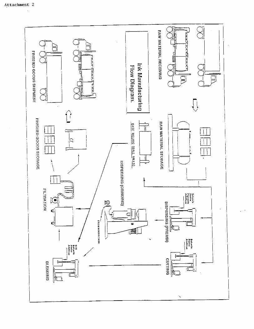
Attachment 2
0 0
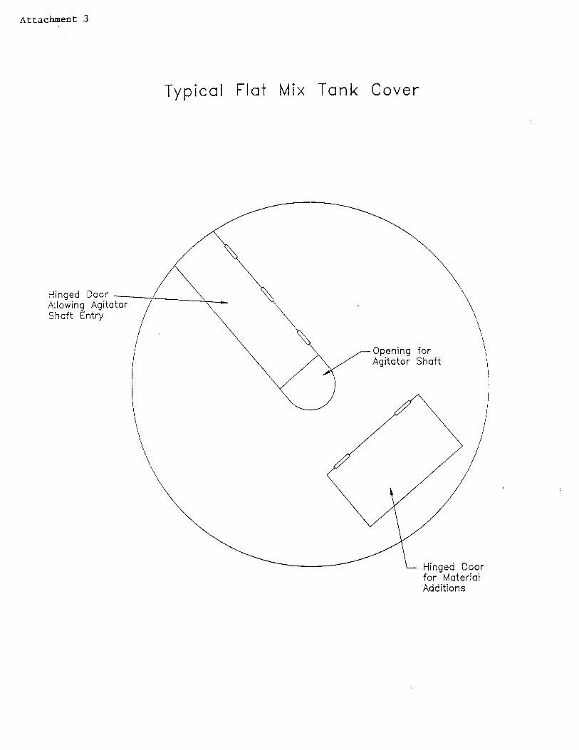
Attachment 3
Typical Flaf Mix Tank Cover
for Material Additions

Attachment 4
September 23, 1991
Engineer Forsyth County Envkonmental Affairs Department 539 N. Spruce Street Winston-Salem, NC 27105
Thiete-Engdahl 7830 Non• Roint Etv•. Suite 101 Winsmn-Saiem Nortlq Carciina 27106-2209
Te!epnone (919) 759-025a Fax (919) 759-0281
Dear M_r. KZrktand:
T'rds is to r•ort to you concerning the results of the emXssion test obse.wed by you at our
FairchJid Road Plant on Seotember !6, 1991. For your information, soread sheets are attached
for both this test and the Au•st i9, 1991 run fwhich proved to be unre'are_sentative due to
scale catibration problems).
The processing sequei•ce, in review, cma be described as foilows:
a) Empty. mix tank weighed
b) Pre-mix ingredients added to rrLLx tar& (to achieve reLpec•ve pmpo•ons in batch), while tank is sti.l.1 on weigh scales:
1) Toluene 2) Liquid and dry ingredients, desi•-ded 'A', 'B', and 'C'
c) Transfer mix tank to work station, start mix
d) Determine weight of additives to be introduced at mixer
1) Weigh pallet of additives #1 and m ,T'•
2) Eand carry bags of additive #1 to mixer, add, and remm empty bags to pa.llet 3) Record weight of pallet after •rget weight of additive #1 achiev• in mix tank
4) Hand carry bags of additive • to mixer, add, and re.nkm empty bags to pallet 5) Sweep up any spiIIage of additives #1 and #2 and renxm to pallet 6) Record weight of pallet including unused bags of product, subtract (d)(I), above
Chicago Cleveland Richmond Winston-Salem
Pa.,1 ot ICI Spe•alt•es A Business Umt of ICI Americas Int.
Chattanooga New York Cincinnati West Monroe Berkeley

Attachment 4
,.Mr. Mike Ki.rktand September 23, 1991 Page 2
Add net weight of any quantity of additive #1 or additive #2 not included on the original pallet, i.e., if it did not have enough of one of these and it was necessary to supplement from a bag not on the original pallet, etc.
e) Complete mix cycte, take sarnples for quality control
f) Record weight of full mixing vessel at scales"
This concludes the process cycle for batch mixing, the operation for which the control equipment effectiveness is being measured. As you observed, an ancillary operation, dram--off of a finished batch, occurs immediately after the mixing. The data associated with this is appended for completeness.
However, it is emphasized that the drum-off dam should not be considered applicable in evalualing the effectiveness of the mixing vessel covers. As you may recall, the sta•mg of the mixing vesset during drum-off required the vessel to be tilted, so that the cover was only partially in place (the material char•_ng hatch was open). More impormntty, the so,vent loss during drum-off came, in large part, from the open drums during the fi11. Also contributing was
the operation and manipulation of the filter bags atmch• to the tap near the bottom of the vessel. Neither the drums nor the •ter bags were able to be affect•t by the mixer cover only the mixing operation was. For this reason, the percent em.issions reduction achieved by this control equipment is evaluated for the process steps during which it is •doing something', (b) through (f), above.
Reviewing the results of the September 16, 1991 test, the total weight of all batch ingredients and of the 10 drum mix vessel was 4789.5 lbs., using the cover. The weight immediate!y after the mix was completed was 4787.5 lbs; after waiting on the scales due to QA/QC approval an•i to a rush order being run, it was 4786.5 lbs. Allowing for two (2) 4 oz. quality control samples that were withdrawn, the net loss during the test was (4789.5 4786.5 + 0.25 + 0.25), or 2.5 lbs.
For the test without a cover, the weight of the mix vessel and of all ingredients was 4,702 lb. The weight after the mix and after a waiting period approximately the same as that following the covered-mixer test was 4679.5 lbs. Allowing for the 0.5 lb. withdrawn for quality control samples, the net loss was (4702 4679.5 + 0.25 + 0.25), or 22.0 lbs.
May be done either before or after QA/QC clearance, but should be consistent for both cover•t and uncovered mixing vessels.

Attachment •
Mike K•kiand September 23, 1991 P•e 3
Based on the above, the control efficiency of the ,7•ixer cover i• 22.0 2.5 x 100%, or 88.6%. 22.0
This i• consistent with previous dam, though we would not have ben surprised by kigher numbers given irnprovement• in the cover de•i•.
We betieve this data indicates compliance with Forsyth County Environmental Affairs Department regulations. Please le'• us know if you have any questions regarding the report. Tnank• for your time and attention.
Sincerely,
Stephen W. Paine Environmental
cc: (with attachment.s)
T. A. Scott Tredaaway Iohn Tanner Steve Sutton Bruce Gammon Hank Greenwood

Attachment 4
Y[LX VESSEL COVER TEST SE•ER 16, 1991
VESSEL WITH COVER
Item Wt. Batch Time Pounds Total
Lb.
Tank 930.5 930.5 9:41 a..m.
Toluene 2753.5 3684.0 10:0"/:•.m.
l_ngredienr A 151.0 3835.5 10:06 a.m.
Ln•tient B 76.5 3912.0 10:ll a.m.
Ingredient C 38.0 3950.0 10:17
(Star• Mix) 10:29 a.m.
P•LI.• incl. • 988.0 additiv•
pall• l¢•s mix 537.5 4-•00.5 £0:}5 •.m.
additive #I
Patlex less mix 148.5 4789.5 I0:4• •.m.
additive if2
Partial bag NIA N/A
supplement
Mix complete; (0.5) 4789.0 11:34 a.m.
Quality control assume) samoic taken
Weight afar 4787.5 11:39 a.m.
4786.5 1:58 p.m.
VESSEL WrI•OUT COVER
Item Wt. Batch Time Pounds Total
Lb.
848.0 848.0 10:54
2756 360•.0 II:19 a.m.
151.0 3755.0 11:25 a.m.
76.0 3831.0 11:29 a.m.
38.0 3869.0 11:3.2 a.m.
11:42 a.m.
991.5
538.5 4312.0 11:41 a.m.
178.5 4-68•.0 11:50 a.m.
20.0 •,702.0 11:52. a.m.
(0.5) 4701.5 12:52 p.m. (assumed)
Weight aRer QA/QC holding Time & wai•
on scales
*'4.688.5 (extra•la•)
4679.5 3:23 p.m.
Net loss with cover 4789.0 Net loss withou• cover 4701.5 4786.5 •U579.5
2.5 "•".0
"•'• '• < 100% 88.6% Control efficiency of covers =_.0 x
!2.0
When one time recording i• made for an a=i•ivy, the time indi• completion.
Vessel not weighed hnmediamly arm" mix due to employee lunch break. Solvent loss betwc•m completion of mixing and
Ia•r weighing of vessel •sumed protmrtionai to mud loss during mixing and waiting times, combined. It in emphasized that a 2 + hour wait for drumming-off h unusual and was caused by Wring to • th.h t•t into a given time slot, then having
a rush order come up from a customer, tying mp the sea/es.
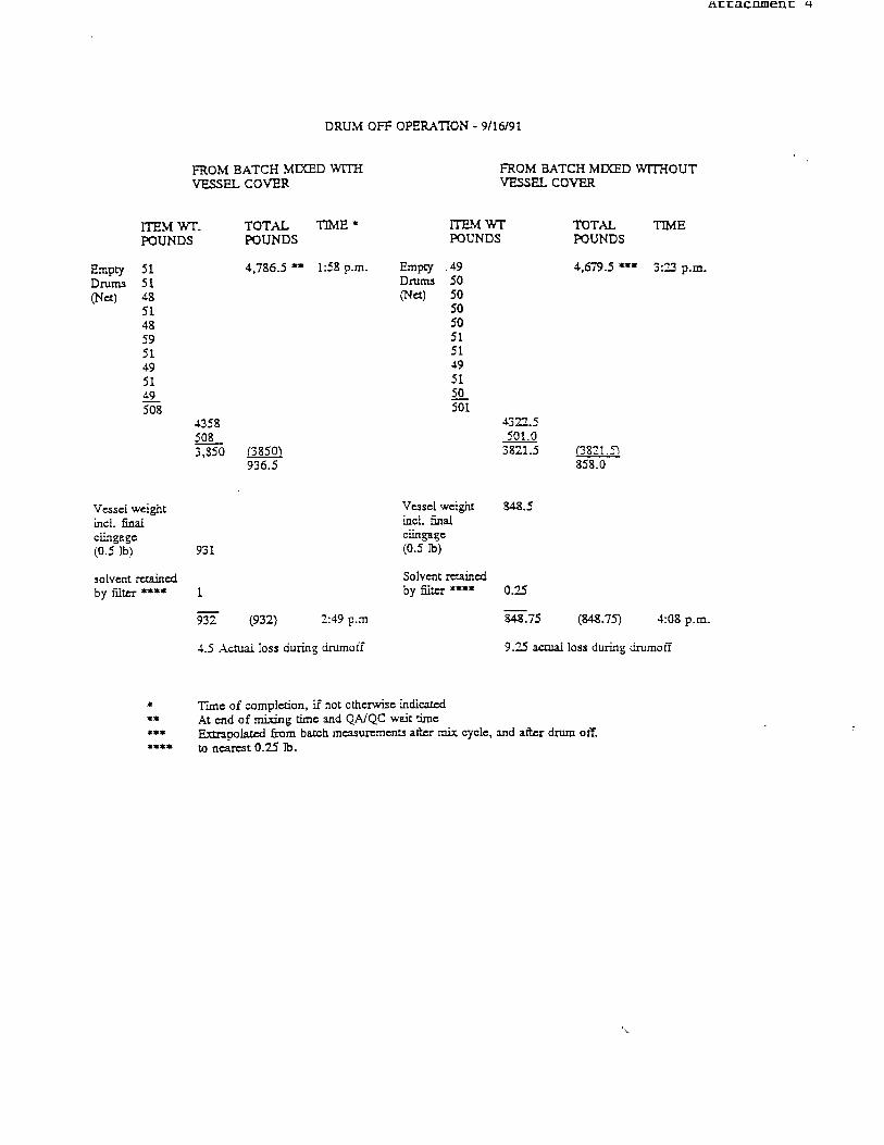
DRUM OFF OPERATION 9/16/91
FROM BATCH MIXED WITH VESSEL COVER
FROM BATCH MIXED WITHOUT VESSEL COVER
ITEM WT. POUNDS
TOTAL TIME POUNDS
Emp•
•8
•8 59
49
4,786.5 i:.<• p.m.
4358 508 3,s5o •
936.5
V•sel weight incl. fin• cingag• (0.5
solvent r=tain•d by fikcr
931
1
932 (932) 2:49 p.m
4.5 Actual loss during drumoff
ITEM WT POUNDS
Empty .49 Drums 50 •et) 50
50 50 51 51 49 51
501
Veaset weight icl. final
(0.5 to)
Solvent r=•ain•d by •.tcr
TOTAL TIME POUNDS
4,679.5 3:0_2 p.m.
4322.5 501.0 3821.5 ('2821
858.0
848.75 (8•8.75) 4:08 p.m.
9.2-5 actual loss during/turnoff
Thn¢ of complexion, if not otherwise indicated At end of mixing tim= and QA/QC wait time Extrapolated from batch measu•ment• a•r mix cycle, and after drum off. to ncar•t 0.25 lb.
ALLIANCE Technologies Corporat,on
Date:
Subject:
From:
6 January 1992
Site Visit--The Perry & Derrick Company Paint Manufacturing EPA Contract 68-D0-0121; Work Assignment 1-29 Alliance Reference No. 1638029
Beth W. McMinn Alliance Technologies Corporation
Joseph Steigerwald OAQPS/ESD/CTC (MD- 13) U.S. Environmental Protection Agency Research Triangle Park, NC 27711
I. -Purpose
The purpose of the visit was to gather information on the paint manufacturing process including information necessary to characterize the process parameters, emissions, control
techniques, and control costs.
II. Place and Date
The Perry & Derrick Company 2510 Highland Avenue Cincinnati, OH 45212 (513) 351-5800
December 13, 1991
III. Attendees
The Perry & Derrick Company (Perry & Derrick)
John J. Jones, Plant Manager Hugh W. Lowrey, Technical Director Gregory R Schott, Production Manager
"00 Europa Drive. Suite 150, Chapel Hill. North Carolina 27514 919-968-9900

U.S. Environmental Protection Agency (EPA)
Joseph Steigerwald, CTC
Alliance Technologies Corporation (Alliance)
Beth W. McMinn Stephen A. Walata
IV. Discussion
A meeting was held with the personnel from Perry & Derrick to discuss the paint manufacturing process. The discussion focused on market profile, manufacturing supplies, manufacturing process parameters, volatile organic compound (VOC) control experience, and
emission characterization. This discussion was followed by a tour of the production facility in
Cincinnati, Ohio, and then by a short closing meeting.
A. Perry & Derrick's Market Profile
The Cincinnati facility produces both water (latex) and solvent (oil) based industrial and
consumer paints. Perry & Derrick's industrial coatings are used in many markets including metal
cans and containers, metal furniture, general metal, machinery and equipment, and electronics.
Perry & Derrick does not sell paints into coil coating, exterior car coating, wood finishing, or
major appliance coating areas. The company's consumer paints are sold over the counter under
manufacturer and private labels to customers for interior and exterior painting needs.
Perry & Derrick began manufacturing resins and solvent based consumer paints in 1913
in Dayton, Kentucky, with sales offices in Cincinnati, Ohio. The family-owned business gradually expanded into the industrial market. In the late 1950's, a fire in the Dayton facility raw material
warehouse caused the company to move paint manufacturing operations to Cincinnati. This move also prompted Perry & Derrick to begin manufacturing latex consumer paints. The resin facility remained in Dayton. As environmental and Occupational Safety and Health Administration
(OSHA) rules became more stringent, Perry & Derrick made the decision to leave the resin
manufacturing business. Since 1987, Perry & Derrick has manufactured only consumer and
industrial paints.
Water based paints currently account for 59 percent of total production with 55 percent being consumer products and 4 percent being industrial products. The remaining 41 percent of
manufacturing is solvent (oil) based; 17 percent of this market is for consumer use while 24
percent is for industrial use. Two years ago the Pen-y & Derrick sales team asked thier industrial
solvent based paint customers to move to water based coatings. Although the customers
demanded, and some still require, solvent based products, Perry & Derrick has concentrated new
product development in the area of waterborne coatings. Some product development still occurs
in the area of solvent based products. The majority of Perry & Derrick's consumer products contain less than one pound per gallon VOC, but some gloss and semi-g.loss latex paints contain
CH-92-02 2

nearly three pounds. Industrial coatings range from water thinned products with almost zero VOC
to conventional lacquer-type coatings (manufactured for unregulated customers) with as much as
six pounds per gallon VOC.
The Perry & Derrick facility produces just under 1,000,000 gallons of paint annually. They also employ a total of 77 people, 48 of whom are production employees.
B. Manufacturing Supplies
Perry & Derrick uses approximately 700 raw materials in their paint manufacturing processes. In addition to the solvents and alcohols described in Attachment 1, Perry & Derrick
also purchases and uses a variety of resins, pigments, and additives. Perry & Derrick regularly calculates VOC content using a finished product rather than a raw material standpoint.
C. Manufacturing Process Parameters
Since Perry & Derrick left the resin production business in 1987, the paint manufacturing process at the Cincinnati based facility has been a batch process materials handling operation. The method of product formation is by mixing and blending rather than by reacting materials
chemically. The four main manufacturing operations are completed in the following order:
preassembly and premix pigment grinding/milling product finishing/blending product filling/packaging
The first step in the manufacturing process is preassembly and premix. In this step, the
liquid raw materials (e.g., resins, solvents, alcohols, and/or water) are mixed in portable containers
to form a honey-like material to which pigments are added. The pigment and liquid mixture form
a viscous material which is then sent to the grinding operations.
The grinding or milling stage serves to further disperse the pigment throughout the paste. Once the customer-requested grind specifications are met, the paint mixture is transferred to the
product finishing tanks. Normally, this step serves to disperse insoluble solid materials. If
insoluble materials are not present, the grinding/milling stage may be omitted as sufficient
blending will have occurred in premix.
Final product specifications are achieved in the blending or product finishing step. Here, the paint mixture from the dispersion operation is tinted, if necessary, and further reduced, or
letdown, with resins, solvents, and alcohols or water in agitated tanks.
Once the paint has been "finished," it can be transferred from the finishing tanks into pails, drums, tote tanks or tank wagons for shipment. The paint is normally filtered during the transfer
step.
CH-92-02 3
Perry & Derrick offers their customers more than 1000 different products. Many of these
products are manufactured for specific customer needs. Paint formulations change as customer
requirements change. New product development and product revisions typically occur several
times per week. One base product may have several different variations which may be
manufactured in a variety of equipment. Because of this, Perry & Derrick is unable to dedicate
manufacturing equipment to specific products. Most of the equipment is, however, dedicated to
paint type (i.e., water/latex or solvent/oil). In several cases, equipment is further reserved for
induswial solvent based paints or consumer latexes.
Perry & Derrick uses high speed dispersers, mixers, Kady mills and ball/pebble mills in
the preassembly and premix stage. The agitation keeps the pigment in suspension and supplies the dispersion equipment with a consistently mixed material. Dispersers and mixers are used with
insoluble powders prior to the milling stage. If the dry materials are soluble, •ransfer to another
type of dispersion equipment is unnecessary. Product milling, Step 2, and premix, Step 1, may
be accomplished in a single process.
Perry & Derrick currently operates four types of dispersion equipment: Kady mills, media
mills, ball/pebble mills, and high speed dispersers. Ball/pebble mills are rotating cylinders, mounted horizontally, and filled with grinding media. The company operates one steel ball mill
which is used to disperse pigment in solvent based paints. The pebble mills, which use flint
pebbles as grinding media, disperse both oil and water based products. Certain paints can be
made in entirety in ball mills and packaged directly into containers. The mills are loaded through
a top chute with raw materials (i.e., premix liquids, powders/pigments, and additives) during the
day and the grinding process is completed during the night. The following day the product is
inspected, properly adjusted, and then unloaded by gravity feed, filtered, and packaged into
containers for shipment. The mills mn at night because of the noise generated during the grinding process. They approach a closed system as they are open only during additions of raw materials
and product filling operations.
The media mill at the Perry & Derrick facility is a sand mill. Rather than using sand, this
vertical mill uses tiny glass, ceramic, or zirconia media to accomplish pigment dispersion. Material enters through the bottom of the mill and is forced up through the media to an open-top filtering screen.
Kady mills are unlike most of the other dispersion mills in that they are jacketed allowing for heating capability. These mills have permanent lids which allow them to be covered during grinding operations. Perry & Derrick uses Kady mills for the production of solvent based
material. The largest of the facility's three Kady mills is used in the manufacture of a high-solids paint.
The Perry & Derrick facility also uses high speed dispersers to grind pigment into paint. These dispersers are adjustable and are used with portable mix tanks. The portable tanks are
covered during the manufacture of solvent based products. Covers are normally made of stainless
steel with openings for the agitator shaft.
CH-92-02 4

The Perry & Derrick facility uses ball/pebble mills, Kady mills, vertical media mills, mix
tanks, and blend vessels in the manufacture of solvent based paints. Releases of VOCs come
from severn types of equipment used in the paint manufacturing process.
Ball/pebble mills are used in the manufacture of solvent based paints. These mills
approach a closed system, as they are open only during additions of raw materials and product filling operations. It is during these operations that VOC emissions can occur.
VOCs may be emitted during solvent based paint blending and milling operations in the
Kady mills. The mixing operations generate friction which causes product temperatures to rise
resulting in the volatilization of organics in the paint formulation. Emissions may also be released
during material additions when the mill covers are open.
Vertical media mills, or sand mills, are used to disperse pigment throughout the paint. Emissions result from the exposed screen, through which warm product filters, possibly clogging the screen. An operator might apply solvent to unclog the screen, adding to total emissions.
Another emission source is portable mix tanks and blend vessels. Portable mix tanks are
used to mix product and to keep the pigment in suspension. They are also used to transfer
material from one manufacturing stage or area to the next. While they are being used for mixing, the tanks are often, but not always, covered. If a cover is used on a mix tank during mixing, it
will have a four to six inch opening through which the agitator shaft extends. In some cases (e.g., water based paint manufacturing), only a splash guard is used to cover the back haft of the mix
tank. When mix tanks are used for temporary storage, they are covered with a solid lid. None
of the lids seal with the mix tank. Blend vessels not equipped with sealing lids are another source
of VOC emissions. Emissions may occur during product addition through the top opening. Because the lids do not form a seal with the tank, gradual emissions during paint processing are
possible.
Emissions are also possible from the scale systems where solvent and resin raw materials
are measured and transferred from storage tanks to mix tanks or other containers. Emissions may
occur during transfer and hose connecting and disconnecting.
In addition to emissions from process operations, VOCs are also released from a variety of cleaning operations. Solvents are used to clean the Kady mills and other equipment used to
manufacture solvent based paints. Emissions occur during cleaning solvent addition and removal.
Perry & Derrick calculates SARA Section 313 releases based on consumption figures, so
no studies have been done to determine emission breakdown by process. The facility has not
examined emission contribution from janitorial supplies.
CH-92-02 6

Some products manufactured by Perry & Derrick are finished in the equipment in which
they completed the dispersion process. Others are transferred to permanent blend vessels for
product adjustment and letdown. In the permanent vessels, material is added through the top, agitated, and gravity fed out the bottom. The top openings on the tanks are covered with
permanent lids, which are opened only during the addition of product components. When the
product is ready to be packaged, it is transferred to the filling department where it is filtered using a Vorto-Siv, a nylon mesh or felt bag, or a cartridge filter.
The Cincinnati based facility operates eight hours per day, 298 days per year. Batch sizes
range from less than one gallon to 1600 gallons, with most of the production volume coming from
batches in the 300 to 1600 gallon range. Process tanks range from a 270 gallon ball mill to a
1600 gallon mix tank.
Equipment is cleaned after each batch. The degree of cleaning depends on the size of
batches processed, the size of the equipment to be cleaned, and the color and type of product manufactured. Every effort is made to minimize equipment cleaning. The Production Manager attempts to schedule similar product batches while Perry & Derrick's in-house laboratory determines the degree of cleaning required based on the compatibility of consecutive batches.
Equipment used to manufacture water based products is cleaned with a water based cleaner while
equipment used to manufacture solvent based products is cleaned with solvent. In most cases,
the spent cleaning liquid is retained and used as a vehicle or thinner in the next similar product batch. Filter bags and other straining equipment used in product filling operations are also
cleaned with the recyclable wash liquid. Process lines are dedicated to certain raw materials and
therefore are cleaned only on a limited basis. The amount of wash solution used for equipment cleaning ranges from 2 to 50 gallons.
D. Volatile Organic Compound Control Experience
The Perry & Derrick facility has no add-on control devices for the capture and destruction
of VOCs. Volatile organic compounds emitted from the manufacture of solvent based paints are
controlled through equipment modifications such as tank covers. In addition to modifying equipment to reduce solvent emissions, the company has altered their cleaning procedures and
focused much of their new product development in the area of waterbomes.
Although management at the Cincinnati based Perry & Derrick facility feels that they have
significantly reduced VOC emissions over the past few years, they will have difficulty proving this if they are required to do so. As with many small paint and ink manufacturing facilities, Perry & Derrick has not performed any VOC measuring or testing of stacks primarily because of
the cost involved with conducting EPA-approved test methods.
Drop hoses are used around mixing and milling equipment to capture particulate matter.
These hoses are routed to a dust collector and then to dust collection drums. Pigment particles transferred to drums are accumulated and are eventually recycled back into similar paint batches.
E. Emission Characterization
CI-I-92-02 5

Attachment 1
SOLVENTS
TOLUOL OR TOLUENE NORMAL BUTYL ALCOHOL BUTANOL NORMAL BUTYL ACETATE BUTYL ACETATE NORMAL METHYL ETHYL KEYTONE METHANOL LACOLENE LACTOL SPIRITS ANHYDROL ANHYDROUS (PM4081) TEXOL A-2 ANHYDROUS ANHYDROUS ISOPROPANOL 99% TEXOL A-2 ANHYDROUS ANHYDROUS ISOPROPANOL 99% ISOPROPYL ALCOHOL ANHYDROUS ETHYLENE GLYCOL REG. SP HI-INITIAL V.M.&E (R-66) SC SOLVENT NO. 150 HI SOL 15F EXKIN NO. 2 SKIN O TROYKD ANTI SKIN B METHYL ISOBUTYL KETONE BUTYL CARBITOL-GLYCOL ETHER DB LOW ODOR BASE SOLVENT R66 TURPENTINE MINERAL SPIRITS (R-66) SOLVENOL NO. 3 SC SOLVENT #28 HI SOL #70 KWIK DRI OHIO APC R-66 HI SOL 10 140 SOLVENT (R-66) XYLOL OR XYLENE
CH-92-.02 7

GLYCOL ETHER EB UCAR FILMER IBT TEXANOL PROPYLENE GLYCOL IND. ETHYL BENZENE METHYL NORMAL ANYL KETONE AMYL ALCOHOL #2 ETHYL HEXANOL GYLCOL ETHER PM ACETATE GLYCOL ETHER PM DI PROPYLENE GLYCOL NIPAR S-10 GLYCOL ETHER EP (EKTASOLVE) METHYL CARBITOL GLYCOL ETHER DM SUNTHENE 410 HEXYL ACETATE (MIXED ICOMERS) ISOPROPYL ACETATE MAGIE EXK 385 (SP 6325) NIPAR 640 RECLAIMED SOLVENT
CH-92-02 8

12-12-91 DESCRIPTION OF PAINT MANUFACTURING PROCESS
AT THE PERRY & DERRICK COMPANY
All paints •nd coatlng,• m,•.nu£.•ctured by' Perry & Der•ic• •re made by the batch process, •ith batch sizes coverlng the range from one gallon or 1600 gallons, but •Ith most of the production v•lume coming from batches r•nge of 300 to 1600 gallon•. The number of products offered by the
any one time Is o• the order o• one t•ousan•. T•e number of Ingre•len• at any one time, including equivalent materials purchased from dif•renl suppliers, is probably in the range of 1500 to 2000. Many products manufactured to meet the specific needs of Individual industrial New product developments and product revisions occur several times In a
week. Because different kinds ,:,{ equipment may be used for the same pt.trp,,•,. and because the potential number o• products requiring slightly differoni variations of th• process is virtually without limit, the number of pr,,c•ss variations Is too large t,• p•rmit a detailed description of each one.
Liquid storage of paint Ingr,*dlents is in bulk tanks of 2500 to 800n In tote tanks of 200-300 gallons, in 55 gallon drums and to a minor d•z_r•o smaller containers. Measurement of liquids Is by metering or wei•hin•. Soluble solid ingredients are stored In flaked, prilled, solid or p(,wd•-r for,,, in paper bags or tiber or steel drums ot S0 to 500 pounds net weight. Measurement is by weight or by counting preweighed packages. Insoluble dry powder ingredients are stored in paper bags or fiber drums o• I0 to 200 net weight. Measurement Is by the same methods as for soluble solids.
Production scheduling and control are exercised by issuing a factory bn. tcb ticket and a separate filling ticket for each batch prior to manufacture. These documents accompany the batch through the factory. They identify product and the quantity to be manufactured, the amount of each ingredient. equipment to be used, and they carry any special instructions, safety/h•alth information and packaging Instructions. Pertinent information Is rec,)rded th.em during manufacturing, and they become permanent records of the prnduc•Inn of the batch. When a batch requiring paper labels is scheduled, a separate written instruction goes •o •he print shop where the required number o• labels Is printed. For non-consumer products, a separate written instruction goes •he regulatory computer opera,or, where the required number of hazard communication labels Is printed.
The initial manufacturing step is to transfer material from storage tn a lank
or mill, premix liquids and insoluble powders and dissove soluble solids. The
equipment used ma• be a mixer, high speed dissolver/dlsperser, KD mill nr
ball/pebble mill. If insoluble powders are present, the next step is to
disperse the powder to the desired degree using a high speed disperser, KD
mill, media mill or ball/pebble mill. Satisfactory dispersion is confirmod
laboratory test. I• insoluble powders are not present, the dispersion step is
omitted, and In either case the next step is to reduce the batch with
balance of the llqulds to be used, with small amounts withheld in somo
for later adjustment of physical propertles. If color adjustment is r•qulr=d. concentrated dlsperslons of dry color are added as necessary. Each bat•h Is
thensampled and the samp].e is laboratory tested for physical properties. composition and performance according to a test protocol established
for each product. If test results do not show the batch to be within limits, adjustments are made under laboratory direction by addlng small
of ingredients to the batch. Straining instructions are confirmed or revl.•ed
by the laboratory.

V,)•,t.,,-$tv. a uyl.,,•, ,•eg!l ,,,' •l.t I•,•.•, or a cartri,l•e fLlter. The me•;h ,;," ,. ,.,',,,•
,•[Ze of the gt•'o.l•Jl•$ ,•e<lis. i.• gele,-...t, ecl a.=_. •peelfled ,•,, t. he filll•
The nex• step is labellnK with one or more ?repr[ni:ed paper labels, mechanicall•, or by hand. depe,•di•J on the s ze o¢ co•,£ai,•er, or else %h,.
container Is stenelled or pl. acarded. Container sizes range f1"om pi,•l tan/( truclcs. If the eo.•ai|•er size is one gallon or less, the cans
mechanically packe•| In corruKated board cases and stenciled. All
are then transferre<l to lhe w;•rehouse/shIppln• depar%men%, where

ALLIANCE ;•,.,•.•'•,,•',• Technologies Corporat,on
Date:
Subject:
From:
To:
6 January 1992
Site Visit--Borden Packaging and Industrial Products
Ink Manufacturing EPA Contract 68-D0-0121; Work Assignment 1-29 Alliance Reference No. 1638029
Beth W. McMinn Alliance Technologies Corporation
Joseph S teigerwald OAQPS/ESD/CTC (MD- 13) U.S. Environmental Protection Agency Research Triangle Park, NC 27711
I. Purpose
The purpose of the visit was to gather information on the ink manufacturing process including information necessary to characterize the process parameters, emissions, control
techniques, and control costs.
II. Place and Date
Borden Packaging and Industrial Products 630 Glendale-Milford Road Cincinnati, OH 45215 (513) 782-6384
December 12, 1991
IlL Attendees
Borden Packaging and Industrial Products (Borden)
A. A. (Tony) Stambolos, Director of Manufacturing Coatings John Edelbrock, Plant Manager Coatings
!00 Europa Drive. Scite !50, Chapel Mill. North Carolina 27514 919-968-9900
U.S. Environmental Protection Agency (EPA)
Joseph Steigerwald, CTC
Alliance Technologies Corporation (Alliance)
Beth W. McMinn Stephen A. Walata
IV. Discussion
A meeting was held with the personnel from Borden Packaging and Industrial Products
to discuss the ink manufacturing process. The discussion focused on market profile, manufacturing supplies, manufacturing process parameters, volatile organic compound (VOC) conn-ol experience, and emission characterization. This discussion was followed by a tour of the
production facility in Cincinnati, Ohio, and then by a short closing meeting.
A. Borden's Market Profile
The Borden Cincinnati facility acts as both a base manufacturing plant and a local service
facility. The base plant manufacturers waterborne ink bases and acrylic polymers. The bases and
the polymers may or may not be pigmented. These "finished products" are then sent to smaller
Borden facilities which act as local blend houses. The plants receive the bases and polymers and
blend them to the specifications of local customers.
The second manufacturing area at the Borden facility is a blend house to service local
customers. The products from the base plant are used as raw materials and are blended with
additional raw materials, pigments, resins, solvents, and additives to form a finished ink.
Borden manufactures water based inks for the corrugated market, high-gloss solvent b•/sed
paste inks for folding packages (e.g., Mrs. Smith's pies), and some rotogravure products such as
those inks used for Christmas packaging. The facility also does some carbon black dispersion for
non-Borden facilities. Approximately 90 percent of the products manufactured are water based, while the remaining ten percent are solvent based. The majority of the water based products are
inks for the corrugated market.
The Cincinnati Borden facility was originally established as a solvent based gravure manufacturing plant. Production was entirely solvent based until the mid-1980s. In 1985, Borden
decided to leave the gravure market and concen•ate on water based products. Making this change involved some process modifications. Borden relined most of their stainless steel tanks with
epoxy coatings to prevent the new water based products from rusting the metal. The facility also
purchased new media for the ball mills. Solvent based products had been manufactured using small steel ball media. Water based products required larger ceramic or zirconium balls.
CH-92-02 2
Borden's annual sales are in the $50 to $100 million dollar range, classifying the company
as a large ink manufacturer.
B. Manufacturing Supplies
Borden uses between 1200 and 1500 raw materials in their manufacturing processes. Some
of the solvents used include methyl ethyl ketone (MEK), 1,1,1-Trichloroethane, toluene, methanol,
xylene, and acetone. Borden also uses many alcohols, although plant officials say that there is
a general push in the printing industry to move away from inks with a high alcohol content (i.e., high volatility). For this reason, Borden has replaced some of their alcohols with glycol ether
products. In ,addition to solvents and alcohols, Borden also purchases and uses a variety of resins,
pigments, and additives. Borden addresses VOC content from a raw material rather than a
finished product standpoint. Borden calculates VOC content in finished products based on
component composition.
C. Manufacturing Process Parameters
The ink manufacturing process at the Cincinnati facility is basically a batch process
materials handling operation. Products are formed by mixing and blending rather than by reacting materials chemically. The main manufacturing operations are completed in the following order:
premix pigment grinding/milling product blending product filtering product filling/packaging
The first step in the manufacturing process is material premix. This is the production of
an intermediate product referred to as the base. The base or premix is made by combining vehicles (e.g., solvents, alcohols, and/or water) with pigments and any other necessary additives.
The materials are mixed in portable containers to form a viscous material which acts as a
concentrate. At this stage, the particles in the concentrate are rather large and not consistently mixed. With further processing, the concentrate may become any one of a variety of specific end
products.
The grinding or milling stage serves to further disperse the pigment throughout the base
by pumping it through dispersion equipment. Once the customer-requested grind specifications are met, the resulting base is transferred to the product blending tanks.
Final product specifications are achieved in the blending or product finishing step. The
base from the dispersion operation is mLxed with other intermediates and raw materials to produce
a finished ink. Blending may occur in the same tank or in a different tank used for premix.
Once the ink has been blended, it is filtered through cheese cloth or other filters to
enhance the quality and uniformity of the product. Filtering also acts to screen out impurities.
CH-92-02 3

After the ink has been filtered, it is pumped or emptied into the shipping container.
With over 10,000 blended products, Borden does not dedicate manufacturing equipment to specific products except for large quantity materials. Some equipment may be dedicated
periodically to seasonal products, such as during the fall, when Chrismaas reds and greens are in
high demand. Different equipment is used for the manufacture of water based inks, solvent based
inks, and paste inks, so certain equipment may be reserved for these product families.
Borden uses a variety of equipment during the premix and blending stages. The •acility has many mixers, and choosing which to use depends in part on batch size. Drum-sized t•atches
made in the drum itself may be blended with a portable mixer called a Lightning Mixer. Other
materials made in portable mix tanks may be blended using larger permanent mixers. In some
cases, an ink will be premixed with one mixer, moved to a dispersion mill for grinding and
milling, and then •ansferred back to the same premix mixer for blending operations.
Borden operates several types of dispersion mills including two roll mills, three roll mills, ball mills, kady mills, shot mills, and pebble mills. The three roll mills are used to grind pigment into water based paste inks. All three rollers are exposed to the air.
Borden makes both water and solvent based inks in ball mills. These mills are rotating cylinders, mounted horizontally, and filled with grinding media. Typically. steel balls are used
to disperse pigment in solvent based inks and ceramic or zirconium balls are used for water based
materials. Certain inks can be manufactured entirely in ball mills and packaged directly into
drums for shipment. These mills approach a closed system, as they are open only during additions of raw materials and product filling operations.
Pebble mills are identical to ball mills except for the grinding media. Originally, pebble mills used flint pebbles while ball mills used steel balls. The pebble mills at the Borden facility use ceramic beads to disperse white and clear inks.
Shot mills are similar to ball mills, except that they are vertical. Material enters through the bottom of the mill and is forced up through the media to a submerged filtering screen. The
upward action results in wear on the internal rotor and on the filtering media, which are normally glass, ceramic or steel. At the Borden facility, shot mills are used primarily in the manufacture
of light-colored water-based inks.
Both the Kady mills and the two roll mills are used in the production of high-gloss solvent
based paste inks for folding packages. Two roll mills operate in the same fashion as three roll
mills. The Kady mill is unlike most of the other dispersion mills, as it is jacketed, allowing for
heating capability. This mill has a permanent lid which allows the mill to be covered during grinding operations.
In addition to the mills, Borden operates a number of fixed mix tanks which are used for
mixing, milling, and blending both solvent and water based inks. Material is added through the
top, agitated, and gravity fed out the bottom. The top of the mix tank may be either open or
covered with lids.
CH-92-02 4

The Borden facility normally operates 24 hours per day, five days per week, 52 weeks per
year. A typical batch can take eight to twenty hours to complete. More time is required to
manufacture black inks than other colored inks. Viscous or dry materials take longer to grind and
achieve proper dispersion than less viscous materials. Batch sizes range from five gallons (50 pounds) to 2,500 gallons (20,000 pounds), and process tanks range from pails and drums to 4,100 gallon (33,000 pounds) ink mixers. The larger batches are normally black inks for the corrugated packaging market, while the smaller batches are typically solvent based specialty inks.
Equipment is cleaned on an as-needed basis. Cleaning frequency depends on the number
and size of batches processed, the size of the equipment to be cleaned, and the color and type of
ink manufactured. Equipment used to manufacture water based inks is cleaned with water. After
a mill or tank has been emptied, water is added to the equipment to capture remaining product residue. The wash water is drained from the tank and recycled into the next product batch.
Equipment used to manufacture solvent based products is cleaned with solvent which is captured and reused. The three roll mills are cleaned by hand, using rags and 1,1,1-Trichloroethane, while
the Kady mills are cleaned with a petroleum distillate which is also captured and reused. Some
base raw materials and all solvents are handled via a manifold system using dedicated process lines. Therefore, cleaning of these lines is limited. Borden also schedules consecutive production batches of similar products to reduce equipment cleaning frequency.
D. Volatile Organic Compound Control Experience
The Borden facility has no add-on control devices for the capture and destruction of VOCs.
Volatile organic compounds emitted from the manufacture of solvent based inks are controlled
through equipment modifications such as tank covers. Drop hoses are also used around mixing tanks to capture both particulate matter and VOCs. These hoses are then routed to a baghouse. In the area where solvent based paste inks are ground on the two roll mills, emissions are
captured through exhaust hoods and then vented to a fabric filter (i.e., baghouse). Borden
operates a venturi scrubber in addition to fabric filters for the capture of particulate matter.
E. Emission Characterization
The Cincinnati Borden facility uses ball mills, pebble mills, Kady mills, two roll mills, and
some mix tanks and drums with mixers in the manufacture of solvent based inks. Releases of
VOCs come from several types of equipment used in the ink manufacturing process.
Some solvent color work is accomplished by blending in 55 gallon drums. The drums are
used to mix product and to keep the pigment in suspension. While they are being used for
mixing, the drums are often open to the atmosphere. If a cover is used on a drum during mixing, it will have a small opening through which the agitator shaft extends. Most of the solvent based
inks that are made in mix tanks are made in tanks covered with metal lids. These lids have a four
to six inch opening through which the agitator shaft extends.
Both ball and pebble mills are used in the manufacture of solvent based inks. These mills
approach a closed system, as they are open only during additions of raw materials and product filling operations. It is during these operations that VOC emissions can occur.
CH-92-02 5

The two roll mills, used to disperse pigment in solvent based paste ink, are another source
of VOC emissions. Because they are exposed to the atmosphere, solvents are emitted during the
rolling process. The material exiting the two roll mill is a sheet of flexible ink. This sheet is
folded into a transport bin for temporary storage. While in the staging bin, the sheet may cause
further emissions of organic compounds.
VOCs may be emitted during solvent based paste ink chip melting and blending operations in the Kady mills. These tanks can be heated, resulting in the volatilization of organics in the ink
chips. Emissions may also be released during material additions when the mill covers are open.
Another source of emissions is the manifold system where solvents are weighed and
tzansferred from storage containers to mix tanks, mills or other containers. Emissions may occur
during transfer and hose connecting and disconnecting.
In addition to emissions from process operations, VOCs are also released from a variety of cleaning operations. Solvents are used to clean the Kady mills and other equipment used to
manufacture solvent based inks. Emissions occur during cleaning solvent addition and removal.
The solvents are collected and reused, reducing overall emissions from virgin solvent. The three
roll mills are cleaned by hand, using rags and 1,1,1-Trichloroethane. During cleaning procedures, some 1,1,1-Trichloroethane is released.
Most of the emission areas, with the exception of the staging of drums and storage bins,
are equipped with exhaust fans or drop hoses connected to headers which lead to particulate control devices.
Borden calculates SARA Section 313 releases based on mass balance and consumption figures, so no studies have been done to determine emission breakdown by specific process or
product. The facility has not examined emission contribution from janitorial supplies. The
Cincinnati facility is engaging in pollution prevention activities and succeeded in reducing overall
emissions by 43 percent from 1989 to 1990.
CH-92-02 6

John C. Richter, Plant Superintendent Maura C. Tinter, Environmental Engineer
U.S. Environmental Protection Agency (EPA)
Joseph Steigerwald, CTC
Alliance Technologies Corporation (Alliance)
Beth W. McMinn Stephen A. Walata
IV. Discussion
A meeting was held with the personnel from PPG Industries, Inc. to discuss the paint manufacturing process. The discussion focused on market profile, manufacturing supplies, manufacturing process parameters, and volatile organic compound control experience. This
discussion was followed by a tour of the production facility in Cleveland, Ohio, and then by a
short closing meeting.
A. PPG's Market Profile
The Cleveland facility produces automotive coatings for automotive Original Equipment Manufacturers (OEM). The three families of products PPG produces are cationic electrocoats ("E" coats), solvent based topcoats, and water based topcoats. The "E" coats account for 47 percent of the facility's production and 24 percent of its business. Solvent based topcoats account for 51
percent of production and 70 percent of business, while water based coatings account for 2 percent of production and 6 percent of business. Annually, the PPG Cleveland facility produces 4,000,000 gallons of both solvent based topcoat and cationic electrocoat and manufacturers 250,000 gallons of water based paints. PPG expects the demand for water based coatings to increase in the future.
The Cleveland PPG facility was originally established in 1907 as the Banner Varnish
Company under the guidance of C.J. Forbes. During the next forty years, the facility operated as the Forbes Varnish Company, a producer of varnish for the carriage trade. PPG Industries, then Pittsburgh Plate Glass, purchased the original seven acre operation in 1947, operating under
the Forbes Finishes Division title. Major building expansions and local property acquisitions followed during the 1960s and 1970s to reach the current 17 acre complex. Today the facility produces 8 to 12 million gallons per year of original automotive coatings, a great increase over
the 2 million gallons produced in 1948.
CH-92-02 2
ALLIANCE ,. •., Corporation ___•.•.•..•..• ,.,.,• Tecn'-ologies
Date:
Subject:
From:
10 January 1992
Site Visit--PPG Industries, Inc. Paint Manufacturing EPA Contract 68-D0-0121; Work Assignment 1-29 Alliance Reference No. 1638029
Beth W. McMinn Alliance Technologies Corporation
Joseph Steigerwald OAQPS/ESD/CTC (MD- 13) U.S. Environmental Protection Agency Research Triangle Park, NC 27711
I. Purpose
The purpose of the visit was to gather information on the paint manufacturing process including information necessary to characterize the process parameters, emissions, control
techniques, and process and control costs.
II. Place and Date
PPG Industries, Inc. 3800 W. 143rd Street Cleveland, OH 44111 (216) 464-5710
December 10, 1991
III. Attendees
PPG I_ndustries, Inc. (PPG)
Dennis A. Kovalsky, Plant Manager David P. Mazzocco, Environmental Engineer Air Programs
?0 Europa Drive Suite I•0. Chaoel Hill. North Carolina 275!4 9" 9-968-9900

B. Manufacturing Supplies
PPG uses more than 400 raw materials in their manufacturing processes. In addition to
the solvents and alcohols described in Attachment i, PPG also purchases and uses a variety of
resins, pigments, and additives. The company regularly calculates VOC content in finished
products.
C. Manufacturing Process Parameters
The paint manufacturing process at the Cleveland facility is basically a batch process materials handling operation. The method of product formation is by mixing and blending rather
than by reacting materials chemically. The four main manufacturing operations are completed in
the following order:
preassembly and premix pigment grinding/milling product finishing/blending product fillin•packaging
The first step in the manufacturing process is preassembly and premix. In this step, the
liquid raw materials (e.g., resins, solvents, alcohols, and/or water) are mixed in portable containers
to form a honey-like material to which pigments are added. The pigment and liquid mixture
forms a paste, which is then sent to the grinding operations.
The grinding or milling stage serves to further disperse the pigment throughout the paste. Once the customer-requested grind specifications are met, the paint mixture is transferred to the
product finishing tanks.
Final product specifications are achieved in the blending or product finishing step. Here,
the paint mixture from the dispersion operation is tinted, if necessary, and further reduced, or
letdown, with resins, solvents, and alcohols in agitated tanks.
Once the paint has been "finished," it can be transferred from the finishing tanks into pails, drums, tote tanks or tote wagons for shipment. The paint is normally filtered during the transfer
step.
The Cleveland PPG facility has three manufacturing lines which correspond to the three
families of products: solvent based topcoat, water based topcoat, and "E" coat. The equipment in each of these lines is dedicated both to product family and to color. Equipment dedication
prevents product contamination and allows for fewer equipment cleanings (i.e., less solvent use). The equipment for each manufacturing operation for each family is located in a separate building (i.e., solvent based grinding occurs in one building while "E" coat filling occurs in another). This
segregation of family manufacturing operations requires that material be transferred from one
building to another in portable tanks. During the transfer process, the tanks are covered with
either plastic or stainless steel covers.
CH-92-02 3

PPG uses portable mixers and agitators in the preassembly and premix stage. In some
cases, premix equipment is combined with dispersion equipment. The product circulates between
mixer and disperser. The agitator keeps the pigment in suspension and supplies th,: dispersion equipment with a consistently mixed material.
PPG currently operates three types of dispersion equipment (vertical media mills, horizontal media mills, and attritors) with the goal of reducing to two (horizontal mills and
attritors). The reasons for limiting equipment types to two are many. Vertical mills are an older
technology. Material enters through the bottom of the mill and is forced up through the media
to an exposed filtering screen. The upward action results in wear on the internal rotor and on the
filtering media. It also generates heat which causes the material to become warm. As the product filters through the screen it may be 150oF, frequently causing the screen to clog. An operator might brash on solvent to unclog the screen. The older mills are also noisy and may require hearing protection for workers. In contrast, horizontal mills are closed systems. Because they
are closed, they have fewer emissions and less yield loss. The horizontal position makes these
mills more efficient than their vertical counterparts. There is less wear on the grinding media and
rotor and therefore the horizontal mills produce a cooler product (100oF). In addition, horizontal
mills produce a more consistent product for fewer manhours.
PPG also has begun to replace some of their rectangular blend vessels with cylindrical tanks. The vessels being replaced require that material additions be made through the top. Resins
and pigment pastes are added manually while solvent is piped into the tank. In the past, the
hatches through which material is added were left uncovered during blending operations. PPG
has since purchased covers which are removed only during add times. The rectangular tanks are
difficult to clean because of their shape. Product accumulates in comers, requiring additional
wash solvent and generating more waste. Similarly, agitation is not as efficient in the rectangular vessels as it is in the cylindrical tanks. The addition of material into cylindrical tanks is also
through the top. Material is added through the top, agitated, and gravity fed out the bottom. The
top openings on the cylindrical tanks are covered with sealing lids. The stainless steel design and
cylindrical shape makes cleaning more efficient both in terms of required labor and generated waste.
The Cleveland PPG facility normally operates 24 hours per day, five days per week, 365
days per year, with a potential for operating seven days a week. On average, it takes five days to complete one product batch and follow it from scheduling through the filling operations. Each
batch in each family of products spends approximately 24 hours in grinding operations and 16
hours in blending operations. The remaining time is spent in adding, transferring, color matching, filtering, and filling material and in dead time. More labor hours are required to produce the
colored topcoats than the primers or clearcoats. The average batch size is 200 gallons, but process tanks range from 500 gallon rectangular vessels to a 14,000 gallon rectangular vessel. All of the
solvent based topcoats that PPG produces are considered to be high-solids, with a solids content
greater than 50 percent and a VOC content less than five percent. The water based products are
three percent organic.
Equipment is cleaned on an as-needed basis. Cleaning fi:equency depends on the number
and size of batches processed, the size of the equipment to be cleaned, and the color and type of
CH-92-02 4

product manufactured. Equipment used to manufacture water based products is cleaned with a
water based cleaner, while equipment used to manufacture solvent based products is cleaned with
wash solvent. Process lines are dedicated to certain raw materials and therefore are cleaned only on a limited basis. The amount of wash solvent used for equipment cleaning ranges from 1 to
100 gallons. PPG cleans equipment such as tote tanks, filter presses, portable mix tanks, and
grinding mills with wash solvent recycled on site using a rototherm distillation unit and two Luwa
thin film evaporators. This continuous operation recovers from 3,000 to 12,000 gallons of solvent
per day at an average cost of $2.00 per gallon, as compared to an average cost of $2.80 for virgin solvent. Wash solvent consists of a mixture of solvents with methyl ethyl ketone (MEK) predominating at a concentration of 50 to 60 percent. Waste generated by the solvent recovery
system (i.e., still bottoms with a solids content of approximately 60 percent) is sent off site to the
PPG coatings and resins incinerator in Circleville, Ohio.
D. Volatile Organic Compound Control Experience
Volatile organic compound emissions from the Cleveland PPG manufacturing facility are
controlled by a REECO (Regenerative Environmental Equipment Company) thermal incinerator, REECO I. A second REECO incinerator, REECO II, controls emissions from the PPG paint laboratory also located at the Cleveland site. The nine chamber fume incinerators were installed
in 1984 and 1985 as odor control devices. The primary purpose of the incinerators changed in
1988 with the enactment of Ohio Air Pollution Control (OAC) rules 3745-21-01 and -09, which
subjected the Cleveland PPG facility to site-specific requirements for VOC emissions based on
reasonably available control technology (RACT). Because combined emissions from the
manufacturing facility and the paint laboratory met or exceeded 100 tons of VOC annually prior to rule enactment, the facility (manufacturing and laboratory) was classified as a "major" source.
As such, Ohio wrote non-CTG rules for the paint manufacturing operations and paint laboratory operations specifically for PPG (Attachment 2). The rule requires that "... the VOC emissions
from the equipment included within the paint manufacturing operations shall be vented either
directly or by means of a building or local area exhaust to a control system which shall maintain
compliance with any of the following requirements:
(a) (b)
(c)
A minimum control efficiency of 98.0 percent by weight for the VOC emissi6ns; A maximum outlet VOC concentration of twenty parts per million by volume (dry basis); or
A minimum incineration temperature of one thousand five hundred degrees Fahrenheit."
PPG has chosen to comply with the 1500oF incineration temperature. Process emissions are
supplemented by natural gas with the option to burn fuel oil. Results from recent compliance tests are included in Attachment 3.
OAC originally included a control device capture efficiency clause in the PPG rule.
However, after receiving and reviewing PPG's comments addressing the difficulty in measuring capture efficiency, OAC removed these requirements.
Following is a schedule of current installation and annual costs:
CH-92-02 5

Installation Cost: Base Unit Ductwork and Interfacing Control
$2,400,000.00 3,800,000.00
Annual Costs: Maintenance $50,000.00 Media Topoff 3,000.00 Fire Protection 14,000.00 Gas 250,000.00 Electricity 183,000.00
@ $5.20/thousand cubic feet @ $8.13/kilowatt hour
In addition to add-on control technology, PPG has implemented the following techniques to reduce solvent evaporation:
Retrofit of manufacturing facilities with closed process equipment and tanks. (Each closed system 45 liter horizontal grinding mill costs $65,000 to $70,000.) Clean process equipment by purging with resin from the next batch.
Develop of water based line with reduced VOC content.
PPG has calculated VOC emissions based on compliance testing to be 921 tons per year before control and 92.1 tons per year after conn-ol. Releases for Section 313 reporting under the
Superfund Amendment and Reauthorization Act (SARA) of 1986 are calculated based on
consumption figures. Rather than breaking emissions into fugitive and point source categories, PPG reports total air releases according to the following formula:
% loss In vapor pressure of VOC X Consumption 100
Final releases are calculated using a 90 percent destruction/removal efficiency (DRE). Actual
compliance testing has shown a 98.2 percent DRE.
E. Emission Characterization
The Cleveland PPG facility releases VOCs from several types of equipment used in the
manufacturing process.
Portable mix tanks, either alone or in combination with an agitator, are a common emission
source. Portable mix tanks are used to mix product and to keep the pigment in suspension. They are also used to transfer material from one manufacturing stage to the next. While they are being used for mixing, the tanks are often, but not always, covered with either plastic or stainless steel
lids. If a cover is used on a mix tank during mixing, it will have a four to six inch opening through which the agitator shaft extends. In some cases, only a splash guard is used to cover the
back half of the mix tank. When mix tanks are used for temporary storage, they are covered with
a solid lid, either plastic or stainless steel. None of the lids seal with the mix tanks.
CH-92-02 6

Vertical media mills, or sand mills, are used to disperse pigment throughout the paint. Emissions result from the exposed screen through which warm product filters, possibly clogging the screen. An operator might apply solvent to unclog the screen, adding to total emissions.
Attritors are vertical, stationary, cylindrical grinding tanks also used to disperse pigment throughout the product mixture. Emissions may occur from the opening surrounding the agitator shaft and/or at product outfall.
Rectangular blend vessels not equipped with sealing lids are another source of VOC
emissions. Emissions may occur during product adds through the top hatch.
Another source of emissions is the scale system, where solvent and resin raw materials are
measured and transferred from storage tanks to portable mix tanks or other containers. Emissions
may occur during transfer and hose connecting and disconnecting. A second scale system consists
of a floor scale, a drum, a drum dispenser, and a receiving container. Material is pumped out of
the drum into the receiving container. Emissions occur during material transfer and free-fall into
the receiving container.
Emissions may also occur from process tanks used for final letdown and tinting prior to
filling operations.
During some product filling operations, portable mix tanks are mechanically lifted and
tilted, allowing a finished product to gravity feed into containers for shipment (i.e., pails, drums, and tote bins).
In addition to emissions from process operations, VOCs are also released from a variety of cleaning operations. The areas where portable mix tanks, mix tank lids, and portable pumps
are washed are sources of VOC emissions. The tote bin cleaning area and filter cleaning station
also contribute to plant releases, as does the still itself.
All of the areas, with the exception of the temporary storage of portable mix tanks, are
equipped with exhaust ducts connected to headers and/or the central ventilation sysiem. Emissions captured by the ducts in the manufacturing area are burned in the REECO I incinerator.
PPG calculates SARA Section 313 releases based on consumption figures, so no studies
have been done to determine emission breakdown by process. Attachment 4 contains SARA
Section 313 air releases for 1988 to 1990. The facility has not examined emission conn:ibution
from janitorial supplies.
CH-92-02 7

TYPICAL PRODUCTION SOLVENTS
Attachment
SOLVENT BASE TOPCOAT •VATER BASE TOPCOAT CATIONIC PRI_ ),
Toluene
Xylene
Ethyl Alcohol
Isobutyl Alcohol
Ethylene Glycol
Methyl Isobutyl Ketone
Heptane
Isobutyl Acetate
Isopropyl Alcohol
Butyl Acetate
Methyl Ethly Ketone
Hexyl Cellosolve
Mineral Spirits
Propylene Diisopropyl Amine
Dimethyl Ethanolamine
Propylene Glycol Monomethyl Ether
Methyl Ether
Isobutyl Alcohol
Ethylene Glycol
Xvlene
Deionized Water
Butyl Cellosolve
Methyl Isobutyl K
Deionized Water
CH-92-02

Attachment 2
J745-21-09
"PPG Industries, inc." or any subsequent owner or operator of the
"PPG Industries, Inc." facility located at 3800 West 143rd street, Cleveland, Ohio shall comply, on and.•fter May 25, 1988, with the
following requirements for the VOC emissions from the paint manufacturing operations and associated paint laboratory operations:
(I) The paint manufacturing operations shall include the following equipment: mixing tanks for paint liquids and
pigments, grinding mills, paint thinning and tinting tanks, paint filling equipment for shipping containers, cleaning equipment for paintprocessing equipment, and recovery equipment for the cleaning solvents. The paint laboratory operations shall include the following equipment: .paint spray booths and associated ovens within the paint manufacturing quality control laboratory and the paint researchlaboratory.
(2) Except as otherwise provided in paragraph (MM)(4) of this
rule, the VOC emissions from the equipment included within
the paint manufacturing operations shall be vented either directly or by means of a building or local area exhaust to a
control system which shall maintain compliance with amy of
the following requirements:
(a) A minimum control efficiency of 98.0 per cent by weight for the VOC emissions;
(b) A maximum outlet VOC concentration of twenty parts per million by volume (dry basis); or
(c) A minimum incineration temperature of one thousand five
hundred degrees Fahrenheit.
3) Except as otherwise provided in paragraph (MM)(4) of this.
rule, the VOC emissions from the equipment included within the paint laboratory operations shall be vented to a control
system which shall maintain compliance witha minimum control efficiency of ninety per cent by.weight for the VOC emissions
or a maximum outlet VOC concentration of twenty parts per million by volume (dry basis).
(4) The requirements of paragraphs (MM)(2).and (MM)(3) of this
rule shall not apply to any specific piece of equipment included within the paint manufacturing operations or the
paint laboratory operationsduring, each of the following situations:
(a) During any period in which there is no production activity or laboratory activity at said equipment; and
130

3745-21-09
(NN)
5)
(6)
Attachment 2
(b) During the processing or use of a waterbased paint material insaid equipment, provided the following two
conditions are met:
(i) The VOC content of the waterbased paint material is
less than or equal to 12.0 per cent VOC by weight, as determined under paragraph (B) of rule 3745-21-10 of the Administrative Code; and
(ii) Any V0C emissions from the processing or use of the waterbased paint material that are not vented to
the control systems •pecified in paragraphs (MM)(2) and (MM)(3) of this rule are included (accounted for) in a permit to install issued by the director
after the effective date of this rule pursuant to
Chapter 3745-31 of the Administrative Code.
The VOC control efficiency or outlet V0C concentrations shall
be determined in accordance with paragraph (C) of rule
3745-21-10 of the Administrative Code.
For a control system identified in paragraph (MM)(2) or
(MM)(3) of this rule that employs incineration, the incineration temperature shall be determined by means of a
continuous measurement and recording of such temperature.
7), Any mixing or blending tank containing a paint material shall
be equipped with a cover or lid that completely covers the
opening of the Lank, except for an opening no larger than necessary to allow for safe clearance for the mixer's shaft.
Such tank shall be covered at all times in which the tank
contains a paint material except when operator access is
necessary to add ingredients or take samples.
"Midwest Mica and Insulation Company" or any subsequent owner or
operator of the "Midwest Mica and Insulation Company" facility located at 4853 West 130th street, Cleveland, Ohio shall not
cause, allow or permit the discharge into the ambient air of any
V0C from any mica coating or laminating line after the date
specified in paragraph (C)(48) of rule 3745-21-04 of the
Administrative Code unless the V0C emissions from the associated
oven are vented to a control system that is designed and operated to achieve a control efficiency which 4s at least ninety-eight per
cent by weight or,an outlet VOC concentration which is less than
or equal to twenty parts per million by volume (dry basis), either
of which.is determined under paragraph (C) of rule 3745-21-10 of
the Administrative Code. This requirement shall not apply to any
mica coating or laminating line which employs less than five tons
of VOC per year.
131

REECO I AND II COMPLIANCE TEST RESULTS Attachment 3
Inlet O utlet Reduction
Concentration Concentration Efficiency
REECO I Test 1 872.0 ppm 11.7 ppm
7/12/84 Test 2 749.8 ppm 26.5 ppm 1500°F Test 3 1080.0 ppm 52.4 ppm
REECO I Test 1 920.4 ppm 27.8 ppm
7/13/84 Test 2 899.0 ppm 63.3 ppm 1400°F Test 3 1208.0 ppm 59.6 ppm
REECO II Test 91.0 ppm 6.0 ppm
1/26/87 Test 2 88.0 ppm 6.0 ppm
1500°F Test 3 89.0 ppm 4.0 ppm
REECO II Test 60.0 ppm 7.0 ppm
1/27/87 Test 2 98.0 ppm 12.0 ppm 1400°F Test 3 97.0 ppm 10.0 ppm
98.7% 96.5% 95.2%
97.0% 93.0% 95.1%
93.O% 92.8% 95.1%
88.4% 88.2% 89.3%
CH-92-02

• ;tachmcnt •
SARA 313 REPORTED AIR RELEASES
Chemical 1988 1989 1990
.-\cetone 200 301 214
Ethyibenzene 1000 920 754
Formaldehyde 0 20 124
Glycol Ethers 69 58 45
Methanol 2700 2711 3367
Methyl Ethyl Ketone 4843 3704 2 I52
Methvl Isobutyl Ketone 664 571 494
B ut•,l Alcohol 0 (•7 41
Toluene 1334 1023 1132
Xvlene 5000 4603 2447
Barium 933 579 573
Chromium 140 215 47
Copper 0 41 50
Lead 677 454 489
CIt-92-02
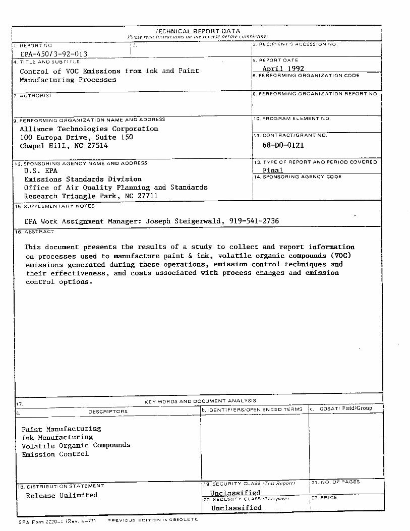
TECHNICAL REPORT DATA /)l,t'USe ¥¢'•2U /tl•lrdCllOttS (IIC rC•'L'P•C OelOP# comrHctl,•£1
I•EPORT NO •:2.
EPA-450 / 3-92-0 t 3 4. TITLE ANOS•BTITLE
Control of V0C Emissions Manufacturing Processes
from ink and Paint
'3. REC:PIENr'% ACCESSION •O
I. REPORT DATE
April 1992 PERFORMING ORGANIZATION CODE
8. PERFORMING ORGANIZ.&TION REPORT NO. 7. AUTHOR(S)
IO. PROGRAM ELEMENT NO. 9. PERFORMING ORGANIZATION NAME AND ADDRESS
ATlia•ce Tectmoiogies Cot•poration 100 Europa Drive, Suite 150 Chapel Hill, NC 27514
12. SPONSORING AGENCY NAME AND ADDRESS
U.S. EPA Emissions Standards Division Office of Air Quality Planning and Standards Research Triangle Park, NC 27711
CONTRACT/GRANT NO.
68-D0-0121
13. TYPE OF REPORT AND PERIOD COVERED FinaZ SPONSORING AGENCY CODE
5. SUPPLEMENTARY NOTES
EPA Work Assignment Manager: Joseph Steigerwaid, 919-541-2736
16. ABSTRACT
This document presents the results of a study to collect and report i•Lformation
on processes used to manufacture paint & ink, volatile organic compounds (VOC) emissions generated during these operations, emission control techniques and their effectiveness, and costs associated with process changes and emission control options.
17. KEY WORDS AND DOCUMENT ANALYSIS
a. DESCRIPTORS b. IDENTIFIERS/OPEN ENDED TERMS c. COSATI Field/Group
Paint Manufacturing Ink Manufacturing Volatile Organic Compounds Emission Control
8. DISTRIBUTION STATEMENT
Release Unlimited 19. SECURITY CLASS /ThisReporrt
Unclassified 21. NO. OF PAGES
20. SECURITY CLASS tThz'spage!
Unclassified 12. PRICE
EPA Form 2220-I (Rev. 4-77• =mEv•ous EDITION OBSOLETE

INSTRUCTIONS
.•EPORT NUMBER
:'.'•C'[[ tile P •, fcpo[t l'tLll]•lOt2[ ll apse 'It's on the cover ot the •uDh...Jtlt)rl.
2. LEAVE BLANK
3. RECIPIENTS ACCESSION NUMBER
Reserved lot u•e by eacil report recipient.
4. TITLE AND SUBTITLE l-tile should indicate clearly and brlel]y the sublecl covcrat:e ol the report, and be dl•pl;IVt.'t.l prOlnlnenlt', ,•ttqlllC. !l l:',,'tl.
•ype or otherwise subordinate it to main title. When report prcparetl in more titan vt)lutnL', rt'p,';it the Drtltl•lIy title. ,•tl',i voiulnt.'
num0er and include subtitle tot the specllic title.
5. REPORT DATE Each report shall carry date indicating at lea•t month and year. Indlt.'ate the ba,.ix •.hlch it ,elected n e. dat•" o] ts.•ttc, date
aoproval, date o[preparatton, etc.I.
6. pERFORMING ORGANIZATION CODE
Leave blank.
7. AUTHORtS) Give namet•l in conventional order (Johtl R. Doe. J. Robert Doc. etc.), t_l authors Jlliliatlon tl it dttIer• tronl the perlormmg organi-
zation.
8. PERFORMING ORGANIZATION REPORT NUMBER
Insert if pertormtng organization wishes to assign this number.
,3. PERFORMING ORGANIZATION NAME AND ADDRESS
Give name, street, city, state, and ZIP code. List no more than two Icveis ol an ortzant,,atluna{ hffcar,.bY.
10. PROGRAM ELEMENT NUMBER Use the program element numoer under which the report was prepared. Subofdul,dt¢ nUlllDL'r', ilt;l•' •.)C IItkitltictl parculhc'•c,.
11. CONTRACT/GRANT NUMBER Insert contract or grant number under which reoort was prepared.
12. SPONSORING AGENCY NAME AND ADDRESS Inctude ZIP code.
13. TYPE OF REPORT AND PERIOD COVERED
Indicate interim final, etc.. and if applicable, dates covered.
14. SPONSORING AGENCY CODE
Insert appropriate code.
15. SUPPLEMENTARY NOTES Enter information not mciu•ed elsewhere but useful, such as: Prepared ill c-ooocratton with, rall,.lallt)H t)l, i)r...'-.vl)lcd al tt)lllt'lt'llt
i'o be published in, Supersecies. Supplements. etc.
16. ABSTRACT Include a brief ?200 words or iessJ factual summary ot the most signltit.'ant information t_.ontalnt.'tl lw tv'u•trt. It tilt" tt'pt)il t)rll;llll\
significant bibliography or nteraturesurvey mentlonlt here.
17. KEY WORDS AND DOCUMENT ANALYSIS
(a) DESCRIPTORS Select from the Thesaurus o( Enatneer'.n• alia Sclcnttl• Fcrtn• me proper autht.rt/cd !t. tltat IdCtltlly the' molar
concept of the research and are surf cientty specific an-d precise to be used mdcx entries tot cataioemg.
(b) IDENTIFIERS .AND OPEN'ENDED TERMS Use identifiers f°r proicct nant•.•.,:odenamcs-cqulpmcnt d,.,t•nators, ctc. U•eupcn-
ended terms written in dcscrt0tor form for those subjects for which no descriptor cxt•ts.
(c) COSATI !-IELD GROLP l. icld and gsoup assignments are to be taken lrom the 1965 ('OS..\I •uhw•,t ce•)ry last. 5,tncc the nla-
jority of documents are muitldisc plinarv tn nature, the Primary Field/Group a•s•gnmcnt(s) will bc "•pc,-Itt,- :jp,.tpitnc. area t)l human
endeavor, or type of piLvstcai object. The applicatlonlsl will be cross-rclcrcnccd with •ct'ondarv tcKI/( ;roup a,,,tgnntcnts that ,*'fll
the primary postingls).
18. DISTRIBUTION STATEMENT Denote reieasabtlity to the puohc or limitation for reasons other than security for c\amplc lo,,..Icasc •i•,•t•v'd." •1•_. a•a]lahd)t•.
the public, with address and price.
19.& 20. SECURITY CLASSIFICATION
DO NOT submit classified rct•orts to tbc National Tcchnlcai Information •crv•cc.
21. NUMBER OF PAGES Insert the total number ol aages, including this one and unnumbered pages, hut c•,cludc dPdrlbutton it•t. il
22. PRICE insert the price set by the Nanonai [ethnical Information Scp, qcc or the Government Printing Office. •
EPA Form 2220-1 (Re-,. 4-77} (Reverse}