epics database principles - aps.anl.gov · pdf filehardware link – a hardware i/o signal...
TRANSCRIPT
EPICS Database Principles
Andrew JohnsonAPS Engineering Support Division
June 2010
USPAS EPICS Course
USPAS June 2010 — EPICS Control Systems — Database Principles
2
Outline
Records Fields and field types Record Scanning Input and Output record types Links, link address types Connecting records together Protection mechanisms Alarms, dead-bands, simulation and security
USPAS June 2010 — EPICS Control Systems — Database Principles
3
Database = Records + Fields + Links
A control system using EPICS will contain one or more IOCs Each IOC loads one or more Databases telling it what to do A Database is a collection of Records of various types A Record is an object with:
– A unique name
– A behavior defined by its record type (class)
– Controllable properties (fields)
– Optional associated hardware I/O (device support)
– Links to other records
USPAS June 2010 — EPICS Control Systems — Database Principles
4
Record Activity
Records are active — they can do things:– Get data from other records or from hardware
– Perform calculations
– Check values are in range & raise alarms
– Put data to other records or to hardware
– Activate or disable other records
– Wait for hardware signals (interrupts)
What a record does depends upon its record type and the settings of its fields
No action occurs unless a record is processed
USPAS June 2010 — EPICS Control Systems — Database Principles
5
How is a Record implemented?
A ‘C’ structure with a data member for each record field– All records start with a standard set of fields (dbCommon) that the system
needs, including pointers to record type information A record definition within a database provides
– Record name
– The record’s type
– Values for each design field
A record type provides– Definitions of all the fields
– Code which implements the record’s behavior
New record types can be added to an application as needed
USPAS June 2010 — EPICS Control Systems — Database Principles
6
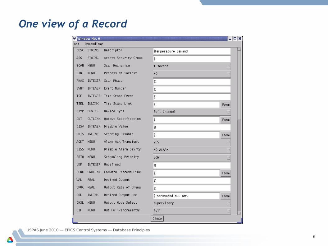
One view of a Record
USPAS June 2010 — EPICS Control Systems — Database Principles
7
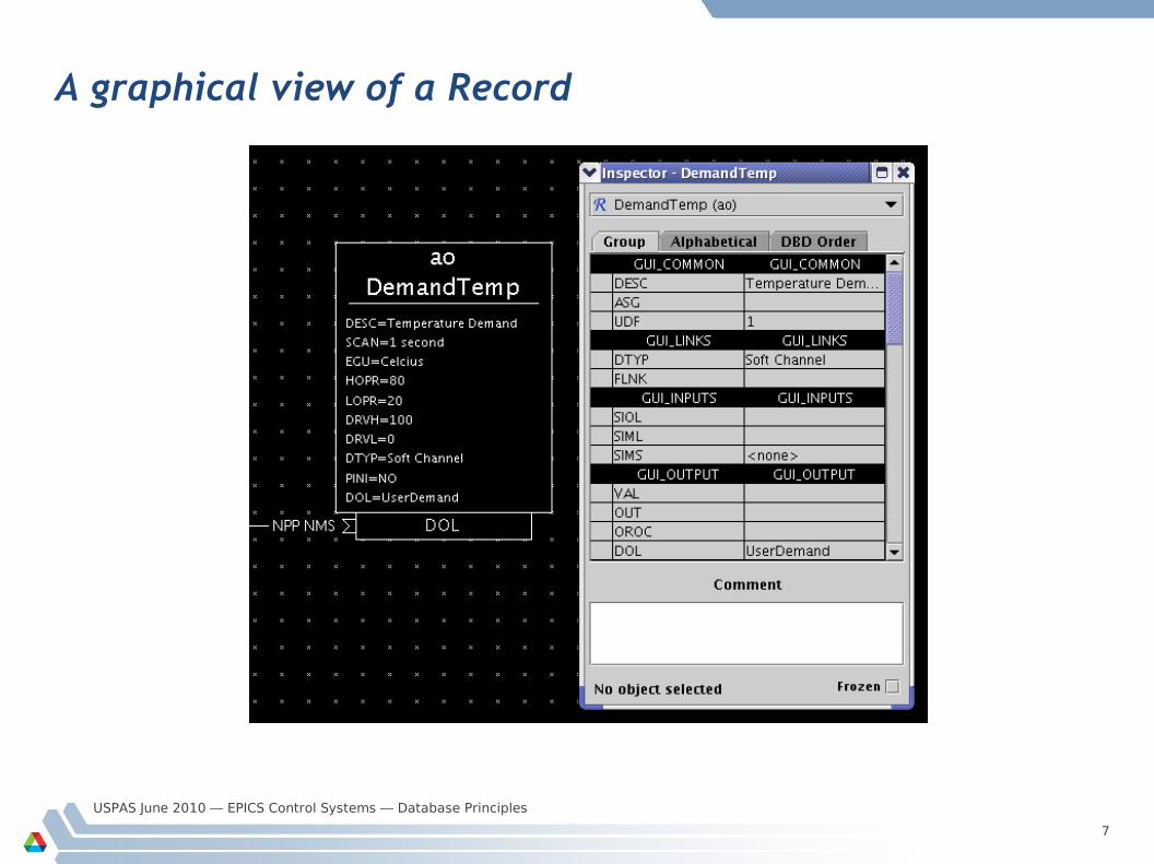
A graphical view of a Record
USPAS June 2010 — EPICS Control Systems — Database Principles
8
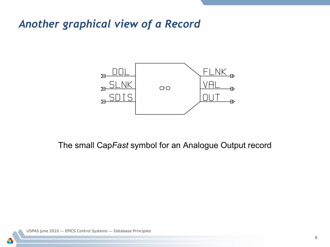
Another graphical view of a Record
The small CapFast symbol for an Analogue Output record
USPAS June 2010 — EPICS Control Systems — Database Principles
9
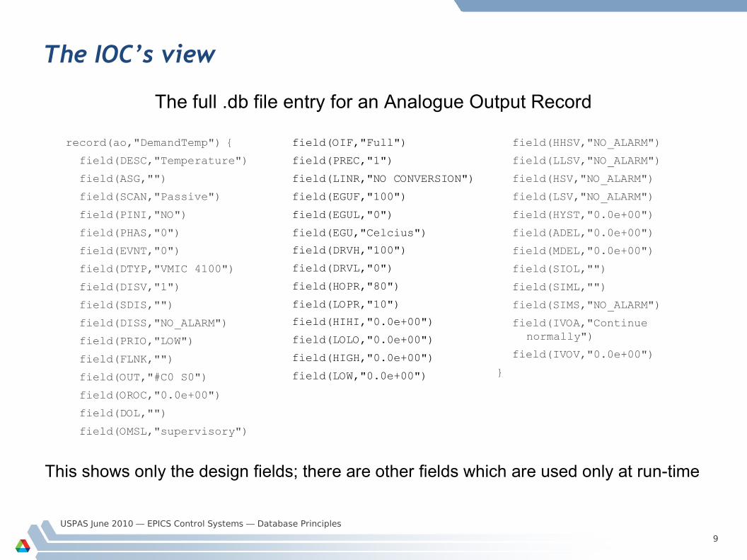
The IOC’s view
record(ao,"DemandTemp") {
field(DESC,"Temperature")
field(ASG,"")
field(SCAN,"Passive")
field(PINI,"NO")
field(PHAS,"0")
field(EVNT,"0")
field(DTYP,"VMIC 4100")
field(DISV,"1")
field(SDIS,"")
field(DISS,"NO_ALARM")
field(PRIO,"LOW")
field(FLNK,"")
field(OUT,"#C0 S0")
field(OROC,"0.0e+00")
field(DOL,"")
field(OMSL,"supervisory")
field(HHSV,"NO_ALARM")
field(LLSV,"NO_ALARM")
field(HSV,"NO_ALARM")
field(LSV,"NO_ALARM")
field(HYST,"0.0e+00")
field(ADEL,"0.0e+00")
field(MDEL,"0.0e+00")
field(SIOL,"")
field(SIML,"")
field(SIMS,"NO_ALARM")
field(IVOA,"Continue normally")
field(IVOV,"0.0e+00")
}
The full .db file entry for an Analogue Output Record
This shows only the design fields; there are other fields which are used only at run-time
field(OIF,"Full")
field(PREC,"1")
field(LINR,"NO CONVERSION")
field(EGUF,"100")
field(EGUL,"0")
field(EGU,"Celcius")
field(DRVH,"100")
field(DRVL,"0")
field(HOPR,"80")
field(LOPR,"10")
field(HIHI,"0.0e+00")
field(LOLO,"0.0e+00")
field(HIGH,"0.0e+00")
field(LOW,"0.0e+00")
USPAS June 2010 — EPICS Control Systems — Database Principles
10
Fields are for...
Defining– What causes a record to process
– Where to get/put data from/to
– How to turn raw I/O data into a numeric engineering value
– Limits indicating when to report an alarm
– When to notify value changes to a client monitoring the record
– A Processing algorithm
– Anything else which needs to be set for each record of a given type
Holding run-time data– Input or output values
– Alarm status, severity and acknowledgments
– Processing time-stamp
– Other data for internal use
USPAS June 2010 — EPICS Control Systems — Database Principles
11
Field types — fields can contain:
Integers– char, short or long– signed or unsigned
Floating-point numbers– float or double
Fixed length strings– maximum useful length is 40
characters
Enumerated/menu choices– select one of up to 16 strings– stored as a short integer
Arrays of any of the above types
Links– to other records in this or other
IOCs– to hardware signals (device
support)– provide a means of getting or
putting a value
Other private data– not accessible remotely
USPAS June 2010 — EPICS Control Systems — Database Principles
12
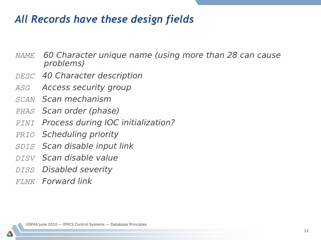
All Records have these design fields
NAME 60 Character unique name (using more than 28 can cause problems)
DESC 40 Character description
ASG Access security groupSCAN Scan mechanism
PHAS Scan order (phase)
PINI Process during IOC initialization?
PRIO Scheduling priority
SDIS Scan disable input link
DISV Scan disable valueDISS Disabled severity
FLNK Forward link
USPAS June 2010 — EPICS Control Systems — Database Principles
13
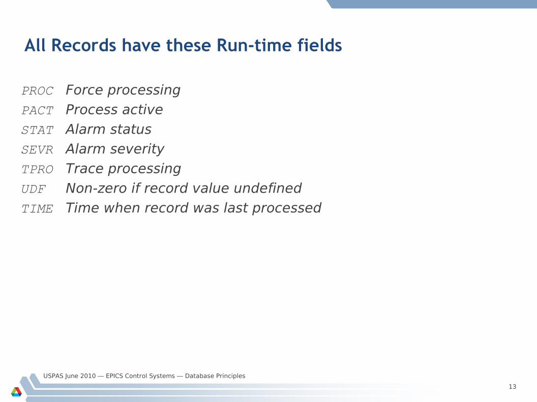
All Records have these Run-time fields
PROC Force processing
PACT Process active
STAT Alarm statusSEVR Alarm severity
TPRO Trace processing
UDF Non-zero if record value undefined
TIME Time when record was last processed
USPAS June 2010 — EPICS Control Systems — Database Principles
14
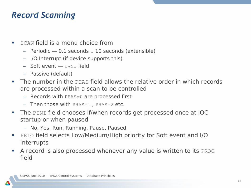
Record Scanning
SCAN field is a menu choice from– Periodic — 0.1 seconds .. 10 seconds (extensible)
– I/O Interrupt (if device supports this)
– Soft event — EVNT field
– Passive (default)
The number in the PHAS field allows the relative order in which records are processed within a scan to be controlled– Records with PHAS=0 are processed first
– Then those with PHAS=1 , PHAS=2 etc.
The PINI field chooses if/when records get processed once at IOC startup or when paused– No, Yes, Run, Running, Pause, Paused
PRIO field selects Low/Medium/High priority for Soft event and I/O Interrupts
A record is also processed whenever any value is written to its PROC field
USPAS June 2010 — EPICS Control Systems — Database Principles
15
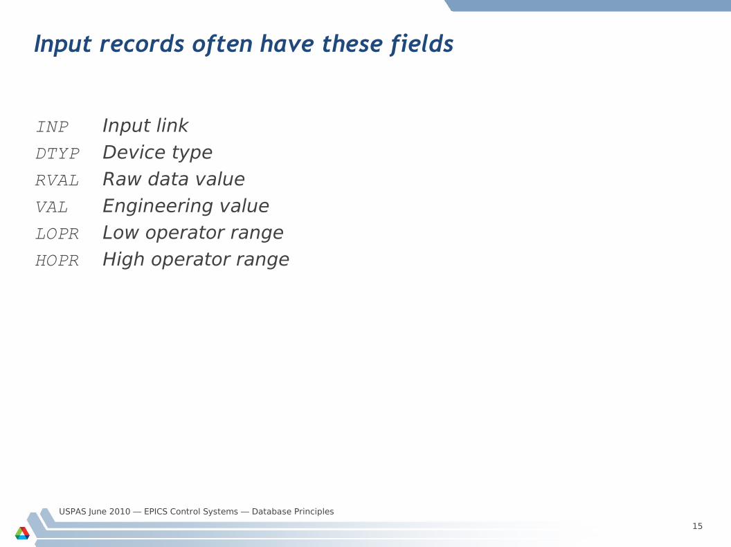
Input records often have these fields
INP Input link
DTYP Device type
RVAL Raw data value
VAL Engineering valueLOPR Low operator range
HOPR High operator range
USPAS June 2010 — EPICS Control Systems — Database Principles
16
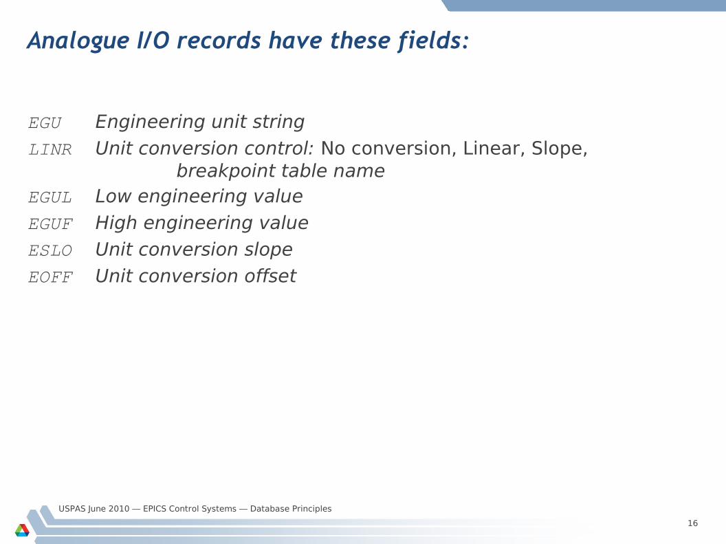
Analogue I/O records have these fields:
EGU Engineering unit string
LINR Unit conversion control: No conversion, Linear, Slope, breakpoint table name
EGUL Low engineering value
EGUF High engineering value
ESLO Unit conversion slope
EOFF Unit conversion offset
USPAS June 2010 — EPICS Control Systems — Database Principles
17
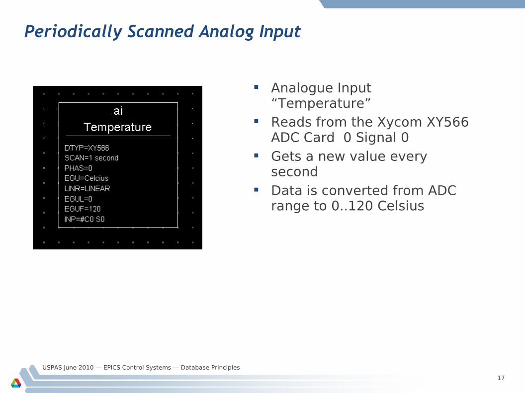
Periodically Scanned Analog Input
Analogue Input “Temperature”
Reads from the Xycom XY566 ADC Card 0 Signal 0
Gets a new value every second
Data is converted from ADC range to 0..120 Celsius
USPAS June 2010 — EPICS Control Systems — Database Principles
18
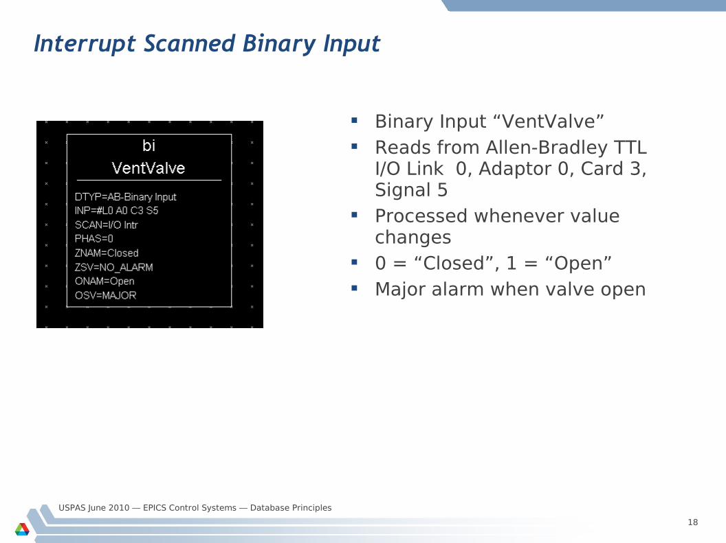
Interrupt Scanned Binary Input
Binary Input “VentValve” Reads from Allen-Bradley TTL
I/O Link 0, Adaptor 0, Card 3, Signal 5
Processed whenever value changes
0 = “Closed”, 1 = “Open” Major alarm when valve open
USPAS June 2010 — EPICS Control Systems — Database Principles
19
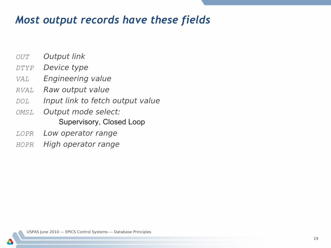
Most output records have these fields
OUT Output link
DTYP Device type
VAL Engineering value
RVAL Raw output value
DOL Input link to fetch output value
OMSL Output mode select:Supervisory, Closed Loop
LOPR Low operator range
HOPR High operator range
USPAS June 2010 — EPICS Control Systems — Database Principles
20
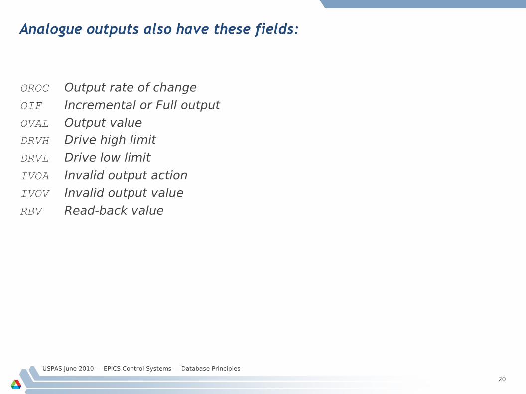
Analogue outputs also have these fields:
OROC Output rate of change
OIF Incremental or Full output
OVAL Output value
DRVH Drive high limit
DRVL Drive low limit
IVOA Invalid output action
IVOV Invalid output value
RBV Read-back value
USPAS June 2010 — EPICS Control Systems — Database Principles
21
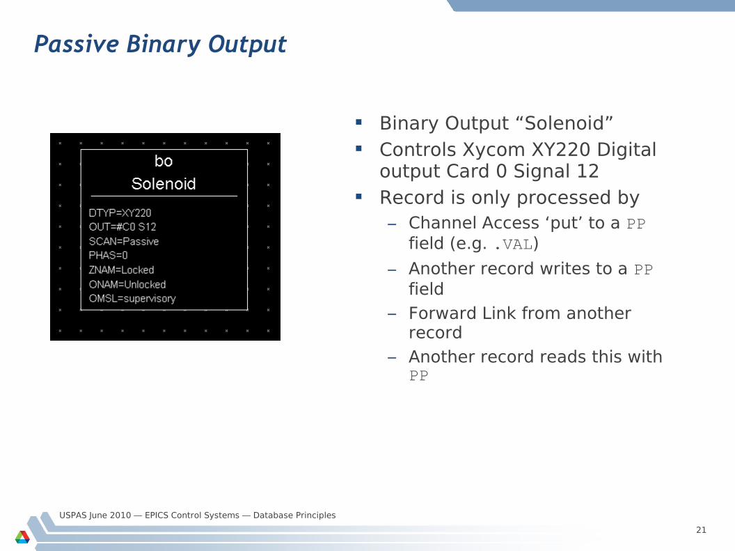
Passive Binary Output
Binary Output “Solenoid” Controls Xycom XY220 Digital
output Card 0 Signal 12 Record is only processed by
– Channel Access ‘put’ to a PP field (e.g. .VAL)
– Another record writes to a PP field
– Forward Link from another record
– Another record reads this with PP

USPAS June 2010 — EPICS Control Systems — Database Principles
22
Break time...
5 Minute break
USPAS June 2010 — EPICS Control Systems — Database Principles
23
Links
A link is a type of field, and is one of Input link
– Fetches data
Output link– Writes data
Forward link– Points to the record to be processed once this record finishes processing
USPAS June 2010 — EPICS Control Systems — Database Principles
24
Input and Output links may be...
Constant numeric value, e.g.:0
3.1415926536
-1.6e-19 Hardware link
– A hardware I/O signal selector, the format of which depends on the device support layer
Process Variable link — the name of a record, which at run-time is resolved into– Database link
• Named record is in this IOC
– Channel Access link• Named record not found in this IOC
USPAS June 2010 — EPICS Control Systems — Database Principles
25
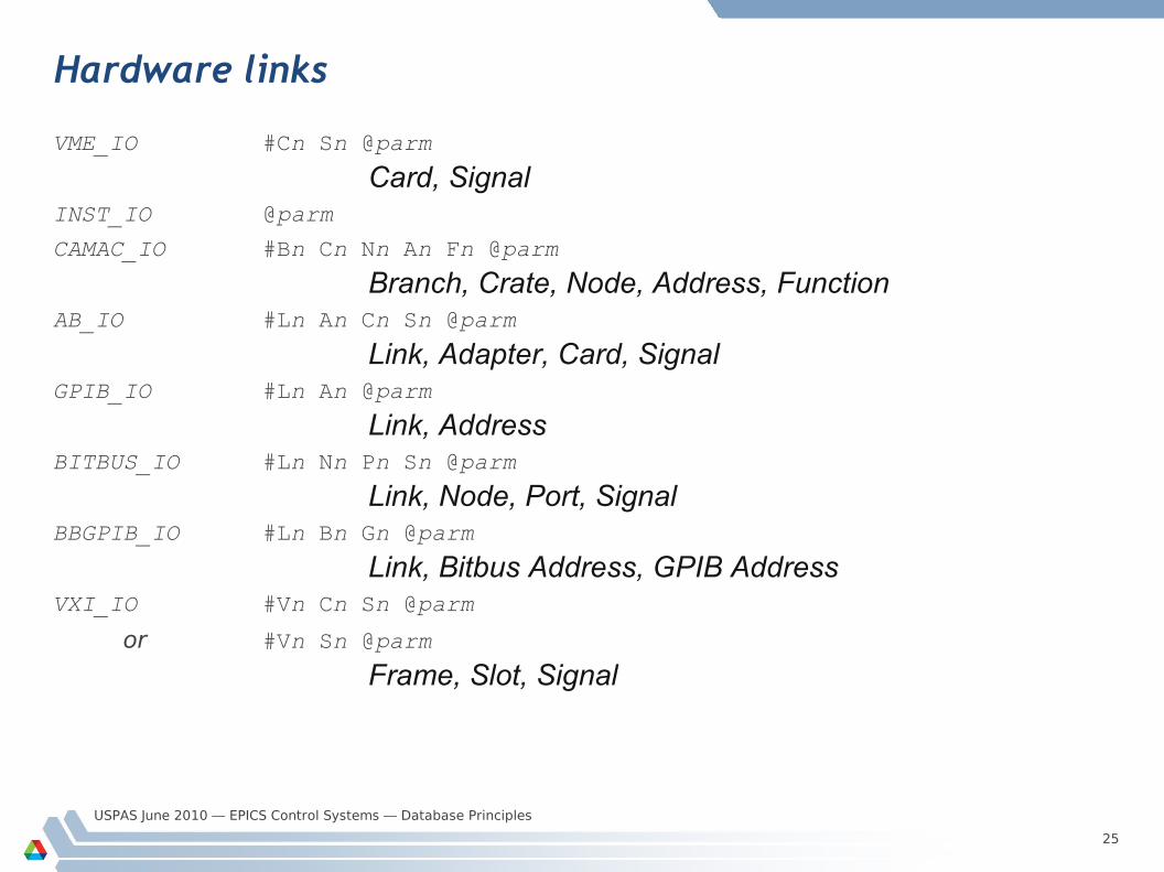
Hardware links
VME_IO #Cn Sn @parm
Card, SignalINST_IO @parm
CAMAC_IO #Bn Cn Nn An Fn @parm
Branch, Crate, Node, Address, FunctionAB_IO #Ln An Cn Sn @parm
Link, Adapter, Card, SignalGPIB_IO #Ln An @parm
Link, AddressBITBUS_IO #Ln Nn Pn Sn @parm
Link, Node, Port, SignalBBGPIB_IO #Ln Bn Gn @parm
Link, Bitbus Address, GPIB AddressVXI_IO #Vn Cn Sn @parm
or #Vn Sn @parm
Frame, Slot, Signal
USPAS June 2010 — EPICS Control Systems — Database Principles
26
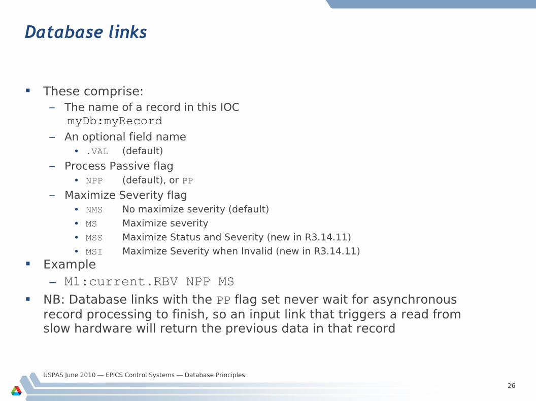
Database links
These comprise:– The name of a record in this IOC
myDb:myRecord– An optional field name
• .VAL (default)
– Process Passive flag• NPP (default), or PP
– Maximize Severity flag• NMS No maximize severity (default)
• MS Maximize severity
• MSS Maximize Status and Severity (new in R3.14.11)
• MSI Maximize Severity when Invalid (new in R3.14.11) Example
– M1:current.RBV NPP MS NB: Database links with the PP flag set never wait for asynchronous
record processing to finish, so an input link that triggers a read from slow hardware will return the previous data in that record
USPAS June 2010 — EPICS Control Systems — Database Principles
27
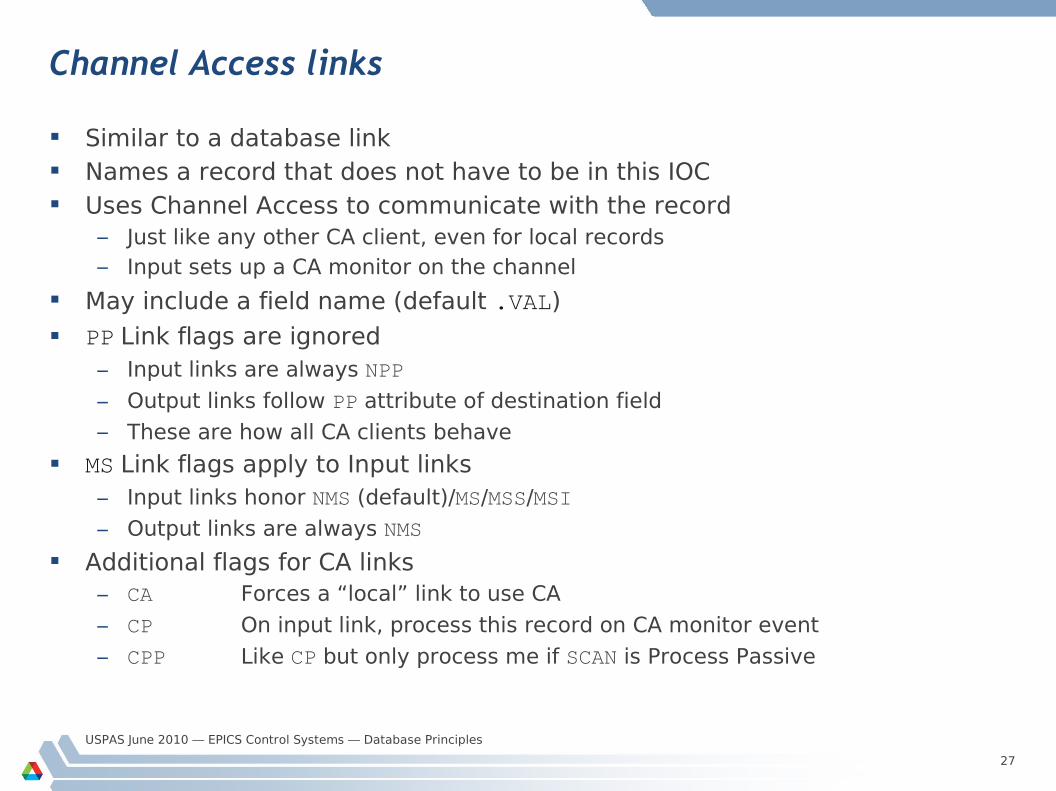
Channel Access links
Similar to a database link Names a record that does not have to be in this IOC Uses Channel Access to communicate with the record
– Just like any other CA client, even for local records– Input sets up a CA monitor on the channel
May include a field name (default .VAL)
PP Link flags are ignored– Input links are always NPP
– Output links follow PP attribute of destination field
– These are how all CA clients behave
MS Link flags apply to Input links– Input links honor NMS (default)/MS/MSS/MSI
– Output links are always NMS
Additional flags for CA links– CA Forces a “local” link to use CA
– CP On input link, process this record on CA monitor event
– CPP Like CP but only process me if SCAN is Process Passive
USPAS June 2010 — EPICS Control Systems — Database Principles
28
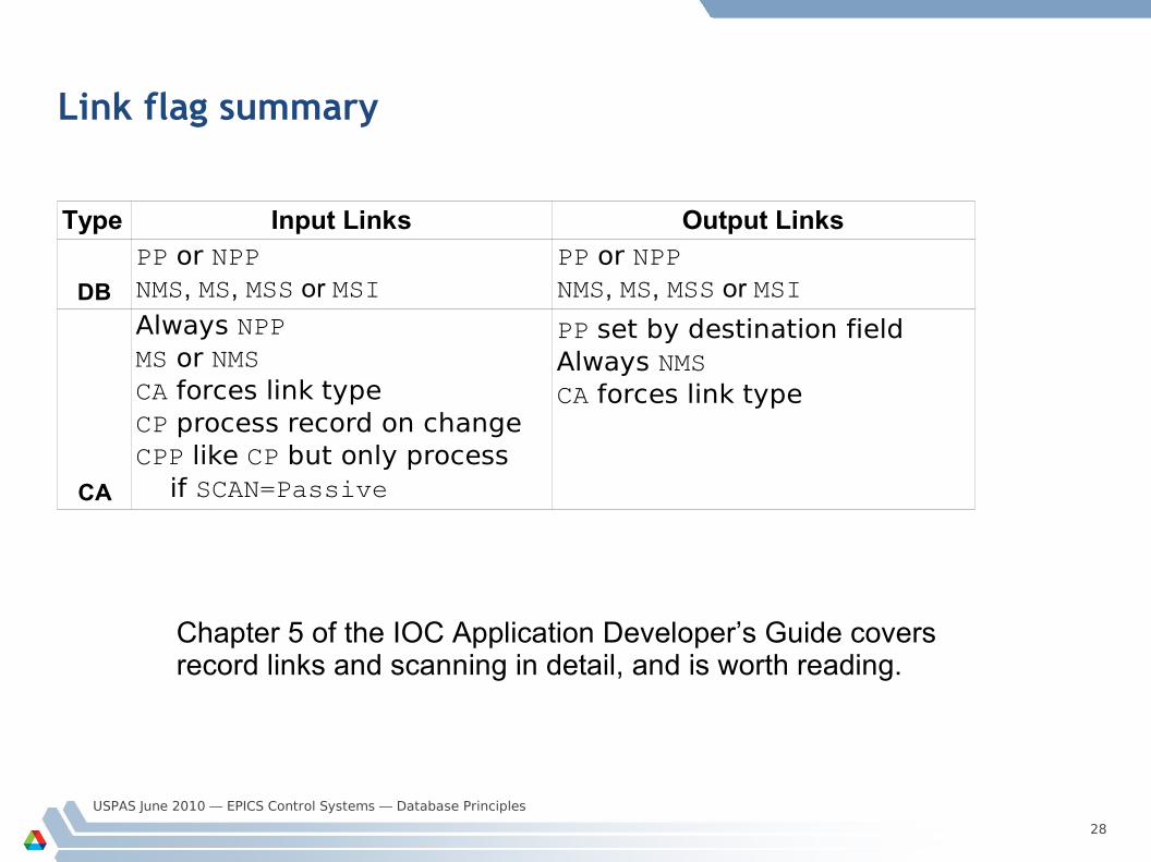
Link flag summary
Type Input Links Output Links
DB
CA
PP or NPPNMS, MS, MSS or MSI
PP or NPPNMS, MS, MSS or MSI
Always NPPMS or NMSCA forces link typeCP process record on changeCPP like CP but only process if SCAN=Passive
PP set by destination fieldAlways NMSCA forces link type
Chapter 5 of the IOC Application Developer’s Guide covers record links and scanning in detail, and is worth reading.
USPAS June 2010 — EPICS Control Systems — Database Principles
29
Device Support
Records do not access hardware directly The Device Support layer performs I/O operations on request
– Each device support performs I/O for one record type
A record’s DTYP field determines which device support it uses– Most record types default to Soft Channel support if you don’t set DTYP
The device support selected determines the format of the link (INP or OUT field) containing the device address
Adding new device support does not require any changes or recompilation of the record type code
Device support often calls other software to do work for it (Driver Support or other libraries)
USPAS June 2010 — EPICS Control Systems — Database Principles
30
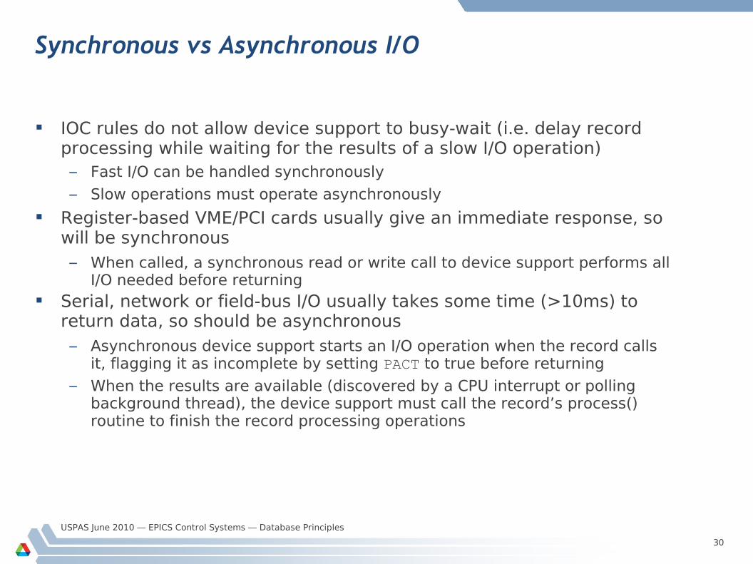
Synchronous vs Asynchronous I/O
IOC rules do not allow device support to busy-wait (i.e. delay record processing while waiting for the results of a slow I/O operation)– Fast I/O can be handled synchronously
– Slow operations must operate asynchronously
Register-based VME/PCI cards usually give an immediate response, so will be synchronous– When called, a synchronous read or write call to device support performs all
I/O needed before returning Serial, network or field-bus I/O usually takes some time (>10ms) to
return data, so should be asynchronous– Asynchronous device support starts an I/O operation when the record calls
it, flagging it as incomplete by setting PACT to true before returning
– When the results are available (discovered by a CPU interrupt or polling background thread), the device support must call the record’s process() routine to finish the record processing operations
USPAS June 2010 — EPICS Control Systems — Database Principles
31
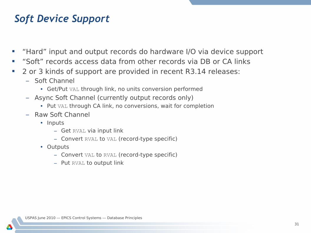
Soft Device Support
“Hard” input and output records do hardware I/O via device support “Soft” records access data from other records via DB or CA links 2 or 3 kinds of support are provided in recent R3.14 releases:
– Soft Channel• Get/Put VAL through link, no units conversion performed
– Async Soft Channel (currently output records only)• Put VAL through CA link, no conversions, wait for completion
– Raw Soft Channel• Inputs
– Get RVAL via input link
– Convert RVAL to VAL (record-type specific)
• Outputs
– Convert VAL to RVAL (record-type specific)
– Put RVAL to output link
USPAS June 2010 — EPICS Control Systems — Database Principles
32
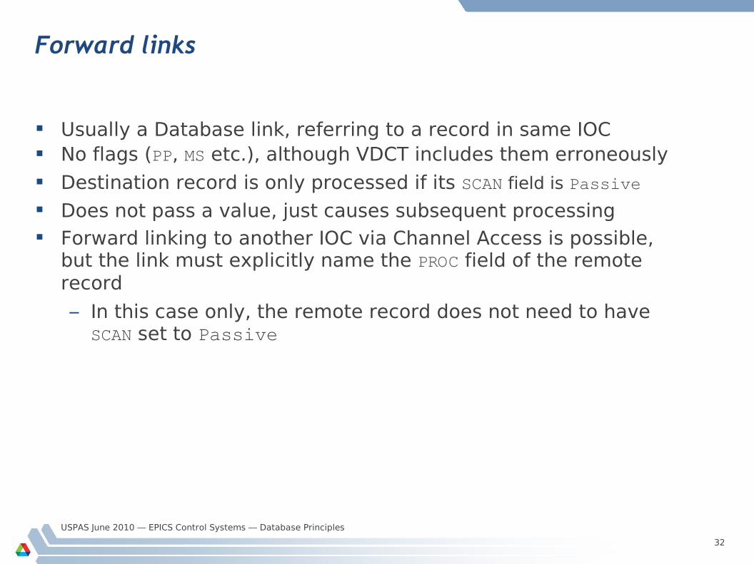
Forward links
Usually a Database link, referring to a record in same IOC No flags (PP, MS etc.), although VDCT includes them erroneously
Destination record is only processed if its SCAN field is Passive
Does not pass a value, just causes subsequent processing Forward linking to another IOC via Channel Access is possible,
but the link must explicitly name the PROC field of the remote record
– In this case only, the remote record does not need to have SCAN set to Passive
USPAS June 2010 — EPICS Control Systems — Database Principles
33
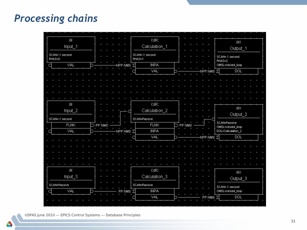
Processing chains
USPAS June 2010 — EPICS Control Systems — Database Principles
34
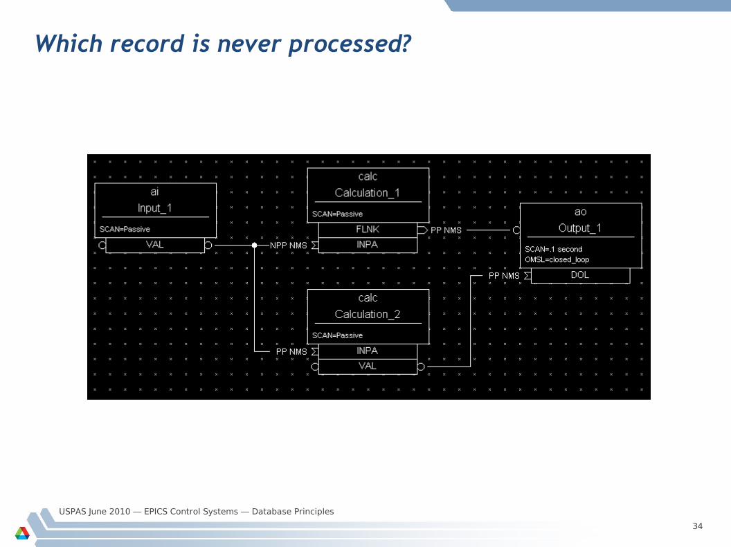
Which record is never processed?
USPAS June 2010 — EPICS Control Systems — Database Principles
35
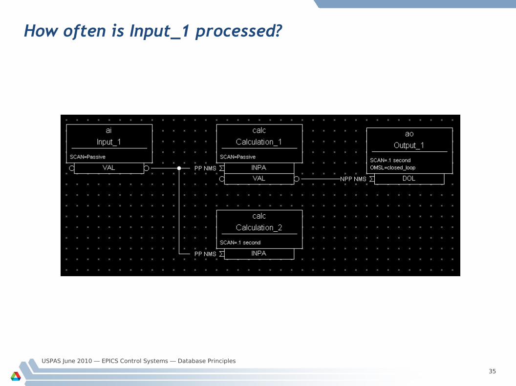
How often is Input_1 processed?
USPAS June 2010 — EPICS Control Systems — Database Principles
36
The PACT field
Every record has a boolean run-time field called PACT (Process Active)
PACT breaks loops of linked records It is set to true early in the act of processing the record (but it's
not the first thing that the process routine does)
– PACT should always be true whenever a link in that record is used to get/put a value
PACT gets reset to false after all record I/O and forward link processing are finished
A PP link can never make a record process if it has PACT true
– Input links will take the current field value– Output links just put their value to the field
USPAS June 2010 — EPICS Control Systems — Database Principles
37
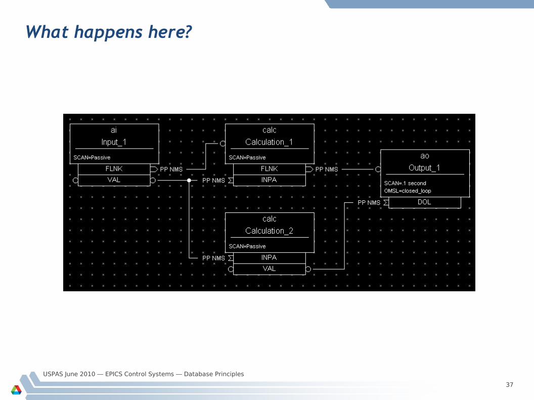
What happens here?
USPAS June 2010 — EPICS Control Systems — Database Principles
38
Preventing records from processing
It is useful to be able to stop an individual record from processing on some condition
Before record-specific processing is called, a value is read through the SDIS input link into DISA (which defaults to 0 if the link is not set)
If DISA=DISV, the record will not be processed
The default value of the DISV field is 1 A disabled record may be put into an alarm state by giving the
desired severity in the DISS field
The FLNK of a disabled record is never triggered
USPAS June 2010 — EPICS Control Systems — Database Principles
39
Break time...
5 Minute break
USPAS June 2010 — EPICS Control Systems — Database Principles
40
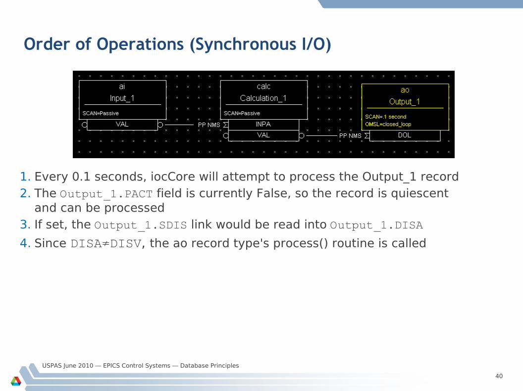
Order of Operations (Synchronous I/O)
1. Every 0.1 seconds, iocCore will attempt to process the Output_1 record2. The Output_1.PACT field is currently False, so the record is quiescent
and can be processed3. If set, the Output_1.SDIS link would be read into Output_1.DISA
4. Since DISA≠DISV, the ao record type's process() routine is called
USPAS June 2010 — EPICS Control Systems — Database Principles
41
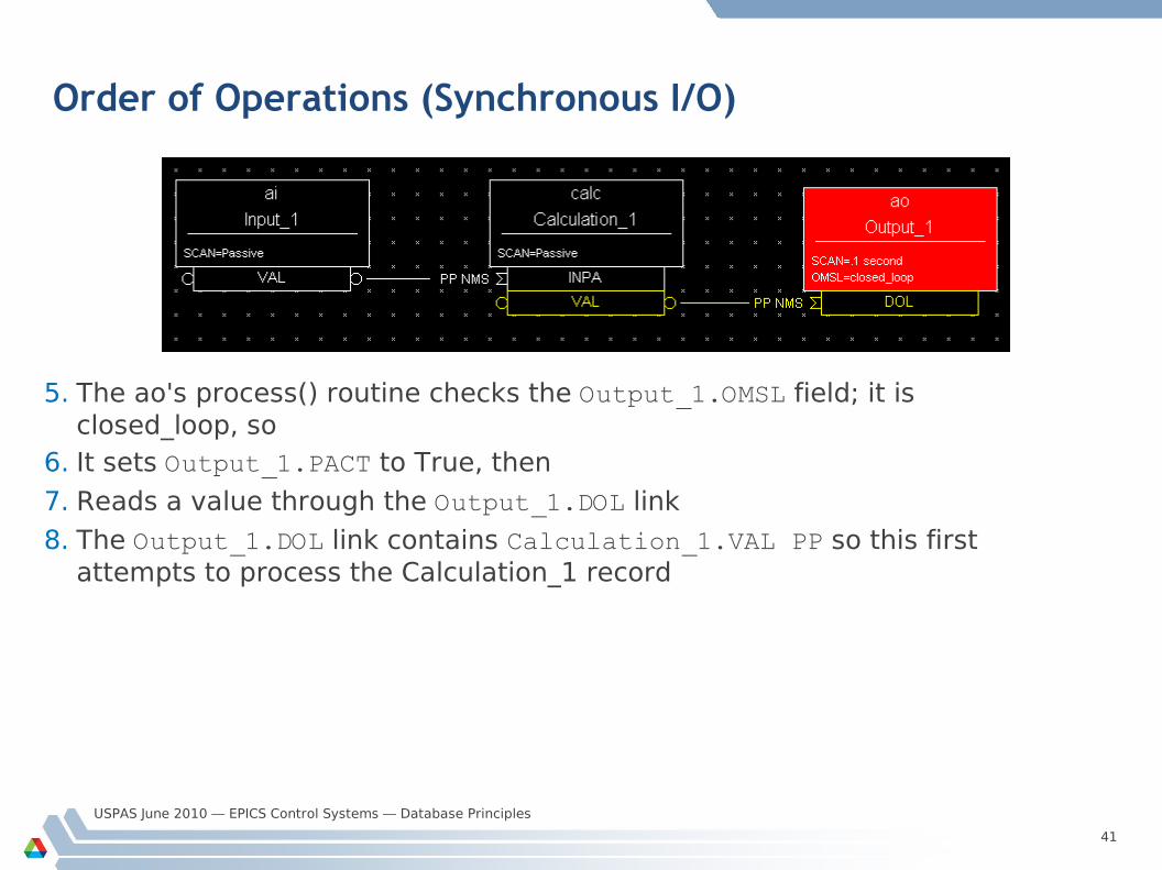
Order of Operations (Synchronous I/O)
5. The ao's process() routine checks the Output_1.OMSL field; it is closed_loop, so
6. It sets Output_1.PACT to True, then
7. Reads a value through the Output_1.DOL link
8. The Output_1.DOL link contains Calculation_1.VAL PP so this first attempts to process the Calculation_1 record
USPAS June 2010 — EPICS Control Systems — Database Principles
42
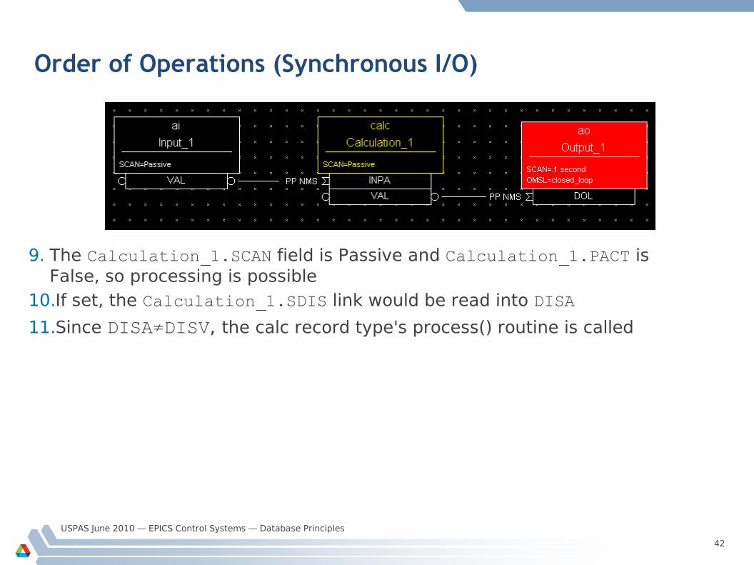
Order of Operations (Synchronous I/O)
9. The Calculation_1.SCAN field is Passive and Calculation_1.PACT is False, so processing is possible
10.If set, the Calculation_1.SDIS link would be read into DISA
11.Since DISA≠DISV, the calc record type's process() routine is called
USPAS June 2010 — EPICS Control Systems — Database Principles
43
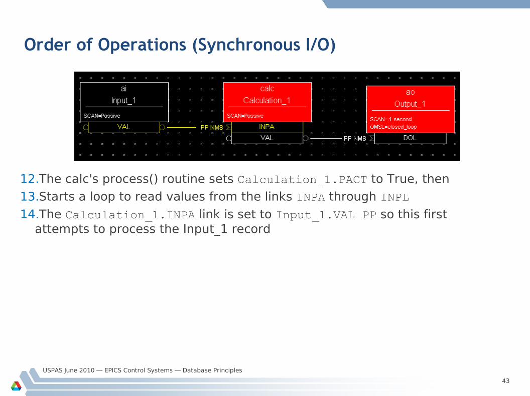
Order of Operations (Synchronous I/O)
12.The calc's process() routine sets Calculation_1.PACT to True, then
13.Starts a loop to read values from the links INPA through INPL
14.The Calculation_1.INPA link is set to Input_1.VAL PP so this first attempts to process the Input_1 record
USPAS June 2010 — EPICS Control Systems — Database Principles
44
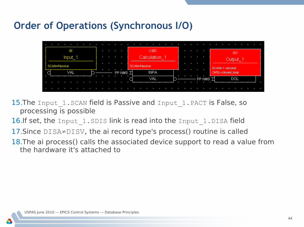
Order of Operations (Synchronous I/O)
15.The Input_1.SCAN field is Passive and Input_1.PACT is False, so processing is possible
16.If set, the Input_1.SDIS link is read into the Input_1.DISA field
17.Since DISA≠DISV, the ai record type's process() routine is called
18.The ai process() calls the associated device support to read a value from the hardware it's attached to
USPAS June 2010 — EPICS Control Systems — Database Principles
45
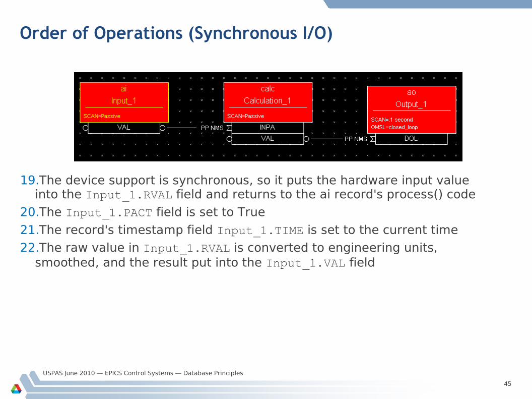
Order of Operations (Synchronous I/O)
19.The device support is synchronous, so it puts the hardware input value into the Input_1.RVAL field and returns to the ai record's process() code
20.The Input_1.PACT field is set to True
21.The record's timestamp field Input_1.TIME is set to the current time
22.The raw value in Input_1.RVAL is converted to engineering units, smoothed, and the result put into the Input_1.VAL field
USPAS June 2010 — EPICS Control Systems — Database Principles
46
Order of Operations (Synchronous I/O)
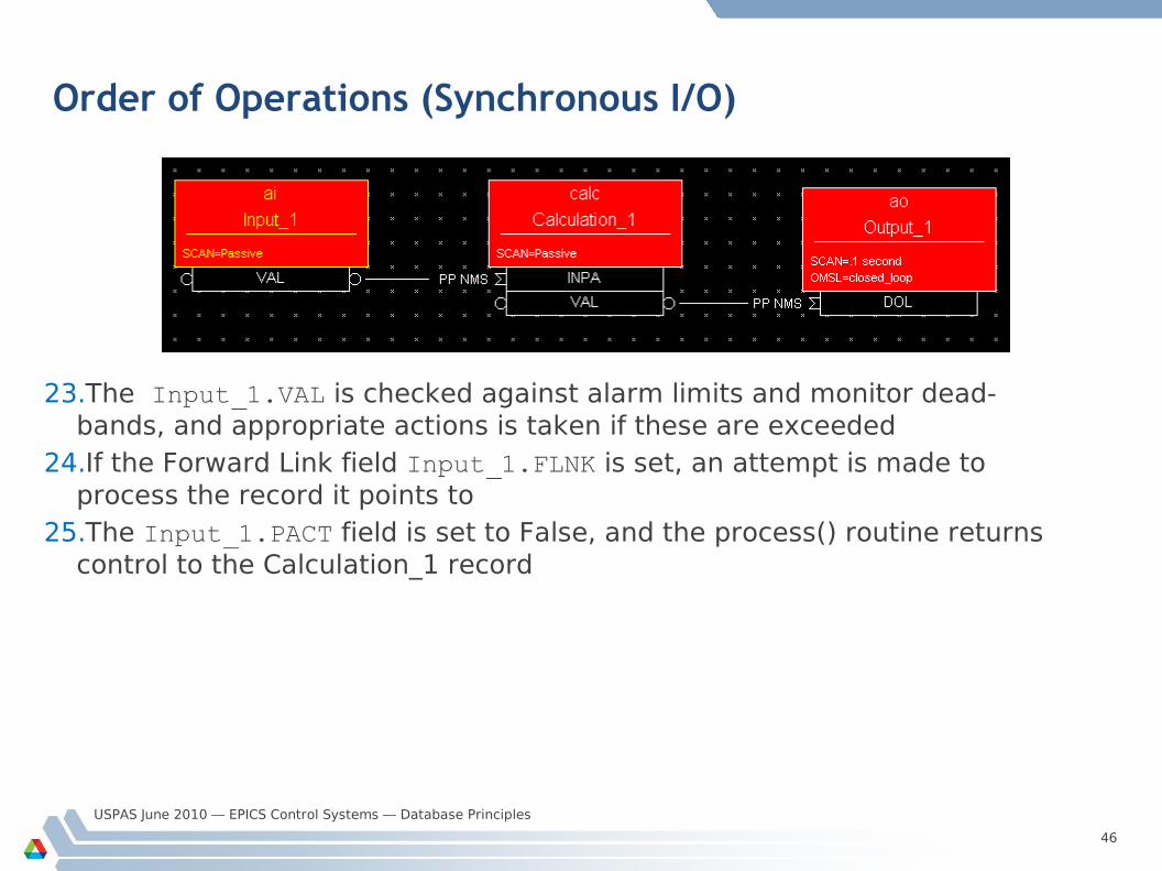
23.The Input_1.VAL is checked against alarm limits and monitor dead-bands, and appropriate actions is taken if these are exceeded
24.If the Forward Link field Input_1.FLNK is set, an attempt is made to process the record it points to
25.The Input_1.PACT field is set to False, and the process() routine returns control to the Calculation_1 record
USPAS June 2010 — EPICS Control Systems — Database Principles
47
Order of Operations (Synchronous I/O)
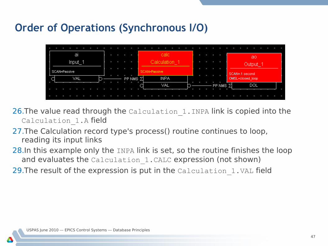
26.The value read through the Calculation_1.INPA link is copied into the Calculation_1.A field
27.The Calculation record type's process() routine continues to loop, reading its input links
28.In this example only the INPA link is set, so the routine finishes the loop and evaluates the Calculation_1.CALC expression (not shown)
29.The result of the expression is put in the Calculation_1.VAL field
USPAS June 2010 — EPICS Control Systems — Database Principles
48
Order of Operations (Synchronous I/O)
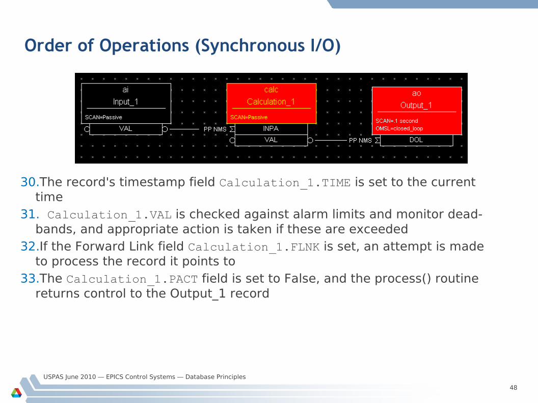
30.The record's timestamp field Calculation_1.TIME is set to the current time
31. Calculation_1.VAL is checked against alarm limits and monitor dead-bands, and appropriate action is taken if these are exceeded
32.If the Forward Link field Calculation_1.FLNK is set, an attempt is made to process the record it points to
33.The Calculation_1.PACT field is set to False, and the process() routine returns control to the Output_1 record
USPAS June 2010 — EPICS Control Systems — Database Principles
49
Order of Operations (Synchronous I/O)
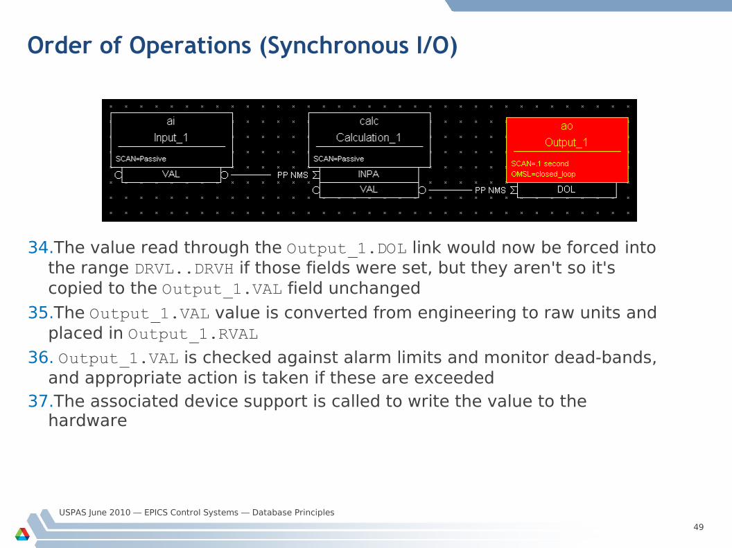
34.The value read through the Output_1.DOL link would now be forced into the range DRVL..DRVH if those fields were set, but they aren't so it's copied to the Output_1.VAL field unchanged
35.The Output_1.VAL value is converted from engineering to raw units and placed in Output_1.RVAL
36. Output_1.VAL is checked against alarm limits and monitor dead-bands, and appropriate action is taken if these are exceeded
37.The associated device support is called to write the value to the hardware
USPAS June 2010 — EPICS Control Systems — Database Principles
50
Order of Operations (Synchronous I/O)
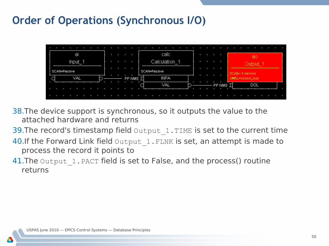
38.The device support is synchronous, so it outputs the value to the attached hardware and returns
39.The record's timestamp field Output_1.TIME is set to the current time
40.If the Forward Link field Output_1.FLNK is set, an attempt is made to process the record it points to
41.The Output_1.PACT field is set to False, and the process() routine returns
USPAS June 2010 — EPICS Control Systems — Database Principles
51
How are records given CPU time?
Several IOC tasks are used: callback (3 priorities) — I/O Interrupt scanEvent — Soft Event scanPeriod — Periodic
– A separate task is used for each scan period– Faster scan rates are given a higher task priority (if
supported by the IOC’s Operating System) Channel Access tasks use lower priority than record processing
– If a CPU spends all its time doing I/O and record processing, you may be unable to control or monitor the IOC via the network
USPAS June 2010 — EPICS Control Systems — Database Principles
52
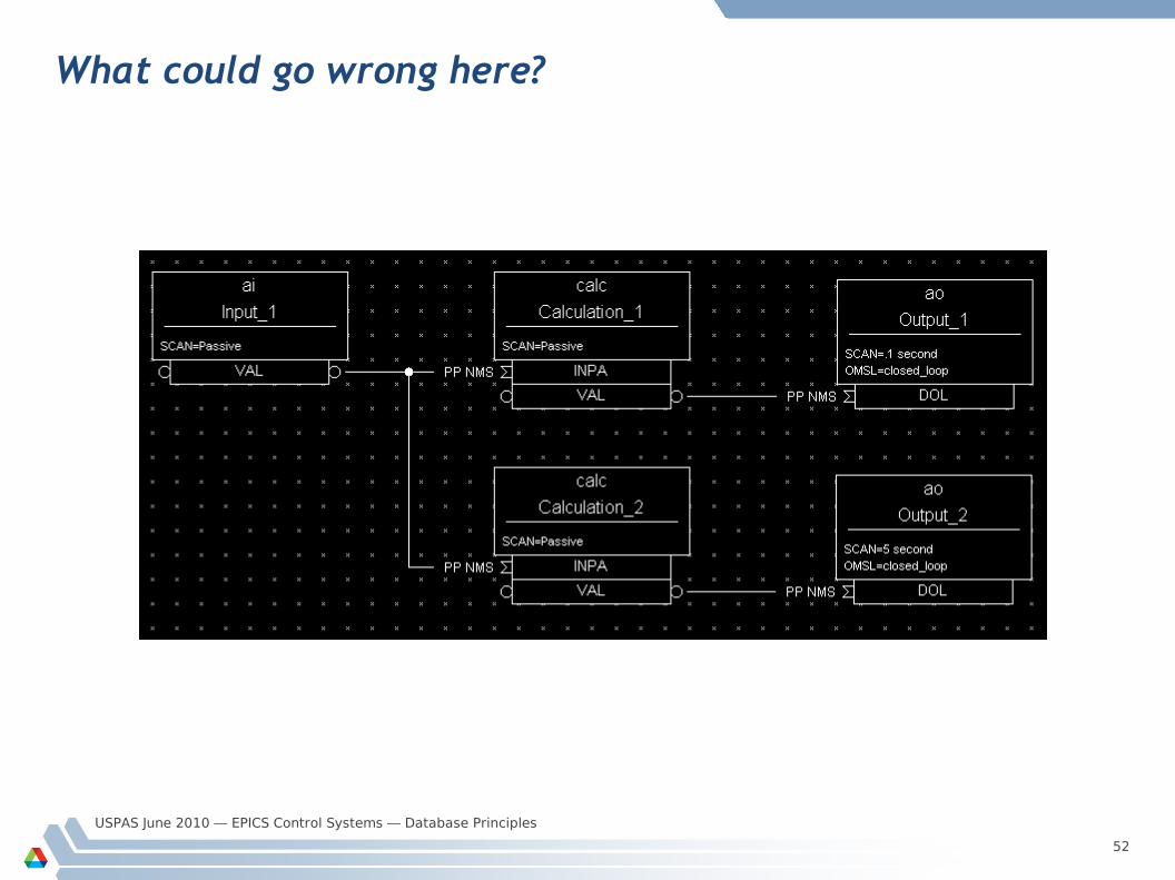
What could go wrong here?
USPAS June 2010 — EPICS Control Systems — Database Principles
53
Lock-sets
Prevent records from being processed simultaneously by two different scan tasks– PACT can’t do that, it isn’t set early enough and is not a Mutex
A lock-set is a group of records interconnected by database links Lock-sets are determined automatically by the IOC at start-up, or
whenever a database link is added, deleted or modified You can split two linked records into different lock sets by making the
link(s) joining them into Channel Access ones, using the CA flag
– Remember that CA links behave slightly differently than DB links, make sure your design still works!
USPAS June 2010 — EPICS Control Systems — Database Principles
54
Alarms
Every record has the fields– SEVR Alarm Severity
• NONE, MINOR, MAJOR, INVALID
– STAT Alarm Status (reason)• READ, WRITE, UDF, HIGH, LOW, STATE, COS, CALC, DISABLE, etc.
Most numeric records compare VAL against the HIHI, HIGH, LOW and LOLO fields after its value has been determined
The HYST field sets a hysteresis to prevent alarm chattering
A separate alarm severity can be set for each numeric limit exceeded– Fields HHSV, HSV, LSV, and LLSV
Discrete (binary) records can raise alarms on entering a particular state, or on a change of state (COS)
USPAS June 2010 — EPICS Control Systems — Database Principles
55
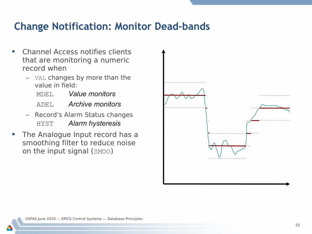
Change Notification: Monitor Dead-bands
Channel Access notifies clients that are monitoring a numeric record when– VAL changes by more than the
value in field:MDEL Value monitors
ADEL Archive monitors
– Record’s Alarm Status changesHYST Alarm hysteresis
The Analogue Input record has a smoothing filter to reduce noise on the input signal (SMOO)
USPAS June 2010 — EPICS Control Systems — Database Principles
56
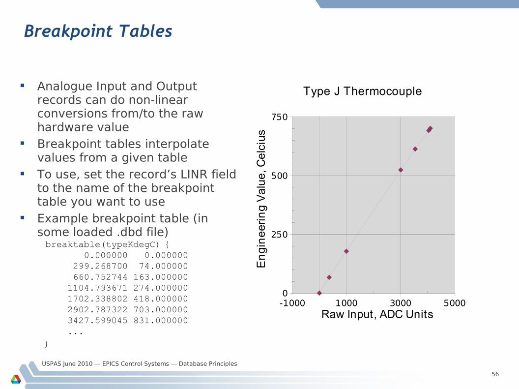
Breakpoint Tables
Analogue Input and Output records can do non-linear conversions from/to the raw hardware value
Breakpoint tables interpolate values from a given table
To use, set the record’s LINR field to the name of the breakpoint table you want to use
Example breakpoint table (in some loaded .dbd file)breaktable(typeKdegC) { 0.000000 0.000000 299.268700 74.000000 660.752744 163.000000 1104.793671 274.000000 1702.338802 418.000000 2902.787322 703.000000 3427.599045 831.000000 ...}
-1000 1000 3000 50000
250
500
750
Type J Thermocouple
Raw Input, ADC Units
En
gin
ee
rin
g V
alu
e, C
elc
ius
USPAS June 2010 — EPICS Control Systems — Database Principles
57
Simulation
Input and output record types often allow simulation of hardware interfacesSIML Simulation mode link
SIMM Simulation mode value
SIOL Simulation input link
SVAL Simulated value
SIMS Simulation alarm severity
Before calling device support, records read SIMM through the SIML link
If SIMM=YES (1) or RAW (2) the device support is not used; record I/O is done through the SIOL link and SVAL field instead
An alarm severity can be set whenever simulating, given by SIMS field
USPAS June 2010 — EPICS Control Systems — Database Principles
58
Access Security
A networked control system must have the ability to enforce security rules– Who can do what from where, and when?
In EPICS, security is enforced by the CA server (the IOC or gateway) A record is placed in the Access Security Group named in its ASG field
– DEFAULT is used if no group name is given
Rules are specified for each group to determine whether a CA client can read or write to records in that group, based on– Client user ID
– Client host-name or IP address
– Access Security Level of the field addressed
– Values read from the database
USPAS June 2010 — EPICS Control Systems — Database Principles
59
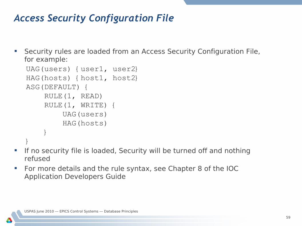
Access Security Configuration File
Security rules are loaded from an Access Security Configuration File, for example:UAG(users) {user1, user2}HAG(hosts) {host1, host2}ASG(DEFAULT) { RULE(1, READ) RULE(1, WRITE) { UAG(users) HAG(hosts) }}
If no security file is loaded, Security will be turned off and nothing refused
For more details and the rule syntax, see Chapter 8 of the IOC Application Developers Guide