epri cim for dynamic models project report -...
TRANSCRIPT
EPRI CIM for Dynamic Models Project Report
Terry Saxton Xtensible SolutionsNovember 11, 2009

EPRI CIM for Dynamic Models
2
CIM for Dynamic Models
EPRI project – started March 2008Project Objectives
– Develop a standard way to exchange dynamic models for each generator, load or other resource in a power system network
Technical Approach – Extend the CIM and develop a set of interface profiles to
support the exchange of dynamic cases (dynamic models and associated static network models)
– Builds from the EPRI CIM for Planning project extensions to the CIM UML
Challenge– How to model the interconnectivity between dynamic
models and their association to the static network model
EPRI CIM for Dynamic Models
3
Business Needs Addressed
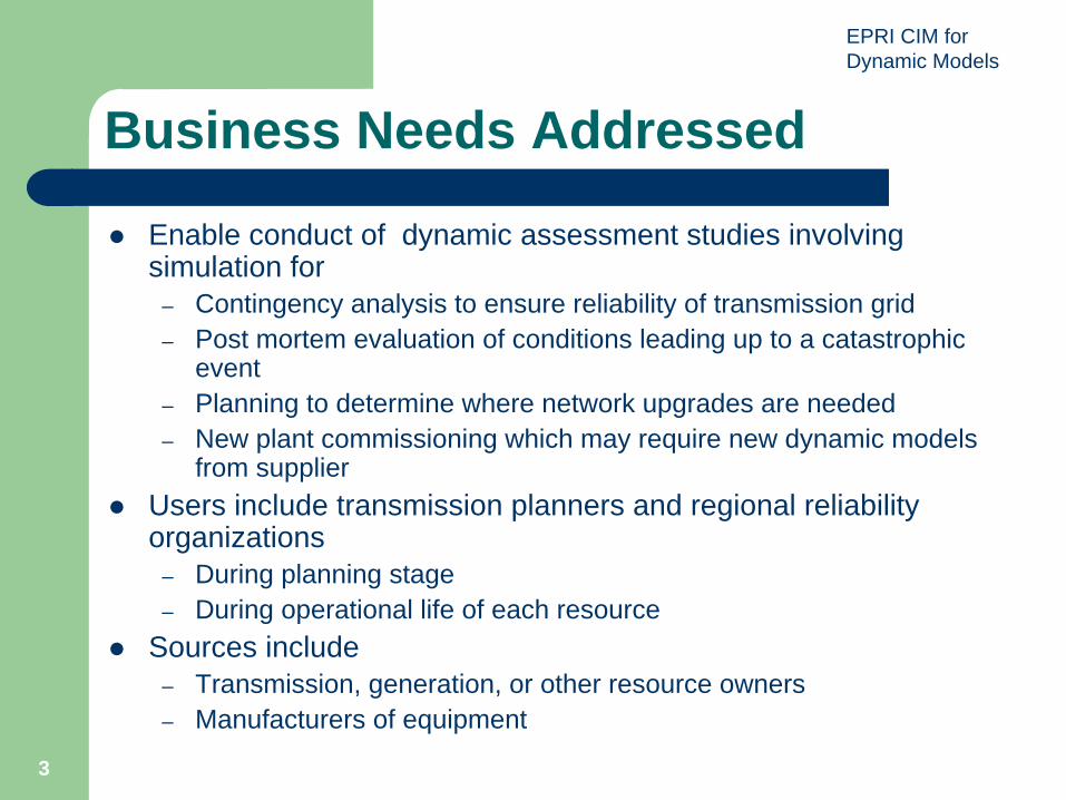
Enable conduct of dynamic assessment studies involving simulation for
– Contingency analysis to ensure reliability of transmission grid– Post mortem evaluation of conditions leading up to a catastrophic
event– Planning to determine where network upgrades are needed– New plant commissioning which may require new dynamic models
from supplierUsers include transmission planners and regional reliability organizations
– During planning stage– During operational life of each resource
Sources include– Transmission, generation, or other resource owners– Manufacturers of equipment
EPRI CIM for Dynamic Models
4
Status of Key Deliverables
UCTE IOP TestDynamic Case DefinitionStandard Model exchangeUser-Defined Model exchangeCIM modeling
EPRI CIM for Dynamic Models
Dynamic Case Definition – Profile Contents
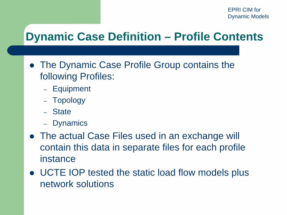
The Dynamic Case Profile Group contains the following Profiles:
– Equipment– Topology– State– Dynamics
The actual Case Files used in an exchange will contain this data in separate files for each profile instanceUCTE IOP tested the static load flow models plus network solutions

EPRI CIM for Dynamic Models
Dynamic Case Contents – UCTE Base
EPRI CIM for Dynamic Models
Dynamic Case Definition – Case Composition
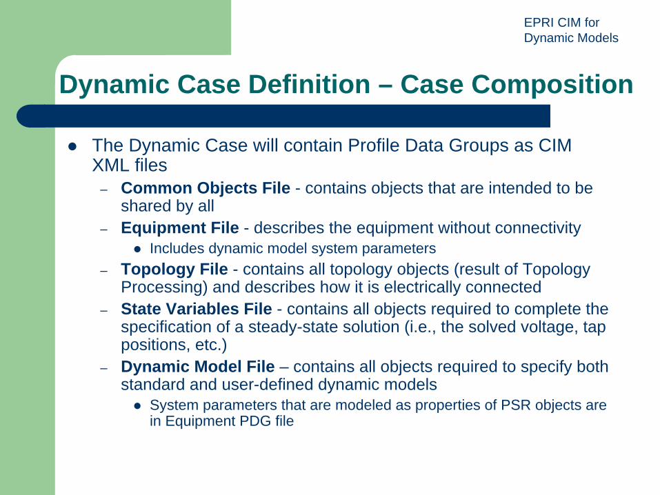
The Dynamic Case will contain Profile Data Groups as CIM XML files
– Common Objects File - contains objects that are intended to be shared by all
– Equipment File - describes the equipment without connectivityIncludes dynamic model system parameters
– Topology File - contains all topology objects (result of Topology Processing) and describes how it is electrically connected
– State Variables File - contains all objects required to complete the specification of a steady-state solution (i.e., the solved voltage, tap positions, etc.)
– Dynamic Model File – contains all objects required to specify both standard and user-defined dynamic models
System parameters that are modeled as properties of PSR objects are in Equipment PDG file

EPRI CIM for Dynamic Models
8
Standard Model Team
Lead: Bill Price, Consultant, GE PSLF expertMembers: 17 vendors, utilities, and NERCCharter: Develop the data requirements and mapping to the CIM for the exchange of standard models

EPRI CIM for Dynamic Models
9
Types of Dynamic Model Exchanges
Standard models– Includes multiple standard models (IEEE, WECC, etc.)
interconnected in a standard wayGenerators (including wind turbines)MotorsExcitation systems, limiters, and compensatorsTurbine/governor modelsStabilizersLoadsTransmission devicesRelay and protection devicesHVDC and FACTS
– GoalDefine standard model reference manual and list of standard modelsExtend CIM UML to model standard dynamic models and their interconnectionMinimize amount of information included in dynamic case file

EPRI CIM for Dynamic Models
10
Standard Model Team - Status
List of standard models – initial list complete– Models used by WECC, MMWG, UCTE – Corresponding models in IEEE, PSLF, PSS/E,
PowerFactory, EUROSTAG identifiedStandard Model Reference Manual
– EPRI published Summer 2009 IOP Version– Detailed descriptions of standard models
Standard interconnectionsBlock diagrams/equations, parameters, typical dataSample step responses being addedCIM class/attribute mapping in process
– More models to be addedPresent models sufficient for initial IOP
EPRI CIM for Dynamic Models
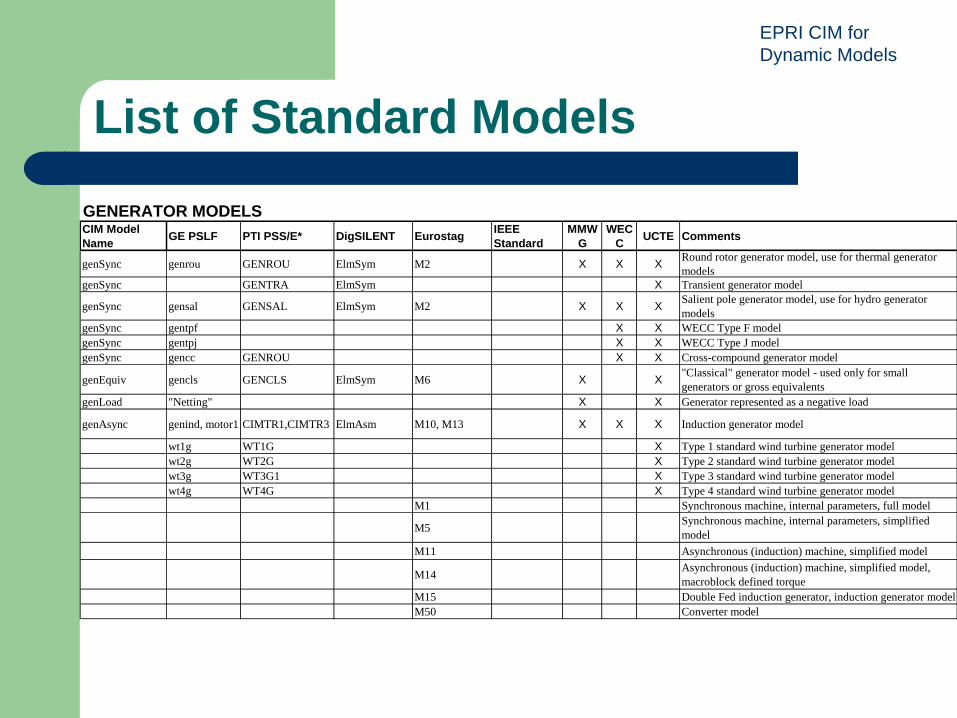
List of Standard Models
GENERATOR MODELSCIM Model Name GE PSLF PTI PSS/E* DigSILENT Eurostag IEEE
StandardMMW
GWEC
C UCTE Comments
genSync genrou GENROU ElmSym M2 X X X Round rotor generator model, use for thermal generator models
genSync GENTRA ElmSym X Transient generator model
genSync gensal GENSAL ElmSym M2 X X X Salient pole generator model, use for hydro generator models
genSync gentpf X X WECC Type F modelgenSync gentpj X X WECC Type J modelgenSync gencc GENROU X X Cross-compound generator model
genEquiv gencls GENCLS ElmSym M6 X X "Classical" generator model - used only for small generators or gross equivalents
genLoad "Netting" X X Generator represented as a negative load
genAsync genind, motor1 CIMTR1,CIMTR3 ElmAsm M10, M13 X X X Induction generator model
wt1g WT1G X Type 1 standard wind turbine generator modelwt2g WT2G X Type 2 standard wind turbine generator modelwt3g WT3G1 X Type 3 standard wind turbine generator modelwt4g WT4G X Type 4 standard wind turbine generator model
M1 Synchronous machine, internal parameters, full model
M5 Synchronous machine, internal parameters, simplified model
M11 Asynchronous (induction) machine, simplified model
M14 Asynchronous (induction) machine, simplified model, macroblock defined torque
M15 Double Fed induction generator, induction generator modelM50 Converter model

EPRI CIM for Dynamic Models
Standard Model Reference ManualSynchronous Generator Models For conventional power generating units (e.g., thermal, hydro, combustion turbine), a synchronous machine model represents the electrical characteristics of the generator and the mechanical characteristics of the turbine-generator rotational inertia. The standard interconnection variables between a synchronous generator model and other models are shown in the following figure and table:
Synchronous Generator Interconnection Variables
The interconnection with the electrical network equations may differ among application programs. The program only needs to know the terminal bus and generator ID to establish the correct interconnection.
Synchronous Generator Interconnection Variables
Model Type Synchronous Generator
Inputs: Name
Units Description Source
Efd p.u. Field voltage on base of Ifag * Rfd (field resistance) Exciter Pmech p.u. Mechanical shaft power to the generator Turbine
EPRI CIM for Dynamic Models
13
User-Defined Model Team
Lead: Chuck Dubose, Siemens PTI, PSSE expertMembers: 11 vendors, utilities, NERC, and UCTECharter: Develop list and definition of control blocks for user-defined models, and map dynamic case data to the CIM UML

EPRI CIM for Dynamic Models
14
Types of Dynamic Model Exchanges
User-Defined models– Includes
User-defined models (such as an exciter) comprising interconnected elementary control blocksUser-defined connectivity between control blocksVarious hybrid arrangements
– GoalProvide flexibility to completely specify a new model in a standard wayUse well-known elementary control blocks
– Ex: time delay, step function, log, sin, etc.
EPRI CIM for Dynamic Models
15
User-Defined Model Team - Status
List of elementary control blocks – List for IOP is complete
– Standard blocks defined to represent PTI PSSx BOSL, PowerFactory, EUROSTAG models
– Sufficient for application cases defined for IOPUser Defined Model Reference Manual
– Detailed descriptions of how to model user defined models using standard control blocks
Standard interconnection of control blocksBlock diagrams with equations, parametersThis information will also be stored in sending/receiving applicationsWill begin soon

EPRI CIM for Dynamic Models
16
List of Elementary Control BlocksBasic Control BlocksCIM Name
PTI PSS® x BOSL DIgSILENT EUROSTAG Usage Description
K PROP K gain y = K *x
This Block outputs the product of the input times a constant stored in the block. The Constant gain factor K is a parameter stored in the block and may be any floating point value. X is the input of the block and Y is the output of the block.
Integrater1 INT 1/sT lim limited integrator dy / dt = x / T
Add flags to indicate whther max and min limits will be used. Limits will be parameters of the blocks. x1 is the value of the minimum limit. x2 is the value of the maximum limit. x2 should be always larger than x1. integrator with non-windup limits.
Timelag1 DE1 1/(1+sT) simple lag first order time lag
Timelag2 DE2 limited simple lag
second order time lag. Non windup limits
LeadLag PD (1+sTa)/(1+sTb) lead lag filter y = x * Gain * [ (1+s*T) /
(1+s*T1) ] first order lead-lag with limits and gain

EPRI CIM for Dynamic Models
17
CIM Modeling Team
Lead: Kendall Demaree, Areva, CIM Model Manager for CIM User Group and IEC TC57Members: 7 vendors and consultantsCharter: Develop modeling approach to represent dynamic models and required signal connectivity in UML, building from existing CIM model
EPRI CIM for Dynamic Models
18
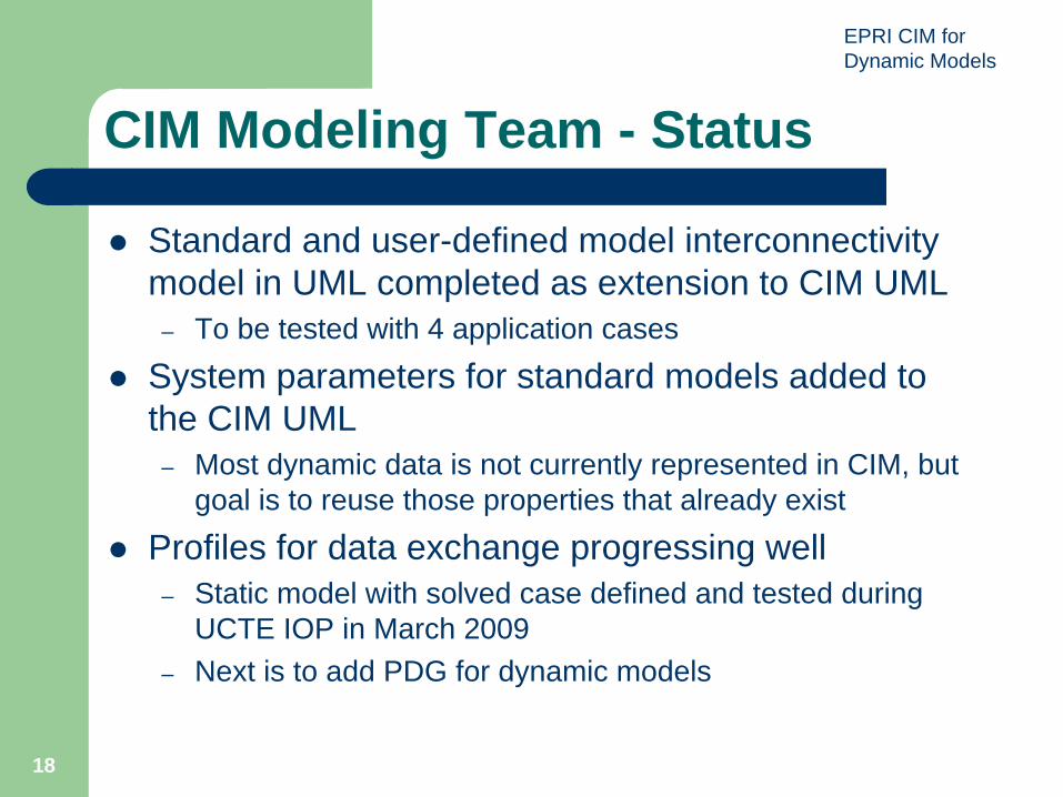
CIM Modeling Team - Status
Standard and user-defined model interconnectivity model in UML completed as extension to CIM UML
– To be tested with 4 application cases
System parameters for standard models added to the CIM UML
– Most dynamic data is not currently represented in CIM, but goal is to reuse those properties that already exist
Profiles for data exchange progressing well– Static model with solved case defined and tested during
UCTE IOP in March 2009– Next is to add PDG for dynamic models

EPRI CIM for Dynamic Models
1919
AC1 - Standard Model Example
Example: Synchronous Generating Unit

EPRI CIM for Dynamic Models
2020
AC2: User Defined Model Substitute for Standard Model
Synchronous Generating Unit

EPRI CIM for Dynamic Models
AC3 – Standard Models, User Defined Interconnection
Hydro Power Plant Connection Diagram:
Block4ElmPcu*
0
1
2
0
1
Block3ElmPcu*
0
1
2
0
1
Block2ElmPcu*
0
1
2
0
1
Block1ElmPcu*
0
1
2
0
1
HydraulikElmPmu*
0
1
2
3
4
5
6
7
0
1
2
3
4
5
Machine 4ElmSym*
Machine 3ElmSym*
Machine 2ElmSym*
Machine 1ElmSym*
Hydro Power Plant Connection Diagram:
huwhedr
speed4
speed3
speed2
speed1
pt4
pt3pt2pt1
qt4
qdv4
qt3
qdv3
qt2
qdv2
qt1
qdv1
DIg
SILE
NT

EPRI CIM for Dynamic Models
22
App Case 4 - Complete User Defined Model
EPRI CIM for Dynamic Models
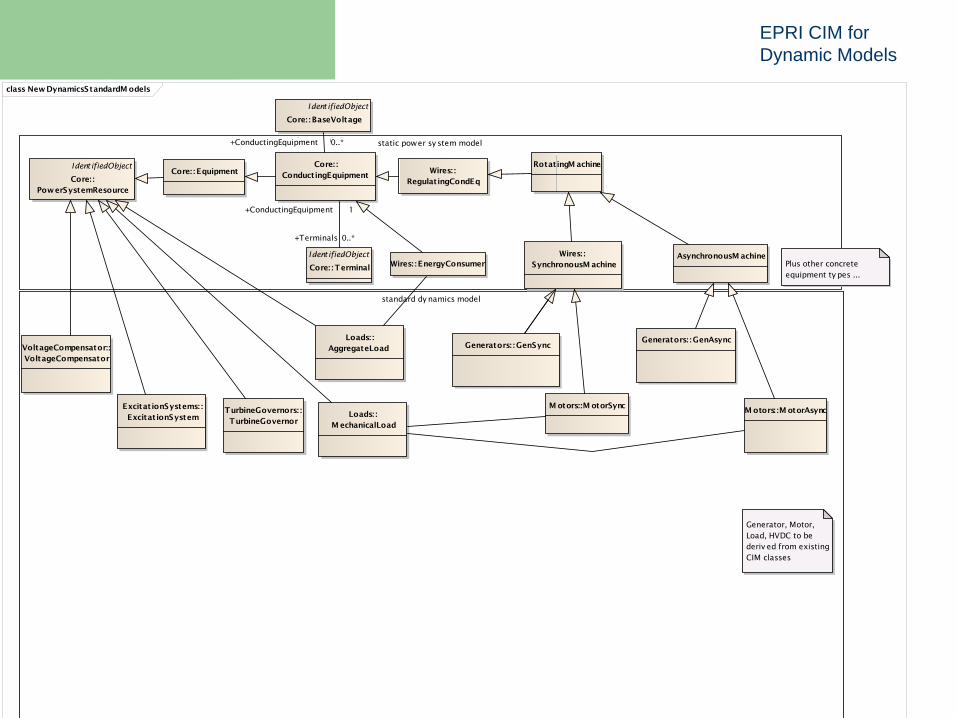
class NewDynamicsStandardM odels
static power sy stem model
standard dy namics model
Ident ifiedObject
Core: :PowerSystemResource
Core: : EquipmentCore: :
ConductingEquipment
Ident ifiedObject
Core: :Terminal
Wires: :SynchronousM achine
Wires: :RegulatingCondEq
Wires: : EnergyConsumer Plus other concrete equipment ty pes ...
Generator, Motor, Load, HVDC to be deriv ed from existing CIM classes
AsynchronousM achine
Ident ifiedObject
Core: : BaseVoltage
RotatingM achine
VoltageCompensator::VoltageCompensator
ExcitationSystems: :ExcitationSystem
TurbineGovernors: :TurbineGovernor
Loads: :AggregateLoad
Loads: :M echanicalLoad
M otors: :M otorAsyncM otors::M otorSync
Generators: :GenAsyncGenerators: : GenSync
+Terminals 0..*
+ConductingEquipment 1
+BaseVoltage 0..1+ConductingEquipment 0..*

EPRI CIM for Dynamic Models
class NewDynamicsUserdef inedM odel
static power sy stem model
instance dy namics model
meta dy namics model
Ident ifiedObject
M etaBlock
+ blockKind: BlockKind+ internal: Boolean+ primitiv e: Boolean
Ident ifiedObject
Core: :PowerSystemResource
Block
- inServ ice: int
Ident ifiedObject
BlockParameter
+ v alue: Float
BlockConnectable
M etaBlockParameter
Core: : EquipmentCore: :
ConductingEquipment
Ident ifiedObject
Core: :Terminal
Rotat ingMachine
Wires: :SynchronousM achine
Wires: :RegulatingCondEq
Wires: : EnergyConsumer
Plus other concrete equipment ty pes ...
Links to standard meta dy namic model names could be composed into BlockUsageParameter or BlockUsage object at UN-CFACT message assembly lev el.
IdentifiedObject
BlockConnectivity
Ident ifiedObject
M etaBlockOutputBlockConnectable
M etaBlockInput
Ident ifiedObject
M etaBlockRef erence
Ident ifiedObject
M etaBlockParameterRef erence
Ident ifiedObject
M etaBlockSignal
Ident ifiedObject
M etaBlockInputRef erence
Ident ifiedObject
M etaBlockOutputReference
Ident ifiedObject
M etaBlockConnectivity
0..*
0..10..*
0..10..*
0..1
0..*
0..1
1
metaBlockOutputReference
0..*
1
metaBlockInputReference
1
1 0..* 0..*1
0..*1
0..*
1
+Terminals 0..*
+ConductingEquipment 1
+BlockOutput
0..*
+Block
1
+BlockParameterReference
0..*
+BlockParameter
1
0..*
1
0..*1
0..*
0..1
0..*
1
0..*1
0..*
1
+MetaBlockParameter
0..*+MetaBlock1
0..*
1

EPRI CIM for Dynamic Models
25
Key Artifacts to be Produced
List and reference manual for standard dynamic models and control blocks for user-defined modelsExtensions to CIM UML information model to support dynamic case exchangesUML modeling approach to handle dynamic models with linkage to static load flow modelsTemplate for equipment suppliers to provide dynamic modelsNew exchange profiles for the various exchangesInteroperability test resultsPresentation and handover to IEC TC57
EPRI CIM for Dynamic Models
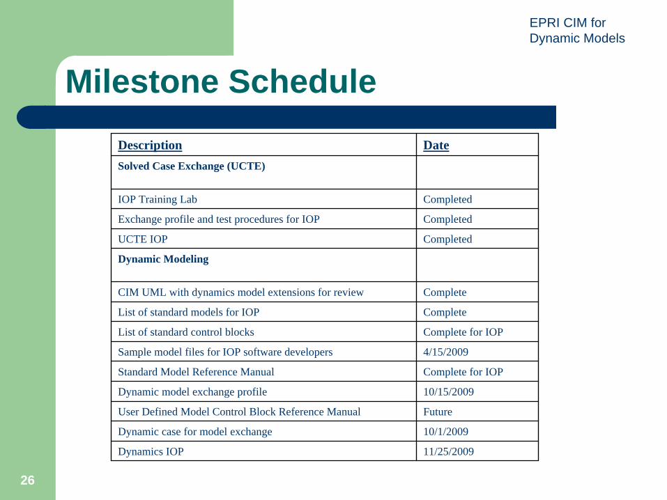
26
Milestone ScheduleDescription DateSolved Case Exchange (UCTE)
IOP Training Lab Completed
Exchange profile and test procedures for IOP Completed
UCTE IOP Completed
Dynamic Modeling
CIM UML with dynamics model extensions for review Complete
List of standard models for IOP Complete
List of standard control blocks Complete for IOP
Sample model files for IOP software developers 4/15/2009
Standard Model Reference Manual Complete for IOP
Dynamic model exchange profile 10/15/2009
User Defined Model Control Block Reference Manual Future
Dynamic case for model exchange 10/1/2009
Dynamics IOP 11/25/2009

EPRI CIM for Dynamic Models
Next Steps
IOP test for more complex user defined modelsFinal edition – Standard Model Reference ManualUser-Defined Model Reference ManualHVDC and FACTS modelsProprietary model exchange - testingRepository for dynamic model managementPromote use of new dynamic model standards by manufacturers and software vendors

EPRI CIM for Dynamic Models
2828
Standard Model UML Structure
EPRI CIM for Dynamic Models
2929
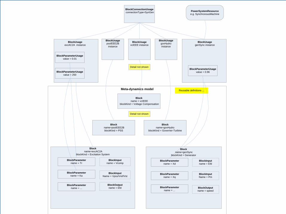
PowerSystemResourcee.g. SynchronousMachine
BlockParameterUsagevalue = 250
BlockParameterUsagevalue = 0.01
Meta-dynamics model
BlockUsageexcAC2A instance
BlockUsagepssIEEE2B
instance
BlockUsagegovHydro instance
Reusable definitions ...
Block name = vcIEEE
blockKind = Voltage Compensation
BlockInputname = Vcomp
BlockParametername = Tr
BlockOutputname = Efd
Blockname=excAC2A
blockKind = Excitation System
BlockInputName = Vpss/Vref/Vst
Block name=pssIEEE2B blockKind = PSS
Detail not shown
Blockname=govHydro
blockKind = Governer-Turbine
BlockUsagegenSync instance
BlockInputname = Efd
BlockParametername = Xd
BlockOutputname = speed
BlockInputName = Pm
BlockParametername = Xq
BlockParameterUsagevalue = 0.96
BlockParametername = Ka
BlockUsagevcIEEE instance
Detail not shown
BlockParametername = ... BlockParameter
name = ...
BlockConnectionUsageconnectionType=SynGen
Block name=genSync
blockKind = Generator