equ22-14 celldyn3200 op man
TRANSCRIPT

8/21/2019 Equ22-14 CellDyn3200 Op Man
http://slidepdf.com/reader/full/equ22-14-celldyn3200-op-man 1/690
CELL-DYN ® 3200 System Operator’s Manual i
9140181M—June 2004
Foreword
We welcome you to the role of Operator of the CELL-DYN 3200 System. Usingstate-of-the-art technology, we have designed your instrument to function
consistently and dependably on a day-to-day basis.
The CELL-DYN 3200 System is backed by dedicated professionals who excel in
engineering, training, and technical expertise. As you are a valued customer, we
will teach you how to operate, maintain, and troubleshoot your system.
For continuing service, we also provide telephone technical assistance should you
need additional information or assistance in diagnosing a problem. This service is
available 7 days a week, 24 hours a day in the United States.
If a problem should arise that cannot be resolved by telephone, on-site support is
offered by Abbott’s Field Service Representatives. Our Field Service
Representatives are extensively trained in all aspects of Abbott instrumentation,
which assures proficiency in diagnosing, isolating, and correcting problems.
Abbott Laboratories is dedicated to manufacturing the highest quality, most
reliable instrumentation available. We look forward to serving your needs in any
way possible.
Customer Support
United States: 1 (877) 4ABBOTT or 1 (877) 422-2688
Abbott Diagnostics Division
Customer Service:
200 Abbott Park Road
Abbott Park, IL 60064, U.S.A.
Canada: 1 (800) 387-8378
For customers outside the U.S., call your local Customer Service representative.
Intended Use
The CELL-DYN 3200 is a multiparameter hematology analyzer designed for in
vitro diagnostic use in clinical laboratories.
Proprietary Statement
The entire contents copyrighted 1995, 1998, 1999, 2001, 2003, and 2004 by Abbott
Laboratories. Abbott Laboratories’ software programs are protected by copyright.
All rights are reserved. The software was developed solely for use with Abbott
Laboratories equipment and for in vitro diagnostic applications as specified in the
operating instructions. No part of this media may be reproduced, stored, retrieved
or transmitted in any form or by any means without the prior written permission of
Abbott Laboratories.

8/21/2019 Equ22-14 CellDyn3200 Op Man
http://slidepdf.com/reader/full/equ22-14-celldyn3200-op-man 2/690
ii CELL-DYN ® 3200 System Operator’s Manual
9140181M—June 2004
Patent Statement
The following U.S. Patents are relevant to the CELL-DYN 3200 Instrument:
5,017,497; 5,378,633; 5,510,267; 5,733,784; and 5,958, 781.
Instrument Disclaimer All operating instructions must be followed. In no event shall Abbott be
responsible for failures, errors, or other liabilities resulting from a customer’s
noncompliance with the procedures and precautions outlined herein.
Pictorial Disclaimer
All samples (printouts, graphics, displays or screens, etc.) are for information and
illustration purposes only and shall not be used for clinical or maintenance
evaluations.
Abbott Instrument WarrantyAbbott Laboratories warrants CELL-DYN Instruments sold by Abbott Sales
Representatives (the “Instrument”) to be free from defects in workmanship and
materials during normal use by the original purchaser. This warranty shall continue
for a period of one (1) year, commencing twenty-one (21) days from date of
shipment to the original purchaser, or until title is transferred from the original
purchaser, whichever occurs first (the “Warranty Period”).
If any defects occur during the Warranty Period, contact Abbott Customer Service
immediately and be prepared to furnish pertinent details concerning the defect, the
Instrument model number, and the serial number.
Abbott’s Warranty coverage limits are as follows:
1. Abbott Customer Service: 24 hours per day, 7 days per week phone support
in the United States.
2. Field Service Representative support: 8:30 A.M. to 5:00 P.M. Monday through
Friday (excluding all Abbott-observed holidays).
3. Any on-site service performed at other times and all service required to
correct defects or malfunctions not covered by this Warranty (as noted in the
paragraph below) will be billed at Abbott’s labor rates then in effect.
This Warranty does not cover defects or malfunctions which:
1. Are not reported to Abbott during the Warranty Period and within one week
of occurrence.
2. Result from chemical decomposition or corrosion.
3. Are caused by customer or third party abuse, misuse, or negligence, or by
failure to comply with any requirement or instruction contained in the
applicable Abbott Operator’s Manual.
4. Result from maintenance, repair, or modification performed without Abbott’s
authorization.
8/21/2019 Equ22-14 CellDyn3200 Op Man
http://slidepdf.com/reader/full/equ22-14-celldyn3200-op-man 3/690
CELL-DYN ® 3200 System Operator’s Manual iii
9140181M—June 2004
Abbott’s liability for all matters arising from the supply, installation, use, repair,
and maintenance of the Instrument, whether arising under this Warranty or
otherwise, shall be limited solely to the repair or (at Abbott’s sole discretion)
replacement of the Instrument or of components thereof. In no event shall Abbott
be liable for injuries sustained by third parties, incidental or consequential
damages, or lost profits. Replaced parts shall become the property of AbbottLaboratories.
THE FOREGOING IS THE SOLE WARRANTY MADE BY ABBOTT
LABORATORIES REGARDING THE INSTRUMENT, AND ABBOTT
SPECIFICALLY DISCLAIMS ALL OTHER WARRANTIES, EXPRESSED OR
IMPLIED, INCLUDING THE IMPLIED WARRANTIES OF
MERCHANTABILITY AND OF FITNESS FOR A PARTICULAR PURPOSE.
The CELL-DYN 3200 Series Hematology Systems are manufactured by Abbott
Diagnostics Division, Abbott Laboratories, 200 Abbott Park Road, Abbott Park,
IL, 60064, USA. Please direct all inquiries concerning information in this manual
to the foregoing address.
Regulatory and Safety Agency Approvals
UL 61010A-1 Approved
CSA C22.2 No. 1010.1 Approved
IEC 1010-1 Approved
In Vitro Diagnostic Directive 98/79/EC
Legal Manufacturer Abbott Laboratories
Abbott Park, Il 60064, USA
Authorized Representative ABBOTT
Max-Planck-Ring 2
65205 Wiesbaden
Delkenheim, Germany

8/21/2019 Equ22-14 CellDyn3200 Op Man
http://slidepdf.com/reader/full/equ22-14-celldyn3200-op-man 4/690
iv CELL-DYN ® 3200 System Operator’s Manual
9140181M—June 2004
Trademark Statements
MAPSS is a trademark and CELL-DYN, CELL-DYN Hemcal, and Retic-RITE are
registered trademarks of Abbott Laboratories.
BJC, Canon, Epson, Hemogard, Microline, Millipore, Okidata, Sarstedt,
Technicon H·3, Teflon, Tygon, Vacutainer, Venoject II, and Westgard are nottrademarks of Abbott.
8/21/2019 Equ22-14 CellDyn3200 Op Man
http://slidepdf.com/reader/full/equ22-14-celldyn3200-op-man 5/690
CELL-DYN ® 3200 System Operator’s Manual v
9140181M—June 2004
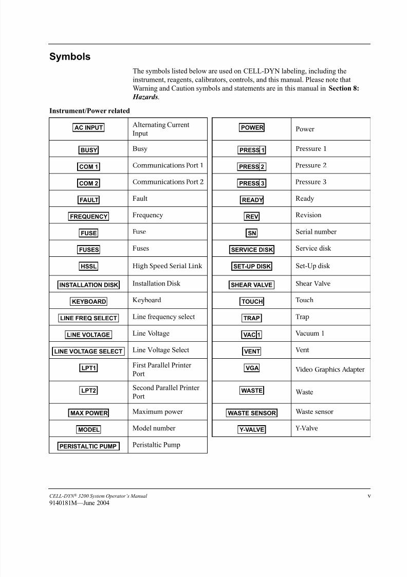
Symbols
The symbols listed below are used on CELL-DYN labeling, including the
instrument, reagents, calibrators, controls, and this manual. Please note that
Warning and Caution symbols and statements are in this manual in Section 8:
Hazards.
Instrument/Power related
Alternating Current
InputPower
Busy Pressure 1
Communications Port 1 Pressure 2
Communications Port 2 Pressure 3
Fault Ready
Frequency Revision
Fuse Serial number
Fuses Service disk
High Speed Serial Link Set-Up disk
Installation Disk Shear Valve
Keyboard Touch
Line frequency select Trap
Line Voltage Vacuum 1
Line Voltage Select Vent
First Parallel Printer
PortVideo Graphics Adapter
Second Parallel Printer
PortWaste
Maximum power Waste sensor
Model number Y-Valve
Peristaltic Pump
AC INPUT POWER
BUSY PRESS 1
COM 1 PRESS 2
COM 2 PRESS 3
FAULT READY
FREQUENCY REV
FUSE SN
FUSES SERVICE DISK
HSSL SET-UP DISK
INSTALLATION DISK SHEAR VALVE
KEYBOARD TOUCH
LINE FREQ SELECT TRAP
LINE VOLTAGE VAC 1
LINE VOLTAGE SELECT VENT
LPT1 VGA
LPT2 WASTE
MAX POWER WASTE SENSOR
MODEL Y-VALVE
PERISTALTIC PUMP

8/21/2019 Equ22-14 CellDyn3200 Op Man
http://slidepdf.com/reader/full/equ22-14-celldyn3200-op-man 6/690
vi CELL-DYN ® 3200 System Operator’s Manual
9140181M—June 2004
Reagent related
Cyanide-Free Hemoglobin/Nucleated Optical Count Lyse
Diluent
Diluent/Sheath
Enzymatic Cleaner Concentrate
Expiration Date
Hemoglobin
Hemoglobin Lyse
Lot Number
Red Blood Cell
Sheath
Storage temperature. (Example shows “Store at 2º–8ºC”)
White Blood Cell
White Blood Cell Lyse
Calibrator/Control related
Control Assay Disk
Whole Blood Calibrator
Whole Blood Control
Whole Blood Control, High
Whole Blood Control, Low
Whole Blood Control, Normal
CN-FREE HGB/NOC LYSE
DILUENT
DILUENT/SHEATH
ENZYMATIC CLEANER CONCENTRATE
HGB
HGB LYSE
LOT
RBC
SHEATH
8oC
2oC
8
2
WBC
WBC LYSE
CONTROL ASSAY DISK
WB CAL
WB CONTROL
WB CONTROL H
WB CONTROL L
WB CONTROL N

8/21/2019 Equ22-14 CellDyn3200 Op Man
http://slidepdf.com/reader/full/equ22-14-celldyn3200-op-man 7/690
CELL-DYN ® 3200 System Operator’s Manual vii
9140181K—July 2002
Miscellaneous
Authorized Representative
Consult instructions for use
Date of Manufacture
For In Vitro Diagnostic Use
Legal Manufacturer
List Number
EC REP
IVD
REF

8/21/2019 Equ22-14 CellDyn3200 Op Man
http://slidepdf.com/reader/full/equ22-14-celldyn3200-op-man 8/690
viii CELL-DYN ® 3200 System Operator’s Manual
9140181K—July 2002
Instrument Labeling
The following labels are affixed to the CELL-DYN 3200 System:
Current CELL-DYN customer’s instruments are CE Marked to the
European Electro-Magnetic Compliance (EMC) and Low-Voltage
Directives and have the following labels:
Laser Label, Front Panel
Laser Label, Rear Panel
Serial Number Label, Rear Panel
AVOID DIRECT EXPOSURE TO BEAM.
NICHT DIREKT IN DEN LASERSTRAHL BLICKEN.EVITER TOUTE EXPOSITION DIRECTE AU FAISCEAU LASER.
NO SE EXPONGA DIRECTAMENTE AL RAYO LASER.EVITARE OGNI ESPOSIZIONE DIRETTAAL RAGGIO.
LASER LIGHT WHEN OPEN.BEI OFFENER ABDECKUNG TRITT
LASERSTRAHLAUS.RAYON LASER SI OUVERT.
RADIACION LASER SI SE ABRE.LUCE LASER SE APERTO.
DANGER
GEFAHR DANGERPELIGRO PERICOLO
PN 9230701D
Class l Laser Product
per
lEC 825-1[1993]PN 9230702A
ABBOTT DIAGNOSTICS A wholly owned subsidiary of Abbott Laboratories
Abbott Park IL. 60064
THIS PRODUCT CONFORMS TOTHE APPLICABLE REQUIREMENTS
OF 21 CFR SUBCHAPTER J AT THE DATE OF MANUFACTURE
MANUFACTURED DATE
MODELNO.
SERIAL NO.
LIST NO. RE V

8/21/2019 Equ22-14 CellDyn3200 Op Man
http://slidepdf.com/reader/full/equ22-14-celldyn3200-op-man 9/690
CELL-DYN ® 3200 System Operator’s Manual ix
9140181K—July 2002
Voltage Label, Rear Panel
CE Label
Solution Container Label, Rear Panel
WARNING
WARNUNG
MISEEN GARDE
ADVERTENCIA
AVVERTENZA
: SET FOR 120 VOLTSWhen operation at other line voltage is required, refer to operation manual for detailed instructions.
: FUER 120 VOLT EINGESTELLTIst der Betrieb mit einer anderen Netzspannung erforderlich, entnehmen Sie die genauen
Anweisungen der Bedienungsanleitung.: PARAMETRE POUR UTILISATION SUR 120 VOLTS
Si une utilisation à une tension de réseau différente est requise, reportez-vous au ManuelTechnique pour de plus amples informations.
: CONFIGURADO PARA 120 VOLTIOS
Si se necesita otra tensión diferente a la indicada, consulte el Manual de Operaciones parainstrucciones más detalladas.
: CONFIGURATO PER 120 VOLTSe la tensione è di voltaggio diverso, fare riferimento alle istruzioni dettagliate nel Manuale diImpiego. PN 9230003
CAUTION: DO NOT HANDLE
SOLUTION CONTAINER
UNLESS PROPERLY
PROTECTED. REFER TO
OPERATOR’S MANUAL FOR
INSTALLATION PROCEDURE.
PN 9230334

8/21/2019 Equ22-14 CellDyn3200 Op Man
http://slidepdf.com/reader/full/equ22-14-celldyn3200-op-man 10/690
x CELL-DYN ® 3200 System Operator’s Manual
9140181L—July 2003
New CELL-DYN customer’s instruments are CE Marked to the European In Vitro
Diagnostic Directive, which encompasses the requirements of the EMC and Safety
Directives, and have the following labels:
Laser Label, Front Panel
Laser Label, Rear Panel
Serial Number Label, Rear Panel
CAUTION –
CLASS 3B LASER LIGHT WHEN OPEN.
AVOID EXPOSURE TO BEAM.
PN 923 7 1
PN 9230702C
CLASS 1 LASER PRODUCT/Lasergert der Klasse 1/Produit laser de classe 1/Lser declase 1/Prodotto laser di classe 1/Produto laser da classe 1/Klasse 1-laserprodukt/Klass 1 laserprodukt/Προϊόν λέιζερ κλάσης 1
ABBOTT DIAGNOSTICS DIVISIONAbbott Laboratories
Abbott Park IL, 60064 USATHIS PRODUCT CONFORMS TO
THE APPLICABLE REQUIREMENTSOF 21 CFR SUBCHAPTER J AT THE DATE
OF MANUFACTURE
DATE OF MANUFACTURE
MADE IN U.S.A. PN 9230308 REV G

8/21/2019 Equ22-14 CellDyn3200 Op Man
http://slidepdf.com/reader/full/equ22-14-celldyn3200-op-man 11/690
CELL-DYN ® 3200 System Operator’s Manual xi
9140181M—June 2004
Biological Risk Label
CE Mark Label, Rear Panel
Voltage Label, Rear Panel
Solution Container Label, Rear Panel
ABBOTTMax-Planck-Ring 265205 WiesbadenGermany+49-6122-580
ABBOTT LABORATORIESAbbott Park, IL 60064 USA
PN 9230751
PN 9230003F
WARNING: SET FOR 120 VOLTS / ACHTUNG: FR 120 VOLT EINGESTELLT /
ADVARSEL: KONFIGURERET TIL 120 V / VARNING: INSTLLD FR 120 VOLT /
Consult instructions for use if different voltage is required. / Ist der Betrieb mit einer anderenNetzspannung erforderlich, in der Bedienungsanleitung nachlesen. / Si une utilisation unetension diffrente est requise, consulter les instructions d’utilisation. / Consulte las instrucciones deuso si la tensin es distinta. / Per un voltaggio diverso, consultare le istruzioni per l’uso. /Se for necessria uma voltagem diferente, consultar as instrues de utilizao. /Se brugermanualen, hvis der er behov for drift med en anden netspnding. / Ls tillhrandedokumentation om en annan spnning behvs. / Για χρήση σε άλλη τάση ρεύµατος,συµβουλευτείτε τις οδηγίες χρήσης.
ΠΡΟΕΙ∆ΟΠΟΙΗΣΗ:ΧΡΗΣΗ ΣΤΑ 120 VOLTS
MISE EN GARDE : UTILISATION A 120 VOLTS / ADVERTENCIA: 120 VOLTIOS /
AVVERTENZA: CONFIGURATO A 120 VOLT / AVISO: CONFIGURADO PARA 120 VOLTS /
PN 9230334E
Consult instructions for use. / Siehe Packungsbeilage. / Consulter les instructionsd’utilisation. / Consulte las instrucciones de uso. / Consultare le istruzioni per l’uso. /Consultar as instrues de utilizao. / Se brugsanvisningen. / Ls tillhrandedokumentation. / Συµβουλευτείτε τις οδηγίες χρήσης. / Viz návod k použití.
CAUTION: Do not handle Solution Container unless properly protected.VORSICHT: Die Reagenzbehlter nur ordnungsgem gesichert bewegen.ATTENTION : Ne pas manipuler le flacon de solution sans protectionapproprie.
PRECAUCIN: no maneje el recipiente de la solucin a menos que est protegido adecuadamente.ATTENZIONE: Non maneggiare il recipiente della soluzione se non si protetti in modo adeguato.ATENO: no manipular o recipiente da soluo sem estar devidamente protegido.VIGTIGT: Beholderen med oplsning m ikke hndteres, medmindre brugeren er korrekt beskyttet.VIKTIGT: Anvnd skyddsklder vid hantering av lsningsbehllarna.ΠΡΟΣΟΧΗ:Χρησιµοποιείτε το ∆οχείο Ρυθµιστικού διαλύµατος µόνο αφού λάβετε τιςκατάλληλες προφυλάξεις.UPOZORNĚNÍ:Nemanipulujte s nádobou obsahuj ící roztok, pokud není řádně zabezpečena.

8/21/2019 Equ22-14 CellDyn3200 Op Man
http://slidepdf.com/reader/full/equ22-14-celldyn3200-op-man 12/690
xii CELL-DYN ® 3200 System Operator’s Manual
9140181K—July 2002
NOTES

8/21/2019 Equ22-14 CellDyn3200 Op Man
http://slidepdf.com/reader/full/equ22-14-celldyn3200-op-man 13/690
CELL-DYN ® 3200 System Operator’s Manual xiii
9140181L—July 2003
How to Use This Manual
Overview
This Operator’s Manual contains complete instructions for using and maintaining
the CELL-DYN 3200 System.
This manual was designed to fill several needs, from providing step-by-step
operating instructions to listing accessory part numbers. You will find it a valuable
aid as you learn to use the system and an essential reference thereafter.
A basic principle of effective learning is to proceed from the general to the specific.
That is the way the material in this manual is presented. And that is how we wish
to present the manual to you.
The first and most important step is to get acquainted with the Master Table of
Contents. For this reason, we start with a brief overview to show you how the
information is organized in sections.
After that, we explain how the manual is physically designed to help you locate
desired information quickly and easily.
Finally, we discuss different ways material is presented for different purposes and
explain various icons that identify specialized types of information in the text.
Please take the time to read and understand this brief preparatory section.
Manual Organization
Front Matter
The pages in front of the Master Table of Contents contain two main sections: A
Foreword that includes customer service and intended use information, and How
to Use This Manual that includes a description of the organization. These pagesalso contain proprietary, warranty, trademark statements, and Manual Revision and
Status Logs.
Section 1. Use or Function
This section provides an overall description of the system and its components. It
names the major system components and tells what they are used for.
Section 2. Installation Procedures and Special Requirements
This section provides instructions for installing the CELL-DYN 3200 system. It
explains proper location, installation, setup, and configuration to meet your
laboratory’s specific needs.
Section 3. Principles of Operation
This section explains the principles behind the system’s operation. It describes
what the system measures and how those measurements are made. It also explains
the translation of those measurements into useful data and reports for the user.
8/21/2019 Equ22-14 CellDyn3200 Op Man
http://slidepdf.com/reader/full/equ22-14-celldyn3200-op-man 14/690
xiv CELL-DYN ® 3200 System Operator’s Manual
9140181K—July 2002
Section 4. Performance Characteristics and Specifications
This section contains useful details on the dimensions of the instrument, proper
operating environment, and performance specifications.
Section 5. Operating Instructions
This section contains detailed instructions to set up the instrument and explains the procedures for daily start-up and shutdown, sample collection and handling,
routine operation of the instrument, sample analysis, and use of the data log.
Section 6. Calibration Procedures
This section takes you step by step through the calibration process. It discusses
calibration materials, guidelines, and methods, including troubleshooting
procedures and corrective action.
Section 7. Operational Precautions and Limitations
This section contains a summary of known factors that may adversely affect the
proper operation of the instrument or the quality of the output.
Section 8. Hazards
This section covers possible hazards arising from the operation of the instrument,
as well as decontamination and waste handling procedures.
Section 9. Service and Maintenance
This section discusses routine maintenance and cleaning on a daily, weekly,
monthly, and “as needed” basis. Also included are detailed instructions for
removing, cleaning, and replacing various components to ensure proper system
performance.
Section 10. Troubleshooting and DiagnosticsThis section discusses the diagnostics capability of the instrument. It contains a
troubleshooting guide to help users identify probable causes of a system
malfunction or of suspect data, and to suggest the proper corrective action.
Section 11. Quality Control
This section covers the proper mixing, handling, and running of control material,
setting up QC files and using the QC capabilities of the instrument, and setting up
and using the X-B Analysis Program. It also provides a review of the Westgard®
Rules.
Section 12. PrintersThis section reviews the setup and use of printers for graphics output and ticket
printing.
Section 13. Sample Loader
This section includes material from all the previous sections which pertains
specifically to the installation, operation, and maintenance of the Sample Loader.

8/21/2019 Equ22-14 CellDyn3200 Op Man
http://slidepdf.com/reader/full/equ22-14-celldyn3200-op-man 15/690
CELL-DYN ® 3200 System Operator’s Manual xv
9140181K—July 2002
Section 14. Reticulocyte Package
This section contains detailed information on how to turn ON the reticulocyte
package, set up retic QC and retic patient limits, and prepare and process retic
samples.
Appendices Appendix A describes how to use bar codes on the CELL-DYN 3200 and contains
information on bar code types and bar code labels.
Appendix B lists the part numbers of components, accessories, controls, reagents,
and consumables associated with the CELL-DYN 3200 System for user
convenience when placing orders.
Index
This section contains an alphabetical listing of subject matter to help users quickly
locate specific information about the system.
Manual ConstructionThe physical construction of the manual supports its sectional organization.
Master Table of Contents
The Master Table of Contents at the beginning of this manual lists each section and
its subsections.
Section Separators
A large separator tab marks the start of each section.

8/21/2019 Equ22-14 CellDyn3200 Op Man
http://slidepdf.com/reader/full/equ22-14-celldyn3200-op-man 16/690
xvi CELL-DYN ® 3200 System Operator’s Manual
9140181K—July 2002
Text Conventions Used in This Manual
The following list summarizes the text conventions that are used in this manual:
Soft Keys (Screen Label Keys)
Screen labels are menu keys displayed at the bottom of the display screen. Directly
below the display screen is a row of eight unlabeled pressure-sensitive keys which
correspond to the menu labels. Pressing one of these keys (on the membranekeypad) initiates the action specified by the corresponding menu label.
This manual indicates that one of these “soft keys” is to be pressed by showing the
label in all caps, bold, sans serif font, and enclosed in brackets. For example, when
the manual calls for the operator to press the key under the RUN label and then the
key under the SPECIMEN TYPE label, the text will read “Press [RUN] followed by
[SPECIMEN TYPE].”
Keyboard/Keypad Keys
In some cases, the operator must press a key on the PC keyboard or on the pressure-
sensitive keypad on the front of the instrument. Such keys include the Enter key,
the ESC key, the pound (#) key, and other special function keys. Special function
keys, such as the arrow keys, are in regular type. The arrow symbol may be
substituted for the word. For example, the text will read “Press the arrow keys” or
“Press the ↑ key” or “Press the ↑ arrow key.”
The Print Screen key on the keyboard can be used to print the screen as it is
displayed on the monitor. This allows the operator an option to print the screen
when the [PRINT] soft key is not available.
Information Presentation Examples
Menu name Sans serif font, all capital letters MAIN MENUDATA LOG menu
Soft keys (screen label keys) Sans serif font, all capital letters,enclosed in brackets
[RUN]
Keyboard/keypad keys Regular font, initial capital letters onlywhen appropriate
arrow keys↑ arrow keyEnter keyESC keyPage Up keythe pound (#) keythe asterisk (*) key
Status Regular font, all capital letters READY
STANDBYINITIALIZED
Data entry field Regular font, enclosed in angle brackets <Operator ID> field
Screen message or other screendisplay
Courier Waste Full
ON and OFF All caps, regular font ONOFF

8/21/2019 Equ22-14 CellDyn3200 Op Man
http://slidepdf.com/reader/full/equ22-14-celldyn3200-op-man 17/690
CELL-DYN ® 3200 System Operator’s Manual xvii
9140181K—July 2002
NOTE: Press the Print Screen Key only when the displayed screen is at a
static state. Pressing the key during an instrument action, i.e., run
cycle may not print the screen properly.
Safety
Operation, maintenance and servicing of hematology systems may expose
individuals to potential safety and health hazards. All work must be
performed as described in the CELL-DYN Operator’s manual or as
directed by an Abbott Representative. For detailed safety information,
refer to Section 8: Hazards.
Warnings are inserted throughout this manual to alert personnel to
potential hazards. The standard warning conventions including signal
words and symbols are described in Section 8: Hazards.

8/21/2019 Equ22-14 CellDyn3200 Op Man
http://slidepdf.com/reader/full/equ22-14-celldyn3200-op-man 18/690
xviii CELL-DYN ® 3200 System Operator’s Manual
9140181K—July 2002
Revision Status
Document Control
Number(s)
Revision
Date
Section(s)
Revised
Pages Revised
and Added
9140181H 10/01 All All
9340541B N/A All (new tabset) N/A
9140181J 3/02 Forward All
How To Use This
Manual
All
Master Table of
Contents
pp. 1 through 5; 12 through 14; 19
List of Figures p. 3
1: Use or Function pp. 1-1 and 1-2; 1-8; 1-18 and 1-19
2: InstallationProcedures and
Special
Requirements
pp. 2-3; 2-7; 2-15
3: Principles of
Operation
p. 3-7
4: Performance
Characteristics and
Specifications
pp. 4-4 and 4-5
5: Operating
Instructions
pp. 5-8; 5-10; 5-99
6: Calibration pp. 6-21; 6-26; 6-30 through 6-32; 6-57
7: Operational
Precautions and
Limitations
pp. 7-1 and 7-2
8: Hazards All
9: Service and
Maintenance
pp. 9-12; 9-55 and 9-56
13: Sample Loader p. 13-1
Appendix B pp. B-1; B-3
Index All

8/21/2019 Equ22-14 CellDyn3200 Op Man
http://slidepdf.com/reader/full/equ22-14-celldyn3200-op-man 19/690
CELL-DYN ® 3200 System Operator’s Manual xix
9140181K—July 2002
NOTE: For existing customers, pages of 9140181J will be changed to Revision K and sent with 9140181K
9140181K 7/02 Forward All
How To Use This
Manual
All
Master Table of
Contents
pp. 1 through 5; 10; 12 through 20
List of Figures pp. 3 and 4
List of Tables All
1: Use or Function pp. 1-1 and 1-2; 1-8; 1-16; 1-18 and 1-19
2: Installation
Procedures and
SpecialRequirements
pp. 2-3; 2-5; 2-7; 2-15
3: Principles of
Operation
pp. 3-7; 3-16; 3-28; 3-31 through 3-36
4: Performance
Characteristics and
Specifications
pp. 4-4 and 4-5
5: Operating
Instructions
pp. 5-8; 5-10; 5-42 through 5-44; 5-86 and
5-87; 5-99; 5-128
6: Calibration pp. 6-21; 6-26; 6-30 through 6-32; 6-57
7: OperationalPrecautions and
Limitations
pp. 7-1 and 7-2
8: Hazards All
9: Service and
Maintenance
pp. 9-12; 9-21; 9-25; 9-46; 9-55 and 9-56;
9-59; 9-61
10: Troubleshooting
and Diagnostics
pp. 10-24 and 10-25; 10-28 and
10-29; 10-65; 10-89
11: Quality Control p. 11-17
13: Sample Loader p. 13-114: Reticulocyte
Package
pp. 14-20; 14-47; 14-61; 14-68 through
14-69
Appendix B pp. B-1; B-3
Index All
Document Control
Number(s)
Revision
Date
Section(s)
Revised
Pages Revised
and Added
8/21/2019 Equ22-14 CellDyn3200 Op Man
http://slidepdf.com/reader/full/equ22-14-celldyn3200-op-man 20/690
xx CELL-DYN ® 3200 System Operator’s Manual
9140181K—July 2002
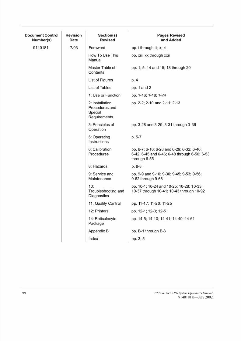
9140181L 7/03 Foreword pp. i through iii; x; xi
How To Use This
Manual
pp. xiii; xx through xxii
Master Table of
Contents
pp. 1; 5; 14 and 15; 18 through 20
List of Figures p. 4
List of Tables pp. 1 and 2
1: Use or Function pp. 1-16; 1-18; 1-24
2: Installation
Procedures and
Special
Requirements
pp. 2-2; 2-10 and 2-11; 2-13
3: Principles of
Operation
pp. 3-28 and 3-29; 3-31 through 3-36
5: Operating
Instructions
p. 5-7
6: Calibration
Procedures
pp. 6-7; 6-10; 6-28 and 6-29; 6-32; 6-40;
6-42; 6-45 and 6-46; 6-48 through 6-50; 6-53
through 6-55
8: Hazards p. 8-8
9: Service and
Maintenance
pp. 9-9 and 9-10; 9-30; 9-45; 9-53; 9-56;
9-62 through 9-66
10:
Troubleshooting and
Diagnostics
pp. 10-1; 10-24 and 10-25; 10-28; 10-33;
10-37 through 10-41; 10-43 through 10-92
11: Quality Control pp. 11-17; 11-20; 11-25
12: Printers pp. 12-1; 12-3; 12-5
14: Reticulocyte
Package
pp. 14-5; 14-10; 14-41; 14-49; 14-61
Appendix B pp. B-1 through B-3
Index pp. 3; 5
Document Control
Number(s)
Revision
Date
Section(s)
Revised
Pages Revised
and Added

8/21/2019 Equ22-14 CellDyn3200 Op Man
http://slidepdf.com/reader/full/equ22-14-celldyn3200-op-man 21/690
CELL-DYN ® 3200 System Operator’s Manual xxi
9140181M—June 2004
9140181M 06/04 Foreword pp. i through vi; xi
How To Use This
Manual
pp. xxi through xxiv
Master Table of
Contents
pp. 1 and 2; 5 through 11; 14 through 16; 19
and 20
List of Tables pp. 1 and 2
1: Use or Function pp. 1-1 and 1-2; 1-8; 1-16; 1-27
2: Installation
Procedures and
Special Requirements
pp. 2-3; 2-5 through 2-7; 2-10 and 2-11; 2-15
3: Principles of
Operation
pp. 3-23; 3-28 through 3-40
4: Performance
Characteristics
pp. 4-1; 4-12
5: Operating
Instructions
pp. 5-16 and 5-17; 5-28; 5-46; 5-83 and 5-84;
5-86; 5-105 through 5-108; 5-116; 5-118
through 5-123; 5-127 through 5-129
6: Calibration
Procedures
pp. 6-3; 6-5; 6-8; 6-19 and 6-20; 6-26 through
6-32; 6-37; 6-42 through 6-46; 6-48 and 6-49;
6-53 through 6-55
8: Hazards pp. 8-7 and 8-8
9: Service andMaintenance
pp. 9-9; 9-11; 9-17; 9-19 through 9-22; 9-24;9-30 through 9-33; 9-37; 9-40; 9-51 and 9-52;
9-54
10: Troubleshooting
and Diagnostics
pp. 10-24; 10-64 through 10-67; 10-69; 10-71;
10-73 through 10-80
11: Quality Control pp. 11-18; 11-22
12: Printers p. 12-1
13: Sample Loader p. 13-1
14: Reticulocyte
Package
pp. 14-27; 14-29; 14-60; 14-65 and 14-66;
14-69 through 14-72
Appendix A p. A-6
Appendix B pp. B-1 through B-4
Appendix C pp. C-1 and C-2
Index pp. 1 through 3; 5 through 8
Document Control
Number(s)
Revision
Date
Section(s)
Revised
Pages Revised
and Added

8/21/2019 Equ22-14 CellDyn3200 Op Man
http://slidepdf.com/reader/full/equ22-14-celldyn3200-op-man 22/690
xxii CELL-DYN ® 3200 System Operator’s Manual
9140181M—June 2004
Revision Log
Instructions: Use this log to provide a permanent record to verify
that revised chapter(s) and/or page(s) have been added to this
manual.
1. Record the document control number of the revised section in the first
column. You will find the number in the footer. Make an entry for each
chapter you receive and place in the manual.
2. Record the revision date, also found in the footer, in the second column.
3. Record the current CELL-DYN 3200 System software version in the third
column.
4. Write your initials or signature in the fourth column to verify that you have
placed the revised page(s) in the manual.
5. Record the date that you added the revised section to the manual in the fifth
column.
Document
Control Number
Revision
DateSoftware Version
Revision
Incorporated by
Date
Incorporated

8/21/2019 Equ22-14 CellDyn3200 Op Man
http://slidepdf.com/reader/full/equ22-14-celldyn3200-op-man 23/690
CELL-DYN ® 3200 System Operator’s Manual xxiii
9140181M—June 2004
Conclusion
We hope you have found this preview of the manual useful. The information in this
section should help you better understand the construction and organization of this
manual and help you get started easily and quickly.

8/21/2019 Equ22-14 CellDyn3200 Op Man
http://slidepdf.com/reader/full/equ22-14-celldyn3200-op-man 24/690
xxiv CELL-DYN ® 3200 System Operator’s Manual
9140181M—June 2004
NOTES

8/21/2019 Equ22-14 CellDyn3200 Op Man
http://slidepdf.com/reader/full/equ22-14-celldyn3200-op-man 25/690
CELL-DYN ® 3200 System Operator’s Manual Master Table of Contents-1
9140181M—June 2004
Master Table of Contents
Master Table of Contents
Foreword . . . . . . . . . . . . . . . . . . . . . . . . . . . . . . . . . . . . . . . . . . . . . . . . . . . . . . . . . . . . . . . . . . . . . . i
Customer Support . . . . . . . . . . . . . . . . . . . . . . . . . . . . . . . . . . . . . . . . . i
Intended Use . . . . . . . . . . . . . . . . . . . . . . . . . . . . . . . . . . . . . . . . . . . . . i
Proprietary Statement . . . . . . . . . . . . . . . . . . . . . . . . . . . . . . . . . . . . . . i
Patent Statement . . . . . . . . . . . . . . . . . . . . . . . . . . . . . . . . . . . . . . . . . . ii
Instrument Disclaimer. . . . . . . . . . . . . . . . . . . . . . . . . . . . . . . . . . . . . . ii
Pictorial Disclaimer . . . . . . . . . . . . . . . . . . . . . . . . . . . . . . . . . . . . . . . ii
Abbott Instrument Warranty. . . . . . . . . . . . . . . . . . . . . . . . . . . . . . . . . ii
Regulatory and Safety Agency Approvals . . . . . . . . . . . . . . . . . . . . . iii
Trademark Statements . . . . . . . . . . . . . . . . . . . . . . . . . . . . . . . . . . . . iv
Symbols . . . . . . . . . . . . . . . . . . . . . . . . . . . . . . . . . . . . . . . . . . . . . . . . v
Instrument Labeling . . . . . . . . . . . . . . . . . . . . . . . . . . . . . . . . . . . . . viii
How to Use This Manual . . . . . . . . . . . . . . . . . . . . . . . . . . . . . . . . . xiii
Overview. . . . . . . . . . . . . . . . . . . . . . . . . . . . . . . . . . . . . . . . . . . xiii
Manual Organization . . . . . . . . . . . . . . . . . . . . . . . . . . . . . . . . . xiii
Manual Construction. . . . . . . . . . . . . . . . . . . . . . . . . . . . . . . . . . . xv
Text Conventions Used in This Manual . . . . . . . . . . . . . . . . . . . . . . xvi
Soft Keys (Screen Label Keys). . . . . . . . . . . . . . . . . . . . . . . . . . xvi
Keyboard/Keypad Keys . . . . . . . . . . . . . . . . . . . . . . . . . . . . . . . xvi
Safety . . . . . . . . . . . . . . . . . . . . . . . . . . . . . . . . . . . . . . . . . . . . . . . . xvii
Revision Status . . . . . . . . . . . . . . . . . . . . . . . . . . . . . . . . . . . . . . . . xviii
Revision Log. . . . . . . . . . . . . . . . . . . . . . . . . . . . . . . . . . . . . . . . . . . xxii
Conclusion . . . . . . . . . . . . . . . . . . . . . . . . . . . . . . . . . . . . . . . . . . . xxiii
Use or Function . . . . . . . . . . . . . . . . . . . . . . . . . . . . . . . . . . . . . . . . . . . . . . . . . . . . . . . . . . . . . . 1-1
Overview. . . . . . . . . . . . . . . . . . . . . . . . . . . . . . . . . . . . . . . . . . . . . . . . . . . . 1-1
Intended Use . . . . . . . . . . . . . . . . . . . . . . . . . . . . . . . . . . . . . . . . . . . 1-2
System Components . . . . . . . . . . . . . . . . . . . . . . . . . . . . . . . . . . . . . . . . . . . 1-5
Analyzer Components. . . . . . . . . . . . . . . . . . . . . . . . . . . . . . . . . . . . 1-6
Front Panel . . . . . . . . . . . . . . . . . . . . . . . . . . . . . . . . . . . . . . . . . 1-6
Flow Panel . . . . . . . . . . . . . . . . . . . . . . . . . . . . . . . . . . . . . . . . . 1-6Left Side Panel . . . . . . . . . . . . . . . . . . . . . . . . . . . . . . . . . . . . . . 1-6
Right Side Panel . . . . . . . . . . . . . . . . . . . . . . . . . . . . . . . . . . . . . 1-6
Rear Panel . . . . . . . . . . . . . . . . . . . . . . . . . . . . . . . . . . . . . . . . . . 1-7
Component Description . . . . . . . . . . . . . . . . . . . . . . . . . . . . . . . . . . 1-8
Front Panel . . . . . . . . . . . . . . . . . . . . . . . . . . . . . . . . . . . . . . . . . 1-8
Left Front Cover . . . . . . . . . . . . . . . . . . . . . . . . . . . . . . . . . . . . . 1-8
Right Front Cover . . . . . . . . . . . . . . . . . . . . . . . . . . . . . . . . . . . . 1-8

8/21/2019 Equ22-14 CellDyn3200 Op Man
http://slidepdf.com/reader/full/equ22-14-celldyn3200-op-man 26/690
Master Table of Contents-2 CELL-DYN ® 3200 System Operator’s Manual
9140181M—June 2004
Master Table of Contents
Front Skirt Cover . . . . . . . . . . . . . . . . . . . . . . . . . . . . . . . . . . . . 1-9
Status Indicator Panel . . . . . . . . . . . . . . . . . . . . . . . . . . . . . . . . . 1-9
(Open Sample) Aspiration Probe . . . . . . . . . . . . . . . . . . . . . . . . 1-9
Touch Plate . . . . . . . . . . . . . . . . . . . . . . . . . . . . . . . . . . . . . . . . . 1-9
Sample Loader . . . . . . . . . . . . . . . . . . . . . . . . . . . . . . . . . . . . . . 1-9
(Closed Sample) Tower Cover . . . . . . . . . . . . . . . . . . . . . . . . . . 1-9
Flow Panel . . . . . . . . . . . . . . . . . . . . . . . . . . . . . . . . . . . . . . . . . . . 1-10
Shear Valve Assembly . . . . . . . . . . . . . . . . . . . . . . . . . . . . . . . 1-10
Syringe Assembly. . . . . . . . . . . . . . . . . . . . . . . . . . . . . . . . . . . 1-11
Sample Transfer Peristaltic Pump. . . . . . . . . . . . . . . . . . . . . . . 1-11
HGB Flow Cell and Mixing Chamber . . . . . . . . . . . . . . . . . . . 1-11
WBC Mixing Chamber. . . . . . . . . . . . . . . . . . . . . . . . . . . . . . . 1-11
RBC/PLT Mixing Chamber . . . . . . . . . . . . . . . . . . . . . . . . . . . 1-11
Wash Block. . . . . . . . . . . . . . . . . . . . . . . . . . . . . . . . . . . . . . . . 1-11
Normally Closed Valves. . . . . . . . . . . . . . . . . . . . . . . . . . . . . . 1-12
Diluent Reservoir . . . . . . . . . . . . . . . . . . . . . . . . . . . . . . . . . . . 1-12Sheath Reservoir . . . . . . . . . . . . . . . . . . . . . . . . . . . . . . . . . . . . 1-12
Waste Chambers . . . . . . . . . . . . . . . . . . . . . . . . . . . . . . . . . . . . 1-12
Bubble Traps. . . . . . . . . . . . . . . . . . . . . . . . . . . . . . . . . . . . . . . 1-12
Aerosol Filter . . . . . . . . . . . . . . . . . . . . . . . . . . . . . . . . . . . . . . 1-12
Pinch Valves . . . . . . . . . . . . . . . . . . . . . . . . . . . . . . . . . . . . . . . 1-12
Closed Mode Aspiration Tower . . . . . . . . . . . . . . . . . . . . . . . . 1-12
Left Side Panel . . . . . . . . . . . . . . . . . . . . . . . . . . . . . . . . . . . . . . . . 1-14
Fan . . . . . . . . . . . . . . . . . . . . . . . . . . . . . . . . . . . . . . . . . . . . . . 1-14
Right Side Panel . . . . . . . . . . . . . . . . . . . . . . . . . . . . . . . . . . . . . . . 1-15
Floppy Disk Drive (Slot) . . . . . . . . . . . . . . . . . . . . . . . . . . . . . 1-15Rear Panel . . . . . . . . . . . . . . . . . . . . . . . . . . . . . . . . . . . . . . . . . . . . 1-16
Main Power Switch. . . . . . . . . . . . . . . . . . . . . . . . . . . . . . . . . . 1-16
Analyzer Serial Number Label . . . . . . . . . . . . . . . . . . . . . . . . . 1-16
Data Module . . . . . . . . . . . . . . . . . . . . . . . . . . . . . . . . . . . . . . . 1-16
Disk Storage Container. . . . . . . . . . . . . . . . . . . . . . . . . . . . . . . 1-16
Fan . . . . . . . . . . . . . . . . . . . . . . . . . . . . . . . . . . . . . . . . . . . . . . 1-16
Waste Sensor Connector. . . . . . . . . . . . . . . . . . . . . . . . . . . . . . 1-17
Waste Outlet Tube Connector. . . . . . . . . . . . . . . . . . . . . . . . . . 1-17
Reagent Inlet Panel . . . . . . . . . . . . . . . . . . . . . . . . . . . . . . . . . . 1-17
Power Supply Module . . . . . . . . . . . . . . . . . . . . . . . . . . . . . . . 1-17
Line Frequency and Line Voltage Select Switches . . . . . . . . . 1-18
Main Power Connector . . . . . . . . . . . . . . . . . . . . . . . . . . . . . . . 1-18
Fuse. . . . . . . . . . . . . . . . . . . . . . . . . . . . . . . . . . . . . . . . . . . . . . 1-18
Top Panel . . . . . . . . . . . . . . . . . . . . . . . . . . . . . . . . . . . . . . . . . . . . 1-19
Flow Cell Assembly . . . . . . . . . . . . . . . . . . . . . . . . . . . . . . . . . 1-19
Laser Optics Bench Assembly . . . . . . . . . . . . . . . . . . . . . . . . . 1-19
Data Module Components . . . . . . . . . . . . . . . . . . . . . . . . . . . . . . . 1-20

8/21/2019 Equ22-14 CellDyn3200 Op Man
http://slidepdf.com/reader/full/equ22-14-celldyn3200-op-man 27/690
CELL-DYN ® 3200 System Operator’s Manual Master Table of Contents-3
9140181K—July 2002
Master Table of Contents
Computer (inside the Data Module) . . . . . . . . . . . . . . . . . . . . . 1-20
PC Keyboard Connector . . . . . . . . . . . . . . . . . . . . . . . . . . . . . . 1-21
LIS (Laboratory Information System) Connector . . . . . . . . . . 1-21
Analyzer BDM Diagnostics (Unused) . . . . . . . . . . . . . . . . . . . 1-21
HSSL (High Speed Serial Link) Connectors . . . . . . . . . . . . . . 1-21
Membrane Keypad Interface Connector. . . . . . . . . . . . . . . . . . 1-21
Display Station Interface Connector. . . . . . . . . . . . . . . . . . . . . 1-21
Ticket Printer Connector. . . . . . . . . . . . . . . . . . . . . . . . . . . . . . 1-21
Graphics Printer Connector . . . . . . . . . . . . . . . . . . . . . . . . . . . 1-21
Display Station Components . . . . . . . . . . . . . . . . . . . . . . . . . . . . . 1-22
Display Monitor . . . . . . . . . . . . . . . . . . . . . . . . . . . . . . . . . . . . 1-22
Membrane Keypad . . . . . . . . . . . . . . . . . . . . . . . . . . . . . . . . . . 1-22
Screen Controls. . . . . . . . . . . . . . . . . . . . . . . . . . . . . . . . . . . . . 1-22
Soft Keys. . . . . . . . . . . . . . . . . . . . . . . . . . . . . . . . . . . . . . . . . . 1-22
Video Cable (not shown) . . . . . . . . . . . . . . . . . . . . . . . . . . . . . 1-23
Power Cord (not shown) . . . . . . . . . . . . . . . . . . . . . . . . . . . . . . 1-23Sample Loader Components . . . . . . . . . . . . . . . . . . . . . . . . . . . . . . 1-23
Racks. . . . . . . . . . . . . . . . . . . . . . . . . . . . . . . . . . . . . . . . . . . . . 1-23
Tower Cover . . . . . . . . . . . . . . . . . . . . . . . . . . . . . . . . . . . . . . . 1-24
Bar Code Reader . . . . . . . . . . . . . . . . . . . . . . . . . . . . . . . . . . . . 1-24
Tube Sensor Assembly . . . . . . . . . . . . . . . . . . . . . . . . . . . . . . . 1-24
Tube Mixer Assembly . . . . . . . . . . . . . . . . . . . . . . . . . . . . . . . 1-24
Closed Sample Aspiration Tower Module . . . . . . . . . . . . . . . . 1-24
Printer . . . . . . . . . . . . . . . . . . . . . . . . . . . . . . . . . . . . . . . . . . . . . . . 1-25
Reagent System. . . . . . . . . . . . . . . . . . . . . . . . . . . . . . . . . . . . . . . . 1-25
Introduction. . . . . . . . . . . . . . . . . . . . . . . . . . . . . . . . . . . . . . . . 1-25CELL-DYN Reagents. . . . . . . . . . . . . . . . . . . . . . . . . . . . . . . . . . . 1-26
CELL-DYN 3200 Diluent/Sheath . . . . . . . . . . . . . . . . . . . . . . 1-26
CELL-DYN 3200 CN-Free HGB/NOC Lyse. . . . . . . . . . . . . . 1-26
CELL-DYN 3200 WBC Lyse. . . . . . . . . . . . . . . . . . . . . . . . . . 1-26
Reticulocyte Reagent System—CELL-DYN Reticulocyte Reagent1-27
Consumables . . . . . . . . . . . . . . . . . . . . . . . . . . . . . . . . . . . . . . . . . . 1-27
Installation Procedures and Special Requirements . . . . . . . . . . . . . . . . . . . . . . . . . . . . . . 2-1
Overview. . . . . . . . . . . . . . . . . . . . . . . . . . . . . . . . . . . . . . . . . . . . . . . . . . . . 2-1
Initial Preparation . . . . . . . . . . . . . . . . . . . . . . . . . . . . . . . . . . . . . . . 2-1
Package Inspection and Inventory . . . . . . . . . . . . . . . . . . . . . . . 2-1
Space Requirements . . . . . . . . . . . . . . . . . . . . . . . . . . . . . . . . . . 2-3
Waste Disposal Requirements . . . . . . . . . . . . . . . . . . . . . . . . . . 2-3
Power Requirements . . . . . . . . . . . . . . . . . . . . . . . . . . . . . . . . . . 2-4
Tubing Installation . . . . . . . . . . . . . . . . . . . . . . . . . . . . . . . . . . . . . . . . . . . . 2-5
Reagent and Waste Tubing . . . . . . . . . . . . . . . . . . . . . . . . . . . . . . . . 2-5
8/21/2019 Equ22-14 CellDyn3200 Op Man
http://slidepdf.com/reader/full/equ22-14-celldyn3200-op-man 28/690
Master Table of Contents-4 CELL-DYN ® 3200 System Operator’s Manual
9140181K—July 2002
Master Table of Contents
Normally Closed Valves. . . . . . . . . . . . . . . . . . . . . . . . . . . . . . . . . . 2-6
Open Left Front Cover . . . . . . . . . . . . . . . . . . . . . . . . . . . . . . . . 2-7
Open Right Front Cover . . . . . . . . . . . . . . . . . . . . . . . . . . . . . . . 2-7
Remove Tower Cover. . . . . . . . . . . . . . . . . . . . . . . . . . . . . . . . . 2-7
Remove Front Skirt. . . . . . . . . . . . . . . . . . . . . . . . . . . . . . . . . . . 2-7
Remove Sample Loader . . . . . . . . . . . . . . . . . . . . . . . . . . . . . . . 2-8
Tubing Installation . . . . . . . . . . . . . . . . . . . . . . . . . . . . . . . . . . . 2-9
Flow Panel and Syringe Inspection . . . . . . . . . . . . . . . . . . . . . 2-10
Printer Installation. . . . . . . . . . . . . . . . . . . . . . . . . . . . . . . . . . . . . . . . . . . . 2-11
Overview. . . . . . . . . . . . . . . . . . . . . . . . . . . . . . . . . . . . . . . . . . . . . 2-11
Graphics Printer Installation Procedure . . . . . . . . . . . . . . . . . . . . . 2-12
Self-Test Printouts . . . . . . . . . . . . . . . . . . . . . . . . . . . . . . . . . . 2-13
Ticket Printer Installation Procedure . . . . . . . . . . . . . . . . . . . . . . . 2-13
Loading Individual Tickets in the Ticket Printer . . . . . . . . . . . 2-14
Self-Test Printouts . . . . . . . . . . . . . . . . . . . . . . . . . . . . . . . . . . 2-14
Sample Loader Inspection (SL Model). . . . . . . . . . . . . . . . . . . . . . 2-15Power On . . . . . . . . . . . . . . . . . . . . . . . . . . . . . . . . . . . . . . . . . . . . 2-17
Principles of Operation . . . . . . . . . . . . . . . . . . . . . . . . . . . . . . . . . . . . . . . . . . . . . . . . . . . . . . . 3-1
Overview. . . . . . . . . . . . . . . . . . . . . . . . . . . . . . . . . . . . . . . . . . . . . . . . . . . . 3-1
Sample Aspiration. . . . . . . . . . . . . . . . . . . . . . . . . . . . . . . . . . . . . . . 3-1
Sample Analysis Cycle Overview . . . . . . . . . . . . . . . . . . . . . . . . . . . . . . . . 3-3
Sample Aspiration. . . . . . . . . . . . . . . . . . . . . . . . . . . . . . . . . . . . 3-3
Sample Segments . . . . . . . . . . . . . . . . . . . . . . . . . . . . . . . . . . . . 3-3
RBC/PLT Analysis . . . . . . . . . . . . . . . . . . . . . . . . . . . . . . . . . . . 3-3
Hemoglobin Analysis . . . . . . . . . . . . . . . . . . . . . . . . . . . . . . . . . 3-4WBC Analysis . . . . . . . . . . . . . . . . . . . . . . . . . . . . . . . . . . . . . . 3-4
Results Displayed . . . . . . . . . . . . . . . . . . . . . . . . . . . . . . . . . . . . 3-6
Instrument Flushed . . . . . . . . . . . . . . . . . . . . . . . . . . . . . . . . . . . 3-6
Instrument Rinsed. . . . . . . . . . . . . . . . . . . . . . . . . . . . . . . . . . . . 3-6
Flow Cytometry . . . . . . . . . . . . . . . . . . . . . . . . . . . . . . . . . . . . . . . . . . . . . . 3-7
Introduction to Flow Cytometry . . . . . . . . . . . . . . . . . . . . . . . . . . . . 3-7
Detection with the Optical Bench. . . . . . . . . . . . . . . . . . . . . . . . 3-8
Optical Flow Cell . . . . . . . . . . . . . . . . . . . . . . . . . . . . . . . . . . . . 3-9
WBC Measurement. . . . . . . . . . . . . . . . . . . . . . . . . . . . . . . . . . . . . 3-10
Overview. . . . . . . . . . . . . . . . . . . . . . . . . . . . . . . . . . . . . . . . . . 3-10
WBC Reagent . . . . . . . . . . . . . . . . . . . . . . . . . . . . . . . . . . . . . . 3-11
WBC Differential . . . . . . . . . . . . . . . . . . . . . . . . . . . . . . . . . . . 3-11
Mononuclear-Polymorphonuclear Separation . . . . . . . . . . . . . 3-12
Neutrophil-Eosinophil Separation . . . . . . . . . . . . . . . . . . . . . . 3-13
Mononuclear Separation . . . . . . . . . . . . . . . . . . . . . . . . . . . . . . 3-14
Other Scatterplots . . . . . . . . . . . . . . . . . . . . . . . . . . . . . . . . . . . 3-15
Nuclear Optical Count . . . . . . . . . . . . . . . . . . . . . . . . . . . . . . . 3-15

8/21/2019 Equ22-14 CellDyn3200 Op Man
http://slidepdf.com/reader/full/equ22-14-celldyn3200-op-man 29/690
CELL-DYN ® 3200 System Operator’s Manual Master Table of Contents-5
9140181M—June 2004
Master Table of Contents
Resistant RBC. . . . . . . . . . . . . . . . . . . . . . . . . . . . . . . . . . . . . . 3-16
WBC Histograms . . . . . . . . . . . . . . . . . . . . . . . . . . . . . . . . . . . . . . 3-17
NWBC-LYM-MONO Histogram. . . . . . . . . . . . . . . . . . . . . . . 3-17
MONO-POLY Histogram. . . . . . . . . . . . . . . . . . . . . . . . . . . . . 3-17
NOC Histogram . . . . . . . . . . . . . . . . . . . . . . . . . . . . . . . . . . . . 3-17
WBC Parameters. . . . . . . . . . . . . . . . . . . . . . . . . . . . . . . . . . . . . . . 3-18
WBC Flagging . . . . . . . . . . . . . . . . . . . . . . . . . . . . . . . . . . . . . . . . 3-19
RBC/PLT Measurement . . . . . . . . . . . . . . . . . . . . . . . . . . . . . . . . . 3-19
Overview. . . . . . . . . . . . . . . . . . . . . . . . . . . . . . . . . . . . . . . . . . 3-19
RBC Parameters . . . . . . . . . . . . . . . . . . . . . . . . . . . . . . . . . . . . . . . 3-20
RBC Count . . . . . . . . . . . . . . . . . . . . . . . . . . . . . . . . . . . . . . . . 3-20
MCV . . . . . . . . . . . . . . . . . . . . . . . . . . . . . . . . . . . . . . . . . . . . . 3-20
HCT . . . . . . . . . . . . . . . . . . . . . . . . . . . . . . . . . . . . . . . . . . . . . 3-20
MCH . . . . . . . . . . . . . . . . . . . . . . . . . . . . . . . . . . . . . . . . . . . . . 3-21
MCHC. . . . . . . . . . . . . . . . . . . . . . . . . . . . . . . . . . . . . . . . . . . . 3-21
RDW . . . . . . . . . . . . . . . . . . . . . . . . . . . . . . . . . . . . . . . . . . . . . 3-21RBC Flagging . . . . . . . . . . . . . . . . . . . . . . . . . . . . . . . . . . . . . . . . . 3-21
Platelet Parameters . . . . . . . . . . . . . . . . . . . . . . . . . . . . . . . . . . . . . 3-21
PLT Count. . . . . . . . . . . . . . . . . . . . . . . . . . . . . . . . . . . . . . . . . 3-22
MPV . . . . . . . . . . . . . . . . . . . . . . . . . . . . . . . . . . . . . . . . . . . . . 3-22
PCT . . . . . . . . . . . . . . . . . . . . . . . . . . . . . . . . . . . . . . . . . . . . . . 3-22
PDW . . . . . . . . . . . . . . . . . . . . . . . . . . . . . . . . . . . . . . . . . . . . . 3-22
Platelet Flagging . . . . . . . . . . . . . . . . . . . . . . . . . . . . . . . . . . . . . . . 3-22
Hemoglobin Measurement . . . . . . . . . . . . . . . . . . . . . . . . . . . . . . . 3-23
Overview. . . . . . . . . . . . . . . . . . . . . . . . . . . . . . . . . . . . . . . . . . 3-23
HGB Parameters . . . . . . . . . . . . . . . . . . . . . . . . . . . . . . . . . . . . . . . 3-23HGB Flagging. . . . . . . . . . . . . . . . . . . . . . . . . . . . . . . . . . . . . . . . . 3-23
Laboratory Worksheet Screen . . . . . . . . . . . . . . . . . . . . . . . . . . . . 3-24
Operational Messages and Data Flagging . . . . . . . . . . . . . . . . . . . . . . . . . 3-27
Introduction. . . . . . . . . . . . . . . . . . . . . . . . . . . . . . . . . . . . . . . . . . . 3-27
Instrument Fault and Status Conditions . . . . . . . . . . . . . . . . . . . . . 3-27
Cell Populations and Flagging . . . . . . . . . . . . . . . . . . . . . . . . . . . . 3-28
Interfering Substances. . . . . . . . . . . . . . . . . . . . . . . . . . . . . . . . 3-28
Fragile WBCs . . . . . . . . . . . . . . . . . . . . . . . . . . . . . . . . . . . . . . 3-28
Lyse-Resistant RBCs . . . . . . . . . . . . . . . . . . . . . . . . . . . . . . . . 3-29
RRBC/NRBC Flag . . . . . . . . . . . . . . . . . . . . . . . . . . . . . . . . . . 3-29
Parameter Flagging Messages . . . . . . . . . . . . . . . . . . . . . . . . . . . . 3-30
Dispersional Data Alerts. . . . . . . . . . . . . . . . . . . . . . . . . . . . . . 3-31
Dispersional Data Alerts. . . . . . . . . . . . . . . . . . . . . . . . . . . . . . 3-31
Suspect Parameter Flags . . . . . . . . . . . . . . . . . . . . . . . . . . . . . . 3-31
WBC Descriptors . . . . . . . . . . . . . . . . . . . . . . . . . . . . . . . . . . . 3-32
Interpretive Messages . . . . . . . . . . . . . . . . . . . . . . . . . . . . . . . . 3-38
References. . . . . . . . . . . . . . . . . . . . . . . . . . . . . . . . . . . . . . . . . . . . . . . . . . 3-39

8/21/2019 Equ22-14 CellDyn3200 Op Man
http://slidepdf.com/reader/full/equ22-14-celldyn3200-op-man 30/690
Master Table of Contents-6 CELL-DYN ® 3200 System Operator’s Manual
9140181M—June 2004
Master Table of Contents
Performance Characteristics and Specifications . . . . . . . . . . . . . . . . . . . . . . . . . . . . . . . . 4-1
Overview. . . . . . . . . . . . . . . . . . . . . . . . . . . . . . . . . . . . . . . . . . . . . . . . . . . . 4-1
System Specifications . . . . . . . . . . . . . . . . . . . . . . . . . . . . . . . . . . . . . . . . . . 4-3
Physical Specifications . . . . . . . . . . . . . . . . . . . . . . . . . . . . . . . . . . . 4-3
Power Specifications. . . . . . . . . . . . . . . . . . . . . . . . . . . . . . . . . . . . . 4-4Consumption. . . . . . . . . . . . . . . . . . . . . . . . . . . . . . . . . . . . . . . . 4-4
Transport and Storage Specifications . . . . . . . . . . . . . . . . . . . . . 4-4
Operational Specifications . . . . . . . . . . . . . . . . . . . . . . . . . . . . . . . . 4-5
Operating Environment. . . . . . . . . . . . . . . . . . . . . . . . . . . . . . . . 4-5
Startup/Shutdown Times. . . . . . . . . . . . . . . . . . . . . . . . . . . . . . . 4-5
Run Cycle Times . . . . . . . . . . . . . . . . . . . . . . . . . . . . . . . . . . . . 4-5
Approximate Aspiration Volumes (Whole Blood). . . . . . . . . . . 4-5
Batch Size . . . . . . . . . . . . . . . . . . . . . . . . . . . . . . . . . . . . . . . . . . 4-5
Throughput . . . . . . . . . . . . . . . . . . . . . . . . . . . . . . . . . . . . . . . . . 4-6
Collection Tube and Sample Volume. . . . . . . . . . . . . . . . . . . . . 4-6
Bar Code Specifications — CELL-DYN 3200SL . . . . . . . . . . . . . . 4-6
Bar Code Label Specifications . . . . . . . . . . . . . . . . . . . . . . . . . . 4-6
Measurement Specifications — CELL-DYN 3200SL and CS. . . . . 4-7
Measurement Channels. . . . . . . . . . . . . . . . . . . . . . . . . . . . . . . . 4-7
WBC (WOC) . . . . . . . . . . . . . . . . . . . . . . . . . . . . . . . . . . . . . . . 4-7
WBC (NOC) . . . . . . . . . . . . . . . . . . . . . . . . . . . . . . . . . . . . . . . . 4-7
RBCs and PLTs . . . . . . . . . . . . . . . . . . . . . . . . . . . . . . . . . . . . . 4-7
HGB . . . . . . . . . . . . . . . . . . . . . . . . . . . . . . . . . . . . . . . . . . . . . . 4-7
Retic . . . . . . . . . . . . . . . . . . . . . . . . . . . . . . . . . . . . . . . . . . . . . . 4-8
Performance Specifications . . . . . . . . . . . . . . . . . . . . . . . . . . . . . . . . . . . . . 4-9
Background Counts. . . . . . . . . . . . . . . . . . . . . . . . . . . . . . . . . . . . . . 4-9Carryover . . . . . . . . . . . . . . . . . . . . . . . . . . . . . . . . . . . . . . . . . . . . . 4-9
Precision . . . . . . . . . . . . . . . . . . . . . . . . . . . . . . . . . . . . . . . . . . . . . 4-10
Hemogram Parameters . . . . . . . . . . . . . . . . . . . . . . . . . . . . . . . 4-11
WBC Differential Parameters. . . . . . . . . . . . . . . . . . . . . . . . . . 4-11
Linearity . . . . . . . . . . . . . . . . . . . . . . . . . . . . . . . . . . . . . . . . . . . . . 4-12
Correlation . . . . . . . . . . . . . . . . . . . . . . . . . . . . . . . . . . . . . . . . . . . 4-13
Hemogram Parameters . . . . . . . . . . . . . . . . . . . . . . . . . . . . . . . 4-13
WBC Differential Parameters. . . . . . . . . . . . . . . . . . . . . . . . . . 4-14
Comprehensive Flagging . . . . . . . . . . . . . . . . . . . . . . . . . . . . . 4-14
Performance Characteristics . . . . . . . . . . . . . . . . . . . . . . . . . . . . . . . . . . . . 4-15 Typical Precision . . . . . . . . . . . . . . . . . . . . . . . . . . . . . . . . . . . . . . 4-15
Within Sample . . . . . . . . . . . . . . . . . . . . . . . . . . . . . . . . . . . . . 4-15
Typical Paired Difference Precision Normal . . . . . . . . . . . . . . 4-16
Sensitivity and Specificity of WBC Differential Flags . . . . . . . . . 4-16
Abnormalities . . . . . . . . . . . . . . . . . . . . . . . . . . . . . . . . . . . . . . . . . 4-17
Truth Table . . . . . . . . . . . . . . . . . . . . . . . . . . . . . . . . . . . . . . . . . . . 4-18
Sample Loader Specifications . . . . . . . . . . . . . . . . . . . . . . . . . . . . . . . . . . 4-19

8/21/2019 Equ22-14 CellDyn3200 Op Man
http://slidepdf.com/reader/full/equ22-14-celldyn3200-op-man 31/690
CELL-DYN ® 3200 System Operator’s Manual Master Table of Contents-7
9140181M—June 2004
Master Table of Contents
Sample Loader Physical Specifications . . . . . . . . . . . . . . . . . . . . . 4-19
Sample Loader Operational Specifications. . . . . . . . . . . . . . . . . . . 4-20
Operating Instructions . . . . . . . . . . . . . . . . . . . . . . . . . . . . . . . . . . . . . . . . . . . . . . . . . . . . . . . . 5-1
Overview. . . . . . . . . . . . . . . . . . . . . . . . . . . . . . . . . . . . . . . . . . . . . . . . . . . . 5-1
Data Module Program Overview . . . . . . . . . . . . . . . . . . . . . . . . . . . . . . . . . 5-3
Main Menu Screen . . . . . . . . . . . . . . . . . . . . . . . . . . . . . . . . . . . . . . 5-3
Software Flowcharts . . . . . . . . . . . . . . . . . . . . . . . . . . . . . . . . . . . . . . . . . . . 5-5
Flowchart Conventions . . . . . . . . . . . . . . . . . . . . . . . . . . . . . . . . . . . 5-5
Menu Flowcharts . . . . . . . . . . . . . . . . . . . . . . . . . . . . . . . . . . . . . . . 5-5
Main Menu Flowchart . . . . . . . . . . . . . . . . . . . . . . . . . . . . . . . . 5-5
Set Up Menu Flowchart . . . . . . . . . . . . . . . . . . . . . . . . . . . . . . . 5-6
Run Menu Flowchart . . . . . . . . . . . . . . . . . . . . . . . . . . . . . . . . . 5-7
Data Log Menu Flowchart . . . . . . . . . . . . . . . . . . . . . . . . . . . . . 5-7
Quality Control Menu Flowchart . . . . . . . . . . . . . . . . . . . . . . . . 5-8
Calibration Menu Flowchart. . . . . . . . . . . . . . . . . . . . . . . . . . . . 5-9Diagnostics Menu Flowcharts . . . . . . . . . . . . . . . . . . . . . . . . . 5-10
Diagnostics Menu Flowchart (continued). . . . . . . . . . . . . . . . . 5-11
Special Protocols Flowchart . . . . . . . . . . . . . . . . . . . . . . . . . . . 5-12
Set Up Instructions . . . . . . . . . . . . . . . . . . . . . . . . . . . . . . . . . . . . . . . . . . . 5-13
Set Up Menu . . . . . . . . . . . . . . . . . . . . . . . . . . . . . . . . . . . . . . . . . . 5-13
Date/Time . . . . . . . . . . . . . . . . . . . . . . . . . . . . . . . . . . . . . . . . . 5-14
Patient Limits . . . . . . . . . . . . . . . . . . . . . . . . . . . . . . . . . . . . . . 5-16
Reagent Log . . . . . . . . . . . . . . . . . . . . . . . . . . . . . . . . . . . . . . . 5-18
QC Set Up Menu. . . . . . . . . . . . . . . . . . . . . . . . . . . . . . . . . . . . 5-21
Operation Set Up Menu . . . . . . . . . . . . . . . . . . . . . . . . . . . . . . 5-37Units Selection Menu . . . . . . . . . . . . . . . . . . . . . . . . . . . . . . . . 5-45
Customize Report . . . . . . . . . . . . . . . . . . . . . . . . . . . . . . . . . . . 5-47
Routine Operation. . . . . . . . . . . . . . . . . . . . . . . . . . . . . . . . . . . . . . . . . . . . 5-59
General Information . . . . . . . . . . . . . . . . . . . . . . . . . . . . . . . . . . . . 5-59
Power ON Procedure . . . . . . . . . . . . . . . . . . . . . . . . . . . . . . . . 5-59
Initializing the System . . . . . . . . . . . . . . . . . . . . . . . . . . . . . . . 5-60
Operating the Instrument . . . . . . . . . . . . . . . . . . . . . . . . . . . . . 5-61
Power OFF Procedure. . . . . . . . . . . . . . . . . . . . . . . . . . . . . . . . 5-62
Start-Up Procedure . . . . . . . . . . . . . . . . . . . . . . . . . . . . . . . . . . . . . . . . . . . 5-63
Daily Start-Up Procedure . . . . . . . . . . . . . . . . . . . . . . . . . . . . . . . . 5-63
Run Menu . . . . . . . . . . . . . . . . . . . . . . . . . . . . . . . . . . . . . . . . . . . . . . . . . . 5-65
RUN Screen Format . . . . . . . . . . . . . . . . . . . . . . . . . . . . . . . . . . . . 5-65
Upper Left Corner (Run Screen Demographics) . . . . . . . . . . . 5-65
Status Box . . . . . . . . . . . . . . . . . . . . . . . . . . . . . . . . . . . . . . . . . 5-66
Upper Right Corner . . . . . . . . . . . . . . . . . . . . . . . . . . . . . . . . . 5-66
Center Section. . . . . . . . . . . . . . . . . . . . . . . . . . . . . . . . . . . . . . 5-67
Bulletin Line . . . . . . . . . . . . . . . . . . . . . . . . . . . . . . . . . . . . . . . 5-67

8/21/2019 Equ22-14 CellDyn3200 Op Man
http://slidepdf.com/reader/full/equ22-14-celldyn3200-op-man 32/690
Master Table of Contents-8 CELL-DYN ® 3200 System Operator’s Manual
9140181M—June 2004
Master Table of Contents
Run Menu Soft Keys. . . . . . . . . . . . . . . . . . . . . . . . . . . . . . . . . . . . 5-67
CS Model . . . . . . . . . . . . . . . . . . . . . . . . . . . . . . . . . . . . . . . . . 5-67
SL Model . . . . . . . . . . . . . . . . . . . . . . . . . . . . . . . . . . . . . . . . . 5-68
Soft Key Description . . . . . . . . . . . . . . . . . . . . . . . . . . . . . . . . 5-68
Clear Fault. . . . . . . . . . . . . . . . . . . . . . . . . . . . . . . . . . . . . . . . . 5-69
Work List . . . . . . . . . . . . . . . . . . . . . . . . . . . . . . . . . . . . . . . . . 5-69
Specimen Type . . . . . . . . . . . . . . . . . . . . . . . . . . . . . . . . . . . . . 5-71
Customize Report . . . . . . . . . . . . . . . . . . . . . . . . . . . . . . . . . . . 5-78
Print Ticket . . . . . . . . . . . . . . . . . . . . . . . . . . . . . . . . . . . . . . . . 5-78
Print Report. . . . . . . . . . . . . . . . . . . . . . . . . . . . . . . . . . . . . . . . 5-78
Main . . . . . . . . . . . . . . . . . . . . . . . . . . . . . . . . . . . . . . . . . . . . . 5-78
Additional Examples of Run Menu Screens. . . . . . . . . . . . . . . 5-79
Sample Collection and Handling . . . . . . . . . . . . . . . . . . . . . . . . . . . . . . . . 5-83
Anticoagulant . . . . . . . . . . . . . . . . . . . . . . . . . . . . . . . . . . . . . . . . . 5-83
Sample Stability . . . . . . . . . . . . . . . . . . . . . . . . . . . . . . . . . . . . . . . 5-83
Sample Collection. . . . . . . . . . . . . . . . . . . . . . . . . . . . . . . . . . . . . . 5-83Interfering Substances. . . . . . . . . . . . . . . . . . . . . . . . . . . . . . . . . . . 5-84
Preparing to Run Samples. . . . . . . . . . . . . . . . . . . . . . . . . . . . . . . . . . . . . . 5-85
Operator ID. . . . . . . . . . . . . . . . . . . . . . . . . . . . . . . . . . . . . . . . . . . 5-85
Sample Identification . . . . . . . . . . . . . . . . . . . . . . . . . . . . . . . . . . . 5-85
Sample Mixing . . . . . . . . . . . . . . . . . . . . . . . . . . . . . . . . . . . . . 5-86
Sample Analysis on the CELL-DYN 3200SL . . . . . . . . . . . . . . . . . . . . . . 5-87
Introduction. . . . . . . . . . . . . . . . . . . . . . . . . . . . . . . . . . . . . . . . . . . 5-87
Instrument Preparation . . . . . . . . . . . . . . . . . . . . . . . . . . . . . . . . . . 5-87
Sample Loader Operating Tips . . . . . . . . . . . . . . . . . . . . . . . . . 5-88
Daily Quality Control Checks. . . . . . . . . . . . . . . . . . . . . . . . . . . . . 5-88Open Mode QC Procedure . . . . . . . . . . . . . . . . . . . . . . . . . . . . 5-88
Closed Mode QC Procedure . . . . . . . . . . . . . . . . . . . . . . . . . . . 5-89
Running Samples . . . . . . . . . . . . . . . . . . . . . . . . . . . . . . . . . . . . . . 5-89
Open Mode Analysis . . . . . . . . . . . . . . . . . . . . . . . . . . . . . . . . 5-90
Open Mode Procedure . . . . . . . . . . . . . . . . . . . . . . . . . . . . . . . 5-90
Closed Mode Analysis . . . . . . . . . . . . . . . . . . . . . . . . . . . . . . . 5-91
Closed Mode Procedure . . . . . . . . . . . . . . . . . . . . . . . . . . . . . . 5-91
Sample Analysis on the CELL-DYN 3200CS . . . . . . . . . . . . . . . . . . . . . . 5-93
Introduction. . . . . . . . . . . . . . . . . . . . . . . . . . . . . . . . . . . . . . . . . . . 5-93
Instrument Preparation . . . . . . . . . . . . . . . . . . . . . . . . . . . . . . . . . . 5-93
Daily Quality Control Checks. . . . . . . . . . . . . . . . . . . . . . . . . . . . . 5-93
QC (Open or Closed Mode) Procedure. . . . . . . . . . . . . . . . . . . 5-94
Running Samples . . . . . . . . . . . . . . . . . . . . . . . . . . . . . . . . . . . . . . 5-94
Open Mode Analysis . . . . . . . . . . . . . . . . . . . . . . . . . . . . . . . . 5-94
Open Mode Procedure . . . . . . . . . . . . . . . . . . . . . . . . . . . . . . . 5-94
Closed Mode Analysis . . . . . . . . . . . . . . . . . . . . . . . . . . . . . . . 5-95
Closed Mode Procedure . . . . . . . . . . . . . . . . . . . . . . . . . . . . . . 5-96
8/21/2019 Equ22-14 CellDyn3200 Op Man
http://slidepdf.com/reader/full/equ22-14-celldyn3200-op-man 33/690
CELL-DYN ® 3200 System Operator’s Manual Master Table of Contents-9
9140181M—June 2004
Master Table of Contents
Alerts and Indicators. . . . . . . . . . . . . . . . . . . . . . . . . . . . . . . . . . . . . . . . . . 5-97
Out of Range. . . . . . . . . . . . . . . . . . . . . . . . . . . . . . . . . . . . . . . . . . 5-97
Fault Conditions . . . . . . . . . . . . . . . . . . . . . . . . . . . . . . . . . . . . . . . 5-97
Flow Errors . . . . . . . . . . . . . . . . . . . . . . . . . . . . . . . . . . . . . . . . . . . 5-97
3 Consecutive Flow Errors . . . . . . . . . . . . . . . . . . . . . . . . . . . . 5-98
Sampling Errors . . . . . . . . . . . . . . . . . . . . . . . . . . . . . . . . . . . . . . . 5-98
3 Consecutive Sampling Errors . . . . . . . . . . . . . . . . . . . . . . . . 5-98
Daily Shutdown Procedure . . . . . . . . . . . . . . . . . . . . . . . . . . . . . . . . . . . . . 5-99
Daily Shutdown . . . . . . . . . . . . . . . . . . . . . . . . . . . . . . . . . . . . . . . 5-99
Peristaltic Pump Tubing . . . . . . . . . . . . . . . . . . . . . . . . . . . . . 5-100
Short Term Shutdown. . . . . . . . . . . . . . . . . . . . . . . . . . . . . . . 5-100
Intermediate-term Shutdown . . . . . . . . . . . . . . . . . . . . . . . . . 5-100
Prolonged Shutdown. . . . . . . . . . . . . . . . . . . . . . . . . . . . . . . . 5-101
Using The Work List . . . . . . . . . . . . . . . . . . . . . . . . . . . . . . . . . . . . . . . . 5-103
Introduction. . . . . . . . . . . . . . . . . . . . . . . . . . . . . . . . . . . . . . . . . . 5-103
Quick Guide . . . . . . . . . . . . . . . . . . . . . . . . . . . . . . . . . . . . . . 5-104Work List Review. . . . . . . . . . . . . . . . . . . . . . . . . . . . . . . . . . 5-105
Work List Menu . . . . . . . . . . . . . . . . . . . . . . . . . . . . . . . . . . . . . . 5-107
Work List . . . . . . . . . . . . . . . . . . . . . . . . . . . . . . . . . . . . . . . . 5-107
Work List Screen . . . . . . . . . . . . . . . . . . . . . . . . . . . . . . . . . . 5-109
Work List Soft Keys . . . . . . . . . . . . . . . . . . . . . . . . . . . . . . . . 5-110
Work List Set Up Procedure. . . . . . . . . . . . . . . . . . . . . . . . . . 5-111
Sample Analysis — SL Model . . . . . . . . . . . . . . . . . . . . . . . . . . . 5-115
Closed Mode . . . . . . . . . . . . . . . . . . . . . . . . . . . . . . . . . . . . . . 5-115
Open Mode . . . . . . . . . . . . . . . . . . . . . . . . . . . . . . . . . . . . . . . 5-118
Sample Analysis — CS Model . . . . . . . . . . . . . . . . . . . . . . . . . . . 5-120Closed Mode . . . . . . . . . . . . . . . . . . . . . . . . . . . . . . . . . . . . . . 5-120
Open Mode . . . . . . . . . . . . . . . . . . . . . . . . . . . . . . . . . . . . . . . 5-123
Using The Data Log . . . . . . . . . . . . . . . . . . . . . . . . . . . . . . . . . . . . . . . . . 5-125
Introduction. . . . . . . . . . . . . . . . . . . . . . . . . . . . . . . . . . . . . . . . . . 5-125
Scrolling Through the Data Log . . . . . . . . . . . . . . . . . . . . . . . 5-125
DATA LOG Menu . . . . . . . . . . . . . . . . . . . . . . . . . . . . . . . . . . . . 5-125
Edit ID. . . . . . . . . . . . . . . . . . . . . . . . . . . . . . . . . . . . . . . . . . . 5-127
Display Specimen . . . . . . . . . . . . . . . . . . . . . . . . . . . . . . . . . . 5-128
Find Specimen . . . . . . . . . . . . . . . . . . . . . . . . . . . . . . . . . . . . 5-129
Reject From X-B. . . . . . . . . . . . . . . . . . . . . . . . . . . . . . . . . . . 5-130
Customize Data Log . . . . . . . . . . . . . . . . . . . . . . . . . . . . . . . . 5-132
Transmit Data . . . . . . . . . . . . . . . . . . . . . . . . . . . . . . . . . . . . . 5-136
Print Data Log. . . . . . . . . . . . . . . . . . . . . . . . . . . . . . . . . . . . . 5-136
Data Log Codes . . . . . . . . . . . . . . . . . . . . . . . . . . . . . . . . . . . . . . 5-137
Data Log Set Up Procedures. . . . . . . . . . . . . . . . . . . . . . . . . . . . . 5-138
Customizing the Data Log Display. . . . . . . . . . . . . . . . . . . . . 5-138
Data Review from the Data Log. . . . . . . . . . . . . . . . . . . . . . . . . . 5-143

8/21/2019 Equ22-14 CellDyn3200 Op Man
http://slidepdf.com/reader/full/equ22-14-celldyn3200-op-man 34/690
Master Table of Contents-10 CELL-DYN ® 3200 System Operator’s Manual
9140181M—June 2004
Master Table of Contents
Displaying A Record . . . . . . . . . . . . . . . . . . . . . . . . . . . . . . . 5-143
References. . . . . . . . . . . . . . . . . . . . . . . . . . . . . . . . . . . . . . . . . . . . . . . . . 5-146
Calibration Procedures . . . . . . . . . . . . . . . . . . . . . . . . . . . . . . . . . . . . . . . . . . . . . . . . . . . . . . . 6-1
Overview. . . . . . . . . . . . . . . . . . . . . . . . . . . . . . . . . . . . . . . . . . . . . . . . . . . . 6-1
General Information . . . . . . . . . . . . . . . . . . . . . . . . . . . . . . . . . . . . . . . . . . . 6-3
When to Calibrate . . . . . . . . . . . . . . . . . . . . . . . . . . . . . . . . . . . . . . . 6-4
Calibration Materials . . . . . . . . . . . . . . . . . . . . . . . . . . . . . . . . . . . . 6-5
Instrument Logbook . . . . . . . . . . . . . . . . . . . . . . . . . . . . . . . . . . . . . 6-5
Pre-Calibration Procedures . . . . . . . . . . . . . . . . . . . . . . . . . . . . . . . . . . . . . . 6-7
Overview. . . . . . . . . . . . . . . . . . . . . . . . . . . . . . . . . . . . . . . . . . . . . . 6-7
Calibration Guidelines . . . . . . . . . . . . . . . . . . . . . . . . . . . . . . . . . . . 6-7
Calibration Materials . . . . . . . . . . . . . . . . . . . . . . . . . . . . . . . . . . . . 6-8
Calibrator Requirements . . . . . . . . . . . . . . . . . . . . . . . . . . . . . . . 6-8
Fresh Whole Blood Requirements . . . . . . . . . . . . . . . . . . . . . . . 6-8
Pre-Calibration Check List . . . . . . . . . . . . . . . . . . . . . . . . . . . . . . . . 6-9CELL-DYN 3200 . . . . . . . . . . . . . . . . . . . . . . . . . . . . . . . . . . . . . . 6-10
PRE-CALIBRATION PROCEDURES CHECK LIST . . . . . . . . . 6-10
Problems Detected . . . . . . . . . . . . . . . . . . . . . . . . . . . . . . . . . . . . . 6-12
Calibration Menu . . . . . . . . . . . . . . . . . . . . . . . . . . . . . . . . . . . . . . . . . . . . 6-13
Overview. . . . . . . . . . . . . . . . . . . . . . . . . . . . . . . . . . . . . . . . . . . . . 6-13
Calibration Menu Soft Keys . . . . . . . . . . . . . . . . . . . . . . . . . . . . . . 6-15
Enter Factor. . . . . . . . . . . . . . . . . . . . . . . . . . . . . . . . . . . . . . . . 6-15
Calibration Log. . . . . . . . . . . . . . . . . . . . . . . . . . . . . . . . . . . . . 6-16
Auto-Calibrate . . . . . . . . . . . . . . . . . . . . . . . . . . . . . . . . . . . . . 6-17
Auto-Cal Method . . . . . . . . . . . . . . . . . . . . . . . . . . . . . . . . . . . . . . . . . . . . 6-19Overview. . . . . . . . . . . . . . . . . . . . . . . . . . . . . . . . . . . . . . . . . . . . . 6-19
Methodology. . . . . . . . . . . . . . . . . . . . . . . . . . . . . . . . . . . . . . . . . . 6-19
Auto-Cal Menu . . . . . . . . . . . . . . . . . . . . . . . . . . . . . . . . . . . . . . . . 6-21
Start Auto-Cal . . . . . . . . . . . . . . . . . . . . . . . . . . . . . . . . . . . . . . 6-21
Delete a Run . . . . . . . . . . . . . . . . . . . . . . . . . . . . . . . . . . . . . . . 6-24
Quit . . . . . . . . . . . . . . . . . . . . . . . . . . . . . . . . . . . . . . . . . . . . . . 6-24
Accept . . . . . . . . . . . . . . . . . . . . . . . . . . . . . . . . . . . . . . . . . . . . 6-24
Auto-Cal Procedure — Open Mode . . . . . . . . . . . . . . . . . . . . . . . . 6-26
Displaying the Auto-Cal Screen . . . . . . . . . . . . . . . . . . . . . . . . 6-26
Entering Reference Values . . . . . . . . . . . . . . . . . . . . . . . . . . . . 6-26
Processing Samples. . . . . . . . . . . . . . . . . . . . . . . . . . . . . . . . . . 6-26
Calibration Check . . . . . . . . . . . . . . . . . . . . . . . . . . . . . . . . . . . 6-27
Determining Which Parameters Need Calibration . . . . . . . . . . 6-27
Completing Calibration Log . . . . . . . . . . . . . . . . . . . . . . . . . . . 6-28
Confirming Open Mode Calibration. . . . . . . . . . . . . . . . . . . . . 6-28
Auto-Cal Procedure — Closed Mode. . . . . . . . . . . . . . . . . . . . . . . 6-29
Entering Reference Values . . . . . . . . . . . . . . . . . . . . . . . . . . . . 6-30

8/21/2019 Equ22-14 CellDyn3200 Op Man
http://slidepdf.com/reader/full/equ22-14-celldyn3200-op-man 35/690
CELL-DYN ® 3200 System Operator’s Manual Master Table of Contents-11
9140181M—June 2004
Master Table of Contents
Processing Samples. . . . . . . . . . . . . . . . . . . . . . . . . . . . . . . . . . 6-30
Calibration Check . . . . . . . . . . . . . . . . . . . . . . . . . . . . . . . . . . . 6-30
Determining Which Parameters Need Calibration . . . . . . . . . . 6-30
Enter Factor Method . . . . . . . . . . . . . . . . . . . . . . . . . . . . . . . . . . . . . . . . . . 6-33
Overview. . . . . . . . . . . . . . . . . . . . . . . . . . . . . . . . . . . . . . . . . . . . . 6-33
Enter Calibration Factor Screen . . . . . . . . . . . . . . . . . . . . . . . . . . . 6-33
General Information . . . . . . . . . . . . . . . . . . . . . . . . . . . . . . . . . . . . 6-34
Calibrator . . . . . . . . . . . . . . . . . . . . . . . . . . . . . . . . . . . . . . . . . 6-34
Fresh Whole Blood . . . . . . . . . . . . . . . . . . . . . . . . . . . . . . . . . . 6-34
ICSH Recommendations. . . . . . . . . . . . . . . . . . . . . . . . . . . . . . 6-34
Determining Reference Values — Fresh Whole Blood . . . . . . . . . 6-35
Whole Blood Calibration Reference Values Worksheet . . . . . . . . 6-37
Calibration Procedure — Open Mode . . . . . . . . . . . . . . . . . . . . . . 6-37
Determining New Calibration Factors . . . . . . . . . . . . . . . . . . . 6-37
Determining Which Parameters Need Calibration . . . . . . . . . . 6-39
Entering New Calibration Factors — Open Mode . . . . . . . . . . 6-41Confirming Open Mode Calibration. . . . . . . . . . . . . . . . . . . . . . . . 6-42
Calibration Procedure — Mode to Mode . . . . . . . . . . . . . . . . . . . . 6-43
Determining the Closed Mode Mean . . . . . . . . . . . . . . . . . . . . 6-43
Determining Which Parameters Need Calibration . . . . . . . . . . 6-45
Calculating New Closed Mode Calibration Factors . . . . . . . . . 6-46
Entering New Calibration Factors — Closed Mode. . . . . . . . . 6-47
Confirming Closed Mode Calibration . . . . . . . . . . . . . . . . . . . . . . 6-48
Post Calibration Procedure . . . . . . . . . . . . . . . . . . . . . . . . . . . . . . . . . . . . . 6-49
Quality Control . . . . . . . . . . . . . . . . . . . . . . . . . . . . . . . . . . . . . . . . 6-49
Calibration Backup . . . . . . . . . . . . . . . . . . . . . . . . . . . . . . . . . . . . . 6-49Manual Calibration Worksheets . . . . . . . . . . . . . . . . . . . . . . . . . . . . . . . . . 6-51
References. . . . . . . . . . . . . . . . . . . . . . . . . . . . . . . . . . . . . . . . . . . . . . . . . . 6-57
Operational Precautions and Limitations . . . . . . . . . . . . . . . . . . . . . . . . . . . . . . . . . . . . . . . 7-1
Overview. . . . . . . . . . . . . . . . . . . . . . . . . . . . . . . . . . . . . . . . . . . . . . . . . . . . 7-1
Limitations . . . . . . . . . . . . . . . . . . . . . . . . . . . . . . . . . . . . . . . . . . . . 7-1
Location Requirements . . . . . . . . . . . . . . . . . . . . . . . . . . . . . . . . . . . 7-1
Precautions . . . . . . . . . . . . . . . . . . . . . . . . . . . . . . . . . . . . . . . . . . . . . . . . . . 7-3
Reagent Storage and Handling . . . . . . . . . . . . . . . . . . . . . . . . . . . . . 7-3
Printer Precautions . . . . . . . . . . . . . . . . . . . . . . . . . . . . . . . . . . . . . . 7-3
8/21/2019 Equ22-14 CellDyn3200 Op Man
http://slidepdf.com/reader/full/equ22-14-celldyn3200-op-man 36/690
Master Table of Contents-12 CELL-DYN ® 3200 System Operator’s Manual
9140181K—July 2002
Master Table of Contents
Hazards . . . . . . . . . . . . . . . . . . . . . . . . . . . . . . . . . . . . . . . . . . . . . . . . . . . . . . . . . . . . . . . . . . . . . . 8-1
Overview. . . . . . . . . . . . . . . . . . . . . . . . . . . . . . . . . . . . . . . . . . . . . . . . . . . . 8-1
Warning Conventions . . . . . . . . . . . . . . . . . . . . . . . . . . . . . . . . . . . . 8-1
Signal Words. . . . . . . . . . . . . . . . . . . . . . . . . . . . . . . . . . . . . . . . 8-1
Symbols . . . . . . . . . . . . . . . . . . . . . . . . . . . . . . . . . . . . . . . . . . . 8-1Hazard Information and Precautions . . . . . . . . . . . . . . . . . . . . . . . . . . . . . . 8-3
General . . . . . . . . . . . . . . . . . . . . . . . . . . . . . . . . . . . . . . . . . . . . . . . 8-3
Biohazards . . . . . . . . . . . . . . . . . . . . . . . . . . . . . . . . . . . . . . . . . . . . 8-3
Handling and Disposing of Biohazardous Materials . . . . . . . . . . . . 8-3
Chemical Hazards . . . . . . . . . . . . . . . . . . . . . . . . . . . . . . . . . . . . . . . 8-4
Electrical Hazards . . . . . . . . . . . . . . . . . . . . . . . . . . . . . . . . . . . . . . . 8-4
Physical and Mechanical Hazards . . . . . . . . . . . . . . . . . . . . . . . . . . 8-5
Laser Hazards . . . . . . . . . . . . . . . . . . . . . . . . . . . . . . . . . . . . . . . . . . 8-6
References. . . . . . . . . . . . . . . . . . . . . . . . . . . . . . . . . . . . . . . . . . . . . . . . . . . 8-9
Service and Maintenance. . . . . . . . . . . . . . . . . . . . . . . . . . . . . . . . . . . . . . . . . . . . . . . . . . . . . . 9-1
Overview. . . . . . . . . . . . . . . . . . . . . . . . . . . . . . . . . . . . . . . . . . . . . . . . . . . . 9-1
Special Protocols. . . . . . . . . . . . . . . . . . . . . . . . . . . . . . . . . . . . . . . . . . . . . . 9-3
Special Protocols Menu . . . . . . . . . . . . . . . . . . . . . . . . . . . . . . . . . . 9-3
Reagent Reservoir. . . . . . . . . . . . . . . . . . . . . . . . . . . . . . . . . . . . 9-4
Empty/Fill Flow Cell . . . . . . . . . . . . . . . . . . . . . . . . . . . . . . . . . 9-5
Clean/Restore Shear Valve . . . . . . . . . . . . . . . . . . . . . . . . . . . . . 9-5
Disable/Enable Analyzer . . . . . . . . . . . . . . . . . . . . . . . . . . . . . . 9-5
More . . . . . . . . . . . . . . . . . . . . . . . . . . . . . . . . . . . . . . . . . . . . . . 9-6
Auto-Clean . . . . . . . . . . . . . . . . . . . . . . . . . . . . . . . . . . . . . . . . . 9-6
Daily Shutdown . . . . . . . . . . . . . . . . . . . . . . . . . . . . . . . . . . . . . 9-7Prepare Shipping. . . . . . . . . . . . . . . . . . . . . . . . . . . . . . . . . . . . . 9-7
Clean Needle. . . . . . . . . . . . . . . . . . . . . . . . . . . . . . . . . . . . . . . . 9-7
Extended Auto-Clean . . . . . . . . . . . . . . . . . . . . . . . . . . . . . . . . . 9-7
More . . . . . . . . . . . . . . . . . . . . . . . . . . . . . . . . . . . . . . . . . . . . . . 9-7
Preventive Maintenance Schedule . . . . . . . . . . . . . . . . . . . . . . . . . . . . . . . . 9-9
Overview. . . . . . . . . . . . . . . . . . . . . . . . . . . . . . . . . . . . . . . . . . . . . . 9-9
Preventive Maintenance Schedule . . . . . . . . . . . . . . . . . . . . . . . . . 9-10
Daily . . . . . . . . . . . . . . . . . . . . . . . . . . . . . . . . . . . . . . . . . . . . . 9-10
Weekly . . . . . . . . . . . . . . . . . . . . . . . . . . . . . . . . . . . . . . . . . . . 9-10
Monthly. . . . . . . . . . . . . . . . . . . . . . . . . . . . . . . . . . . . . . . . . . . 9-10Semi-Annual . . . . . . . . . . . . . . . . . . . . . . . . . . . . . . . . . . . . . . . 9-10
Nonscheduled Maintenance Procedures . . . . . . . . . . . . . . . . . . 9-10
Flow Panel Components . . . . . . . . . . . . . . . . . . . . . . . . . . . . . . 9-11
Decontamination Procedures . . . . . . . . . . . . . . . . . . . . . . . . . . . . . 9-12
Daily Maintenance Procedures . . . . . . . . . . . . . . . . . . . . . . . . . . . . . . . . . . 9-13
Auto-Clean . . . . . . . . . . . . . . . . . . . . . . . . . . . . . . . . . . . . . . . . . . . 9-13
Materials Required . . . . . . . . . . . . . . . . . . . . . . . . . . . . . . . . . . 9-14

8/21/2019 Equ22-14 CellDyn3200 Op Man
http://slidepdf.com/reader/full/equ22-14-celldyn3200-op-man 37/690
CELL-DYN ® 3200 System Operator’s Manual Master Table of Contents-13
9140181K—July 2002
Master Table of Contents
Procedure—CS and SL Models . . . . . . . . . . . . . . . . . . . . . . . . 9-14
Clean Aspiration Needle . . . . . . . . . . . . . . . . . . . . . . . . . . . . . . . . . 9-15
Materials Required . . . . . . . . . . . . . . . . . . . . . . . . . . . . . . . . . . 9-15
Procedure — SL Model . . . . . . . . . . . . . . . . . . . . . . . . . . . . . . 9-15
Procedure — CS Model . . . . . . . . . . . . . . . . . . . . . . . . . . . . . . 9-16
Closed Sample Tower . . . . . . . . . . . . . . . . . . . . . . . . . . . . . . . . . . . 9-16
Materials Required . . . . . . . . . . . . . . . . . . . . . . . . . . . . . . . . . . 9-16
Procedure . . . . . . . . . . . . . . . . . . . . . . . . . . . . . . . . . . . . . . . . . 9-16
Sample Loader Tray and Tube Grippers. . . . . . . . . . . . . . . . . . . . . 9-17
Materials Required . . . . . . . . . . . . . . . . . . . . . . . . . . . . . . . . . . 9-17
Procedure . . . . . . . . . . . . . . . . . . . . . . . . . . . . . . . . . . . . . . . . . 9-17
Weekly Maintenance Procedures . . . . . . . . . . . . . . . . . . . . . . . . . . . . . . . . 9-19
Sample Loader and Racks. . . . . . . . . . . . . . . . . . . . . . . . . . . . . . . . 9-19
Materials Required . . . . . . . . . . . . . . . . . . . . . . . . . . . . . . . . . . 9-19
Procedure . . . . . . . . . . . . . . . . . . . . . . . . . . . . . . . . . . . . . . . . . 9-19
Sample Transfer Pump Tubing Check . . . . . . . . . . . . . . . . . . . . . . 9-19Extended Auto-Clean . . . . . . . . . . . . . . . . . . . . . . . . . . . . . . . . 9-20
Monthly Maintenance Procedures . . . . . . . . . . . . . . . . . . . . . . . . . . . . . . . 9-21
Fan Filter Cleaning . . . . . . . . . . . . . . . . . . . . . . . . . . . . . . . . . . . . . 9-21
Materials Required . . . . . . . . . . . . . . . . . . . . . . . . . . . . . . . . . . 9-22
Filter Cleaning Procedure . . . . . . . . . . . . . . . . . . . . . . . . . . . . . 9-22
Extended Auto-Clean . . . . . . . . . . . . . . . . . . . . . . . . . . . . . . . . . . . 9-23
Materials Required . . . . . . . . . . . . . . . . . . . . . . . . . . . . . . . . . . 9-24
Procedure . . . . . . . . . . . . . . . . . . . . . . . . . . . . . . . . . . . . . . . . . 9-24
Diluent/Sheath Filter Replacement Procedure . . . . . . . . . . . . . . . . 9-25
Materials Required . . . . . . . . . . . . . . . . . . . . . . . . . . . . . . . . . . 9-25Procedure . . . . . . . . . . . . . . . . . . . . . . . . . . . . . . . . . . . . . . . . . 9-25
Semiannual Maintenance Procedures . . . . . . . . . . . . . . . . . . . . . . . . . . . . . 9-27
Printer Cleaning . . . . . . . . . . . . . . . . . . . . . . . . . . . . . . . . . . . . . . . 9-27
Nonscheduled Maintenance Frequency . . . . . . . . . . . . . . . . . . . . . . . . . . . 9-29
Nonscheduled Maintenance Procedures . . . . . . . . . . . . . . . . . . . . . . . . . . . 9-31
Shear Valve Cleaning . . . . . . . . . . . . . . . . . . . . . . . . . . . . . . . . . . . 9-31
Materials Required . . . . . . . . . . . . . . . . . . . . . . . . . . . . . . . . . . 9-31
Procedure . . . . . . . . . . . . . . . . . . . . . . . . . . . . . . . . . . . . . . . . . 9-32
Open Sample Probe Interior Cleaning . . . . . . . . . . . . . . . . . . . . . . 9-33
Materials Required . . . . . . . . . . . . . . . . . . . . . . . . . . . . . . . . . . 9-33
Procedure . . . . . . . . . . . . . . . . . . . . . . . . . . . . . . . . . . . . . . . . . 9-34
Unclogging the Open Sample Aspiration Probe. . . . . . . . . . . . . . . 9-36
Closed Sample Needle Interior Cleaning . . . . . . . . . . . . . . . . . . . . 9-36
Materials Required . . . . . . . . . . . . . . . . . . . . . . . . . . . . . . . . . . 9-36
Procedure . . . . . . . . . . . . . . . . . . . . . . . . . . . . . . . . . . . . . . . . . 9-36
Unclogging the Closed Sample Aspiration Needle . . . . . . . . . . . . 9-39
Syringe Cleaning. . . . . . . . . . . . . . . . . . . . . . . . . . . . . . . . . . . . . . . 9-39
Materials Required . . . . . . . . . . . . . . . . . . . . . . . . . . . . . . . . . . 9-40

8/21/2019 Equ22-14 CellDyn3200 Op Man
http://slidepdf.com/reader/full/equ22-14-celldyn3200-op-man 38/690
Master Table of Contents-14 CELL-DYN ® 3200 System Operator’s Manual
9140181M—June 2004
Master Table of Contents
Disabling the Analyzer . . . . . . . . . . . . . . . . . . . . . . . . . . . . . . . 9-40
Procedure—Sample Injection Syringe . . . . . . . . . . . . . . . . . . . . . . 9-42
Procedure—HGB Lyse Syringe . . . . . . . . . . . . . . . . . . . . . . . . 9-42
Procedure—WBC Lyse Syringe. . . . . . . . . . . . . . . . . . . . . . . . 9-42
Procedure—Diluent/Sheath Syringe. . . . . . . . . . . . . . . . . . . . . 9-43
Enabling the Analyzer . . . . . . . . . . . . . . . . . . . . . . . . . . . . . . . 9-45
HGB Flow Cell Manual Cleaning Procedure . . . . . . . . . . . . . . . . . 9-45
Materials Required . . . . . . . . . . . . . . . . . . . . . . . . . . . . . . . . . . 9-46
Procedure . . . . . . . . . . . . . . . . . . . . . . . . . . . . . . . . . . . . . . . . . 9-46
Bar Code Reader Window Cleaning. . . . . . . . . . . . . . . . . . . . . . . . 9-47
Materials Required . . . . . . . . . . . . . . . . . . . . . . . . . . . . . . . . . . 9-47
Procedure . . . . . . . . . . . . . . . . . . . . . . . . . . . . . . . . . . . . . . . . . 9-47
Reagent Line Cleaning . . . . . . . . . . . . . . . . . . . . . . . . . . . . . . . . . . 9-48
Open Sample Probe Replacement. . . . . . . . . . . . . . . . . . . . . . . . . . 9-48
Materials Required . . . . . . . . . . . . . . . . . . . . . . . . . . . . . . . . . . 9-48
Procedure . . . . . . . . . . . . . . . . . . . . . . . . . . . . . . . . . . . . . . . . . 9-48Closed Sample Needle Replacement . . . . . . . . . . . . . . . . . . . . . . . 9-50
Materials Required . . . . . . . . . . . . . . . . . . . . . . . . . . . . . . . . . . 9-50
Procedure . . . . . . . . . . . . . . . . . . . . . . . . . . . . . . . . . . . . . . . . . 9-50
Sample Transfer Pump Tubing Replacement . . . . . . . . . . . . . . . . . 9-52
Materials Required . . . . . . . . . . . . . . . . . . . . . . . . . . . . . . . . . . 9-52
Procedure . . . . . . . . . . . . . . . . . . . . . . . . . . . . . . . . . . . . . . . . . 9-52
Normally Closed Valve Tubing Replacement . . . . . . . . . . . . . . . . 9-53
Materials Required . . . . . . . . . . . . . . . . . . . . . . . . . . . . . . . . . . 9-53
Procedure . . . . . . . . . . . . . . . . . . . . . . . . . . . . . . . . . . . . . . . . . 9-53
Syringe Replacement . . . . . . . . . . . . . . . . . . . . . . . . . . . . . . . . . . . 9-55Materials Required . . . . . . . . . . . . . . . . . . . . . . . . . . . . . . . . . . 9-55
Procedure . . . . . . . . . . . . . . . . . . . . . . . . . . . . . . . . . . . . . . . . . 9-55
Fuse Replacement . . . . . . . . . . . . . . . . . . . . . . . . . . . . . . . . . . . . . . 9-55
Materials Required . . . . . . . . . . . . . . . . . . . . . . . . . . . . . . . . . . 9-55
Procedure . . . . . . . . . . . . . . . . . . . . . . . . . . . . . . . . . . . . . . . . . 9-55
Preparation for Shipping or Extended Period of Non-Use . . . . . . . 9-56
Materials Required . . . . . . . . . . . . . . . . . . . . . . . . . . . . . . . . . . 9-57
Procedure . . . . . . . . . . . . . . . . . . . . . . . . . . . . . . . . . . . . . . . . . 9-57
Y Valve Cleaning . . . . . . . . . . . . . . . . . . . . . . . . . . . . . . . . . . . . . . 9-59
Materials Required . . . . . . . . . . . . . . . . . . . . . . . . . . . . . . . . . . 9-59
Procedure - Open Mode . . . . . . . . . . . . . . . . . . . . . . . . . . . . . . 9-59
Procedure - Closed Mode . . . . . . . . . . . . . . . . . . . . . . . . . . . . . 9-61
Tube Deflector (Brush) Cleaning . . . . . . . . . . . . . . . . . . . . . . . . . . 9-62
Materials Required . . . . . . . . . . . . . . . . . . . . . . . . . . . . . . . . . . 9-62
Procedure . . . . . . . . . . . . . . . . . . . . . . . . . . . . . . . . . . . . . . . . . 9-62
CELL DYN 3200 MAINTENANCE LOG . . . . . . . . . . . . . . . . . . 9-65
8/21/2019 Equ22-14 CellDyn3200 Op Man
http://slidepdf.com/reader/full/equ22-14-celldyn3200-op-man 39/690
CELL-DYN ® 3200 System Operator’s Manual Master Table of Contents-15
9140181M—June 2004
Master Table of Contents
Troubleshooting and Diagnostics . . . . . . . . . . . . . . . . . . . . . . . . . . . . . . . . . . . . . . . . . . . . . 10-1
Overview. . . . . . . . . . . . . . . . . . . . . . . . . . . . . . . . . . . . . . . . . . . . . . . . . . . 10-1
Diagnostics Menu . . . . . . . . . . . . . . . . . . . . . . . . . . . . . . . . . . . . . . . . . . . . 10-3
Overview. . . . . . . . . . . . . . . . . . . . . . . . . . . . . . . . . . . . . . . . . . . . . 10-3
Diagnostics Menu Screen . . . . . . . . . . . . . . . . . . . . . . . . . . . . . . . . 10-4Fault Report . . . . . . . . . . . . . . . . . . . . . . . . . . . . . . . . . . . . . . . 10-4
Execution Times . . . . . . . . . . . . . . . . . . . . . . . . . . . . . . . . . . . . 10-6
CNT Rate Summary . . . . . . . . . . . . . . . . . . . . . . . . . . . . . . . . . 10-6
Clear Faults . . . . . . . . . . . . . . . . . . . . . . . . . . . . . . . . . . . . . . . . 10-8
Raw Data Summary . . . . . . . . . . . . . . . . . . . . . . . . . . . . . . . . . 10-9
More . . . . . . . . . . . . . . . . . . . . . . . . . . . . . . . . . . . . . . . . . . . . . 10-9
Print. . . . . . . . . . . . . . . . . . . . . . . . . . . . . . . . . . . . . . . . . . . . . . 10-9
Main . . . . . . . . . . . . . . . . . . . . . . . . . . . . . . . . . . . . . . . . . . . . 10-10
Second Diagnostics Menu Screen. . . . . . . . . . . . . . . . . . . . . . . . . 10-10
Motor Operation . . . . . . . . . . . . . . . . . . . . . . . . . . . . . . . . . . . 10-10
Solenoid Operation . . . . . . . . . . . . . . . . . . . . . . . . . . . . . . . . . 10-11
Pump Operation . . . . . . . . . . . . . . . . . . . . . . . . . . . . . . . . . . . 10-11
Drain Accumulator . . . . . . . . . . . . . . . . . . . . . . . . . . . . . . . . . 10-15
Initialization . . . . . . . . . . . . . . . . . . . . . . . . . . . . . . . . . . . . . . 10-15
Third Diagnostics Menu Screen . . . . . . . . . . . . . . . . . . . . . . . . . . 10-16
Voltage Readings . . . . . . . . . . . . . . . . . . . . . . . . . . . . . . . . . . 10-17
Fourth Diagnostics Menu Screen . . . . . . . . . . . . . . . . . . . . . . . . . 10-18
Fifth Diagnostics Menu Screen — CS Model . . . . . . . . . . . . . . . 10-19
Serial Test . . . . . . . . . . . . . . . . . . . . . . . . . . . . . . . . . . . . . . . . 10-20
Fifth Diagnostics Menu Screen — SL Model . . . . . . . . . . . . . . . 10-22
Troubleshooting Guide . . . . . . . . . . . . . . . . . . . . . . . . . . . . . . . . . . . . . . . 10-23Introduction to Troubleshooting . . . . . . . . . . . . . . . . . . . . . . . . . . 10-23
Obtaining Technical Assistance . . . . . . . . . . . . . . . . . . . . . . . . . . 10-24
Customer Service . . . . . . . . . . . . . . . . . . . . . . . . . . . . . . . . . . . . . 10-24
Troubleshooting Procedures . . . . . . . . . . . . . . . . . . . . . . . . . . . . . . . . . . . 10-25
Troubleshooting Tips and Techniques . . . . . . . . . . . . . . . . . . . . . 10-25
Introduction. . . . . . . . . . . . . . . . . . . . . . . . . . . . . . . . . . . . . . . 10-25
Troubleshooting the Background Count. . . . . . . . . . . . . . . . . 10-25
Troubleshooting Reagent Problems . . . . . . . . . . . . . . . . . . . . 10-26
Troubleshooting the “Sampling error-incomplete aspiration”
Message . . . . . . . . . . . . . . . . . . . . . . . . . . . . . . . . . . . . . . . . . 10-27Troubleshooting a Flow Error Message . . . . . . . . . . . . . . . . . 10-27
Troubleshooting Imprecise or Inaccurate Data. . . . . . . . . . . . 10-27
Instrument Conditions and Messages . . . . . . . . . . . . . . . . . . . . . . . . . . . . 10-31
Overview. . . . . . . . . . . . . . . . . . . . . . . . . . . . . . . . . . . . . . . . . . . . 10-31
Tables for Instrument Conditions and Messages . . . . . . . . . . . . . . . . . . . 10-33
Index of Table 10.1: Status Conditions . . . . . . . . . . . . . . . . . 10-33
Index of Table 10.2: General Fault Conditions . . . . . . . . . . . 10-38

8/21/2019 Equ22-14 CellDyn3200 Op Man
http://slidepdf.com/reader/full/equ22-14-celldyn3200-op-man 40/690
Master Table of Contents-16 CELL-DYN ® 3200 System Operator’s Manual
9140181M—June 2004
Master Table of Contents
Index of Table 10.3: Sample-Related Fault Conditions . . . . . 10-81
Index of Table 10.4: Non-Functional Fault Conditions . . . . . 10-86
Quality Control . . . . . . . . . . . . . . . . . . . . . . . . . . . . . . . . . . . . . . . . . . . . . . . . . . . . . . . . . . . . . . 11-1
Overview. . . . . . . . . . . . . . . . . . . . . . . . . . . . . . . . . . . . . . . . . . . . . . . . . . . 11-1
QC Options . . . . . . . . . . . . . . . . . . . . . . . . . . . . . . . . . . . . . . . . . . . 11-1
Quality Control Menu. . . . . . . . . . . . . . . . . . . . . . . . . . . . . . . . . . . . . . . . . 11-3
QC Menu Softkeys . . . . . . . . . . . . . . . . . . . . . . . . . . . . . . . . . . . . . 11-3
X-B Set Up . . . . . . . . . . . . . . . . . . . . . . . . . . . . . . . . . . . . . . . . 11-4
X-B File . . . . . . . . . . . . . . . . . . . . . . . . . . . . . . . . . . . . . . . . . . 11-5
View QC Log . . . . . . . . . . . . . . . . . . . . . . . . . . . . . . . . . . . . . . 11-7
Quality Control Guide . . . . . . . . . . . . . . . . . . . . . . . . . . . . . . . . . . . . . . . 11-15
CELL-DYN Controls . . . . . . . . . . . . . . . . . . . . . . . . . . . . . . . . . . 11-15
Use of Controls . . . . . . . . . . . . . . . . . . . . . . . . . . . . . . . . . . . . 11-15
Mixing and Handling . . . . . . . . . . . . . . . . . . . . . . . . . . . . . . . 11-15
Assay Verification . . . . . . . . . . . . . . . . . . . . . . . . . . . . . . . . . 11-16Running Controls . . . . . . . . . . . . . . . . . . . . . . . . . . . . . . . . . . 11-17
CELL-DYN 3200 Westgard Rules. . . . . . . . . . . . . . . . . . . . . . . . 11-18
Overview. . . . . . . . . . . . . . . . . . . . . . . . . . . . . . . . . . . . . . . . . 11-18
Westgard Rules. . . . . . . . . . . . . . . . . . . . . . . . . . . . . . . . . . . . 11-18
Rule Violations . . . . . . . . . . . . . . . . . . . . . . . . . . . . . . . . . . . . 11-19
X-B Analysis. . . . . . . . . . . . . . . . . . . . . . . . . . . . . . . . . . . . . . . . . 11-20
Introduction. . . . . . . . . . . . . . . . . . . . . . . . . . . . . . . . . . . . . . . 11-20
X-B Program Operation . . . . . . . . . . . . . . . . . . . . . . . . . . . . . 11-21
X-B Analysis for RBC . . . . . . . . . . . . . . . . . . . . . . . . . . . . . . 11-23
X-B Analysis for WBC. . . . . . . . . . . . . . . . . . . . . . . . . . . . . . 11-25References. . . . . . . . . . . . . . . . . . . . . . . . . . . . . . . . . . . . . . . . . . . . . . . . . 11-27
Printers . . . . . . . . . . . . . . . . . . . . . . . . . . . . . . . . . . . . . . . . . . . . . . . . . . . . . . . . . . . . . . . . . . . . . 12-1
Overview. . . . . . . . . . . . . . . . . . . . . . . . . . . . . . . . . . . . . . . . . . . . . . . . . . . 12-1
Maintenance and Troubleshooting . . . . . . . . . . . . . . . . . . . . . . . . . . . . . . . 12-3
Cleaning . . . . . . . . . . . . . . . . . . . . . . . . . . . . . . . . . . . . . . . . . . . . . 12-3
Troubleshooting . . . . . . . . . . . . . . . . . . . . . . . . . . . . . . . . . . . . . . . 12-3
Routine Operation. . . . . . . . . . . . . . . . . . . . . . . . . . . . . . . . . . . . . . . . . . . . 12-5
Graphics Printer . . . . . . . . . . . . . . . . . . . . . . . . . . . . . . . . . . . . . . . 12-5
Ticket Printer . . . . . . . . . . . . . . . . . . . . . . . . . . . . . . . . . . . . . . . . . 12-5Printing Tickets. . . . . . . . . . . . . . . . . . . . . . . . . . . . . . . . . . . . . 12-5
Loading Individual Tickets. . . . . . . . . . . . . . . . . . . . . . . . . . . . 12-5

8/21/2019 Equ22-14 CellDyn3200 Op Man
http://slidepdf.com/reader/full/equ22-14-celldyn3200-op-man 41/690
CELL-DYN ® 3200 System Operator’s Manual Master Table of Contents-17
9140181K—July 2002
Master Table of Contents
Sample Loader . . . . . . . . . . . . . . . . . . . . . . . . . . . . . . . . . . . . . . . . . . . . . . . . . . . . . . . . . . . . . . 13-1
Overview. . . . . . . . . . . . . . . . . . . . . . . . . . . . . . . . . . . . . . . . . . . . . . . . . . . 13-1
Physical and Performance Specifications . . . . . . . . . . . . . . . . . . . . . . . . . . 13-3
Specifications . . . . . . . . . . . . . . . . . . . . . . . . . . . . . . . . . . . . . . . . . 13-3
Dimensions and Weight . . . . . . . . . . . . . . . . . . . . . . . . . . . . . . 13-3Tube Types . . . . . . . . . . . . . . . . . . . . . . . . . . . . . . . . . . . . . . . . 13-3
Rack and Tube Capacity . . . . . . . . . . . . . . . . . . . . . . . . . . . . . . 13-3
Minimum Sample Volume . . . . . . . . . . . . . . . . . . . . . . . . . . . . 13-3
Maximum Sample Volume. . . . . . . . . . . . . . . . . . . . . . . . . . . . 13-3
Sample Loader Description . . . . . . . . . . . . . . . . . . . . . . . . . . . . . . . . . . . . 13-5
Sample Loader Components . . . . . . . . . . . . . . . . . . . . . . . . . . . . . . 13-5
Bar Code Label Placement . . . . . . . . . . . . . . . . . . . . . . . . . . . . 13-6
RUN Screens. . . . . . . . . . . . . . . . . . . . . . . . . . . . . . . . . . . . . . . . . . 13-9
Soft Keys. . . . . . . . . . . . . . . . . . . . . . . . . . . . . . . . . . . . . . . . . . . . 13-10
Overview. . . . . . . . . . . . . . . . . . . . . . . . . . . . . . . . . . . . . . . . . 13-10
Start Loader. . . . . . . . . . . . . . . . . . . . . . . . . . . . . . . . . . . . . . . 13-11
Stop Loader. . . . . . . . . . . . . . . . . . . . . . . . . . . . . . . . . . . . . . . 13-11
Restarting the Loader . . . . . . . . . . . . . . . . . . . . . . . . . . . . . . . 13-11
Fault Conditions . . . . . . . . . . . . . . . . . . . . . . . . . . . . . . . . . . . 13-12
Processing Stations . . . . . . . . . . . . . . . . . . . . . . . . . . . . . . . . . . . . 13-13
Rack Movement . . . . . . . . . . . . . . . . . . . . . . . . . . . . . . . . . . . . . . 13-14
Load Side . . . . . . . . . . . . . . . . . . . . . . . . . . . . . . . . . . . . . . . . 13-14
Mixing and Aspiration Stations . . . . . . . . . . . . . . . . . . . . . . . 13-15
Unload Side. . . . . . . . . . . . . . . . . . . . . . . . . . . . . . . . . . . . . . . 13-16
Sample Identification . . . . . . . . . . . . . . . . . . . . . . . . . . . . . . . . . . 13-17
Stopping the Sample Loader. . . . . . . . . . . . . . . . . . . . . . . . . . . . . 13-18Sample Loader Operation . . . . . . . . . . . . . . . . . . . . . . . . . . . . . . . . . . . . . 13-19
Sample Loader Cycle . . . . . . . . . . . . . . . . . . . . . . . . . . . . . . . . . . 13-19
Operating Procedures . . . . . . . . . . . . . . . . . . . . . . . . . . . . . . . . . . 13-21
Routine Operating Procedures . . . . . . . . . . . . . . . . . . . . . . . . . . . . . . . . . 13-23
Installation . . . . . . . . . . . . . . . . . . . . . . . . . . . . . . . . . . . . . . . . . . 13-23
Running Samples . . . . . . . . . . . . . . . . . . . . . . . . . . . . . . . . . . . . . 13-23
Maintenance . . . . . . . . . . . . . . . . . . . . . . . . . . . . . . . . . . . . . . . . . 13-23
Troubleshooting . . . . . . . . . . . . . . . . . . . . . . . . . . . . . . . . . . . . . . 13-23

8/21/2019 Equ22-14 CellDyn3200 Op Man
http://slidepdf.com/reader/full/equ22-14-celldyn3200-op-man 42/690
Master Table of Contents-18 CELL-DYN ® 3200 System Operator’s Manual
9140181L—July 2003
Master Table of Contents
Reticulocyte Package . . . . . . . . . . . . . . . . . . . . . . . . . . . . . . . . . . . . . . . . . . . . . . . . . . . . . . . . 14-1
Overview. . . . . . . . . . . . . . . . . . . . . . . . . . . . . . . . . . . . . . . . . . . . . . . . . . . 14-1
Section Contents . . . . . . . . . . . . . . . . . . . . . . . . . . . . . . . . . . . . 14-1
Principles of Operation . . . . . . . . . . . . . . . . . . . . . . . . . . . . . . . . . . . . . . . . 14-3
Flowchart Conventions . . . . . . . . . . . . . . . . . . . . . . . . . . . . . . . 14-4Flowcharts. . . . . . . . . . . . . . . . . . . . . . . . . . . . . . . . . . . . . . . . . 14-4
Retic Menu Options . . . . . . . . . . . . . . . . . . . . . . . . . . . . . . . . . . . . . . . . . . 14-7
Turning the Reticulocyte Package ON and OFF . . . . . . . . . . . . . . 14-8
Turning ON the Reticulocyte Package . . . . . . . . . . . . . . . . . . . 14-8
Turning OFF the Reticulocyte Package . . . . . . . . . . . . . . . . . 14-10
Retic Main Menu . . . . . . . . . . . . . . . . . . . . . . . . . . . . . . . . . . . . . 14-12
Retic Set Up Menu . . . . . . . . . . . . . . . . . . . . . . . . . . . . . . . . . . . . 14-14
Retic Patient Limits . . . . . . . . . . . . . . . . . . . . . . . . . . . . . . . . 14-15
Retic QC Set Up . . . . . . . . . . . . . . . . . . . . . . . . . . . . . . . . . . . 14-17
QC FILE SETUP . . . . . . . . . . . . . . . . . . . . . . . . . . . . . . . . . . 14-20
Operation Set Up Soft Key. . . . . . . . . . . . . . . . . . . . . . . . . . . 14-22
Units Selection . . . . . . . . . . . . . . . . . . . . . . . . . . . . . . . . . . . . 14-23
Retic Run Menu . . . . . . . . . . . . . . . . . . . . . . . . . . . . . . . . . . . 14-24
Retic Data Log Menu . . . . . . . . . . . . . . . . . . . . . . . . . . . . . . . . . . 14-24
Edit ID. . . . . . . . . . . . . . . . . . . . . . . . . . . . . . . . . . . . . . . . . . . 14-27
Display Specimen . . . . . . . . . . . . . . . . . . . . . . . . . . . . . . . . . . 14-28
Find Specimen . . . . . . . . . . . . . . . . . . . . . . . . . . . . . . . . . . . . 14-30
Transmit Data . . . . . . . . . . . . . . . . . . . . . . . . . . . . . . . . . . . . . 14-30
Print Data Log. . . . . . . . . . . . . . . . . . . . . . . . . . . . . . . . . . . . . 14-31
Data Review from the Retic Data Log . . . . . . . . . . . . . . . . . . . . . 14-32
Retic QC Menu . . . . . . . . . . . . . . . . . . . . . . . . . . . . . . . . . . . . . . . 14-33View QC Log . . . . . . . . . . . . . . . . . . . . . . . . . . . . . . . . . . . . . 14-35
Retic Diagnostics Menu . . . . . . . . . . . . . . . . . . . . . . . . . . . . . 14-39
Fault Report . . . . . . . . . . . . . . . . . . . . . . . . . . . . . . . . . . . . . . 14-41
Execution Times . . . . . . . . . . . . . . . . . . . . . . . . . . . . . . . . . . . 14-41
Retic Count Rate. . . . . . . . . . . . . . . . . . . . . . . . . . . . . . . . . . . 14-41
Clear Faults . . . . . . . . . . . . . . . . . . . . . . . . . . . . . . . . . . . . . . . 14-42
Retic Raw Data . . . . . . . . . . . . . . . . . . . . . . . . . . . . . . . . . . . . 14-43
Print. . . . . . . . . . . . . . . . . . . . . . . . . . . . . . . . . . . . . . . . . . . . . 14-43
Retic Main. . . . . . . . . . . . . . . . . . . . . . . . . . . . . . . . . . . . . . . . 14-43
Retic Special Protocols Menu. . . . . . . . . . . . . . . . . . . . . . . . . . . . 14-44Reagent Reservoir. . . . . . . . . . . . . . . . . . . . . . . . . . . . . . . . . . 14-45
Empty/Fill Flow Cell . . . . . . . . . . . . . . . . . . . . . . . . . . . . . . . 14-45
Clean/Restore Shear Valve . . . . . . . . . . . . . . . . . . . . . . . . . . . 14-45
Disable/Enable Analyzer . . . . . . . . . . . . . . . . . . . . . . . . . . . . 14-46
Retic Main. . . . . . . . . . . . . . . . . . . . . . . . . . . . . . . . . . . . . . . . 14-46
Routine Operation. . . . . . . . . . . . . . . . . . . . . . . . . . . . . . . . . . . . . . . . . . . 14-47
Overview. . . . . . . . . . . . . . . . . . . . . . . . . . . . . . . . . . . . . . . . . . . . 14-47

8/21/2019 Equ22-14 CellDyn3200 Op Man
http://slidepdf.com/reader/full/equ22-14-celldyn3200-op-man 43/690
CELL-DYN ® 3200 System Operator’s Manual Master Table of Contents-19
9140181M—June 2004
Master Table of Contents
Retic Specimen Type Flowchart. . . . . . . . . . . . . . . . . . . . . . . . . . 14-48
Retic Specimen Type Menu . . . . . . . . . . . . . . . . . . . . . . . . . . . . . 14-49
Clear Fault. . . . . . . . . . . . . . . . . . . . . . . . . . . . . . . . . . . . . . . . 14-49
Patient Specimen. . . . . . . . . . . . . . . . . . . . . . . . . . . . . . . . . . . 14-50
QC Specimen . . . . . . . . . . . . . . . . . . . . . . . . . . . . . . . . . . . . . 14-57
Background. . . . . . . . . . . . . . . . . . . . . . . . . . . . . . . . . . . . . . . 14-58
Retic Main. . . . . . . . . . . . . . . . . . . . . . . . . . . . . . . . . . . . . . . . 14-58
Reticulocyte Specimens . . . . . . . . . . . . . . . . . . . . . . . . . . . . . . . . 14-59
Overview. . . . . . . . . . . . . . . . . . . . . . . . . . . . . . . . . . . . . . . . . 14-59
Specimen Requirements . . . . . . . . . . . . . . . . . . . . . . . . . . . . . 14-59
Interfering Substances. . . . . . . . . . . . . . . . . . . . . . . . . . . . . . . 14-60
Running. . . . . . . . . . . . . . . . . . . . . . . . . . . . . . . . . . . . . . . . . . 14-60
Specimen Preparation . . . . . . . . . . . . . . . . . . . . . . . . . . . . . . . 14-63
Specimen Analysis . . . . . . . . . . . . . . . . . . . . . . . . . . . . . . . . . 14-63
Quality Control Guide . . . . . . . . . . . . . . . . . . . . . . . . . . . . . . . . . . . . . . . 14-65
Control Material . . . . . . . . . . . . . . . . . . . . . . . . . . . . . . . . . . . . . . 14-65Mixing and Handling . . . . . . . . . . . . . . . . . . . . . . . . . . . . . . . . . . 14-65
Reagent . . . . . . . . . . . . . . . . . . . . . . . . . . . . . . . . . . . . . . . . . . 14-65
Quality Control Specimens. . . . . . . . . . . . . . . . . . . . . . . . . . . 14-66
Troubleshooting . . . . . . . . . . . . . . . . . . . . . . . . . . . . . . . . . . . . . . . . . . . . 14-67
Overview. . . . . . . . . . . . . . . . . . . . . . . . . . . . . . . . . . . . . . . . . . . . 14-67
General Guidelines for Reticulocyte Troubleshooting . . . . . . 14-67
Operational Messages and Data Flagging . . . . . . . . . . . . . . . . . . 14-68
Dispersional Data Alerts. . . . . . . . . . . . . . . . . . . . . . . . . . . . . . . . 14-68
Instrument Alert Messages . . . . . . . . . . . . . . . . . . . . . . . . . . . 14-68
High Background Counts . . . . . . . . . . . . . . . . . . . . . . . . . . . . . . . 14-69References. . . . . . . . . . . . . . . . . . . . . . . . . . . . . . . . . . . . . . . . . . . . . . . . . 14-71
Appendix A . . . . . . . . . . . . . . . . . . . . . . . . . . . . . . . . . . . . . . . . . . . . . . . . . . . . . . . . . . . . . . . . . . A-1
Overview. . . . . . . . . . . . . . . . . . . . . . . . . . . . . . . . . . . . . . . . . . . . . . . . . . . . A-1
Bar Code Function . . . . . . . . . . . . . . . . . . . . . . . . . . . . . . . . . . . . . . A-1
Understanding the Label’s Code. . . . . . . . . . . . . . . . . . . . . . . . . . . . A-2
Bar Code Types and Characteristics. . . . . . . . . . . . . . . . . . . . . . . . . A-3
Code 39. . . . . . . . . . . . . . . . . . . . . . . . . . . . . . . . . . . . . . . . . . . . A-3
Code 128. . . . . . . . . . . . . . . . . . . . . . . . . . . . . . . . . . . . . . . . . . . A-3
Interleaved 2 of 5 . . . . . . . . . . . . . . . . . . . . . . . . . . . . . . . . . . . . A-3
Codabar. . . . . . . . . . . . . . . . . . . . . . . . . . . . . . . . . . . . . . . . . . . . A-3
Specifications . . . . . . . . . . . . . . . . . . . . . . . . . . . . . . . . . . . . . . . . . . . . . . . . A-5
Bar Code Label Formats . . . . . . . . . . . . . . . . . . . . . . . . . . . . . . . . . . A-5
Bar Code Check Digit Formats. . . . . . . . . . . . . . . . . . . . . . . . . . . . . A-5
Bar Code Label Specifications . . . . . . . . . . . . . . . . . . . . . . . . . . . . . A-6
CELL-DYN Bar Code Labels. . . . . . . . . . . . . . . . . . . . . . . . . . . . . . A-6
Bar Code Label Placement . . . . . . . . . . . . . . . . . . . . . . . . . . . . . . . . A-6

8/21/2019 Equ22-14 CellDyn3200 Op Man
http://slidepdf.com/reader/full/equ22-14-celldyn3200-op-man 44/690
Master Table of Contents-20 CELL-DYN ® 3200 System Operator’s Manual
9140181M—June 2004
Master Table of Contents
Bar Code Operation . . . . . . . . . . . . . . . . . . . . . . . . . . . . . . . . . . . . . . . . . . . A-9
Code 39. . . . . . . . . . . . . . . . . . . . . . . . . . . . . . . . . . . . . . . . . . . . . . . A-9
I2of5 . . . . . . . . . . . . . . . . . . . . . . . . . . . . . . . . . . . . . . . . . . . . . . . . A-11
Codabar. . . . . . . . . . . . . . . . . . . . . . . . . . . . . . . . . . . . . . . . . . . . . . A-12
Code 128. . . . . . . . . . . . . . . . . . . . . . . . . . . . . . . . . . . . . . . . . . . . . A-13
Acknowledgment . . . . . . . . . . . . . . . . . . . . . . . . . . . . . . . . . . . . . . . . . . . . A-14
Appendix B . . . . . . . . . . . . . . . . . . . . . . . . . . . . . . . . . . . . . . . . . . . . . . . . . . . . . . . . . . . . . . . . . . B-1
Overview. . . . . . . . . . . . . . . . . . . . . . . . . . . . . . . . . . . . . . . . . . . . . . . . . . . . B-1
CELL-DYN 3200 Accessories . . . . . . . . . . . . . . . . . . . . . . . . . . . . . B-1
CELL-DYN 3200 Optional Accessories . . . . . . . . . . . . . . . . . . . . . B-2
Appendix C . . . . . . . . . . . . . . . . . . . . . . . . . . . . . . . . . . . . . . . . . . . . . . . . . . . . . . . . . . . . . . . . . . C-1
Reference Information . . . . . . . . . . . . . . . . . . . . . . . . . . . . . . . . . . . . . . . . . C-1
Index . . . . . . . . . . . . . . . . . . . . . . . . . . . . . . . . . . . . . . . . . . . . . . . . . . . . . . . . . . . . . . . . . . . . . Index-1
8/21/2019 Equ22-14 CellDyn3200 Op Man
http://slidepdf.com/reader/full/equ22-14-celldyn3200-op-man 45/690
CELL-DYN ® 3200 System Operator’s Manual List of Figures-1
9140181H—October 2001
List of Figures
List of Figures
Use or FunctionFigure 1.1 CELL-DYN 3200SL. . . . . . . . . . . . . . . . . . . . . . . . . . . . . . . . . . . . . 1-1
Figure 1.2 CELL-DYN 3200CS. . . . . . . . . . . . . . . . . . . . . . . . . . . . . . . . . . . . . 1-2
Figure 1.3 CELL-DYN 3200 System Components . . . . . . . . . . . . . . . . . . . . . . 1-5
Figure 1.4 CELL-DYN 3200SL Analyzer Front Panel . . . . . . . . . . . . . . . . . . . 1-8
Figure 1.5 Flow Panel Components . . . . . . . . . . . . . . . . . . . . . . . . . . . . . . . . . 1-10
Figure 1.6 Left Side Panel . . . . . . . . . . . . . . . . . . . . . . . . . . . . . . . . . . . . . . . . 1-14
Figure 1.7 Right Side Panel Components . . . . . . . . . . . . . . . . . . . . . . . . . . . . 1-15
Figure 1.8 Rear Panel Components . . . . . . . . . . . . . . . . . . . . . . . . . . . . . . . . . 1-16
Figure 1.9 Power Supply Module. . . . . . . . . . . . . . . . . . . . . . . . . . . . . . . . . . . 1-18
Figure 1.10 Optical Bench . . . . . . . . . . . . . . . . . . . . . . . . . . . . . . . . . . . . . . . . . 1-19Figure 1.11 Data Module Components - Rear Panel . . . . . . . . . . . . . . . . . . . . . 1-20
Figure 1.12 Display Station Components. . . . . . . . . . . . . . . . . . . . . . . . . . . . . . 1-22
Figure 1.13 Sample Loader Components . . . . . . . . . . . . . . . . . . . . . . . . . . . . . . 1-23
Installation Procedures and Special Requirements
Figure 2.1 Reagent Inlet Panel . . . . . . . . . . . . . . . . . . . . . . . . . . . . . . . . . . . . . . 2-6
Figure 2.2 Analyzer Front Covers — SL Model . . . . . . . . . . . . . . . . . . . . . . . . 2-7
Figure 2.3 Sample Loader Tower. . . . . . . . . . . . . . . . . . . . . . . . . . . . . . . . . . . . 2-8
Figure 2.4 Sample Loader Mounting Screws. . . . . . . . . . . . . . . . . . . . . . . . . . . 2-8
Figure 2.5 Normally Closed Valves. . . . . . . . . . . . . . . . . . . . . . . . . . . . . . . . . . 2-9Figure 2.6 Tubing in a Normally Closed Valve . . . . . . . . . . . . . . . . . . . . . . . . 2-10
Figure 2.7 CELL-DYN 3200 Printer Ports . . . . . . . . . . . . . . . . . . . . . . . . . . . 2-12
Figure 2.8 Analyzer With Sample Loader . . . . . . . . . . . . . . . . . . . . . . . . . . . . 2-15
Figure 2.9 Tube Rack Showing Label Placement Locations . . . . . . . . . . . . . . 2-16
Principles of Operation
Figure 3.1 Optical Bench . . . . . . . . . . . . . . . . . . . . . . . . . . . . . . . . . . . . . . . . . . 3-7
Figure 3.2 Optical Flow Cell . . . . . . . . . . . . . . . . . . . . . . . . . . . . . . . . . . . . . . . 3-9
Figure 3.3 WBC Light Scatter . . . . . . . . . . . . . . . . . . . . . . . . . . . . . . . . . . . . . 3-10
Figure 3.4 Mononuclear-Polymorphonuclear Scatter . . . . . . . . . . . . . . . . . . . 3-12Figure 3.5 Neutrophil-Eosinophil Scatter . . . . . . . . . . . . . . . . . . . . . . . . . . . . 3-13
Figure 3.6 Mononuclear Scatter . . . . . . . . . . . . . . . . . . . . . . . . . . . . . . . . . . . . 3-14
Figure 3.7 WBC Histograms . . . . . . . . . . . . . . . . . . . . . . . . . . . . . . . . . . . . . . 3-17
Figure 3.8 WBC Data and Scatterplots . . . . . . . . . . . . . . . . . . . . . . . . . . . . . . 3-18
Figure 3.9 RBC Data and Histogram . . . . . . . . . . . . . . . . . . . . . . . . . . . . . . . . 3-20
Figure 3.10 PLT Data and Histogram . . . . . . . . . . . . . . . . . . . . . . . . . . . . . . . . 3-22
Figure 3.11 Laboratory Worksheet Screen. . . . . . . . . . . . . . . . . . . . . . . . . . . . . 3-24

8/21/2019 Equ22-14 CellDyn3200 Op Man
http://slidepdf.com/reader/full/equ22-14-celldyn3200-op-man 46/690
List of Figures-2 CELL-DYN ® 3200 System Operator’s Manual
9140181H—October 2001
List of Figures
Operating Instructions
Figure 5.1 Main Menu Screen . . . . . . . . . . . . . . . . . . . . . . . . . . . . . . . . . . . . . . 5-4
Figure 5.2 Set Up Menu Screen . . . . . . . . . . . . . . . . . . . . . . . . . . . . . . . . . . . . 5-13
Figure 5.3 Date/Time Set Up Screen . . . . . . . . . . . . . . . . . . . . . . . . . . . . . . . . 5-14
Figure 5.4 Patient Limits Screen . . . . . . . . . . . . . . . . . . . . . . . . . . . . . . . . . . . 5-15Figure 5.5 Diluent/Sheath Log Screen . . . . . . . . . . . . . . . . . . . . . . . . . . . . . . . 5-18
Figure 5.6 QC Set Up Menu Screen. . . . . . . . . . . . . . . . . . . . . . . . . . . . . . . . . 5-20
Figure 5.7 X-B Set Up Screen . . . . . . . . . . . . . . . . . . . . . . . . . . . . . . . . . . . . . 5-21
Figure 5.8 QC Means/Limits Entry Screen . . . . . . . . . . . . . . . . . . . . . . . . . . . 5-24
Figure 5.9 QC Range Entry Screen . . . . . . . . . . . . . . . . . . . . . . . . . . . . . . . . . 5-25
Figure 5.10 Update From File Key . . . . . . . . . . . . . . . . . . . . . . . . . . . . . . . . . . 5-26
Figure 5.11 Lot Number Entry Screen. . . . . . . . . . . . . . . . . . . . . . . . . . . . . . . . 5-29
Figure 5.12 Replicate ID Entry Screen . . . . . . . . . . . . . . . . . . . . . . . . . . . . . . . 5-30
Figure 5.13 Customize QC Display Screen . . . . . . . . . . . . . . . . . . . . . . . . . . . . 5-32
Figure 5.14 Customize QC Display Screen Showing Standard Groups . . . . . . 5-32Figure 5.15 Customize QC Printout Screen . . . . . . . . . . . . . . . . . . . . . . . . . . . . 5-35
Figure 5.16 Operation Set Up Menu Screen . . . . . . . . . . . . . . . . . . . . . . . . . . . 5-36
Figure 5.17 Language Selection Screen. . . . . . . . . . . . . . . . . . . . . . . . . . . . . . . 5-37
Figure 5.18 Select Color Screen. . . . . . . . . . . . . . . . . . . . . . . . . . . . . . . . . . . . . 5-39
Figure 5.19 Bar Code Set Up Screen . . . . . . . . . . . . . . . . . . . . . . . . . . . . . . . . . 5-41
Figure 5.20 Computer Set Up Screen. . . . . . . . . . . . . . . . . . . . . . . . . . . . . . . . . 5-42
Figure 5.21 Units Selection Screen . . . . . . . . . . . . . . . . . . . . . . . . . . . . . . . . . . 5-45
Figure 5.22 Customize Printed Report Screen for the Graphics Printer . . . . . . 5-48
Figure 5.23 Customize Printout Header Screen for the Graphics Report . . . . . 5-50
Figure 5.24 Customize Printed Report Screen for Blank Tickets . . . . . . . . . . . 5-52
Figure 5.25 Customize Printed Report Screen for Pre-Printed Tickets . . . . . . . 5-54
Figure 5.26 Customize Displayed Report Screen . . . . . . . . . . . . . . . . . . . . . . . 5-56
Figure 5.27 Run Screen for Patient Samples - CS Model . . . . . . . . . . . . . . . . . 5-67
Figure 5.28 Run Screen for Patient Samples - SL Model . . . . . . . . . . . . . . . . . 5-68
Figure 5.29 Work List Screen - Page 1 . . . . . . . . . . . . . . . . . . . . . . . . . . . . . . . 5-69
Figure 5.30 Work List Screen - Page 2 . . . . . . . . . . . . . . . . . . . . . . . . . . . . . . . 5-70
Figure 5.31 Specimen Type Screen . . . . . . . . . . . . . . . . . . . . . . . . . . . . . . . . . . 5-71
Figure 5.32 Run Screen Showing Patient Results . . . . . . . . . . . . . . . . . . . . . . . 5-72
Figure 5.33 Run Screen for a QC File . . . . . . . . . . . . . . . . . . . . . . . . . . . . . . . . 5-73
Figure 5.34 Run Screen for Background Counts . . . . . . . . . . . . . . . . . . . . . . . . 5-74
Figure 5.35 Run Screen for Fragile WBC Counts . . . . . . . . . . . . . . . . . . . . . . . 5-75
Figure 5.36 Run Screen for Latex Counts . . . . . . . . . . . . . . . . . . . . . . . . . . . . . 5-76
Figure 5.37 Run Screen for Resistant RBC Counts . . . . . . . . . . . . . . . . . . . . . . 5-77
Figure 5.38 Display Specimen Screen Showing Flagging Messages and
RBC MORPH Message . . . . . . . . . . . . . . . . . . . . . . . . . . . . . . . . . 5-79
Figure 5.39 Display Specimen Screen Showing Bulletin Line Message . . . . . . 5-80
Figure 5.40 Laboratory Worksheet Screen . . . . . . . . . . . . . . . . . . . . . . . . . . . . 5-81

8/21/2019 Equ22-14 CellDyn3200 Op Man
http://slidepdf.com/reader/full/equ22-14-celldyn3200-op-man 47/690
CELL-DYN ® 3200 System Operator’s Manual List of Figures-3
9140181H—October 2001
List of Figures
Figure 5.41 Work List Screen - Page 1 . . . . . . . . . . . . . . . . . . . . . . . . . . . . . . 5-108
Figure 5.42 Work List Screen - Page 2 . . . . . . . . . . . . . . . . . . . . . . . . . . . . . . 5-108
Figure 5.43 Work List Set Up Screen . . . . . . . . . . . . . . . . . . . . . . . . . . . . . . . 5-111
Figure 5.44 Data Log Screen - Page 1 . . . . . . . . . . . . . . . . . . . . . . . . . . . . . . . 5-126
Figure 5.45 Display Specimen Screen . . . . . . . . . . . . . . . . . . . . . . . . . . . . . . . 5-127
Figure 5.46 Data Log Search Screen . . . . . . . . . . . . . . . . . . . . . . . . . . . . . . . . 5-129
Figure 5.47 Data Log Screen Showing Reject From X-B Key . . . . . . . . . . . . 5-130
Figure 5.48 Data Log Screen Showing Accept Into X-B Key. . . . . . . . . . . . . 5-131
Figure 5.49 Customize Display for Data Log Screen Showing
Standard Groups . . . . . . . . . . . . . . . . . . . . . . . . . . . . . . . . . . . . . . 5-132
Figure 5.50 Customize Display for Data Log Screen Showing
Group 1 Customized . . . . . . . . . . . . . . . . . . . . . . . . . . . . . . . . . . . 5-133
Figure 5.51 Customize Printout for Data Log Screen . . . . . . . . . . . . . . . . . . . 5-134
Figure 5.52 Print Data Log Screen. . . . . . . . . . . . . . . . . . . . . . . . . . . . . . . . . . 5-137
Figure 5.53 Data Log Codes Screen. . . . . . . . . . . . . . . . . . . . . . . . . . . . . . . . . 5-138
Figure 5.54 Customize Display for Data Log Screen ShowingStandard Groups . . . . . . . . . . . . . . . . . . . . . . . . . . . . . . . . . . . . . . 5-139
Figure 5.55 Customize Printout for Data Log Screen Showing Customized
Print Group . . . . . . . . . . . . . . . . . . . . . . . . . . . . . . . . . . . . . . . . . . 5-141
Figure 5.56 Display Specimen Screen . . . . . . . . . . . . . . . . . . . . . . . . . . . . . . . 5-143
Figure 5.57 Find Specimen Screen. . . . . . . . . . . . . . . . . . . . . . . . . . . . . . . . . . 5-144
Figure 5.58 Edit Specimen Screen . . . . . . . . . . . . . . . . . . . . . . . . . . . . . . . . . . 5-145
Calibration Procedures
Figure 6.1 Calibration Menu Screen Displaying Open Sampler
Calibration Factors . . . . . . . . . . . . . . . . . . . . . . . . . . . . . . . . . . . . . 6-13Figure 6.2 Calibration Menu Screen Displaying Closed Sampler
Calibration Factors . . . . . . . . . . . . . . . . . . . . . . . . . . . . . . . . . . . . . 6-14
Figure 6.3 Enter Calibration Factor Screen . . . . . . . . . . . . . . . . . . . . . . . . . . . 6-15
Figure 6.4 Calibration Log Screen (CS Model) . . . . . . . . . . . . . . . . . . . . . . . . 6-17
Figure 6.5 Auto Calibration Screen . . . . . . . . . . . . . . . . . . . . . . . . . . . . . . . . . 6-18
Figure 6.6 Auto Calibration Screen . . . . . . . . . . . . . . . . . . . . . . . . . . . . . . . . . 6-21
Figure 6.7 START AUTO CAL Key Displayed . . . . . . . . . . . . . . . . . . . . . . . 6-22
Figure 6.8 Results Display Screen . . . . . . . . . . . . . . . . . . . . . . . . . . . . . . . . . . 6-23
Figure 6.9 ACCEPT Key Displayed . . . . . . . . . . . . . . . . . . . . . . . . . . . . . . . . 6-25
Figure 6.10 Confirm Acceptance of New Factors . . . . . . . . . . . . . . . . . . . . . . . 6-25Figure 6.11 Enter Factor Screen. . . . . . . . . . . . . . . . . . . . . . . . . . . . . . . . . . . . . 6-34
Hazards
Figure 8.1 Laser Warning Label. . . . . . . . . . . . . . . . . . . . . . . . . . . . . . . . . . . . . 8-6
Figure 8.2 Laser Warning Label Position - Protective Cover . . . . . . . . . . . . . . 8-7
Figure 8.3 Laser Warning Label Position - Flow Panel. . . . . . . . . . . . . . . . . . . 8-7
Figure 8.4 Class 1 Laser Product Label . . . . . . . . . . . . . . . . . . . . . . . . . . . . . . . 8-8
Figure 8.5 Class 1 Laser Product Label Location . . . . . . . . . . . . . . . . . . . . . . . 8-8

8/21/2019 Equ22-14 CellDyn3200 Op Man
http://slidepdf.com/reader/full/equ22-14-celldyn3200-op-man 48/690
List of Figures-4 CELL-DYN ® 3200 System Operator’s Manual
9140181L—July 2003
List of Figures
Service and Maintenance
Figure 9.1 First Special Protocols Screen . . . . . . . . . . . . . . . . . . . . . . . . . . . . . 9-3
Figure 9.2 Reagent Reservoir Keys . . . . . . . . . . . . . . . . . . . . . . . . . . . . . . . . . . 9-4
Figure 9.3 Second Special Protocols Screen . . . . . . . . . . . . . . . . . . . . . . . . . . . 9-6
Figure 9.4 Analyzer Flow Panel Components . . . . . . . . . . . . . . . . . . . . . . . . . 9-11Figure 9.5 Auto-Clean Screen . . . . . . . . . . . . . . . . . . . . . . . . . . . . . . . . . . . . . 9-13
Figure 9.6 Sample Transfer Peristaltic Pump. . . . . . . . . . . . . . . . . . . . . . . . . . 9-20
Figure 9.7 Analyzer Rear Panel . . . . . . . . . . . . . . . . . . . . . . . . . . . . . . . . . . . . 9-21
Figure 9.8 Special Protocols: Extended Auto-Clean Screen . . . . . . . . . . . . . . 9-23
Figure 9.9 Replacing the Diluent/Sheath Filter . . . . . . . . . . . . . . . . . . . . . . . . 9-25
Figure 9.10 Shear Valve Assembly . . . . . . . . . . . . . . . . . . . . . . . . . . . . . . . . . . 9-31
Figure 9.11 Open Sample Probe Assembly . . . . . . . . . . . . . . . . . . . . . . . . . . . . 9-34
Figure 9.12 Closed Sample Needle . . . . . . . . . . . . . . . . . . . . . . . . . . . . . . . . . . 9-37
Figure 9.13 Syringe Assemblies. . . . . . . . . . . . . . . . . . . . . . . . . . . . . . . . . . . . . 9-39
Figure 9.14 Sample Loader Tower. . . . . . . . . . . . . . . . . . . . . . . . . . . . . . . . . . . 9-40Figure 9.15 Sample Loader Mounting Screws. . . . . . . . . . . . . . . . . . . . . . . . . . 9-41
Figure 9.16 Sample Injection Syringe Removal . . . . . . . . . . . . . . . . . . . . . . . . 9-41
Figure 9.17 Diluent/Sheath Syringe Replacement . . . . . . . . . . . . . . . . . . . . . . . 9-44
Figure 9.18 HGB Flow Cell Access Tubing . . . . . . . . . . . . . . . . . . . . . . . . . . . 9-46
Figure 9.19 Open Sample Probe Replacement. . . . . . . . . . . . . . . . . . . . . . . . . . 9-49
Figure 9.20 Closed Sample Needle . . . . . . . . . . . . . . . . . . . . . . . . . . . . . . . . . . 9-51
Figure 9.21 Tubing in Normally Closed Valve . . . . . . . . . . . . . . . . . . . . . . . . . 9-54
Figure 9.22 Fuse Replacement . . . . . . . . . . . . . . . . . . . . . . . . . . . . . . . . . . . . . . 9-56
Figure 9.23 Y Valve Cleaning . . . . . . . . . . . . . . . . . . . . . . . . . . . . . . . . . . . . . . 9-60
Figure 9.24 Tube Deflector (Brush). . . . . . . . . . . . . . . . . . . . . . . . . . . . . . . . . . 9-63
Troubleshooting and Diagnostics
Figure 10.1 First Diagnostics Menu Screen . . . . . . . . . . . . . . . . . . . . . . . . . . . . 10-3
Figure 10.2 Operator Correctable Fault Report Screen . . . . . . . . . . . . . . . . . . . 10-4
Figure 10.3 Fatal Fault Report Screen . . . . . . . . . . . . . . . . . . . . . . . . . . . . . . . . 10-5
Figure 10.4 Fault Report — No Fault Pending Screen . . . . . . . . . . . . . . . . . . . 10-5
Figure 10.5 Count Rate Summary Screen . . . . . . . . . . . . . . . . . . . . . . . . . . . . . 10-6
Figure 10.6 WOC Count Rate Data . . . . . . . . . . . . . . . . . . . . . . . . . . . . . . . . . . 10-7
Figure 10.7 WOC Count Rate Graph . . . . . . . . . . . . . . . . . . . . . . . . . . . . . . . . . 10-8
Figure 10.8 Raw Data Summary Screen . . . . . . . . . . . . . . . . . . . . . . . . . . . . . . 10-9
Figure 10.9 Second Diagnostics Menu Screen. . . . . . . . . . . . . . . . . . . . . . . . . 10-10
Figure 10.10 Pump Operation Screen . . . . . . . . . . . . . . . . . . . . . . . . . . . . . . . . 10-11
Figure 10.11 Pump Operation Screen — Vacuum ON . . . . . . . . . . . . . . . . . . . 10-12
Figure 10.12 Inhibit Pumps Screen . . . . . . . . . . . . . . . . . . . . . . . . . . . . . . . . . . 10-13
Figure 10.13 Vacuum Test Screen . . . . . . . . . . . . . . . . . . . . . . . . . . . . . . . . . . . 10-14
Figure 10.14 Drain Accumulators Screen . . . . . . . . . . . . . . . . . . . . . . . . . . . . . 10-15
Figure 10.15 Third Diagnostics Menu Screen . . . . . . . . . . . . . . . . . . . . . . . . . . 10-16
Figure 10.16 Voltage Readings Screen . . . . . . . . . . . . . . . . . . . . . . . . . . . . . . . 10-17

8/21/2019 Equ22-14 CellDyn3200 Op Man
http://slidepdf.com/reader/full/equ22-14-celldyn3200-op-man 49/690
CELL-DYN ® 3200 System Operator’s Manual List of Figures-5
9140181H—October 2001
List of Figures
Figure 10.17 Fourth Diagnostics Menu Screen . . . . . . . . . . . . . . . . . . . . . . . . . 10-18
Figure 10.18 Fifth Diagnostics Menu Screen (CELL-DYN 3200CS). . . . . . . . 10-19
Figure 10.19 Serial Test Screen . . . . . . . . . . . . . . . . . . . . . . . . . . . . . . . . . . . . . 10-20
Figure 10.20 Serial Test Transmit Message Screen. . . . . . . . . . . . . . . . . . . . . . 10-21
Figure 10.21 Fifth Diagnostics Menu Screen (CELL-DYN 3200SL) . . . . . . . . 10-22
Quality Control
Figure 11.1 Quality Control Menu Screen. . . . . . . . . . . . . . . . . . . . . . . . . . . . . 11-3
Figure 11.2 X-B Set Up Screen . . . . . . . . . . . . . . . . . . . . . . . . . . . . . . . . . . . . . 11-4
Figure 11.3 X-B RBC Graphs Screen . . . . . . . . . . . . . . . . . . . . . . . . . . . . . . . . 11-5
Figure 11.4 X-B RBC Data Screen . . . . . . . . . . . . . . . . . . . . . . . . . . . . . . . . . . 11-6
Figure 11.5 The View QC Log Screen. . . . . . . . . . . . . . . . . . . . . . . . . . . . . . . . 11-7
Figure 11.6 The Levey-Jennings Menu Screen . . . . . . . . . . . . . . . . . . . . . . . . . 11-9
Figure 11.7 The Levey-Jennings Menu Screen Showing Next 10. . . . . . . . . . 11-10
Figure 11.8 QC Log Screen With Rejected Results. . . . . . . . . . . . . . . . . . . . . 11-11
Figure 11.9 Levey-Jennings Menu Screen Showing Westgard®
Rule Violations . . . . . . . . . . . . . . . . . . . . . . . . . . . . . . . . . . . . . . . 11-19
Sample Loader
Figure 13.1 Analyzer With Sample Loader . . . . . . . . . . . . . . . . . . . . . . . . . . . . 13-1
Figure 13.2 CELL-DYN 3200 Sample Loader . . . . . . . . . . . . . . . . . . . . . . . . . 13-5
Figure 13.3 Tube Labeling Requirements . . . . . . . . . . . . . . . . . . . . . . . . . . . . . 13-7
Figure 13.4 Rack with Bar Code Labels . . . . . . . . . . . . . . . . . . . . . . . . . . . . . . 13-8
Figure 13.5 CELL-DYN 3200SL RUN Screen . . . . . . . . . . . . . . . . . . . . . . . . . 13-9
Figure 13.6 Sample Loader Restart Screen . . . . . . . . . . . . . . . . . . . . . . . . . . . 13-10
Figure 13.7 Sample Loader Stations . . . . . . . . . . . . . . . . . . . . . . . . . . . . . . . . 13-14Figure 13.8 Rack Movement . . . . . . . . . . . . . . . . . . . . . . . . . . . . . . . . . . . . . . 13-15
Figure 13.9 Unload Side Full . . . . . . . . . . . . . . . . . . . . . . . . . . . . . . . . . . . . . . 13-16
Reticulocyte Package
Figure 14.1 Operation Set Up Menu Screen with Reticulocyte
Package Disabled . . . . . . . . . . . . . . . . . . . . . . . . . . . . . . . . . . . . . . 14-8
Figure 14.2 Operation Set Up Menu Screen with Reticulocyte
Package Enabled . . . . . . . . . . . . . . . . . . . . . . . . . . . . . . . . . . . . . . 14-10
Figure 14.3 Reticulocyte Main Menu Screen. . . . . . . . . . . . . . . . . . . . . . . . . . 14-12
Figure 14.4 Reticulocyte Set Up Screen . . . . . . . . . . . . . . . . . . . . . . . . . . . . . 14-14Figure 14.5 Reticulocyte Patient Limits Screen. . . . . . . . . . . . . . . . . . . . . . . . 14-16
Figure 14.6 Reticulocyte QC Log Screen . . . . . . . . . . . . . . . . . . . . . . . . . . . . 14-17
Figure 14.7 Retic QC Range Entry Screen. . . . . . . . . . . . . . . . . . . . . . . . . . . . 14-18
Figure 14.8 Retic QC Means/Limits Screen . . . . . . . . . . . . . . . . . . . . . . . . . . 14-19
Figure 14.9 QC FILE SET UP Screen . . . . . . . . . . . . . . . . . . . . . . . . . . . . . . . 14-21
Figure 14.10 Operation Set Up Menu Screen with Reticulocyte
Package Enabled . . . . . . . . . . . . . . . . . . . . . . . . . . . . . . . . . . . . . . 14-22
8/21/2019 Equ22-14 CellDyn3200 Op Man
http://slidepdf.com/reader/full/equ22-14-celldyn3200-op-man 50/690
List of Figures-6 CELL-DYN ® 3200 System Operator’s Manual
9140181H—October 2001
List of Figures
Figure 14.11 Units Selection Screen . . . . . . . . . . . . . . . . . . . . . . . . . . . . . . . . . 14-23
Figure 14.12 Reticulocyte Data Log Screen . . . . . . . . . . . . . . . . . . . . . . . . . . . 14-25
Figure 14.13 Reticulocyte Data Log Screen (Parameter Results) . . . . . . . . . . . 14-26
Figure 14.14 Reticulocyte Display Specimen Screen . . . . . . . . . . . . . . . . . . . . 14-28
Figure 14.15 Reticulocyte Data Log Search Screen . . . . . . . . . . . . . . . . . . . . . 14-30
Figure 14.16 Reticulocyte Data Log Screen Showing the Starting
Reticulocyte Sequence Number Field. . . . . . . . . . . . . . . . . . . . . . 14-31
Figure 14.17 Reticulocyte Display Specimen Screen . . . . . . . . . . . . . . . . . . . . 14-32
Figure 14.18 Reticulocyte QC Log Screen . . . . . . . . . . . . . . . . . . . . . . . . . . . . 14-34
Figure 14.19 View Reticulocyte QC Log Screen. . . . . . . . . . . . . . . . . . . . . . . . 14-35
Figure 14.20 The Reticulocyte Levey-Jennings Screen. . . . . . . . . . . . . . . . . . . 14-37
Figure 14.21 View Reticulocyte QC Log Screen with Rejected Results. . . . . . 14-38
Figure 14.22 Reticulocyte Diagnostics Screen . . . . . . . . . . . . . . . . . . . . . . . . . 14-40
Figure 14.23 Reticulocyte Count Rate Screen (Tabular Format). . . . . . . . . . . . 14-41
Figure 14.24 Reticulocyte Count Rate Screen (Graphic Format) . . . . . . . . . . . 14-42
Figure 14.25 Reticulocyte Raw Data Screen . . . . . . . . . . . . . . . . . . . . . . . . . . . 14-43
Figure 14.26 Reticulocyte Special Protocols Screen . . . . . . . . . . . . . . . . . . . . . 14-44
Figure 14.27 Reticulocyte Specimen Type Screen . . . . . . . . . . . . . . . . . . . . . . 14-49
Figure 14.28 The First Reticulocyte Patient Specimen Screen . . . . . . . . . . . . . 14-50
Figure 14.29 The Second Reticulocyte Patient Specimen Screen
(Displayed When the Specimen ID is Found) . . . . . . . . . . . . . . . 14-51
Figure 14.30 The Third Reticulocyte Patient Specimen Screen (Displayed
When the Specimen ID Found is More Than Eight Hours Old) . 14-52
Figure 14.31 The Fourth Reticulocyte Patient Specimen Screen
(Displayed When the Specimen ID Is Not Found) . . . . . . . . . . . . 14-53
Figure 14.32 The Reticulocyte Run Result Screen for a Patient Specimen. . . . 14-54Figure 14.33 Reticulocyte Run Result Screen for a QC Specimen . . . . . . . . . . 14-57
Figure 14.34 Reticulocyte Run Result Screen for a Background Specimen . . . 14-58
Bar Codes
Figure A.1 Bar Code Placement Guide. . . . . . . . . . . . . . . . . . . . . . . . . . . . . . . . A-7
8/21/2019 Equ22-14 CellDyn3200 Op Man
http://slidepdf.com/reader/full/equ22-14-celldyn3200-op-man 51/690
CELL-DYN ® 3200 System Operator’s Manual List of Tables-1
9140181M—June 2004
List of Tables
List of Tables
Principles of OperationTable 3.1 5-Part Differential . . . . . . . . . . . . . . . . . . . . . . . . . . . . . . . . . . . . . . 3-25
Table 3.2 5-Part Differential Plus Additional Parameters . . . . . . . . . . . . . . . 3-25
Table 3.3 Parameter Flagging Messages . . . . . . . . . . . . . . . . . . . . . . . . . . . . 3-30
Table 3.4 Specimen Types . . . . . . . . . . . . . . . . . . . . . . . . . . . . . . . . . . . . . . . 3-33
Performance Characteristics and Specifications
Table 4.1 Instrument Dimensions. . . . . . . . . . . . . . . . . . . . . . . . . . . . . . . . . . . 4-3
Table 4.2 Dimensions After Packaging for Shipment . . . . . . . . . . . . . . . . . . . 4-3
Table 4.3 Power Specifications. . . . . . . . . . . . . . . . . . . . . . . . . . . . . . . . . . . . . 4-4
Table 4.4 Instrument Average Run Cycle Times . . . . . . . . . . . . . . . . . . . . . . . 4-5Table 4.5 Sample Throughput (Patient Mode) . . . . . . . . . . . . . . . . . . . . . . . . . 4-6
Table 4.6 Carryover for WOC, NOC, RBC, HGB, and PLT . . . . . . . . . . . . . . 4-9
Table 4.7 Carryover for Reticulocyte . . . . . . . . . . . . . . . . . . . . . . . . . . . . . . . 4-10
Table 4.8 Precision of the Hemogram Parameters (N = 20). . . . . . . . . . . . . . 4-11
Table 4.9 Precision of the WBC Differential Parameters (N=20) . . . . . . . . . 4-12
Table 4.10 Linearity Specifications . . . . . . . . . . . . . . . . . . . . . . . . . . . . . . . . . 4-12
Table 4.11 Accuracy of Hemogram Parameters . . . . . . . . . . . . . . . . . . . . . . . . 4-13
Table 4.12 Accuracy of WBC Differential Parameters . . . . . . . . . . . . . . . . . . 4-14
Table 4.13 Flagging Analysis Using both the Distributional
and Morphological Flags . . . . . . . . . . . . . . . . . . . . . . . . . . . . . . . 4-14Table 4.14 Typical Precision of Hemogram Parameters . . . . . . . . . . . . . . . . . 4-15
Table 4.15 Typical Precision of Hemogram Parameters . . . . . . . . . . . . . . . . . 4-16
Table 4.16 Abnormalities . . . . . . . . . . . . . . . . . . . . . . . . . . . . . . . . . . . . . . . . . 4-17
Table 4.17 Flagging Analysis Truth Table . . . . . . . . . . . . . . . . . . . . . . . . . . . . 4-18
Table 4.18 Analysis of False Negative Results . . . . . . . . . . . . . . . . . . . . . . . . 4-18
Table 4.19 Sample Loader Physical Specifications . . . . . . . . . . . . . . . . . . . . . 4-19
Table 4.20 Sample Loader Operational Specifications. . . . . . . . . . . . . . . . . . . 4-20
Operating Instructions
Table 5.1 Report Units . . . . . . . . . . . . . . . . . . . . . . . . . . . . . . . . . . . . . . . . . . 5-46
Service and Maintenance
Table 9.1 Nonscheduled Maintenance Frequency . . . . . . . . . . . . . . . . . . . . . 9-29

8/21/2019 Equ22-14 CellDyn3200 Op Man
http://slidepdf.com/reader/full/equ22-14-celldyn3200-op-man 52/690
List of Tables-2 CELL-DYN ® 3200 System Operator’s Manual
9140181M—June 2004
List of Tables
Troubleshooting and Diagnostics
Table 10.1 Status Conditions . . . . . . . . . . . . . . . . . . . . . . . . . . . . . . . . . . . . . 10-34
Table 10.2 General Fault Conditions . . . . . . . . . . . . . . . . . . . . . . . . . . . . . . . 10-40
Table 10.3 Sample-Related Fault Conditions . . . . . . . . . . . . . . . . . . . . . . . . . 10-82
Table 10.4 Non-Functional Fault Conditions . . . . . . . . . . . . . . . . . . . . . . . . . 10-87
Quality Control
Table 11.1 Troubleshooting X-B RBC. . . . . . . . . . . . . . . . . . . . . . . . . . . . . . 11-25
Reticulocyte Package
Table 14.1 Known or Potential Interferents . . . . . . . . . . . . . . . . . . . . . . . . . . 14-60
Table 14.2 Instrument Alert Messages . . . . . . . . . . . . . . . . . . . . . . . . . . . . . . 14-68
Table 14.3 Data Invalidating Alerts . . . . . . . . . . . . . . . . . . . . . . . . . . . . . . . . 14-69
Parts List
Table B.1 CELL-DYN 3200 Accessories Kit (List Number 04H61-01) . . . . . B-1
Table B.2 CELL-DYN 3200 Sample Loader Accessories Kit . . . . . . . . . . . . . B-2
Table B.3 CELL-DYN 3200 Optional Accessories . . . . . . . . . . . . . . . . . . . . . B-2
Table B.4 CELL-DYN 3200 Controls/Calibrator . . . . . . . . . . . . . . . . . . . . . . . B-4
Table B.5 CELL-DYN 3200 Reagents . . . . . . . . . . . . . . . . . . . . . . . . . . . . . . . B-4
Table B.6 CELL-DYN 3200 Reagent Inlet/Outlet Tubing
(List Number 06H65-01) . . . . . . . . . . . . . . . . . . . . . . . . . . . . . . . . B-4

8/21/2019 Equ22-14 CellDyn3200 Op Man
http://slidepdf.com/reader/full/equ22-14-celldyn3200-op-man 53/690
CELL-DYN ® 3200 System Operator’s Manual 1-1
9140181M—June 2004
Section 1 Use or Function
Section 1 Use or Function
Overview
The CELL-DYN 3200 is a multiparameter, automated hematology analyzer
designed for in vitro diagnostic use in clinical laboratories. The instrument has two
versions, the automated sample loader (CELL-DYN 3200SL), and manual closed
sampler (CELL-DYN 3200CS). An example of each version is shown in Figure 1.1
and 1.2.
The term CELL-DYN 3200 refers to both versions unless either the Closed
Sampler (CS) or Sample Loader (SL) model is specifically stated. The terms open
sample and closed sample are used interchangeably with open sampler and closed
sampler. Generally, when referring to the mode of operation, the terms Open
Sampler and Closed Sampler are used and when referring to components of the
instrument, Open Sample and Closed Sample are used, e.g., Open Sample
Aspiration Probe.
.
Figure 1.1 CELL-DYN 3200SL
The CELL-DYN 3200SL is equipped with a Sample Loader Module. The Sample
Loader provides continuous automated closed sampling for up to 50 closed-tubesamples at a time. The Sample Loader is also referred to as the Auto Sampler.
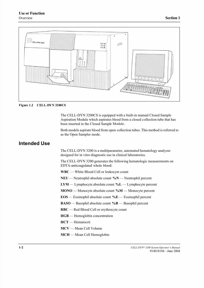
8/21/2019 Equ22-14 CellDyn3200 Op Man
http://slidepdf.com/reader/full/equ22-14-celldyn3200-op-man 54/690
1-2 CELL-DYN ® 3200 System Operator’s Manual
9140181M—June 2004
Use or Function
Overview Section 1
Figure 1.2 CELL-DYN 3200CS
The CELL-DYN 3200CS is equipped with a built-in manual Closed Sample
Aspiration Module which aspirates blood from a closed collection tube that has
been inserted in the Closed Sample Module.
Both models aspirate blood from open collection tubes. This method is referred to
as the Open Sampler mode.
Intended Use
The CELL-DYN 3200 is a multiparameter, automated hematology analyzerdesigned for in vitro diagnostic use in clinical laboratories.
The CELL-DYN 3200 generates the following hematologic measurements on
EDTA-anticoagulated whole blood:
WBC — White Blood Cell or leukocyte count
NEU — Neutrophil absolute count %N — Neutrophil percent
LYM — Lymphocyte absolute count %L — Lymphocyte percent
MONO — Monocyte absolute count %M — Monocyte percent
EOS — Eosinophil absolute count %E — Eosinophil percent
BASO — Basophil absolute count %B — Basophil percent
RBC — Red Blood Cell or erythrocyte count
HGB — Hemoglobin concentration
HCT — Hematocrit
MCV — Mean Cell Volume
MCH — Mean Cell Hemoglobin

8/21/2019 Equ22-14 CellDyn3200 Op Man
http://slidepdf.com/reader/full/equ22-14-celldyn3200-op-man 55/690
CELL-DYN ® 3200 System Operator’s Manual 1-3
9140181H—October 2001
Section 1 Use or Function
MCHC — Mean Cell Hemoglobin Concentration
RDW — Red Cell Distribution Width
PLT — Platelet or thrombocyte count
MPV — Mean Platelet Volume
PDW*— Platelet Distribution Width
PCT* — Plateletcrit
Retic % —Reticulocyte Percent
Retic Abs —Reticulocyte Absolute Count
* Clinical significance has not been established for these parameters. Therefore,
they are not reportable.

8/21/2019 Equ22-14 CellDyn3200 Op Man
http://slidepdf.com/reader/full/equ22-14-celldyn3200-op-man 56/690
1-4 CELL-DYN ® 3200 System Operator’s Manual
9140181H—October 2001
Use or Function
Overview Section 1
NOTES

8/21/2019 Equ22-14 CellDyn3200 Op Man
http://slidepdf.com/reader/full/equ22-14-celldyn3200-op-man 57/690
CELL-DYN ® 3200 System Operator’s Manual 1-5
9140181H—October 2001
Section 1 Use or Function
System Components
The CELL-DYN 3200 consists of three major modules, the Analyzer, DataModule, and the Display Station. The Analyzer and Data Module are housed in
single chassis. The Display Station is a standalone module. Figure 1.3 lists the
major subassemblies in each of the modules.
The Analyzer contains the hardware to aspirate, dilute, and analyze each whole
blood specimen.
The Data Module contains the components for analyzing, storing, and reporting
specimen results.
The Display Station module consists of a 15" color monitor and pressure-sensitive
keypad for selecting the displayed commands that operate the system.
The Sample Loader attaches to the front of the CELL-DYN 3200SL Analyzer andis an integral part of the SL model. The Sample Loader is discussed throughout this
manual where appropriate. It is also discussed in detail in Section 13: Sample
Loader .
Figure 1.3 CELL-DYN 3200 System Components
CELL-DYN 3200 System
Analyzer
Flow PanelElectrical Power Supply
Pneumatic Power SupplyLaser Optics AssemblySyringe Drive AssembliesOpen Sample Probe AssemblyReagent/Waste SystemClosed Sample Tower Assembly
Sample Loader (SL model only)
Data Module
486 Computer Floppy Disk Drive
Hard Disk DrivePC KeyboardSerial/Parallel Interface PortsPrinted Circuit Boards
Display Station
15" Color Monitor Membrane Keypad

8/21/2019 Equ22-14 CellDyn3200 Op Man
http://slidepdf.com/reader/full/equ22-14-celldyn3200-op-man 58/690
1-6 CELL-DYN ® 3200 System Operator’s Manual
9140181H—October 2001
Use or Function
System Components Section 1
Analyzer Components
The major components of the Analyzer are listed below and shown in Figures 1.4
through 1.8.
Front PanelRight Front Cover
Left Front Cover
Front Skirt Cover (CS model)
Sample Loader (SL model)
Status Indicator Panel
Closed Sample Tower Cover
Open Sample Aspiration Probe with Touch Plate
Flow Panel
Closed Sample Aspiration Tower Module
Shear Valve Assembly
Syringes (4)
Sample Transfer Peristaltic Pump
Optical Flow Cell Assembly
Laser Optics Bench Assembly (behind Flow Panel)
HGB Flow Cell/Mixing Assembly
WBC Mixing Chamber
RBC/PLT Mixing Chamber
Open Sample Aspiration Probe and Wash Block
Normally Closed Valves (6)
Diluent Reservoirs (2)
Open/Closed Mode Switching Assembly (Y Valve Assembly)
Waste Chambers (4)
Venting Chamber
Bubble Traps
Aerosol Filter
Normally Open Pinch Valves
Ultrasonic Sensor
LED Sensor
Diluent/Sheath Filter
Left Side Panel
Fan
Right Side Panel
Floppy Disk Drive Slot

8/21/2019 Equ22-14 CellDyn3200 Op Man
http://slidepdf.com/reader/full/equ22-14-celldyn3200-op-man 59/690
CELL-DYN ® 3200 System Operator’s Manual 1-7
9140181H—October 2001
Section 1 Use or Function
Rear Panel
Main Power Switch
Main Power Connector
Display Station Communications Connector
Line Frequency and Line Voltage Select Switches
Fuse
Fan with Air Intake Filter
Serial and Parallel Interface Ports (Data Module)
Keyboard Connector Port
Touch Pad Connector Port
Waste Sensor Connector
Waste Outlet Tube Connector
Diluent/Sheath Inlet Tube Connector
WBC Lyse Inlet Tube Connector
HGB Lyse Inlet Tube Connector
Analyzer Serial Number Label
Disk Storage Container

8/21/2019 Equ22-14 CellDyn3200 Op Man
http://slidepdf.com/reader/full/equ22-14-celldyn3200-op-man 60/690
1-8 CELL-DYN ® 3200 System Operator’s Manual
9140181M—June 2004
Use or Function
System Components Section 1
Component Description
Front Panel
The major components of the Front Panel are depicted in Figure 1.4. A brief
description of each component’s function follows.
Figure 1.4 CELL-DYN 3200SL Analyzer Front Panel
Left Front Cover
The Left Front Cover protects the left portion of the flow panel. The cover ishinged on the left, opening from the center to expose the left half of the flow panel.
Access to the left half of the flow panel is necessary to view the operation of the
left flow panel components, to access the solenoids, pinch valves, normally closed
valves, and to perform certain maintenance procedures. The cover is held in place
by hinges and magnetic fasteners (located on the top inside edge of the cover).
Right Front Cover
The Right Front Cover protects the right portion of the flow panel and supports
the Touch Plate and Status Indicator Panel. The cover is hinged on the right,
opening from the center to expose the right half of the flow panel. Access to the
right half of the flow panel is necessary to view the action of the right flow panel
components, to access the syringe assemblies, solenoids, pinch valves, normally
closed valves, and to perform certain maintenance procedures.
The cover is held in place by hinges and magnetic fasteners (located on the top
inside edge of the cover).
1 Left Front Cover
2 Right Front Cover
3 Status Indicator Panel
4 Aspiration Probe
5 Touch Plate
6 Sample Loader
7 Tower Cover
1 2
4
5
6
7
3

8/21/2019 Equ22-14 CellDyn3200 Op Man
http://slidepdf.com/reader/full/equ22-14-celldyn3200-op-man 61/690
CELL-DYN ® 3200 System Operator’s Manual 1-9
9140181H—October 2001
Section 1 Use or Function
Front Skirt Cover (not pictured)
The Front Skirt Cover protects the lower front part of the flow panel. The skirt
should be removed to access the two lower Normally Closed Valves on the left side
of the Flow Panel. The Skirt is removed from the instrument by removing the four
Phillips-head screws holding the Skirt to the Analyzer. The Skirt on the SL model
has two removable sections adjacent to the Flow Panel. The section on the rightside should be removed to provide easy access to all four syringes and two syringe
drives.
Status Indicator Panel
Three Status Indicator Messages (illuminated by green, yellow and red LEDs)
indicate the status of the Analyzer. The status messages are:
• READY (green light) —the Analyzer is ready to process a specimen
• BUSY (yellow light) —the Analyzer is busy with a normal operational
sequence
• FAULT (red light) —the Analyzer is unable to process specimens due to anexisting fault condition
(Open Sample) Aspiration Probe
The Open Sample Aspiration Probe is used to aspirate whole blood from an
opened collection tube. The wash block moves down to the end of the probe and
returns to a position that is covered by the Right Front Cover. When Closed
Sampler mode is selected, the Wash Block moves down to the end of the probe and
remains down until the Open Sampler mode is again selected.
Touch Plate
The Touch Plate is used to start the run cycle for (1) both the Open Sampler andClosed Sampler modes on the CS model and (2) Open Sampler mode only on the
SL model. It is located directly behind the Open Sample Aspiration Probe and is
part of the Right Front Cover. Pressing the Touch Plate starts the selected run cycle.
Sample Loader
See Subsection: Sample Loader Components later in this section.
(Closed Sample) Tower Cover
The Closed Sample Tower Cover protects the Tower Assembly and Shear Valve.
The Tower Cover for the SL model is larger than its counterpart on the CS model
in order to cover the top central portion of the Sample Loader. Part of the cover istranslucent to allow viewing of the Shear Valve’s operation. The cover is held in
place by two pins at the bottom and magnetic fasteners at the top. Both covers have
an Interlock Sensor Switch which prevents the instrument from operating in the
Closed Mode if the cover is not in place.
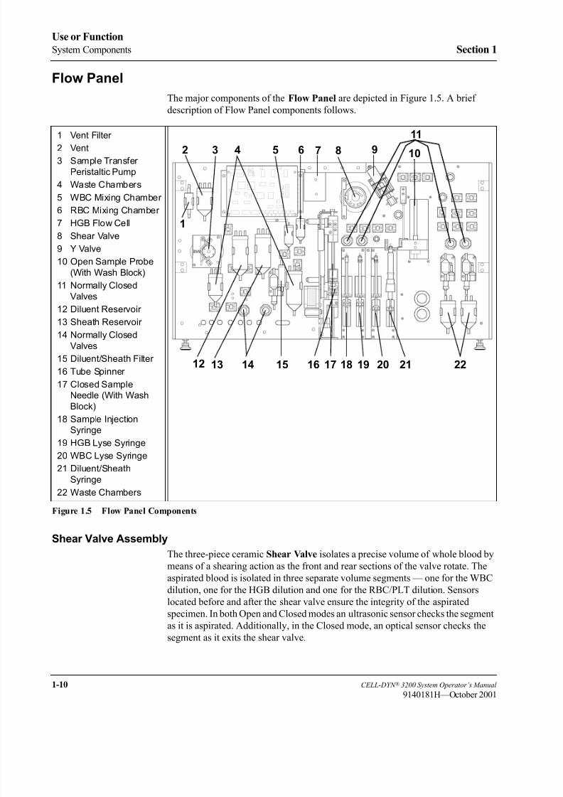
8/21/2019 Equ22-14 CellDyn3200 Op Man
http://slidepdf.com/reader/full/equ22-14-celldyn3200-op-man 62/690
1-10 CELL-DYN ® 3200 System Operator’s Manual
9140181H—October 2001
Use or Function
System Components Section 1
Flow Panel
The major components of the Flow Panel are depicted in Figure 1.5. A brief
description of Flow Panel components follows.
Figure 1.5 Flow Panel Components
Shear Valve Assembly
The three-piece ceramic Shear Valve isolates a precise volume of whole blood bymeans of a shearing action as the front and rear sections of the valve rotate. The
aspirated blood is isolated in three separate volume segments — one for the WBC
dilution, one for the HGB dilution and one for the RBC/PLT dilution. Sensors
located before and after the shear valve ensure the integrity of the aspirated
specimen. In both Open and Closed modes an ultrasonic sensor checks the segment
as it is aspirated. Additionally, in the Closed mode, an optical sensor checks the
segment as it exits the shear valve.
1 Vent Filter 2 Vent
3 Sample Transfer
Peristaltic Pump
4 Waste Chambers
5 WBC Mixing Chamber
6 RBC Mixing Chamber
7 HGB Flow Cell
8 Shear Valve
9 Y Valve
10 Open Sample Probe
(With Wash Block)
11 Normally Closed
Valves
12 Diluent Reservoir
13 Sheath Reservoir
14 Normally Closed
Valves
15 Diluent/Sheath Filter
16 Tube Spinner
17 Closed Sample
Needle (With Wash
Block)
18 Sample InjectionSyringe
19 HGB Lyse Syringe
20 WBC Lyse Syringe
21 Diluent/Sheath
Syringe
22 Waste Chambers
2 3 4 8 91110
1
5 6 7
12 13 14 15 16 18 19 20 21 2217

8/21/2019 Equ22-14 CellDyn3200 Op Man
http://slidepdf.com/reader/full/equ22-14-celldyn3200-op-man 63/690
CELL-DYN ® 3200 System Operator’s Manual 1-11
9140181H—October 2001
Section 1 Use or Function
Syringe Assembly
There are two syringe driver assemblies, each containing two syringes. Each
syringe is operated by its own stepper motor. The function of each syringe is
described below:
• Diluent/Sheath Syringe — (1) delivers a specific volume of diluent to
transport the RBC segment from the Shear Valve to the RBC/PLT Mixing
Chamber and to dilute the segment prior to measurement, and (2) delivers a
specific volume of diluent to transport the HGB segment from the Shear
Valve to the HGB Mixing Chamber and to dilute the segment prior to
measurement.
• HGB Lyse Syringe — delivers a specific volume of HGB Lyse to the HGB
Mixing Chamber/Flow Cell to further dilute the HGB segment prior to
measurement.
• WBC Lyse Syringe — delivers a specific volume of WBC Lyse to transport
the WBC segment from the Shear Valve to the WBC Mixing Chamber and to
dilute the segment prior to measurement.• Sample Injection Syringe — injects a specific volume of the diluted sample
into the Optical Flow Cell for RBC/PLT, WBC (WOC), and WBC (NOC)
measurements.
Sample Transfer Peristaltic Pump
The Sample Transfer Peristaltic Pump is composed of a rotor and a pump tube
holder. It is used to transfer the WBC dilution, RBC/PLT dilution, and HGB/NOC
dilution to the Optical Flow Cell from their respective mixing chambers.
HGB Flow Cell and Mixing Chamber
The HGB Flow Cell Assembly is integrated with a mixing chamber and containsthe following components:
• A fully enclosed (light-tight) mixing chamber with optical windows and
electronics
• An LED Light Source
• A Photodetector for measuring the light transmitted.
WBC Mixing Chamber
The WBC Mixing Chamber is used to swirl mix the WBC dilution.
RBC/PLT Mixing Chamber The RBC/PLT Mixing Chamber is used to swirl mix the RBC/PLT dilution.
Wash Block
There are two Wash Blocks on the instrument, one for the Open Sample Aspiration
Probe and one for the Closed Sample Needle. Both Wash Blocks work in a similar
fashion: After aspiration, they move down the outside of the probe or needle,
rinsing it with diluent. The diluent rinse is then transferred to the waste chamber.
8/21/2019 Equ22-14 CellDyn3200 Op Man
http://slidepdf.com/reader/full/equ22-14-celldyn3200-op-man 64/690
1-12 CELL-DYN ® 3200 System Operator’s Manual
9140181H—October 2001
Use or Function
System Components Section 1
Normally Closed Valves
The Normally Closed Valves prevent the backflow of reagents in critical areas
when the power is turned off.
Diluent Reservoir
The Diluent Reservoir maintains the diluent supply for cleaning and sample
dilution.
Sheath Reservoir
The Sheath Reservoir maintains a constant sheath supply for hydrodynamic
focusing in the Flow Cell.
Waste Chambers
The Waste Chambers collect the waste liquid from the Analyzer flow panel.
Bubble Traps
The Bubble Traps (not shown) are used to prevent bubbles and liquid from being
pulled into the vacuum accumulators and the vacuum pump.
Aerosol Filter
The Aerosol Filter (not shown) is used to prevent aerosols escaping into the
atmosphere.
Pinch Valves
The Pinch Valves (not shown) are used to control air and liquid throughout the
Analyzer.
Closed Mode Aspiration Tower
The Aspiration Tower contains the Aspiration/Vent Needle, Needle Wash Block,
Sample Tube Spinner Assembly, and tubing to aspirate blood samples from closed
sample tubes.
Vent/Aspiration Needle
The Vent/Aspiration Needle combines both venting and aspiration of blood
samples from closed sample tubes.
Wash Block
Discussed in the previous subsection.
Spinner Assembly
The Spinner Assembly consists of a tube holder, motor, and belt. These are
attached to the Closed Mode Aspiration Needle drive mechanism, and they move
up and down in tandem with the needle. As the Spinner Assembly and needle
descend together, the spinning tube holder centers and rotates the sample tube,
allowing the Bar Code Reader to read the bar code on the sample tube. After the
bar code is read, the needle penetrates the rubber stopper and aspirates the sample.

8/21/2019 Equ22-14 CellDyn3200 Op Man
http://slidepdf.com/reader/full/equ22-14-celldyn3200-op-man 65/690
CELL-DYN ® 3200 System Operator’s Manual 1-13
9140181H—October 2001
Section 1 Use or Function
Bar Code Reader
The Bar Code Reader is an LED type and can accommodate Code 39, Code 128,
CODABAR, and Interleaved 2 of 5 formats. On the CS model, the Bar Code
Reader is located to the right of the door opening on the Door Assembly. On the SL
model, the Bar Code Reader is located to the left of the Mixing Assembly on the
Sample Loader.
Door Assembly (CS Model)
The Door Assembly consists of a tube holder/door, Bar Code Reader, Interlock
Switch, and electrical latch to open the door after aspiration has occurred. The
Interlock Switch will cause the instrument to halt if the door is opened between the
time the Touch Plate is pressed and the system emits a beep to indicate that
aspiration is completed. Opening the door during this period will cause a Fatal
Fault condition.
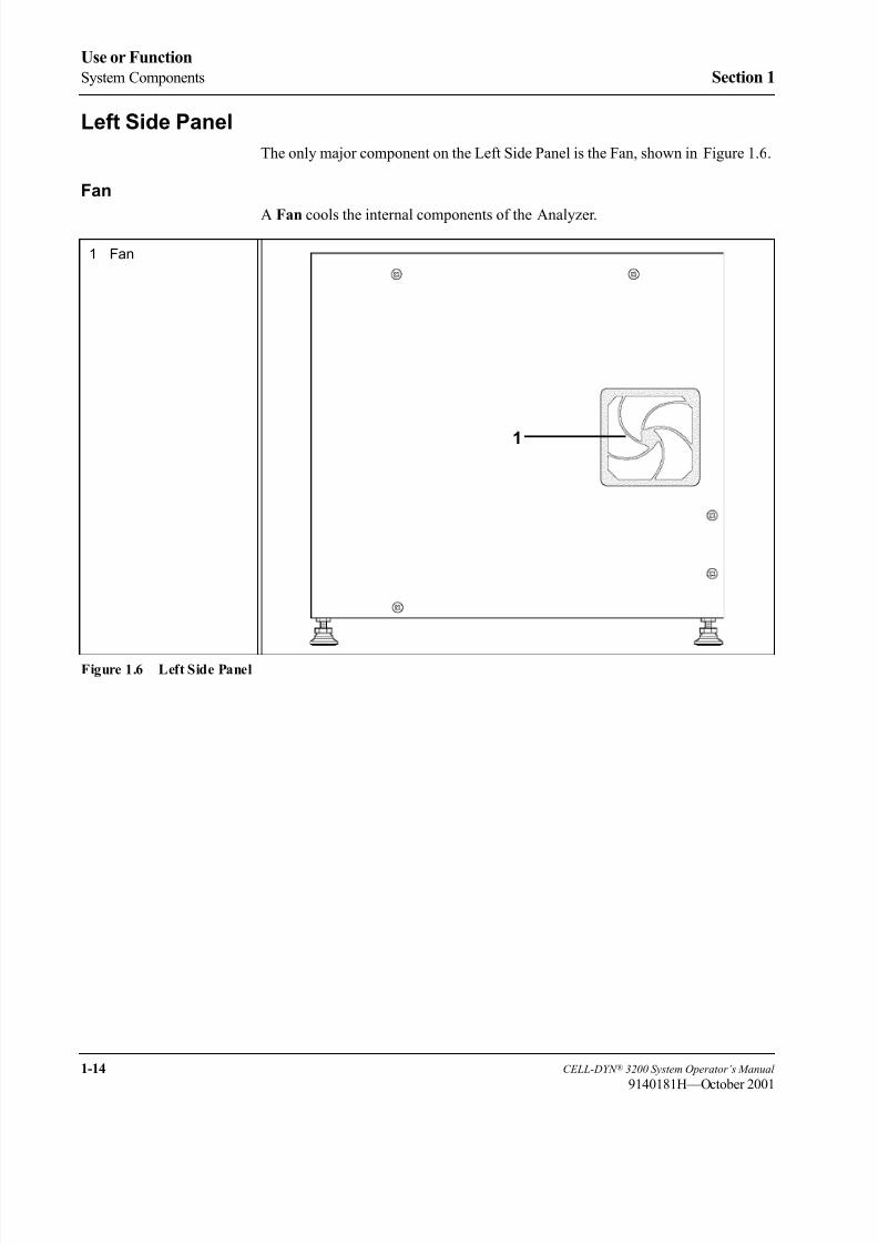
8/21/2019 Equ22-14 CellDyn3200 Op Man
http://slidepdf.com/reader/full/equ22-14-celldyn3200-op-man 66/690
1-14 CELL-DYN ® 3200 System Operator’s Manual
9140181H—October 2001
Use or Function
System Components Section 1
Left Side Panel
The only major component on the Left Side Panel is the Fan, shown in Figure 1.6.
Fan
A Fan cools the internal components of the Analyzer.
Figure 1.6 Left Side Panel
1 Fan
1

8/21/2019 Equ22-14 CellDyn3200 Op Man
http://slidepdf.com/reader/full/equ22-14-celldyn3200-op-man 67/690
CELL-DYN ® 3200 System Operator’s Manual 1-15
9140181H—October 2001
Section 1 Use or Function
Right Side Panel
The only major component on the Right Side Panel is the Floppy Disk Drive shown
in Figure 1.7.
Figure 1.7 Right Side Panel Components
Floppy Disk Drive (Slot)
The Floppy Disk Drive allows information to be downloaded or uploaded using a
3.5" floppy disk.
1 Floppy Disk Drive Slot
1

8/21/2019 Equ22-14 CellDyn3200 Op Man
http://slidepdf.com/reader/full/equ22-14-celldyn3200-op-man 68/690
1-16 CELL-DYN ® 3200 System Operator’s Manual
9140181M—June 2004
Use or Function
System Components Section 1
Rear Panel
The major components on the Rear Panel are depicted in Figure 1.8. A brief
functional description of the main components follows.
Figure 1.8 Rear Panel Components
Main Power Switch
The Main Power Switch turns on power for the Analyzer, Data Module, and
Sample Loader (SL model only).
Analyzer Serial Number LabelAlthough not an instrument component, the Analyzer Serial Number may be
required when consulting Abbott Customer Service.
Data Module
See Subsection: Data Module Components later in this section.
Disk Storage Container
This container is used to store the Installation and Set Up disks.
Fan
A Fan cools the internal components of the Analyzer.
1 Main Power Switch2 Analyzer Serial
Number
3 Data Module
4 Disk Storage
Container
5 Fan
6 Ground Connector
7 Waste Sensor
Connector
8 Waste Outlet Tube
Connector
9 Reagent Inlet Panel
10 Power Supply Module
1
2
3
4 5
7 8
9
6
10

8/21/2019 Equ22-14 CellDyn3200 Op Man
http://slidepdf.com/reader/full/equ22-14-celldyn3200-op-man 69/690
CELL-DYN ® 3200 System Operator’s Manual 1-17
9140181H—October 2001
Section 1 Use or Function
Waste Sensor Connector
The waste-full sensor plug connects to the Waste Sensor Connector port. The
ground shield on the cable should be attached to the Ground Connector on the
rear panel. When the electrical sensor is tripped, the EXTERNAL WASTE FULL
message is generated and the READY status is inhibited until the situation is
corrected. The Analyzer interprets a disconnected plug the same way as a full wastecontainer. Therefore, if the waste is routed to a drain, the dummy plug (supplied in
the accessory kit) must be inserted in the connector.
Waste Outlet Tube Connector
This port is used to connect the waste outlet tube.
Reagent Inlet Panel
Diluent/Sheath Inlet Tube Connector
This color-coded (red) port is used to connect the diluent inlet tube with its
associated cap, sinker and label.
WBC Lyse Inlet Tube Connector
This color-coded (purple) port is used to connect the WBC lyse inlet tube with its
associated cap, sinker and label.
HGB Lyse Inlet Tube Connector
This color-coded (blue) port is used to connect the HGB lyse inlet tube with its
associated cap, sinker and label.
Power Supply Module
The Power Supply Module supplies the power to operate the Analyzer and DataModule.

8/21/2019 Equ22-14 CellDyn3200 Op Man
http://slidepdf.com/reader/full/equ22-14-celldyn3200-op-man 70/690
1-18 CELL-DYN ® 3200 System Operator’s Manual
9140181L—July 2003
Use or Function
System Components Section 1
Line Frequency and Line Voltage Select Switches
These switches are used to select the Line Frequency and Voltage for the Analyzer
(refer to Figure 1.9).
WARNING: These switches are set at the factory for 120 volts. When operation at
other line voltage is required, refer to Figure 1.9.
Figure 1.9 Power Supply Module
Main Power Connector
This receptacle is used to connect the main power cord to the instrument.
Fuse
An 8-amp (110/120 V) T (Slo-Blo) or 4-amp (220/240 V) T (Slo-Blo) Fuse
protects the Analyzer from electrical spikes.
PN 9230003F
WARNING: SET FOR 120 VOLTS / ACHTUNG: FR 120 VOLT EINGESTELLT /
ADVARSEL: KONFIGURERET TIL 120 V / VARNING: INSTLLD FR 120 VOLT /
Consult instructions for use if different voltage is required. / Ist der Betrieb mit einer anderenNetzspannung erforderlich, in der Bedienungsanleitung nachlesen. / Si une utilisation unetension diffrente est requise, consulter les instructions d’utilisation. / Consulte las instrucciones deuso si la tensin es distinta. / Per un voltaggio diverso, consultare le istruzioni per l’uso. /Se for necessria uma voltagem diferente, consultar as instrues de utilizao. /Se brugermanualen, hvis der er behov for drift med en anden netspnding. / Ls tillhrandedokumentation om en annan spnning behvs. / Για χρήση σε άλλη τάση ρεύµατος,συµβουλευτείτε τις οδηγίες χρήσης.
ΠΡΟΕΙ∆ΟΠΟΙΗΣΗ:ΧΡΗΣΗ ΣΤΑ 120 VOLTS
MISE EN GARDE : UTILISATION A 120 VOLTS / ADVERTENCIA: 120 VOLTIOS /AVVERTENZA: CONFIGURATO A 120 VOLT / AVISO: CONFIGURADO PARA 120 VOLTS /
1 Line Voltage Select
Switch
2 Line Frequency Select
Switch
3 Main Power
Connector
4 Fuse
3
2
1
4

8/21/2019 Equ22-14 CellDyn3200 Op Man
http://slidepdf.com/reader/full/equ22-14-celldyn3200-op-man 71/690
CELL-DYN ® 3200 System Operator’s Manual 1-19
9140181K—July 2002
Section 1 Use or Function
Top Panel
Flow Cell Assembly
The Flow Cell Assembly contains the fluidics and hardware needed to
hydrodynamically focus the RBC/PLT and WBC sample streams in the path of the
laser beam for analysis. The primary components of this assembly are:
• Sample Feed Nozzle — a specially designed tube used to deliver the diluted
sample into the sheath stream
• Sample Flow Cell — an optically clear quartz chamber with a central square
opening of a specific size, which flares out into a cone at the bottom of the
flow cell
Laser Optics Bench Assembly
The Laser Optics Bench Assembly (located behind the Flow Panel) contains the
Helium-Neon laser, the flow cell, and the optics and detectors required for
enumeration and differentiation of white blood cells, red blood cells, and platelets(refer to Figure 1.10).
Figure 1.10 Optical Bench
1 Orthogonal (90° and
90°D) Scatter Light
Detectors
2 Laser Tube
3 Forward Angle (0° and
10°) Scatter Light
Detectors
4 Optical Flow Cell
5 Laser
12
3
45
CAUTION–
CLASS3BLASERLIGHTWHENOPEN.
AVOIDEXPOSURETOBEAM.PN 923 7 1

8/21/2019 Equ22-14 CellDyn3200 Op Man
http://slidepdf.com/reader/full/equ22-14-celldyn3200-op-man 72/690
1-20 CELL-DYN ® 3200 System Operator’s Manual
9140181H—October 2001
Use or Function
System Components Section 1
Data Module Components
The major components of the Data Module are depicted in Figure 1.11. A
description of each component’s function follows.
Figure 1.11 Data Module Components - Rear Panel
Computer (inside the Data Module)
• Intel 486DX microprocessor
• 8 megabytes RAM (expandable to 16 megabytes)
• VGA graphics with 1 megabyte cache
• 2 enhanced parallel ports and 2 serial ports
• 2 FIFO UART Com1 and Com2 ports
• 3 PCI slots
Data Storage
Data storage consists of a 3.5-inch, 1.4 megabyte Floppy Disk Drive and a one
gigabyte EIDE (enhanced IDE) Hard Disk Drive.
1 PC KeyboardConnector
2 COM1 (LIS
Connector)
3 COM2 (Unused)
4 Analyzer BDM
Diagnostics (Unused)
5 HSSL Connector
6 HSSL Connector
7 Membrane Keyboard
Interface Connector
8 Display Station
Interface Connector 9 Ticket Printer
Connector
10 Graphics Printer
Connector
1
2
3
4
5
6
7
8
9
10

8/21/2019 Equ22-14 CellDyn3200 Op Man
http://slidepdf.com/reader/full/equ22-14-celldyn3200-op-man 73/690
CELL-DYN ® 3200 System Operator’s Manual 1-21
9140181H—October 2001
Section 1 Use or Function
The floppy disk drive is used to update the software program and to download data.
The hard drive is used to store the User Interface Software and Patient Data Log.
It has sufficient capacity to store the most recent 10,000 cycles, including numeric
and graphics data.
Printed Circuit BoardsA set of Printed Circuit Boards constitutes the measurement and control
electronics for detection, amplification, and processing of signals.
PC Keyboard Connector
The PC Keyboard Connector port is used to connect the standard computer
keyboard.
LIS (Laboratory Information System) Connector
Two serial ports are provided. COM1 is used to connect the Laboratory
Information System to the Data Module. COM2 is unused.
Analyzer BDM Diagnostics (Unused)
HSSL (High Speed Serial Link) Connectors
The High Speed Serial Link transfers data between the Analyzer and the Data
Module. The HSSL Connector on the Data Module connects to the HSSL
Connector on the back panel of the Analyzer.
Membrane Keypad Interface Connector
The Membrane Keypad Interface Connector allows data to be sent from the
Membrane Keypad on the Display Monitor to the Data Module.
Display Station Interface Connector
The Display Station Interface Connector allows data to be sent to the monitor
and data to be received from the Membrane Keypad (Soft Keys) on the Display
Station.
Ticket Printer Connector
This port is used to connect the printer cable when the printer is used to print data
in a ticket format.
Graphics Printer Connector
This port is used to connect the printer cable when the printer is used to print datain a graphics format.
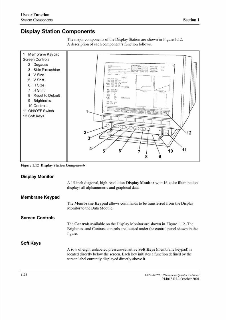
8/21/2019 Equ22-14 CellDyn3200 Op Man
http://slidepdf.com/reader/full/equ22-14-celldyn3200-op-man 74/690
1-22 CELL-DYN ® 3200 System Operator’s Manual
9140181H—October 2001
Use or Function
System Components Section 1
Display Station Components
The major components of the Display Station are shown in Figure 1.12.
A description of each component’s function follows.
Figure 1.12 Display Station Components
Display Monitor
A 15-inch diagonal, high-resolution Display Monitor with 16-color illumination
displays all alphanumeric and graphical data.
Membrane Keypad
The Membrane Keypad allows commands to be transferred from the Display
Monitor to the Data Module.
Screen Controls
The Controls available on the Display Monitor are shown in Figure 1.12. TheBrightness and Contrast controls are located under the control panel shown in the
figure.
Soft Keys
A row of eight unlabeled pressure-sensitive Soft Keys (membrane keypad) is
located directly below the screen. Each key initiates a function defined by the
screen label currently displayed directly above it.
1 Membrane KeypadScreen Controls
2 Degauss
3 Side Pincushion
4 V Size
5 V Shift
6 H Size
7 H Shift
8 Reset to Default
9 Brightness
10 Contrast
11 ON/OFF Switch12 Soft Keys
1
2
3
45 6 7
8 9
10 11
12

8/21/2019 Equ22-14 CellDyn3200 Op Man
http://slidepdf.com/reader/full/equ22-14-celldyn3200-op-man 75/690
CELL-DYN ® 3200 System Operator’s Manual 1-23
9140181H—October 2001
Section 1 Use or Function
Video Cable (not shown)
The Video Cable allows data from the Data Module to be transferred to the Display
Monitor.
Power Cord (not shown)
A built-in power cord on the Display Station connects to an outside power supply
and provides power to the monitor and keypad.
Sample Loader Components
The major components of the Sample Loader are depicted in Figure 1.13.
A description of each component’s function follows.
Figure 1.13 Sample Loader Components
Racks
Each Sample Loader Rack is able to accommodate up to 10 tubes. Racks are
labeled with rack number and tube position, and with a 2-digit Bar Code 39 format.
1 Aspiration Needle
2 Wash Block
3 Spinner Motor
4 Tube Spinner 5 Tube Mixer Assembly
6 Bar Code Reader
6
5
4
3
1
2
8/21/2019 Equ22-14 CellDyn3200 Op Man
http://slidepdf.com/reader/full/equ22-14-celldyn3200-op-man 76/690
1-24 CELL-DYN ® 3200 System Operator’s Manual
9140181L—July 2003
Use or Function
System Components Section 1
Tower Cover
The Tower Cover on the SL model, although not part of the Sample Loader, has
an Interlock Sensor Switch which prevents the loader from operating if the cover
is not in place. If the cover is removed during operation, the Sample Loader comes
to an immediate halt, causing a fatal fault. This feature provides further safety for
the operator.
Bar Code Reader
The Bar Code Reader is an LED type and can accommodate Code 39, Code 128,
CODABAR, and Interleaved 2 of 5 formats. On the SL model, the Bar Code
Reader is located on the Sample Loader. It reads the bar code on the tube when the
tube is at the aspiration station.
Tube Sensor Assembly
The Tube Sensor Assembly senses the presence of a sample tube at each Mixing
Station. The Tube Deflector (brush) positions the sample tube closer to the Tube
Sensor.
Tube Mixer Assembly
The Mixer Assembly consists of a double-tube holder directly attached to a
stepper motor. As the rack advances, the tube holder descends and grabs the tube.
The tube holder rotates 15 times in an outward motion of approximately 135
degrees. The double-tube configuration of the tube holder allows each tube to be
held and mixed twice in succession before it passes to the mixing station. An air
cylinder governs the rotation movement of the tube holder.
Closed Sample Aspiration Tower Module
The Closed Sample Aspiration Tower is used to aspirate whole blood from aclosed collection tube. It is used when the Closed Sampler mode is selected on
either the SL or CS model. The configuration of the Tower Module differs
depending on the model.
In the CS model, the Tower Module consists of the following components:
• Aspiration/Vent Needle
• Wash Block
• Tube Spinner (includes motor and belt)
• Door Assembly (includes Tube Holder, Bar Code Reader, Swivel Door,
Solenoid, and Interlock Switch).
In the SL model, the Tower Module consists of the following components:
• Aspiration/Vent Needle
• Wash Block
• Tube Spinner (includes motor and belt)
The Door Assembly is eliminated from the Tower, and the Bar Code Reader is
moved to the Sample Loader which also contains the Mixer Assembly.

8/21/2019 Equ22-14 CellDyn3200 Op Man
http://slidepdf.com/reader/full/equ22-14-celldyn3200-op-man 77/690
CELL-DYN ® 3200 System Operator’s Manual 1-25
9140181H—October 2001
Section 1 Use or Function
The major components of the Tower Module are briefly described below:
• A two-part Needle consisting of a venting needle and an aspiration needle
that pierces the collection tube stopper, vents vacuum or pressure from inside
the tube, aspirates the whole blood, and is retracted for rinsing at the end of
each cycle
• A Tube Spinner to grasp and spin the tube for bar code reading
• The Driver Motor and Belt to operate the Tube Spinner
• A Closed Sample Door/Tube Retainer which holds a single closed
collection tube in the proper position for (1) reading the bar code if
applicable, and (2) stopper penetration and sample aspiration by the needle
Printer
The Printer is discussed in detail in Section 12: Printers.
Reagent System
Introduction
The Reagent System is formulated specifically for the CELL-DYN 3200 Series
instrument flow systems in order to provide optimal system performance. Use of
reagents other than those specified in this manual is not recommended as
instrument performance can be affected. Each CELL-DYN 3200 system is checked
at the factory using the specified reagents and all performance claims are generated
using these reagents.
The reagents used with the CELL-DYN 3200 are:
• RBC/PLT Reagent - Diluent/Sheath
• WBC Reagent - WBC Lyse
• HGB Reagent - CN-Free HGB/NOC Lyse
• Reticulocyte Reagent
Reagents must be stored at room temperature to ensure optimal performance. All
reagents should be protected from direct sunlight, extreme heat and freezing during
shipment and storage. Temperatures below 32° F (0°C) may cause reagent layering
that changes the tonicity and conductivity of the reagents.
CAUTION: If any reagent has been frozen, it must not be used.
The reagent inlet tubes have a cap attached that minimizes evaporation and
contamination during use. However, reagent quality may deteriorate with time.
Therefore, use all reagents within the dating period indicated on the label.
8/21/2019 Equ22-14 CellDyn3200 Op Man
http://slidepdf.com/reader/full/equ22-14-celldyn3200-op-man 78/690
1-26 CELL-DYN ® 3200 System Operator’s Manual
9140181H—October 2001
Use or Function
System Components Section 1
CELL-DYN Reagents
CELL-DYN 3200 Diluent/Sheath (List Number 03H79-01)
CELL-DYN Diluent/Sheath is formulated to meet the following requirements:
• Act as the diluent for the RBCs, PLTs, and hemoglobin
• Maintain the stable diluted cell volume of each red cell and platelet during
the count and sizing portion of the measurement cycle
• Serve as a sheath fluid for the hydrodynamic focusing process
• Serve as a rinsing agent for the fluidics system
• Provide background counts equal to or less than:
WOC: 0.10 x K/µL
NOC: 0.10 x K/µL
RBC: 0.02 x M/µL
HGB: 0.10 x g/dL
PLT: 5.0 x K/µL
CELL-DYN 3200 CN-Free HGB/NOC Lyse (List Number 03H80-02)
CELL-DYN CN-Free HGB/NOC Lyse is formulated to meet the following
requirements:
• Rapidly lyse the red blood cells and minimize the resultant stroma
• Strip the white cell cytoplasm leaving the nuclear membrane intact so the
white cell nuclei can be enumerated
• Convert hemoglobin to a stable chromagen complex that is measurable at555 nm.
CELL-DYN 3200 WBC Lyse (List Number 03H78-01)
CELL-DYN WBC Lyse is formulated to meet the following requirements:
• Act as the diluent for the WBCs
• Osmotically lyse the red cells
• Maintain the light scattering properties of the WBCs for the duration of the
measurement period
• Provide sufficient wetting action to prevent accumulation of air bubbles inthe WBC flow system
• Maintain a WOC background count equal to or less than 0.10 x K/µL
• Act as a diluent for Reticulocytes
8/21/2019 Equ22-14 CellDyn3200 Op Man
http://slidepdf.com/reader/full/equ22-14-celldyn3200-op-man 79/690
CELL-DYN ® 3200 System Operator’s Manual 1-27
9140181M—June 2004
Section 1 Use or Function
Reticulocyte Reagent System—CELL-DYN Reticulocyte Reagent(List Number 03H40-01)
CELL-DYN Reticulocyte Reagent is formulated specifically to provide optimal
system performance for the CELL-DYN 3200 Reticulocyte procedure. Use of
reagents other than those specified in this manual is not recommended becauseinstrument performance can be affected. Each CELL-DYN 3200 System is
checked at the factory using the specified reagents and all performance claims were
generated using these reagents.
Reagent must be stored in the dark at room temperature. All reagents should be
protected from direct sunlight, extreme heat, and freezing during storage.
CAUTION: If any reagent has been frozen, it must not be used.
Reagent tubes have been capped to minimize evaporation. However, reagent
quality may deteriorate with time. Therefore, use all reagents within the dating
period indicated on the label.
Consumables
The following consumables are used with the CELL-DYN 3200 System:
• Preprinted tickets
• Color Ink Cartridges
• Lint-free pads
• Enzymatic Cleaner Concentrate
For information on ordering parts and accessories, reagents, controls, calibrators,
and consumables, please refer to Appendix B - Parts and Accessories.

8/21/2019 Equ22-14 CellDyn3200 Op Man
http://slidepdf.com/reader/full/equ22-14-celldyn3200-op-man 80/690
1-28 CELL-DYN ® 3200 System Operator’s Manual
9140181H—October 2001
Use or Function
System Components Section 1
NOTES

8/21/2019 Equ22-14 CellDyn3200 Op Man
http://slidepdf.com/reader/full/equ22-14-celldyn3200-op-man 81/690
CELL-DYN ® 3200 System Operator’s Manual 2-1
9140181H—October 2001
Section 2 Installation Procedures and Special Requirements
ec on nsta at on roce ures an pec a equ rements
Overview
Installation of the CELL-DYN 3200 should be performed by an authorized Abbottrepresentative to ensure that all system components are functioning correctly and
to verify system performance.
NOTE: Installation of the Analyzer by an unauthorized or untrained person could
result in damage to the system. Never attempt to install the system without
an authorized Abbott representative present.
The remainder of this chapter gives general requirements for a successful
installation. Procedures are also included for installing the Printer and Sample
Loader.
Initial Preparation
Package Inspection and Inventory
The instrument is shipped from the factory as follows:
CELL-DYN 3200SL
• 1 crate containing the instrument including Sample Loader
• 1 box containing the CELL-DYN Accessory kit and Sample Loader
Accessory kit
• 1 box containing the Color Graphics Printer
• 1 box containing the Ticket Printer (optional)
• CELL-DYN Reagents
• CELL-DYN Operator’s Manual
CELL-DYN 3200CS
• 1 crate containing the instrument
• 1 box containing the CELL-DYN Accessory Kit
• 1 box containing the Color Graphics Printer
• 1 box containing the Ticket Printer (optional)
• CELL-DYN Reagents• CELL-DYN Operator’s Manual

8/21/2019 Equ22-14 CellDyn3200 Op Man
http://slidepdf.com/reader/full/equ22-14-celldyn3200-op-man 82/690
2-2 CELL-DYN ® 3200 System Operator’s Manual
9140181L—July 2003
Installation Procedures and Special Requirements
Overview Section 2
CELL-DYN Accessory Kit
• Keyboard Cover
• Fuse, SB 8.0 amps 110/120V (2)
• Fuse, SB 4.0 amps 220/240V (2)
• Printer Paper 9.5" x 11"
• Power Cord (Analyzer)
• Reagent Line Kit
• Printer Cable
• 10' long Tygon® tubing
• Diluent/Sheath filters
• Large Peristaltic Pump Tubing
• Waste Dummy Plug
• Wire Puller (Solenoids)
• RS232 Plug (Loop back)
Sample Loader Accessory Kit
• 5 Tube Racks (Pre-labeled)
The instrument will be uncrated and inspected for damage by the trucking company
when the system is delivered. If desired, the trucking company will transport the
instrument to the laboratory and place it in the designated space.
Inspect the remaining boxes for damage. If there is any damage, or if any crates or
boxes are missing, contact Abbott Customer Service for assistance.
The reagents needed for installation are shipped when the instrument is shipped.
This shipment includes: WBC Lyse Reagent, CN-Free HGB/NOC Lyse Reagent,
and Diluent/Sheath Reagent.
The calibrator and controls needed for the installation are shipped when the
instrument is shipped. This shipment includes: CELL-DYN Calibrator and
Tri-level Control.
If any reagents, calibrator or control materials are missing, contact Abbott
Customer Service for assistance.
8/21/2019 Equ22-14 CellDyn3200 Op Man
http://slidepdf.com/reader/full/equ22-14-celldyn3200-op-man 83/690
CELL-DYN ® 3200 System Operator’s Manual 2-3
9140181M—June 2004
Section 2 Installation Procedures and Special Requirements
Space Requirements
Approximately 6 linear feet of space is required on the counter top to accommodate
the instrument, display station, and printer. Sufficient space is required beneath for
the reagents and the waste container (if one is used).
Do not position the instrument so that it is difficult to operate the main power
switch.
Allow six inches of space above and behind the instrument and 12 inches above
and in front of the fan on the left side of the instrument for air flow. In addition,
allow adequate space around the instrument to perform necessary maintenance
procedures, to provide service access, and to allow the instrument to be easily
disconnected from its power source.
Locate the instrument:
• On a stable, level surface
• On a nonporous, nonabsorbent work surface and flooring that can be easily
cleaned and disinfected using recommended procedures• Away from direct sunlight
• Away from the path of a cooled or heated air outlet
• Away from any other instruments that may interfere with it, such as a
centrifuge, any x-ray equipment, MRI equipment, a CRT, a video terminal, a
computer, or a copier
Place the reagents below the instrument.
Waste Disposal Requirements
Observe the following requirements for waste routing and disposal:
• Allow room for a suitable, properly labeled, waste container or position the
instrument to permit the waste to be routed directly to a drain suitable for
disposal of waste. The drain must be suitable for waste that could present a
biological or chemical hazard.
• If routing waste to a waste container, ensure the Waste Sensor is properly
connected.
• If routing waste to a drain, make sure the Dummy Plug is inserted into the
SENSOR port.
• Users are responsible for disposing of waste in accordance with local, state,
and federal regulations.
WARNING: Potential Biohazard. The waste is under pressure. Be sure
that the Waste Outlet Tube is securely placed in the drain hole or waste box,
flow of waste is unobstructed, and all System components are located away
from possible waste overflow.

8/21/2019 Equ22-14 CellDyn3200 Op Man
http://slidepdf.com/reader/full/equ22-14-celldyn3200-op-man 84/690
2-4 CELL-DYN ® 3200 System Operator’s Manual
9140181H—October 2001
Installation Procedures and Special Requirements
Overview Section 2
Power Requirements
Be sure that the system is located at the desired site before attempting any
connections. A minimum of three power outlets are required for either model: one
outlet for the Analyzer, one for the Printer, and one for the Display Station. If a
Ticket Printer will also be installed, a fourth power outlet will be needed. Grounded
power outlets and a voltage regulator for the Analyzer are required for optimum performance.

8/21/2019 Equ22-14 CellDyn3200 Op Man
http://slidepdf.com/reader/full/equ22-14-celldyn3200-op-man 85/690
CELL-DYN ® 3200 System Operator’s Manual 2-5
9140181M—June 2004
Section 2 Installation Procedures and Special Requirements
Tubing Installation
Reagent and Waste Tubing1. Locate the reagent tubing in the Accessory Kit.
2. Inspect each length of tubing carefully for damage or cracks.
3. Attach the non-weighted end of the tubing with the Purple WBC Lyse label
to the Purple Connector on the right side of the Rear Panel. (Refer to Figure
2.1.) This reagent is for the WBC dilution. Wipe the outside of the tubing
with a damp lint-free pad and place the weighted end into the container of
CELL-DYN WBC Lyse. Secure the cap. Place the container on the same
level as or lower than the unit.
4. Attach the non-weighted end of the tubing with the Red Diluent/Sheath
label to the Red Connector. This reagent is for the RBC dilution and forrinsing the flow system. Wipe the outside of the tubing with a damp lint-free
pad and place the weighted end into the container of CELL-DYN Diluent/
Sheath. Secure the cap. Place the container on the same level as or lower
than the unit.
5. Attach the non-weighted end of the tubing with the Blue HGB Lyse label to
the Blue Connector. This reagent is for the HGB dilution. Wipe the outside
of the tubing with a damp lint-free pad and place the weighted end into the
container of CELL-DYN HGB Lyse. Secure the cap. Place the container on
the same level as or lower than the unit .
6. Attach the Waste Outlet Tubing to the Waste Outlet Connector. Place the
end of the tubing with the cap and sensor into the waste collection container.
Ensure that the waste collection container is adequately labeled. Secure the
cap, or remove the cap from the tubing and place the tubing into a drain
suitable for collection of waste with possible biological and chemical hazard .
Be sure that the tubing is secured to the drain hole.

8/21/2019 Equ22-14 CellDyn3200 Op Man
http://slidepdf.com/reader/full/equ22-14-celldyn3200-op-man 86/690
2-6 CELL-DYN ® 3200 System Operator’s Manual
9140181M—June 2004
Installation Procedures and Special Requirements
Tubing Installation Section 2
Figure 2.1 Reagent Inlet Panel
7. Locate the Waste-Full Sensor Plug attached to the cap's electrode wires.
Insert the plug into the Waste Sensor connector located on the Reagent Inlet
Panel. Attach the ground shield on the cable to the connection on the rear
panel.
If the waste tube is placed directly into a drain, insert the Dummy Plug
(provided in the Accessory kit) into the Waste Sensor Connector, as the
EXTERNAL WASTE FULL alert will activate if no plug is inserted. For
information on ordering a Waste Dummy Plug, refer to Appendix B — Parts
and Accessories.
Normally Closed Valves
To gain access to all six Normally Closed Valves on the Flow Panel, open both the
Left and Right Front Covers and remove the Tower Cover. Remove the Front Skirt
(CS model) or move the Sample Loader (SL model) away from the instrument.
(Refer to instructions later in this section for opening and removing thesecomponents.)
Before shipment, the tubing is removed from these valves. To ensure correct
system operation, the tubing must be completely inserted in all the valves before
the instrument power is turned ON. Follow the directions below to open the front
covers and remove the Skirt or Sample Loader to allow access to all the Normally
Closed Valves. Refer to Figure 2.2.
1 Waste Full Sensor
2 Waste Outlet
Connector
3 HGB Lyse Connector
4 Diluent/Sheath
Connector
5 WBC Lyse Connector
1 2 3 4 5

8/21/2019 Equ22-14 CellDyn3200 Op Man
http://slidepdf.com/reader/full/equ22-14-celldyn3200-op-man 87/690
CELL-DYN ® 3200 System Operator’s Manual 2-7
9140181M—June 2004
Section 2 Installation Procedures and Special Requirements
Figure 2.2 Analyzer Front Covers — SL Model
Open Left Front Cover
To open the Left Front Cover on both the SL and CS models, gently pull on the
hand hold to release it. Swing the cover all the way to the left to completely expose
the left side of the Flow Panel.
Open Right Front Cover
To open the Right Front Cover on both the SL and CS models, gently pull on thehand hold to release it. Swing the cover all the way to the right to completely
expose the right side of the Flow Panel. Because of the attached Touch Plate and
Status Panel, this cover should not be removed from the instrument.
Remove Tower Cover
To remove the Tower Cover on both the SL and CS (tower door on the CS model
must be open) models, rotate tower away from front panel using hand hold. Lift
bottom of cover off skirt locating pins and gently pull the top of the cover away
from the analyzer.
Remove Front SkirtTo remove the Front Skirt Cover on the CS model, remove the four Phillips-head
screws, two on either side of the instrument, which hold the skirt to the instrument
frame. Pull the skirt away from the instrument.
1 Left Front Cover
2 Right Front Cover
3 Touch Plate
4 Phillips-head Screws
5 Sample Loader 6 Tower Cover
1 2
6 3
45
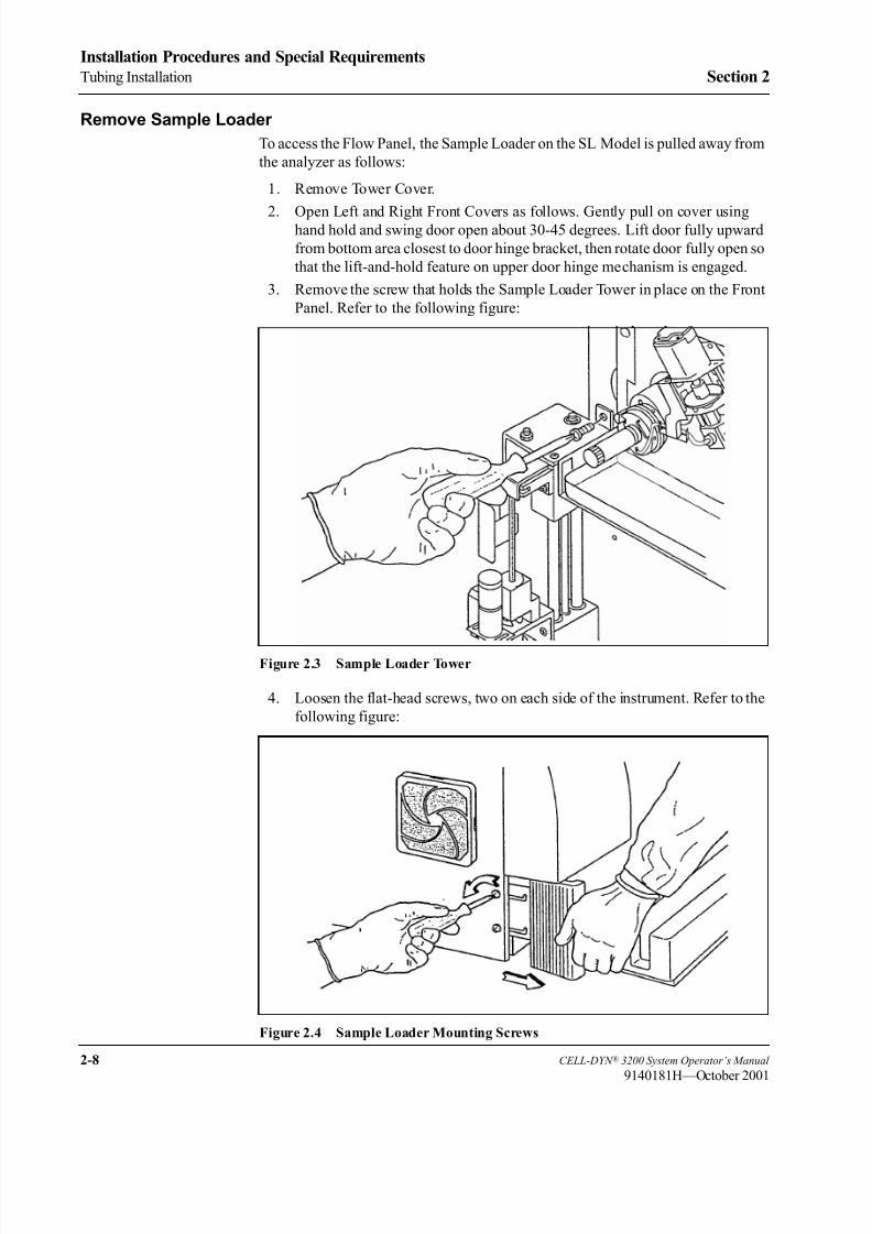
8/21/2019 Equ22-14 CellDyn3200 Op Man
http://slidepdf.com/reader/full/equ22-14-celldyn3200-op-man 88/690
2-8 CELL-DYN ® 3200 System Operator’s Manual
9140181H—October 2001
Installation Procedures and Special Requirements
Tubing Installation Section 2
Remove Sample Loader
To access the Flow Panel, the Sample Loader on the SL Model is pulled away from
the analyzer as follows:
1. Remove Tower Cover.
2. Open Left and Right Front Covers as follows. Gently pull on cover usinghand hold and swing door open about 30-45 degrees. Lift door fully upward
from bottom area closest to door hinge bracket, then rotate door fully open so
that the lift-and-hold feature on upper door hinge mechanism is engaged.
3. Remove the screw that holds the Sample Loader Tower in place on the Front
Panel. Refer to the following figure:
Figure 2.3 Sample Loader Tower
4. Loosen the flat-head screws, two on each side of the instrument. Refer to the
following figure:
Figure 2.4 Sample Loader Mounting Screws
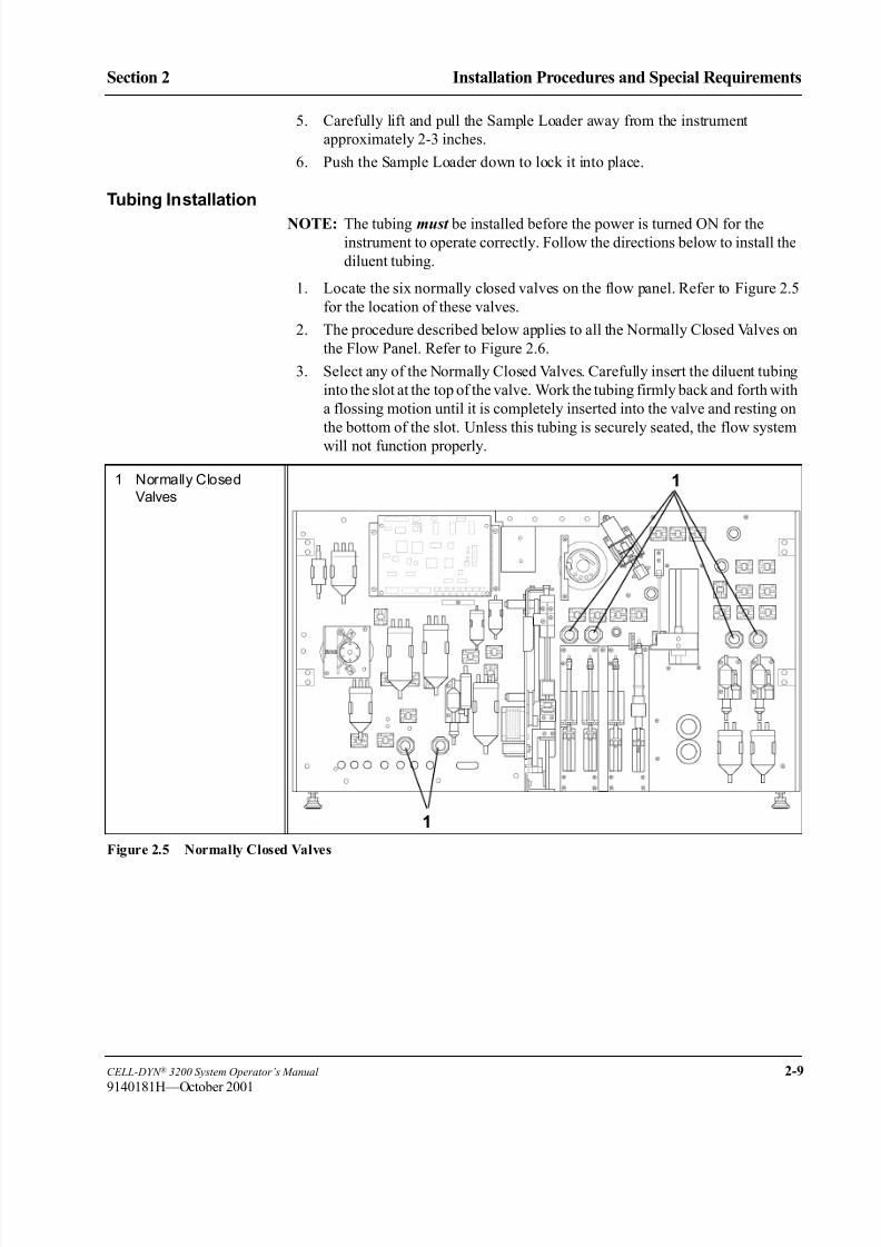
8/21/2019 Equ22-14 CellDyn3200 Op Man
http://slidepdf.com/reader/full/equ22-14-celldyn3200-op-man 89/690
CELL-DYN ® 3200 System Operator’s Manual 2-9
9140181H—October 2001
Section 2 Installation Procedures and Special Requirements
5. Carefully lift and pull the Sample Loader away from the instrument
approximately 2-3 inches.
6. Push the Sample Loader down to lock it into place.
Tubing Installation
NOTE: The tubing must be installed before the power is turned ON for the
instrument to operate correctly. Follow the directions below to install the
diluent tubing.
1. Locate the six normally closed valves on the flow panel. Refer to Figure 2.5
for the location of these valves.
2. The procedure described below applies to all the Normally Closed Valves on
the Flow Panel. Refer to Figure 2.6.
3. Select any of the Normally Closed Valves. Carefully insert the diluent tubing
into the slot at the top of the valve. Work the tubing firmly back and forth with
a flossing motion until it is completely inserted into the valve and resting on
the bottom of the slot. Unless this tubing is securely seated, the flow system
will not function properly.
Figure 2.5 Normally Closed Valves
1 Normally Closed
Valves
1
1
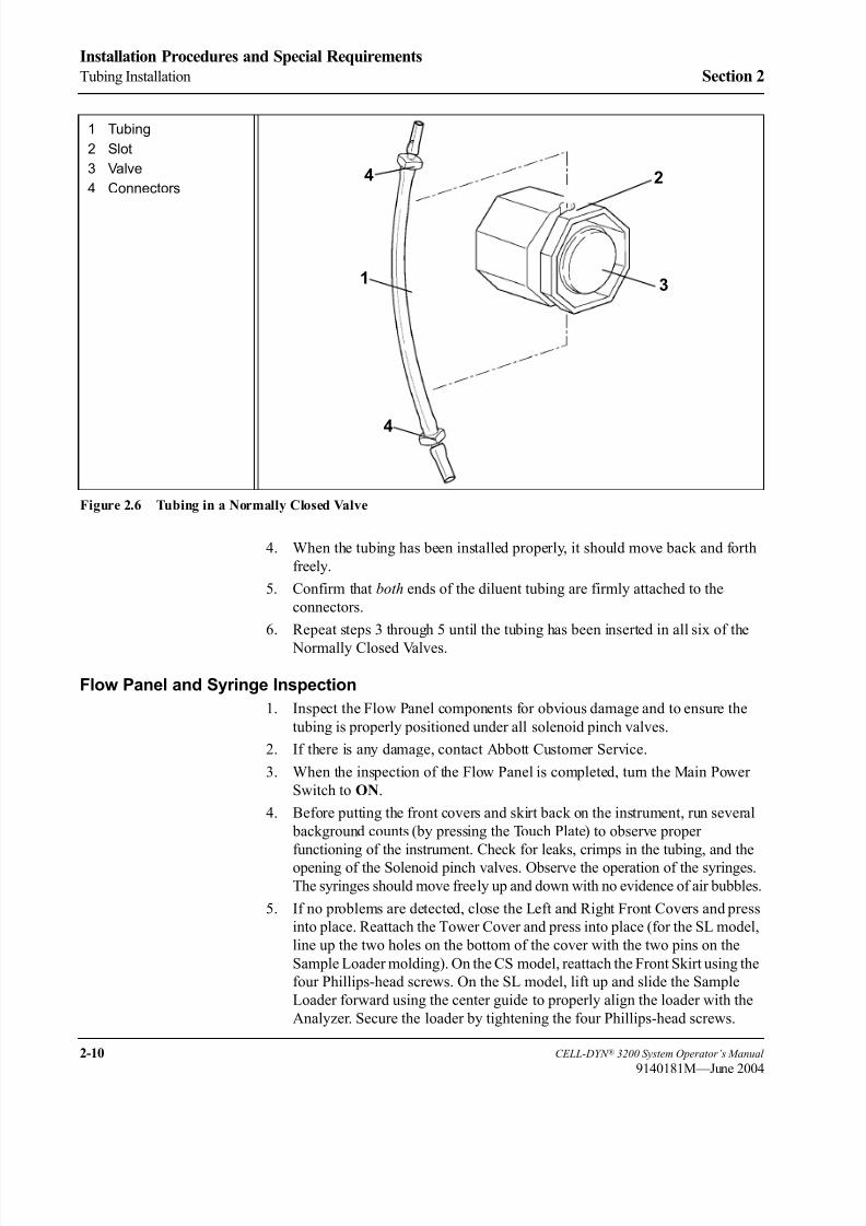
8/21/2019 Equ22-14 CellDyn3200 Op Man
http://slidepdf.com/reader/full/equ22-14-celldyn3200-op-man 90/690
2-10 CELL-DYN ® 3200 System Operator’s Manual
9140181M—June 2004
Installation Procedures and Special Requirements
Tubing Installation Section 2
Figure 2.6 Tubing in a Normally Closed Valve
4. When the tubing has been installed properly, it should move back and forth
freely.
5. Confirm that both ends of the diluent tubing are firmly attached to the
connectors.
6. Repeat steps 3 through 5 until the tubing has been inserted in all six of the
Normally Closed Valves.
Flow Panel and Syringe Inspection
1. Inspect the Flow Panel components for obvious damage and to ensure the
tubing is properly positioned under all solenoid pinch valves.
2. If there is any damage, contact Abbott Customer Service.
3. When the inspection of the Flow Panel is completed, turn the Main Power
Switch to ON.
4. Before putting the front covers and skirt back on the instrument, run several
background counts (by pressing the Touch Plate) to observe proper
functioning of the instrument. Check for leaks, crimps in the tubing, and the
opening of the Solenoid pinch valves. Observe the operation of the syringes.
The syringes should move freely up and down with no evidence of air bubbles.
5. If no problems are detected, close the Left and Right Front Covers and press
into place. Reattach the Tower Cover and press into place (for the SL model,
line up the two holes on the bottom of the cover with the two pins on the
Sample Loader molding). On the CS model, reattach the Front Skirt using the
four Phillips-head screws. On the SL model, lift up and slide the Sample
Loader forward using the center guide to properly align the loader with the
Analyzer. Secure the loader by tightening the four Phillips-head screws.
1 Tubing
2 Slot
3 Valve
4 Connectors
1
2
3
4
4
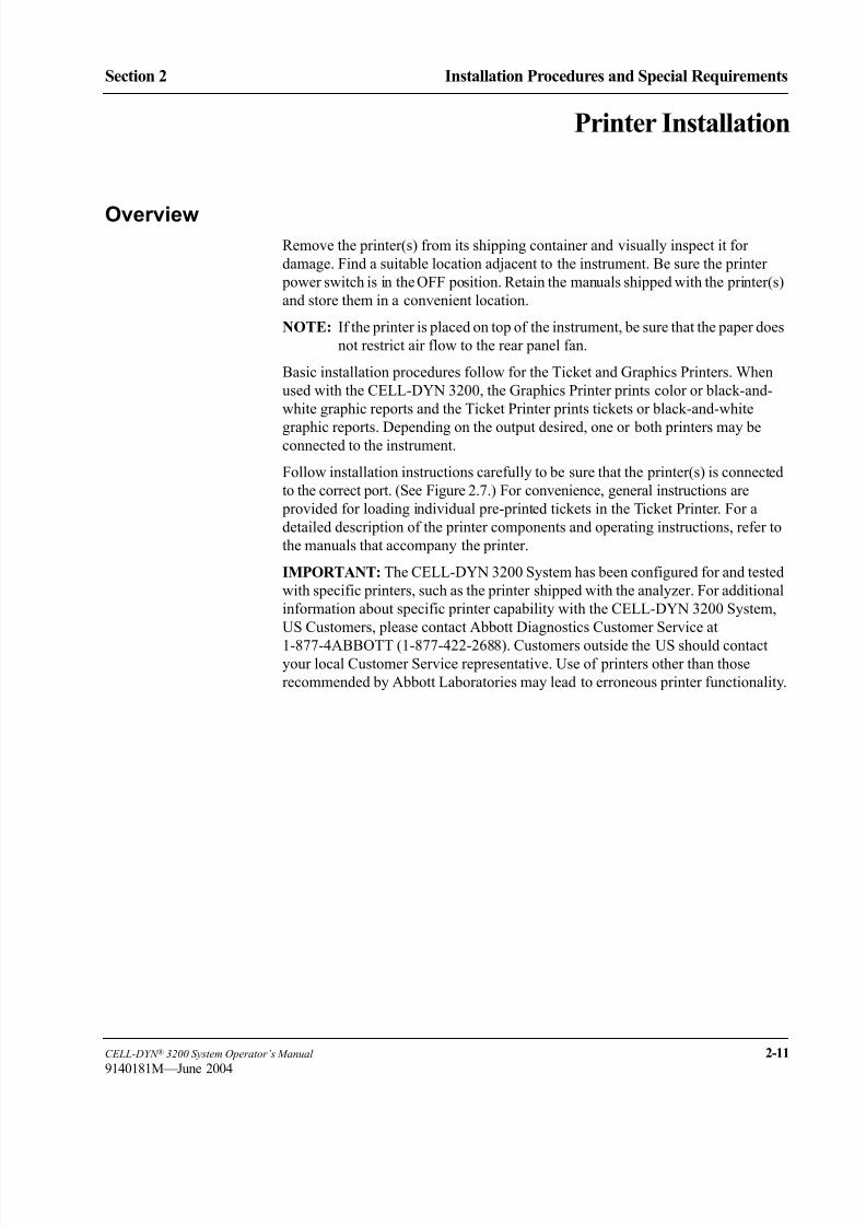
8/21/2019 Equ22-14 CellDyn3200 Op Man
http://slidepdf.com/reader/full/equ22-14-celldyn3200-op-man 91/690
CELL-DYN ® 3200 System Operator’s Manual 2-11
9140181M—June 2004
Section 2 Installation Procedures and Special Requirements
Printer Installation
OverviewRemove the printer(s) from its shipping container and visually inspect it for
damage. Find a suitable location adjacent to the instrument. Be sure the printer
power switch is in the OFF position. Retain the manuals shipped with the printer(s)
and store them in a convenient location.
NOTE: If the printer is placed on top of the instrument, be sure that the paper does
not restrict air flow to the rear panel fan.
Basic installation procedures follow for the Ticket and Graphics Printers. When
used with the CELL-DYN 3200, the Graphics Printer prints color or black-and-
white graphic reports and the Ticket Printer prints tickets or black-and-white
graphic reports. Depending on the output desired, one or both printers may beconnected to the instrument.
Follow installation instructions carefully to be sure that the printer(s) is connected
to the correct port. (See Figure 2.7.) For convenience, general instructions are
provided for loading individual pre-printed tickets in the Ticket Printer. For a
detailed description of the printer components and operating instructions, refer to
the manuals that accompany the printer.
IMPORTANT: The CELL-DYN 3200 System has been configured for and tested
with specific printers, such as the printer shipped with the analyzer. For additional
information about specific printer capability with the CELL-DYN 3200 System,
US Customers, please contact Abbott Diagnostics Customer Service at
1-877-4ABBOTT (1-877-422-2688). Customers outside the US should contactyour local Customer Service representative. Use of printers other than those
recommended by Abbott Laboratories may lead to erroneous printer functionality.

8/21/2019 Equ22-14 CellDyn3200 Op Man
http://slidepdf.com/reader/full/equ22-14-celldyn3200-op-man 92/690
2-12 CELL-DYN ® 3200 System Operator’s Manual
9140181H—October 2001
Installation Procedures and Special Requirements
Printer Installation Section 2
Figure 2.7 CELL-DYN 3200 Printer Ports
Graphics Printer Installation Procedure1. Assemble the printer as directed in the printer manual.
2. Make sure that the printer power switch is OFF. Plug the power cord into the
printer. Do not plug the other end into an outlet until you are ready to load
paper.
3. Make sure that the power to the instrument is turned OFF. Remove the printer
cable (which looks like a power cord with two connectors) from the
Accessory kit and plug one end into the parallel port on the rear of the printer.
(There is a metal plate covering the printer’s serial port to avoid confusion.)
Fasten the wire clips to the connector for a secure connection.
4. Plug the other end of the printer cable into the Graphics Printer port on the
back of the Data Module. (See Figure 2.7) Tighten the screws on theconnector for a secure connection.
NOTE: This port is configured for use as a graphics printer only. To print
tickets, you may connect a Ticket Printer to the Ticket Printer port.
5. Install the ink cartridge as directed in the printer manual.
6. Load the paper as directed in the printer manual.
7. If necessary, refer to Section 5: Operating Instructions; Subsection:
Customize Report for instructions on customizing the printout.
1 Graphics Printer Port
2 Ticket Printer Port
1
2

8/21/2019 Equ22-14 CellDyn3200 Op Man
http://slidepdf.com/reader/full/equ22-14-celldyn3200-op-man 93/690
CELL-DYN ® 3200 System Operator’s Manual 2-13
9140181L—July 2003
Section 2 Installation Procedures and Special Requirements
Self-Test Printouts
Run any self-test printouts before using the printer for the first time. These self-
tests may be run any time to verify proper printer operation.
The CELL-DYN 3200 software automatically controls and adjusts most print
conditions for the Graphics Printer, including page width. If printing is not what
you expect, refer to the printer manual for guidance in making adjustments. If you
have additional questions or experience any problems, call Abbott Customer
Service for assistance.
Ticket Printer Installation Procedure
The Ticket Printer is an OKIDATA® MICROLINE® 320 dot matrix printer or
compatible printer.
The Ticket Printer is normally used to print result data on blank or pre-printed
tickets but can be used to print a complete graphics report on continuous tractor-
feed paper. (Blank tickets are available in continuous tractor-feed sheets.
Pre-printed tickets must be loaded individually.)
1. Assemble the printer as directed in the printer manual.
2. Make sure that the printer power switch is OFF. Plug the power cord into the
back of the printer and plug the other end into a grounded outlet.
3. Make sure that the power to the instrument is turned OFF. Remove the printer
cable (which looks like a power cord with two connectors) from the
Accessory kit and plug one end into the port on the rear of the printer. (The
port is constructed so that the connector will only fit in the proper way.)
Fasten the wire clips to the connector for a secure connection.
4. Plug the other end of the printer cable into the Ticket Printer port on the back
of the Data Module. (See Figure 2.7.) Tighten the screws on the connector for
a secure connection.
NOTE: This port is configured for use as a ticket printer only. To print
graphics reports, you may connect a Graphics Printer to the
Graphics Printer port.
5. Install the ribbon as directed in the printer manual.
6. Load the paper or blank, continuous-feed tickets as directed in the printer
manual, OR, if you are using pre-printed individual tickets, continue with the
following procedure.
IMPORTANT

8/21/2019 Equ22-14 CellDyn3200 Op Man
http://slidepdf.com/reader/full/equ22-14-celldyn3200-op-man 94/690
2-14 CELL-DYN ® 3200 System Operator’s Manual
9140181H—October 2001
Installation Procedures and Special Requirements
Printer Installation Section 2
Loading Individual Tickets in the Ticket Printer
Instructions are given for loading individual tickets. If fanfold, continuous-feed
tickets are used, they should be loaded as directed in the printer manual for tractor-
feed paper.
NOTE: To print on these tickets, the printer cable must be connected to the Ticket
Printer Connector.
1. Be sure that the printer is turned OFF and the printer cable is connected to the
Ticket Printer connector on the back of the instrument. If the connection is
incorrect, turn the instrument power OFF, change the position of the cable
and turn the power back ON.
2. Set the ribbon cartridge headgap lever to adjust for the thickness of the
tickets. Refer to the printer manual for detailed instructions.
3. Move the paper selection lever to the rear position to select single-feed paper.
4. Open the access cover and be sure the guide wire on the paper separator is
pushed back into the locked position.
5. Raise the separator to its upright position.
6. Place a ticket on the paper separator and adjust the guides so that they barely
touch the edges of the ticket.
7. Pull the bail lever forward. The ticket will automatically feed into place.
Release the bail lever.
8. Be sure the printer is deselected (Sel indicator is not illuminated). Set the Top
of Form by pressing and holding the TOF/Quiet key and pressing the Form
Feed key to move the ticket up or pressing the Line Feed key to move the
ticket down. (The ticket moves in very fine increments so it can be precisely
positioned.)
NOTE: The ticket will only move down to a certain point to prevent
potential ticket jams. Do not move the top of the page below the
paper bail.
9. Position the ticket so that the lower red line on the paper shield (located
between the print head and the paper) is positioned where the first line of
printing should occur.
NOTE: When the Top of Form is set, the position is retained in the printer
memory until it is reset.
10. Press the Sel key to select the printer. The printer is now ready to print.
Self-Test Printouts
Run any self-test printouts indicated in the printer manual before using the TicketPrinter for the first time. These self-tests may be run any time to verify proper
printer operation.

8/21/2019 Equ22-14 CellDyn3200 Op Man
http://slidepdf.com/reader/full/equ22-14-celldyn3200-op-man 95/690
CELL-DYN ® 3200 System Operator’s Manual 2-15
9140181M—June 2004
Section 2 Installation Procedures and Special Requirements
Sample Loader Inspection (SL Model)
The Sample Loader is attached directly to the Analyzer to form an integrated unit,
as shown in Figure 2.8.
Four screws, two on either side, hold the Sample Loader to the Analyzer. A power
cord provides power from the Analyzer to the loader, and an interface cable allowscommunication between the Analyzer and loader. The Analyzer and Sample
Loader are also connected by two quick-disconnect tube lines, one for pressure and
one for vacuum.
The tube spinning and sample aspiration mechanism on the Tower Module is
identical on both the SL and CS models. The Tower Cover on the SL model differs
from its counterpart on the CS model in two ways:
1. It is larger in order to extend over the center portion of the Sample Loader
which contains the Bar Code Reader and Mixing Assembly.
2. It serves as a safety cover, halting operation of the Sample Loader if it is
removed.
Figure 2.8 Analyzer With Sample Loader
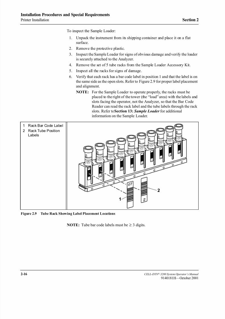
8/21/2019 Equ22-14 CellDyn3200 Op Man
http://slidepdf.com/reader/full/equ22-14-celldyn3200-op-man 96/690
2-16 CELL-DYN ® 3200 System Operator’s Manual
9140181H—October 2001
Installation Procedures and Special Requirements
Printer Installation Section 2
To inspect the Sample Loader:
1. Unpack the instrument from its shipping container and place it on a flat
surface.
2. Remove the protective plastic.
3. Inspect the Sample Loader for signs of obvious damage and verify the loaderis securely attached to the Analyzer.
4. Remove the set of 5 tube racks from the Sample Loader Accessory Kit.
5. Inspect all the racks for signs of damage.
6. Verify that each rack has a bar code label in position 1 and that the label is on
the same side as the open slots. Refer to Figure 2.9 for proper label placement
and alignment.
NOTE: For the Sample Loader to operate properly, the racks must be
placed to the right of the tower (the “load” area) with the labels and
slots facing the operator, not the Analyzer, so that the Bar Code
Reader can read the rack label and the tube labels through the rack
slots. Refer toSection 13: Sample Loader for additionalinformation on the Sample Loader.
Figure 2.9 Tube Rack Showing Label Placement Locations
NOTE: Tube bar code labels must be ≥ 3 digits.
1 Rack Bar Code Label
2 Rack Tube Position
Labels
1
2

8/21/2019 Equ22-14 CellDyn3200 Op Man
http://slidepdf.com/reader/full/equ22-14-celldyn3200-op-man 97/690
CELL-DYN ® 3200 System Operator’s Manual 2-17
9140181H—October 2001
Section 2 Installation Procedures and Special Requirements
Power On
1. Turn the instrument’s Main Power Switch to ON. When the initialization
process is complete, press the [RUN] key to prime the instrument. When the
priming process is complete, the READY light on the Analyzer’s indicator
panel is lit and the message READY is displayed in the Status Box on the
monitor.
2. Prime the Sample Loader by running several blood samples in the Closed
Mode. If necessary, refer to the directions given in Section 5: Operating
Instructions; Subsection: Sample Analysis on the CELL-DYN 3200SL,
Running Samples, Closed Mode Procedure.
3. Confirm that the background count is acceptable before running patient
samples.
8/21/2019 Equ22-14 CellDyn3200 Op Man
http://slidepdf.com/reader/full/equ22-14-celldyn3200-op-man 98/690
2-18 CELL-DYN ® 3200 System Operator’s Manual
9140181H—October 2001
Installation Procedures and Special Requirements
Printer Installation Section 2
NOTES

8/21/2019 Equ22-14 CellDyn3200 Op Man
http://slidepdf.com/reader/full/equ22-14-celldyn3200-op-man 99/690
CELL-DYN ® 3200 System Operator’s Manual 3-1
9140181H—October 2001
Section 3 Principles of Operation
Section 3 Principles of Operation
Overview
The principles the CELL-DYN 3200 uses to measure, count and calculate the
hematological parameters are discussed in Sample Analysis Cycle Overview and
Introduction to Flow Cytometry within this section. Subsequent sections discuss
the measurement process for WBC, RBC, PLT, and HGB. The last subsection,
Operational Messages and Data Flagging, discusses the flags generated by the
instrument due to measured parameters outside predefined limits, sample
abnormality, interference in the measurement process, or detection of an abnormal
subpopulation. Quality Control methodology is discussed in Section 11: Quality
Control . Reticulocytes and Reticulocyte flagging are discussed in
Section 14: Reticulocyte Package.
The two independent measurement channels used in the CELL-DYN 3200 are:
• The Optical channel for determining the WBC, NOC, and RBC/PLT data
• The Hemoglobin channel for determining the HGB
During each instrument cycle, the sample is aspirated, diluted, and mixed before
each parameter is measured.
NOTE: An increase in flags will occur in RRBC and FWBC modes.
Sample Aspiration
There are two modes of whole blood sample aspiration on the CELL-DYN 3200.
The operator selects the mode of aspiration from the RUN screen.
• The Open Sampler Mode is used to aspirate the sample from a collection
tube that has been opened and is held under the open sample aspiration probe.
• The Closed Sampler Mode is used to aspirate the blood directly from a closed
collection tube by piercing the tube stopper. On the CS model, sample tubes are
processed manually. On the SL model, sample tubes are processed
automatically using the Sample Loader.
The aspiration volumes are:
Open Mode 150 µL ± 10%
Closed Mode (CS) 240 µL ± 10%
Sample Loader (SL) 240 µL ± 10%
Once the mode of aspiration is selected, the whole blood sample is aspirated to the
Shear Valve by vacuum/pressure action. An ultrasonic sensor, located upstream of
the Shear Valve, checks the integrity of the sample stream before it enters the Shear
Valve. An LED sensor, located downstream of the Shear Valve, checks the sample
stream to ensure the proper amount of blood has been transferred through the Shear
Valve.

8/21/2019 Equ22-14 CellDyn3200 Op Man
http://slidepdf.com/reader/full/equ22-14-celldyn3200-op-man 100/690
3-2 CELL-DYN ® 3200 System Operator’s Manual
9140181H—October 2001
Principles of Operation
Overview Section 3
NOTES
8/21/2019 Equ22-14 CellDyn3200 Op Man
http://slidepdf.com/reader/full/equ22-14-celldyn3200-op-man 101/690
CELL-DYN ® 3200 System Operator’s Manual 3-3
9140181H—October 2001
Section 3 Principles of Operation
Sample Analysis Cycle Overview
NOTE: Sample and reagent volumes given in this section are stated as thenominal values. Slight differences between instruments may cause these
volumes to vary. These differences are compensated for by factory-set
internal dilution factors.
Sample Aspiration
A sample is aspirated either in Open Mode or Closed Mode and transferred to the
Shear Valve. The sample volume in Open Mode is 150 µL. The sample volume in
Closed Mode is 240 µL.
Sample Segments
The Shear Valve rotates in order to separate three volumes of the aspirated whole blood sample. The three volumes are:
20 µL for the WBC dilution
1.67 µL for the RBC/PLT dilution
12 µL for the HGB dilution
RBC/PLT Analysis
1. The Diluent/Sheath Syringe dispenses 2.79 mL of diluent through the Shear
Valve where the 1.67 µL RBC/PLT volume is transferred to the RBC Mixing
Chamber.
2. The segment and diluent are then routed to the RBC/PLT Mixing Chamber
where the dilution is swirl mixed. The final dilution is 1:1675.
3. The Sample Transfer Pump transfers the RBC/PLT dilution from the RBC/
PLT Mixing Chamber to the Optical Flow Cell Sample Feed Nozzle.
4. Diluent/Sheath reagent, under constant pressure in the Sheath Reservoir, is
directed into the Optical Flow Cell.
5. Sequentially, the Sample Metering Syringe injects 24 µL of the RBC/PLT
dilution into the flow cell at a pressure (and speed) lower than that of the
diluent/sheath reagent.
6. The higher speed of the sheath, which surrounds the RBC/PLT dilution, and
the special geometry of the flow cell combine to focus the RBC/PLT dilution
stream so that individual cells can be counted.
7. A laser beam is focused on the flow cell. As the sample stream intersects the
laser beam, the light scattered is measured at 0°, 10°, and 90° for red blood
cells, and at 0°and 10° for platelets.

8/21/2019 Equ22-14 CellDyn3200 Op Man
http://slidepdf.com/reader/full/equ22-14-celldyn3200-op-man 102/690
3-4 CELL-DYN ® 3200 System Operator’s Manual
9140181H—October 2001
Principles of Operation
Sample Analysis Cycle Overview Section 3
Hemoglobin Analysis
1. The Diluent/Sheath Syringe injects 1.7 mL of diluent through the Shear
Valve where the 12 µL HGB volume is transferred to the HGB Flow Cell.
2. The HGB Lyse Syringe dispenses 0.9 mL of HGB Lyse into the line after the
diluent has transferred the HGB volume to the HGB Flow Cell. The entry
point for the HGB Lyse is between the Shear Valve and the HGB Flow Cell.
3. The segment, lyse, and diluent are routed to the HGB Flow Cell where the
dilution is swirl mixed. The final dilution is 1:218.
4. A low-energy LED attached to the HGB Flow Cell measures the absorbance
of light at 555 nm. The absorbance is proportional to the HGB concentration
of the sample.
WBC Analysis
WBCs are analyzed optically as follows:
1. The WBC Lyse Syringe dispenses 0.973 mL of WBC Lyse reagent through
the shear valve where the 20 µL WBC volume is transferred to the WBCMixing Chamber.
2. The segment and reagent are then routed to the WBC Mixing Chamber where
the dilution is swirl mixed. The final dilution is 1:50. The diluted sample
remains in the mixing chamber for 14 seconds for the lysing of the red blood
cells.
3. The Sample Transfer Pump transfers the WBC dilution from the WBC
Mixing Chamber to the Optical Flow Cell Sample Feed Nozzle.
4. Diluent/Sheath reagent, under constant pressure in the Sheath Reservoir, is
directed into the Optical Flow Cell.
5. Sequentially, the Sample Metering Syringe injects 46.5 µL of the WBC
dilution into the flow cell at a pressure (and speed) lower than that of thediluent/sheath reagent.
6. The higher speed of the sheath, which surrounds the WBC dilution, and the
special geometry of the flow cell combine to focus the WBC dilution stream
so that individual cells can be counted.
7. A laser beam is focused on the flow cell. As the sample stream intersects the
laser beam, the light scattered by the cells is measured at four different
detectors located in the forward (0° and 10°) and side (90° and 90°D) angles.
8/21/2019 Equ22-14 CellDyn3200 Op Man
http://slidepdf.com/reader/full/equ22-14-celldyn3200-op-man 103/690
CELL-DYN ® 3200 System Operator’s Manual 3-5
9140181H—October 2001
Section 3 Principles of Operation
Fragile WBCs and Resistant RBCs
When running samples in the normal Patient mode, the operator may suspect the
presence of fragile WBCs when the FWBC flag is displayed or may suspect the
presence of resistant RBCs when the RRBC and NRBC flags are displayed.
In the case of samples containing fragile WBCs or resistant RBCs, an alternate
method is used to measure white blood cells. The results of this method are referred
to as the Nuclear Optical Count (NOC). The NOC measurement is derived from the
HGB dilution as described below. Refer to Nuclear Optical Count and Resistant
RBC later in this section for additional information.
There are two different key labels on the SPECIMEN TYPE screen, one for fragile
WBCs and one for resistant RBCs. Refer to Run Menu Soft Keys, Subsection:
Specimen Type in Section 5: Operating Instructions for a discussion of the
Specimen Types available.
When the Fragile WBC specimen type is selected, both NOC and WOC are
reported in the Data Log. The NOC value is reported as WBC on the RUN screen
and Laboratory Worksheet.
When the Resistant RBC specimen type is selected, both NOC and WOC are
reported in the Data Log. Either NOC or WOC is reported as WBC (based on
algorithmic decision-making) on the RUN screen and Laboratory Worksheet.
NOTE: When QC specimen type is selected, both NOC and WOC are reported in
the Data Log. Either NOC or WOC is reported as WBC (based on
algorithmic decision-making) on the RUN screen.
The analysis for Fragile WBC and Resistant RBC is performed as follows:
1. After the HGB sample is measured (refer to Hemoglobin Analysis earlier in
this section), the Sample Transfer Pump transfers the diluted solution from
the HGB Flow Cell to the Optical Flow Cell Sample Feed Nozzle.2. Diluent/Sheath reagent, under constant pressure in the Sheath Reservoir, is
directed into the Optical Flow Cell.
3. Sequentially, the Sample Metering Syringe injects 140 µL of the HGB
dilution into the flow cell.
4. The higher speed of the sheath which surrounds the HGB dilution, and the
special geometry of the flow cell, focus the HGB dilution stream so that
individual cells can be counted.
5. A laser beam is focused on the flow cell. As the sample stream intersects the
laser beam, the light scattered by the cells is measured by the 0 degree
detector. The nuclei of the lysed cells are counted as the NOC result.
6. The WBC Analysis in Fragile WBC and QC specimen type occurs asdescribed in WBC Analysis earlier in this section.
7. The WBC Analysis in Resistant RBC mode occurs as described in WBC
Analysis above except that the diluted WBC segment is lysed in the WBC
Mixing Chamber for an additional 15 seconds.

8/21/2019 Equ22-14 CellDyn3200 Op Man
http://slidepdf.com/reader/full/equ22-14-celldyn3200-op-man 104/690
3-6 CELL-DYN ® 3200 System Operator’s Manual
9140181H—October 2001
Principles of Operation
Sample Analysis Cycle Overview Section 3
Results Displayed
All data is transmitted to the Data Module for analysis. Results are computed for
all parameters and are displayed on the RUN screen. Results are also stored in a
log format called the Data Log.
Instrument Flushed1. The remaining sample segment from the aspiration process is flushed to
Waste Chamber #2.
2. The remaining segments in the WBC and RBC Mixing Chambers are flushed
to Waste Chamber #3.
3. The segments sent to the Optical Flow Cell are flushed to Waste Chamber #1.
Instrument Rinsed
1. The Open Sample Aspiration Probe is rinsed internally and externally with
diluent/sheath.
2. In Closed Mode, the needle is rinsed internally and externally with diluent/sheath.
3. The WBC and RBC/PLT Mixing Chambers are rinsed with diluent/sheath.
4. The Optical Flow Cell and Sample Line tubing are rinsed with diluent/sheath.
5. The HGB Flow Cell is rinsed with diluent/sheath.

8/21/2019 Equ22-14 CellDyn3200 Op Man
http://slidepdf.com/reader/full/equ22-14-celldyn3200-op-man 105/690
CELL-DYN ® 3200 System Operator’s Manual 3-7
9140181K—July 2002
Section 3 Principles of Operation
Flow Cytometry
Introduction to Flow CytometryThe CELL-DYN 3200 uses flow cytometric techniques to analyze the RBC/PLT,
WBC, and NOC populations. This section gives a brief introduction to the
principles of flow cytometry.2
Flow cytometry is a process in which individual cells or other biological particles
in a single file produced by a fluid stream are passed through a beam of light. A
sensor or sensors measure, by the loss or scattering of light, the physical or
chemical characteristics of the cells or particles.3
Flow cytometry enables the rapid screening of large numbers of cells and provides
quantitative cell analysis at the single-cell level. The basic components of a flow
cytometer include:
A sample collector and transporter
A flow system to focus the sample flow stream
A light source and focusing optics
Light collectors, signal detectors, and polarizers
Data collection and storage
Data display and analysis
Figure 3.1 Optical Bench
1 Orthogonal (90° and
90°D) Scatter Light
Detectors
2 Laser Tube3 Forward Angle (0° and
10°) Light Detectors
4 Optical Flow Cell
5 Laser
12
3
45
CAUTION–
CLASS3BLASERLIGHTWHENOPEN.
AVOIDEXPOSURETOBEAM.PN 923 7 1

8/21/2019 Equ22-14 CellDyn3200 Op Man
http://slidepdf.com/reader/full/equ22-14-celldyn3200-op-man 106/690
3-8 CELL-DYN ® 3200 System Operator’s Manual
9140181H—October 2001
Principles of Operation
Flow Cytometry Section 3
Detection with the Optical Bench
The optical bench assembly contains the components that make up the flow
cytometer. It is depicted in Figure 3.1. The main purpose of the optical bench is to
detect the light scattered by the cells as they pass through the flow cell. The
detection process is discussed in this section.
The light source is a vertically polarized 10 mW helium-neon laser with a
wavelength of 632.8 nm. The laser beam passes through a cylindrical lens which
changes the shape from a circle to an ellipse. The beam is then directed through a
125 µm slit which blocks the weaker outer edges. This process yields a uniformly
intense beam approximately 80 µm wide that allows the cell stream to wander
slightly in the flow cell and still be exposed to the same light intensity. An imaging
lens centers the focused laser beam onto the quartz flow cell.
The Sample Transfer Syringe injects different sample dilutions into the sheath
stream in the Optical Flow Cell. The sample is hydrodynamically focused into a
small stream approximately 30 µm in diameter. This focused stream aligns the
diluted cells in single file as they pass through the light beam, which allows them
to be detected one at a time in the sensing region of the detectors.
Since the average diameter of the cells are smaller than the focused laser beam, the
cells do not scatter much laser light. If the remaining unscattered light were
allowed to reach the 0° and 10° (forward) detectors, it would saturate the
electronics. Therefore, an obscuration bar blocks 0° – 1° of the forward unscattered
light beam. The forward angles of scatter are directed to a perforated mirror. The
0° (1° – 3°) light scatter passes through the mirror to the 0° silicon photodiode
detector. The 10° (7° – 10° or narrow angle) light scatter is deflected off the mirror
to the 10° silicon photodiode detector.
The orthogonal scatter is directed through a 700 µm slit which blocks the scatter
from the walls of the flow cell. A beam splitter then separates the orthogonal light
scatter into two portions. One portion of the light is directed to the 90° PMT. The
remaining light is directed through a horizontal polarizer. Only light that has
changed polarization (depolarized) can pass through the polarizer to the 90°D
PMT. (PMTs are used because relatively little light is scattered at this angle.)
The light signals collected by each detector are converted into electrical signals or
pulses. The pulses are digitized based on intensity and sorted into 256 channels for
each angle of light measured.
If a pulse falls above the hardware threshold in the 0° and 10° detectors, the cell
counter counts the pulse and stores it for further evaluation. Pulses that fall below
this threshold are not included in the count.
The information from each detector is collected in list mode. This format stores thechannel information from each of the four dimensions. The data is then used to
determine the WOC differential and RBC, PLT, and NOC counts. Data stored on
floppy disks in the list mode format may be reconstructed into scatterplots at any
time or analyzed by different algorithms as revisions are made.

8/21/2019 Equ22-14 CellDyn3200 Op Man
http://slidepdf.com/reader/full/equ22-14-celldyn3200-op-man 107/690
CELL-DYN ® 3200 System Operator’s Manual 3-9
9140181H—October 2001
Section 3 Principles of Operation
Figure 3.2 Optical Flow Cell
Optical Flow Cell
In a flow cytometer, the cell suspension is transferred from the mixing chamber
through a sample tube into a special flow chamber with a small opening at the tip. The
suspension is then injected into a stream of fast-moving, cell-free liquid (sheath
fluid). Since the two liquids travel at different rates of speed, they do not
intermingle. The special geometry of the flow cell and the flow rate of the sheath
fluid forces the cells into single file. This process is known as hydrodynamic
focusing. (Refer to Figure 3.2 for a drawing of the Optical Flow Cell.)As the cells enter the view volume (specific viewing area), they intersect with the
laser beam. The different types of cells scatter the laser light at different angles,
yielding information about cell size, internal structure, granularity and surface
morphology. The optical signals the cells generate are detected and converted to
electrical impulses which are then stored and analyzed by the computer.
Flow cytometers generally measure two angles of scatter. Forward angle light
scatter is a measure of cell size. Side angle (orthogonal) light scatter is a measure
of cell surface and internal structure but is primarily a measurement of internal
granularity. Combining the information from the two scatter measurements
provides more accurate discrimination between cell populations than either single
measurement. (See Fig. 3.3 for an example of the light scatter measured by theCELL-DYN 3200.)
1 Sample Feed Nozzle
2 Sheath Stream
3 Sample Stream
4 Focused Laser Beam
5 Various Angles ofScattered Light4
1
5
3
2
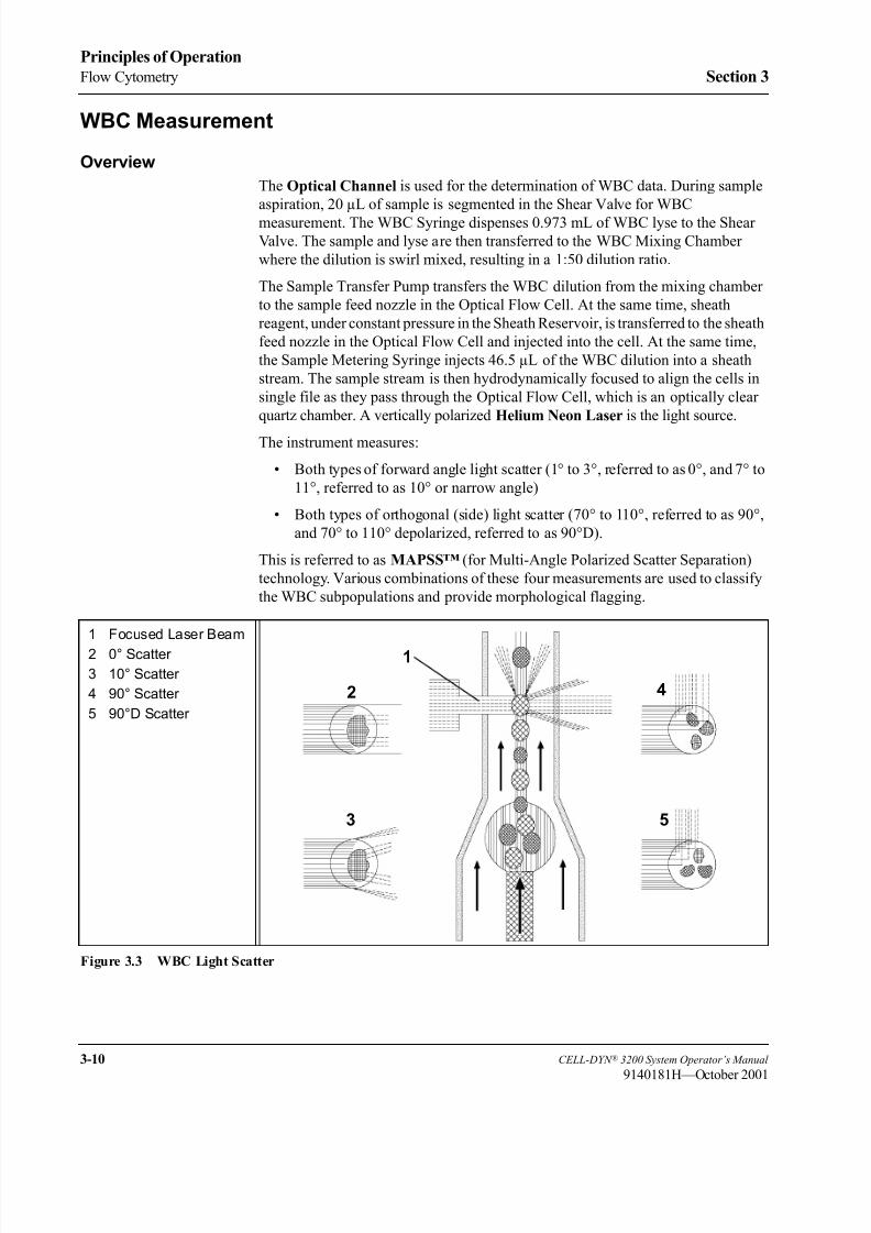
8/21/2019 Equ22-14 CellDyn3200 Op Man
http://slidepdf.com/reader/full/equ22-14-celldyn3200-op-man 108/690
3-10 CELL-DYN ® 3200 System Operator’s Manual
9140181H—October 2001
Principles of Operation
Flow Cytometry Section 3
WBC Measurement
Overview
The Optical Channel is used for the determination of WBC data. During sample
aspiration, 20 µL of sample is segmented in the Shear Valve for WBC
measurement. The WBC Syringe dispenses 0.973 mL of WBC lyse to the Shear
Valve. The sample and lyse are then transferred to the WBC Mixing Chamber
where the dilution is swirl mixed, resulting in a 1:50 dilution ratio.
The Sample Transfer Pump transfers the WBC dilution from the mixing chamber
to the sample feed nozzle in the Optical Flow Cell. At the same time, sheath
reagent, under constant pressure in the Sheath Reservoir, is transferred to the sheath
feed nozzle in the Optical Flow Cell and injected into the cell. At the same time,
the Sample Metering Syringe injects 46.5 µL of the WBC dilution into a sheath
stream. The sample stream is then hydrodynamically focused to align the cells in
single file as they pass through the Optical Flow Cell, which is an optically clear
quartz chamber. A vertically polarized Helium Neon Laser is the light source.
The instrument measures:
• Both types of forward angle light scatter (1° to 3°, referred to as 0°, and 7° to
11°, referred to as 10° or narrow angle)
• Both types of orthogonal (side) light scatter (70° to 110°, referred to as 90°,
and 70° to 110° depolarized, referred to as 90°D).
This is referred to as MAPSS™ (for Multi-Angle Polarized Scatter Separation)
technology. Various combinations of these four measurements are used to classify
the WBC subpopulations and provide morphological flagging.
Figure 3.3 WBC Light Scatter
1 Focused Laser Beam
2 0° Scatter
3 10° Scatter
4 90° Scatter
5 90°D Scatter
1
2
3 5
4

8/21/2019 Equ22-14 CellDyn3200 Op Man
http://slidepdf.com/reader/full/equ22-14-celldyn3200-op-man 109/690
CELL-DYN ® 3200 System Operator’s Manual 3-11
9140181H—October 2001
Section 3 Principles of Operation
Figure 3.3 illustrates the measurement of light scattered during the WBC optical
measurement process.
The WBC count is determined by enumerating the number of occurrences above a
hardware threshold in the 0° channel. The information from all four measurements
is used to differentiate the WBCs into five subpopulations:
Neutrophils
Lymphocytes
Monocytes
Eosinophils
Basophils
The WBC data is presented graphically as a scatterplot. It may also be presented in
two histograms at operator request.
WBC Reagent
The WBC reagent used with the CELL-DYN 3200 instrument is the CELL-DYN
WBC Lyse. It is an integral part of the WBC analysis. White blood cells diluted in
the reagent maintain cellular integrity close to their native state. The structure of
the basophils changes slightly due to the hygroscopic nature of the basophilic
granules.
The RBCs are also altered by the reagent. The osmotic pressure of the RBC is
higher than that of the reagent. Therefore, the hemoglobin in the RBC diffuses out
of the cell and water from the reagent diffuses into the cell. The cell membrane
remains intact but the RBC now has the same refractive index as the sheath, thereby
rendering it invisible to the laser.
WBC Differential
The light scatter information is graphically presented in the form of scatterplots.
(The data can also be presented in histograms, available on request.) Each cell
analyzed is represented by a dot on the scatterplot. The dots are plotted at a point
determined by the intersection of the channel information designated on the X and
Y axes. For example, if a cell falls in channel 50 on the X axis and channel 50 on
the Y axis, it is plotted at the intersecting point of the two channels.
The scatter information may be plotted in various combinations to yield different
information. The CELL-DYN 3200 uses the scatterplots to differentiate the WBCs
into five subpopulations:
Neutrophils
Eosinophils
Lymphocytes
Basophils
Monocytes

8/21/2019 Equ22-14 CellDyn3200 Op Man
http://slidepdf.com/reader/full/equ22-14-celldyn3200-op-man 110/690
3-12 CELL-DYN ® 3200 System Operator’s Manual
9140181H—October 2001
Principles of Operation
Flow Cytometry Section 3
Figure 3.4 Mononuclear-Polymorphonuclear Scatter
Mononuclear-Polymorphonuclear SeparationThe scatter information is plotted with the 90° scatter on the Y axis and the 10°
scatter on the X axis. (The 90°/10° scatterplot is shown in Figure 3.4.) Two
populations of cells are clearly seen on the display. The mononuclear cells fall in
the cluster in the lower left corner of the scatterplot and the polymorphonuclear
cells fall in the cluster above and to the right of them.
The instrument uses a dynamic threshold to determine the best separation between
the two populations. Each cell is then identified as a MONO or a POLY. Once each
cell is identified, it retains this classification no matter where it appears on other
scatterplots.
Mononuclear – Polymorphonuclear Separation
Mononuclear – Polymorphonuclear Identification
9 0 ° L o b u l a r i t y
9 0 ° L o b u l a r i t y
10° Complexity 10° Complexity

8/21/2019 Equ22-14 CellDyn3200 Op Man
http://slidepdf.com/reader/full/equ22-14-celldyn3200-op-man 111/690
CELL-DYN ® 3200 System Operator’s Manual 3-13
9140181H—October 2001
Section 3 Principles of Operation
Figure 3.5 Neutrophil-Eosinophil Scatter
Neutrophil-Eosinophil Separation
The scatter information is plotted with the 90°D scatter on the Y axis and the 90°
scatter on the X axis. (The 90°D/90° scatterplot is shown in Figure 3.5.) Only the
polymorphonuclear cells are plotted on this scatterplot. The mononuclear cells have
been identified and therefore do not interfere in the further classification of the polymorphonuclear cells.
Two populations of polymorphonuclear cells are clearly seen on the display. The
neutrophils fall in the lower of the two clusters. The eosinophils fall in the upper
cluster. The instrument uses a dynamic threshold to determine the best separation
between the two populations. Each cell is then classified as a NEUT or an EOS.
All cells scatter a certain amount of 90°D light. The eosinophils scatter more 90°D
light than any of the other cells because of the unique nature of granules they
contain. This property of the eosinophils is used to positively identify them and
thus clearly differentiate them from the neutrophil population.
9 0 ° D e p o l a r i z e d G r a n u l a r i t y
90° Lobularity90° Lobularity
9 0 ° D e p o l a r i z e d G r a n u l a r i t y
Neutrophil – EosinophilSeparation
Neutrophil – EosinophilIdentification

8/21/2019 Equ22-14 CellDyn3200 Op Man
http://slidepdf.com/reader/full/equ22-14-celldyn3200-op-man 112/690
3-14 CELL-DYN ® 3200 System Operator’s Manual
9140181H—October 2001
Principles of Operation
Flow Cytometry Section 3
Figure 3.6 Mononuclear Scatter
Mononuclear Separation
The scatter information is plotted with the 0° scatter on the Y axis and the 10°
scatter on the X axis. (The 0°/10° scatterplot is shown in Figure 3.6.) The
mononuclear cells are plotted on this scatterplot. The algorithm also uses the
orientation of the neutrophil cluster to aid in classifying the mononuclears. Three
populations of mononuclear cells are clearly seen on the display.
There are three populations of mononuclears because basophils are included in the
mononuclear cluster. Typically, basophils are granulated cells and therefore more
complex than the mononuclear cells. However, the basophilic granules are water
soluble and dissolve in the WBC Lyse reagent. Consequently, the degranulated
Basophils becomes a less complex cell that falls into the mononuclear cluster.
The lymphocytes fall in the lowest large cluster. (The small population of cells
below the lymphocytes contains particles that are unlikely to be WBCs.) The
basophils fall in the cluster above and slightly to the right of the lymphocytes. The
monocytes fall in the cluster above the lymphocytes and basophils. The instrument
uses dynamic thresholds to determine the best separation between the three main
populations. Each cell is then classified as a LYMPH, a MONO or a BASO.
10° Complexity 10° Complexity
MononuclearSeparation
MononuclearIdentification
0 ° S i z e
0 ° S i z e
8/21/2019 Equ22-14 CellDyn3200 Op Man
http://slidepdf.com/reader/full/equ22-14-celldyn3200-op-man 113/690
CELL-DYN ® 3200 System Operator’s Manual 3-15
9140181H—October 2001
Section 3 Principles of Operation
Finally, the instrument evaluates the area below the lymphocyte cluster but above
the hardware threshold (channel 23). Any particles that fall in this area are
separated from the lymphocytes by a dynamic threshold. The following cell types
may be present in this region:
NRBCs
Unlysed RBCs
Giant PLTs
PLT clumps
All particles in this region are excluded from the WBC count and the Differential.
Other Scatterplots
90°/0°
The scatter information is plotted with the 90° scatter on the Y axis and the 0°
scatter on the X axis.
90°D/0°The scatter information is plotted with the 90°D scatter on the Y axis and the 0°
scatter on the X axis.
90°D/10°
The scatter information is plotted with the 90°D scatter on the Y axis and the 10°
scatter on the X axis.
All scatterplots may be displayed and printed at operator request.
Nuclear Optical Count
Samples containing fragile WBCs are difficult to measure accurately because of
the rapid breakdown of cells during the measurement process. To obtain anaccurate WBC count, an alternate method using the HGB segment (instead of the
WBC segment) is used to measure samples containing fragile WBCs.
The HGB sample segment, after being measured in the HGB Flow Cell, is
transferred to the Optical Flow Cell instead of being sent to a waste chamber as in
normal Patient cycles. While in the HGB Flow Cell, the HGB reagent lyses the
cytoplasmic membrane of the white blood cells but allows the nuclear membrane
to remain intact. This results is a greater stability of the white cells in the sample.
The HGB segment is lysed for approximately 15 seconds before it is sent to the
Optical Flow Cell.
As the HGB segment passes through the Optical Flow Cell, the nuclei of the cells
are counted. The results of this measurement are stored in the Data Log as NOC.

8/21/2019 Equ22-14 CellDyn3200 Op Man
http://slidepdf.com/reader/full/equ22-14-celldyn3200-op-man 114/690
3-16 CELL-DYN ® 3200 System Operator’s Manual
9140181K—July 2002
Principles of Operation
Flow Cytometry Section 3
Resistant RBC
When a specimen containing resistant RBCs is run in the routine patient mode, the
lytic agent in the WBC lyse reagent may be insufficient to lyse the “resistant” cells
in the time allotted for the WBC count. Consequently, unlysed RBCs can be
erroneously included in the WBC count resulting in a falsely elevated value. When
this occurs, a significant amount of stroma will be present in the N1 region belowthe WBC dynamic threshold on the 0º/10º scatterplot.
When these type of specimens are rerun in the Resistant RBC mode, the diluted
WBC sample is held in the mixing chamber 15 seconds longer than in the routine
patient mode. This additional lysing time is used to break down (lyse) the resistant
RBC cells and prevent them from interfering with the WBC count and differential.
NOTE: A higher incidence of false positive band flags may be evident on
specimens run under the Resistant RBC specimen type.

8/21/2019 Equ22-14 CellDyn3200 Op Man
http://slidepdf.com/reader/full/equ22-14-celldyn3200-op-man 115/690
CELL-DYN ® 3200 System Operator’s Manual 3-17
9140181H—October 2001
Section 3 Principles of Operation
WBC Histograms
Figure 3.7 WBC Histograms
The CELL-DYN 3200 can present the WBC scatter information as two histograms:
NWBC-LYM-MONO (N-L-M) and Mono-Poly (M-P). The NOC (Nuclear Optical
Count) data can also be presented as a histogram. (Refer to Figure 3.7.) These
histograms may be displayed and printed at the operator’s request.
NWBC-LYM-MONO Histogram
The scatter information is plotted in a histogram format with the relative number
of cells on the Y axis and the NWBC, Lymphocyte and Monocyte size distribution
data on the X axis.
MONO-POLY Histogram
The scatter information is plotted in a histogram format with the relative number
of cells on the Y axis and the mononuclear and polymorphonuclear size
distribution data on the X axis.
NOC HistogramThe NOC data is plotted in a histogram format with the relative number of nuclei
on the Y axis and the size distribution data on the X axis.

8/21/2019 Equ22-14 CellDyn3200 Op Man
http://slidepdf.com/reader/full/equ22-14-celldyn3200-op-man 116/690
3-18 CELL-DYN ® 3200 System Operator’s Manual
9140181H—October 2001
Principles of Operation
Flow Cytometry Section 3
WBC Parameters
Figure 3.8 WBC Data and Scatterplots
The WBC data is generally displayed as depicted in Figure 3.8. All numeric and
graphic data are automatically displayed on the RUN screen in the format selected.
After the WBC scatter information has been plotted and the cells have been
classified into the five subpopulations, the algorithms then determine the WBC and
the percent of cells in each subpopulation.
Once the WBC count is determined, the absolute number of cells in eachsubpopulation is calculated by multiplying that WBC count by the percentage. The
results are expressed as follows:
WBC # x K/µL
NEU # x K/µL and %
LYM # x K/µL and %
MONO # x K/µL and %
EOS # x K/µL and %
BASO # x K/µL and %
The decimal point moves to display up to three decimal places for the absolute
number and percent.

8/21/2019 Equ22-14 CellDyn3200 Op Man
http://slidepdf.com/reader/full/equ22-14-celldyn3200-op-man 117/690
CELL-DYN ® 3200 System Operator’s Manual 3-19
9140181H—October 2001
Section 3 Principles of Operation
The WBC subpopulations are further identified by the following colors:
Neutrophils — yellow
Lymphocytes — blue
Monocytes — purple
Eosinophils — greenBasophils — white
NOTE: The basophils are displayed as white dots but appear as black dots on
color printouts.
The WBC scatter information is usually displayed in two scatterplots as shown in
Figure 3.8:
SIZE/COMPLEXITY The size (0° scatter) information is plotted on the
Y axis and the complexity (10° scatter) information
is plotted on the X axis.
GRANLRTY/LOBULARITY The granularity (90°D scatter) information is plotted
on the Y axis and the lobularity (90° scatter)information is plotted on the X axis.
WBC Flagging
Refer to the “Operational Messages and Data Flagging” subsection of this section
for WBC flagging information.
RBC/PLT Measurement
Overview
The Optical Channel is used for the determination of RBC and PLT data. During
sample aspiration, 1.67 µL of sample is segmented in the Shear Valve for RBC/PLTmeasurement.
The Diluent/Sheath Syringe dispenses 2.79 mL of diluent to the Shear Valve. The
sample and diluent are then transferred to the RBC/PLT Mixing Chamber where
the dilution is swirl mixed, resulting in a 1:1,675 dilution ratio.
The Sample Transfer Pump transfers the RBC/PLT dilution from the mixing
chamber to the sheath feed nozzle in the Optical Flow Cell. The Sample Metering
Syringe injects 24 µL of RBC/PLT dilution into the sheath stream. The sample
stream is then hydrodynamically focused to align the cells in single file as they pass
through the Optical Flow Cell, which is an optically clear quartz chamber. A
vertically polarized Helium Neon Laser is the light source.
There are 256 size channels for each of the parameters, each RBC size channel
being equivalent to 1 fL and each PLT size channel being equivalent to 0.137 fL.
The RBC parameters are calculated using 0°, 10°, and 90° sensor data, while the
PLT parameters are calculated using 0° and 10° sensor data.

8/21/2019 Equ22-14 CellDyn3200 Op Man
http://slidepdf.com/reader/full/equ22-14-celldyn3200-op-man 118/690
3-20 CELL-DYN ® 3200 System Operator’s Manual
9140181H—October 2001
Principles of Operation
Flow Cytometry Section 3
RBC Parameters
Figure 3.9 RBC Data and Histogram
All numeric and frequency size distribution data are automatically displayed on the
RUN screen in the format selected. The size distribution data for the red cells is
displayed graphically as a histogram using 0° data. The size distribution data is
plotted on the X axis. The relative number of cells is normalized and plotted on the
Y axis. The RBC data are shown in Figure 3.9.
RBC Count
The Red Blood Cell Count is directly measured, and is expressed as follows:
RBC = # x M/µL
Counts below 1.0 x M µL are displayed to three decimal places. The RBC count is
corrected for coincidence and WBC interference.
MCV
The Mean Cell Volume is the average volume of the individual red blood cells.
The MCV is derived from the RBC size distribution data on the 0°, 10°, and 90°histograms, and is expressed in femtoliters.
HCT
The Hematocrit is the ratio of red blood cells to plasma and is expressed as a
percentage of the whole blood volume. The HCT is calculated from the red blood
cell count and the mean cell volume as follows:
HCT = (RBC x MCV)/10

8/21/2019 Equ22-14 CellDyn3200 Op Man
http://slidepdf.com/reader/full/equ22-14-celldyn3200-op-man 119/690
CELL-DYN ® 3200 System Operator’s Manual 3-21
9140181H—October 2001
Section 3 Principles of Operation
MCH
The Mean Corpuscular Hemoglobin is the average amount of hemoglobin
contained in the red blood cell expressed in picograms. The MCH is calculated
from the RBC and the HGB as follows:
MCH = (HGB/RBC) x 10
MCHC
The Mean Corpuscular Hemoglobin Concentration is the ratio of the weight of
hemoglobin to the volume of the average red blood cell expressed in grams per
deciliter. MCHC is calculated from the HGB and the HCT as follows:
MCHC = (HGB/HCT) x 100
RDW
Red Cell Distribution Width is a measure of the heterogeneity of the RBC
population. The CELL-DYN 3200 reports a relative RDW equivalent to a CV in
grams per deciliter. The RDW is derived from the RBC histogram using the 20thand 80th percentiles.
RBC Flagging
Refer to the “Operational Messages and Data Flagging” subsection of this section
for RBC Flagging information.
Platelet Parameters
Events counted in the RBC/PLT dilution between floating thresholds are included
in the platelet (PLT) data, which is collected using the 0° and 10° sensors. The
lower threshold floats between 1 and 3 fL and the upper threshold floats between15 and 35 fL. If there is not enough data to determine the PLT count, the lower and
upper thresholds are set at 2 and 35 fL respectively. Once the thresholds have been
determined, the PLT count is derived from the 10° data.
Data can be displayed in two formats. It can be displayed as a scatterplot (0°/10°)
including the RBCs. Data can also be displayed as one of the following three
histograms:
PLT only using 10° data
PLT and RBC using 0° data
PLT and RBC using 10° data
PLT data are shown as a histogram of the 10° data in the following figure.
Events counted in the region below the lower threshold are usually either optical
noise or small particulate matter. Events counted in the region above the upper
threshold are counted as RBCs. If interference with either threshold region exceeds
a predetermined limit, the PLT parameters are flagged accordingly. The flags are
discussed in the last section of this chapter.
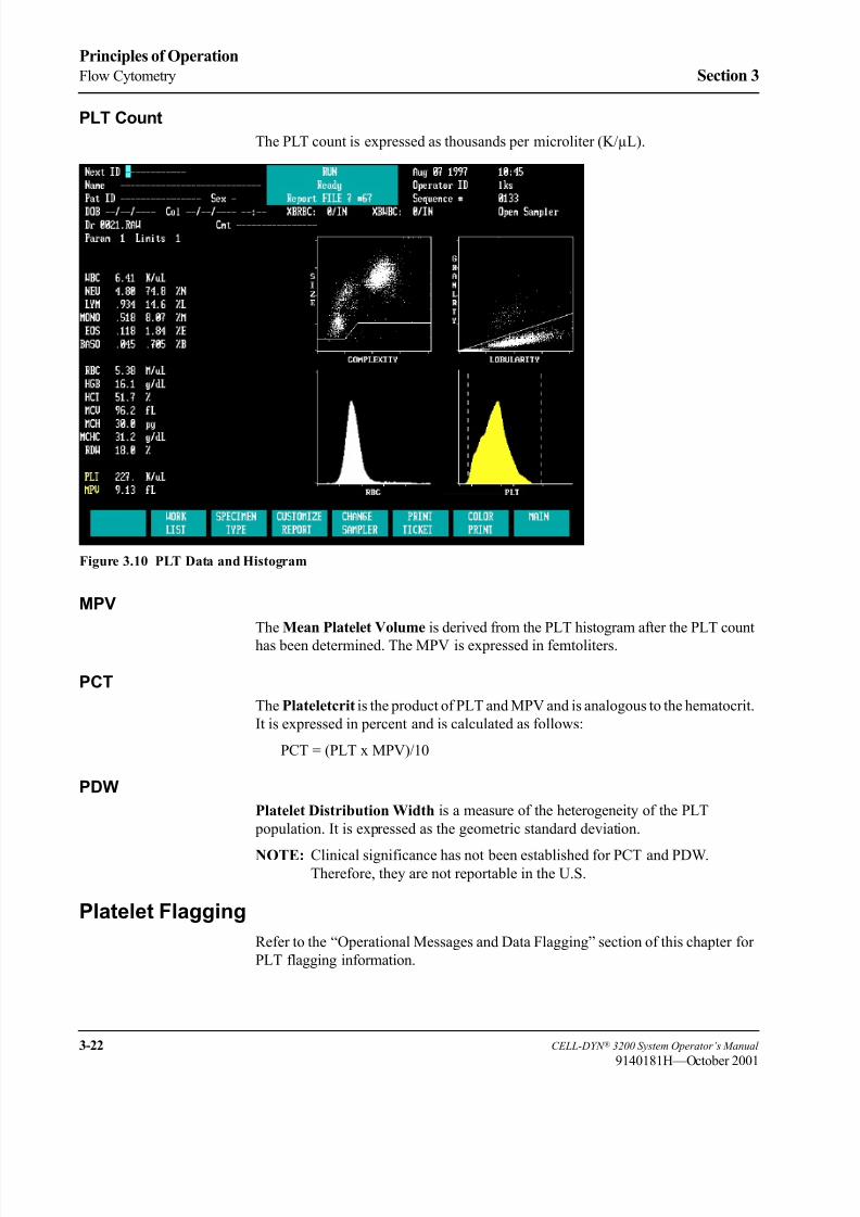
8/21/2019 Equ22-14 CellDyn3200 Op Man
http://slidepdf.com/reader/full/equ22-14-celldyn3200-op-man 120/690
3-22 CELL-DYN ® 3200 System Operator’s Manual
9140181H—October 2001
Principles of Operation
Flow Cytometry Section 3
PLT Count
The PLT count is expressed as thousands per microliter (K/µL).
Figure 3.10 PLT Data and Histogram
MPV
The Mean Platelet Volume is derived from the PLT histogram after the PLT count
has been determined. The MPV is expressed in femtoliters.
PCT
The Plateletcrit is the product of PLT and MPV and is analogous to the hematocrit.
It is expressed in percent and is calculated as follows:
PCT = (PLT x MPV)/10
PDW
Platelet Distribution Width is a measure of the heterogeneity of the PLT
population. It is expressed as the geometric standard deviation.
NOTE: Clinical significance has not been established for PCT and PDW.Therefore, they are not reportable in the U.S.
Platelet Flagging
Refer to the “Operational Messages and Data Flagging” section of this chapter for
PLT flagging information.

8/21/2019 Equ22-14 CellDyn3200 Op Man
http://slidepdf.com/reader/full/equ22-14-celldyn3200-op-man 121/690
CELL-DYN ® 3200 System Operator’s Manual 3-23
9140181M—June 2004
Section 3 Principles of Operation
Hemoglobin Measurement
Overview
The HGB channel is used for the colorimetric determination of hemoglobin.
During sample aspiration, 12 µL of sample is segmented in the Shear Valve for
HGB measurement.
Before the HGB is measured, a reference value is obtained using the
CELL-DYN 3200 Diluent/Sheath in the HGB Flow Cell. A zero or blank reading
is obtained on the diluent to provide a reference to which the sample signal is
compared. Five separate blank readings are made on the diluent. The lowest and
highest are eliminated and the remaining three are averaged to give the final HGB
reference reading.
The Diluent/Sheath Syringe dispenses 1.7 mL of diluent/sheath to the Shear Valve,
transferring the HGB segment to the HGB Mixing Chamber. The HGB Lyse
Syringe then dispenses 0.9 mL of HGB Lyse into the mixing chamber. The mixture
is swirl mixed, resulting in a 1:218 dilution ratio. The HGB lyse reagent lyses the
red blood cells, converting the hemoglobin that is released by a cyanide-free
chemical process. When the lysing action is completed, a low-energy LED in the
HGB Flow Cell, attached to the mixing chamber, measures the amount of
absorbance which is proportional to the HGB concentration.
A LED with a wavelength of 555 nm is the light source. A photodetector measures
the light that is transmitted.
Five separate HGB readings are made on each sample. The lowest and highest are
eliminated and the remaining three are averaged to give the final HGB sample reading.
After the hemoglobin readings have been made, the HGB Flow Cell is rinsed with
diluent/sheath (in the normal run mode).
The reference and sample readings are compared to determine the HGBconcentration of the sample. The HGB result is expressed in grams of hemoglobin
per deciliter of whole blood. Up to two decimal places may be displayed for
hemoglobin results less than 10.0 g/dL.
HGB Parameters
The Hemoglobin is directly measured and is expressed in grams of hemoglobin per
deciliter of whole blood.
When the WBC (WOC) is > 30 K/µL, the hemoglobin value is automatically
corrected for the WBC count. The corrected hemoglobin value is displayed on the
main RUN screen.
HGB Flagging
Refer to the “Operational Messages and Data Flagging” subsection of this section
for HGB flagging information.

8/21/2019 Equ22-14 CellDyn3200 Op Man
http://slidepdf.com/reader/full/equ22-14-celldyn3200-op-man 122/690
3-24 CELL-DYN ® 3200 System Operator’s Manual
9140181H—October 2001
Principles of Operation
Flow Cytometry Section 3
Laboratory Worksheet Screen
The LABORATORY WORKSHEET screen is provided to assist the laboratory
staff in data review and validation (refer to Figure 3.11.) This screen is for
laboratory use only. This screen displays the 5-Part Differential plus additional
parameters. The RUN and DATA LOG screens display only the 5-Part Differential.
The difference between the two formats is shown in Table 3.1 and 3.2.
NOTE: The parameters MON and LYM have an “e” after the label, indicating that
the values are estimated. MONe represents monos minus blasts. LYMe
represents reported lymphs minus variant lymphs.
Figure 3.11 Laboratory Worksheet Screen
To access the LABORATORY WORKSHEET screen, press the Page Down key on the
keyboard while the RUN menu is displayed or while the DISPLAY SPECIMEN screen
(in the DATA LOG menu) is displayed. The format is fixed and cannot be changed.
The specimen displayed on the screen is identified by the Specimen ID number and
Sequence number in the upper left corner of the screen.
To print the LABORATORY WORKSHEET screen, press the [PRINT] soft key or thePrint Screen key on the keyboard. Press [RETURN] to return to the RUN menu or
DISPLAY SPECIMEN screen (in DATA LOG menu), depending on which menu was
used to access the worksheet.
The 5-Part Differential separates WBC into 5 components: Neutrophils,
Lymphocytes, Monocytes, Eosinophils, and Basophils. The additional parameters
further separate the Neutrophils, Lymphocytes, and Monocytes into their
constituent components. Eosinophils and Basophils are the same in both tables.

8/21/2019 Equ22-14 CellDyn3200 Op Man
http://slidepdf.com/reader/full/equ22-14-celldyn3200-op-man 123/690
CELL-DYN ® 3200 System Operator’s Manual 3-25
9140181H—October 2001
Section 3 Principles of Operation
Table 3.1 5-Part Differential
Parameter Results (K/µL)
WBC 11.15
1 NEU 5.91
2 LYM 3.16
3 MONO 2.06
4 EOS 0.02
5 BASO 0.00
Table 3.2 5-Part Differential Plus Additional Parameters
Parameter Results (K/µL)
WBC 11.15
NEU 5.91
1 SEG 4.80
2 BAND 0.00
3 IG 1.11
LYM 3.16
4 LYMe 2.01
5 VARL 1.15
MONO 2.06
6 BLST 1.69
7 MONe 0.37
8 EOS 0.02
9 BASO 0.00

8/21/2019 Equ22-14 CellDyn3200 Op Man
http://slidepdf.com/reader/full/equ22-14-celldyn3200-op-man 124/690
3-26 CELL-DYN ® 3200 System Operator’s Manual
9140181H—October 2001
Principles of Operation
Flow Cytometry Section 3
NOTES

8/21/2019 Equ22-14 CellDyn3200 Op Man
http://slidepdf.com/reader/full/equ22-14-celldyn3200-op-man 125/690
CELL-DYN ® 3200 System Operator’s Manual 3-27
9140181H—October 2001
Section 3 Principles of Operation
Operational Messages and Data Flagging
IntroductionOperational messages and data flags appear on the RUN screen, on printed reports
and can be transmitted to a laboratory computer system. The CELL-DYN 3200
monitors instrument conditions and data criteria that may affect the displayed
results and these messages and flags are used to alert the operator. Instructions for
interpreting all flags, and numeric, scatter and histogram data should be incorporated
into the laboratory’s procedure and used to determine the need for further action and/
or review of results. Messages are divided into the following categories:
Instrument Messages:
Fault Conditions
Status Conditions
Parameter Flagging Messages:
Dispersional Data Alerts
Suspect Parameter Flags
Suspect Population Flags
Interpretive Messages
Detailed descriptions of the messages in each of the categories are given in this
section.
Instrument Fault and Status Conditions
The Instrument Fault and Status conditions are discussed in Tables 10.1 through
Table 10.4 in Section 10: Troubleshooting and Diagnostics; Subsection:
Troubleshooting Guide. These messages are displayed when the instrument
detects an inappropriate condition during specimen processing. When necessary,
data is suppressed. When any of these messages are displayed, refer to the
Troubleshooting Guide for assistance. Follow the instructions given and take the
appropriate corrective action. When the problem is corrected, repeat the specimen.

8/21/2019 Equ22-14 CellDyn3200 Op Man
http://slidepdf.com/reader/full/equ22-14-celldyn3200-op-man 126/690
3-28 CELL-DYN ® 3200 System Operator’s Manual
9140181M—June 2004
Principles of Operation
Operational Messages and Data Flagging Section 3
Cell Populations and Flagging
Interfering Substances
It is important to note that there are commonly occurring interfering substances that
can affect the results reported by hematology analyzers. While the
CELL-DYN 3200 has been designed to detect and flag many of these substances,
it may not always be possible to do so. The following indicates some of the
substances that may interfere with each of the listed parameters.
WBC: Fragile WBCs, neutrophil aggregates, lytic-resistant RBCs, NRBCs, PLT
clumps, cryofibrinogen, cryoglobulin, paraproteins
RBC: Elevated WBC count, increased numbers of giant PLTs, auto-
agglutination, in vitro hemolysis
HGB: Elevated WBC count, increased plasma substances (triglycerides,
bilirubin, in vivo hemolysis), lytic-resistant RBCs
MCV: Elevated WBC count, hyperglycemia, in vitro hemolysis, increased
numbers of giant PLTs
PLT: WBC fragments, in vitro hemolysis, microcytic RBCs, cryofibrinogen,
cryoglobulins, PLT clumping, increased numbers of giant PLTs
For additional information on interfering substances, refer to the table provided in
Appendix C.
For a detailed description of the flags that are generated, refer to Section 3:
Principles of Operation; Subsection: Operational Messages and Data Flagging .
Fragile WBCs
Typically, fragile WBCs are abnormal lymphocytes that are present in chronic
lymphocytic leukemia (CLL) and are the “smudge cells” that appear when the
blood smear is made.
When processing samples in the Patient mode (Patient is selected as the Specimen
Type in the RUN screen), if fragile WBCs are present the WBC (WOC) count may
be abnormally low due to the gradual destruction of the cytoplasmic membrane of
these fragile cells by the lysing agents during the Run cycle.
When the FWBC flag displays, repeat the specimen using Specimen Type Fragile
WBC. This selection uses the HGB sample dilution containing intact WBC nuclei.
This Nuclear Optical Count (NOC) provides a more accurate WBC count when
fragile WBCs are present.

8/21/2019 Equ22-14 CellDyn3200 Op Man
http://slidepdf.com/reader/full/equ22-14-celldyn3200-op-man 127/690
CELL-DYN ® 3200 System Operator’s Manual 3-29
9140181M—June 2004
Section 3 Principles of Operation
Lyse-Resistant RBCs
Resistant RBCs are red blood cells which contain abnormalities or whose
membranes have been altered, making them more resistant to the lysing process.
When running samples in the Patient mode, the hypo-osmotic lysing ability of the
WBC Lyse reagent is usually insufficient to lyse any lyse-resistant RBC cells, if
present, in the time allotted for the WBC count. Consequently, the unlysed RBCs
may be erroneously included in the WBC count, resulting in a falsely elevated
count.
In normal patient samples, lyse-resistant RBCs are either absent or their number is
negligible. In patient samples with a significant number of lyse-resistant RBCs,
usually there is also a significant amount of stroma interference present in the N1
region below the dynamic WOC threshold on the 0º / 10º scatterplot.
RRBC/NRBC Flag
When this type of interference is detected, the RRBC/NRBC (Resistant RBC/
Nucleated RBC) flag is displayed. This flag alerts the operator to potential
interference by lytic-resistant RBCs, NRBCs or a combination of the two. It also
alerts the operator to run the specimen in the Resistant RBC Specimen Type. When
Resistant RBC Specimen Type is selected, the WBC lyse time is extended to allow
for complete lysing of lytic-resistant RBCs in order to obtain an accurate WBC
(WOC) result. The Resistant RBC Specimen Type also provides a NOC result.
If the NOC result and the WOC result are discrepant in Resistant RBC Specimen
Type, NRBCs may be present. A stained smear should be reviewed to confirm the
presence of NRBCs and to quantify them according to your laboratory’s procedure.
(Sickle cells or target cells may indicate that NRBCs are also present.) If correction
of the WBC is required, the NOC value should be corrected and compared to the
WOC value from the RRBC Specimen Type. If the corrected NOC confirms the
WOC result, the WOC can be reported. If the values are discrepant, the operatorshould follow the laboratory’s procedure for obtaining an accurate WBC result.

8/21/2019 Equ22-14 CellDyn3200 Op Man
http://slidepdf.com/reader/full/equ22-14-celldyn3200-op-man 128/690
3-30 CELL-DYN ® 3200 System Operator’s Manual
9140181M—June 2004
Principles of Operation
Operational Messages and Data Flagging Section 3
Parameter Flagging Messages
Table 3.3 summarizes all of the parameter flagging messages by parameter and
category.
Table 3.3 Parameter Flagging Messages
Parameter Dispersional Data AlertsSuspect
Parameter Flags
Suspect
Population Flags
Interpretive
Messages
WBC
Result displays in yellow if
below lower limit
Result displays in purple if
above upper limit
Result underlined on graphics
printout when limits exceeded
Result underlined on blank
ticket when limits exceeded
Result marked with asterisk (*)on preprinted ticket when
results exceeded
WBC NWBC
FWBC
NRBC
RRBC
Leukopenia
Leukocytosis
Differential
NEU
LYM
MONO
EOS
BASO
Same as WBC
DFLT (NLMEB)
DFLT (NE)
DFLT (LM)
DFLT (B)
DFLT
BAND
IG
BLAST
VAR LYM
Neutropenia
Neutrophilia
Lymphopenia
Lymphocytosis
Monocytosis
Eosinophilia
Basophilia
RBC
HGB
MCV
RDW
Same as WBC
RBC MORPH Anemia
Polycythemia
Microcytic RBC
Macrocytic RBC
Hypochromic
Hyperchromic
Anisocytosis
PLT
MPVSame as WBC
LRI
URI
LURI
The MPV value
may be suppressed
(not displayed
or printed).
Thrombocytopenia
Thrombocytosis
Microcytic PLT
Macrocytic PLT

8/21/2019 Equ22-14 CellDyn3200 Op Man
http://slidepdf.com/reader/full/equ22-14-celldyn3200-op-man 129/690
CELL-DYN ® 3200 System Operator’s Manual 3-31
9140181M—June 2004
Section 3 Principles of Operation
Dispersional Data Alerts
These alerts are triggered by the numeric limits entered into the six Patient Limit
Sets (see Section 5: Operating Instructions; Subsection: Set Up Instructions for
an explanation) or taken from the instrument’s preset linearity limits. If results for a
parameter exceed these limits, they are flagged on the screen and on the report.
Dispersional alerts are displayed or printed as follows:
Screen display: Result below lower limit shown in yellow
Result above upper limit shown in purple
Linearity Exceeded: Result displayed as >>>
NOTE: When the WBC result exceeds the linearity
(>>>) the HGB result is displayed as <<< to
indicate possible interference with the HGB due
to the elevated WBC result.
Graphic Report: Results outside limits are underlined
Blank Ticket: Results outside limits are underlinedPreprinted Ticket: Results outside limits are marked with an asterisk
Specimens with results that exceed the linearity should be diluted with diluent/
sheath according to the laboratory’s procedure and repeated. (Be sure to correct the
results for the dilution factor used.)
NOTE: MCV, MCH, MCHC and MPV are unaffected by dilution and do not
require correction.
Dispersional Data Alerts
It is suggested that one Patient Limit Set be used to enter instrument-specific
laboratory action limits. If the Interpretive Report option is enabled, theInterpretive messages, such as leukocytosis, anemia, thrombocytopenia, etc., will
be displayed when a result falls outside the appropriate limit. A result that falls
outside a laboratory action limit can also indicate the need for the operator to
follow a laboratory protocol, such as repeating the sample, notifying the physician
or performing a smear review. In cases where a cellular abnormality is present that
alters cellular morphology to the point that the cells do not fit the criteria used by
the instrument to generate a flag, dispersional data alerts may be the only flag(s)
that will alert the operator to a potentially erroneous result.
Suspect Parameter Flags
These flags are generated after the instrument evaluates the measured data for a
particular parameter or group of parameters. The result may be suspect due tointerfering substances or the inability of the instrument to measure a particular
parameter due to a sample abnormality.
8/21/2019 Equ22-14 CellDyn3200 Op Man
http://slidepdf.com/reader/full/equ22-14-celldyn3200-op-man 130/690
3-32 CELL-DYN ® 3200 System Operator’s Manual
9140181M—June 2004
Principles of Operation
Operational Messages and Data Flagging Section 3
Introduction to WBC Flagging
There are five WBC parameter flags: WBC, DFLT (NLMEB), DFLT (NE), DFLT
(LM), and DFLT (B). The following WBC population flags may be displayed:
NWBC, FWBC, NRBC, RRBC, BAND, IG, BLAST, VAR LYM. If any of the
WBC population or parameter flags is displayed, the message SUSPECT is
displayed under and to the right of the Limits field on the RUN and LABORATORYWORKSHEET screens. This message also appears on printouts.
WBC Descriptors
The WBC Descriptors (WOC and NOC) are included on the display screen and
printout to provide additional information about the reported WBC value. If there
is a clinically significant difference between the two results in the QC and Resistant
RBC specimen types, the instrument will select the appropriate result and display
a descriptor in parentheses next to the WBC value.
NOTE: In the Fragile WBC specimen types, the NOC value is always selected.

8/21/2019 Equ22-14 CellDyn3200 Op Man
http://slidepdf.com/reader/full/equ22-14-celldyn3200-op-man 131/690
CELL-DYN ® 3200 System Operator’s Manual 3-33
9140181M—June 2004
Section 3 Principles of Operation
Data Flagging
Table 3.4 Specimen Types
Patient Specimen Type
Descriptor/Flag Cause Suggested Action
NWBC When stroma interference is high and
there is no declining WOC kinetic rate
A. Review smear for platelet clumps, giant
platelets or low levels of NRBCs and follow
your laboratory’s review criteria.
B. If no other suspect parameter flags are
present, the WBC and differential may be
reported.
WBC
NRBC/RRBC
Stroma interference is high and a
declining WOC kinetic rate is detected.
A. Repeat in Resistant RBC mode.
B. If flag persists, review for presence of
NRBCs and verify Lymph value. Confirm WBC
count by alternate method.
WBC
VAR LYMPH
FWBC
DFLT (NLMEB)
1. Stroma interference is low but a
declining WOC kinetic rate is detected.
2. Stroma interference is low and there is
no declining WOC kinetic rate, but
WOC>4.1 K/uL and LYM%>80%.
A. Repeat in FWBC mode. NOC result will be
reported as WBC result.
B. Review smear to confirm lymph count and
presence of fragile WBCs.
DFLT(NLMEB)* One or more of the following conditions
are true:
1. Fragile cells may be present. (When
the FWBC flag is triggered, DFLT
(NLMEB) flag is always set.)
2. An abnormally low number of cells tocalculate differential.
3. The mono-poly cut has too much
interference.
NOTE: There are four different DFLT
flags: (NLMEB), (NE), (LM), and
(B).
(N=Neutrophils, L=Lymphocytes,
M=Monocytes, E=Eosinophils,
B=Basophils)
A. If the DFLT (NLMEB) flag is accompanied
with the FWBC flag, repeat in the FWBC
mode.
B. Review scatterplot for clear separation of
cell cluster.
C. Review a stained smear to verify thedifferential values.
DFLT (NE)*
or DFLT (LM)*
or DFLT (B)*
The letters in parentheses indicate which
WBC subpopulation or group of
subpopulations is suspect. The DFLTflag may be due to the presence of
abnormal cell clusters that the
instrument cannot reliably discriminate
among WBC subpopulations. Thus, a
default threshold is selected.
A. Review scatterplot for clear separation of
cell cluster.
B. Review a stained smear to verify the
differential values.
* These flags are also triggered in the RRBC, FWBC, and QC specimen types. Refer to the Patient Specimen
Type table for the cause and suggested action.

8/21/2019 Equ22-14 CellDyn3200 Op Man
http://slidepdf.com/reader/full/equ22-14-celldyn3200-op-man 132/690
3-34 CELL-DYN ® 3200 System Operator’s Manual
9140181M—June 2004
Principles of Operation
Operational Messages and Data Flagging Section 3
Patient Specimen Type
Descriptor/Flag Cause Suggested Action
BAND* The BAND flag is triggered if any of thefollowing conditions are met:
1. The CV of the neutrophil cluster on the
0° axis exceeds expected criteria.
2. BAND% > 12.5% of the total WBC
count.
3. The ratio of suspected bands to
mature neutrophils is >50%
Review a stained smear for the presence ofbands and follow your laboratory’s review
criteria.
NOTE: When bands are present, they are
included in the total neutrophil count.
IG* The IG flag is triggered if the following
condition is met:
The count in the region of scatter where
IGs are typically located is ≥ 3% of the
total WBC count
Review a stained smear for the presence of
immature granulocytes and follow your
laboratory’s review criteria.
NOTE: When IGs are present, they areincluded in the total neutrophil count.
BLAST* The BLAST flag is triggered if the
following condition is met:
The count in the region of scatter where
Blasts are typically located is > 1% of the
total WBC count
Review a stained smear for the presence of
blasts and follow your laboratory’s review
criteria.
NOTE: When blasts are present, they are
included in the monocyte count.
VAR LYM* 1. When the FWBC flag is triggered, VAR
LYM flag is always set.
2. Any of the following attributes fail to
meet expected criteria:
1) Position of the lymphocyte cluster on
the scatter plot.
2) Ratio between lymphocytes and other
WBC subpopulations
3) Lymphocyte count (absolute or %)
Review a stained smear for the presence of
variant lymphocytes and follow yourlaboratory’s review criteria.
NOTE: When variant lymphocytes are
present, they are included in the
lymphocyte count.
NOTE: This flag may be displayed singly or in
combination with the blast flag. If the
flag is displayed with the blast flag, it
is displayed as VLYM/BLAST.
RBC MORPH* One or more of the following parameters
exceeds expected limits:
MCV < 80fL or >100fL
MCH < 25pg or >34pg
MCHC < 29g/dL or >37g/dL
RDW >18.5%
1. Review a stained smear for abnormal RBC
or PLT morphology and follow your
laboratory's review criteria.2. If NRBCs or RRBCs are suspected to be
present, run the specimen in the NOC mode.
* These flags are also triggered in the RRBC, FWBC, and QC specimen types. Refer to the Patient Specimen
Type table for the cause and suggested action.
Table 3.4 Specimen Types (Continued)
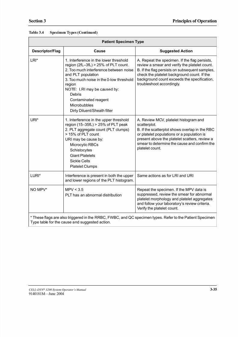
8/21/2019 Equ22-14 CellDyn3200 Op Man
http://slidepdf.com/reader/full/equ22-14-celldyn3200-op-man 133/690
CELL-DYN ® 3200 System Operator’s Manual 3-35
9140181M—June 2004
Section 3 Principles of Operation
Patient Specimen Type
Descriptor/Flag Cause Suggested Action
LRI* 1. Interference in the lower thresholdregion (2fL–3fL) > 25% of PLT count.
2. Too much interference between noise
and PLT population
3. Too much noise in the 0-low threshold
region
NOTE: LRI may be caused by:
Debris
Contaminated reagent
Microbubbles
Dirty Diluent/Sheath filter
A. Repeat the specimen. If the flag persists,review a smear and verify the platelet count.
B. If the flag persists on subsequent samples,
check the platelet background count. If the
background count exceeds the specification,
troubleshoot accordingly.
URI* 1. Interference in the upper threshold
region (15–35fL) > 25% of PLT peak
2. PLT aggregate count (PLT clumps)
> 15% of PLT count
URI may be cause by:
Microcytic RBCs
Schistocytes
Giant Platelets
Sickle Cells
Platelet Clumps
A. Review MCV, platelet histogram and
scatterplot.
B. If the scatterplot shows overlap in the RBC
or platelet populations or a population is
present above the platelet scatters, review a
smear to determine the cause and confirm the
platelet count.
LURI* Interference is present in both the upperand lower regions of the PLT histogram. Same actions as for LRI and URI
NO MPV* MPV < 3.5
PLT has an abnormal distribution
Repeat the specimen. If the MPV data is
suppressed, review the smear for abnormal
platelet morphology and platelet aggregates
and follow your laboratory’s review criteria.
Verify the platelet count.
* These flags are also triggered in the RRBC, FWBC, and QC specimen types. Refer to the Patient Specimen
Type table for the cause and suggested action.
Table 3.4 Specimen Types (Continued)
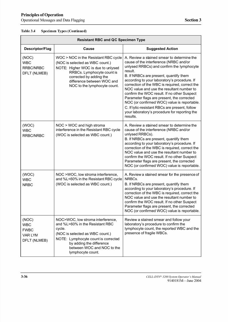
8/21/2019 Equ22-14 CellDyn3200 Op Man
http://slidepdf.com/reader/full/equ22-14-celldyn3200-op-man 134/690
3-36 CELL-DYN ® 3200 System Operator’s Manual
9140181M—June 2004
Principles of Operation
Operational Messages and Data Flagging Section 3
Resistant RBC and QC Specimen Type
Descriptor/Flag Cause Suggested Action
(NOC)
WBC
RRBC/NRBC
DFLT (NLMEB)
WOC > NOC in the Resistant RBC cycle
(NOC is selected as WBC count.)
NOTE: Higher WOC is due to unlysed
RRBCs. Lymphocyte count is
corrected by adding the
difference between WOC and
NOC to the lymphocyte count.
A. Review a stained smear to determine thecause of the interference (NRBC and/or
unlysed RRBCs) and confirm the lymphocyte
result.
B. If NRBCs are present, quantify them
according to your laboratory’s procedure. If
correction of the WBC is required, correct the
NOC value and use the resultant number to
confirm the WOC result. If no other Suspect
Parameter flags are present, the corrected
NOC (or confirmed WOC) value is reportable.
C. If lytic-resistant RBCs are present, follow
your laboratory’s procedure for reporting theresults.
(WOC)
WBC
RRBC/NRBC
NOC > WOC and high stroma
interference in the Resistant RBC cycle
(WOC is selected as WBC count.)
A. Review a stained smear to determine the
cause of the interference (NRBC and/or
unlysed RRBCs).
B. If NRBCs are present, quantify them
according to your laboratory’s procedure. If
correction of the WBC is required, correct the
NOC value and use the resultant number to
confirm the WOC result. If no other Suspect
Parameter flags are present, the corrected
NOC (or confirmed WOC) value is reportable.
(WOC)
WBC
NRBC
NOC >WOC, low stroma interference,
and %L<60% in the Resistant RBC cycle
(WOC is selected as WBC count.)
A. Review a stained smear for the presence of
NRBCs.
B. If NRBCs are present, quantify them
according to your laboratory’s procedure. If
correction of the WBC is required, correct the
NOC value and use the resultant number to
confirm the WOC result. If no other Suspect
Parameter flags are present, the corrected
NOC (or confirmed WOC) value is reportable.
(NOC)
WBCFWBC
VAR LYM
DFLT (NLMEB)
NOC>WOC, low stroma interference,
and %L>60% in the Resistant RBCcycle.
(NOC is selected as WBC count.)
NOTE: Lymphocyte count is corrected
by adding the difference
between WOC and NOC to the
lymphocyte count.
Review a stained smear and follow your
laboratory’s procedure to confirm thelymphocyte count, the reported WBC and the
presence of fragile WBCs.
Table 3.4 Specimen Types (Continued)

8/21/2019 Equ22-14 CellDyn3200 Op Man
http://slidepdf.com/reader/full/equ22-14-celldyn3200-op-man 135/690
CELL-DYN ® 3200 System Operator’s Manual 3-37
9140181M—June 2004
Section 3 Principles of Operation
NOTE: Resistant RBC, QC Specimen Type and Fragile WBC Specimen Type
have additional flags listed in the Patient Specimen Type section of
Table 3.4.
Fragile WBC Specimen Type
Descriptor/Flag Cause Suggested Action
(NOC)
FWBC
VAR LYM
DFLT (NLMEB)
In the Fragile WBC cycle, the FWBC flagis always displayed along with the DFLT
(NLMEB) flag.
(NOC is selected as WBC count.)
Review smear to confirm Lymph count andpresence of fragile WBCs.
Table 3.4 Specimen Types (Continued)

8/21/2019 Equ22-14 CellDyn3200 Op Man
http://slidepdf.com/reader/full/equ22-14-celldyn3200-op-man 136/690
3-38 CELL-DYN ® 3200 System Operator’s Manual
9140181M—June 2004
Principles of Operation
Operational Messages and Data Flagging Section 3
Interpretive Messages
Interpretive messages appear only on the graphics report and are generated when
the numeric limits entered in the Patient Limit Sets are exceeded. (see Section 5:
Operating Instructions; Subsection: Set Up Instructions for an explanation).
These messages are printed only when the Interpretive Report option is selected on
the CUSTOMIZE REPORT SCREEN. The Interpretive messages are summarized below.
WBC Messages
RBC Messages
PLT Messages
Message Cause
Leukopenia result exceeds the lower limit for WBC
Leukocytosis result exceeds the upper limit for WBC
Neutropenia result exceeds the lower limit for Neutrophil absolute
number
Neutrophilia result exceeds the upper limit for Neutrophil absolute
number
Lymphopenia result exceeds the lower limit for Lymphocyte
absolute number
Lymphocytosis result exceeds the upper limit for Lymphocyte
absolute number
Monocytosis result exceeds the upper limit for Monocyte absolute
number
Eosinophilia result exceeds the upper limit for Eosinophil absolute
number
Basophilia result exceeds the upper limit for Basophil absolute number
Message Cause
Anemia result exceeds the lower limit for RBCs
Polycythemia result exceeds the upper limit for RBCs
Microcytic RBC result exceeds the lower limit for MCV
Macrocytic RBC result exceeds the upper limit for MCV
Hypochromic result exceeds the lower limit for MCHC
Hyperchromic result exceeds the upper limit for MCHC
Anisocytosis result exceeds the upper limit for RDW
Message Cause
Thrombocytopenia result exceeds the lower limit for PLTs
Thrombocytosis result exceeds the upper limit for PLTs
Microcytic PLT result exceeds the lower limit for MPV
Macrocytic PLT result exceeds the upper limit for MPV
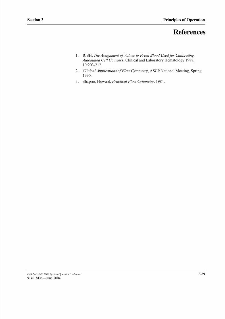
8/21/2019 Equ22-14 CellDyn3200 Op Man
http://slidepdf.com/reader/full/equ22-14-celldyn3200-op-man 137/690
CELL-DYN ® 3200 System Operator’s Manual 3-39
9140181M—June 2004
Section 3 Principles of Operation
References
1. ICSH, The Assignment of Values to Fresh Blood Used for Calibrating Automated Cell Counters, Clinical and Laboratory Hematology 1988,
10:203-212.
2. Clinical Applications of Flow Cytometry, ASCP National Meeting, Spring
1990.
3. Shapiro, Howard, Practical Flow Cytometry, 1984.

8/21/2019 Equ22-14 CellDyn3200 Op Man
http://slidepdf.com/reader/full/equ22-14-celldyn3200-op-man 138/690
3-40 CELL-DYN ® 3200 System Operator’s Manual
9140181M—June 2004
Principles of Operation
References Section 3
NOTES

8/21/2019 Equ22-14 CellDyn3200 Op Man
http://slidepdf.com/reader/full/equ22-14-celldyn3200-op-man 139/690
CELL-DYN ® 3200 System Operator’s Manual 4-1
9140181M—June 2004
Section 4 Performance Characteristics and Specifications
Section 4 Performance Characteristics and Specifications
Overview
This section is a collection of detailed information about the CELL-DYN 3200
System.
Included in this section are:
• Physical Specifications
• Operational Specifications
• Bar Code Specifications
• Measurement Specifications
• Performance Specifications
• Performance Characteristics
• Sample Loader Specifications
Specifications for the Host Interface (List Number 06H71-01) are not included in
this section but can be ordered by calling Abbott Diagnostics Customer Service at
1 (877) 4ABBOTT or 1 (877) 422-2688.
8/21/2019 Equ22-14 CellDyn3200 Op Man
http://slidepdf.com/reader/full/equ22-14-celldyn3200-op-man 140/690
4-2 CELL-DYN ® 3200 System Operator’s Manual
9140181H—October 2001
Performance Characteristics and Specifications
Overview Section 4
NOTES

8/21/2019 Equ22-14 CellDyn3200 Op Man
http://slidepdf.com/reader/full/equ22-14-celldyn3200-op-man 141/690
CELL-DYN ® 3200 System Operator’s Manual 4-3
9140181H—October 2001
Section 4 Performance Characteristics and Specifications
System Specifications
Physical SpecificationsTable 4.1 and Table 4.2 contain physical specifications for both the
CELL-DYN 3200SL and CS models.
Table 4.1 Instrument Dimensions
Analyzer SL Analyzer CSDisplay
Monitor
Ticket Printer
(Dot Matrix)
Graphics
Printer
(Color Bubble
Jet)
Height 19" (48.2 cm) 19" (48.2 cm) 15" (38.1 cm) 6" (15.2 cm) 7.2" (18.3 cm)
Width 32.8" (83.3 cm) 32.8" (83.3 cm) 14" (35.5 cm) 16.5" (41.9 cm) 16.1" (40.9 cm)
Depth 29.3" (74.4 cm) 23.3" (59.2 cm) 16" (40.6 cm) 14.5" (36.8 cm) 9.9" (25.1 cm)
Weight 232 lb (105.5 kg) 214 lb (97.3 kg) 30 lb (13.6kg) 16.5 lb (7.5 kg) 9.9 lb (4.5 kg)
Table 4.2 Dimensions After Packaging for Shipment
Analyzer SL Analyzer CSDisplay
Monitor
Ticket Printer
(Dot Matrix)
Graphics
Printer
(Color Bubble
Jet)
Height 38" (96.5 cm) 38" (96.5 cm) 20" (50.8 cm) 9.5" (24 cm) 12" (30.5 cm)
Width 34" (86.3 cm) 34" (86.3 cm) 18" (45.7 cm) 21" (53 cm) 19.5" (49.5 cm)
Depth 31" (78.7 cm) 31" (78.7 cm) 18" (45.7 cm) 18.5" (46 cm) 14.8" (37.6 cm)
Weight 273 lb (124 kg) 255 lb (116 kg) 37.5 lb (17 kg) 21 lb (9.5 kg) 16.4 lb (7.4 kg)

8/21/2019 Equ22-14 CellDyn3200 Op Man
http://slidepdf.com/reader/full/equ22-14-celldyn3200-op-man 142/690
4-4 CELL-DYN ® 3200 System Operator’s Manual
9140181K—July 2002
Performance Characteristics and Specifications
System Specifications Section 4
Power Specifications
Table 4.3 shows the power requirements for both the CELL-DYN 3200 SL and CS
models.
Consumption
Analyzer: 900 watts
Monitor: 156 watts
Graphics Printer: 60 watts1116 watts maximum (3810 BTU per hour)
Transport and Storage Specifications
There are no specific environmental conditions for transport or storage.
Table 4.3 Power Specifications
Analyzer Input Requirements
Module Voltage Frequency Max Current BTU/Hr
Analyzer 110 VAC ± 10%
120 VAC ± 10%
220 VAC ± 10%
240 VAC ± 10%
50/60 ± 3Hz
50/60 ± 3Hz
50/60 ± 3Hz
50/60 ± 3Hz
6 amps
6 amps
3 amps
3 amps
1945
1945
1945
1945
Analyzer &
Sample Loader
110 VAC ± 10%
120 VAC ± 10%
220 VAC ± 10%
240 VAC ± 10%
50/60 ± 3Hz
50/60 ± 3Hz
50/60 ± 3Hz
50/60 ± 3Hz
6 amps
6 amps
3 amps
3 amps
1945
1945
1945
1945
Monitor 100–240 VAC 50/60 Hz 1.3 amps
Printer 120 VAC ± 10%
220 - 260 VAC
50/60 Hz 0.5 amps 205

8/21/2019 Equ22-14 CellDyn3200 Op Man
http://slidepdf.com/reader/full/equ22-14-celldyn3200-op-man 143/690
CELL-DYN ® 3200 System Operator’s Manual 4-5
9140181K—July 2002
Section 4 Performance Characteristics and Specifications
Operational Specifications
Operating Environment
Indoor Use
Laboratory Temperature 15–30°C (59°–86°F)
Relative Humidity 20–80%, RHNC
Startup/Shutdown Times
Auto-Startup (from STANDBY) Approximately 5.0 minutes
Auto-Startup (from power OFF) Approximately 7.0 minutes*
Shutdown (to STANDBY) 10 minutes
* The laser requires a 15 minute warm up time. If the power has been OFF
longer than 5 minutes, wait 10 minutes after the Auto-Startup cycle is
complete before processing samples.
Run Cycle Times
Table 4.4 shows the average Run cycle times for different specimen types run in
the Open and Closed Modes on the CS and SL models.
Approximate Aspiration Volumes (Whole Blood)
Open mode 150 µL
Closed mode 240 µL
Batch Size
Up to 50 tubes per batch
Table 4.4 Instrument Average Run Cycle Times
CS and SL - ModelsCycle Times:
Ready to Ready
OPEN
Patient 51 seconds
QC, Fragile WBC 95 seconds
Resistant RBC 93 seconds
CLOSED
Patient 60 seconds
QC, Fragile WBC,
Resistant RBC103 seconds

8/21/2019 Equ22-14 CellDyn3200 Op Man
http://slidepdf.com/reader/full/equ22-14-celldyn3200-op-man 144/690
4-6 CELL-DYN ® 3200 System Operator’s Manual
9140181H—October 2001
Performance Characteristics and Specifications
System Specifications Section 4
Throughput
Table 4.5 contains sample throughput information for the CELL-DYN 3200SL and
CS.
NOTE: Maximum throughput may be achieved with normal samples that do not
generate any instrument operational messages.
Collection Tube and Sample Volume
13-mm diameter x 75-mm high collection tubes
• Minimum sample volume (SL Models) > 1.5 mL
• Minimum sample volume (CS Models) > 1.5 mL
• Maximum sample volume ~ 3 mL (Sample Loader)
NOTE: The sample volume in the tube must be within the specified limits for
adequate mixing and sampling.
Bar Code Specifications — CELL-DYN 3200SL
Bar Code Format
The following formats with or without check digits are acceptable:
• Code 39
• Code 128 (check digit only)
• Interleaved 2 of 5
• Codabar
Bar Code Label Specifications
Refer to Appendix A and ANSI specifications for complete information on bar
code label formats, check digits and specifications.
Table 4.5 Sample Throughput (Patient Mode)
CS Model Samples Per Hour
Open 71
Closed 62
SL Model Samples Per Hour
Open 71
Closed 58

8/21/2019 Equ22-14 CellDyn3200 Op Man
http://slidepdf.com/reader/full/equ22-14-celldyn3200-op-man 145/690
CELL-DYN ® 3200 System Operator’s Manual 4-7
9140181H—October 2001
Section 4 Performance Characteristics and Specifications
Measurement Specifications — CELL-DYN 3200SL and CS
Measurement Channels
Laser optics for WBC and RBC/PLT
Hemoglobin AbsorbanceReticulocyte %
WBC (WOC)
Method Laser light scatter
Light source Vertically polarized 5–10 mW helium-neon laser
Wave length 632.8 nm
Dilution 1:50 of blood in WBC lyse
Data Collection Four angles measured: 0°, 10°, 90°, and 90° depolarized. Data
collected in 256 channels for each angle of light scatter
WBC (NOC)
Method Laser light scatter
Light source Vertically polarized 5–10 mW helium-neon laser
Wave length 632.8 nm
Dilution 1:218 of blood in diluent/sheath and HGB Lyse
Data Collection Four angles measured: 0°, 10°, 90°, and 90° depolarized. Data
collected in 256 channels for each angle of light scatter
RBCs and PLTs
Method Laser light scatter Light source Vertically polarized 5–10 mW helium-neon laser
Wave length 632.8 nm
Dilution 1:1,675 of blood in diluent/sheath
Data Collection Three angles measured: 0°, 10°, and 90°. Data collected in 256
channels for each angle of light scatter
HGB
Method Modified methemoglobin
Light Source LED, wavelength: 555 nm
Wavelength 555 nm
Dilution 1:218 of blood in diluent/sheath and HGB Lyse
Data Collection Five absorbance readings for the blank, lowest and highest
readings eliminated. The three remaining absorbance readings
are averaged for the HGB reference. Five absorbance readings
for the sample, lowest and highest readings eliminated. The
three remaining absorbance readings are averaged for the
HGB sample.

8/21/2019 Equ22-14 CellDyn3200 Op Man
http://slidepdf.com/reader/full/equ22-14-celldyn3200-op-man 146/690
4-8 CELL-DYN ® 3200 System Operator’s Manual
9140181H—October 2001
Performance Characteristics and Specifications
System Specifications Section 4
Retic
Method Laser light scatter of cells stained with New Methylene Blue
Light source Vertically polarized 5–10 mW helium-neon laser
Wave length 632.8 nm
Dilution 1:50 of stained blood in WBC Lyse
Data Collection Three angles measured: 0°, 10° and 90°. Data collected in 256
channels for each angle of light scatter.

8/21/2019 Equ22-14 CellDyn3200 Op Man
http://slidepdf.com/reader/full/equ22-14-celldyn3200-op-man 147/690
CELL-DYN ® 3200 System Operator’s Manual 4-9
9140181H—October 2001
Section 4 Performance Characteristics and Specifications
Performance Specifications
Background CountsBackground counts for the following parameters are acceptable up to the limits
listed:
WOC <0.10 K/µL
NOC <0.10 K/µL
RBC <0.02 M/µL
HGB <0.10 g/dL
PLT <5.0 K/µL
RETIC <100 counts/count cycle
Carryover
Carryover is the degree of influence the previous sample has on the next sample
and is expressed as a percent. Fresh whole blood samples that are used to verify
carryover specifications should have results that fall within each laboratory’s
reference interval (normal range). Each sample is run in triplicate followed by three
background cycles.
The percent carryover for CBC parameters, as shown in Table 4.6, is calculated
using the following formula:
Absolute Carryover = Background1 - Background3
Table 4.6 Carryover for WOC, NOC, RBC, HGB, and PLT
Parameter Specimen Range Carryover
WOC 4.1–11.0 x K/µL < 1% or 0.1 K/µL
NOC 4.1–11.0 x K/µL < 1% or 0.1 K/µL
RBC 4.0–6.0 x M/µL < 1% or 0.03 M/µL
HGB 12.1–17.0 g/dL < 1% or 0.1 g/dL
PLT 150.0–400.0 x K/µL < 1% or 6 K/µL
% Carryover = Background1 - Background3
Background3Sample3 -X 100

8/21/2019 Equ22-14 CellDyn3200 Op Man
http://slidepdf.com/reader/full/equ22-14-celldyn3200-op-man 148/690
4-10 CELL-DYN ® 3200 System Operator’s Manual
9140181H—October 2001
Performance Characteristics and Specifications
Performance Specifications Section 4
Reticulocyte % measurement carryover, as shown in Table 4.7, is calculated using
actual Listmode counts, rather than using the Reticulocyte percent. It is calculated
using the following formula:
Reticulocyte carryover is determined on fresh whole blood samples with RBC in
the range 4.0–6.0 M/µL. Retic Background Count is reported on the Retic Run
Results Screen, while Retic Listmode can be found in DIAGNOSTICS→ RETIC
RAW DATA.
Precision
Precision is the measurement of how closely the instrument is able to reproduce the
same results from repeated runs of the same sample.
Table 4.8 and Table 4.9 present the limits of acceptable precision for specimens run
in both the Open and Closed modes. The stated CV% in these tables represents the
instrument’s precision at a 95% confidence level from N=20 replicate runs based
on the same sample.
NOTE: 95% confidence limit means that at least 19 of the 20 determinations meet
this limit.
NOTE: N=20 is based on one whole blood sample aliquotted into 4 tubes, with
each tube run 5 times in Closed mode.
Fresh whole blood samples that are used to verify precision specifications should
have results that fall within the laboratory’s normal range. These samples should
not display any of the following suspect parameter flags:
WBC
LRI
URI
LURI
The precision values listed in this section are applicable to Patient, Fragile WBC,
Resistant RBC (Open mode only), and Reticulocyte RBC (Open Mode Only)
specimen types.
Table 4.7 Carryover for Reticulocyte
Parameter Specimen Range Carryover
RETIC % 1.8%–20%
with 30,000 Listmode events
< 0.5%
% Carryover =Background1 - Background3
Retic Listmode3 - Background Count3
X 100

8/21/2019 Equ22-14 CellDyn3200 Op Man
http://slidepdf.com/reader/full/equ22-14-celldyn3200-op-man 149/690
CELL-DYN ® 3200 System Operator’s Manual 4-11
9140181H—October 2001
Section 4 Performance Characteristics and Specifications
Hemogram Parameters
Precision specifications for the hemogram parameters are presented using
coefficient of variation (CV).
The stated CV% in the following Table represents the instrument precision at a
95% confidence level from N = 20 replicate runs based on the same sample.
WBC Differential Parameters
Precision specifications for the WBC Differential parameters are given as a 95%confidence limit for N=20 replicate runs based on the same sample.
This confidence limit represents the allowable difference (plus or minus) of the
individual results from the mean of the 20 determinations (runs). Specimens
selected for the precision study must have means that fall within the specimen
range listed in both tables.
These samples should not display any of the following suspect Parameter Flags:
WBC or DFLT.
To determine the 95% confidence limit of a parameter:
1. Find the value listed in the Confidence Limit column for that parameter.
2. Add that value to the mean to determine the upper limit.
3. Subtract that value from the mean to determine the lower limit.
For example, if the mean of the Neutrophil parameter is 50, the 95% confidence
limit is 47.8–52.2.
Table 4.8 Precision of the Hemogram Parameters (N = 20)
Parameter Specimen Range CV
WBC (WOC) 4.1–11.0 x K/µL < 2.7%
WBC (NOC) 4.1–11.0 x K/µL < 2.7%
RBC 4.0–6.0 x M/µL < 1.5%
HGB 12.1–17.0 g/dL < 1.0%
MCV 81.0–100.0 fL < 1.0%
RDW 12.0–16.0% < 5.0%
PLT 150.0–400.0 x K/µL < 4.0%
MPV 5.0–10.0 fL < 5.0%
RETIC % 0.5–2.7% < 15.0%

8/21/2019 Equ22-14 CellDyn3200 Op Man
http://slidepdf.com/reader/full/equ22-14-celldyn3200-op-man 150/690
4-12 CELL-DYN ® 3200 System Operator’s Manual
9140181M—June 2004
Performance Characteristics and Specifications
Performance Specifications Section 4
Linearity
Linearity specifications are determined by analyzing dilutions of a linearity
material that contains no interfering substances and displays no suspect parameter
flags. Specifications are determined by taking multiple measurements on eachdilution to minimize the effect of imprecision. The stated limits are determined by
regression analysis. This analysis is performed with the line going through the
origin (0,0) except for the RETIC % parameter. Table 4.10 contains the linearity
specifications for the hemogram parameters.
NOTE: Results that exceed the linear range must be confirmed by diluting the
specimen until the result falls within the appropriate linear range and then
correcting that result for the dilution in order to obtain a reportable result.
Table 4.9 Precision of the WBC Differential Parameters (N=20)
Parameter Specimen Range % 95% Confidence Limit
Neutrophil % 46–75 ± 2.2
Lymphocyte % 20–45 ± 2.8
Monocyte % 3.5–11.5 ± 2.7
Eosinophil % 0.5–8.0 ± 1.0
Basophil % 0.5–2.0 ± 1.0
Table 4.10 Linearity Specifications
Parameter Linear Range AbsoluteDeviation
RelativeDeviation
WOC (WBC) 0.0–250 K/µL ± 0.4 < 4.0%
NOC (WBC) 0.0–250 K/µL ± 0.4 < 4.0%
RBC 0.00–8.00 M/µL ± 0.1 < 2.5%
HGB 0.0–25.0 g/dL ± 0.3 < 2.0%
MCV 34.0–172 fL ± 2.0 < 2.0%
PLT 0.0–1750 K/µL ± 10.0 < 7.0%
MPV 2.0–18.0 fL ± 1.0 < 9.0%
RETIC % 0.50–23.00% ± 1.1 < 7.0%
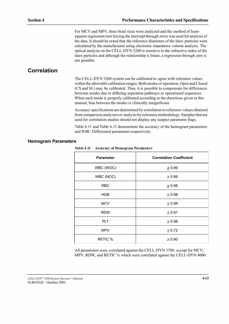
8/21/2019 Equ22-14 CellDyn3200 Op Man
http://slidepdf.com/reader/full/equ22-14-celldyn3200-op-man 151/690
CELL-DYN ® 3200 System Operator’s Manual 4-13
9140181H—October 2001
Section 4 Performance Characteristics and Specifications
For MCV and MPV, three bead sizes were analyzed and the method of least-
squares regression (not forcing the intercept through zero) was used for analysis of
the data. It should be noted that the reference diameters of the latex particles were
calculated by the manufacturer using electronic impedance volume analysis. The
optical analysis on the CELL-DYN 3200 is sensitive to the refractive index of the
latex particles and although the relationship is linear, a regression through zero isnot possible.
Correlation
The CELL-DYN 3200 system can be calibrated to agree with reference values
within the allowable calibration ranges. Both modes of operation, Open and Closed
(CS and SL) may be calibrated. Thus, it is possible to compensate for differences
between modes due to differing aspiration pathways or operational sequences.
When each mode is properly calibrated according to the directions given in this
manual, bias between the modes is clinically insignificant.
Accuracy specifications are determined by correlation to reference values obtained
from comparison analyzers or analysis by reference methodology. Samples that areused for correlation studies should not display any suspect parameter flags.
Table 4.11 and Table 4.12 demonstrate the accuracy of the hemogram parameters
and WBC Differential parameters respectively.
Hemogram Parameters
All parameters were correlated against the CELL-DYN 3700, except for MCV,
MPV, RDW, and RETIC % which were correlated against the CELL-DYN 4000.
Table 4.11 Accuracy of Hemogram Parameters
Parameter Correlation Coefficient
WBC (WOC) > 0.99
WBC (NOC) > 0.99
RBC > 0.98
HGB > 0.98
MCV > 0.98
RDW > 0.91
PLT > 0.98
MPV > 0.72
RETIC % > 0.90

8/21/2019 Equ22-14 CellDyn3200 Op Man
http://slidepdf.com/reader/full/equ22-14-celldyn3200-op-man 152/690
4-14 CELL-DYN ® 3200 System Operator’s Manual
9140181H—October 2001
Performance Characteristics and Specifications
Performance Specifications Section 4
WBC Differential Parameters
Comprehensive Flagging
Table 4.12 Accuracy of WBC Differential Parameters
Parameter Correlation Coefficient
Neutrophil # and % > 0.95
Lymphocyte # and % > 0.94
Monocyte # and % > 0.86
Eosinophil # and % > 0.84
Basophil # and % > 0.73
Table 4.13 Flagging Analysis Using both the Distributional
and Morphological Flags
Agreement True Negative and True Positive > 80%
False Positives < 20%
False Negatives < 1%
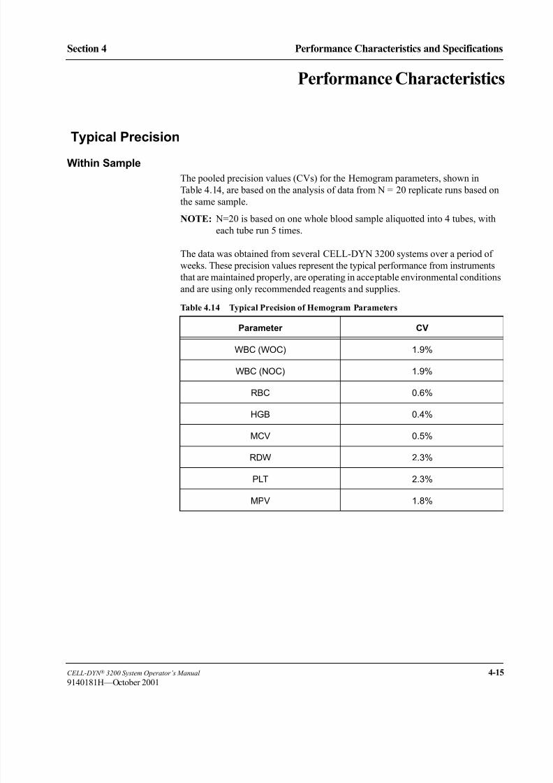
8/21/2019 Equ22-14 CellDyn3200 Op Man
http://slidepdf.com/reader/full/equ22-14-celldyn3200-op-man 153/690
CELL-DYN ® 3200 System Operator’s Manual 4-15
9140181H—October 2001
Section 4 Performance Characteristics and Specifications
Performance Characteristics
Typical Precision
Within Sample
The pooled precision values (CVs) for the Hemogram parameters, shown in
Table 4.14, are based on the analysis of data from N = 20 replicate runs based on
the same sample.
NOTE: N=20 is based on one whole blood sample aliquotted into 4 tubes, with
each tube run 5 times.
The data was obtained from several CELL-DYN 3200 systems over a period of
weeks. These precision values represent the typical performance from instruments
that are maintained properly, are operating in acceptable environmental conditionsand are using only recommended reagents and supplies.
Table 4.14 Typical Precision of Hemogram Parameters
Parameter CV
WBC (WOC) 1.9%
WBC (NOC) 1.9%
RBC 0.6%
HGB 0.4%
MCV 0.5%
RDW 2.3%
PLT 2.3%
MPV 1.8%
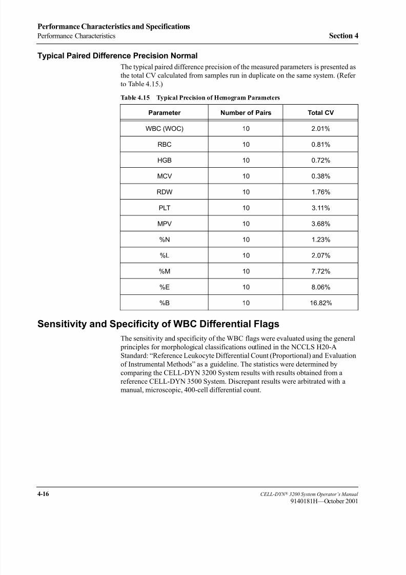
8/21/2019 Equ22-14 CellDyn3200 Op Man
http://slidepdf.com/reader/full/equ22-14-celldyn3200-op-man 154/690
4-16 CELL-DYN ® 3200 System Operator’s Manual
9140181H—October 2001
Performance Characteristics and Specifications
Performance Characteristics Section 4
Typical Paired Difference Precision Normal
The typical paired difference precision of the measured parameters is presented as
the total CV calculated from samples run in duplicate on the same system. (Refer
to Table 4.15.)
Sensitivity and Specificity of WBC Differential Flags
The sensitivity and specificity of the WBC flags were evaluated using the general
principles for morphological classifications outlined in the NCCLS H20-A
Standard: “Reference Leukocyte Differential Count (Proportional) and Evaluation
of Instrumental Methods” as a guideline. The statistics were determined by
comparing the CELL-DYN 3200 System results with results obtained from a
reference CELL-DYN 3500 System. Discrepant results were arbitrated with a
manual, microscopic, 400-cell differential count.
Table 4.15 Typical Precision of Hemogram Parameters
Parameter Number of Pairs Total CV
WBC (WOC) 10 2.01%
RBC 10 0.81%
HGB 10 0.72%
MCV 10 0.38%
RDW 10 1.76%
PLT 10 3.11%
MPV 10 3.68%
%N 10 1.23%
%L 10 2.07%
%M 10 7.72%
%E 10 8.06%
%B 10 16.82%

8/21/2019 Equ22-14 CellDyn3200 Op Man
http://slidepdf.com/reader/full/equ22-14-celldyn3200-op-man 155/690
CELL-DYN ® 3200 System Operator’s Manual 4-17
9140181H—October 2001
Section 4 Performance Characteristics and Specifications
Abnormalities
The following tables present a list of abnormalities targeted during this evaluation
and the resultant data.
Table 4.16 lists the various types of specimens that the sites attempted to collect
during this evaluation:
Table 4.16 Abnormalities
1. RBC count <4.00 M/mL 19. Lipemic
2. RBC count >6.20 M/mL 20. Basophils >3%
3. WBC count <4.0 K/mL 21. Icteric
4. WBC count >11.0 K/mL 22. Hemoglobinopathies S and C
5. WBC count >100.0 K/mL 23. Containing macrocytic PLTs
6. PLT count <150 K/mL 24. Uremic
7. PLT count >450 K/mL 25. Paraproteinemia
8. MCV <60 fL 26. Patients on immunosuppressant therapy
9. MCV >110 fL 27. Containing cryoglobulins
10. Containing RBCs resistant to lysis 28. Containing micro clots
11. Containing agranular neutrophils 29. Containing cell fragments
12. Containing variant lymphocytes 30. Platelet satellitosis condition
13. Containing lymphoblasts 31. Containing cold agglutinins
14. Containing bands >5% 32. Containing dual RBC populations
15. Immature granulocytes (myelos, metas, pros) 33. Containing Heinz and Howell-Jolly Bodies
16. Containing myeloblasts/monoblasts 34. Containing Malarial Parasites
17. Containing > 1 NRBC per 100 WBCs 35. Containing >5.0% Reticulocytes
18. Hypogranular eosinophils 36. Chronic Lymphocytic Leukemia (CLL)
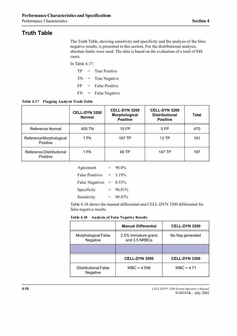
8/21/2019 Equ22-14 CellDyn3200 Op Man
http://slidepdf.com/reader/full/equ22-14-celldyn3200-op-man 156/690
4-18 CELL-DYN ® 3200 System Operator’s Manual
9140181K—July 2002
Performance Characteristics and Specifications
Performance Characteristics Section 4
Truth Table
The Truth Table, showing sensitivity and specificity and the analysis of the false
negative results, is presented in this section. For the distributional analysis,
absolute limits were used. The data is based on the evaluation of a total of 848
cases.
In Table 4.17:
TP = True Positive
TN = True Negative
FP = False Positive
FN = False Negative
Agreement = 98.0%
False Positives = 3.19%False Negatives = 0.53%
Specificity = 96.81%
Sensitivity = 99.47%
Table 4.18 shows the manual differential and CELL-DYN 3200 differential for
false negative results.
Table 4.17 Flagging Analysis Truth Table
CELL-DYN 3200
Normal
CELL-DYN 3200
Morphological
Positive
CELL-DYN 3200
Distributional
Positive
Total
Reference Normal 455 TN 15 FP 0 FP 470
Reference Morphological
Positive
1 FN 167 TP 13 TP 181
Reference Distributional
Positive
1 FN 49 TP 147 TP 197
Table 4.18 Analysis of False Negative Results
Manual Differential CELL-DYN 3200
Morphological FalseNegative
2.5% Immature gransand 3.5 NRBCs
No flag generated
CELL-DYN 3500 CELL-DYN 3200
Distributional False
Negative
WBC = 4.596 WBC = 4.71

8/21/2019 Equ22-14 CellDyn3200 Op Man
http://slidepdf.com/reader/full/equ22-14-celldyn3200-op-man 157/690
CELL-DYN ® 3200 System Operator’s Manual 4-19
9140181H—October 2001
Section 4 Performance Characteristics and Specifications
Sample Loader Specifications
Sample Loader Physical SpecificationsThe Sample Loader attaches to the front of the CELL-DYN 3200SL Analyzer and
is an integral part of the SL model. Table 4.19 contains the physical specifications
for the Sample Loader.
Table 4.19 Sample Loader Physical Specifications
Sample Loader (with skirt)
Height 6" (15.2 cm)
Width 32.5" (82.5 cm)
Depth 6.4" (16.2 cm)
Weight 18 lb (8.1 kg)

8/21/2019 Equ22-14 CellDyn3200 Op Man
http://slidepdf.com/reader/full/equ22-14-celldyn3200-op-man 158/690
4-20 CELL-DYN ® 3200 System Operator’s Manual
9140181H—October 2001
Performance Characteristics and Specifications
Sample Loader Specifications Section 4
Sample Loader Operational Specifications
Operational specifications for the Sample Loader are given in Table 4.20.
For information on tube types and size, refer to Tube Types in Section 13: Sample
Loader ; Subsection: Physical and Performance Specifications.
For information on bar codes types and operation, refer to Appendix A: Bar
Codes.
For general information on Sample Loader operation, refer to Section 13: Sample
Loader ; Subsection: Sample Loader Description.
Table 4.20 Sample Loader Operational Specifications
Feature Specification
Rack Capacity 5 racks on the load side;
5 racks on the unload side
Tube Capacity 50 (10 tubes per rack)
Sample Throughput
(1) Patient
(2) FWBC, RRBC, QC
(1) 58 samples/hour
(2) 34 samples/hour
Run Cycle Time
(1) Patient(2) FWBC, RRBC, QC
(1) 62 seconds(2) 105 seconds
Number of Mixing Stations 2: Mixing Stations #1 and #2
Degree of Mixing Rotation 0 – 135 degrees
Number of Mixing Rotations 15 times at Mixing Station #1
15 times at Mixing Station #2
Maximum Tube Size 16mm (DIA) X 80mm (High)
Bar Code Reader LED type
Bar Code Labels Code 39, I2of5, Codabar, Code 128
8/21/2019 Equ22-14 CellDyn3200 Op Man
http://slidepdf.com/reader/full/equ22-14-celldyn3200-op-man 159/690
CELL-DYN ® 3200 System Operator’s Manual 5-1
9140181H—October 2001
Section 5 Operating Instructions
ec on perat ng nstruct ons
Overview
This section, which discusses the operation of the CELL-DYN 3200, is dividedinto eight major subsections:
Data Module Program Overview
Software Flowcharts
Set Up Instructions
Specimen Collection and Handling
Routine Operation
Sample Analysis
Work List
Using the Data Log
The three major menus in the program that are used for routine operation —SET UP, RUN, and DATA LOG — are discussed in this section. The remaining parts
of the program are discussed in the following sections:
Calibration Section 6: Calibration Procedures
Special Protocols Section 9: Service and Maintenance
Troubleshooting Section 10: Troubleshooting and Diagnostics
Quality Control Section 11: Quality Control

8/21/2019 Equ22-14 CellDyn3200 Op Man
http://slidepdf.com/reader/full/equ22-14-celldyn3200-op-man 160/690
5-2 CELL-DYN ® 3200 System Operator’s Manual
9140181H—October 2001
Operating Instructions
Overview Section 5
NOTES

8/21/2019 Equ22-14 CellDyn3200 Op Man
http://slidepdf.com/reader/full/equ22-14-celldyn3200-op-man 161/690
CELL-DYN ® 3200 System Operator’s Manual 5-3
9140181H—October 2001
Section 5 Operating Instructions
Data Module Program Overview
The Data Module menus are presented as key labels displayed across the bottom ofthe screen. Each menu is accessed by pressing the soft key located directly below
the label. From left to right, these soft keys correspond to keys F1–F8 on the
standard computer keyboard.
When the system is powered ON, the MAIN MENU screen, depicted in Figure 5.1, is
displayed. The key labels displayed across the bottom of this screen are used to
access all of the sub-menus that are available. The main menu keys are listed
below.
MAIN MENU keys:
SET UP
RUN
DATA LOG
RETIC DATA LOG
QUALITY CONTROL
CALIBRATION
DIAGNOSTICS
SPECIAL PROTOCOLS
NOTE: Reticulocyte menu operating instructions are detailed in Section 14:
Reticulocyte Package.
Main Menu Screen
The MAIN MENU screen is divided into four sections. The upper left-hand corner
shows the current version of the Data Module software. The upper right hand
corner shows the current date and time, operator ID and the sequence number. The
information in the upper right corner is displayed on every screen during operation.

8/21/2019 Equ22-14 CellDyn3200 Op Man
http://slidepdf.com/reader/full/equ22-14-celldyn3200-op-man 162/690
5-4 CELL-DYN ® 3200 System Operator’s Manual
9140181H—October 2001
Operating Instructions
Data Module Program Overview Section 5
Figure 5.1 Main Menu Screen
NOTE: The cursor is positioned at the <Operator ID> field when the MAIN MENU
screen is displayed. An operator ID of up to three alphanumeric characters
may be entered. (An operator ID may also be entered from the main
CALIBRATION screen.) This operator ID will be displayed on all screens
and printed on all reports.
The Status Box is displayed in the top center of the screen. This box appears on
every screen to show the following:
Menu in use
Analyzer status
Other applicable information such as file identity, Sample ID number, and any
existing fault conditions
The MAIN MENU key labels are displayed across the bottom of the screen.
Feb 23, 2001
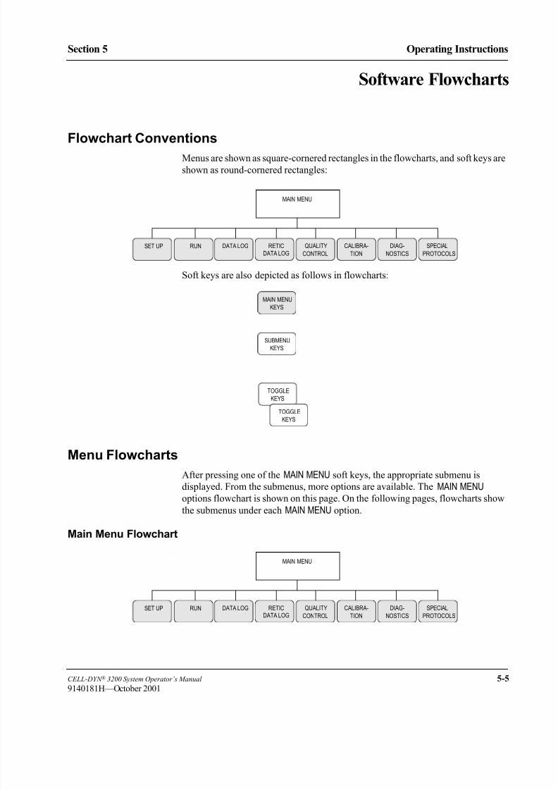
8/21/2019 Equ22-14 CellDyn3200 Op Man
http://slidepdf.com/reader/full/equ22-14-celldyn3200-op-man 163/690
CELL-DYN ® 3200 System Operator’s Manual 5-5
9140181H—October 2001
Section 5 Operating Instructions
Software Flowcharts
Flowchart ConventionsMenus are shown as square-cornered rectangles in the flowcharts, and soft keys are
shown as round-cornered rectangles:
Soft keys are also depicted as follows in flowcharts:
Menu Flowcharts
After pressing one of the MAIN MENU soft keys, the appropriate submenu is
displayed. From the submenus, more options are available. The MAIN MENU
options flowchart is shown on this page. On the following pages, flowcharts show
the submenus under each MAIN MENU option.
Main Menu Flowchart
MAIN MENU
SET UP DIAG-RUN CALIBRA-RETIC QUALITY
CONTROL TION NOSTICS
SPECIAL
PROTOCOLS
DATA LOGDATA LOG
MAIN MENU
KEYS
SUBMENU
KEYS
TOGGLE
KEYS
TOGGLE
KEYS
MAIN MENU
SET UP DIAG-RUN CALIBRA-RETIC QUALITY
CONTROL TION NOSTICS
SPECIAL
PROTOCOLS
DATA LOGDATA LOG

8/21/2019 Equ22-14 CellDyn3200 Op Man
http://slidepdf.com/reader/full/equ22-14-celldyn3200-op-man 164/690

8/21/2019 Equ22-14 CellDyn3200 Op Man
http://slidepdf.com/reader/full/equ22-14-celldyn3200-op-man 165/690
CELL-DYN ® 3200 System Operator’s Manual 5-7
9140181L—July 2003
Section 5 Operating Instructions
Run Menu Flowchart
Data Log Menu Flowchart
CANCELCONFIRMDELETION SELECTION
RUN
MAINSTARTLOADER
PRINTTICKET
PRINTREPORT
WORKLIST
CHANGESAMPLER
SPECIMENTYPE
CUSTOMIZEREPORT
CLEARFAULT
PRIME
COLORPRINT
PATIENT RESISTANTRBC
RETURN
QCSPECIMEN
LATEXBACK-GROUND
FRAGILEWBC
RETURNWORK LISTSET UP
PRINTWORK LIST
INSERT/DELETE
DELETE ALL
see CUSTOMIZE REPORTon SET UP MENU
RETURNINSERT DELETE
RETURNTOGGLEON/OFF
STOPLOADER
RESETRESUME
EDITID FIND SPECIMEN
PREVIOUS SPECIMEN
NEXT SPECIMEN
EDIT SPECIMEN SPECIMEN
TRANSMIT
DATA LOG
DISPLAYSPECIMEN MAINTRANSMIT DATA PRINTDATA LOG
RETURNPRINTREPORT
CUSTOMIZEDATA LOG
REPORTCUSTOMIZE
TICKETPRINT
see CUSTOMIZE REPORTon SET UP MENU
SELECT PARAMETER
STANDARD GROUPS
RETURN
CANCELCONFIRM
PRINTOUTCUSTOMIZE
WBC GROUP
RBC GROUP
PLT GROUP GROUP
DIFF RETURNCUSTOMIZEPRINTOUTPLACEMENT
CUSTOM
REJECTFROM X-B
ACCEPTINTO X-B
RETURNSELECTPARAMETER
STANDARDSELECTION
RETURNPLACEPARAMETER
CANCELSELECTION
RETURNPLACEPARAMETER
CANCELSELECTION
COLORPRINT

8/21/2019 Equ22-14 CellDyn3200 Op Man
http://slidepdf.com/reader/full/equ22-14-celldyn3200-op-man 166/690
5-8 CELL-DYN ® 3200 System Operator’s Manual
9140181K—July 2002
Operating Instructions
Software Flowcharts Section 5
Quality Control Menu Flowchart
RETURNCONFIRMUPDATE
UPDATEFROM FILE
PURGECANCELCONFIRM
PURGE
QC MENUReady
CUSTOMIZEVIEWQC LOG
QCLIMITS DISPLAY
SET UPQC FILE
RETURNPURGEQC LOG
PRINTQC LOG
LEVEY-JENNINGS
MOVESPECIMEN
REJECTSPECIMEN
DELETESPECIMEN
ACCEPTSPECIMEN
RETURNRANGEENTRY
RETURNPRINTTOGGLEON/OFF
RETURNPRINTGROUP3
GROUP4
X-B CUSTOMIZEPRINTOUT
MAINFILE
X-BSET UP
LOAD
MEANS/LIMITS
FROM DISK
GROUP2
GROUP1
RETURNPRINTTURN X-BWBC ON
TURN X-BWBC OFF
RETURNPRINTX-B WBCGRAPHS
X-B WBCDATA
DELETIONCANCELCONFIRM
DELETION
RETURNSTANDARDSELECTION
CANCELSELECTION
SELECTPARAMETER
RETURNWRITEHIGH
WRITENORMAL
WRITELOW
PLACEPARAMETER
RETURNSTANDARDGROUPS
CANCELSELECTION
SELECTPARAMETER
PLACEPARAMETER
CANCELMOVE
MOVE TOFILE
X-B RBCGRAPHS
X-B RBCDATA
TURN X-BRBC ON
TURN X-BRBC OFF
WBC GROUP
RBC GROUP
PLT GROUP GROUP
DIFF
REPLICATEID
RETURNLOADLOADNORMAL
LOADLOW HIGH
PLACEMENTCUSTOM
LOTNUMBER
PREVIOUS10
NEXT10
RETURN SET
LATEX
WRITE QCTO DISK

8/21/2019 Equ22-14 CellDyn3200 Op Man
http://slidepdf.com/reader/full/equ22-14-celldyn3200-op-man 167/690
CELL-DYN ® 3200 System Operator’s Manual 5-9
9140181H—October 2001
Section 5 Operating Instructions
Calibration Menu Flowchart
CALIBRATIONReady
ENTERFACTOR
MAIN
CALIBRATIONLOG
PRINT AUTOCALIBRATE
CLOSEDSAMPLER
OPENSAMPLER
RESTOREFACTORS
RESET ALLTO 1.000
RETURN
RETURN
PRINTLOG
CLOSEDSAMPLER
OPENSAMPLER
*CALIBRATOR*WHOLE BLOOD
RETURN
QUIT RETURN
START AUTO-CAL
CANCELQUIT
CONFIRMQUIT
QUITDELETE A RUN
RETURN
PRINT ACCEPT
CANCELQUIT
CONFIRMQUIT
*NOTE: Instrument will reflect last mode of calibration, either whole blood or calibrator.

8/21/2019 Equ22-14 CellDyn3200 Op Man
http://slidepdf.com/reader/full/equ22-14-celldyn3200-op-man 168/690
5-10 CELL-DYN ® 3200 System Operator’s Manual
9140181K—July 2002
Operating Instructions
Software Flowcharts Section 5
Diagnostics Menu Flowcharts
DIAGNOSTICS MENUReady
FAULTREPORT MORE EXECUTIONTIMES RAW DATASUMMARYCNT RATESUMMARY CLEARFAULTS MAIN
PRINTNOCCNT RATE
WOCCNT RATE
RBC/PLTCNT RATE
RETURN
MAINMOTOROPERATION
MORE
SOLENOIDOPERATION
INITIAL-IZATION
PUMPOPERATION
DRAIN ACCUMULATOR
DIAG-STEP
SOLENOID
CYCLE
BANK NOSTICS
PRESSUREVACUUMTEST TEST
VACUUMON
PRESSUREON
DIAGNOSTICS
PRINTDIGITALREADINGS MORE VOLTAGEREADINGS GAIN ADJUSTMNT MAIN
NOCCNT GRAPH
WOCCNT GRAPH
RBC/PLTCNT GRAPH
MORE
WBCDATA
NOCDATA
RBCDATA
PLTDATA
MAIN
VACUUMOFF
PRESSUREOFF
PRINTDIGITALREADINGS
MORE
VOLTAGEREADINGS
GAIN ADJUSTMNT
MAINFINISHSELECT
SELECT
VERIFYGAINS
CURRENTSETTINGS
AUTO GAIN ADJUSTMNT
MOREFPUTEST
*LOADERTEST
TOWERTEST
MAIN
NOCHISTOGRAM
RBCHISTOGRAM
PLTHISTOGRAM
PRINTWBC 1DATA
EXTENDEDWBC COUNT
WBC 2DATA
SMOOTHINGON/OFF
CALCCV
SCATTERGRAPHS
TUBESENSOR
STARTRACE ADV
WBC 1HISTOGRAM
WBC 2HISTOGRAM
PRINTSHEAR VALDISPENSE
MOTOR PWRCHECKING
SHEAR VALTIME
HOMEMOTORS
EXERCISEMOTORS
SHEAR VAL ASPIRATE
Y-VALVETO CLOSE
Y-VALVETO OPEN
SOFTWAREVERSIONS
SERIALTEST
BAR CODE ALIGNMENT
CYCLEBLADDERS
ROTATEMIXUP
MIXERDOWN
RETURN
TRANSMITMESSAGE
STOPTRANSMISS
SENSORTEST
SPINMOTOR
RETRACTSOLENOID
NEEDLEDOWN
**
* SL only** This information appears on the next page.
RBC LINDATA
RBC LINHISTOGRAM
**
DIAGNOSTICS
DIAGNOSTICS
DIAGNOSTICS
DIAGNOSTICS
DIAGNOSTICS
WOCCNT DATA
NOCCNT DATA
RBC/PLTCNT DATA
EXTEND ARMS
TUBEBARCODE
READRATE
RACKBARCODE
RETURN

8/21/2019 Equ22-14 CellDyn3200 Op Man
http://slidepdf.com/reader/full/equ22-14-celldyn3200-op-man 169/690
CELL-DYN ® 3200 System Operator’s Manual 5-11
9140181H—October 2001
Section 5 Operating Instructions
Diagnostics Menu Flowchart (continued)
DIAGNOSTICS
MORE
WBCDATA
NOCDATA
RBCDATA
PLTDATA
SMOOTHINGRBC 90DATA ON/OFF
RBC 0DATA
RBC 10DATA
RBC 0HISTOGRAM
RBC 10HISTOGRAM
MORE
MORE
RBC 90HISTOGRAM
SMOOTHINGON/OFF
PLT 0DATA
PLT 10DATA
PLT 0HISTOGRAM
PLT 10HISTOGRAM
NOC 00NOC 10
NOC 0DATA
NOC 10DATA
NOC 90NOC10
NOC 0HISTOGRAM
NOC 10HISTOGRAM
NOC 90NOC00
RBC LIN 90DATA
RBC LIN 0DATA
RBC LIN 10DATA
RBC VOLUMEDATA
RBC LIN 0HISTOGRAM
RBC LIN 10HISTOGRAM
SMOOTHINGON/OFF
RBC LINDATA
RBC LIN 90HISTOGRAM
PRINTCALCCV
DIAGNOSTICS
DIAGNOSTICS
DIAGNOSTICS
DIAGNOSTICS

8/21/2019 Equ22-14 CellDyn3200 Op Man
http://slidepdf.com/reader/full/equ22-14-celldyn3200-op-man 170/690
5-12 CELL-DYN ® 3200 System Operator’s Manual
9140181H—October 2001
Operating Instructions
Software Flowcharts Section 5
Special Protocols Flowchart
SPECIAL PROTOCOLS
MOREDISABLE/ENAB ANALYZER
EMPTY/FILLFLOW CELL
CLEARFAULT
CLEAN/RESSHEAR VALVE
REAGENTRESERVOIR
MAIN
RETURNEMPTYWBC LYSE
EMPTYHGB LYSE
EMPTYDIL/SHEATH
MAINEXTEND AUTOCLEAN
MORE
AUTOCLEAN
CLEANNEEDLE
DAILYSHUTDOWN
PREPARESHIPPING
FILL WBC LYSE
FILLHGB LYSE
FILLDIL/SHEATH
EMPTYFLOW CELL
RETURN
FILLFLOW CELL
CLEANSHEAR
RETURN
VALVE
RESTORESHEARVALVE
DISABLE ANALYZER
RETURN
ENABLE ANALYZER

8/21/2019 Equ22-14 CellDyn3200 Op Man
http://slidepdf.com/reader/full/equ22-14-celldyn3200-op-man 171/690
CELL-DYN ® 3200 System Operator’s Manual 5-13
9140181H—October 2001
Section 5 Operating Instructions
Set Up Instructions
This section discusses the options available when the [SET UP] key is pressed. (SeeFigure 5.2.) These options are used to configure the system according to the
laboratory’s requirements. The function of each key is discussed and set up
procedures are given where applicable.
Figure 5.2 Set Up Menu Screen
Set Up Menu
When the [SET UP] key is pressed, the following soft key labels are displayed:
DATE/TIME
PATIENT LIMITS
REAGENT LOG
QC SET UP MENUOPERATION SET UP
UNITS SELECTION
CUSTOMIZE REPORT
MAIN

8/21/2019 Equ22-14 CellDyn3200 Op Man
http://slidepdf.com/reader/full/equ22-14-celldyn3200-op-man 172/690
5-14 CELL-DYN ® 3200 System Operator’s Manual
9140181H—October 2001
Operating Instructions
Set Up Instructions Section 5
Figure 5.3 Date/Time Set Up Screen
Date/Time
The [DATE/TIME] key is used to enter the date and time. This screen allows the
operator to select the format for displaying the date and to change the date and time
as required. Four different date formats are available. The numbers on the
DATE/TIME SET UP screen shown in Figure 5.3 correspond to the following
numbered options:
1. Display Format selection box:
1. Month/Day/Year
2. Day/Month/Year
3. Year/Month/Day
4. Year/Day/Month
2. DATE entry field
3. TIME entry field
The desired format is selected by typing the corresponding number in the entry
field displayed to the left of the list (1). When the Enter key on the keyboard is pressed, the selected format is displayed in the DATE entry field (2, below the
format selection box) and the cursor moves to the entry position. After the date has
been entered, the cursor moves to the TIME entry field (3).

8/21/2019 Equ22-14 CellDyn3200 Op Man
http://slidepdf.com/reader/full/equ22-14-celldyn3200-op-man 173/690
CELL-DYN ® 3200 System Operator’s Manual 5-15
9140181H—October 2001
Section 5 Operating Instructions
To Set Date/Time
1. From the SET UP MENU screen, press [DATE/TIME] to display the DATE/TIMESET UP screen.
2. Type the number of the desired format at the cursor.
3. Press the Enter key on the keyboard to save the entry and advance to the
DATE entry field.
4. Type the date in the selected format using one or two digits. Separate the day,
month and year (year must be 4 digits) with a slash (/) or a period (.). The
entry order of the date should conform to the date format just selected.
5. Press the Enter key on the keyboard to save the entry and advance to the
TIME entry field.
6. Type the time in the 24-hour (military) time format using one or two digits.
(For example, 00 for 12 midnight, 06 for 6 am, and 13 for 1 pm.) Separate the
hours and minutes with a colon (:) or a period (.).
7. Press the Enter key on the keyboard to save the entry.
8. Press [RETURN] to return to the SET UP MENU screen.
Figure 5.4 Patient Limits Screen

8/21/2019 Equ22-14 CellDyn3200 Op Man
http://slidepdf.com/reader/full/equ22-14-celldyn3200-op-man 174/690
5-16 CELL-DYN ® 3200 System Operator’s Manual
9140181M—June 2004
Operating Instructions
Set Up Instructions Section 5
Patient Limits
The [PATIENT LIMITS] key is used to enter upper and lower flagging limits for
groups of patient samples. (For example, limits may be entered for adult males,
adult females, neonates, etc.) The following soft key labels are displayed (See
Figure 5.4.) when the [PATIENT LIMITS] key is pressed:
LIMIT SET 1
LIMIT SET 2
LIMIT SET 3
LIMIT SET 4
LIMIT SET 5
LIMIT SET 6
RETURN
NOTE: The key label for the limit set displayed on the screen is not shown.
Six different sets of limits may be entered. Whenever a parameter result exceeds anentered limit, the result is displayed in color on the screen to alert the operator.
Results displayed in yellow are below the limit and results displayed in purple are
above the limit. The flagged result is underlined on the graphics report and the
blank ticket report. The flagged result is marked with an asterisk (*) on the
pre-printed ticket report.
LIMIT SET 1 contains upper and lower limits pre-set at the factory. Once these
limits are changed, the operator can return to the factory-set limits by either
manually inputting the factory-set limits or by re-installing the Set Up Disk.
LIMIT SETS 2 through 6 contain zeros for the lower limits and 9s for the upper
limits when the instrument is first installed.
In addition to entering limit set data, the operator can also pre-assign limit sets to
patients based on patient sex and age.
Dispersional Data Alerts
It is suggested that one Patient Limit Set be used to enter instrument-specific
laboratory action limits. If the Interpretive Report option is enabled, the
Interpretive messages, such as leukocytosis, anemia, thrombocytopenia, etc., will
be displayed when a result falls outside the appropriate limit. A result that falls
outside a laboratory action limit can also indicate the need for the operator to
follow a laboratory protocol, such as repeating the sample, notifying the physician
or performing a smear review. In cases where a cellular abnormality is present that
alters cellular morphology to the point that the cells do not fit the criteria used bythe instrument to generate a flag, dispersional data alerts may be the only flag(s)
that will alert the operator to a potentially erroneous result.
Automatic Patient Limit Set Assignment
Sex and Age fields for each Patient Limit Set are shown in the upper left corner of
the LIMIT SET screen.
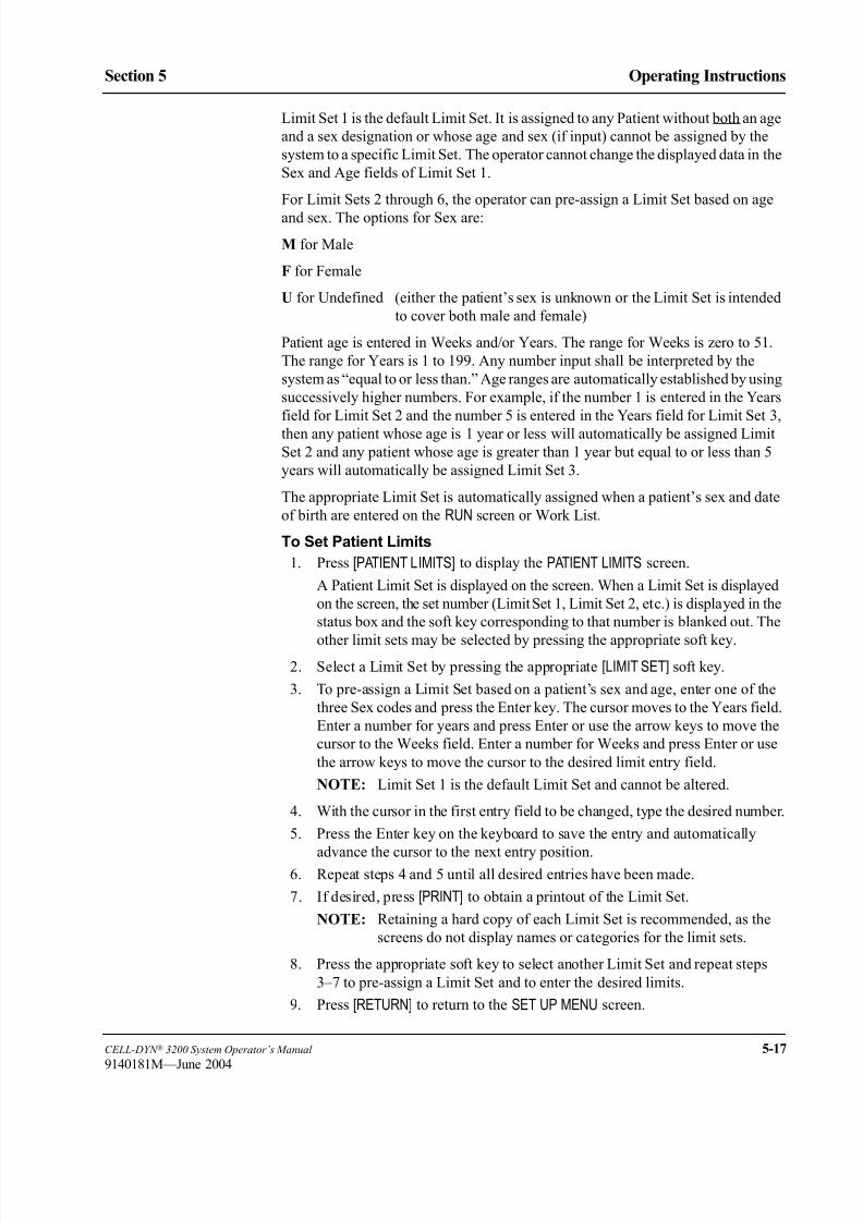
8/21/2019 Equ22-14 CellDyn3200 Op Man
http://slidepdf.com/reader/full/equ22-14-celldyn3200-op-man 175/690
CELL-DYN ® 3200 System Operator’s Manual 5-17
9140181M—June 2004
Section 5 Operating Instructions
Limit Set 1 is the default Limit Set. It is assigned to any Patient without both an age
and a sex designation or whose age and sex (if input) cannot be assigned by the
system to a specific Limit Set. The operator cannot change the displayed data in the
Sex and Age fields of Limit Set 1.
For Limit Sets 2 through 6, the operator can pre-assign a Limit Set based on age
and sex. The options for Sex are:
M for Male
F for Female
U for Undefined (either the patient’s sex is unknown or the Limit Set is intended
to cover both male and female)
Patient age is entered in Weeks and/or Years. The range for Weeks is zero to 51.
The range for Years is 1 to 199. Any number input shall be interpreted by the
system as “equal to or less than.” Age ranges are automatically established by using
successively higher numbers. For example, if the number 1 is entered in the Years
field for Limit Set 2 and the number 5 is entered in the Years field for Limit Set 3,
then any patient whose age is 1 year or less will automatically be assigned Limit
Set 2 and any patient whose age is greater than 1 year but equal to or less than 5
years will automatically be assigned Limit Set 3.
The appropriate Limit Set is automatically assigned when a patient’s sex and date
of birth are entered on the RUN screen or Work List.
To Set Patient Limits
1. Press [PATIENT LIMITS] to display the PATIENT LIMITS screen.
A Patient Limit Set is displayed on the screen. When a Limit Set is displayed
on the screen, the set number (Limit Set 1, Limit Set 2, etc.) is displayed in the
status box and the soft key corresponding to that number is blanked out. The
other limit sets may be selected by pressing the appropriate soft key.
2. Select a Limit Set by pressing the appropriate [LIMIT SET] soft key.
3. To pre-assign a Limit Set based on a patient’s sex and age, enter one of the
three Sex codes and press the Enter key. The cursor moves to the Years field.
Enter a number for years and press Enter or use the arrow keys to move the
cursor to the Weeks field. Enter a number for Weeks and press Enter or use
the arrow keys to move the cursor to the desired limit entry field.
NOTE: Limit Set 1 is the default Limit Set and cannot be altered.
4. With the cursor in the first entry field to be changed, type the desired number.
5. Press the Enter key on the keyboard to save the entry and automatically
advance the cursor to the next entry position.6. Repeat steps 4 and 5 until all desired entries have been made.
7. If desired, press [PRINT] to obtain a printout of the Limit Set.
NOTE: Retaining a hard copy of each Limit Set is recommended, as the
screens do not display names or categories for the limit sets.
8. Press the appropriate soft key to select another Limit Set and repeat steps
3–7 to pre-assign a Limit Set and to enter the desired limits.
9. Press [RETURN] to return to the SET UP MENU screen.

8/21/2019 Equ22-14 CellDyn3200 Op Man
http://slidepdf.com/reader/full/equ22-14-celldyn3200-op-man 176/690
5-18 CELL-DYN ® 3200 System Operator’s Manual
9140181H—October 2001
Operating Instructions
Set Up Instructions Section 5
Figure 5.5 Diluent/Sheath Log Screen
Reagent Log
The [REAGENT LOG] key is used to enter current reagent information into the three
reagent logs. The following soft key labels are displayed when the [REAGENT LOG] key is pressed:
DELETE ENTRYDIL/SHEATH LOGHGB LYSE LOGWBC LYSE LOG
PRINT LOGRETURN
NOTE: The key label for the reagent log displayed in the Status Box is not
displayed with the other keys.
When the [REAGENT LOG] key is pressed, one of the logs is displayed as shown in
Figure 5.5. (The name of the displayed log is indicated in the Status Box.) The other
two logs may be displayed by pressing the appropriate soft key. Each log holds 10
entries. The following information may be entered for each reagent:
Package Size Lot Number
Expiration Date Open Date

8/21/2019 Equ22-14 CellDyn3200 Op Man
http://slidepdf.com/reader/full/equ22-14-celldyn3200-op-man 177/690
CELL-DYN ® 3200 System Operator’s Manual 5-19
9140181H—October 2001
Section 5 Operating Instructions
To Complete Reagent Log Entry
1. Press [REAGENT LOG] to display a REAGENT LOG screen.
2. If the desired reagent log is not already displayed, use the soft key to select
the appropriate log.
3. Use the arrow keys on the keyboard to move the cursor to the desired entry
field.
4. Type the appropriate information.
NOTE: Entries for each field of information are optional. Dates should be
entered with a slash (/) or a period (.) separating the month, day and
year.
5. Press the Enter key on the keyboard to save the entry and advance the cursor.
6. Repeat steps 3–5 until all desired entries have been made.
7. If desired, press [PRINT LOG] to obtain a printout of the log.
8. Press the appropriate soft key to select another reagent log and repeat steps
2–7 to enter and print data.

8/21/2019 Equ22-14 CellDyn3200 Op Man
http://slidepdf.com/reader/full/equ22-14-celldyn3200-op-man 178/690
5-20 CELL-DYN ® 3200 System Operator’s Manual
9140181H—October 2001
Operating Instructions
Set Up Instructions Section 5
To Delete Entries
When the log is full (the log holds 10 entries), the oldest entry must be deleted to
create space for a new entry. Abbott suggests that, for documentation purposes, the
log be printed when it is full.
1. Press [REAGENT LOG] to display a REAGENT LOG screen. If necessary, press
a soft key to display the appropriate log.
2. Move the cursor to the oldest entry in the log.
3. Press [DELETE ENTRY]. The [COMPLETE DELETION] and [RESTORE ENTRY] keys are displayed.
4. Press [COMPLETE DELETION] to delete the selected entry.
5. If desired, a new entry may then be made as described above.
NOTE: New entries may also be made by typing over old entries without
deleting them.
6. Press [RETURN] to return to the main SET UP MENU screen.
Figure 5.6 QC Set Up Menu Screen

8/21/2019 Equ22-14 CellDyn3200 Op Man
http://slidepdf.com/reader/full/equ22-14-celldyn3200-op-man 179/690
CELL-DYN ® 3200 System Operator’s Manual 5-21
9140181H—October 2001
Section 5 Operating Instructions
QC Set Up Menu
The [QC SET UP MENU] key is used to display a list of the QC files (see Figure 5.6)
and the following soft key labels:
X-B SET UP
LAB ID SET UPQC LIMITS
SET UP QC FILE
CUSTOMIZE DISPLAY
CUSTOMIZE PRINTOUT
MAIN
This section discusses the procedures that are used to set up the QC files. Typically,
a QC file(s) is set up, then QC Limits are established. Therefore, the keys in the QCSET UP menu will be discussed in this order.
Figure 5.7 X-B Set Up Screen

8/21/2019 Equ22-14 CellDyn3200 Op Man
http://slidepdf.com/reader/full/equ22-14-celldyn3200-op-man 180/690
5-22 CELL-DYN ® 3200 System Operator’s Manual
9140181H—October 2001
Operating Instructions
Set Up Instructions Section 5
X-B Setup Menu
The [X-B SET UP] key is used to select the X-B SET UP screen. (See Figure 5.7.) This
screen is used to enter upper and lower acceptance limits, target values, and action
limits for the X-B Moving Average QC Program for both the WBC and RBC
parameters. The following soft key labels are displayed when the [X-B SET UP] key
is pressed:
TURN X-B RBC ON/ (The key alternates between the selections.)
TURN X-B RBC OFF
TURN X-B WBC ON/ (The key alternates between the selections.)
TURN X-B WBC OFF
RETURN
The following options are available on the X-B SET UP screen shown in Figure 5.7:
1. LOWER/UPPER LIMITS
The Lower and Upper Limits determine which patient results will be used
in the X-B Moving Average calculation. Results that fall outside these limitsare automatically excluded from the X-B calculations. These limits should be
set widely to exclude grossly abnormal samples (such as background counts)
that would bias the calculation but should include at least 95% of the patient
results.
2. TARGET VALUE
The Target Value for X-B Analysis is similar to the assay value for a
commercial control. It is derived from the patient population that is analyzed
on the instrument.
3. ACTION LIMIT
The Action Limit is the acceptable limit of variation around the target value.
NOTE: The X-B Program is discussed in detail in Section 11: Quality Control .
To Set Up X-B
1. Press [X-B SET UP] to display the X-B SET UP screen.
2. Use the Arrow keys on the keyboard to move the cursor to the desired entry
field.
3. Type the numbers and press the Enter key on the keyboard to save the entry
and advance the cursor to the next entry field.
4. Repeat steps 2 and 3 until all entries have been made.
5. If desired, press [PRINT] to obtain a printout of the entered values.6. If the soft key [TURN X-B RBC ON] or [TURN X-B WBC ON] is displayed, press
the appropriate key to enable the X-B program.
NOTE: For example, when the X-B RBC program is enabled the screen
displays the message THE X-B RBC PROGRAM IS ON and the
[TURN X-B RBC OFF] key is displayed.
7. Press [RETURN] to return to the QC SET UP MENU screen.

8/21/2019 Equ22-14 CellDyn3200 Op Man
http://slidepdf.com/reader/full/equ22-14-celldyn3200-op-man 181/690
CELL-DYN ® 3200 System Operator’s Manual 5-23
9140181H—October 2001
Section 5 Operating Instructions
Lab ID Set Up
The [LAB ID SET UP] key on the QC Set Up Menu is used to enter Laboratory
Identification information for the QC files. This information is necessary for
participants in the CELL-DYN Interlaboratory QC Program who wish to submit
their results on a floppy disk. Laboratory Identification must be entered before QC
data can be transferred to the floppy disk.
Procedure: LAB ID SET UP
1. From the MAIN MENU screen, press [SET UP], followed by
[QC SET UP].
2. From the QC Set Up screen, press [LAB ID SET UP] to display the
LAB ID SET UP screen.
3. Type the appropriate information and press the Enter key on the keyboard
after each entry to save it and advance the cursor to the next entry field.
4. If desired, press the Print Screen key on the keyboard to obtain a printout of
the entered information.
5. Press [RETURN] to return to the QC SET UP screen.
QC Limits Menu
The [QC LIMITS] key is used to display the QC MEANS/LIMITS ENTRY screen and the
following soft key labels:
RANGE ENTRY and
MEANS/LIMITS (The key alternates between the selections.)
UPDATE FROM FILE
LOAD FROM DISK
RETURN
QC Limits Entry
QC Limits are entered by pressing the [QC LIMITS] key. This key is available on the
QC SET UP MENU screen and the QC MENU screen. Two types of QC limits are
available:
Means and Limits — used to enter the mean value and a ± range value that defines
the upper and lower flagging limits (see Figure 5.8)
Range Entry — used to enter the upper and lower flagging limits as absolute
numbers (see Figure 5.9)
If Range Entry is selected by pressing the [RANGE ENTRY] key, the current upper
and lower limits for the selected file are displayed as described above. If Means/
Limits entry is selected by pressing the [MEANS/LIMITS] key, the current means and
limits for the selected file are displayed as described above.
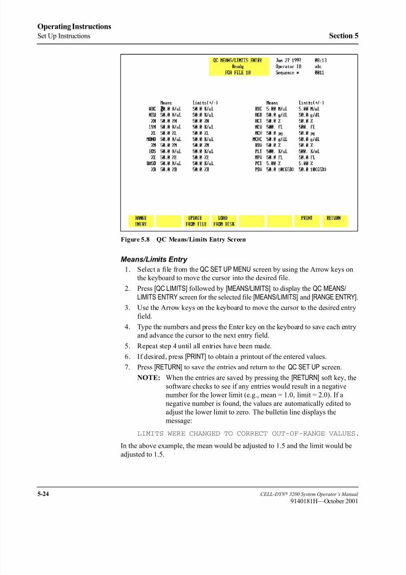
8/21/2019 Equ22-14 CellDyn3200 Op Man
http://slidepdf.com/reader/full/equ22-14-celldyn3200-op-man 182/690
5-24 CELL-DYN ® 3200 System Operator’s Manual
9140181H—October 2001
Operating Instructions
Set Up Instructions Section 5
Figure 5.8 QC Means/Limits Entry Screen
Means/Limits Entry
1. Select a file from the QC SET UP MENU screen by using the Arrow keys on
the keyboard to move the cursor into the desired file.
2. Press [QC LIMITS] followed by [MEANS/LIMITS] to display the QC MEANS/LIMITS ENTRY screen for the selected file [MEANS/LIMITS] and [RANGE ENTRY].
3. Use the Arrow keys on the keyboard to move the cursor to the desired entry
field.
4. Type the numbers and press the Enter key on the keyboard to save each entry
and advance the cursor to the next entry field.
5. Repeat step 4 until all entries have been made.
6. If desired, press [PRINT] to obtain a printout of the entered values.
7. Press [RETURN] to save the entries and return to the QC SET UP screen.
NOTE: When the entries are saved by pressing the [RETURN] soft key, the
software checks to see if any entries would result in a negative
number for the lower limit (e.g., mean = 1.0, limit = 2.0). If a
negative number is found, the values are automatically edited toadjust the lower limit to zero. The bulletin line displays the
message:
LIMITS WERE CHANGED TO CORRECT OUT-OF-RANGE VALUES.
In the above example, the mean would be adjusted to 1.5 and the limit would be
adjusted to 1.5.

8/21/2019 Equ22-14 CellDyn3200 Op Man
http://slidepdf.com/reader/full/equ22-14-celldyn3200-op-man 183/690
CELL-DYN ® 3200 System Operator’s Manual 5-25
9140181H—October 2001
Section 5 Operating Instructions
Figure 5.9 QC Range Entry Screen
Range Entry
1. Select a file from the QC SET UP screen by using the Arrow keys on the
keyboard to move the cursor into the desired file.
2. Press [QC LIMITS] to display the QC RANGE ENTRY screen for the selected file.
3. Use the Arrow keys on the keyboard to move the cursor to the desired entryfield.
4. Type the numbers and press the Enter key on the keyboard to save each entry
and advance the cursor to the next entry field.
5. Repeat step 4 until all entries have been made.
6. If desired, press [PRINT] to obtain a printout of the entered values.
7. Press [RETURN] to save the entries and return to the QC SET UP screen.
NOTE: When the entries are saved by pressing the [RETURN] soft key, the
software checks to see if any entries would result in the upper limit
being less than the lower limit. If this situation occurs, the limits are
automatically reversed. The bulletin line displays the message:
LIMITS WERE EXCHANGED TO MAKE UPPER > LOWER

8/21/2019 Equ22-14 CellDyn3200 Op Man
http://slidepdf.com/reader/full/equ22-14-celldyn3200-op-man 184/690
5-26 CELL-DYN ® 3200 System Operator’s Manual
9140181H—October 2001
Operating Instructions
Set Up Instructions Section 5
Figure 5.10 Update From File Key
Update From File
The [UPDATE FROM FILE] key is displayed on the QC MEANS/LIMITS ENTRY and QCRANGE ENTRY screens when there are two or more results in the file. (See Figure
5.10.) When the [UPDATE FROM FILE] key is pressed, the bulletin line displays the
messageUSE CONFIRM UPDATE TO SET MEANS AND LIMITS FROM QC
FILE and the following soft key labels are displayed:
CONFIRM UPDATE
CANCEL UPDATE
These keys are used to [CONFIRM] or [CANCEL] the Update From File command.
When the [CONFIRM UPDATE] key is pressed, the mean value for each parameter is
computed from the values in the file. The parameter limits are set as follows:
WBC, PLT, RDW and MPV: ± 10% of the computed mean
NEU, LYM and MONO: ± 40% of the computed mean
Remaining Parameters: ± 5% of the computed mean
Load From Disk
The [LOAD FROM DISK] key is used to enter the lot number, expiration date, and
assay values into a QC file directly from a floppy disk. When this option is used,
the lot number, expiration date, mean value and limits (either for QC Range entry
or QC Means/Limits entry) are automatically entered in the selected file. The
values may be edited after they are displayed on the screen.
NOTE: The information is entered for each level, one level at a time.
8/21/2019 Equ22-14 CellDyn3200 Op Man
http://slidepdf.com/reader/full/equ22-14-celldyn3200-op-man 185/690
CELL-DYN ® 3200 System Operator’s Manual 5-27
9140181H—October 2001
Section 5 Operating Instructions
Procedure: Load From Disk
1. Press [QUALITY CONTROL] to display a list of QC files.
2. Use the arrow keys on the keyboard to move the cursor to the desired file.
Type the file name (e.g., Low L0036) and press the Enter key on the keyboard
to save the name and advance the cursor to the next file.
NOTE: The file must be empty in order to load the information from the
disk.
3. When the desired files have been named, use the Arrow keys on the keyboard
to move the cursor back to the first file desired for data entry.
4. Press [QC LIMITS] followed by [MEANS/LIMITS] or
[RANGE ENTRY] to display the QC MEANS/LIMITS ENTRY or RANGE ENTRY
screen for the selected file.
5. Press [LOAD FROM DISK] to display the LOAD FROM DISK screen.
6. Insert the disk containing the assay information for the relevant lot number
into the Data Station disk drive.
NOTE: Be certain to carefully check lot numbers. Be sure the lot numberon the disk matches the lot number that is being put into use. If the
lot number is included in the filename, be sure the disk contains
assay information for that lot number.
7. Check the status box to be sure the correct file is selected and press the
appropriate soft key:
[LOAD LOW] to load the low control assay data.
[LOAD NORMAL] to load the normal control assay data.
[LOAD HIGH] to load the high control assay data.
8. The limits are displayed for the selected file. If desired, the limits may be
edited.9. Press [RETURN] to return to the QC MENU screen.
10. Select the next file and repeat steps 7 and 8 to load the assay data for the
appropriate level of control.
11. Repeat steps 8-11 until the assay data for each level has been loaded.
12. When all the assay data has been loaded, remove the disk from the disk drive.
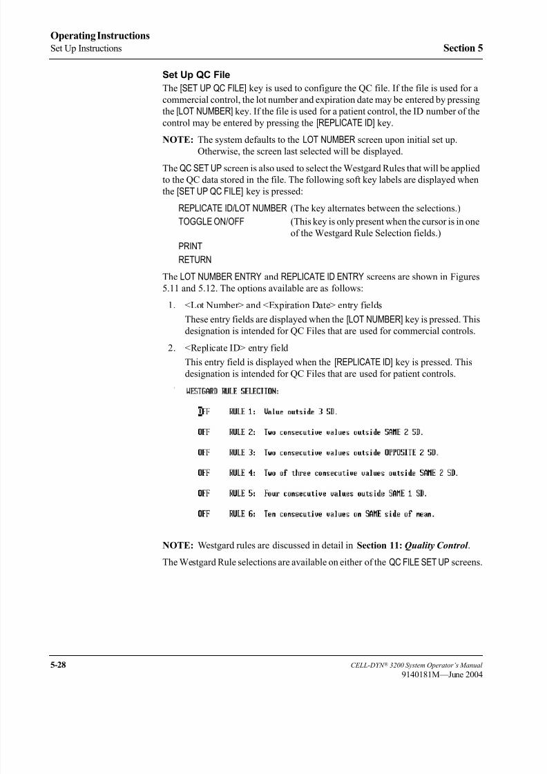
8/21/2019 Equ22-14 CellDyn3200 Op Man
http://slidepdf.com/reader/full/equ22-14-celldyn3200-op-man 186/690
5-28 CELL-DYN ® 3200 System Operator’s Manual
9140181M—June 2004
Operating Instructions
Set Up Instructions Section 5
Set Up QC File
The [SET UP QC FILE] key is used to configure the QC file. If the file is used for a
commercial control, the lot number and expiration date may be entered by pressing
the [LOT NUMBER] key. If the file is used for a patient control, the ID number of the
control may be entered by pressing the [REPLICATE ID] key.
NOTE: The system defaults to the LOT NUMBER screen upon initial set up.
Otherwise, the screen last selected will be displayed.
The QC SET UP screen is also used to select the Westgard Rules that will be applied
to the QC data stored in the file. The following soft key labels are displayed when
the [SET UP QC FILE] key is pressed:
REPLICATE ID/LOT NUMBER (The key alternates between the selections.)
TOGGLE ON/OFF (This key is only present when the cursor is in one
of the Westgard Rule Selection fields.)
RETURN
The LOT NUMBER ENTRY and REPLICATE ID ENTRY screens are shown in Figures
5.11 and 5.12. The options available are as follows:
1. <Lot Number> and <Expiration Date> entry fields
These entry fields are displayed when the [LOT NUMBER] key is pressed. This
designation is intended for QC Files that are used for commercial controls.
2. <Replicate ID> entry field
This entry field is displayed when the [REPLICATE ID] key is pressed. This
designation is intended for QC Files that are used for patient controls.
3.
NOTE: Westgard rules are discussed in detail in Section 11: Quality Control .
The Westgard Rule selections are available on either of the QC FILE SET UP screens.

8/21/2019 Equ22-14 CellDyn3200 Op Man
http://slidepdf.com/reader/full/equ22-14-celldyn3200-op-man 187/690
CELL-DYN ® 3200 System Operator’s Manual 5-29
9140181H—October 2001
Section 5 Operating Instructions
QC File Set Up
1. Press [QC SET UP MENU] to display the QC SET UP MENU screen.
2. Use the Arrow keys on the keyboard to move the cursor to the desired QC
file.
3. Type the desired alphanumeric file name. (Up to 12 characters may be
entered.)
4. Press the Enter key on the keyboard to save the entry and advance the cursor
to the next QC file.
5. Use the Arrow keys on the keyboard to move the cursor back into the selected
file.
6. Press [SET UP QC FILE] to display the QC FILE SET UP screen.
Figure 5.11 Lot Number Entry Screen

8/21/2019 Equ22-14 CellDyn3200 Op Man
http://slidepdf.com/reader/full/equ22-14-celldyn3200-op-man 188/690
5-30 CELL-DYN ® 3200 System Operator’s Manual
9140181H—October 2001
Operating Instructions
Set Up Instructions Section 5
To Enter Lot Number Data
1. If necessary, from the QC FILE SET UP screen, press [LOT NUMBER] to display
the <Lot Number> and <Expiration Date> entry fields.
2. The cursor is in the <Lot Number> entry field. Type the lot number and press
the Enter key on the keyboard to save the entry and advance the cursor to the
<Expiration Date> entry field.
3. Type the expiration date in the format indicated using one or two digits. This
is the same format selected on the DATE/TIME SET UP screen. Separate the
digits with a slash (/) or a period (.).
4. Press the Enter key on the keyboard to save the entry and advance the cursor
to the <Westgard Rule Selection> entry fields.
5. Use the arrow keys on the keyboard to position the cursor at the desired
Westgard® Rule.
6. Press [TOGGLE ON/OFF] to enable the rule and advance the cursor.
7. Repeat steps 5 and 6 until all desired rule selections have been made.
8. If desired, press [PRINT] to obtain a printout of the entries.9. Press [RETURN] to return to the QC FILE SET UP screen.
Figure 5.12 Replicate ID Entry Screen

8/21/2019 Equ22-14 CellDyn3200 Op Man
http://slidepdf.com/reader/full/equ22-14-celldyn3200-op-man 189/690
CELL-DYN ® 3200 System Operator’s Manual 5-31
9140181H—October 2001
Section 5 Operating Instructions
To Enter Replicate ID Data
1. If necessary, from the QC FILE SET UP screen, press [REPLICATE ID] to display
the <Replicate Id> entry field.
2. The cursor is in the <Replicate ID> entry field. Type the sample ID number
(up to 12 alphanumeric characters may be entered) and press the Enter key
on the keyboard to save the entry and advance the cursor to the<Westgard Rule Selection> entry fields.
3. Select the Westgard® Rules as directed in the To Enter Lot Number Data
procedure.
Customize Display
The [CUSTOMIZE DISPLAY] key in the QC SET UP menu is used to customize the
display of information in the QC logs. Figure 5.13 shows the CUSTOMIZE QCDISPLAY screen with the standard groups displayed. Figure 5.14 shows the
CUSTOMIZE QC DISPLAY screen where the WBC and RBC groups have been
customized.
The CUSTOMIZE QC DISPLAY screen and the following key labels are displayedwhen the [CUSTOMIZE DISPLAY] key is pressed:
SELECT PARAMETER
STANDARD GROUPS
RETURN
The screen displays a matrix of 4 rows of parameters that are currently selected in
Groups 1 through 4. A list of all available parameters is displayed under the matrix.
The standard groups, which include predetermined parameter sets, are identified as
follows:
Group 1 WBC parameters
Group 2 RBC parametersGroup 3 PLT parameters
Group 4 WBC Diff parameters
On the CUSTOMIZE QC DISPLAY screen, Parameter Group 1 is displayed (in the
order indicated from left to right) on the first VIEW QC LOG screen. The remaining
groups are displayed on subsequent screens that are accessed by pressing the Right
Arrow key on the keyboard. The Left Arrow key is used to page back through the
screens to the first screen.
The [STANDARD GROUPS] key is used to select a predetermined group of
parameters that will be placed on a designated page. The display may be
customized by selecting the individual parameters, standard groups of parameters,
or a combination of the two.

8/21/2019 Equ22-14 CellDyn3200 Op Man
http://slidepdf.com/reader/full/equ22-14-celldyn3200-op-man 190/690
5-32 CELL-DYN ® 3200 System Operator’s Manual
9140181H—October 2001
Operating Instructions
Set Up Instructions Section 5
Figure 5.13 Customize QC Display Screen
Figure 5.14 Customize QC Display Screen Showing Standard Groups

8/21/2019 Equ22-14 CellDyn3200 Op Man
http://slidepdf.com/reader/full/equ22-14-celldyn3200-op-man 191/690
CELL-DYN ® 3200 System Operator’s Manual 5-33
9140181H—October 2001
Section 5 Operating Instructions
To Customize QC Log Display
1. Select a file from the QC SET UP menu screen by moving the cursor to the
desired file.
2. Press [CUSTOMIZE DISPLAY] to display the CUSTOMIZE QC DISPLAY screen
for the selected file.
3. If necessary, press [CUSTOM PLACEMENT] to display the CUSTOMIZE QCDISPLAY screen and the [SELECT PARAMETER] key.
4. Use the Arrow keys on the keyboard to move the cursor to the desired
parameter in the listing under the matrix.
5. Press [SELECT PARAMETER]. The selected parameter is highlighted and the
cursor moves to the first position in Group 1.
NOTE: The key label changes to [PLACE PARAMETER] and a [CANCELSELECTION] key is displayed.
6. If necessary, use the Arrow keys on the keyboard to move the cursor to the
desired location and press [PLACE PARAMETER].
NOTE: When the [PLACE PARAMETER] key is pressed, the selected parameter is displayed in the position indicated by the cursor and
the cursor is then advanced to the next parameter in the listing
under the matrix.
7. Repeat steps 4–6 until all selections have been made.
8. If desired, press the Print screen key on the keyboard to obtain a printout of
the selected groups.
9. Press [RETURN] to return to the QC SET UP menu screen.
10. Repeat this procedure to customize the display for other QC logs.
Standard Groups
Predetermined groups of parameters, called Standard Groups, may be selected by
pressing the [STANDARD GROUPS] key (refer to Figure 5.14). When the [STANDARDGROUPS] key is pressed, the following soft key labels are displayed:
WBC GROUP
RBC GROUP
PLT GROUP
DIFF GROUP
LATEX SET
CUSTOM PLACEMENT*
RETURN
* This key is used to return to the CUSTOMIZE QC DISPLAY screen for operator-
selected placement.

8/21/2019 Equ22-14 CellDyn3200 Op Man
http://slidepdf.com/reader/full/equ22-14-celldyn3200-op-man 192/690
5-34 CELL-DYN ® 3200 System Operator’s Manual
9140181H—October 2001
Operating Instructions
Set Up Instructions Section 5
Customize QC Log Display (Standard Groups)
1. Select a file from the QC SET UP menu screen by moving the cursor to the
desired file.
2. Press [CUSTOMIZE DISPLAY] to display the CUSTOMIZE QC DISPLAY screen
for the selected file.
3. Press [STANDARD GROUPS] to display the CUSTOMIZE QC DISPLAY screen
and key labels for Standard Groups.
4. Use the Arrow keys on the keyboard to move the cursor to the desired group
(1–4) location.
NOTE: This number indicates the order in which the group of parameters
will be displayed (Group 1 on the first screen, Group 2 on the
second, etc.).
5. Press the soft key corresponding to the desired parameter group. This group
is displayed in the position indicated by the cursor.
6. Repeat steps 4 and 5 until all desired groups have been selected.
7. If desired, press the Print screen key on the keyboard to obtain a printout ofthe configuration.
8. Press [RETURN] to return to the QC SET UP menu screen.
9. Repeat this procedure to select standard groups for other QC logs.
Latex Set
This key is intended to be used by Abbott Service personnel only. If the [LATEXSET] key is pressed, parameters in all groups will be affected. The [LATEX SET] key
is available from the CUSTOMIZE QC DISPLAY screen for Standard Groups. This
key is used to customize the QC file to store information generated by latex
particles. Information is stored for each of the four angles of scatter which are used
to determine the differential.

8/21/2019 Equ22-14 CellDyn3200 Op Man
http://slidepdf.com/reader/full/equ22-14-celldyn3200-op-man 193/690
CELL-DYN ® 3200 System Operator’s Manual 5-35
9140181H—October 2001
Section 5 Operating Instructions
Figure 5.15 Customize QC Printout Screen
Customize Printout
The [CUSTOMIZE PRINTOUT] key in the QC SET UP menu is used to customize the
printout format for the QC logs. (See Figure 5.15.) The following soft key labels
are displayed when the [CUSTOMIZE PRINTOUT] key is pressed:
SELECT PARAMETER (Toggles to PLACE PARAMETER when pressed)STANDARD SELECTION
RETURN
The CUSTOMIZE QC PRINTOUT screen displays the group of parameters that is
currently selected. A list of all available parameters is displayed under the group.
Standard Selection
The [STANDARD SELECTION] key is used to automatically arrange the parameters
in predetermined print groups (see Figure 5.14).
Select Parameter
The [SELECT PARAMETER/PLACE PARAMETER] key is used to customize the QCLog printout.
1. Select a file from the QC SET UP menu screen by moving the cursor to the
desired file.
2. Press [CUSTOMIZE PRINTOUT] to display the CUSTOMIZE QC PRINTOUT
screen for the selected file.
3. Use the Arrow keys on the keyboard to move the cursor to the desired
parameter in the list under the printout group.

8/21/2019 Equ22-14 CellDyn3200 Op Man
http://slidepdf.com/reader/full/equ22-14-celldyn3200-op-man 194/690
5-36 CELL-DYN ® 3200 System Operator’s Manual
9140181H—October 2001
Operating Instructions
Set Up Instructions Section 5
4. Press [SELECT PARAMETER]. The selected parameter is highlighted and the
cursor moves to the first position in the group.
NOTE: The key label changes to [PLACE PARAMETER] and a [CANCELSELECTION] key is displayed.
5. If necessary, use the Arrow keys on the keyboard to move the cursor to the
desired location and press [PLACE PARAMETER].
NOTE: When the [PLACE PARAMETER] key is pressed, the selected
parameter is displayed in the position indicated by the cursor, the
cursor advances to the next parameter in the list under the printout
group, and the key label changes back to [SELECT PARAMETER].
6. Repeat steps 3–5 until all entries have been made.
7. If desired, press the Print Screen key on the keyboard to obtain a printout of
the configuration.
8. Press [RETURN] to return to the QC SET UP menu screen.
9. Repeat this procedure to customize the printout for other QC logs.
Figure 5.16 Operation Set Up Menu Screen
Feb 23, 2001

8/21/2019 Equ22-14 CellDyn3200 Op Man
http://slidepdf.com/reader/full/equ22-14-celldyn3200-op-man 195/690
CELL-DYN ® 3200 System Operator’s Manual 5-37
9140181H—October 2001
Section 5 Operating Instructions
Operation Set Up Menu
The OPERATION SET UP MENU screen (see Figure 5.16) allows the operator to
select screen colors, the type of bar code used, and to configure the transmission to
an on-line (host) computer. The following soft key labels are displayed when the
[OPERATION SET UP] key is pressed:
TURN ON RETIC PKG
LANGUAGE
SELECT COLOR
BAR CODE SET UP
COMPUTER SET UP
RETURN
Figure 5.17 Language Selection Screen
Language Selection < English (default language)>
The LANGUAGE SELECTION screen, shown in Figure 5.17, will allow the user to
select one of the following non-English languages for display and printout:
FrenchGerman
Italian
Japanese
Portuguese
Spanish

8/21/2019 Equ22-14 CellDyn3200 Op Man
http://slidepdf.com/reader/full/equ22-14-celldyn3200-op-man 196/690
5-38 CELL-DYN ® 3200 System Operator’s Manual
9140181H—October 2001
Operating Instructions
Set Up Instructions Section 5
The following soft keys are displayed when the [LANGUAGE] key is pressed:
ENGLISH (used to return to the default language)
English (name of currently displayed language)
NEXT LANGUAGE
RETURNPressing the capitalized [ENGLISH] soft key allows the operator to return to English
which is the default language.
The name of the currently displayed language is displayed next to [ENGLISH]. For
example, if English is the displayed language, then [English] will be displayed in the
second key position. The name of each language is displayed using the spelling
convention of the host language: French is displayed as [français], German as
[deutsch], and Spanish as [español].
Pressing the language key affects the display and printout of soft keys, bulletin and
screen messages, and demographic data; it does not effect the measurement process
or other functional aspects of the program.
Pressing the [NEXT LANGUAGE] soft key will allow the user to scroll through the
available languages.
To Change the Language
1. In the OPERATION SET UP MENU, press [LANGUAGE].
2. Press [NEXT LANGUAGE] to scroll through the list of languages available on
the instrument.
3. When the desired language is displayed in the second soft key label position,
press [RETURN] to save the selection and return to the OPERATION SET UPMENU.
4. If desired, attach a keyboard appropriate to the language selected.CAUTION: If a different keyboard will be attached to the instrument
because of the change in language, the instrument (Analyzer only) should
first be turned OFF before the old keyboard is unplugged and the new
keyboard is attached. This will prevent accidental injury to the operator or
damage to the instrument.
NOTE: Permanent language selection must be made during installation. If the
instrument is re-booted, it will revert to the installed language selection.

8/21/2019 Equ22-14 CellDyn3200 Op Man
http://slidepdf.com/reader/full/equ22-14-celldyn3200-op-man 197/690
CELL-DYN ® 3200 System Operator’s Manual 5-39
9140181H—October 2001
Section 5 Operating Instructions
Figure 5.18 Select Color Screen
Select Color
The SELECT COLOR screen, shown in Figure 5.18, allows the user to select various
colors for displaying parameter data and other information on the screen. The
following soft keys are displayed when the [SELECT COLOR] key is pressed:
RESTORE PREVIOUSRESTORE DEFAULT
RETURN
Color Reference
Main Body 1 Main screen
Main Body 2 Flags
Main Body 3 Run mode description
Main Body 4 Values below limits
Main Body 5 Values above limits
Main Body 6 Sequence numbers in Data Log
Main Body 7 RBC Histogram/New entry before Enter key is pressed
Main Body 8 PLT Histogram/New entry after Enter key is pressed
Title Block Top center of screen
Inverse Title Title not currently used
Bulletin Alert messages above function keys
Function Keys Soft key descriptions
Cursor Screen cursor

8/21/2019 Equ22-14 CellDyn3200 Op Man
http://slidepdf.com/reader/full/equ22-14-celldyn3200-op-man 198/690
5-40 CELL-DYN ® 3200 System Operator’s Manual
9140181H—October 2001
Operating Instructions
Set Up Instructions Section 5
To Change Color Settings
1. Press [SELECT COLOR] in the OPERATION SET UP MENU.
2. Use the Arrow keys on the keyboard to move the cursor to the desired
location in either the Foreground or Background columns.
3. Enter the number corresponding to the desired color from the list on the left
side of the screen. Press the Enter key to save the entry and move the cursor
to the next position.
NOTE: The one field which cannot be changed is Background for Main
body 1. This background must always remain black.
4. When all desired changes have been made, press [RETURN] to return to the
OPERATION SET UP MENU.
5. If the operator changes a color selection, then wishes to cancel the change and
keep the original setting, pressing [RESTORE PREVIOUS] while this screen is
still displayed will cancel all changes and restore the original color selection.
Pressing [RESTORE DEFAULT] will cause the screen colors to revert to the
configuration set at the factory prior to shipment.

8/21/2019 Equ22-14 CellDyn3200 Op Man
http://slidepdf.com/reader/full/equ22-14-celldyn3200-op-man 199/690
CELL-DYN ® 3200 System Operator’s Manual 5-41
9140181H—October 2001
Section 5 Operating Instructions
Figure 5.19 Bar Code Set Up Screen
Bar Code Set Up
The [BAR CODE SET UP] key is used to select the type of bar code to be read and to
enable or disable the check digit option for the selected bar code. (See Figure 5.19.)
NOTE: For more information about check digits and bar codes, refer to Appendix
A, Bar Codes.
To Set Up Bar Code
1. From the OPERATION SET UP MENU screen, press [BAR CODE SET UP] todisplay the BAR CODE SET UP screen.
2. Type the number for the type of bar code that will be used:
1 — Code 39
2 — Interleaved 2 of 5
3 — CODABAR
4 — Code 128
Press the Enter key on the keyboard to save the entry and advance the cursor
to the Bar Code Check Digit field.
3. Press [TOGGLE ON/OFF] to enable or disable the check digit.
NOTE: The [TOGGLE ON/OFF] key is displayed only when the cursor is
positioned next toBAR CODE CHECK DIGIT.
4. Press [SET UP] to return to the OPERATION SET UP MENU.

8/21/2019 Equ22-14 CellDyn3200 Op Man
http://slidepdf.com/reader/full/equ22-14-celldyn3200-op-man 200/690
5-42 CELL-DYN ® 3200 System Operator’s Manual
9140181K—July 2002
Operating Instructions
Set Up Instructions Section 5
Figure 5.20 Computer Set Up Screen
Computer Set Up Menu
The [COMPUTER SET UP] key is used to display the COMPUTER SET UP screen (see
Figure 5.20) and the following soft key labels:
REINIT INTERFACESTOP TRANSMISS
TOGGLE ON/OFF
SET UP
The CELL-DYN 3200 can transmit data to an on-line computer (Laboratory
Information System) using a direct serial link. Data may be transmitted
automatically as each sample is run or at the operator’s request. The
CELL-DYN 3200 also can receive patient information transmitted to it by the
on-line computer.
The COMPUTER SET UP screen is used to configure the transmission format to meet
the requirements of the Laboratory Information System or on-line computer.
Instructions for using this option are given after the following description of the
soft keys.
Reinit Interface
The [REINIT INTERFACE] key is used to initialize the RS-232 interface for the
displayed transmission configuration after it is entered. The interface is
automatically initialized whenever the [STOP TRANSMISS] key is pressed.
NOTE: Refer to the Interface Specification for complete information on
interfacing.
OFF Auto-transmission of ALTERED parameter data
OFF Auto-transmission of NON-ALTERED parameter data
OFF Auto-transmission of ALTERED graph data
OFF Auto-transmission of NON-ALTERED graph data
OFF Transmission CTS enabled
OFF Auto-transmission of extended histogram records
OFF Auto-transmission of scatter data
8 Transmission of Data bits (7, 8)
1 Transmission Stop bits(1, 2)
0 Transmission Parity (0=None, 1=Odd, 2=Even)
0.3 Transmission time out (0.1 to 9.9)
9600 Computer BaudRate (300,600,1200,2400,4800,9600,19200,38400,56000)
8/21/2019 Equ22-14 CellDyn3200 Op Man
http://slidepdf.com/reader/full/equ22-14-celldyn3200-op-man 201/690
CELL-DYN ® 3200 System Operator’s Manual 5-43
9140181K—July 2002
Section 5 Operating Instructions
Stop Transmiss
The [STOP TRANSMISS] key is used to terminate the current data transmission to an
on-line computer. When the [STOP TRANSMISS] key is pressed, the following soft
key labels are displayed:
CONFIRM STOP
CANCEL STOP
Pressing [CONFIRM STOP] causes the transmission to terminate. Pressing [CANCELSTOP] allows the transmission to continue.
Toggle ON/OFF
The [TOGGLE ON/OFF] key enables or disables the first seven options in the list
displayed on the COMPUTER SET UP screen.
A description of the options available on the COMPUTER SET UP screen is given below:
1. Auto-transmission of ALERTED parameter data
When this option is enabled, a report is automatically transmitted to the LIS
for any sample with flagged parameter results.
2. Auto-transmission of NON-ALERTED parameter data
When this option is enabled, a report is automatically transmitted to the LIS
for any sample without flagged parameter results.
3. Auto-transmission of ALERTED graph data
When this option is enabled, histograms are automatically transmitted to the
LIS for any sample with flagged results.
4. Auto-transmission of NON-ALERTED graph data
When this option is enabled, histograms are automatically transmitted to the
LIS for any sample without flagged results.
5. Transmission CTS enabled
6. Auto-transmission of extended histogram records
When this option is enabled, extended histograms are automatically
transmitted to the LIS.
7. Auto-transmission of scatter data
When this option is enabled, scatter data is automatically transmitted to the
LIS.
8. The remaining options are configured according to the requirements of the
LIS:
TRANSMISSION DATA BITS (7, 8)
TRANSMISSION STOP BITS (1, 2)
TRANSMISSION PARITY (0=NONE, 1=ODD, 2=EVEN)
TRANSMISSION TIME OUT (0.1 to 9.9)
COMPUTER BAUD RATE (300, 600, 1200, 2400, 4800,
9600, 19200, 38400, 56000)
The numbers in parentheses after the options indicate the selections available.
NOTE: Refer to the Interface Specification for complete information on interfacing.
8/21/2019 Equ22-14 CellDyn3200 Op Man
http://slidepdf.com/reader/full/equ22-14-celldyn3200-op-man 202/690
5-44 CELL-DYN ® 3200 System Operator’s Manual
9140181K—July 2002
Operating Instructions
Set Up Instructions Section 5
NOTE: Auto-transmitting extended data uses CPU time during the acquisition
cycle. In order to reduce the time taken by this transmission, auto-
transmission of extended data is only allowed at the baud rates of 38400 and
56000. If there is a need to re-transmit data, this can be done one specimen
at a time from the DISPLAY SPECIMEN menu if the correct baud rate has
been selected and transmission of either extended histograms or extendedscatter plots has been selected.
Computer Set Up Procedure
1. From the OPERATION SET UP MENU, press [COMPUTER SET UP] to display
the COMPUTER SET UP screen.
2. For the first five options on the list, use the Arrow keys on the keyboard to
move the cursor to the desired selection and press [TOGGLE ON/OFF] to enable
or disable the selection.
NOTE: The [TOGGLE ON/OFF] key is displayed when the cursor is
positioned in any of the first five entry fields.
3. For the last five options on the list, type the appropriate information and pressthe Enter key on the keyboard to save the entry and advance the cursor.
4. When all the information has been entered, press [REINIT INTERFACE] toinitialize the interface for the selected configuration.
5. If desired, press the Print Screen key on the keyboard to obtain a printout of
the configuration.
6. Press [SET UP] to return to the OPERATION SET UP MENU screen.
7. Press [RETURN] to return to the SET UP MENU.

8/21/2019 Equ22-14 CellDyn3200 Op Man
http://slidepdf.com/reader/full/equ22-14-celldyn3200-op-man 203/690
CELL-DYN ® 3200 System Operator’s Manual 5-45
9140181H—October 2001
Section 5 Operating Instructions
Figure 5.21 Units Selection Screen
Units Selection Menu
The [UNITS SELECTION] key selects the report units for the indicated parameters.
Units may be selected for each parameter individually or a set of units may be
selected by pressing the appropriate soft key. (See Figure 5.21.) The following soft
key labels are displayed when the [UNITS SELECTION] key is pressed:
USA UNITS
SI UNITS
SI MOD UNITS
SET1 UNITS
SET2 UNITS
SELECT UNITS
RETURN
The units selected by each of the soft keys are shown on the screen display in
Figure 5.21. The following table demonstrates how values are reported for the
same sample under each “units” category.

8/21/2019 Equ22-14 CellDyn3200 Op Man
http://slidepdf.com/reader/full/equ22-14-celldyn3200-op-man 204/690
5-46 CELL-DYN ® 3200 System Operator’s Manual
9140181M—June 2004
Operating Instructions
Set Up Instructions Section 5
* NEU, LYM, MONO, EOS and BASO are reported in the same units as the WBC
** Report Unit is Geometric Standard Deviation
To Change Units Selection
1. From the SET UP MENU screen, press [UNITS SELECTION].
2. Press the appropriate soft key to select the desired units. The group of
selected units is highlighted on the screen.
OR
3. For individual unit selection, use the Arrow keys on the keyboard to move
the cursor to the desired units.
4. Press [SELECT UNITS] to enter the selection. The chosen selection ishighlighted on the display.
5. Use the Arrow keys on the keyboard to move the cursor to the next unit to be
selected.
6. Repeat steps 4 and 5 until all selections have been made.
7. If desired, press the Print Screen key on the keyboard to obtain a printout of
the selected units.
8. Press [RETURN] to return to the SET UP MENU screen.
Table 5.1 Report Units
Parameter
USA SI SI MOD SET1 SET2
Value Units Value Units Value Units Value Units Value Units
WBC* 5.32 K/µL 5.32 G/L 5.32 10e9/L 5.32 10e3/µL 53.2 10e2/µL
RBC 5.15 M/µL 5.15 T/L 5.15 10e12/L 5.15 10e6/µL 515. 10e4/µL
HGB 16.2 g/dL 162 g/L 10.1 mmol/L 162 g/L 16.2 g/dL
HCT 47.6 % 0.476 L/L 0.476 L/L 47.6 % 47.6 %
MCV 92.3 fL 92.3 fL 92.3 fL 92.3 fL 92.3 fL
MCH 31.5 pg 31.5 pg 1.96 fmol 31.5 pg 31.5 pg
MCHC 34.1 g/dL 341 g/L 21.2 mmol/L 341 g/L 34.1 g/dL
RDW 12.5 % 12.5 %CV 12.5 %CV 12.5 %CV 12.5 %
PLT 323 K/µL 323 G/L 323 10e9/L 323 10e3/µL 32.3 10e4/µL
MPV 8.26 fL 8.26 fL 8.26 fL 8.26 fL 8.26 fL
PCT 0.267 % 2.67 mL/L 2.67 mL/L 0.267 % 0.267 %
PDW** 17.5 10GSD 17.5 10GSD 17.5 10GSD 17.5 10GSD 17.5 10GSD
RETIC
ABS51.5 K/µL 51.5 G/L 51.5 10e9/L 51.5 10e3/µL 5.15 10e4/µL

8/21/2019 Equ22-14 CellDyn3200 Op Man
http://slidepdf.com/reader/full/equ22-14-celldyn3200-op-man 205/690
CELL-DYN ® 3200 System Operator’s Manual 5-47
9140181H—October 2001
Section 5 Operating Instructions
Customize Report
The [CUSTOMIZE REPORT] key is used to customize displayed and/or printed
reports. When the [CUSTOMIZE REPORT] key is pressed, the screen that was
displayed last will appear (Graphics Printer is the default screen).
Customize PrintoutThe [CUSTOMIZE PRINTOUT] key is used to customize the printout for the Graphics
Printer and the Ticket Printer. For ease of explanation, the two printer types are
discussed individually. Specific instructions are given for customizing a report for
the graphics printer, for a blank ticket, and for a pre-printed ticket. When the
[CUSTOMIZE PRINTOUT] key is pressed, some of the soft key labels change with the
type of printer that is selected. The following soft key labels are displayed when
the key is pressed:
GRAPHICS PRINTER/TICKET PRINTER (The key alternates between the selections.)
CUSTOMIZE DISPLAY
STOP PRINTINGCUSTOMIZE HEADER
TOGGLE ON/OFF
SET UP
When the [CUSTOMIZE PRINTOUT] key is pressed, the screen that was used for the
last entry (graphics printer or ticket printer) is displayed. A brief description of the
function of the soft keys is given in this section. For ease of explanation, the keys
are grouped according to the type of printer selected.
When the [TICKET PRINTER] key is pressed, the following soft key label is also
displayed:
BLANK TICKET/PRE-PRNTD TICKET (The key label alternates between the selections.)
The [CUSTOMIZE DISPLAY] key is used to customize the display as discussed in the
next section.
The [STOP PRINTING] key is used to stop printing that is in progress. When the
[STOP PRINTING] key is pressed, the following soft key labels are displayed:
CONFIRM STOP
CANCEL STOP
The [CANCEL STOP] key cancels the Stop Printing command. If [CONFIRM STOP] is
pressed, the print buffer (the memory area where the material is stored while
awaiting printing) is cleared and the bulletin line displays the message:
PRINTING STOPPED. RESET PAPER TO THE TOP OF THE PAGE
Two additional keys are displayed when the [CUSTOMIZE HEADER] key is pressed:
RESTORE HEADER
BLANK HEADER
The [TOGGLE ON/OFF] key enables or disables the option selected by the position
of the cursor. The key label is not displayed when a numeric entry is required.
The [SET UP] key is used to return to the SET UP MENU screen.

8/21/2019 Equ22-14 CellDyn3200 Op Man
http://slidepdf.com/reader/full/equ22-14-celldyn3200-op-man 206/690
5-48 CELL-DYN ® 3200 System Operator’s Manual
9140181H—October 2001
Operating Instructions
Set Up Instructions Section 5
Figure 5.22 Customize Printed Report Screen for the Graphics Printer
Graphics Printer
When the [GRAPHICS PRINTER] key is pressed, the CUSTOMIZE PRINTED REPORTscreen for the Graphics Printer is displayed. (See Figure 5.22.) A description of the
options available on the CUSTOMIZE PRINTED REPORT screen is given below:
1. AUTO-PRINT RESULTS FOR ALERTED SPECIMENSWhen this option is enabled, a report is automatically printed for any sample
with flagged results.
2. AUTO-PRINT RESULTS FOR NON-ALERTED SPECIMENS
When this option is enabled, a report is automatically printed for any sample
without flagged results.
3. PRINT GRAPHS FOR ALERTED SPECIMENS ONLY
When this option is enabled, scatterplots and histograms are printed only for
samples with flagged results.
4. PRINT PCT, PDW RESULTS
When this option is enabled, the results for PCT and PDW are printed on thereport.
NOTE: Clinical significance has not been established for these parameters.
Therefore, they are not reportable.
5. PRINT X-B RBC PROGRAM STATUS
When this option is enabled, the status of the X-B RBC program is printed on
the report. The X-B status (for example, X-B RBC: 13/OUT2) is printed
below the Status Box.

8/21/2019 Equ22-14 CellDyn3200 Op Man
http://slidepdf.com/reader/full/equ22-14-celldyn3200-op-man 207/690
CELL-DYN ® 3200 System Operator’s Manual 5-49
9140181H—October 2001
Section 5 Operating Instructions
6. PRINT X-B WBC PROGRAM STATUS
When this option is enabled, the status of the X-B WBC program is printed
on the report. The X-B status (for example, X-B WBC: 13/OUT2) is printed
below the Status Box.
7. PRINT INTERPRETIVE REPORT
When this option is enabled, the Interpretive Report messages are printed on
the report. These messages are generated when results exceed the Patient
Limits and/or instrument-generated flags are present. Refer to Section 3:
Principles of Operation; Subsection: Operational Messages and Data
Flagging for an explanation of the Interpretive Report messages. (Also see
the [PATIENT LIMITS] key discussion earlier in this section.)
8. PRINT LIMITS REPORT
When this option is enabled, the Patient Limits set that was applied to the
results is printed on the report.
9. PRINT MANUAL DIFFERENTIAL GRID FOR ALERTED SPECIMENS
When this option is enabled, a grid that can be used to report a manual
Differential is printed on the report for any specimen that is flagged.
10. PRINT MANUAL DIFFERENTIAL GRID FOR NON-ALERTED
SPECIMENS
When this option is enabled, a grid that can be used to report a manual
Differential is printed on the report for any specimen that is not flagged.
11. LINE-FEEDS PER PAGE FOR GRAPHICS PRINTER (1 to 99)
This option is used to select the size of the printed report.
12. COLOR PRINTING
When this option is enabled, a color printout can be obtained on theCELL-DYN 3200 by pressing the [COLOR PRINT] key.
To Customize the Graphics Report
1. Go to the Graphics Printer set up section of the CUSTOMIZE PRINTEDREPORT screen (refer to Figure 5.22).
2. Use the Arrow keys on the keyboard to move the cursor to the desired
selection.
3. Press [TOGGLE ON/OFF] to enable or disable any of the ON/OFF selections.
4. Repeat steps 2 and 3 until all selections have been made.
5. A numeric entry is required for theLINE-FEEDS PER PAGE FOR
GRAPHICS PRINTER field. Type the desired number of line-feeds in theentry field and press the Enter key on the keyboard to save the entry and
advance the cursor. (An 8.5" x 11" sheet of paper has 66 lines per page.)
6. If desired, press the Print Screen key on the keyboard to obtain a printout of
the selections.
7. If desired, press [SET UP] to return to the SET UP MENU screen, or continue
with the following procedure for customizing the header.

8/21/2019 Equ22-14 CellDyn3200 Op Man
http://slidepdf.com/reader/full/equ22-14-celldyn3200-op-man 208/690
5-50 CELL-DYN ® 3200 System Operator’s Manual
9140181H—October 2001
Operating Instructions
Set Up Instructions Section 5
Figure 5.23 Customize Printout Header Screen for the Graphics Report
Customize Header
The [CUSTOMIZE HEADER] key is used to customize the header for the graphics
report. (See Figure 5.23.) Any report printed in a graphics format will be printed
with this header. The following soft key labels are displayed when the [CUSTOMIZEHEADER] key is pressed:
RESTORE HEADER
BLANK HEADER
CUSTOMIZE DISPLAY
CUSTOMIZE PRINTOUT
SET UP
Restore Header
The [RESTORE HEADER] key is used to restore the header to the previous entry.
This key is only functional immediately after a new header has been entered. Once
a new header is entered and the CUSTOMIZE PRINTOUT HEADER screen has been
exited, the previous header is removed from the memory.
Blank Header
The [BLANK HEADER] key is used to erase the current header.

8/21/2019 Equ22-14 CellDyn3200 Op Man
http://slidepdf.com/reader/full/equ22-14-celldyn3200-op-man 209/690
CELL-DYN ® 3200 System Operator’s Manual 5-51
9140181H—October 2001
Section 5 Operating Instructions
To Customize the Graphics Header
1. From any CUSTOMIZE PRINTED REPORT screen, press [CUSTOMIZE HEADER] to display the CUSTOMIZE PRINTOUT HEADER screen. Use the Arrow keys to
skip a field.
2. Type the desired number of lines for the header in the indicated field. The
header can include up to four lines.
3. Press the Enter key on the keyboard to save the entry and advance to the next
entry field.
4. Press [TOGGLE ON/OFF] to enable or disable the PRINT CURRENT DATE/
TIME AND SOFTWARE VERSION option.
5. In the header box field, type the information to be displayed on the first line
of the header. Each line holds 77 characters. Press the Enter key to move to
the next header line.
NOTE: The number of lines of data in the header box cannot exceed the
number of lines indicated in the first field. For example, if 3 were
input in the first field, then a maximum of 3 lines will be accepted
in the header box. The operator may type in 4 lines of data, but only
the first three lines will be saved when the operator exists this
screen. (Existing information may be typed over or an existing
header may be deleted by pressing the [BLANK HEADER] key.)
NOTE: The numbers displayed above the header box on the screen indicate
the position of the header on the printed page. For example,
centering the header/information under the number 4 centers the
header on the page. Each line can be positioned independently of
the other lines in the header box. Use the Space Bar on the
keyboard to position the cursor for typing.
6. Press [SET UP] to return to the SET UP MENU screen.
Ticket Printer
Two options are available when the [TICKET PRINTER] key is pressed:
BLANK TICKET/
PRE-PRNTD TICKET (The key alternates between the selections.)
The [PRE-PRNTD TICKET] key is used to customize the printed report for a
pre-printed ticket. The [BLANK TICKET] key is used to customize the printed report
for a blank ticket.
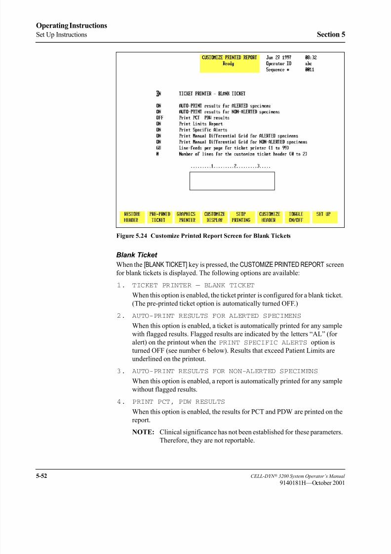
8/21/2019 Equ22-14 CellDyn3200 Op Man
http://slidepdf.com/reader/full/equ22-14-celldyn3200-op-man 210/690
5-52 CELL-DYN ® 3200 System Operator’s Manual
9140181H—October 2001
Operating Instructions
Set Up Instructions Section 5
Figure 5.24 Customize Printed Report Screen for Blank Tickets
Blank Ticket
When the [BLANK TICKET] key is pressed, the CUSTOMIZE PRINTED REPORT screen
for blank tickets is displayed. The following options are available:
1. TICKET PRINTER — BLANK TICKET
When this option is enabled, the ticket printer is configured for a blank ticket.
(The pre-printed ticket option is automatically turned OFF.)
2. AUTO-PRINT RESULTS FOR ALERTED SPECIMENS
When this option is enabled, a ticket is automatically printed for any sample
with flagged results. Flagged results are indicated by the letters “AL” (for
alert) on the printout when the PRINT SPECIFIC ALERTS option is
turned OFF (see number 6 below). Results that exceed Patient Limits are
underlined on the printout.
3. AUTO-PRINT RESULTS FOR NON-ALERTED SPECIMENS
When this option is enabled, a report is automatically printed for any sample
without flagged results.
4. PRINT PCT, PDW RESULTS
When this option is enabled, the results for PCT and PDW are printed on the
report.
NOTE: Clinical significance has not been established for these parameters.
Therefore, they are not reportable.

8/21/2019 Equ22-14 CellDyn3200 Op Man
http://slidepdf.com/reader/full/equ22-14-celldyn3200-op-man 211/690
CELL-DYN ® 3200 System Operator’s Manual 5-53
9140181H—October 2001
Section 5 Operating Instructions
5. PRINT LIMITS REPORT
When this option is enabled, the Patient Limits set that was applied to the
results is printed on the report.
6. PRINT SPECIFIC ALERTS
When this option is enabled, the specific flag (BANDS, LRI, etc.) replacesthe “AL” on the printout.
7. PRINT MANUAL DIFFERENTIAL GRID FOR ALERTED SPECIMENS
When this option is enabled, a grid that can be used to report a manual
Differential is printed on the report for any specimen that is flagged.
8. PRINT MANUAL DIFFERENTIAL GRID FOR NON-ALERTED
SPECIMENS
When this option is enabled, a grid that can be used to report a manual
Differential is printed on the report for any specimen that is not flagged.
9. LINE-FEEDS PER PAGE FOR TICKET PRINTER (1 to 99)
This option is used to select the size of the printed report. (A blank tickettypically has 68 lines.)
10. NUMBER OF LINES FOR THE CUSTOMIZE TICKET HEADER
(0 to 2)
This option is used to select the number of lines for the header on the blank
ticket. The numbers across the top of the header can be used to center the
header information on the ticket. Centering the information under the number
2 centers it on the ticket.
To Customize a Blank Ticket
1. If the Blank Ticket section of the CUSTOMIZE PRINTED REPORT screen is not
displayed, press [BLANK TICKET].
2. Use the Arrow keys on the keyboard to move the cursor to the desired
selection.
3. Press [TOGGLE ON/OFF] to enable or disable the selection.
4. Repeat step 3 until all ON/OFF selections have been made.
5. A numeric entry is required for theLINE-FEEDS PER PAGE FOR
TICKET PRINTER field (A blank ticket typically has 68 lines) and the
NUMBER OF LINES FOR THE CUSTOMIZE TICKET HEADER field.
6. Type the desired number of line-feeds in the entry field and press the Enter
key on the keyboard to save the entry and advance the cursor.
7. Type the desired number of lines for the header (a maximum of 2 lines) and press the Enter key on the keyboard to save the entry and advance the cursor
to the header box field.
8. With the cursor in the header box, type the first line of the header and press
the Enter key on the keyboard to save the entry and advance the cursor. Each
line holds 35 characters. If desired, type a second line and press the Enter key
on the keyboard to save the entry and advance the cursor.
NOTE: The number of lines of data in the header box cannot exceed the
number of lines entered in step 8 above. For example, if 1 were
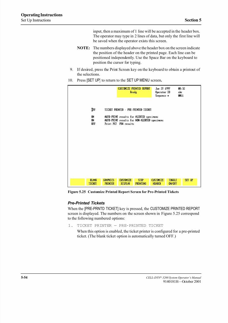
8/21/2019 Equ22-14 CellDyn3200 Op Man
http://slidepdf.com/reader/full/equ22-14-celldyn3200-op-man 212/690
5-54 CELL-DYN ® 3200 System Operator’s Manual
9140181H—October 2001
Operating Instructions
Set Up Instructions Section 5
input, then a maximum of 1 line will be accepted in the header box.
The operator may type in 2 lines of data, but only the first line will
be saved when the operator exists this screen.
NOTE: The numbers displayed above the header box on the screen indicate
the position of the header on the printed page. Each line can be
positioned independently. Use the Space Bar on the keyboard to position the cursor for typing.
9. If desired, press the Print Screen key on the keyboard to obtain a printout of
the selections.
10. Press [SET UP] to return to the SET UP MENU screen.
Figure 5.25 Customize Printed Report Screen for Pre-Printed Tickets
Pre-Printed Tickets
When the [PRE-PRNTD TICKET] key is pressed, the CUSTOMIZE PRINTED REPORT
screen is displayed. The numbers on the screen shown in Figure 5.25 correspond
to the following numbered options:
1. TICKET PRINTER — PRE-PRINTED TICKETWhen this option is enabled, the ticket printer is configured for a pre-printed
ticket. (The blank ticket option is automatically turned OFF.)

8/21/2019 Equ22-14 CellDyn3200 Op Man
http://slidepdf.com/reader/full/equ22-14-celldyn3200-op-man 213/690
CELL-DYN ® 3200 System Operator’s Manual 5-55
9140181H—October 2001
Section 5 Operating Instructions
2. AUTO-PRINT RESULTS FOR ALERTED SPECIMENS
When this option is enabled, results for flagged specimens are automatically
printed as tickets are inserted in the printer. Flagged results are marked with
an asterisk (*).
3. AUTO-PRINT RESULTS FOR NON-ALERTED SPECIMENS
When this option is enabled, results for specimens that are not flagged are
automatically printed as tickets are inserted in the printer.
4. PRINT PCT, PDW RESULTS
When this option is enabled, the PCT and PDW are printed on the ticket.
NOTE: Clinical significance has not been established for these parameters.
Therefore, they are not reportable.
To Customize the Pre-Printed Ticket
1. Go to the Ticket Printer - Pre-printed Ticket section of the CUSTOMIZEPRINTED REPORT screen (refer to Figure 5.25).
2. Use the arrow keys on the keyboard to move the cursor to the desired option.
3. Press [TOGGLE ON/OFF] to enable or disable the selected option.
4. Repeat steps 2 and 3 until all selections have been made.
5. If desired, press the Print Screen key on the keyboard to obtain a printout of
the selections.
6. Press [SET UP] to return to the SET UP MENU screen.
Customize Displayed Report
Customized displays can be established for each of the four parameter sets. The
CUSTOMIZE DISPLAYED REPORT screen (see Figure 5.26) for the indicated
parameter set (in this case PARAM SET 1) and the following soft key labels aredisplayed when the [CUSTOMIZE DISPLAY] key in the CUSTOMIZE PRINTEDREPORT screen is pressed:
PARAM SET 1*
PARAM SET 2*
PARAM SET 3*
PARAM SET 4*
CUSTOMIZE PRINTOUT
CUSTOMIZE HEADER/CANCEL GRAPH (The key label alternates between the selections.)
SELECT GRAPH/PLACE GRAPH (The key label alternates between the selections.)
SET UP
*The soft key for the displayed parameter set is blanked out.
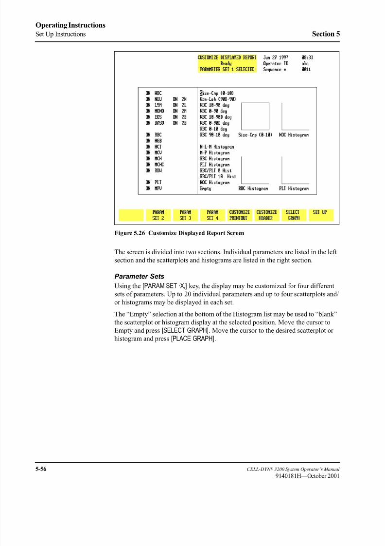
8/21/2019 Equ22-14 CellDyn3200 Op Man
http://slidepdf.com/reader/full/equ22-14-celldyn3200-op-man 214/690
5-56 CELL-DYN ® 3200 System Operator’s Manual
9140181H—October 2001
Operating Instructions
Set Up Instructions Section 5
Figure 5.26 Customize Displayed Report Screen
The screen is divided into two sections. Individual parameters are listed in the left
section and the scatterplots and histograms are listed in the right section.
Parameter Sets
Using the [PARAM SET “X”] key, the display may be customized for four differentsets of parameters. Up to 20 individual parameters and up to four scatterplots and/
or histograms may be displayed in each set.
The “Empty” selection at the bottom of the Histogram list may be used to “blank”
the scatterplot or histogram display at the selected position. Move the cursor to
Empty and press [SELECT GRAPH]. Move the cursor to the desired scatterplot or
histogram and press [PLACE GRAPH].

8/21/2019 Equ22-14 CellDyn3200 Op Man
http://slidepdf.com/reader/full/equ22-14-celldyn3200-op-man 215/690
CELL-DYN ® 3200 System Operator’s Manual 5-57
9140181H—October 2001
Section 5 Operating Instructions
To Customize the Display Screen
1. From the SET UP MENU screen, press [CUSTOMIZE REPORT] and if necessary,
press [CUSTOMIZE DISPLAY] to display a parameter set.
2. If desired, press [PARAM SET “X”] to select a different parameter set.
3. Use the Arrow keys on the keyboard to move the cursor to the desired
parameter in the list displayed on the left section of the screen.
4. Press [TOGGLE PARAMETER] to turn the display off or on and advance the
cursor to the next parameter. The cursor moves through the entire list of
parameters in this section of the screen and, when at the bottom, returns to
the top of this list.
NOTE: The [TOGGLE PARAMETER] key is displayed only when the cursor
is positioned in the list of individual parameters displayed on the
left side of the screen.
5. Repeat steps 3 and 4 until all parameter selections have been made. Use the
Right Arrow key to move the cursor to the next section.
6. Use the Arrow keys to move the cursor to the desired scatterplot orhistogram.
7. Press [SELECT GRAPH] to select it. The scatterplot or histogram name is
highlighted and the cursor moves to a display position. The key label changes
to [PLACE GRAPH] and the [CANCEL GRAPH] key is displayed.
8. If necessary, use the Arrow keys on the keyboard to move the cursor to the
desired display position.
9. Press [PLACE GRAPH] to display the selection at the indicated position. The
cursor moves to the next scatterplot or histogram in the list.
10. Repeat steps 6 through 9 until all selections have been made for the current
Parameter Set.
11. If desired, press the Print Screen key on the keyboard to obtain a printout ofthe selected Parameter Set.
12. Press [PARAM SET “X”] to select another Parameter set and repeat steps 3
through 11 to customize the display for it.
13. Press [SET UP] to return to the SET UP MENU screen.

8/21/2019 Equ22-14 CellDyn3200 Op Man
http://slidepdf.com/reader/full/equ22-14-celldyn3200-op-man 216/690
5-58 CELL-DYN ® 3200 System Operator’s Manual
9140181H—October 2001
Operating Instructions
Set Up Instructions Section 5
Interpretive Report Messages
If the PRINT INTERPRETIVE REPORT option on the CUSTOMIZE PRINTEDREPORT screen for the Graphics Printer is enabled, Interpretive Report messages
are printed on the report. Some of these messages are generated from the
information entered for the Patient Limits. The following messages are generated
by specimen results which exceed the Patient Limits:
WBC Messages
Leukopenia — result exceeds the lower limit for WBC
Leukocytosis — result exceeds the upper limit for WBC
Neutropenia — result exceeds the lower limit for Neutrophil absolute number
Neutrophilia — result exceeds the upper limit for Neutrophil absolute number
Lymphopenia — result exceeds the lower limit for Lymphocyte absolute number
Lymphocytosis — result exceeds the upper limit for Lymphocyte absolute number
Monocytosis — result exceeds the upper limit for Monocyte absolute number
Eosinophilia — result exceeds the upper limit for Eosinophil absolute number
Basophilia — result exceeds the upper limit for Basophil absolute number
RBC Messages
Anemia — result exceeds the lower limit for RBCs
Polycythemia — result exceeds the upper limit for RBCs
Microcytic RBC — result exceeds the lower limit for MCV
Macrocytic RBC — result exceeds the upper limit for MCV
Hypochromic — result exceeds the lower limit for MCHC
Hyperchromic — result exceeds the upper limit for MCHC
Anisocytosis — result exceeds the upper limit for RDW
PLT Messages
Thrombocytopenia —result exceeds the lower limit for PLTs
Thrombocytosis —result exceeds the upper limit for PLTs
Microcytic PLT —result exceeds the lower limit for MPV
Macrocytic PLT —result exceeds the upper limit for MPV

8/21/2019 Equ22-14 CellDyn3200 Op Man
http://slidepdf.com/reader/full/equ22-14-celldyn3200-op-man 217/690
CELL-DYN ® 3200 System Operator’s Manual 5-59
9140181H—October 2001
Section 5 Operating Instructions
Routine Operation
General InformationThis subsection contains information and procedures that are recommended for the
routine operation of the CELL-DYN 3200.
The following topics are included in this subsection:
Instrument Start-up
RUN menu
Sample Collection and Handling
Sample Analysis on the CELL-DYN 3200 SL
Sample Analysis on the CELL-DYN 3200 CS
Daily Shutdown ProcedureUnless stated otherwise, all subsections apply to both the Sample Loader and
Closed Sampler versions of the CELL-DYN 3200. For convenience, instructions for
running samples in the Open Mode are repeated in each of the two Running Samples
subsections. Refer to Section 13: Sample Loader for additional information on
Sample Loader operation and to Appendix A for information on the use of bar code
labels.
Power ON Procedure
The System power switch on the back of the Analyzer should be left ON at all
times. The instrument has been designed to automatically maintain itself when it is
idle. If the instrument is idle for four hours, an automatic Shutdown cycle is initiated.The instrument is placed in the STANDBY state at the end of the automatic Shutdown
cycle.
Power switches for the Display Monitor and printer should be left ON as long as
power to the System is ON. Power to the monitor and printer should be turned OFF
when the System is turned OFF, when a malfunction is suspected, or when
maintenance is required.
Power to the Printer may be left on or off at the operator’s discretion. Refer to
Section 12: Printers for complete instructions on printer operation.
IMPORTANT: If the power has been OFF more than five minutes, the laser
must be allowed to warm up for 15 minutes once the power is turned back
ON. Do not process samples during this warm-up period.
8/21/2019 Equ22-14 CellDyn3200 Op Man
http://slidepdf.com/reader/full/equ22-14-celldyn3200-op-man 218/690
5-60 CELL-DYN ® 3200 System Operator’s Manual
9140181H—October 2001
Operating Instructions
Routine Operation Section 5
To power-up the instrument:
1. Verify that all components are properly installed (syringes, tubing in the
normally closed valves, Shear Valve, etc.).
2. Verify that all reagents are properly installed.
3. Verify that all necessary cables and power cords are properly connected.4. Verify that the Analyzer covers are properly installed, including the Tower
Cover.
5. If a condition caused power to the instrument to be turned OFF, verify that
the condition has been corrected.
6. Turn the power switches ON in the following order:
a. System (includes Analyzer, Data Module, and Sample Loader)
b. Display Monitor
c. Printer
7. When the INITIALIZED message appears in the Status Box on the MAIN
MENU, press
[RUN] to prime the system.
Initializing the System
The term initialization refers to the automatic process that occurs when the
instrument is first turned ON, or after certain problems have been corrected and the
instrument must again be brought to the READY state. Initialization is a two-step
process:
1. Initializing the hardware and software
2. Priming the system with reagents
The system is initialized when the Analyzer is turned ON or when the
[INITIALIZATION] key, located in the second DIAGNOSTICS MENU, is pressed. During
the initialization process, the software located in the Data Module is accessed anddownloaded to the Analyzer. When this has been accomplished, all Analyzer
pumps and motors are moved to their “home” positions. (Increase motor noise is
common during this period.) When the system has been initialized, the message
INITIALIZED is displayed in the Status Box.
The next step is to prime the system with reagents. When the initialized message
appears in the Status Box on the MAIN MENU, press [RUN] to prime the system.
When the priming cycle is finished, the message READY is displayed in the Status
Box.

8/21/2019 Equ22-14 CellDyn3200 Op Man
http://slidepdf.com/reader/full/equ22-14-celldyn3200-op-man 219/690
CELL-DYN ® 3200 System Operator’s Manual 5-61
9140181H—October 2001
Section 5 Operating Instructions
Operating the Instrument
Activating The RUN Cycle
On the CS model, start the RUN cycle for either the Open or Closed Mode by
pressing the Touch Plate.
NOTE: The door Assembly must be closed for the Closed Mode RUN cycle to be
activated.
On the SL model, Start the RUN cycle for Open Mode by pressing the Touch Plate.
Start the RUN cycle for Closed Mode by pressing the [START LOADER] key in the
RUN menu. For additional information, refer to Sample Loader Description, Soft
Keys in Section 13: Sample Loader .
Orderly Stops
The CS model, whether in Open or Closed Mode, automatically halts after each
sample has been processed unless the Touch Plate is pressed again to start a new
RUN cycle.
The SL model in Open Mode automatically halts after each sample has been
processed unless the Touch Plate is pressed again to start a new RUN cycle.
The SL model in Closed Mode automatically halts when no more racks are detected
on the load side and the last track has passed under the Tower to the Unload side.
Emergency Stops
To immediately halt all operation of the instrument, do one of the following:
1. Turn OFF the main power switch, located in the upper left corner of the back
panel.
2. Push the window section of the Tower Cover toward the instrument to release
the latches and break the safety interlock sensor connection. As soon as the
connection is broken, the instrument halts. It is not necessary to remove the
Tower Cover to stop operations. This method applies to both CS and SL
models. In addition, the CS model has a safety interlock sensor attached to
the swivel door mechanism which holds the sample tube.

8/21/2019 Equ22-14 CellDyn3200 Op Man
http://slidepdf.com/reader/full/equ22-14-celldyn3200-op-man 220/690
5-62 CELL-DYN ® 3200 System Operator’s Manual
9140181H—October 2001
Operating Instructions
Routine Operation Section 5
Power OFF Procedure
It is not necessary to turn the system OFF under normal operating conditions. The
system should be turned OFF when certain maintenance procedures will be
performed, when the system will be moved, or when the system will be inactive for
an extended period of time (longer than 2 weeks).
For Maintenance
When certain tests or maintenance procedures require power to be OFF, use the
following procedure:
1. With the system still ON, perform any maintenance that is due.
2. Perform the Auto-Clean procedure in the SPECIAL PROTOCOLS menu. (If
necessary, refer to Section 9: Service and Maintenance; Subsection: Daily
Maintenance Procedures.)
3. When the Auto-Clean cycle is finished, press [DAILY SHUTDOWN]. When the
Daily Shutdown cycle is finished, the message STANDBY will be displayed
in the Status Box.
4. Turn the power switches OFF in the following order:
a. System (includes Analyzer, Data Module, and Sample Loader)
b. Display Monitor
c. Printer
NOTE: In an emergency situation, turn power OFF in any order as quickly
as possible.
For Extended Period
Additional procedures are required if the instrument will be inactive for an
extended period of time (more than 2 weeks), moved to a different location in the
lab, or shipped to a distant location. For detailed instructions, refer to Intermediate-term Shutdown and Prolonged Shutdown later in this section.

8/21/2019 Equ22-14 CellDyn3200 Op Man
http://slidepdf.com/reader/full/equ22-14-celldyn3200-op-man 221/690
CELL-DYN ® 3200 System Operator’s Manual 5-63
9140181H—October 2001
Section 5 Operating Instructions
Start-Up Procedure
To startup the instrument, do the following:
1. If the instrument is OFF, first turn the power ON. When INITIALIZED is
displayed in the MAIN MENU Status Box, press [RUN] to prime the instrument
and bring it to the READY state.
2. If the instrument is already ON and STANDBY or INITIALIZED is
displayed in the MAIN MENU Status Box, press [RUN] to prime the instrument
and bring it to the READY state.
3. Perform the daily Quality Control checks as directed within this section.
Daily Start-Up Procedure
The daily start-up routine consists of the following procedures:
1. Check the reagent levels and replace reagent containers as necessary.
2. Check printer paper; add more paper as necessary.
3. Check tubing in the Normally Closed Valves and Sample Transfer Peristaltic
Pump for breaks, crimps, or other obstructions.
4. Run background counts until acceptable results are obtained for all
background parameters (WBC, RBC, HGB, and PLT). Acceptable results are
specified in Section 4: Performance Characteristics and Specifications;
Subsection: Background Counts.
5. Quality control procedures (which confirm calibration) should be performed
on a daily basis according to the laboratory’s protocol. Commercial control
materials should be properly warmed and mixed according to the
manufacturer’s recommendations. Patient controls should be handled
according to the laboratory’s protocol.

8/21/2019 Equ22-14 CellDyn3200 Op Man
http://slidepdf.com/reader/full/equ22-14-celldyn3200-op-man 222/690
5-64 CELL-DYN ® 3200 System Operator’s Manual
9140181H—October 2001
Operating Instructions
Start-Up Procedure Section 5
NOTES
8/21/2019 Equ22-14 CellDyn3200 Op Man
http://slidepdf.com/reader/full/equ22-14-celldyn3200-op-man 223/690
CELL-DYN ® 3200 System Operator’s Manual 5-65
9140181H—October 2001
Section 5 Operating Instructions
Run Menu
The RUN menu and its sub-menus are described below, including soft keys,demographics area, Work List, and bulletin line.
To display the RUN menu, press [RUN] in the MAIN MENU. If the instrument has not
been primed, the priming cycle occurs before the RUN menu is displayed.
RUN Screen Format
Upper Left Corner (Run Screen Demographics)
The Demographics Section of the RUN screen differs depending on the specimen
type selected. These differences are discussed below.
Patient
The Upper Left Corner of the RUN screen for patient samples displays the
following data entry fields:
NEXT ID—used to enter the ID number for the next sample to be run. (Up to 12
characters may be entered.)
NAME—used to enter the patient’s name. (Up to 28 characters may be entered.)
PAT ID—used to enter patient identification information, such as a Social Security
number. (Up to 16 characters may be entered.)
SEX—used to enter the sex of the patient.
DOB—used to enter the date of birth of the patient. (4 digits must be entered for theYear.)
COL—used to enter the collection date and time of the specimen.(4 digits must be
entered for the Year.)
DR—used to enter the name of the patient’s physician. (Up to 22 characters may be
entered.)
CMT—used to enter operator comments. (Up to 16 characters may be entered.)
PARAM SET/LIMITS SET—displays the number of the Parameter Set (1–4) and
Limit Set (1-6) that will be applied to the sample results
X-B Status—If the XB-RBC and/or the XB-WBC functions are enabled, the XB
file status for each is displayed under the Status Box.
NOTE: The Parameter and Limits sets applied to the sample may be changed after
the sample has been run. Refer to the description of the Data Log [EDITSPECIMEN] key given in the Using the Data Log later in this section.
An example of the RUN screen for patient specimens is shown in Figure 5.27.

8/21/2019 Equ22-14 CellDyn3200 Op Man
http://slidepdf.com/reader/full/equ22-14-celldyn3200-op-man 224/690
5-66 CELL-DYN ® 3200 System Operator’s Manual
9140181H—October 2001
Operating Instructions
Run Menu Section 5
Fragile WBC and Resistant RBC
If the specimen type selected is FRAGILE WBC, then the label “FrgWBC” appears
instead of “Name” in the Demographics Section. If the specimen type selected is
RESISTANT RBC, then the label “ResRBC” appears instead of “Name” in the
Demographics Section.
QC Specimen, Background, Latex
If the specimen type selected is QC SPECIMEN, BACKGROUND, or LATEX, the
following information is displayed in the Demographics Section:
Type—displays the name of the QC file or displays Background or Latex. For a QC
file, the number of runs in the QC file and total file space is displayed to the right
of the type as in the following example:
XX/120-current number of specimens in a batch of 120 (applies only to QC
Specimens).
Param Set:—indicates the Parameter Set applied to the results run in the QC file.
For BACKGROUND and LATEX, the default Param Set is 1.
Status Box
The Status Box is displayed in the Top Center of the RUN screen. It contains the
following information:
• Menu in use
• The Status of the Analyzer — the READY, NOT READY and FAULT
messages are displayed here
• Report or File identity for results currently displayed
The Status Box also displays status and instructive messages during the run cycle.
These messages are:
Aspirating
Remove specimen
Dispensing
Counting
Rinsing
Ready
Upper Right Corner
The Upper Right Corner of the RUN screen displays the following information:
• Current date and time
• Operator ID — Identification of the current operator
• Sequence # — Automatically increments as cycles are run
• Selected Sampler mode — Open Sampler or Closed Sampler

8/21/2019 Equ22-14 CellDyn3200 Op Man
http://slidepdf.com/reader/full/equ22-14-celldyn3200-op-man 225/690
CELL-DYN ® 3200 System Operator’s Manual 5-67
9140181H—October 2001
Section 5 Operating Instructions
Center Section
The Center Section of the RUN screen displays the results. A list of the parameters
and results is displayed on the left side. Scatterplots and histograms are displayed
on the right side. The area between the parameter data and the graphic data is used
to display flagging messages.
Bulletin Line
The Bulletin Line is displayed immediately above the key labels. Messages appear
in this line to identify status or fault conditions.
Run Menu Soft Keys
CS Model
Figure 5.27 Run Screen for Patient Samples - CS Model
The soft keys displayed at the bottom of the RUN menu are used to access the menu
options that are available. The soft keys displayed on the SL model are slightly
different from the keys displayed on the CS model. The keys shown on the CSmodel are listed below. (See Figure 5.27.)
CLEAR FAULT (This key label is blank unless a Fault occurs.)
WORK LIST
SPECIMEN TYPE
CUSTOMIZE REPORT
CHANGE SAMPLER
PRINT TICKET

8/21/2019 Equ22-14 CellDyn3200 Op Man
http://slidepdf.com/reader/full/equ22-14-celldyn3200-op-man 226/690
5-68 CELL-DYN ® 3200 System Operator’s Manual
9140181H—October 2001
Operating Instructions
Run Menu Section 5
PRINT REPORT/COLOR PRINT (This key label changes to COLOR PRINT when
the color printing option is selected in the
CUSTOMIZED PRINTED REPORT screen for
the Graphics Printer)
MAIN
SL Model
Figure 5.28 Run Screen for Patient Samples - SL Model
The soft keys shown on the SL model are similar to the CS model except for the
first key (leftmost key label on the screen) in Closed Mode, shown below, which is
used to operate the Sample Loader. (See Figure 5.28.)
START LOADER/STOP LOADER (This key label alternates between the selections)
If a fault occurs, this key label changes to [CLEAR FAULT] similar to the CS model.
Soft Key Description
A brief description of the function of each key is given below. Instructions for
running samples are given in Sample Analysis on the CELL-DYN 3200CS and
Sample Analysis on the CELL-DYN 3200SL in this section.

8/21/2019 Equ22-14 CellDyn3200 Op Man
http://slidepdf.com/reader/full/equ22-14-celldyn3200-op-man 227/690
CELL-DYN ® 3200 System Operator’s Manual 5-69
9140181H—October 2001
Section 5 Operating Instructions
Clear Fault
The blank key label in the CS model or the [START/STOP LOADER] key label in the
SL model changes to [CLEAR FAULT] whenever a system fault occurs (e.g., Diluent
Empty). This key is used to clear the fault message and return the Analyzer to the
READY state after corrective action has been taken.
NOTE: A message describing the fault appears in the bulletin line. A list of fault
conditions and corrective action is given in Section 10: Troubleshooting
and Diagnostics.
Work List
This key is used to display the WORK LIST screen, shown in Figures 5.29 and 5.30.
Use the left and right arrow keys to scroll between the pages. When the [WORKLIST] key is pressed, the WORK LIST screen appears and the following soft key
labels are displayed:
INSERT/DELETE
DELETE ALLWORK LIST SET UP
PRINT WORK LIST
RETURN
Figure 5.29 Work List Screen - Page 1

8/21/2019 Equ22-14 CellDyn3200 Op Man
http://slidepdf.com/reader/full/equ22-14-celldyn3200-op-man 228/690
5-70 CELL-DYN ® 3200 System Operator’s Manual
9140181H—October 2001
Operating Instructions
Run Menu Section 5
Figure 5.30 Work List Screen - Page 2
The Work List is used to pre-assign sample identification, display and print criteria
for samples that will be run. It is essentially a list of samples (including the pre-
assigned information) that the operator intends to run on the instrument.
The Work List may be used with or without bar code labels on the tubes. However,
if bar codes are used on the tubes, they must contain more than two digits to avoid
a possible mis-reading of the 2-digit bar code assigned to each rack.
For a detailed discussion of the Work List, refer to Using the Work List later in this
section.

8/21/2019 Equ22-14 CellDyn3200 Op Man
http://slidepdf.com/reader/full/equ22-14-celldyn3200-op-man 229/690
CELL-DYN ® 3200 System Operator’s Manual 5-71
9140181H—October 2001
Section 5 Operating Instructions
Specimen Type
Figure 5.31 Specimen Type Screen
The [SPECIMEN TYPE] key is used to select the type of specimen that will be run.
(See Figure 5.31.) When the [SPECIMEN TYPE] key is pressed, the screen displays
a list of the QC files and the following soft key labels:
PATIENTQC SPECIMEN
BACKGROUND
FRAGILE WBC
LATEX
RESISTANT RBC
RETURN
The function of each key is discussed below.
Selecting a Specimen Type
Most samples will be run in the Patient mode. If a FWBC or RRBC flag isdisplayed on the RUN screen, the presence of fragile WBCs or resistant RBCs is
suspected. Depending on the flag, select either Fragile WBC or Resistant RBC as
the Specimen Type and re-run the sample.

8/21/2019 Equ22-14 CellDyn3200 Op Man
http://slidepdf.com/reader/full/equ22-14-celldyn3200-op-man 230/690
5-72 CELL-DYN ® 3200 System Operator’s Manual
9140181H—October 2001
Operating Instructions
Run Menu Section 5
Patient
Figure 5.32 Run Screen Showing Patient Results
The [PATIENT] key is used to display the RUN screen for patient samples. (See
Figure 5.32.) Patient identification and demographics may be entered on the RUN
screen after this key is pressed. Results from this run option are stored in the Data
Log.

8/21/2019 Equ22-14 CellDyn3200 Op Man
http://slidepdf.com/reader/full/equ22-14-celldyn3200-op-man 231/690
CELL-DYN ® 3200 System Operator’s Manual 5-73
9140181H—October 2001
Section 5 Operating Instructions
QC Specimen
Figure 5.33 Run Screen for a QC File
This key is used to select a QC file designated by the position of the cursor on the
screen. (Refer to Figure 5.31 for a display of QC files). After the cursor is moved to
the desired file, the [QC SPECIMEN] key is pressed to display the RUN screen for the
selected file. (Refer to Figure 5.33.) Results from this run option are stored in the
selected file and in the Data Log.
NOTE: The selected QC file is identified in the upper left section of the screen and
is also identified in the Status Box after the sample has been run.

8/21/2019 Equ22-14 CellDyn3200 Op Man
http://slidepdf.com/reader/full/equ22-14-celldyn3200-op-man 232/690
5-74 CELL-DYN ® 3200 System Operator’s Manual
9140181H—October 2001
Operating Instructions
Run Menu Section 5
Background
Figure 5.34 Run Screen for Background Counts
The [BACKGROUND] key is used to select the run mode and display the RUN screen
for background counts. (Refer to Figure 5.34.) Results from this run option are
identified by the designation BACKGROUND in the Data Log and are
automatically excluded from the X-B analysis.

8/21/2019 Equ22-14 CellDyn3200 Op Man
http://slidepdf.com/reader/full/equ22-14-celldyn3200-op-man 233/690
CELL-DYN ® 3200 System Operator’s Manual 5-75
9140181H—October 2001
Section 5 Operating Instructions
Fragile WBC
Figure 5.35 Run Screen for Fragile WBC Counts
The [FRAGILE WBC] key is used to select the Fragile WBC specimen type. This
cycle is used to obtain an accurate WBC count for samples containing fragile
WBCs. After HGB has been measured, the diluted HGB sample is sent to the
Optical Flow Cell (instead of the Waste System) where the nuclei of the lysed white
cells are counted. This count is referred to as the Nuclear Optical Count (NOC).
The Fragile WBC screen (refer to Figure 5.35) is similar to the Patient screen
except that “FrgWBC” replaces “Name” in the Demographics Section.

8/21/2019 Equ22-14 CellDyn3200 Op Man
http://slidepdf.com/reader/full/equ22-14-celldyn3200-op-man 234/690
5-76 CELL-DYN ® 3200 System Operator’s Manual
9140181H—October 2001
Operating Instructions
Run Menu Section 5
Latex
Figure 5.36 Run Screen for Latex Counts
The [LATEX] key is used to select the run mode for latex particles and display the
RUN screen for them. The LATEX screen is similar to the QC FILE screen, except that
“Latex” replaces the QC File name in the Demographics Section.
This key is for use by Abbott service personnel only.
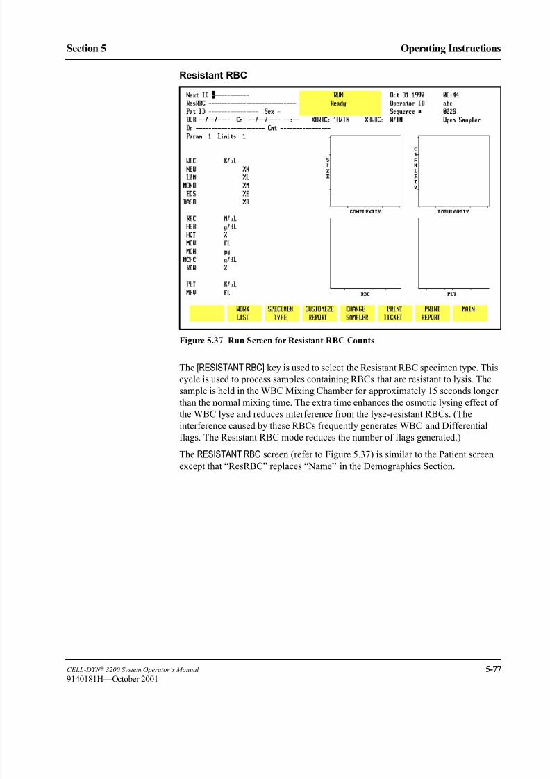
8/21/2019 Equ22-14 CellDyn3200 Op Man
http://slidepdf.com/reader/full/equ22-14-celldyn3200-op-man 235/690
CELL-DYN ® 3200 System Operator’s Manual 5-77
9140181H—October 2001
Section 5 Operating Instructions
Resistant RBC
Figure 5.37 Run Screen for Resistant RBC Counts
The [RESISTANT RBC] key is used to select the Resistant RBC specimen type. This
cycle is used to process samples containing RBCs that are resistant to lysis. The
sample is held in the WBC Mixing Chamber for approximately 15 seconds longer
than the normal mixing time. The extra time enhances the osmotic lysing effect of
the WBC lyse and reduces interference from the lyse-resistant RBCs. (The
interference caused by these RBCs frequently generates WBC and Differential
flags. The Resistant RBC mode reduces the number of flags generated.)
The RESISTANT RBC screen (refer to Figure 5.37) is similar to the Patient screen
except that “ResRBC” replaces “Name” in the Demographics Section.

8/21/2019 Equ22-14 CellDyn3200 Op Man
http://slidepdf.com/reader/full/equ22-14-celldyn3200-op-man 236/690
5-78 CELL-DYN ® 3200 System Operator’s Manual
9140181H—October 2001
Operating Instructions
Run Menu Section 5
Customize Report
The [CUSTOMIZE REPORT] key is discussed in the Set Up Instructions earlier in
this section.
Change Sampler
The [CHANGE SAMPLER] key is used to select the Open or Closed Mode of
operation. When the key is pressed, the mode changes from the mode currently
selected to the other operating mode. The Status Box displays one of the two
following messages:
SELECTING OPEN MODE
SELECTING CLOSED MODE
Prior to running a sample, if the [CHANGE SAMPLER] key is pressed, it will
automatically clear any patient information entered in the demographics section of
the RUN screen.
Print TicketThe [PRINT TICKET] key is used to print a report on a ticket when a printer is
connected to the Ticket Printer Port on the Data Module. The report is printed on
the type of ticket that is selected from the CUSTOMIZE PRINTED REPORT screen.
Print Report
The [PRINT REPORT] key is used to print a graphics report when printer is
connected to the Graphics Printer Port on the Data Module. When the color
printing option on the CUSTOMIZE PRINTED REPORT screen is ON, the key label
changes to [COLOR PRINT]. A color graphics report is printed when the [COLOR
PRINT] key is pressed and the printer connected to the Graphics Printer Port is a
color printer.
Main
The [MAIN] key is used to return to the MAIN MENU screen.

8/21/2019 Equ22-14 CellDyn3200 Op Man
http://slidepdf.com/reader/full/equ22-14-celldyn3200-op-man 237/690
CELL-DYN ® 3200 System Operator’s Manual 5-79
9140181H—October 2001
Section 5 Operating Instructions
Additional Examples of Run Menu Screens
Flagging Messages
An example of some flagging messages is shown in Figure 5.38.
A detailed explanation of all flagging messages is given in Section 3: Principles
of Operation.
Figure 5.38 Display Specimen Screen Showing Flagging Messages and RBCMORPH Message

8/21/2019 Equ22-14 CellDyn3200 Op Man
http://slidepdf.com/reader/full/equ22-14-celldyn3200-op-man 238/690
5-80 CELL-DYN ® 3200 System Operator’s Manual
9140181H—October 2001
Operating Instructions
Run Menu Section 5
Bulletin Line Messages
Bulletin Line messages alert the operator to problems with the instrument or
provide instructions. An example of a Bulletin Line message reading “Ticket
printer unavailable” is shown in Figure 5.39.
Figure 5.39 Display Specimen Screen Showing Bulletin Line Message

8/21/2019 Equ22-14 CellDyn3200 Op Man
http://slidepdf.com/reader/full/equ22-14-celldyn3200-op-man 239/690
CELL-DYN ® 3200 System Operator’s Manual 5-81
9140181H—October 2001
Section 5 Operating Instructions
Laboratory Worksheet
To display the LABORATORY WORKSHEET screen, press the Page Down key on the
keyboard while the RUN menu is displayed or while the DISPLAY SPECIMEN screen
in the DATA LOG menu is displayed.
The LABORATORY WORKSHEET screen displays additional parameters as shown in
Figure 5.40. This screen is for laboratory use only.
Figure 5.40 Laboratory Worksheet Screen
8/21/2019 Equ22-14 CellDyn3200 Op Man
http://slidepdf.com/reader/full/equ22-14-celldyn3200-op-man 240/690
5-82 CELL-DYN ® 3200 System Operator’s Manual
9140181H—October 2001
Operating Instructions
Run Menu Section 5
NOTES

8/21/2019 Equ22-14 CellDyn3200 Op Man
http://slidepdf.com/reader/full/equ22-14-celldyn3200-op-man 241/690
CELL-DYN ® 3200 System Operator’s Manual 5-83
9140181M—June 2004
Section 5 Operating Instructions
Sample Collection and Handling
AnticoagulantAll performance claims given in this manual were generated from samples
collected in K 3EDTA. Studies conducted by Abbott show equivalency of results
for K 2EDTA and K 3EDTA. Samples collected in Heparin or Sodium citrate can
also be run with no adverse effect on the instrument. However, certain results can
be affected by the use of these anticoagulants. Each laboratory should develop
protocols for handling specimens collected in these anticoagulants.
Sample Stability
Any refrigerator-stored specimens should be brought to room temperature before
processing. If specimens are to be run within eight hours after collection, storageat room temperature is recommended. If specimens are to be run more than eight
hours after collection, storage at temperatures between 2° and 8° C is
recommended.
Stability studies show that, when specimens are refrigerated at temperatures
between 2° and 8° C, and brought to room temperature before mixing and
processing, results for the RBC, HGB, MCV, PLT are stable (±5%) for up to 36
hours after collection. The total WBC and MPV is stable (±5%) for up to 24 hours
after collection. The stability of the total WBC decreases to ±10% at 36 hours after
collection. An increase in false-positive Suspect Population Flags may be seen on
samples processed less than 30 minutes or more than 4 hours after collection time.
The stability of capillary samples collected in microtainers may vary depending onthe microtainer manufacturer. Refer to the manufacturer’s package insert for
stability claims.
Sample Collection
All samples should be collected using proper technique and following the tube
manufacturer’s recommendations.
NOTE: For additional information on collecting venous and capillary samples,
refer to NCCLS Standards, H3-A31 and H4-A32.
WARNING: Potential Biohazard. Consider all specimens, reagents,
controls, calibrators, etc., that contain human blood or serum as potentiallyinfectious. Wear gloves, lab coats, and safety glasses, and follow other
biosafety practices as specified in the OSHA Bloodborne Pathogen Rule
(29 CFR Part 1910.1030) or other equivalent biosafety procedures.
Samples that will be run on the Sample Loader must have a minimum volume of
1.5 mL to ensure proper mixing by the Sample Loader.

8/21/2019 Equ22-14 CellDyn3200 Op Man
http://slidepdf.com/reader/full/equ22-14-celldyn3200-op-man 242/690
5-84 CELL-DYN ® 3200 System Operator’s Manual
9140181M—June 2004
Operating Instructions
Sample Collection and Handling Section 5
Samples that will be run on the Closed Sampler model must have a minimum
volume of 1.5 mL to ensure proper sampling.
A minimum of 180 µL should be collected for capillary samples. This ensures an
adequate amount of blood for the Open Mode (150 µL) aspiration.
Interfering Substances
It is important to note that there are commonly occurring interfering substances that
can affect the results reported by hematology analyzers. While the
CELL-DYN 3200 has been designed to detect and flag many of these substances,
it may not always be possible to do so. The following indicates some of the
substances that may interfere with each of the listed parameters.
WBC: Fragile WBCs, neutrophil aggregates, lytic-resistant RBCs, NRBCs, PLT
clumps, cryofibrinogen, cryoglobulin, paraproteins
RBC: Elevated WBC count, increased numbers of giant PLTs, auto-
agglutination, in vitro hemolysis
HGB: Elevated WBC count, increased plasma substances (triglycerides,
bilirubin, in vivo hemolysis), lytic-resistant RBCs
MCV: Elevated WBC count, hyperglycemia, in vitro hemolysis, increased
numbers of giant PLTs
PLT: WBC fragments, in vitro hemolysis, microcytic RBCs, cryofibrinogen,
cryoglobulins, PLT clumping, increased numbers of giant PLTs.
For additional information on interfering substances, refer to the table provided in
Appenidx C.
For a detailed description of the flags that are generated, refer to Section 3:
Principles of Operation; Subsection: Operational Messages and Data Flagging .
8/21/2019 Equ22-14 CellDyn3200 Op Man
http://slidepdf.com/reader/full/equ22-14-celldyn3200-op-man 243/690
CELL-DYN ® 3200 System Operator’s Manual 5-85
9140181H—October 2001
Section 5 Operating Instructions
Preparing to Run Samples
Before running specimens, the operator should enter data in the demographicssection of the RUN screen to properly identify patient samples.
Operator ID
The operator should enter an Operator ID before running samples. The Operator ID
is displayed on all screens and printed on the graphics report and the blank ticket
report. It is also retained in the QC logs and the Data Log.
The operator ID may be entered from the MAIN MENU or the CALIBRATION menu.
When either menu is selected, the cursor is positioned in the OPERATOR ID entry
field. Type up to three alphanumeric characters and press the Enter key on the
keyboard to save the ID number.
Sample Identification
Sample identification information is entered in the upper left corner of the RUN
screen. These entry fields are made available when the Patient, Fragile WBC, or
Resistant RBC specimen types are selected. To select one of these three specimen
types, do the following:
1. Go to the RUN menu and press [SPECIMEN TYPE].
2. Press one of the following keys to select the desired specimen type —
[PATIENT], [FRAGILE WBC], [RESISTANT RBC].
Enter the sample identification information as follows:
1. A Sample ID number (Next ID field) of up to 12 characters may be entered
in the NEXT ID entry field.
2. The remaining patient demographic information may be entered at the
operator’s discretion. Refer to Run Screen for Patient Samples earlier in this
section for a discussion of these fields.
3. Parameter Set 1 and Patient Limits Set 1 are the default settings when the
instrument is shipped from the factory. The results are displayed and printed
using these settings unless the operator changes these entry fields. New
parameter and/or limits sets can be entered anytime before a sample is run or
after the results of a sample run are displayed by moving the cursor to the
appropriate field and typing the desired number.
NOTE: When the results are stored in the Data Log, other parameter and
limits sets may be selected by using the [EDIT SPECIMEN] key. For
complete instructions, refer to Using the Data Log later in this
section.
8/21/2019 Equ22-14 CellDyn3200 Op Man
http://slidepdf.com/reader/full/equ22-14-celldyn3200-op-man 244/690
5-86 CELL-DYN ® 3200 System Operator’s Manual
9140181M—June 2004
Operating Instructions
Preparing to Run Samples Section 5
Sample Mixing
Proper mixing of specimens prior to sample aspiration is essential for obtaining
accurate results on the CELL-DYN 3200 System. For control or calibrator mixing
instructions, refer to the manufacturer’s product insert.
Specimens stored at refrigerator temperatures must be brought to room temperature
prior to mixing.
Specimens to be run in the Closed Mode (CS Model) or Open Mode must be well
mixed on a mechanical mixer or hand mixed by inversion per your laboratory’s
protocol. Immediately prior to sample aspiration, mix again by inverting the tube a
minimum of 10 times.
For specimens collected in micro-collection devices, refer to the manufacturer’s
insert for proper mixing and handling.
WARNING: Potential Biohazard. Consider all specimens, reagents,
controls, calibrators, etc., that contain human blood or serum as potentially
infectious. Wear gloves, lab coats, and safety glasses, and follow other
biosafety practices as specified in the OSHA Bloodborne Pathogen Rule(29 CFR Part 1910.1030) or other equivalent biosafety procedures.

8/21/2019 Equ22-14 CellDyn3200 Op Man
http://slidepdf.com/reader/full/equ22-14-celldyn3200-op-man 245/690
CELL-DYN ® 3200 System Operator’s Manual 5-87
9140181K—July 2002
Section 5 Operating Instructions
Sample Analysis on the CELL-DYN 3200SL
IntroductionThis section explains how samples are run on the CELL-DYN 3200SL model in
both Open and Closed Modes. Samples should not be run until daily QC checks
have been performed and the instrument is in the READY state. For convenience,
directions for Daily Start Up and QC are given in each section. Directions for
running samples in the Open Mode are also included in each section. Samples may
be analyzed whenever the READY message is displayed in the Status Box on the
RUN screen.
For Open Mode only, when specimens have not been run for one hour or more, a
background should be run immediately prior to running a patient specimen.
Samples should be well mixed (a mechanical mixer is preferred3) before they arerun in the Open Mode on the instrument. For specimens collected in micro-
collection devices, refer to the manufacturer’s instructions for proper mixing and
handling instructions.
The Sample Loader automatically mixes the samples immediately before aspiration.
Instrument Preparation
1. Be sure that the green READY light on the Analyzer Status Indicator Panel
is illuminated and the READY message is displayed in the Status Box on the
RUN screen.
2. If the Status Box on the Data Station RUN screen displays STANDBY orINITIALIZED press [RUN] to initiate the automatic Start Up cycle.
3. When the automatic Start Up cycle is completed, a background count is
automatically performed and the Open Mode is selected.
4. Verify that the background counts are acceptable. If the background counts
are unacceptable, repeat the background cycle. If the counts are still
unacceptable, troubleshoot accordingly.
NOTE: Backgrounds may be repeated by pressing the Touch Plate.
5. If the Sample Loader is to be used, be sure that at least one rack (maximum
of five) is in the load area to the right of the Tower Cover and that the Tower
Cover is in place.
6. To switch from Open Mode to Closed Mode, press the [CHANGE SAMPLER] key. Wait until the message READY is displayed in the Status Box.
7. Perform the daily Quality Control checks as directed in Subsection: Sample
Analysis on the CELL-DYN 3200SL.

8/21/2019 Equ22-14 CellDyn3200 Op Man
http://slidepdf.com/reader/full/equ22-14-celldyn3200-op-man 246/690
5-88 CELL-DYN ® 3200 System Operator’s Manual
9140181H—October 2001
Operating Instructions
Sample Analysis on the CELL-DYN 3200SL Section 5
Sample Loader Operating Tips
1. All Sample Loader tubing must be connected before turning ON the System.
2. All samples must be properly mixed before they are placed in the Sample
Loader racks.
3. Place the labeled tubes in the Sample Loader rack and load the rack on the
Sample Loader.
4. If a tube has multiple labels on it, spin the tube by hand after it is put in a rack
to be sure it will spin freely and therefore mix properly. (Refer to Section 13:
Sample Loader for labeling requirements.)
Daily Quality Control Checks
Quality Control checks (which confirm calibration) should be performed on a daily
basis according to the laboratory’s protocol. Commercial control materials should
be properly warmed and mixed according to the manufacturer’s recommendations.
Patient controls should be handled according to the laboratory’s protocol.
WARNING: Potential Biohazard. Consider all specimens and reagents,controls, calibrators, etc., that contain human blood or serum as potentially
infectious. Wear gloves, lab coats, and safety glasses, and follow other
biosafety practices as specified in the OSHA Bloodborne Pathogen Rule
(29 CFR Part 1910.1030) or other equivalent biosafety procedures.
Open Mode QC Procedure
1. In the RUN screen, press [SPECIMEN TYPE].
2. Move the cursor to the desired QC file and press [QC SPECIMEN].
3. If necessary, press [CHANGE SAMPLER] to select the Open Mode.
4. Run the control.
NOTE: Refer to the Running Samples subsection following this procedure
for complete instructions on running samples.
5. Verify that the results are acceptable.
NOTE: Out-of-range results are displayed in color.
6. If the results are unacceptable, repeat the run. If the results are still
unacceptable, obtain a new bottle of the control, be sure that it is warmed and
mixed properly and again repeat the run. If the results are still unacceptable,
run the other levels of control material. If the results on all levels are
unacceptable, troubleshoot as directed in Section 10: Troubleshooting and
Diagnostics; Subsection: Troubleshooting Guide.
7. When the control results are acceptable, patient samples may be analyzed.

8/21/2019 Equ22-14 CellDyn3200 Op Man
http://slidepdf.com/reader/full/equ22-14-celldyn3200-op-man 247/690
CELL-DYN ® 3200 System Operator’s Manual 5-89
9140181H—October 2001
Section 5 Operating Instructions
Closed Mode QC Procedure
The operator must manually stop the Sample Loader as directed in this procedure
when different levels of controls are run.
1. From the RUN screen, press [SPECIMEN TYPE].
2. Use the Arrow keys on the keyboard to move the cursor to the appropriate QCfile and press [QC SPECIMEN].
3. If necessary, press [CHANGE SAMPLER] to select Closed Mode.
4. Place the controls in the Sample Loader rack in the order in which they are to
be run.
5. Be sure the Tower Cover is in place and press the [START LOADER] key.
6. After the first control is aspirated, press the [STOP LOADER] key.
7. After the results are displayed, press [SPECIMEN TYPE].
8. Use the Arrow keys on the keyboard to move the cursor to the file for the next
control to be run and press [QC SPECIMEN].
9. Press the [START LOADER] key.10. Repeat steps 6 – 9 until all levels of controls have been run.
11. When all of the controls have been run, press [MAIN] followed by [QUALITYCONTROL].
12. Use the Arrow keys on the keyboard to move the cursor to the desired file.
13. Press [VIEW QC LOG] to display the QC LOG screen.
14. Verify that the results are acceptable.
NOTE: Out-of-range results are displayed in color.
15. Press [RETURN] to return to the main QUALITY CONTROL screen.
16. Repeat steps 12–15 for all levels of controls that were run.
17. If the results are unacceptable, repeat the run. If the results are stillunacceptable, obtain a new tube of control, be sure that it is warmed and
mixed properly and again repeat the run. If the results are still unacceptable, run
the other levels of control material. If the results on all levels are
unacceptable, troubleshoot as directed in Section 10: Troubleshooting and
Diagnostics; Subsection: Troubleshooting Guide.
18. When the control results are acceptable, patient samples may be analyzed.
Running Samples
WARNING: Potential Biohazard. Consider all specimens and reagents,
controls, calibrators, etc., that contain human blood or serum as potentially
infectious. Wear gloves, lab coats, and safety glasses, and follow other
biosafety practices as specified in the OSHA Bloodborne Pathogen Rule
(29 CFR Part 1910.1030) or other equivalent biosafety procedures.

8/21/2019 Equ22-14 CellDyn3200 Op Man
http://slidepdf.com/reader/full/equ22-14-celldyn3200-op-man 248/690
5-90 CELL-DYN ® 3200 System Operator’s Manual
9140181H—October 2001
Operating Instructions
Sample Analysis on the CELL-DYN 3200SL Section 5
Open Mode Analysis
The Open Sampler mode aspirates the sample from an open collection tube.OPEN
SAMPLER is displayed in the upper right corner of the RUN screen when this mode
is selected. The open sample aspiration probe is available (Wash Block raised) only
when this mode is selected.
Open Mode Procedure
1. If necessary, from the RUN screen press [CHANGE SAMPLER] to select the
Open Mode.
2. Be sure that the green READY light on the Analyzer Status Indicator Panel
is illuminated and READY is displayed in the Status Box on the RUN screen.
3. With the stopper still in the tube, mix the sample well (invert the tube a
minimum of 5 times to thoroughly mix the sample).
4. Open the sample tube and place it under the Open Sample Aspiration Probe.
Raise the tube until the end of the probe is deeply immersed in the sample.
CAUTION:Do not let the probe touch the bottom of the sample tube. It
may affect aspiration and produce erroneous results.
5. Press the Touch Plate located behind the probe to start the cycle. The yellow
BUSY light on the Analyzer Status Indicator Panel is illuminated. The Status
Box on the RUN screen displays messages to indicate the various stages of
the cycle.
6. Remove the tube when the beep sounds. The message REMOVE SPECIMEN
is displayed in the Status Box. The wash block moves down the probe and
cleans it.
7. When the cycle is finished, the wash block moves up the probe, the green
READY light on the Analyzer Status Indicator Panel is illuminated, and the
results are displayed on the RUN screen.
NOTE: Another sample may be aspirated at this point even though READY
is not displayed in the Status Box on the screen. Generally, the
READY light on the Analyzer Status Indicator Panel will be
illuminated before the Status Box on the screen displays READY.
8. If automatic report printing has been specified, a report is printed according
to the options selected during Set Up. If the Color Printing option was
selected in the CUSTOMIZED PRINTED REPORT screen for the Graphics
Printer, the printouts will be in color. Otherwise, the reports will be printed in
black and white.
9. If automatic printing has not been specified, a report may be printed by
pressing either [PRINT REPORT] or [COLOR PRINT]. The [COLOR PRINT] key
will be displayed if the Color Printing option was selected.
10. Repeat this procedure for subsequent samples.
8/21/2019 Equ22-14 CellDyn3200 Op Man
http://slidepdf.com/reader/full/equ22-14-celldyn3200-op-man 249/690
CELL-DYN ® 3200 System Operator’s Manual 5-91
9140181H—October 2001
Section 5 Operating Instructions
Closed Mode Analysis
The Closed Sampler mode on CELL-DYN 3200SL models aspirates the sample
from a closed collection tube that has been placed in a Sample Loader rack and
loaded into the Sample Loader. CLOSED SAMPLER is displayed in the upper right
corner of the RUN screen when this mode is selected. The wash block moves down
to the end of the open sample aspiration probe when this mode is selected.
Closed Mode Procedure
1. If necessary, in the RUN screen press [CHANGE SAMPLER] to select the Closed
Mode.
2. Be sure that the green READY light on the Analyzer Status Indicator Panel
is illuminated and READY is displayed in the Status Box on the RUN screen.
3. Place the well mixed samples in the Sample Loader racks.
NOTE: The racks and tube positions are identified by the bar code label on
the rack and indicated as RxTx. These numbers appear as the
Sample ID number if bar code labels are not used. (If the Work List
is used, the Sample ID number is taken from it. Refer to Using the
Work List later in this section for more information.)
4. Place the racks in the Sample Loader to the right of the Tower Cover with the
slotted side (with bar code labels) facing the operator.
5. Verify the Tower Cover is in place.
NOTE: The Sample Loader will not operate without the Tower Cover in
place.
6. Press the [START LOADER] key on the RUN screen.
7. The Sample Loader automatically processes all the samples. Processing stops
when the last rack is finished or the [STOP LOADER] key is pressed. The last
rack is finished when it has moved completely to the unload side of theSample Loader.

8/21/2019 Equ22-14 CellDyn3200 Op Man
http://slidepdf.com/reader/full/equ22-14-celldyn3200-op-man 250/690
5-92 CELL-DYN ® 3200 System Operator’s Manual
9140181H—October 2001
Operating Instructions
Sample Analysis on the CELL-DYN 3200SL Section 5
NOTES

8/21/2019 Equ22-14 CellDyn3200 Op Man
http://slidepdf.com/reader/full/equ22-14-celldyn3200-op-man 251/690
CELL-DYN ® 3200 System Operator’s Manual 5-93
9140181H—October 2001
Section 5 Operating Instructions
Sample Analysis on the CELL-DYN 3200CS
IntroductionThis section explains how samples are run on the CELL-DYN 3200CS models,
both Open and Closed Modes. Samples should not be run until daily QC checks
have been performed and the instrument is in the READY state. For convenience,
directions for Daily Start Up and QC are given in each section. Directions for
running samples in the Open Mode are also included in each section.
Samples may be analyzed whenever the READY message is displayed in the Status
Box on the RUN screen. Samples should be well mixed (a mechanical mixer is
preferred3) before they are run in the Open or Closed Mode on the instrument.
Instrument Preparation1. Be sure that the green READY light on the Analyzer Status Indicator Panel
is illuminated.
2. If the Status Box on the RUN screen displays STANDBY orINITIALIZED,
press [RUN] to initiate the automatic Start Up cycle.
3. When the cycle is finished, a background count is automatically performed
and the Open Mode is selected.
4. Verify that the background counts are acceptable. If the background counts
are unacceptable, repeat the background cycle. If the counts are still
unacceptable, troubleshoot accordingly.
NOTE: Backgrounds may be repeated by pressing the touch plate.
5. If controls will be processed in Closed Mode, press [CHANGE SAMPLER].
6. Perform the daily Quality Control checks as directed in the following section.
Daily Quality Control Checks
Quality Control checks (which confirm calibration) should be performed on a daily
basis according to the laboratory’s protocol. Commercial control materials should
be properly warmed and mixed according to the manufacturer’s recommendations.
Patient controls should be handled according to the laboratory’s protocol.
WARNING: Potential Biohazard. Consider all specimens and reagents,
controls, calibrators, etc., that contain human blood or serum as potentiallyinfectious. Wear gloves, lab coats, and safety glasses, and follow other
biosafety practices as specified in the OSHA Bloodborne Pathogen Rule
(29 CFR Part 1910.1030) or other equivalent biosafety procedures.

8/21/2019 Equ22-14 CellDyn3200 Op Man
http://slidepdf.com/reader/full/equ22-14-celldyn3200-op-man 252/690
5-94 CELL-DYN ® 3200 System Operator’s Manual
9140181H—October 2001
Operating Instructions
Sample Analysis on the CELL-DYN 3200CS Section 5
QC (Open or Closed Mode) Procedure
1. In the RUN screen, press [SPECIMEN TYPE].
2. Move the cursor to the desired QC file and press [QC SPECIMEN].
3. If necessary, press [CHANGE SAMPLER] to select the desired mode.
4. Run the control.NOTE: Refer to the Running Samples subsection following this procedure
for complete instructions on running samples.
5. Verify that the results are acceptable.
NOTE: Out-of-range results are displayed in color.
6. If the results are unacceptable, repeat the run. If the results are still
unacceptable, obtain a new bottle of the control, be sure that it is warmed and
mixed properly and again repeat the run. If the results are still unacceptable,
run the other levels of control material. If the results on all levels are
unacceptable, troubleshoot as directed in Section 10: Troubleshooting and
Diagnostics; Subsection: Troubleshooting Guide.
7. When the control results are acceptable, patient samples may be analyzed.
Running Samples
WARNING: Potential Biohazard. Consider all specimens and reagents,
controls, calibrators, etc., that contain human blood or serum as potentially
infectious. Wear gloves, lab coats, and safety glasses, and follow other
biosafety practices as specified in the OSHA Bloodborne Pathogen Rule
(29 CFR Part 1910.1030) or other equivalent biosafety procedures.
Open Mode Analysis
The Open Sampler mode aspirates the sample from an open collection tube.OPENSAMPLER is displayed in the upper right corner of the RUN screen when this mode
is selected. The Open Sample Aspiration Probe is available only when this mode is
selected.
Open Mode Procedure
1. If necessary, in the RUN screen press [CHANGE SAMPLER] to select the Open
Mode.
2. Be sure that the green READY light on the Analyzer Status Indicator Panel
is illuminated and READY is displayed in the Status Box on the RUN screen.
3. With the stopper still in the tube, mix the sample well (invert the tube a
minimum of 5 times to thoroughly mix the sample).4. Open the sample tube and place it under the Open Sample Aspiration Probe.
Raise the tube until the end of the probe is deeply immersed in the sample.
NOTE: Do not let the probe touch the bottom of the sample tube. It may
affect aspiration and produce erroneous results.

8/21/2019 Equ22-14 CellDyn3200 Op Man
http://slidepdf.com/reader/full/equ22-14-celldyn3200-op-man 253/690
CELL-DYN ® 3200 System Operator’s Manual 5-95
9140181H—October 2001
Section 5 Operating Instructions
5. Press the Touch Plate located behind the probe to start the cycle. The yellow
BUSY light on the Analyzer Status Indicator Panel is illuminated. The Status
Box on the RUN screen displays messages to indicate the various stages of the
cycle.
6. Remove the tube when the beep sounds. The messageREMOVE SPECIMEN
is displayed in the Status Box. The wash block moves down the probe andcleans it.
7. When the cycle is finished, the wash block moves up the probe, the green
READY light on the Analyzer Status Indicator Panel is illuminated, and the
results are displayed on the RUN screen.
NOTE: Another sample may be aspirated at this point even though READY
is not displayed in the Status Box on the screen. Generally, the
READY light on the Analyzer Status Indicator Panel will be
illuminated before the Status Box on the screen displays READY.
8. If automatic report printing has been specified, a report is printed according
to the options selected during Set Up. The reports are printed in black and
white. If automatic printing has not been specified, a report may be printed by pressing [PRINT REPORT].
NOTE: To obtain a color printout, press [COLOR PRINT]. (The color printing
option on the CUSTOMIZE PRINTED REPORT screen must be ON.)
9. Repeat this procedure for subsequent samples.
Closed Mode Analysis
The Closed Sampler mode on Closed Sampler (CS) instruments aspirates the
sample from a closed collection tube that has been inserted in the Closed Sample
Tower Module. CLOSED SAMPLER is displayed in the upper right corner of the
RUN screen when this mode is selected. The wash block moves down to the end
of the Open Sample Aspiration Probe when this mode is selected.

8/21/2019 Equ22-14 CellDyn3200 Op Man
http://slidepdf.com/reader/full/equ22-14-celldyn3200-op-man 254/690
5-96 CELL-DYN ® 3200 System Operator’s Manual
9140181H—October 2001
Operating Instructions
Sample Analysis on the CELL-DYN 3200CS Section 5
Closed Mode Procedure
1. Be sure that the green READY light on the Analyzer Status Indicator Panel
is illuminated and READY is displayed in the Status Box on the RUN screen.
2. If necessary, in the RUN screen press [CHANGE SAMPLER] to select the
Closed Mode.
3. With the stopper still in the tube, mix the sample well (invert the tube a
minimum of 5 times to thoroughly mix the sample).
4. Place the well-mixed sample, with the stopper facing up, into the Tube
Holder and push the door closed.
NOTE: The Touch Plate will not operate if the door has not been closed.
5. Press the Touch Plate located behind the probe to start the cycle. The yellow
BUSY light on the Analyzer Status Indicator Panel is illuminated.
6. Remove the tube when the door opens. A beep sounds when the door opens.
NOTE: The door automatically opens whenever a sample has been
aspirated in the Closed Mode or a background count has been run
in Open Mode. There is also a tab under the Door Assembly thatmechanically releases the door. This tab can be used if the door is
closed and no tube is in the holder. The door will not open if the
needle is in the tube. In case of an emergency stop, the operator will
have to remove the Tower Cover and manually raise the needle out
of the sample.
7. When the cycle is finished, the green READY light on the Analyzer Status
Indicator Panel is illuminated and the results are displayed on the RUN screen.
NOTE: Another sample may be aspirated at this point even though READY
is not displayed in the Status Box on the screen. Generally, the
READY light on the Analyzer Status Indicator Panel will be
illuminated before the Status Box on the screen displays READY.
8. Repeat this procedure for subsequent samples.
8/21/2019 Equ22-14 CellDyn3200 Op Man
http://slidepdf.com/reader/full/equ22-14-celldyn3200-op-man 255/690
CELL-DYN ® 3200 System Operator’s Manual 5-97
9140181H—October 2001
Section 5 Operating Instructions
Alerts and Indicators
This subsection describes information displayed on the screen as the samples areanalyzed and/or when reports are printed. This subsection does not discuss how to
interpret parameter flags, which are displayed after the sample is run. Refer to
Section 3: Principles of Operation; Subsection: Operational Messages and Data
Flagging .
Out of Range
• Results that fall outside the range of the selected limit set are displayed in
color. Yellow indicates that the result exceeded the lower limit and purple
indicates that the result exceeded the upper limit. These results are underlined
on the graphics and blank ticket printouts. They are indicated by an asterisk
on a pre-printed ticket.
• Results that exceed a parameter’s linear range are indicated by >>>> in place
of the result.
Fault Conditions
The [CLEAR FAULT] key is displayed and a message (e.g., DILUENT EMPTY)
appears in the Status Box if a fault condition is detected. The word “Fault” on the
Analyzer status indicator is illuminated in red. The Status Box displays the message
FAULT: SEE DIAG orSEE SPECIAL to direct the operator to the DIAGNOSTICS or
SPECIAL PROTOCOLS menu for further instructions.
After the problem has been corrected, press [CLEAR FAULT] to resume operation.
Flow Errors
If a RBC Flow Error occurs, results are suppressed for the RBC/PLT parameters
and the RBC FLOW ERROR message is displayed on the Bulletin line. The RBC/
PLT scatterplots are suppressed.
If a WOC Flow Error occurs, results are suppressed for the WBC and Differential
and the WOC FLOW ERROR message is displayed on the Bulletin line. The WBC
scatterplots are suppressed.
If a NOC Flow Error occurs, results are suppressed for the WBC and Differential
and the NOC FLOW ERROR message is displayed on the Bulletin line. The NOCscatterplots are suppressed.

8/21/2019 Equ22-14 CellDyn3200 Op Man
http://slidepdf.com/reader/full/equ22-14-celldyn3200-op-man 256/690
5-98 CELL-DYN ® 3200 System Operator’s Manual
9140181H—October 2001
Operating Instructions
Alerts and Indicators Section 5
3 Consecutive Flow Errors
If the Sample Loader is being used and the instrument detects one of the following:
1. Three consecutive RBC flow errors.
2. Three consecutive WOC flow errors.
3. Three consecutive NOC flow errors.The Sample Loader halts at the end of the cycle and the Bulletin line displays the
appropriate message:
1. 3 CONSECUTIVE RBC FLOW ERRORS.
2. 3 CONSECUTIVE WOC FLOW ERRORS.
3. 3 CONSECUTIVE NOC FLOW ERRORS.
Sampling Errors
The message SAMPLING ERROR-INCOMPLETE ASPIRATION is displayed on
the Bulletin line if insufficient sample was detected during aspiration. SAMPLING
ERR is displayed on the screen and SAMPLING ERR is printed on the graphicsreport to the right of the MCHC. The same message is printed to the right of the
WBC on the pre-printed ticket and printed above the list of parameters on the blank
ticket.
3 Consecutive Sampling Errors
If the Sample Loader is being used and the Instrument detects three consecutive
incomplete aspirations, the Sample Loader halts at the end of the cycle and the
Bulletin line displays the message
3 CONSECUTIVE INCOMPLETE ASPIRATIONS.

8/21/2019 Equ22-14 CellDyn3200 Op Man
http://slidepdf.com/reader/full/equ22-14-celldyn3200-op-man 257/690
CELL-DYN ® 3200 System Operator’s Manual 5-99
9140181K—July 2002
Section 5 Operating Instructions
Daily Shutdown Procedure
Daily ShutdownThe Daily Shutdown Procedure consists of rinsing the Flow System. Whether or
not this procedure is followed on a daily basis depends on instrument usage and the
laboratory’s procedures. It may not be necessary to perform this procedure every
day, since the instrument automatically goes into a STANDBY state (Automatic
Shutdown) if it has been idle for four hours. Before the instrument enters the
STANDBY state, the Flow Panel is automatically rinsed.
If desired, the operator may place the instrument in the STANDBY state by
pressing the [DAILY SHUTDOWN] soft key in the second level SPECIAL PROTOCOLS
menu. When this key is pressed or when Automatic Shutdown is initiated, the
following occurs:
• The Flow System is rinsed.
• The timer control, which periodically opens all of the solenoid valves to
prevent pinched tubing, is set.
The Daily Shutdown cycle takes approximately 10 minutes.
For a more thorough cleaning of the instrument prior to Daily Shutdown, perform
the following procedures:
1. In the SPECIAL PROTOCOLS menu, press [AUTO CLEAN].
2. Clean Sample Loader including racks and Tower Cover.
3. Press [DAILY SHUTDOWN].
4. Leave Power ON.
5. Empty Waste (as needed)
NOTE: The Auto-Clean cycle may be run as part of the Daily Start-Up
Procedure, depending on operator preference. The Clean Needle
process should be used if there is a problem with Closed Mode
aspiration and an obstruction in the needle is a suspected cause.
The Auto-Clean and Clean Needle procedures are described in detail in Section 9:
Service and Maintenance; Subsection: Daily Maintenance Procedures.
Procedures for cleaning the Sample Loader are described in detail in Section 13:
Sample Loader .
In addition to the daily procedures listed above, if the instrument will remain idle
for a period of time, then supplemental shutdown procedures are required
depending on the expected duration of the idle time — Short-term, Intermediate,
or Prolonged Shutdown. These categories are discussed below.

8/21/2019 Equ22-14 CellDyn3200 Op Man
http://slidepdf.com/reader/full/equ22-14-celldyn3200-op-man 258/690
5-100 CELL-DYN ® 3200 System Operator’s Manual
9140181H—October 2001
Operating Instructions
Daily Shutdown Procedure Section 5
Peristaltic Pump Tubing
IMPORTANT: By removing the tubing under the Sample Transfer Peristaltic
Pump, the life of the tubing is significantly prolonged. The tubing should be
removed if the instrument will be idle for more than 24 hours and reinserted prior
to operating the instrument.
Short Term Shutdown
If the shutdown time is expected to be 72 hours or less, follow the procedure below:
1. In the MAIN MENU, press [SPECIAL PROTOCOLS].
2. If the instrument is to be cleaned first, press [AUTO CLEAN], otherwise go to
step 3.
3. Press [DAILY SHUTDOWN].
4. Leave power ON.
5. Tubing should be removed from under the Peristaltic Pump.
Intermediate-term ShutdownIf the shutdown time is expected to exceed 72 hours (but less than 2 weeks), follow
the procedure below:
1. With the system still ON, perform any maintenance that is due.
2. In the MAIN MENU, press [SPECIAL PROTOCOLS].
3. Press [AUTO CLEAN] to clean the instrument.
4. Press [DAILY SHUTDOWN].
5. When the DAILY SHUTDOWN cycle is finished, turn power OFF in the
following order:
a. System (includes Analyzer, Data Module, and Sample Loader)
b. Display Monitor
c. Printer
NOTE: In an emergency situation, turn OFF power in any order as quickly
as possible.
6. Remove the tubing from under the Sample Transfer Peristaltic Pump.
8/21/2019 Equ22-14 CellDyn3200 Op Man
http://slidepdf.com/reader/full/equ22-14-celldyn3200-op-man 259/690
CELL-DYN ® 3200 System Operator’s Manual 5-101
9140181H—October 2001
Section 5 Operating Instructions
Prolonged Shutdown
If the shutdown time is expected to exceed two weeks, follow the procedure below:
1. In the MAIN MENU, press [SPECIAL PROTOCOLS].
2. Press [AUTO CLEAN] to clean the instrument.
3. Press [PREPARE FOR SHIPPING]. Follow the instructions on the screen.4. When the procedure is completed, turn the power OFF.
5. Remove the following tubing:
• Tubing in the Normally Closed Valves on the Flow Panel (refer to Figure
1.5).
• Tubing under the Peristaltic Pump.
6. Record this maintenance in your maintenance log.
CAUTION: Do not forget to reinsert the tubing securely in the Normally
Closed Valves and under the peristaltic pump before turning the instrument
back ON. Refer to Section 2: Installation Procedures and Special
Requirements; Subsection: Tubing Installation.
For the SL model, also refer to the Prolonged Shutdown Procedure in Section 13:
Sample Loader .
If the instrument will be shipped, refer to the instructions in Section 9: Service and
Maintenance; Subsection: Preparation for Shipping or Extended Period of Non-
Use.

8/21/2019 Equ22-14 CellDyn3200 Op Man
http://slidepdf.com/reader/full/equ22-14-celldyn3200-op-man 260/690
5-102 CELL-DYN ® 3200 System Operator’s Manual
9140181H—October 2001
Operating Instructions
Daily Shutdown Procedure Section 5
NOTES
8/21/2019 Equ22-14 CellDyn3200 Op Man
http://slidepdf.com/reader/full/equ22-14-celldyn3200-op-man 261/690
CELL-DYN ® 3200 System Operator’s Manual 5-103
9140181H—October 2001
Section 5 Operating Instructions
Using The Work List
IntroductionThe Work List is used to pre-assign sample identification and display and print
criteria for samples that will be run. It is essentially a list of samples (including the
pre-assigned information) that the operator intends to run on the instrument. Work List
entries may be downloaded from a host computer to the CELL-DYN 3200 System,
or the entries can be made by an operator at the instrument.
This section will provide an overall review of the Work List, discuss the WORK LIST
menu and WORK LIST SET UP menu, and discuss the procedures for running
samples under the following conditions:
1. Work List records with Bar Codes in the <Specimen ID> field are
downloaded from the LIS.2. Work List records with other sample identification (non Bar Code) in the
<Specimen ID> field are downloaded from the LIS.
3. Work List records with Bar Codes in the <Specimen ID> field are entered at
the instrument by the operator.
4. Work List records with other sample identification (non Bar Code) in the
<Specimen ID> field are entered at the instrument by the operator.
As samples are processed, the Work List is accessed. If the identifying information
on the sample, such as a bar code number, matches the identifying information of
an entry in the Work List, then a “match” has occurred and that entry is removed
from the Work List. The demographic data and the results of the sample run are
displayed on the RUN screen and stored in the Data Log. The demographic data isalso included on the printed report.
The Work List can accept a specimen identifier other than a bar code in the
Specimen ID field. However, since both models come equipped with a bar code
reader for the Closed Mode, it is expected that bar code numbers will be the
preferred method for identifying samples.
The following bar code symbologies may be used in the <Specimen ID> field:
• Code 39, Code 128, Interleaved 2 of 5, and Codabar
NOTE: Refer to Appendix A for complete information on the use of bar
code labels.
NOTE: The number on bar code labels must be greater than 2 digits to
avoid possible confusion by the bar code reader with the 2 digit bar
code label on the racks.
8/21/2019 Equ22-14 CellDyn3200 Op Man
http://slidepdf.com/reader/full/equ22-14-celldyn3200-op-man 262/690
5-104 CELL-DYN ® 3200 System Operator’s Manual
9140181H—October 2001
Operating Instructions
Using The Work List Section 5
Quick Guide
The Work List has been designed with three objectives in mind:
1. Relieve the operator from the task of entering demographic data by
downloading that data from a host.
2. Process samples quickly, efficiently, and accurately.3. Upload sample results with corresponding demographic data to the LIS for
distribution to authorized personnel.
SL Model
If the instrument is the SL model and bar codes are used with Work List entries, the
operator should do the following:
1. Wait for Work List entries to be downloaded from the host.
2. Place the samples in the racks and load the racks onto the Sample Loader.
3. In the RUN screen, press [CHANGE SAMPLER] to select the Closed Mode if
necessary.
4. Press [SPECIMEN TYPE] followed by the appropriate specimen type (Patient,
Fragile WBC, or Resistant RBC).
5. Press [START LOADER] to begin processing.
6. When processing is finished, verify that all entries have been deleted from the
Work List, indicating that all samples were successfully matched to their
corresponding entries.
CS Model
If the instrument is the CS model and bar codes are used with Work List entries, the
operator should do the following:
1. Wait for Work List entries to be downloaded from the host.2. Place a sample tube in the Door Assembly and close the door.
3. In the RUN screen, press [CHANGE SAMPLER] to select the Closed Mode if
necessary.
4. Press [SPECIMEN TYPE] followed by the appropriate specimen type (Patient,
Fragile WBC, or Resistant RBC).
5. Press the Touch Plate to begin processing.
6. When processing is finished, verify that all entries have been deleted from the
Work List, indicating that all samples were successfully matched to their
corresponding entries.

8/21/2019 Equ22-14 CellDyn3200 Op Man
http://slidepdf.com/reader/full/equ22-14-celldyn3200-op-man 263/690
CELL-DYN ® 3200 System Operator’s Manual 5-105
9140181M—June 2004
Section 5 Operating Instructions
Work List Review
General
1. The Work List is always ON.
2. A host can download Work List records at any time. The instrument will
accept any record with data in the <Specimen ID> field. This field may
contain a bar code number or other Specimen ID.
3. If a record is sent with a blank <Specimen ID> field, the instrument will
reject that record and respond by sending a message back to the host
identifying the record that was rejected and stating the reason for the
rejection.
4. The Work List can contain “mixed” records: Some records may have bar
code numbers in the <Specimen ID> field and some may have other
Specimen ID numbers.
5. The Work List can hold a maximum of 600 records. If a batch of records is
sent by the host but there is insufficient space in the Work List to accept all
the records, the instrument will not accept any of the records and responds by
sending a message back to the host stating the Work List is full.
6. When fields have been turned ON in the WORK LIST SET UP menu, those
fields are highlighted on the Work List. The cursor automatically skips to the
next highlighted field when the Enter key is pressed.
7. If the operator types in a bar code number or non-bar code Specimen ID into
the Specimen ID field on the RUN screen and presses the Return key, the
system immediately searches the Work List for a matching entry. If a match
is found, the demographic information is displayed on the RUN screen.
NOTE: This feature is not possible on the SL model Closed Mode because
the operator cannot input data to the RUN screen.
Download from HostWhen using the LIS communication feature to receive work orders from the LIS or
send records to the LIS:
DO NOT use a Specimen ID with trailing spaces in the Work List entry. Trailing
spaces will be removed and may result in entries remaining in the Work List.
DO NOT use a comma in the bar code string, if you use a Sample Loader
instrument AND Code 128-type bar codes. A comma will cause the Specimen ID
to be truncated at the point where the comma is located within the ID. This will
result in an erroneous Specimen ID or Rack and Tube Number, without any error
notification.
1. In most cases, it is expected that Work List data will be downloaded from a
host. As an alternative, the operator may enter all demographic data —
including either a Bar Code, other Specimen ID, or Rack and Tube # — at the
instrument.
2. If Work List records with Bar Codes are downloaded from the host, the
samples given to the operator for processing must also have Bar Codes,
otherwise no matches can occur.

8/21/2019 Equ22-14 CellDyn3200 Op Man
http://slidepdf.com/reader/full/equ22-14-celldyn3200-op-man 264/690
5-106 CELL-DYN ® 3200 System Operator’s Manual
9140181M—June 2004
Operating Instructions
Using The Work List Section 5
3. If Work List records with Specimen IDs (non Bar Code) are downloaded
from the host and the operator is given samples with Specimen IDs, the
operator may do the following:
a. For SL models Closed Mode: Enter the Rack and Tube # of each sample
into the <Rack and Tube> field for the appropriate Work List entry.
b. For SL models Open Mode: Enter the Specimen ID of each sample intothe <Next ID> field on the RUN screen before processing the sample.
c. For CS models Open and Closed Modes: Enter the Specimen ID of each
sample into the <Next ID> field on the RUN screen before processing the
sample.
Format
1. The Work List will be searched only when the following Specimen Types are
selected in the RUN screen: Patient, Fragile WBC, or Resistant RBC. Work
List cannot be used when Background or QC Specimen are selected.
2. There are 3 formats for matching samples with Work List entries: Bar Code,
other Specimen ID, and Rack and Tube #.
3. The <Specimen ID> field in the Work List must have either a bar code
number or other Specimen ID.
4. The <Rack and Tube #> is a separate field in the Work List record.
Matching Entries
As stated earlier, the Work List is always ON. If the Work List contains records
when samples are processed in either Closed or Open Mode, the system will:
1. Attempt to match the bar code number (if any) on the sample tube with a bar
code number in the Work List. The match must be exact, including upper/
lower case.
2. Attempt to match the Specimen ID (non Bar Code) entered on theRUN screen
with a Specimen ID (non Bar Code) in the Work List entry.
3. Attempt to match the rack and tube position of a sample with a Rack and
Tube # in the Work List (the instrument reads the bar code on the rack and
keeps track of each tube position).
If a match occurs, that entry is removed from the Work List. The results of that
sample along with its demographic data are displayed on the RUN screen and stored
in the Data Log.
If a sample cannot be matched with any of the entries in the Work List, no entries
are deleted from the Work List. The results of that sample are displayed on the RUN
screen without demographic data (except for the Bar Code, Specimen ID, orsystem-assigned Rack and Tube number) and stored in the Data Log in the same
manner. To add demographic data to that sample, the operator must go the Data
Log and, using the [EDIT SPECIMEN] soft key, enter the appropriate demographic
information.
If the instrument is unable to read a Bar Code on the tube and is unable to read the
bar code on the rack, a malfunction has occurred. Sample Loader processing is
terminated to avoid possible sample mis-identification and a fault message is
displayed.

8/21/2019 Equ22-14 CellDyn3200 Op Man
http://slidepdf.com/reader/full/equ22-14-celldyn3200-op-man 265/690
CELL-DYN ® 3200 System Operator’s Manual 5-107
9140181M—June 2004
Section 5 Operating Instructions
SL Model — Closed Mode
In the SL Closed Mode, the Work List is searched after each tube bar code is read
(the RUN cycle has begun).Work List entries are matched using one of the
following two methods:
1. Bar Codes on the sample tubes (for Bar Code Reader).
2. Rack and Tube # entered into the Work List by the operator.
NOTE: Demographic data cannot be entered into the RUN screen in the
Closed Mode on the SL model.
CS Model — Closed Mode
In the CS Closed Mode, the Work List is searched after each tube bar code is read
(the RUN cycle has begun). Work List entries are matched using one of the
following three methods:
1. Bar Codes on the sample tubes (for Bar Code Reader).
2. Bar Codes entered into the <Next ID> field of the RUN screen by the operator.
3. Non-Bar Code Specimen IDs entered into the <Next ID> field on the RUN screen by the operator.
SL Model — Open Mode
In the SL Open Mode, the Work List is searched as soon as the operator enters a
bar code number or non-bar code Specimen ID in the <Next ID> field and presses
the Enter key. If a match is found, the demographic information is immediately
displayed on the RUN screen. This will occur even if the Touch Plate is not pressed.
Work List entries are matched using one of the following two methods:
1. Bar Codes entered into the <Next ID> field of the RUN screen by the operator.
2. Non-Bar Code Specimen IDs entered into the <Next ID> field on the RUN
screen by the operator.
CS Model — Open Mode
In the CS Open Mode, the Work List is searched as soon as the operator enters a
bar code number or non-bar code Specimen ID in the <Next ID> field and presses
the Enter key. If a match is found, the demographic information is immediately
displayed on the RUN screen. This will occur even if the Touch Plate is not pressed.
Work List entries are matched using one of the following two methods:
1. Bar Codes entered into the <Next ID> field of the RUN screen by the operator.
2. Non-Bar Code Specimen IDs entered into the <Next ID> field on the RUN
screen by the operator.
Work List Menu
Work List
The [WORK LIST] key is displayed on the RUN screen. The WORK LIST screen and
the following soft key labels are displayed when the [WORK LIST] key is pressed:
INSERT/DELETE
DELETE ALL

8/21/2019 Equ22-14 CellDyn3200 Op Man
http://slidepdf.com/reader/full/equ22-14-celldyn3200-op-man 266/690
5-108 CELL-DYN ® 3200 System Operator’s Manual
9140181M—June 2004
Operating Instructions
Using The Work List Section 5
WORK LIST SET UP
PRINT WORK LIST
RETURN
Figure 5.41 Work List Screen - Page 1
Figure 5.42 Work List Screen - Page 2
8/21/2019 Equ22-14 CellDyn3200 Op Man
http://slidepdf.com/reader/full/equ22-14-celldyn3200-op-man 267/690
CELL-DYN ® 3200 System Operator’s Manual 5-109
9140181H—October 2001
Section 5 Operating Instructions
Work List Screen
The two pages of the WORK LIST screen are depicted in Figures 5.41 and 5.42. Use
the left and right arrow keys to scroll between the pages.
1. Sequence #
The sequential number of the Work List entries is displayed in this field. TheWork List holds 600 entries. When the Work List is full, existing entries must
be deleted before additional entries can be made. Work List entries are
automatically deleted as samples are run and “matches” made.
2. RACK AND TUBE #
The rack and tube number is displayed as xxyy where xx, the rack number, is
any two digit number between 01 and 99 inclusively and yy, the tube number,
is any two digit number between 01 and 10 inclusively.
NOTE: Rack and tube number can only be entered by the operator at the
instrument, not downloaded from a host.
In the Work List, the cursor skips the <Rack and Tube> field when movingfrom entry to entry. The cursor always starts in the <Specimen ID> field. To
place the cursor in the <Rack and Tube> field, the operator must use the left
arrow key to move the cursor from the <Specimen ID> field to the <Rack and
Tube> field.
3. SPECIMEN ID
The specimen identification must consist of either a Bar Code number or
other Specimen ID. Up to 12 characters may be entered. The sample is
identified on the RUN screen, in the Data Log, and on the printed report using
the information entered in this field.
NOTE: An entry must be made in this field to create a Work List record.
Also, an entry must be made in this field before a Work List recordcan be downloaded from a host.
4. PATIENT NAME
The name entered in this field should be associated with the bar code number
or rack and tube number entered in the <Specimen ID> field. Up to 28
characters can be entered in this field.
5. PATIENT ID
The Patient ID can be a social security number or other identifier. Up to 16
characters can be entered in this field.
6. PATIENT SEX
Either “M” or “F” may be entered for the sex of the patient.
7. PATIENT DOB
The patient’s date of birth may be entered in this field using the format
selected in the Date/Time Set Up menu, such as mm/dd/yyyy. Note that 4
digits are used for the year.

8/21/2019 Equ22-14 CellDyn3200 Op Man
http://slidepdf.com/reader/full/equ22-14-celldyn3200-op-man 268/690
5-110 CELL-DYN ® 3200 System Operator’s Manual
9140181H—October 2001
Operating Instructions
Using The Work List Section 5
8. COLLECTION DATE AND TIME
The date and time the specimen was collected may be entered in this field.
Date is entered as mm/dd for month and day only with no year. Time is
entered as hh/mm where hh represents the hour (from 00 to 23) and mm
represents the minute (from 00 to 59).
9. DR NAME
The name of the patient’s doctor may be entered in this field. Up to 22
characters may be entered.
10. LIMIT SET
This field is used to enter the number of the Patient Limit Set that will be used
for flagging the sample. If no entry is made, the default (pre-selected) Patient
Limit Set is used.
11. PARAMETER SET
This field is used to enter the number of the Parameter Set that will be used
for the sample. If no entry is made, the default (pre-selected) Parameter Set
is used.
Work List Soft Keys
The function of each of the soft keys displayed on the WORK LIST screen is
discussed below.
Insert/Delete
When the [INSERT/DELETE] key is pressed, the following soft key labels are
displayed:
INSERT
DELETERETURN
Insert
The [INSERT] key is used to insert a line of information into the Work List. The line
is inserted at the cursor position and the remainder of the Work List is moved down
one line.
Delete
The [DELETE] key is used to delete a line of information from the Work List. When
the [DELETE] key is pressed, the following soft key labels are displayed:
CONFIRM DELETIONCANCEL DELETION
These keys are used to [CONFIRM] or [CANCEL] the Delete command.
The line is deleted at the cursor position and the remainder of the Work List is
moved up one line.
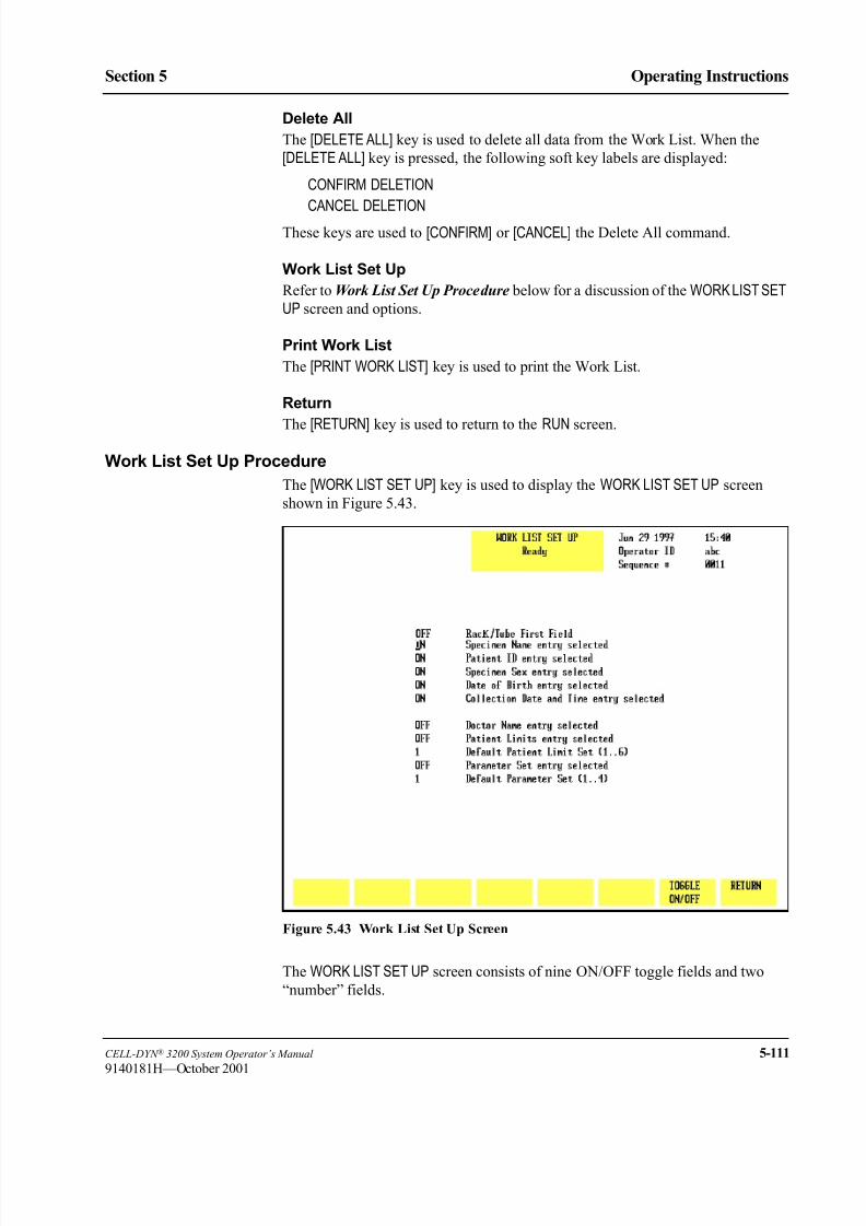
8/21/2019 Equ22-14 CellDyn3200 Op Man
http://slidepdf.com/reader/full/equ22-14-celldyn3200-op-man 269/690
CELL-DYN ® 3200 System Operator’s Manual 5-111
9140181H—October 2001
Section 5 Operating Instructions
Delete All
The [DELETE ALL] key is used to delete all data from the Work List. When the
[DELETE ALL] key is pressed, the following soft key labels are displayed:
CONFIRM DELETION
CANCEL DELETION
These keys are used to [CONFIRM] or [CANCEL] the Delete All command.
Work List Set Up
Refer to Work List Set Up Procedure below for a discussion of the WORK LIST SETUP screen and options.
Print Work List
The [PRINT WORK LIST] key is used to print the Work List.
Return
The [RETURN] key is used to return to the RUN screen.
Work List Set Up Procedure
The [WORK LIST SET UP] key is used to display the WORK LIST SET UP screen
shown in Figure 5.43.
Figure 5.43 Work List Set Up Screen
The WORK LIST SET UP screen consists of nine ON/OFF toggle fields and two
“number” fields.

8/21/2019 Equ22-14 CellDyn3200 Op Man
http://slidepdf.com/reader/full/equ22-14-celldyn3200-op-man 270/690
5-112 CELL-DYN ® 3200 System Operator’s Manual
9140181H—October 2001
Operating Instructions
Using The Work List Section 5
Use the arrow keys to move the cursor to the desired field. Use the [TOGGLE ON/OFF] key to change an option and advance the cursor to the next field.
ON/OFF Fields
Turning fields ON or OFF in this screen affects the movement of the cursor in the
WORK LIST screen when the operator makes entries to the Work List.
1. When the operator enters data into a <Work List> field and presses the Enter
key, the cursor will move to the next field that was turned ON in the WORKLIST SET UP screen, skipping any intervening fields that were left OFF.
2. For example:
a. Only the <Dr Name> field in the WORK LIST SET UP screen was turned
ON, and
b. The operator is making new patient entries into the Work List.
In this case, when the operator enters data in the <Specimen ID> field and
presses the Enter key, the cursor goes to the next ON field, which in this
example is Dr Name. All intervening fields are skipped.
NOTE: OFF fields will still accept data. The operator can use the arrow
keys to move the cursor to an OFF field and input data. Pressing the
Enter key saves the data and moves the cursor to the next ON field.
Number Fields
The system will accept any number in the range 1 to 6 for Patient Limits and 1 to
4 for Parameter Set. The number selected for either field serves as the default for
that field for subsequent entries and is independent of whether that field is ON or
OFF.
For example:
1. If the <Patient Limits> field is OFF but the default setting is changed to 6,
then 6 will be displayed as the default setting on the Work List.
2. Because the <Patient Limits> field is OFF, the cursor will bypass this field in
the Work List.
3. If the <Patient Limits> field were ON, the cursor in the Work List would stop
in this field, allowing the operator to select a different setting, such as 2, for
that entry. The next entry would continue to display the default setting, which
in this example is 6.
NOTE: Regardless of the default value for either the <Limit Set> or
<Parameter Set> fields, the operator can use the arrow keys to
move the cursor to the field and enter another value. This new value
will affect only that entry. All previous entries will retain their
original settings, and all subsequent entries will use the default
setting selected in the WORK LIST SET UP menu.

8/21/2019 Equ22-14 CellDyn3200 Op Man
http://slidepdf.com/reader/full/equ22-14-celldyn3200-op-man 271/690
CELL-DYN ® 3200 System Operator’s Manual 5-113
9140181H—October 2001
Section 5 Operating Instructions
Work List Set Up Menu Fields
1. SPECIMEN NAME ENTRY SELECTED
This field is used to specify whether or not a specimen (patient) name will be
entered into the Work List. If this option is turned OFF, the cursor will skip
to the next ON field. However, the operator can use the arrow keys to place
the cursor in this field and enter data, if desired.
2. PATIENT ID ENTRY SELECTED
This field is used to specify whether or not a patient ID will be entered into
the Work List. If this option is turned OFF, the cursor will skip to the next ON
field. However, the operator can use the arrow keys to place the cursor in this
field and enter data, if desired.
3. PATIENT SEX ENTRY SELECTED
This field is used to specify whether or not the sex of the patient will be
entered into the Work List. If this option is turned OFF, the cursor will skip
to the next ON field. However, the operator can use the arrow keys to place
the cursor in this field and enter data, if desired.4. PATIENT DOB ENTRY SELECTED
This field is used to specify whether or not the patient’s date of birth will be
entered into the Work List. If this option is turned OFF, the cursor will skip
to the next ON field. However, the operator can use the arrow keys to place
the cursor in this field and enter data, if desired.
5. COLLECTION DATE AND TIME ENTRY SELECTED
This field is used to specify whether or not the collection date and time of the
specimen will be entered into the Work List. If this option is turned OFF, the
cursor will skip to the next ON field. However, the operator can use the arrow
keys to place the cursor in this field and enter data, if desired.
6. DR NAME ENTRY SELECTED
This field is used to specify whether or not the name of the patient’s doctor
will be entered into the Work List. If this option is turned OFF, the cursor will
skip to the next ON field. However, the operator can use the arrow keys to
place the cursor in this field and enter data, if desired.
7. PATIENT LIMITS ENTRY SELECTED
If this option is turned OFF, the prior setting will be entered automatically for
each entry. The operator can, however, input a different setting for individual
entries by using the arrow keys to place the cursor in this field and type in a
new setting. The new setting applies only to the entry(ies) that was changed.
If this option is turned ON, the operator may then select another default
setting by typing in a number from 1 to 6. This new setting will be
automatically assigned to each new entry by the operator. The operator also
has the ability to enter a different setting for individual entries. When the
cursor moves to the <Patient Limits Set> field of a particular entry, the
operator may override the default setting and type in a new setting for that
entry.

8/21/2019 Equ22-14 CellDyn3200 Op Man
http://slidepdf.com/reader/full/equ22-14-celldyn3200-op-man 272/690
5-114 CELL-DYN ® 3200 System Operator’s Manual
9140181H—October 2001
Operating Instructions
Using The Work List Section 5
8. DEFAULT PATIENT LIMIT SET (1 to 6)
This field is used to specify the default (pre-assigned) Patient Limit Set that
is automatically assigned to each sample unless otherwise indicated in the
Work List. Any number between 1 and 6 inclusively may be entered.
9. PARAMETER SET ENTRY SELECTED
If this option is turned OFF, the prior setting will be entered automatically for
each entry. The operator can, however, input a different setting for individual
entries by using the arrow keys to place the cursor in this field and type in a
new setting. The new setting applies only to the entry(ies) that was changed.
If this option is turned ON, the operator may then select another default
setting by typing in a number from 2 to 4. This new setting will be
automatically assigned to each new entry. The operator also has the ability to
enter a different setting for individual entries. When the cursor moves to the
<Parameter Set> field of a particular entry, the operator may override the
default setting and type in a new setting for that entry.
10. DEFAULT PARAMETER SET (1 to 4)This field is used to specify the default (pre-assigned) Parameter Set that is
automatically assigned to each sample unless otherwise indicated in the Work
List. Any number between 1 and 4 inclusively may be entered.

8/21/2019 Equ22-14 CellDyn3200 Op Man
http://slidepdf.com/reader/full/equ22-14-celldyn3200-op-man 273/690
CELL-DYN ® 3200 System Operator’s Manual 5-115
9140181H—October 2001
Section 5 Operating Instructions
Sample Analysis — SL Model
The procedures described below discuss the operation of the Work List in both
Open and Closed Modes using either Bar Codes or other Specimen ID for sample
identification.
Closed Mode
On the SL model, although the RUN screen is displayed in the Closed Mode it is not
possible to enter data on this screen. If Closed Mode is selected, demographic data
can only be entered on the WORK LIST or DATA LOG screens.
Using the Work List with Bar Codes
The Sample Loader has a built-in bar code reader that automatically reads a bar
code label placed on the tube. Refer to Appendix A for a complete discussion of
bar code labels and instructions for correct placement of the labels on the tubes.
When bar code labels are used in Work List entries, samples may be run in any
order after the Work List has been created. If Work List records are not downloadedfrom a host, they may be entered by the operator at the instrument.
As samples are processed, the instrument does the following:
• Reads the bar code label on the tube and searches the Work List for that bar
code number.
• If a match is found, the demographic data from the Work List is displayed on
the RUN screen along with the results, and the entire record is stored in the
Data Log. The Work List entry is deleted.
• If no match occurs, the Bar Code number is displayed on the RUN screen
without demographic data and stored in the Data Log along with the results.
No Work List entry is deleted.
Running Samples with Bar Codes
1. In the RUN screen, press [SPECIMEN TYPE] followed by the appropriate
specimen type (Patient, Fragile WBC, or Resistant RBC).
2. If necessary, press [CHANGE SAMPLER] to select the Closed Mode.
3. Be sure that each sample to be run has a bar code label on the tube.
4. If Work List records containing bar codes were downloaded from a host, go to
step 6. If entries are to be made by the operator at the instrument, go to step 5.
5. If Work List records are entered by the operator at the instrument, do the
following:
a. Enter all the Work List records, including bar code and demographic
data, associated with the samples to be run into the Work List. DOUBLE
CHECK to ensure that each Bar Code was entered correctly into the
<Specimen ID> field.
6. Place all the samples to be run into the Sample Loader racks and load the
racks onto the Sample Loader (if not already done).
NOTE: The samples in the racks do not have to be in the same order as the
Work List entries.

8/21/2019 Equ22-14 CellDyn3200 Op Man
http://slidepdf.com/reader/full/equ22-14-celldyn3200-op-man 274/690
5-116 CELL-DYN ® 3200 System Operator’s Manual
9140181M—June 2004
Operating Instructions
Using The Work List Section 5
7. Press [START LOADER] to begin sample processing.
8. The samples are processed in the order in which they were placed in the
racks. The Sample Loader automatically stops when all samples in the last
rack have been processed.
NOTE: Additional entries may be made to the Work List while processing
takes place. To input additional entries to the Work List, press[WORK LIST] to display the WORK LIST screen. Type in the new
entries.
9. When all samples have been processed, check to see if all entries have been
deleted from the Work List. Entries are automatically deleted from the Work
List when a match occurs. Entries remaining in the Work List indicate a
successful match did not occur. The operator should follow laboratory
procedures to determine the cause of this discrepancy. Any unprocessed
Work List entries should be cleared at the end of each shift or day. This will
reduce the opportunity for any unprocessed Specimen IDs, left in the Work
List for an extended time, to be matched with a different patient with the same
Specimen ID.
Using the Work List with Specimen IDs
When Work List entries contain Specimen IDs (non bar code), the operator must
enter the rack and tube position of each sample into the <Rack and Tube #> field
of the appropriate Work List entry, otherwise no match can occur. It is not
necessary for the samples in the racks to be in the same order as the entries in the
Work List, but the position of each sample in the racks must match its Rack and
Tube # in the Work List.
Sample identification is made from the information entered in the
<Rack and Tube #> 6th field on the Work List.
If a match occurs (based on the Rack and Tube #), the sample results along with thedemographic data (including the Specimen ID) are displayed on the RUN screen
and sent to the Data Log.
NOTE: The Rack and Tube # is not displayed on the RUN screen or sent to
the Data Log. The Rack and Tube # is used only for the purpose of
matching Work List entries with samples.
If a match does not occur, it indicates the operator typed an incorrect Rack and
Tube # into the Work List. The operator may either:
1. Correct the Rack and Tube # in the Work List and re-run the sample (this
avoids having to enter all the demographic data manually), OR
2. Go to the Data Log, find the entry by the Rack and Tube # assigned by the
instrument, and enter the remaining demographic information.
NOTE: If the instrument cannot match a sample with a Work List entry
using Bar Code, Specimen ID, or Rack and Tube #, it identifies the
sample by its actual rack and tube position and assigns that number
to the <Specimen ID> field of that sample. The results along with
the assigned rack and tube number are sent to the Data Log without
deleting any records in the Work List, since no match was made.
The sample is identified in the Data Log by the Rack and Tube #
assigned by the instrument.

8/21/2019 Equ22-14 CellDyn3200 Op Man
http://slidepdf.com/reader/full/equ22-14-celldyn3200-op-man 275/690
CELL-DYN ® 3200 System Operator’s Manual 5-117
9140181H—October 2001
Section 5 Operating Instructions
NOTE: If the instrument is unable to read a Bar Code on the tube and is
unable to read the Bar Code on the rack, a malfunction has
occurred. Sample Loader processing is halted. Determine which
rack position is the source of the problem before removing the rack.
Check the bar code label for that position to determine the cause of
the malfunction. If unable to fix or replace the label, use a new rack.Whichever rack is used, remove any samples that were aspirated
and identified properly. Place the rack at the starting position on the
load side of the Sample Loader. Press the [CLEAR FAULT] key
followed by [RESET LOADER] to resume processing.
Running Samples with Specimen IDs
1. If Work List records were downloaded from a host, perform steps a through
e below. If Work List records are to be entered by the operator at the
instrument, go to step 2.
a. In the RUN screen, press [WORK LIST].
b. For each sample to be run, find the matching entry in the Work List.c. Type the rack and tube number for that sample into the
<Rack and Tube #> field for that entry in the Work List and place the
sample into the appropriate rack and tube position. DOUBLE CHECK to
ensure the sample was actually placed in the rack and tube position
indicated in the Work List entry.
NOTE: The samples in the racks do not have to be in the same order as
the Work List entries, but the actual rack and tube number of
each sample must be correctly assigned to the Work List entry
for that sample.
a. Repeat this process for all samples. When finished, place the racks on the
Sample Loader. b. Go to step 3.
2. To enter Work List records at the instrument, do the following:
a. In the RUN screen, press [WORK LIST].
b. Enter all the Work List records associated with the samples to be run,
including the Rack and Tube #. DOUBLE CHECK to ensure that each
Specimen ID was entered correctly in the <Specimen ID> field.
DOUBLE CHECK to ensure that the actual rack and tube position for
each sample was correctly entered in the <Rack and Tube #> field in the
Work List.
NOTE: The samples in the racks do not have to be in the same order as
the Work List entries.
a. When all entries have been completed, place the tubes in racks and load
the racks onto the Sample Loader (if not already done).
3. Press [RETURN] to return to the RUN screen.
4. In the RUN screen, press [SPECIMEN TYPE] followed by the appropriate
specimen type (Patient, Fragile WBC, or Resistant RBC).
5. If necessary, press [CHANGE SAMPLER] to select the Closed Mode.

8/21/2019 Equ22-14 CellDyn3200 Op Man
http://slidepdf.com/reader/full/equ22-14-celldyn3200-op-man 276/690
5-118 CELL-DYN ® 3200 System Operator’s Manual
9140181M—June 2004
Operating Instructions
Using The Work List Section 5
6. Press [START LOADER] to begin sample processing.
7. The samples are automatically processed in the order in which they were
placed in the racks. The Sample Loader automatically stops when all
samples in the last rack have been processed.
NOTE: Additional entries may be made to the Work List while processing
takes place. To input additional entries to the Work List, press [WORK LIST] to display the WORK LIST screen. Type in the new
entries.
8. When all samples have been processed, check to see if all entries have been
deleted from the Work List. Entries are automatically deleted from the Work
List when a match occurs. Entries remaining in the Work List indicate a
successful match did not occur. The operator should follow laboratory
procedures to determine the cause of this discrepancy. Any unprocessed
Work List entries should be cleared at the end of each shift or day. This will
reduce the opportunity for any unprocessed Specimen IDs, left in the Work
List for an extended time, to be matched with a different patient with the same
Specimen ID.
Running STAT Samples
1. STAT samples may be run in either the Closed or Open Modes on the SL
model.
2. STAT samples with either Bar Codes or Specimen IDs may be run using the
Work List.
3. STAT records may be downloaded from a host or entered into the Work List
by the operator.
4. STAT samples are processed in the same manner as other Work List samples.
Refer to Running Samples with Bar Codes and Running Samples with
Specimen IDs discussed earlier in this section.
Open Mode
Using the Work List with Bar Codes
If Work List entries with Bar Codes have been downloaded from a host, the
operator must type the bar code number into the <Next ID> field on the RUN
screen.
When the bar code number is entered in the <Next ID> field on the RUN screen the
system will automatically try to match the bar code number with a Work List entry.
If a successful match occurs and the sample is processed, the results along with the
demographic data in the Work List will be displayed on the RUN screen and sent tothe Data Log. That entry will be deleted from the Work List.
If a successful match does not occur and the sample is processed, the results of the
run are sent to the Data Log with only the bar code number entered by the operator.
The operator must then go to the Data Log and enter the remaining demographic
data for that sample. No entry is deleted from the Work List.

8/21/2019 Equ22-14 CellDyn3200 Op Man
http://slidepdf.com/reader/full/equ22-14-celldyn3200-op-man 277/690
CELL-DYN ® 3200 System Operator’s Manual 5-119
9140181M—June 2004
Section 5 Operating Instructions
Running Samples
1. In the RUN screen, press [SPECIMEN TYPE] followed by the appropriate
specimen type (Patient, Fragile WBC, or Resistant RBC).
2. If necessary, press [CHANGE SAMPLER] to select Open Mode.
3. Enter the bar code number into the <Next ID> field on the RUN screen.
4. Place the well-mixed sample under the Open Sample Aspiration Probe, make
sure the end of the probe is deeply immersed in the sample, and press the
Touch Plate to start the cycle.
NOTE: Additional entries may be made to the Work List while processing
takes place. To input additional entries to the Work List, press
[WORK LIST] to display the WORK LIST screen. Type in the new
entries.
5. When all samples have been processed, check to see if all entries have been
deleted from the Work List. Entries are automatically deleted from the Work
List when a match occurs. Entries remaining in the Work List indicate a
successful match did not occur. The operator should follow laboratory
procedures to determine the cause of this discrepancy. Any unprocessed
Work List entries should be cleared at the end of each shift or day. This will
reduce the opportunity for any unprocessed Specimen IDs, left in the Work
List for an extended time, to be matched with a different patient with the same
Specimen ID.
Running STAT Samples with Bar Codes
STAT samples with bar codes are processed in the same manner as described in the
sections Using the Work List with Bar Codes and Running Samples immediately
above.
Using the Work List with Specimen IDsIf Work List records with Specimen IDs (non bar code) were downloaded from a
host, the operator can use the Work List by entering the Specimen ID on the sample
tube into the <Next ID> field on the RUN screen. The instrument will attempt to
match the number in the <Next ID> field on the RUN screen with the same number
in the <Specimen ID> field in the Work List.
If a match occurs and the sample is processed, the results along with the
demographic data from the Work List will be displayed on the RUN screen and sent
to the Data Log. That entry will be deleted from the Work List.
If a match does not occur and the sample is processed, only the sample results and
Specimen ID entered on the RUN screen will be displayed on the RUN screen and
stored in the Data Log. No entry will be deleted from the Work List. The operator
must go to the Data Log to enter the remaining demographic information.
Running Samples
1. In the RUN screen, press [SPECIMEN TYPE] followed by the appropriate
specimen type (Patient, Fragile WBC, or Resistant RBC).
2. If necessary, press [CHANGE SAMPLER] to select Open Mode.
3. Enter the Specimen ID into the <Next ID> field on the RUN screen.
8/21/2019 Equ22-14 CellDyn3200 Op Man
http://slidepdf.com/reader/full/equ22-14-celldyn3200-op-man 278/690
5-120 CELL-DYN ® 3200 System Operator’s Manual
9140181M—June 2004
Operating Instructions
Using The Work List Section 5
4. Place the well-mixed sample under the Open Sample Aspiration Probe, make
sure the end of the probe is deeply immersed in the sample, and press the
Touch Plate to start the cycle.
NOTE: Additional entries may be made to the Work List while processing
takes place. To input additional entries to the Work List, press
[WORK LIST] to display the WORK LIST screen. Type in the newentries.
5. When all samples have been processed, check to see if all entries have been
deleted from the Work List. Entries are automatically deleted from the Work
List when a match occurs. Entries remaining in the Work List indicate a
successful match did not occur. The operator should follow laboratory
procedures to determine the cause of this discrepancy. Any unprocessed
Work List entries should be cleared at the end of each shift or day. This will
reduce the opportunity for any unprocessed Specimen IDs, left in the Work
List for an extended time, to be matched with a different patient with the same
Specimen ID.
Running STAT Samples with Specimen IDs
STAT samples with Specimen IDs are processed in the same manner as described
in Using the Work List with Specimen IDs and Running Samples immediately
above.
Sample Analysis — CS Model
For the CELL-DYN 3200CS model, only a Bar Code or other Specimen ID may
be used with the Work List to match entries. Because this model has no Sample
Loader, rack and tube position cannot be used to identify specimens.
Samples are run individually in both Open and Closed Modes.
WARNING: Potential Biohazard. Consider all specimens and reagents,
controls, calibrators, etc., that contain human blood or serum as potentially
infectious. Wear gloves, lab coats, and safety glasses, and follow other
biosafety practices as specified in the OSHA Bloodborne Pathogen Rule
(29 CFR Part 1910.1030) or other equivalent biosafety procedures.
Closed Mode
Using the Work List with Bar Codes
The Closed Sample Aspiration Tower has a built-in Bar Code Reader that
automatically reads a bar code label placed on the tube. Refer to Appendix A for a
complete discussion of bar code labels and instructions for correct placement of the
labels on the tubes.
When bar code numbers are used in Work List entries, samples may be run in any
order after the Work List has been created. If Work List records are not downloaded
from a host, they may be entered by the operator at the instrument.

8/21/2019 Equ22-14 CellDyn3200 Op Man
http://slidepdf.com/reader/full/equ22-14-celldyn3200-op-man 279/690
CELL-DYN ® 3200 System Operator’s Manual 5-121
9140181M—June 2004
Section 5 Operating Instructions
As samples are processed, the instrument does the following:
• reads the bar code label on the tube and searches the Work List for that bar
code number
• If a match is found, the demographic data from the Work List is displayed on
the RUN screen along with the results, and the entire record is stored in theData Log. The Work List entry is deleted.
• If no match is found, the Bar Code number is displayed on the RUN screen
without demographic data and stored in the Data Log along with the results.
No Work List entry is deleted.
Running Samples with Bar Codes
1. If Work List records containing bar codes were downloaded from a host,
perform steps a through h below. If entries are to be made by the operator at
the instrument, go to step 2.
a. In the RUN screen, press [SPECIMEN TYPE] followed by the appropriate
specimen type (Patient, Fragile WBC, or Resistant RBC). b. If necessary, press [CHANGE SAMPLER] to select the Closed Mode.
c. Be sure that each sample to be run has a bar code label on the tube.
d. Place a well-mixed sample in the Tube Retainer and close the door.
e. Press the Touch Plate to run the sample.
f. When the sample has been aspirated, the door will open. Remove the
tube.
g. Repeat steps d through f until all Work List samples have been processed.
NOTE: Additional entries may be made to the Work List while
processing takes place. To input additional entries to the Work
List, press [WORK LIST] to display the WORK LIST screen. Typein the new entries.
h. Go to step 3.
2. If Work List records are entered by the operator at the instrument, perform
steps a through h below:
a. In the RUN screen, press [SPECIMEN TYPE] followed by the appropriate
specimen type (Patient, Fragile WBC, or Resistant RBC).
b. If necessary, press [CHANGE SAMPLER] to select the Closed Mode.
c. Be sure that each sample to be run has a bar code label on the tube.
d. Enter all the Work List records associated with the samples to be run into
the Work List. DOUBLE CHECK to ensure that each Bar Code was
entered correctly into the <Specimen ID> field.
e. Place a well-mixed sample in the Tube Retainer and close the door.
f. Press the Touch Plate to run the sample.
g. When the sample has been aspirated, the door will open. Remove the
tube.
h. Repeat steps e through g until all Work List samples have been
processed.

8/21/2019 Equ22-14 CellDyn3200 Op Man
http://slidepdf.com/reader/full/equ22-14-celldyn3200-op-man 280/690
5-122 CELL-DYN ® 3200 System Operator’s Manual
9140181M—June 2004
Operating Instructions
Using The Work List Section 5
NOTE: Additional entries may be made to the Work List while
processing takes place. To input additional entries to the Work
List, press [WORK LIST] to display the WORK LIST screen. Type
in the new entries.
3. When all samples have been processed, check to see if all entries have been
deleted from the Work List. Entries are automatically deleted from the WorkList when a match occurs. Entries remaining in the Work List indicate a
successful match did not occur. The operator should follow laboratory
procedures to determine the cause of this discrepancy. Any unprocessed
Work List entries should be cleared at the end of each shift or day. This will
reduce the opportunity for any unprocessed Specimen IDs, left in the Work
List for an extended time, to be matched with a different patient with the same
Specimen ID.
Using the Work List with Specimen IDs
To match Work List entries using Specimen ID, the operator must first enter a
sample’s Specimen ID into the <Next ID> field on the RUN screen before runningthe sample. As the sample is processed, the instrument searches the Work List for
a matching Specimen ID.
If a match occurs, the sample results along with the demographic data from the
Work List is displayed on the RUN screen and sent to the Data Log. That entry is
deleted from the Work List.
If a match does not occur, only the sample results with the Specimen ID entered on the
RUN screen is displayed and sent to the Data Log. No entry is deleted from the Work List.
Running Samples with Specimen IDs
1. In the RUN screen, press [SPECIMEN TYPE] followed by the appropriate
specimen type (Patient, Fragile WBC, or Resistant RBC).2. If necessary, press [CHANGE SAMPLER] to select the Closed Mode.
3. If Work List records were downloaded from a host, go to step 5.
4. To enter Work List records at the instrument, do the following:
a. In the RUN screen, press [WORK LIST].
b. Enter all the Work List records, including demographic data and
Specimen ID, associated with the samples to be run. DOUBLE CHECK
to ensure that each Specimen ID was entered correctly in the
<Specimen ID> field.
5. Select a sample tube and type the Specimen ID shown on the tube into the
Next ID field on the RUN screen.6. Place a well-mixed sample in the Tube Retainer and close the door.
7. Press the Touch Plate to run the sample.
8. When the sample has been aspirated, the door will open. Remove the tube.
9. Repeat steps 5 through 8 until all samples have been processed.

8/21/2019 Equ22-14 CellDyn3200 Op Man
http://slidepdf.com/reader/full/equ22-14-celldyn3200-op-man 281/690
CELL-DYN ® 3200 System Operator’s Manual 5-123
9140181M—June 2004
Section 5 Operating Instructions
NOTE: Additional entries may be made to the Work List while processing
takes place. To input additional entries to the Work List, press
[WORK LIST] to display the WORK LIST screen. Type in the new
entries.
10. When all samples have been processed, check to see if all entries have been
deleted from the Work List. Entries are automatically deleted from the WorkList when a match occurs. Entries remaining in the Work List indicate a
successful match did not occur. The operator should follow laboratory
procedures to determine the cause of this discrepancy. Any unprocessed
Work List entries should be cleared at the end of each shift or day. This will
reduce the opportunity for any unprocessed Specimen IDs, left in the Work
List for an extended time, to be matched with a different patient with the same
Specimen ID.
Running STAT Samples
The procedure for running STAT samples is similar to the procedure for running
Work List samples described above. For STAT samples with bar codes, refer to Running Samples with Bar Codes above. For STAT samples with Specimen IDs,
refer to Running Samples with Specimen IDs above.
Open Mode
Work List Samples
Work List samples are processed in the Open Mode on the CS model in the same
manner as on the SL model. For a description of this procedure, refer to Sample
Analysis — SL Model , Subsection: Open Mode Analysis.
STAT Samples
STAT samples are processed in the Open Mode on the CS model in the samemanner as on the SL model. For a description of this procedure, refer to Sample
Analysis — SL Model , Subsection: Open Mode Analysis.

8/21/2019 Equ22-14 CellDyn3200 Op Man
http://slidepdf.com/reader/full/equ22-14-celldyn3200-op-man 282/690
5-124 CELL-DYN ® 3200 System Operator’s Manual
9140181H—October 2001
Operating Instructions
Using The Work List Section 5
NOTES

8/21/2019 Equ22-14 CellDyn3200 Op Man
http://slidepdf.com/reader/full/equ22-14-celldyn3200-op-man 283/690
CELL-DYN ® 3200 System Operator’s Manual 5-125
9140181H—October 2001
Section 5 Operating Instructions
Using The Data Log
IntroductionThe Data Log stores all data and demographic information in a log format for the
last 10,000 cycles run on the CELL-DYN 3200. The record information is stored
chronologically by sequence number. Scattergrams and histograms are stored for
all 10,000 records.
NOTE: When the log is full, subsequent entries cause the oldest entry to be
deleted and the remaining entries to move up one line, so that the current
records are added to the bottom of the list.
The first part of this section gives a brief description of the DATA LOG menu keys.
The Data Log Set Up portion gives instructions for customizing the display and
printout of the Data Log. The final section gives instructions for data review fromthe Data Log.
Scrolling Through the Data Log
Each screen display (page) may contain up to 18 specimens.
Use the Left and Right Arrow keys to scroll through the complete list of parameters
for all specimens displayed on a page. Use the Up and Down Arrow keys to move
the cursor between specimens on a page.
Use the Page Up key to scroll through preceding pages. Use the Page Down key to
scroll through succeeding pages.
DATA LOG Menu
The function of each of the soft keys in the DATA LOG menu, shown in Figure 5.44,
is discussed in this section.
The Data Log consists of 5 pages (screens). The first page contains limited
demographic data on the patient, and subsequent pages display parameter results.
The following data is common to all 5 screens:
1. Sequence #
2. Specimen ID
3. Collection Date and Time
4. Operator IDThe second page displays the results for the WBC Parameters. The third page
displays the results for the RBC parameters. The fourth page displays the results
for the PLT parameters. The fifth page displays the results for the WBC parameters
expressed as a percent.

8/21/2019 Equ22-14 CellDyn3200 Op Man
http://slidepdf.com/reader/full/equ22-14-celldyn3200-op-man 284/690
5-126 CELL-DYN ® 3200 System Operator’s Manual
9140181H—October 2001
Operating Instructions
Using The Data Log Section 5
Figure 5.44 Data Log Screen - Page 1
When the [DATA LOG] key is pressed in the MAIN MENU, the DATA LOG menu and
the following soft key labels are displayed:
EDIT ID*
DISPLAY SPECIMEN
FIND SPECIMENREJECT FROM X-B**
CUSTOMIZE DATA LOG
TRANSMIT DATA
PRINT DATA LOG
MAIN
* This key is displayed only if the cursor is positioned next to one of the
following patient record types: Patient, Fragile WBC, and Resistant RBC.
** This key is displayed if the sequence number of the patient record is preceded
by a “b”, “r”, or “w”.

8/21/2019 Equ22-14 CellDyn3200 Op Man
http://slidepdf.com/reader/full/equ22-14-celldyn3200-op-man 285/690
CELL-DYN ® 3200 System Operator’s Manual 5-127
9140181M—June 2004
Section 5 Operating Instructions
Edit ID
The [EDIT ID] key is used to edit the Specimen ID from the DATA LOG screen. When
the [EDIT ID] key is pressed, the cursor moves into the <Specimen ID> field and all
key labels are blank. Edits are saved by pressing the Enter key on the keyboard.
When using the Edit Specimen ID feature in the Data Log, set up a laboratory
procedure to verify any Specimen ID that has been manually edited in the Data Log
by showing the content of the Specimen ID before and after editing.
Such verification could be:
Printouts of the Data Log summary reports that show the edited ID. These printouts
should be signed, dated and saved to ensure tracking of any changes to specimen
identification within your laboratory.
OR
Re-running any specimen unintentionally identified with a Rack and Tube Number,
via Open or Closed Mode, to confirm that the correct Specimen ID is applied.
NOTE: The [EDIT ID] key is available only when the cursor is positioned next to a
Patient Record. It is not available for Background or QC records.
Figure 5.45 Display Specimen Screen

8/21/2019 Equ22-14 CellDyn3200 Op Man
http://slidepdf.com/reader/full/equ22-14-celldyn3200-op-man 286/690
5-128 CELL-DYN ® 3200 System Operator’s Manual
9140181M—June 2004
Operating Instructions
Using The Data Log Section 5
Display Specimen
The [DISPLAY SPECIMEN] key is used to display the results for the record indicated
by the cursor position. (See Figure 5.45.) The following soft key labels are
displayed when the [DISPLAY SPECIMEN] key is pressed:
PREVIOUS SPECIMEN*
NEXT SPECIMEN**
EDIT SPECIMEN***
CUSTOMIZE REPORT
TRANSMIT SPECIMEN
PRINT TICKET
PRINT REPORT/COLOR PRINT (The key label alternates between the selections.)
RETURN
* This key is not displayed when the first specimen in the log is on the screen.
** This key is not displayed when the last specimen in the log is on the screen.
*** This key is displayed only if the cursor is positioned next to one of thefollowing patient record types: Patient, Fragile WBC, or Resistant RBC.
Previous Specimen
The [PREVIOUS SPECIMEN] key is used to display the results for the sequence
number preceding the one currently displayed without returning to the main DATALOG screen.
Next Specimen
The [NEXT SPECIMEN] key is used to display the results for the sequence number
following the one currently displayed without returning to the main DATA LOG
screen.
Edit Specimen
The [EDIT SPECIMEN] key is used to edit patient demographic information for the
selected record. It may also be used to edit and display the results with a Parameter
or Patient Limit Set different from the one currently displayed. The following soft
key labels are displayed when the [EDIT SPECIMEN] key is pressed:
CONFIRM
CANCEL
These keys are used to [CONFIRM] or [CANCEL] the edits. The Bulletin line displays
the message PRESS CONFIRM TO SAVE CHANGES OR CANCEL TO
CANCEL CHANGES. When the [CONFIRM] key is pressed, the edited record is
displayed.
Customize Report
The [CUSTOMIZE REPORT] key is used to customize the RUN screen display, header
and printout as described in the Set Up Instructions section of this chapter.

8/21/2019 Equ22-14 CellDyn3200 Op Man
http://slidepdf.com/reader/full/equ22-14-celldyn3200-op-man 287/690
CELL-DYN ® 3200 System Operator’s Manual 5-129
9140181M—June 2004
Section 5 Operating Instructions
Transmit Specimen
The [TRANSMIT SPECIMEN] key is used to transmit the displayed report to a
Laboratory Information System or on-line computer. If auto-transmit extended
histograms or scatter plots is selected, the transmit specimen key will transmit the
extended data.
Print Ticket
The [PRINT TICKET] key is used to print a ticket (in the currently selected format)
for the displayed record.
Print Report
The [PRINT REPORT] key is used to print a graphics report (in the currently selected
format) for the displayed record.
NOTE: If color printing has been selected (refer to the Set Up Instructions), the
key label changes to [COLOR PRINT].
ReturnThe [RETURN] key is used to return to the main DATA LOG screen.
Figure 5.46 Data Log Search Screen
Find Specimen
The [FIND SPECIMEN] key is used to locate a particular record by entering the
Sequence number, Specimen ID number or Patient Name for the desired record.
When this key is pressed, the DATA LOG SEARCH screen is displayed. (See Figure
5.46.) If the record is not found in the Data Log, the Bulletin line displays the
message: NO ENTRY FOUND.

8/21/2019 Equ22-14 CellDyn3200 Op Man
http://slidepdf.com/reader/full/equ22-14-celldyn3200-op-man 288/690
5-130 CELL-DYN ® 3200 System Operator’s Manual
9140181H—October 2001
Operating Instructions
Using The Data Log Section 5
Reject From X-B
If the cursor is positioned at a sample identified with a “r”, “w”, or “b” preceding
the sequence number (indicating that the results are included in the XB analysis),
the [REJECT FROM X-B] key label is displayed. (See Figure 5.47.)
Figure 5.47 Data Log Screen Showing Reject From X-B Key
When the [REJECT FROM X-B] key is pressed, the sample is marked with an “R”following the Specimen ID, the results are excluded from the X-B analysis (the
“R”, “w”, or “b” is deleted), and the key label changes to [ACCEPT INTO X-B]. (See
Figure 5.48.)
If the [ACCEPT INTO X-B] key is pressed, the “R” is deleted, the “r”, “w”, or “b” is
displayed and results are now included in the X-B analysis.

8/21/2019 Equ22-14 CellDyn3200 Op Man
http://slidepdf.com/reader/full/equ22-14-celldyn3200-op-man 289/690
CELL-DYN ® 3200 System Operator’s Manual 5-131
9140181H—October 2001
Section 5 Operating Instructions
Figure 5.48 Data Log Screen Showing Accept Into X-B Key

8/21/2019 Equ22-14 CellDyn3200 Op Man
http://slidepdf.com/reader/full/equ22-14-celldyn3200-op-man 290/690
5-132 CELL-DYN ® 3200 System Operator’s Manual
9140181H—October 2001
Operating Instructions
Using The Data Log Section 5
Customize Data Log
The [CUSTOMIZE DATA LOG] key is used to customize the Data Log display. The
CUSTOMIZE DISPLAY FOR DATA LOG screen (see Figure 5.49) and the following
soft key labels are displayed when the [CUSTOMIZE DATA LOG] key is pressed:
SELECT PARAMETER/PLACE PARAMETER (The key alternates between the selections.)
STANDARD GROUPS/CUSTOM PLACEMENT (The key alternates between the selections.)
CUSTOMIZE PRINTOUT
RETURN
Figure 5.49 Customize Display for Data Log Screen Showing Standard Groups
The CUSTOMIZE DISPLAY FOR DATA LOG screen displays a matrix showing the four
parameter groups and a list of the available parameters. Parameter Group 1 is
displayed (in the order indicated from left to right) on the second DATA LOG screen.
The remaining groups are displayed on subsequent screens that are accessed by
pressing the Right Arrow key on the keyboard. The Left Arrow key is used to page
back through the screens to the first screen. Figure 5.50 shows a customized DataLog display screen.

8/21/2019 Equ22-14 CellDyn3200 Op Man
http://slidepdf.com/reader/full/equ22-14-celldyn3200-op-man 291/690
CELL-DYN ® 3200 System Operator’s Manual 5-133
9140181H—October 2001
Section 5 Operating Instructions
Figure 5.50 Customize Display for Data Log Screen Showing Group 1 Customized
Select Parameter
The [SELECT PARAMETER] key is used to select a parameter designated by the
cursor. When the key is pressed, the selected parameter is highlighted, the label
changes to [PLACE PARAMETER], and a [CANCEL SELECTION] key is displayed.
Place Parameter The [PLACE PARAMETER] key is used to display the parameter in the location
indicated by the position of the cursor.
Cancel Selection
The [CANCEL SELECTION] key is used to cancel the selection and display the
[SELECT PARAMETER] key.
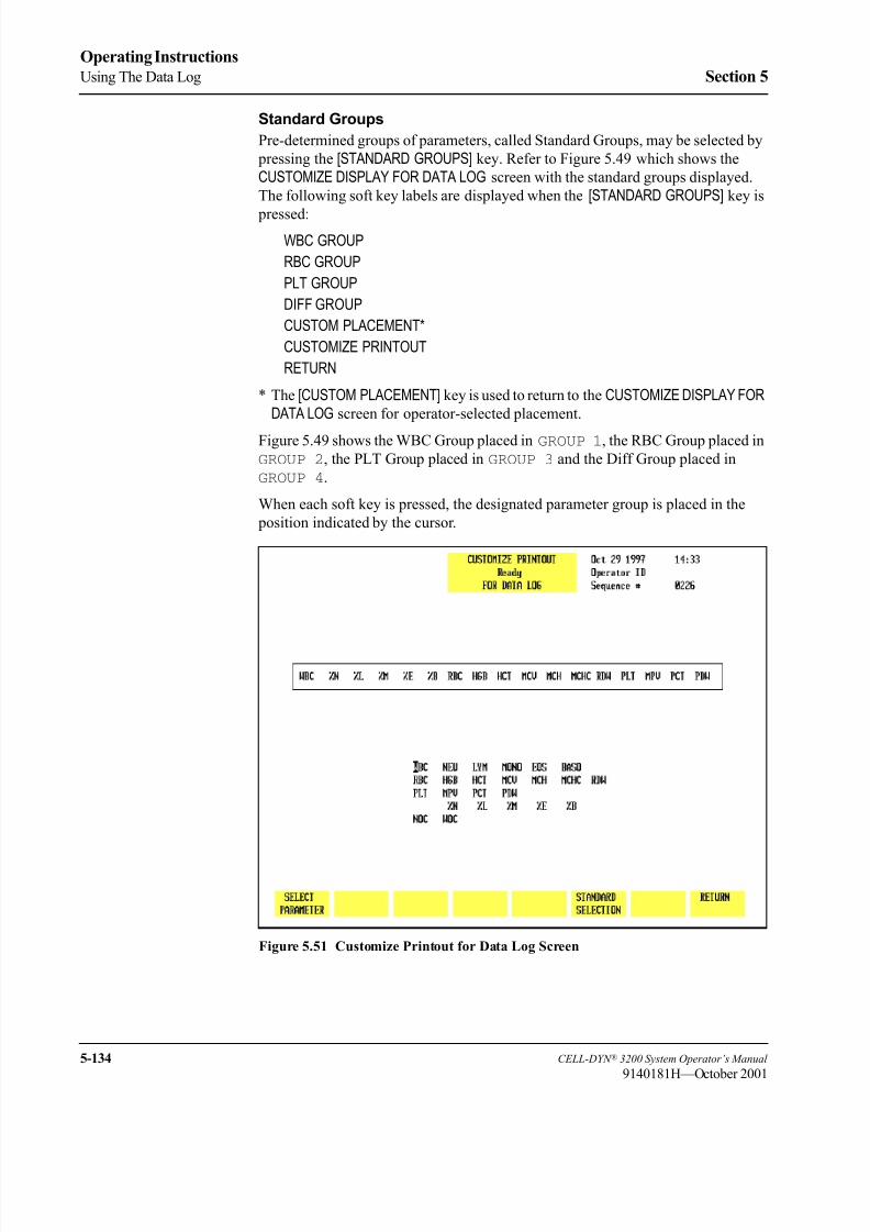
8/21/2019 Equ22-14 CellDyn3200 Op Man
http://slidepdf.com/reader/full/equ22-14-celldyn3200-op-man 292/690
5-134 CELL-DYN ® 3200 System Operator’s Manual
9140181H—October 2001
Operating Instructions
Using The Data Log Section 5
Standard Groups
Pre-determined groups of parameters, called Standard Groups, may be selected by
pressing the [STANDARD GROUPS] key. Refer to Figure 5.49 which shows the
CUSTOMIZE DISPLAY FOR DATA LOG screen with the standard groups displayed.
The following soft key labels are displayed when the [STANDARD GROUPS] key is
pressed:
WBC GROUP
RBC GROUP
PLT GROUP
DIFF GROUP
CUSTOM PLACEMENT*
CUSTOMIZE PRINTOUT
RETURN
* The [CUSTOM PLACEMENT] key is used to return to the CUSTOMIZE DISPLAY FORDATA LOG screen for operator-selected placement.
Figure 5.49 shows the WBC Group placed in GROUP 1, the RBC Group placed in
GROUP 2, the PLT Group placed in GROUP 3 and the Diff Group placed in
GROUP 4.
When each soft key is pressed, the designated parameter group is placed in the
position indicated by the cursor.
Figure 5.51 Customize Printout for Data Log Screen

8/21/2019 Equ22-14 CellDyn3200 Op Man
http://slidepdf.com/reader/full/equ22-14-celldyn3200-op-man 293/690
CELL-DYN ® 3200 System Operator’s Manual 5-135
9140181H—October 2001
Section 5 Operating Instructions
Customize Printout
The [CUSTOMIZE PRINTOUT] key is used to customize the printout format of the
Data Log. (See Figure 5.51.) The following soft key labels are displayed when the
[CUSTOMIZE PRINTOUT] key is pressed:
SELECT PARAMETER/PLACE PARAMETER (The key alternates between the selections.)
STANDARD SELECTION
RETURN
The CUSTOMIZE PRINTOUT FOR DATA LOG screen shows the order (from left to
right) in which the indicated parameters will be printed.
Select Parameter
The [SELECT PARAMETER] key is used to select a parameter designated by the
cursor. When the key is pressed, the selected parameter is highlighted, the label
changes to [PLACE PARAMETER] and a [CANCEL SELECTION] key is displayed.
Place Parameter
The [PLACE PARAMETER] key is used to display the parameter in the location
indicated by the position of the cursor.
Cancel Selection
The [CANCEL SELECTION] key is used to cancel the selection and display the
[SELECT PARAMETER] key.
Standard Selection
The [STANDARD SELECTION] key is used to configure the printout in the pre-
determined print group shown in Figure 5.49. When the key is pressed, the print
group is changed to the Standard Selection.
Return
The [RETURN] key is used to return to the main DATA LOG screen.
8/21/2019 Equ22-14 CellDyn3200 Op Man
http://slidepdf.com/reader/full/equ22-14-celldyn3200-op-man 294/690
5-136 CELL-DYN ® 3200 System Operator’s Manual
9140181H—October 2001
Operating Instructions
Using The Data Log Section 5
Transmit Data
The [TRANSMIT DATA] key is used to transmit a record to a Laboratory Information
System or on-line computer. When the [TRANSMIT DATA] key is pressed, the screen
prompts the operator to enter the starting and ending sequence numbers (from the
lowest to the highest) for the desired transmission. Records may be transmitted
singly or in batches as designated by the sequence number(s).
When the [TRANSMIT DATA] key is pressed, the <Starting Sequence #> field appears
in the upper left corner of the screen and the cursor is positioned in this field. The
operator should enter the sequence number of the first specimen to be transmitted
and press the Enter key. If the number is valid, the system accepts the entry and the
<Ending Sequence #> field appears in the upper left corner of the screen. The
operator should type in the ending sequence number and press Enter. The system
begins transmitting automatically. If only one record is to be transmitted, the
starting and ending sequence number will be the same.
NOTE: Use the ESC key to cancel this function and return to the DATA LOG menu.
Use the Backspace key or left arrow key to cancel an entry and retype the
sequence number.
Because specimen records are shown in summary form on the DATA LOG menu,
only the summary data of these records will be transmitted. No histogram data
accompanies the summary data.
Print Data Log
The [PRINT DATA LOG] key is used to print the Data Log. When the [PRINT DATALOG] key is pressed, the screen prompts the operator to enter the starting and ending
sequence numbers (from the lowest to the highest) for the desired printout. (See
Figure 5.52.)
When the [PRINT DATA LOG] key is pressed, the <Starting Sequence #> fieldappears in the upper left corner of the screen and the cursor is positioned in this
field. The operator should enter the sequence number of the first specimen to be
printed and press the Enter key. If the number is valid, the system accepts the entry
and the <Ending Sequence #> field appears in the upper left corner of the screen.
The operator should type in the ending sequence number and press Enter. The
system begins printing automatically. If only one record is to be printed, the starting
and ending sequence number will be the same.
NOTE: Use the ESC key to cancel this function and return to the DATA LOG menu.
Use the Backspace key or left arrow key to cancel an entry and retype the
sequence number.
Because specimen records are shown in summary form on the DATA LOG menu,only the summary data of these records will be printed. No histogram data
accompanies the summary data.
NOTE: To print histogram data, the operator must press the [DISPLAY SPECIMEN]key in the DATA LOG menu to select and display an individual specimen.
Then, the [PRINT REPORT] key will print the results of the specimen
displayed on the screen, including histograms.

8/21/2019 Equ22-14 CellDyn3200 Op Man
http://slidepdf.com/reader/full/equ22-14-celldyn3200-op-man 295/690
CELL-DYN ® 3200 System Operator’s Manual 5-137
9140181H—October 2001
Section 5 Operating Instructions
Figure 5.52 Print Data Log Screen
Data Log Codes
The Data Log Codes are displayed in the Data Log in the column immediately
preceding the date (see Figure 5.52). These codes are displayed in the following
order:
O — Sample was run in the Open Mode
C — Sample was run in the Closed Mode
N — Incomplete aspiration in the Open Mode
I — Incomplete aspiration in the Closed Mode
K — Flow Error
R — Resistant RBC key was used to run this sample
F — Fragile WBC key was used to run this sample
NOTE: For Background and Latex specimens, only the O and C codes are used.

8/21/2019 Equ22-14 CellDyn3200 Op Man
http://slidepdf.com/reader/full/equ22-14-celldyn3200-op-man 296/690
5-138 CELL-DYN ® 3200 System Operator’s Manual
9140181H—October 2001
Operating Instructions
Using The Data Log Section 5
An example of codes displayed in the Data Log is shown in Figure 5.53.
Figure 5.53 Data Log Codes Screen
Data Log Set Up Procedures
The Data Log may be configured to display and print results in the order selected
by the operator. This section gives instructions for Customizing the Display and
Printout.
Customizing the Data Log Display
The CUSTOMIZE DISPLAY FOR DATA LOG screen displays a matrix showing the four
groups of parameters that will be consecutively displayed on the four Data Log
screens. (Figure 5.54 shows the Standard Groups in the matrix.) A list of all
available parameters is displayed under the matrix. The parameters are selected
from the list and placed in the desired group to customize the display.

8/21/2019 Equ22-14 CellDyn3200 Op Man
http://slidepdf.com/reader/full/equ22-14-celldyn3200-op-man 297/690
CELL-DYN ® 3200 System Operator’s Manual 5-139
9140181H—October 2001
Section 5 Operating Instructions
Figure 5.54 Customize Display for Data Log Screen Showing Standard Groups
The display may be customized by selecting the individual parameters, Standard
Groups of parameters or a combination of the two. In addition to the usual
Hematologic parameters, the following parameters may also be displayed in the
Data Log:
NOC Nuclear Optical Count
EMPTY Inserts an empty column in the display
To Customize the Data Log Display
1. In the main DATA LOG screen, press [CUSTOMIZE DATA LOG] to display the
CUSTOMIZE DISPLAY FOR DATA LOG screen.
2. If necessary, press [CUSTOM PLACEMENT] to display the CUSTOMIZEDISPLAY FOR DATA LOG screen and key labels for custom placement.
3. Use the Arrow keys on the keyboard to move the cursor to the desired
parameter in the listing under the matrix.
4. Press [SELECT PARAMETER]. The selected parameter is highlighted and the
cursor moves to the first position in Group 1.NOTE: The key label changes to [PLACE PARAMETER] and a [CANCEL
SELECTION] key is displayed.
5. If necessary, use the Arrow keys on the keyboard to move the cursor to the
desired location and press [PLACE PARAMETER].
NOTE: When the [PLACE PARAMETER] key is pressed, the selected
parameter is displayed in the position indicated by the cursor and
the cursor is then advanced to the next position in the group.

8/21/2019 Equ22-14 CellDyn3200 Op Man
http://slidepdf.com/reader/full/equ22-14-celldyn3200-op-man 298/690
5-140 CELL-DYN ® 3200 System Operator’s Manual
9140181H—October 2001
Operating Instructions
Using The Data Log Section 5
6. Repeat steps 3–5 until all selections have been made.
7. If desired, press the Print Screen key on the keyboard to obtain a printout of
the selected groups.
8. Press [RETURN] to return to the DATA LOG screen.
9. The Data Log is displayed configured with the selected parameters.
Standard Groups
The Data Log display may also be customized with pre-determined groups
(Standard Groups) of parameters using the [STANDARD GROUPS] key. Figure 5.54
shows the WBC Group placed in GROUP 1, the RBC Group placed in GROUP 2,
the PLT Group placed in GROUP 3 and the Diff Group placed in GROUP 4.
To Customize the Data Log Display for Standard Groups
1. From the main DATA LOG screen, press [CUSTOMIZE DATA LOG] to display the
CUSTOMIZE DISPLAY FOR DATA LOG screen.
2. Press [STANDARD GROUPS] to display the CUSTOMIZE DISPLAY FOR DATA
LOG screen and key labels for Standard Groups.
3. Use the Arrow keys on the keyboard to move the cursor to the desired group
(1–4) location.
NOTE: This number indicates the order in which the group of parameters
will be displayed (Group 1 on the first screen, Group 2 on the
second, etc.).
4. Press the soft key corresponding to the desired parameter group. This group
is displayed in the position indicated by the cursor.
5. Repeat steps 3 and 4 until all desired groups have been selected.
6. If desired, press the Print Screen key on the keyboard to obtain a printout of
the configuration.7. Press [RETURN] to return to the DATA LOG screen.
8. The Data Log is displayed configured with the standard groups of
parameters.

8/21/2019 Equ22-14 CellDyn3200 Op Man
http://slidepdf.com/reader/full/equ22-14-celldyn3200-op-man 299/690
CELL-DYN ® 3200 System Operator’s Manual 5-141
9140181H—October 2001
Section 5 Operating Instructions
Figure 5.55 Customize Printout for Data Log Screen Showing Customized Print
Group
Customizing the Printout
The CUSTOMIZE PRINTOUT FOR DATA LOG screen (see Figure 5.55) shows the
group of parameters that will be printed on a Data Log printout. A list of the
available parameters is displayed under the group. The parameters are selected
from the list and placed in the desired position to customize the printout. In additionto the usual Hematologic parameters, the following parameter may also be printed
in the Data Log:
NOC — Nuclear Optical Count

8/21/2019 Equ22-14 CellDyn3200 Op Man
http://slidepdf.com/reader/full/equ22-14-celldyn3200-op-man 300/690
5-142 CELL-DYN ® 3200 System Operator’s Manual
9140181H—October 2001
Operating Instructions
Using The Data Log Section 5
To Customize the Data Log Printout
1. From the main DATA LOG screen, press [CUSTOMIZE DATA LOG] followed by
[CUSTOMIZE PRINTOUT].
2. Use the Arrow keys on the keyboard to move the cursor to the desired
parameter in the list displayed under the printout group.
3. Press [SELECT PARAMETER]. The selected parameter is highlighted and the
cursor moves to the first position in the group.
NOTE: The key label changes to [PLACE PARAMETER] and a [CANCELSELECTION] key is displayed.
4. If necessary, use the Arrow keys on the keyboard to move the cursor to the
desired location and press [PLACE PARAMETER].
NOTE: When the [PLACE PARAMETER] key is pressed, the selected
parameter is displayed in the position indicated by the cursor and
the cursor then advances to the next parameter in the list displayed
under the printout group.
5. Repeat steps 2–4 until all selections have been made.6. If desired, press the Print Screen key on the keyboard to obtain a printout of
the configuration.
7. Press [RETURN] twice to return to the DATA LOG screen.
Standard Selection
The [STANDARD SELECTION] key is used to automatically arrange the parameters
in a predetermined print group.

8/21/2019 Equ22-14 CellDyn3200 Op Man
http://slidepdf.com/reader/full/equ22-14-celldyn3200-op-man 301/690
CELL-DYN ® 3200 System Operator’s Manual 5-143
9140181H—October 2001
Section 5 Operating Instructions
Data Review from the Data Log
Use the Page Up/Down keys and arrow keys to view Data Log records and
parameters within a record as described earlier in Scrolling Through the Data Log .
Displaying A RecordA copy of the RUN screen may be displayed for all 10,000 records in the
CELL-DYN 3200 Data Log. A record is displayed by positioning the cursor at the
record in the Data Log listing and pressing [DISPLAY SPECIMEN]. The record is
displayed on the DISPLAY SPECIMEN screen. (See Figure 5.56.)
Figure 5.56 Display Specimen Screen
To Display a Record
1. From the MAIN MENU screen, press [DATA LOG].
2. Use the Arrow keys on the keyboard to move the cursor to the desired record
(use the Page Up and Page Down keys to scroll between pages).
3. Press [DISPLAY SPECIMEN] to display the RUN screen for the selected record.
4. If desired, press [PRINT REPORT] to obtain a printout.NOTE: If a color printing has been selected, the key label changes to
[COLOR PRINT] and a color printout is generated when the key is
pressed.
5. The [PREVIOUS SPECIMEN] or [NEXT SPECIMEN] key may now be used to
display records listed in the Data Log which are adjacent to the one currently
displayed.

8/21/2019 Equ22-14 CellDyn3200 Op Man
http://slidepdf.com/reader/full/equ22-14-celldyn3200-op-man 302/690
5-144 CELL-DYN ® 3200 System Operator’s Manual
9140181H—October 2001
Operating Instructions
Using The Data Log Section 5
To Find a Record
Figure 5.57 Find Specimen Screen
1. From the MAIN MENU screen, press [DATA LOG].
2. If the desired record is not displayed on the screen, press [FIND SPECIMEN] todisplay the DATA LOG SEARCH screen.
3. Use the Arrow keys on the keyboard to move the cursor to the desiredidentifier: Sequence Number, Specimen ID Number or Name. Refer to
Figure 5.57.
4. Type the appropriate information and press the Enter key on the keyboard to
start the search.
NOTE: If necessary, you may press the Escape (ESC) key or the Enter key
on the keyboard to exit from the search function and return to the
DATA LOG screen.
5. If the requested record is available, the screen displays the Data Log page
containing it. (The cursor is located at the sequence number of the record.)

8/21/2019 Equ22-14 CellDyn3200 Op Man
http://slidepdf.com/reader/full/equ22-14-celldyn3200-op-man 303/690
CELL-DYN ® 3200 System Operator’s Manual 5-145
9140181H—October 2001
Section 5 Operating Instructions
To Edit a Record
The Patient Demographics and the Parameter and Patient Limits Sets may be edited
for each record. (See Figure 5.58.)
Figure 5.58 Edit Specimen Screen
To Edit a Specimen
1. From the MAIN MENU screen, press [DATA LOG].2. Locate the desired record and press [DISPLAY SPECIMEN] followed by [EDIT
SPECIMEN].
3. Use the Arrow keys on the keyboard to move the cursor to the line that will
be edited and type the appropriate information. Press the Enter key on the
keyboard to save the entry.
4. Press [CONFIRM] to display the RUN screen for the edited result.
5. If desired, press [PRINT REPORT] or [COLOR PRINT] to obtain a printout.
8/21/2019 Equ22-14 CellDyn3200 Op Man
http://slidepdf.com/reader/full/equ22-14-celldyn3200-op-man 304/690
5-146 CELL-DYN ® 3200 System Operator’s Manual
9140181H—October 2001
Operating Instructions
References Section 5
References
1. NCCLS Standard H3-A3, Procedure for the Collection of Diagnostic BloodSpecimens by Venipuncture —Third Edition; Approved Standard (1991).
2. NCCLS Standard H4-A3, Procedure for the Collection of Diagnostic Blood
Specimens by Skin Puncture —Third Edition; Approved Standard (1991).
3. ICSH, Protocol for Evaluation of Automated Blood Cell Counters, Clinical
and Laboratory Hematology 1988, 10:203, 212.

8/21/2019 Equ22-14 CellDyn3200 Op Man
http://slidepdf.com/reader/full/equ22-14-celldyn3200-op-man 305/690
CELL-DYN ® 3200 System Operator’s Manual 6-1
9140181H—October 2001
Section 6 Calibration Procedures
ec on a rat on roce ures
Overview
The CELL-DYN 3200 System is calibrated at the factory just prior to shipment. AnAbbott Field Service Representative will assist the operator in confirming the
calibration during instrument installation. Calibration may be performed using
commercial calibrator or fresh whole blood samples. Only the directly measured
parameters — WOC, NOC, RBC, HGB, MCV, PLT, and MPV — may be
calibrated.
Calibration should be confirmed on a regular basis according to the laboratory’s
schedule for maintaining good laboratory practice.
On-board quality control programs are designed to provide continual monitoring
and verification of instrument calibration. The laboratory should make the decision
to recalibrate based on the performance of the CELL-DYN 3200 in these quality
control programs.
Instrument calibration is discussed in the following order:
• General Information
• Pre-Calibration Procedures
• Calibration Menu and Soft Keys
• Auto-Cal Method
• Enter Factor Method
• Calibration Worksheets

8/21/2019 Equ22-14 CellDyn3200 Op Man
http://slidepdf.com/reader/full/equ22-14-celldyn3200-op-man 306/690
6-2 CELL-DYN ® 3200 System Operator’s Manual
9140181H—October 2001
Calibration Procedures
Overview Section 6
NOTES

8/21/2019 Equ22-14 CellDyn3200 Op Man
http://slidepdf.com/reader/full/equ22-14-celldyn3200-op-man 307/690
CELL-DYN ® 3200 System Operator’s Manual 6-3
9140181M—June 2004
Section 6 Calibration Procedures
General Information
The CELL-DYN 3200 System has two modes of operation:
• Open Mode
• Closed Mode
Both the Open and Closed Modes are calibrated individually. It is recommended
that the primary mode (Open Mode) be calibrated first.
NOTE: The procedure for calibrating Closed Mode differs slightly between the
SL and CS models.
Three methods of calibration are available on the CELL-DYN 3200 System:
Auto-Calibration, Enter Factor, and Latex.
1. The Auto-Calibration method is designed to quickly and easily calibrate thesystem, using commercial control material or fresh whole blood.
a. On the CS model, Auto-Calibration can be used in both the Open and
Closed Modes.
b. On the SL model, Auto-Calibration can be used only in the Open Mode.
The Enter Factor Method must be used to calibrate the Closed Mode.
2. The Enter Factor method is a manual procedure for calibrating the
instrument. With this method, Fresh Whole Blood is normally used. The
Enter Factor may also be used with calibrator in the Open Mode.
3. Latex material may also be used to calibrate the instrument but this procedure
should only be performed by Abbott service personnel.

8/21/2019 Equ22-14 CellDyn3200 Op Man
http://slidepdf.com/reader/full/equ22-14-celldyn3200-op-man 308/690
6-4 CELL-DYN ® 3200 System Operator’s Manual
9140181H—October 2001
Calibration Procedures
General Information Section 6
When to Calibrate
Scheduled calibration of the CELL-DYN 3200 should conform to the guidelines
established by regulatory agencies.
Calibration should be confirmed on a regular basis according to the requirements
governing quality control in your laboratory. In keeping with good laboratory practices, this should include daily confirmation on each shift and following a
reagent lot number change.
Unscheduled calibration is indicated following service adjustments performed by
Abbott Field Service Representatives, such as major component changes.
Unscheduled calibration is also necessary when indicated by the results of the
Quality Control program. Quality Control includes (1) statistical computations and
Westgard® Rules for commercial or patient controls, and (2) monitoring of patient
samples for WBC parameters with moving averages and RBC parameters using
Bull’s Moving Average Program (X-B).
The laboratory should make the decision to recalibrate based on the results of theinstrument’s performance, as indicated by these quality control programs.
However, calibration should be considered as the very last step in a troubleshooting
sequence. Performing unnecessary calibrations may mask an underlying problem
with the instrument’s performance.
Calibration is also recommended following the replacement of any major
instrument component, such as the Shear Valve, that could affect the accuracy of
the instrument. Calibration should also be confirmed by running the same samples
used to calibrate the instrument to test the accuracy of the reported results. The
procedures for confirming calibration are described in subsections Auto-Cal
Method and Enter Factor Method .
8/21/2019 Equ22-14 CellDyn3200 Op Man
http://slidepdf.com/reader/full/equ22-14-celldyn3200-op-man 309/690
CELL-DYN ® 3200 System Operator’s Manual 6-5
9140181M—June 2004
Section 6 Calibration Procedures
Calibration Materials
WARNING: Potential Biohazard. Consider all specimens and reagents,
controls, calibrators, etc., that contain human blood or serum as potentially
infectious. Wear gloves, lab coats, and safety glasses, and follow other
biosafety practices as specified in the OSHA Bloodborne Pathogen Rule
(29 CFR Part 1910.1030) or other equivalent biosafety procedures.
Three types of calibration materials can be used to calibrate the CELL-DYN 3200:
CELL-DYN Calibrators may be used to calibrate the Open Mode. The
same Calibrator used to calibrate should also be used to confirm calibration.
The Closed Mode is then calibrated to match the Open Mode using fresh
whole blood samples.
• Fresh Whole Blood
Fresh whole blood may be used to calibrate the Open and Closed Modes.
The Auto-Cal method uses one sample to calibrate compared to the Enter
Factor method which uses five samples. Reference values are obtained byrunning the sample(s) on a reference instrument, using acceptable reference
methodology, and calculating the mean reference value for each parameter.
The same sample(s) used to calibrate should also be used to confirm
calibration.
• Polystyrene Microspheres
Polystyrene Microspheres are used to calibrate the Optical Bench. This
calibration is verified by an Abbott representative during installation of the
instrument.
Instrument LogbookCreate a logbook for the instrument. This logbook should contain all necessary
calibration documentation and other information that is pertinent to your
instrument. Suggested sections that you may wish to include in the logbook are:
• Installation documentation
• Laboratory’s operating procedure
• Quality control
• Calibration
• Maintenance
• Reagent lot number changes
• Troubleshooting• Problem resolution
• Service calls
• Software upgrades
This logbook should be stored near the instrument and be accessible to all operators
and Abbott Service Personnel.

8/21/2019 Equ22-14 CellDyn3200 Op Man
http://slidepdf.com/reader/full/equ22-14-celldyn3200-op-man 310/690
6-6 CELL-DYN ® 3200 System Operator’s Manual
9140181H—October 2001
Calibration Procedures
General Information Section 6
NOTES

8/21/2019 Equ22-14 CellDyn3200 Op Man
http://slidepdf.com/reader/full/equ22-14-celldyn3200-op-man 311/690
CELL-DYN ® 3200 System Operator’s Manual 6-7
9140181L—July 2003
Section 6 Calibration Procedures
Pre-Calibration Procedures
OverviewThe Pre-Calibration Procedures in this subsection verify proper instrument
performance to ensure a successful calibration. These steps should be completed
just prior to beginning the calibration procedure itself. If problems are detected
during these checks, DO NOT ATTEMPT TO CALIBRATE THE INSTRUMENT.
If necessary, CALL ABBOTT CUSTOMER SERVICE FOR ASSISTANCE. After
the problems have been resolved, repeat the Pre-Calibration Procedures to verify
proper performance.
NOTE: Instrument calibration, including the pre-calibration procedures, should
be completed without interruption.
Calibration Guidelines
1. Always perform the Daily, Weekly and Monthly scheduled maintenance as
directed in Section 9: Service and Maintenance before calibrating the
instrument. Instrument cleanliness is essential for accurate calibration.
Therefore, each laboratory should perform any additional maintenance
according to its requirements.
2. Use only recommended CELL-DYN reagents.
3. Verify the precision for the Open and Closed Modes prior to calibration as
directed in the Pre-Calibration Procedures Checklist.
NOTE: If necessary, refer to the directions for customizing the display and
printout of a QC file given in Section 5: Operating Instructions; Subsection: Set Up Instructions.
4. Select and process all whole blood samples according to the requirements
given in Fresh Whole Blood Requirements later in this section.
5. Try to obtain a sufficient amount of sample (calibrator or fresh whole blood)
so that the same sample can be used for precision check, calibration in Open
and Closed Modes, and confirmation in Open and Closed Modes. If sufficient
sample is not available, use a different sample for precision check.
6. Be certain that all samples used are brought to room temperature and mixed
well before aspiration.
7. Be certain that the technologist performing the calibration has read and
understands the information contained in the package insert for the calibrator.
8. Be certain that the technologist performing the calibration has read and
understands the calibration procedure(s) and the appropriate overviews
described in this manual.
9. Confirm that reagent containers are at least one third full. Replace them as
necessary.

8/21/2019 Equ22-14 CellDyn3200 Op Man
http://slidepdf.com/reader/full/equ22-14-celldyn3200-op-man 312/690
6-8 CELL-DYN ® 3200 System Operator’s Manual
9140181M—June 2004
Calibration Procedures
Pre-Calibration Procedures Section 6
10. Confirm that the waste container is no more than half full. If necessary, empty
it as described in Section 8: Hazards; Subsection: Handling and Disposing
of Biohazardous Materials.
11. Confirm that background counts are within limits. If the system has been idle
for fifteen minutes or more, a Background count should be run immediately
prior to running any calibration specimens.12. Confirm that the Operator ID number is entered.
Calibration Materials
Calibrator Requirements
• For commercial calibrators, follow the directions given in the package insert.
Be certain to carefully read and follow directions given for warming and
mixing.
• Auto-Cal Method: The calibrator should be cycled for a minimum of 6 and a
maximum of 10 consecutive runs when calibrating the Open Mode.
• Enter Factor Method: The calibrator should be cycled for a minimum of 6
consecutive runs. Additional samples and/or repetitions of the specimens
may be used to achieve calibration accuracy beyond NCCLS
recommendations.
Fresh Whole Blood Requirements
The International Committee for Standardization in Hematology (ICSH) defines a
fresh blood sample as one available for processing less than four hours following
venous sampling.
Normal Sample• Blood samples should be from the general patient population, with values for
all parameters which are within the laboratory’s normal range.
• All cellular morphology must be normal.
• No known interfering substances should be present (for example, lipemia,
icterus, medications).
• All samples must be properly collected in the EDTA anticoagulant used by
the laboratory.
• Each tube should contain at least 90% of the nominal collection volume of
blood.
• Samples should be at room temperature and mixed properly.

8/21/2019 Equ22-14 CellDyn3200 Op Man
http://slidepdf.com/reader/full/equ22-14-celldyn3200-op-man 313/690
CELL-DYN ® 3200 System Operator’s Manual 6-9
9140181H—October 2001
Section 6 Calibration Procedures
Sample Age
• All blood samples should be less than four hours old when calibration
begins.1 These samples must be less than eight hours old by the time
calibration is completed.
• No more than two hours should elapse between the CELL-DYN 3200 run and
the assay by reference methodology or reference instrument. If samples are
run on the CELL-DYN 3200 first, assay by reference methodology should be
completed within one hour. (Certain reference methodologies are sensitive to
RBC swelling caused by in vitro deoxygenation.)
Sample Amount
The whole blood sample volume should be at least 12 mL to accomplish the
following:
• Obtain reference values on a reference instrument prior to calibration.
• Calibrate both the Open and Closed Modes.
• Confirm calibration of both modes.
NOTE: Because only one fresh whole blood sample is used in Auto-Cal, it
is important that a representative sample be selected to calibrate the
instrument. A sample containing abnormalities may adversely
affect calibration.
Number of Cycles
• Samples should be assayed first on a reference instrument or by reference
methodology and then on the CELL-DYN 3200.
• Auto-Cal Method: A single fresh whole blood sample should be cycled for
10 consecutive runs when calibrating in either Open or Closed Mode.• Enter Factor Method: Five fresh whole blood samples should be cycled twice
each for a total of at least ten runs when calibrating in either Open or Closed
Mode. Additional samples and/or repetitions of the specimens may be used
to achieve calibration accuracy beyond NCCLS recommendations.
Pre-Calibration Check List
Follow the procedures outlined in the Pre-Calibration Check List to ensure the
instrument is ready for calibration. Use the Problem List to note any problems
encountered. Make copies of both lists as needed.
NOTE: Always complete the Pre-Calibration procedures before beginning any
calibration.

8/21/2019 Equ22-14 CellDyn3200 Op Man
http://slidepdf.com/reader/full/equ22-14-celldyn3200-op-man 314/690
6-10 CELL-DYN ® 3200 System Operator’s Manual
9140181L—July 2003
Calibration Procedures
Pre-Calibration Procedures Section 6
CELL-DYN 3200
PRE-CALIBRATION PROCEDURES CHECK LIST
Instrument: Date:
Operator:
1._______ Perform all required maintenance.
2._______ Verify that all reagent containers are at least 1/3 full and the waste container is less than 1/2 full.
3._______ Verify that the reagents have not reached the expiration date.
Diluent/Sheath: Lot #____________ Exp. date _______
HGB Lyse: Lot #____________ Exp. date _______
WBC Lyse: Lot #____________ Exp. date _______
4._______ If applicable, verify that the calibrator has not reached the expiration date.
Lot #____________ Exp. date _______
5._______ After the maintenance has been completed, verify that the Background counts are within the
acceptable limits. Record the background counts below or attach a printout to this document.
WOC < 0.10 ________
NOC < 0.10 ________
RBC < 0.02 ________
HGB < 0.10 ________
PLT < 5.0 ________
6._______ Verify the Open Mode precision by analyzing a fresh, normal whole blood sample 10 times in
succession. Select an empty QC file in the SPECIMEN TYPE menu. Make sure Open Mode is
selected. Run the sample 10 times. When the runs have been completed, write the CVs displayed
on the screen in the appropriate spaces below or attach a file printout to this document.
PARAMETER CV% LIMIT CV%
WOC < 2.7% ________
NOC < 2.7% ________
RBC < 1.5% ________
HGB < 1.0% ________
MCV < 1.0% ________
PLT < 4.0% ________
7.______ If the CV for all parameters fall within the limits, go to step 8 to verify Closed Mode precision. If a
parameter’s CV exceeds the limit, run the sample again. If the over-limit condition persists, call
Abbott Customer Service for assistance.

8/21/2019 Equ22-14 CellDyn3200 Op Man
http://slidepdf.com/reader/full/equ22-14-celldyn3200-op-man 315/690
CELL-DYN ® 3200 System Operator’s Manual 6-11
9140181H—October 2001
Section 6 Calibration Procedures
8.______ Verify the Closed Mode precision as follows:
a. For the CS model: Use the same sample as in the Open Mode. Select an
empty QC file in the SPECIMEN TYPE menu. Make sure Closed Mode is
selected. Run the sample 10 times.
b. For the SL model: Use the same sample as in the Open Mode. Aliquot the
blood in equal volumes into 10 5-mL tubes (each tube should contain a
minimum of 1 mL of sample) containing no anticoagulant. Select an
empty QC file in the SPECIMEN TYPE menu. Make sure Closed Mode is
selected. Place the tubes in a rack, place the rack in the “loading”
position, and press the [START LOADER] key.
c. When all the samples have been processed on either the CS or SL model,
record the CVs below or attach a file printout to this document.
PARAMETER CV% LIMIT CV%
WOC < 2.7% ________
NOC < 2.7% ________
RBC < 1.5% ________
HGB < 1.0% ________
MCV < 1.0% ________
PLT < 4.0% ________
9.______ If any problems are detected during the procedures outlined above, document them on the form on
the following page. Make copies of this form as necessary.

8/21/2019 Equ22-14 CellDyn3200 Op Man
http://slidepdf.com/reader/full/equ22-14-celldyn3200-op-man 316/690
6-12 CELL-DYN ® 3200 System Operator’s Manual
9140181H—October 2001
Calibration Procedures
Pre-Calibration Procedures Section 6
Problems Detected
________________________________________________________________________________________
________________________________________________________________________________________
________________________________________________________________________________________
________________________________________________________________________________________
________________________________________________________________________________________
________________________________________________________________________________________
________________________________________________________________________________________
________________________________________________________________________________________
________________________________________________________________________________________
________________________________________________________________________________________
________________________________________________________________________________________
________________________________________________________________________________________
________________________________________________________________________________________
________________________________________________________________________________________
________________________________________________________________________________________
________________________________________________________________________________________
________________________________________________________________________________________
________________________________________________________________________________________
________________________________________________________________________________________
________________________________________________________________________________________
________________________________________________________________________________________
________________________________________________________________________________________
________________________________________________________________________________________
________________________________________________________________________________________
________________________________________________________________________________________
________________________________________________________________________________________
________________________________________________________________________________________
________________________________________________________________________________________
________________________________________________________________________________________

8/21/2019 Equ22-14 CellDyn3200 Op Man
http://slidepdf.com/reader/full/equ22-14-celldyn3200-op-man 317/690
CELL-DYN ® 3200 System Operator’s Manual 6-13
9140181H—October 2001
Section 6 Calibration Procedures
Calibration Menu
OverviewThe CALIBRATION menu is accessed from the MAIN MENU by pressing the
[CALIBRATION] key. The CALIBRATION menu displays the current calibration factors
for the mode indicated, the date and time the factors were entered, and the operator
ID. Figure 6.1 displays the calibration factors for the Open Mode, and Figure 6.2
displays the calibration factors for the Closed Mode. Note that Open Sampler is
displayed in both figures, indicating Open Mode. The mode is independent of the
calibration factors being displayed.
The following soft key labels are displayed:
ENTER FACTOR
CALIBRATION LOG AUTO-CALIBRATE
OPEN SAMPLER/CLOSED SAMPLER (Key label alternates between selections)
MAIN
The function of each key is discussed briefly in this section.
Figure 6.1 Calibration Menu Screen Displaying Open Sampler Calibration Factors

8/21/2019 Equ22-14 CellDyn3200 Op Man
http://slidepdf.com/reader/full/equ22-14-celldyn3200-op-man 318/690
6-14 CELL-DYN ® 3200 System Operator’s Manual
9140181H—October 2001
Calibration Procedures
Calibration Menu Section 6
Figure 6.2 Calibration Menu Screen Displaying Closed Sampler Calibration
Factors

8/21/2019 Equ22-14 CellDyn3200 Op Man
http://slidepdf.com/reader/full/equ22-14-celldyn3200-op-man 319/690
CELL-DYN ® 3200 System Operator’s Manual 6-15
9140181H—October 2001
Section 6 Calibration Procedures
Calibration Menu Soft Keys
Enter Factor
The [ENTER FACTOR] key is used to display the ENTER CALIBRATION FACTOR
screen which displays the current whole blood factors for the displayed mode (refer
to Figure 6.3). The soft keys available in this screen are:
RESTORE FACTORS
RESET ALL TO 1.000
RETURN
Restore Factors
The [RESTORE FACTORS] key is used to restore the previous calibration factors.
This key is active only immediately after factors have been changed.
Reset all to 1.000
The [RESET ALL TO 1.000] key is used to reset all of the calibration factors to 1.000.
Return
The [RETURN] key is used to return to the main CALIBRATION menu.
Figure 6.3 Enter Calibration Factor Screen

8/21/2019 Equ22-14 CellDyn3200 Op Man
http://slidepdf.com/reader/full/equ22-14-celldyn3200-op-man 320/690
6-16 CELL-DYN ® 3200 System Operator’s Manual
9140181H—October 2001
Calibration Procedures
Calibration Menu Section 6
Calibration Log
The [CALIBRATION LOG] key is used to display the CALIBRATION LOG screen for the
Open or Closed Mode (refer to Figure 6.4). The soft keys available in this screen
are:
OPEN SAMPLER/CLOSED SAMPLER
PRINT LOG
RETURN
The CALIBRATION LOG holds 10 entries. The last 5 entries are displayed on the
screen. To display any previous entries, press the Page Up key on the keyboard.
NOTE: When the log is full, subsequent entries cause the oldest entry to be
deleted and the remaining entries to move up one line, so that the current
factors are added to the bottom of the list. Therefore, the log should be
printed periodically for purposes of documentation.
The log displays the DATE, TIME, OPERATOR ID, CALIBRATION FACTORS
and a line for COMMENTS.
NOTE: The letters in parentheses after each factor indicate the method of factor
derivation: F = Factory, A = Auto-Cal, E = Enter Factor
(manual factor entry).
Type any comments in the COMMENTS field. Press the Enter key on the keyboard
to save the entry and advance the cursor.
NOTE: Comments may be added to the Calibration Log only after a calibration
factor is changed or reentered.
Open Sampler/Closed Sampler
The [OPEN SAMPLER/CLOSED SAMPLER] key is used to display the calibration
factors for the displayed mode. This key toggles between the Open and ClosedSampler Calibration Factors.
Print Log
The [PRINT LOG] key is used to print the Calibration Log for the displayed mode.
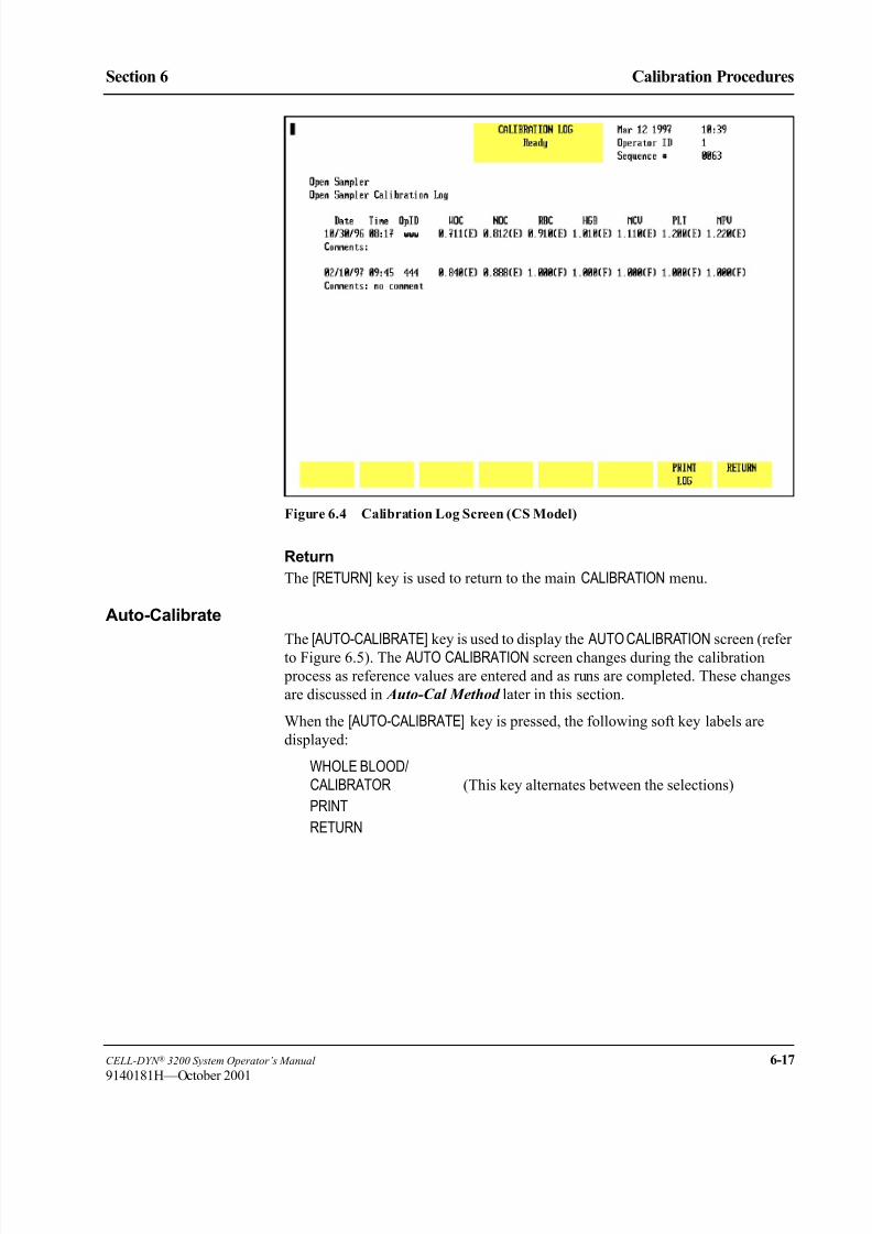
8/21/2019 Equ22-14 CellDyn3200 Op Man
http://slidepdf.com/reader/full/equ22-14-celldyn3200-op-man 321/690
CELL-DYN ® 3200 System Operator’s Manual 6-17
9140181H—October 2001
Section 6 Calibration Procedures
Figure 6.4 Calibration Log Screen (CS Model)
Return
The [RETURN] key is used to return to the main CALIBRATION menu.
Auto-Calibrate
The [AUTO-CALIBRATE] key is used to display the AUTO CALIBRATION screen (refer
to Figure 6.5). The AUTO CALIBRATION screen changes during the calibration
process as reference values are entered and as runs are completed. These changes
are discussed in Auto-Cal Method later in this section.
When the [AUTO-CALIBRATE] key is pressed, the following soft key labels are
displayed:
WHOLE BLOOD/CALIBRATOR (This key alternates between the selections)
RETURN

8/21/2019 Equ22-14 CellDyn3200 Op Man
http://slidepdf.com/reader/full/equ22-14-celldyn3200-op-man 322/690
6-18 CELL-DYN ® 3200 System Operator’s Manual
9140181H—October 2001
Calibration Procedures
Calibration Menu Section 6
Figure 6.5 Auto Calibration Screen
The [WHOLE BLOOD] and [CALIBRATOR] keys alternate to display which type of
calibration material is being used. This information is displayed in the upper left
corner of the screen and stored with the updated calibration factors on the
Calibration Log.
The [PRINT] key is used to print the data displayed on the screen.
8/21/2019 Equ22-14 CellDyn3200 Op Man
http://slidepdf.com/reader/full/equ22-14-celldyn3200-op-man 323/690
CELL-DYN ® 3200 System Operator’s Manual 6-19
9140181M—June 2004
Section 6 Calibration Procedures
Auto-Cal Method
OverviewThe Auto-Cal program provides an automated calibration method that prepares the
CELL-DYN 3200 System for calibration, calculates new calibration factors, and
calibrates the instrument.
NOTE: Always complete the Pre-Calibration procedures before beginning any
calibration.
Methodology
The instrument should be calibrated in both Open and Closed Modes. CELL-DYN
Calibrator is used to calibrate the Open Mode and normal, fresh whole blood is
used to calibrate the Closed Mode.
NOTE: Auto-Calibration is not available in the Closed Mode on the SL model. To
calibrate Closed Mode, see Calibration Procedure — Mode to Mode in
subsection Enter Factor Method .
The same reference values and the same samples should be used when calibrating
both modes. It is recommended that the Open Mode be calibrated first using
CELL-DYN Calibrator. The Closed Mode is then calibrated to match the Open
Mode using fresh, normal whole blood samples.
When samples are run, Auto-Cal does the following:
1. Accepts up to ten consecutive sample runs for either calibrator or fresh whole
blood samples.
2. Compares sample results against internal precision and reference checks,
highlighting results that fail these checks.
3. Calculates the new calibration factors (Mean Factors) and Factor % Diff
values.
4. Compares the Factor % Diff values to ranges in an internal table to determine
which parameters require calibration.
NOTE: These ranges are shown in the Calibration Range Criteria
worksheets (Worksheet 3 for Open Mode and Worksheet 6 for
Closed Mode) in Manual Calibration Worksheets at the end of this
section.
5. Highlights Factor % Diff values which require calibration or which are over-
limit.

8/21/2019 Equ22-14 CellDyn3200 Op Man
http://slidepdf.com/reader/full/equ22-14-celldyn3200-op-man 324/690
6-20 CELL-DYN ® 3200 System Operator’s Manual
9140181M—June 2004
Calibration Procedures
Auto-Cal Method Section 6
Determining Reference Values
The minimum and maximum values for each parameter, displayed above the
reference value fields, apply to both calibrator material and fresh whole blood.
Calibrator
Obtain the reference values from the assay sheet that is packaged with thecalibrator material.
NOTE: For parameters whose assigned value exceeds the Auto-Calibration pre-
set limits, use the manual method for calibration.
Fresh Whole Blood
Follow the procedure below to determine the calibration reference values using
fresh whole blood.
NOTE: No more than two hours should elapse between determining the
Reference Mean Values and performing the calibration.
WARNING: Potential Biohazard. Consider all specimens and reagents,
controls, calibrators, etc., that contain human blood or serum as potentiallyinfectious. Wear gloves, lab coats, and safety glasses and follow other
biosafety procedures as specified in the OSHA Bloodborne Pathogen Rule
(29 CFR 1910.1030) or other equivalent biosafety procedures.
1. Go to a reference hematology instrument or use appropriate hematology
methods with one sample of normal, fresh whole blood.
NOTE: The Auto-Cal method is designed for 1 sample. If you want to use
more than one fresh whole blood, you must use the Enter Factor
method.
2. Run a minimum of 10 replicates from this sample on the reference
instrument.
NOTE: Because the same sample will be used to first obtain reference
values on a reference instrument then to calibrate in the Open and
Closed Modes, it is important to begin with a sufficient amount of
sample.
3. If a mean value for each parameter based on at least 10 runs is not
automatically calculated by the reference hematology instrument or
hematology methods, use a calculator to determine the Reference Mean for
each parameter. For example:
The cumulative Reference WBC Mean is 6.53 when the WBC results from
each run are as follows:
• RUN 1 = 6.6, RUN 2 = 6.4, RUN 3 = 6.7• RUN 4 = 6.5, RUN 5 = 6.6, RUN 6 = 6.4
• RUN 7 = 6.7, RUN 8 = 6.3, RUN 9 = 6.5
• RUN 10 = 6.6
The cumulative mean of 6.53 equals the sum of the values (65.3) divided by
the 10 runs.
4. Save these values; they will be used to calibrate the CELL-DYN 3200
System.

8/21/2019 Equ22-14 CellDyn3200 Op Man
http://slidepdf.com/reader/full/equ22-14-celldyn3200-op-man 325/690
CELL-DYN ® 3200 System Operator’s Manual 6-21
9140181K—July 2002
Section 6 Calibration Procedures
Auto-Cal Menu
When the [AUTO-CALIBRATE] key is pressed in the main CALIBRATION menu, the
AUTO-CALIBRATION menu is displayed (refer to Figure 6.6). Reference values are
entered on this screen.
The Spec ID field in the upper left corner of the screen defaults to “CAL#01” toidentify the sample as a “Calibration sample.” This field is user-definable and
accepts up to 6 alphanumeric characters. As each calibration sample is run, the
calibration program adds a “-” and the run number from “01” to “10.”
Figure 6.6 Auto Calibration Screen
Start Auto-Cal
Figure 6.6 shows the AUTO CALIBRATION screen before any reference values are
entered. When the first reference value has been entered and the Enter key pressed,
the [START AUTO CAL] and [QUIT] keys are displayed (refer to Figure 6.7).
After the [START AUTO CAL] key is pressed, the operator will not be able to toggle
between Calibrator and Whole Blood nor make changes to the reference values, the
Spec ID, or the Operator ID. The instrument is ready to begin processing samples.
NOTE: Pressing the [WHOLE BLOOD] or [CALIBRATOR] key does not clear or
change the reference values.

8/21/2019 Equ22-14 CellDyn3200 Op Man
http://slidepdf.com/reader/full/equ22-14-celldyn3200-op-man 326/690
6-22 CELL-DYN ® 3200 System Operator’s Manual
9140181H—October 2001
Calibration Procedures
Auto-Cal Method Section 6
Figure 6.7 START AUTO CAL Key Displayed
A message is displayed on the bulletin line alerting the operator to start running
samples.
As samples are processed, the results of each run are displayed as shown in
Figure 6.8. The following soft keys are displayed:
ACCEPT (Label appears after the 5th run)
DELETE A RUN (Label appears after the 1st run)
QUIT (Label appears after the 1st run)
RETURN
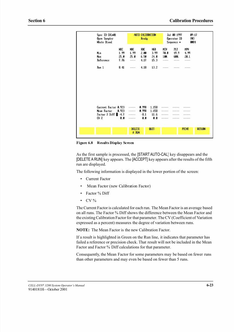
8/21/2019 Equ22-14 CellDyn3200 Op Man
http://slidepdf.com/reader/full/equ22-14-celldyn3200-op-man 327/690
CELL-DYN ® 3200 System Operator’s Manual 6-23
9140181H—October 2001
Section 6 Calibration Procedures
Figure 6.8 Results Display Screen
As the first sample is processed, the [START AUTO-CAL] key disappears and the
[DELETE A RUN] key appears. The [ACCEPT] key appears after the results of the fifth
run are displayed.
The following information is displayed in the lower portion of the screen:
• Current Factor
• Mean Factor (new Calibration Factor)
• Factor % Diff
• CV %
The Current Factor is calculated for each run. The Mean Factor is an average based
on all runs. The Factor % Diff shows the difference between the Mean Factor and
the existing Calibration Factor for that parameter. The CV (Coefficient of Variation
expressed as a percent) measures the degree of variation between runs.
NOTE: The Mean Factor is the new Calibration Factor.
If a result is highlighted in Green on the Run line, it indicates that parameter has
failed a reference or precision check. That result will not be included in the Mean
Factor and Factor % Diff calculations for that parameter.
Consequently, the Mean Factor for some parameters may be based on fewer runs
than other parameters and may even be based on fewer than 5 runs.
8/21/2019 Equ22-14 CellDyn3200 Op Man
http://slidepdf.com/reader/full/equ22-14-celldyn3200-op-man 328/690
6-24 CELL-DYN ® 3200 System Operator’s Manual
9140181H—October 2001
Calibration Procedures
Auto-Cal Method Section 6
For example:
a. Five samples have been run and the [ACCEPT] is displayed after the 5th
run
b. The Factor % Diff for WOC is green, indicating it needs to be calibrated
c. The WOC result for Run #4 is highlighted, indicating it failed a referenceor precision check
d. The Mean Factor and Factor % Diff for WOC are based on only 4 runs
because Run #4 failed its internal check
e. If the operator presses the [ACCEPT] and [CONFIRM ACCEPT] keys, a new
calibrator factor will be entered for WOC but the new factor will be based
on 4, not 5, runs.
Delete a Run
If a result for a parameter is outside a predetermined limit, that result is highlighted
and not included in the Mean Factor and Factor % Diff calculations. The operator
has the option of keeping or deleting the entire run. To delete a run, do thefollowing:
1. Press [DELETE A RUN].
2. A prompt will appear at the bottom of the screen. Type in the number of the
run to be deleted and press the Enter key.
NOTE: Only one run can be deleted in each calibration session. The system
does not allow a deleted run to be replaced with a new run. For
example, if there are 10 runs and the operator deletes Run #5, then
calibration will be based on 9 runs (remember, a highlighted result
on a run will not be included in the Mean Factor or Factor % Diff
for that parameter).
Quit
When [QUIT] is pressed, the [CONFIRM QUIT] and [CANCEL QUIT] keys are displayed.
Pressing [CONFIRM QUIT] deletes all runs and reference values and returns the
operator to the AUTO CALIBRATION screen shown in Figure 6.6. The screen is ready
to receive new reference values. Pressing [CANCEL QUIT] returns the operator to the
current screen.
Accept
This label appears after the results of the fifth run are displayed on the screen,
allowing the operator to accept all the calibration factors shown in the lower
portion of the screen (refer to Figure 6.9). When [ACCEPT] is pressed, two keylabels [CONFIRM ACCEPT] and [CANCEL ACCEPT] are displayed (refer to
Figure 6.10). Pressing [CONFIRM ACCEPT] saves the new calibration factors and
displays the CALIBRATION LOG screen. Pressing [CANCEL ACCEPT] returns the
operator to the Calibration results screen.

8/21/2019 Equ22-14 CellDyn3200 Op Man
http://slidepdf.com/reader/full/equ22-14-celldyn3200-op-man 329/690
CELL-DYN ® 3200 System Operator’s Manual 6-25
9140181H—October 2001
Section 6 Calibration Procedures
Figure 6.9 ACCEPT Key Displayed
Figure 6.10 Confirm Acceptance of New Factors

8/21/2019 Equ22-14 CellDyn3200 Op Man
http://slidepdf.com/reader/full/equ22-14-celldyn3200-op-man 330/690
6-26 CELL-DYN ® 3200 System Operator’s Manual
9140181M—June 2004
Calibration Procedures
Auto-Cal Method Section 6
Auto-Cal Procedure — Open Mode
Displaying the Auto-Cal Screen
1. If necessary, go to the RUN screen and press [CHANGE SAMPLER] to select the
Open Mode.
2. In the MAIN MENU, press [CALIBRATION] to display the main CALIBRATION menu.
3. If necessary, press [OPEN SAMPLER] to display the Open Sampler Calibration
Factors.
NOTE: This key is used to display either the current Open Sampler Factors
or Closed Sampler Factors. It does not change the mode.
4. Press [PRINT] to obtain a printout of the current Open Sampler Calibration Factors.
5. Press [AUTO-CALIBRATE] to display the AUTO-CALIBRATION screen.
Entering Reference Values
1. To enter reference values for each parameter to be calibrated:
a. If calibrator is used, if necessary press [CALIBRATION], enter the
corresponding reference (assay) value from the sheet enclosed with the
calibrator material.
NOTE: For parameters whose assigned value exceeds the Auto-
Calibration pre-set limits, use the manual method for
calibration.
b. If fresh whole blood is used, if necessary press [WHOLE BLOOD], enter the
mean value obtained from the procedure in subsection Fresh Whole
Blood under Determining Reference Values above.
NOTE: Enter the WBC mean as the reference value for both WOC and
NOC.2. Press the Enter key after each entry to save the value and advance the cursor
to the next parameter.
NOTE: To change a value after it was entered, place the cursor on the
appropriate field and enter the correct value. To clear a value, press
[QUIT] followed by [CONFIRM QUIT].
3. When all reference values have been entered, press [START AUTO-CAL] toready the instrument for calibration. The message Ready to aspirate
Cal sample is displayed.
Processing Samples
1. Specimen preparation:
a. If using calibrator material, prepare the calibrator for use according to the
directions given in the package insert. Be certain to carefully read and
follow directions given for warming and mixing.
b. If using fresh whole blood, mix the sample well by inverting the tube at
least ten times. Do not shake the specimen.
2. Place the well-mixed specimen under the Open Mode Sample Probe and
press the Touch Plate. The sample is analyzed and the results are displayed.

8/21/2019 Equ22-14 CellDyn3200 Op Man
http://slidepdf.com/reader/full/equ22-14-celldyn3200-op-man 331/690
CELL-DYN ® 3200 System Operator’s Manual 6-27
9140181M—June 2004
Section 6 Calibration Procedures
3. Repeat steps 1 and 2 above until the desired number of runs for either
Calibrator or Fresh Whole Blood has been completed. Mix the sample well
between each run.
Calibration Check
During the RUN cycle, if a parameter fails the internal reference/precision checksfor calibration, the value for that parameter is backlit in green on the run line,
dashes are displayed in the Current Factor field, and the Mean Factor is not
updated.
Determining Which Parameters Need Calibration
1. After the [ACCEPT] key is displayed, you may continue processing samples
until the desired number of runs has been completed.
2. Observe the Factor % Diff value for each parameter being calibrated:
a. If the value is not highlighted (remains uncolored), that parameter does
not need calibration and the new calibration factor (Mean Factor)
displayed on the screen will not replace the existing calibration factorwhen the [ACCEPT] key is pressed. An uncolored value indicates the
Factor % Diff is less than the value shown in column 2 of Worksheet 3,
Open Mode Calibration Range Criteria, provided in Manual Calibration
Worksheets at the end of this section.
b. If the value is highlighted in green, that parameter needs to be calibrated
and the new calibration factor displayed on the screen will replace the
existing calibration factor when the [ACCEPT] key is pressed. Green
indicates the Factor % Diff is within the range specified in column 3 of
Worksheet 3, Open Mode Calibration Range Criteria, provided in
Manual Calibration Worksheets at the end of this section.
c. If the value is highlighted in purple, it indicates the Factor % Diff isgreater than the value shown in column 4 of Worksheet 3, Open Mode
Calibration Range Criteria, provided in Manual Calibration Worksheets
at the end of this section.
d. If all Factor % Diff values are uncolored, go toCalibration Not Required
below. If at least one Factor % Diff is green, go to Some Parameters
Need Calibration below. If at least one Factor % Diff is purple, go to
subsection Over-Limit Parameters below.
Calibration Not Required
1. If all the Factor % Diff values are uncolored, then calibration is not required
in Open Mode. No update to the Calibration Log is required and no
calibration confirmation is required.
2. If Closed Mode has not been calibrated, go to subsection Auto-Cal — Closed
Mode, otherwise return to the MAIN MENU by pressing [RETURN] followed by
[MAIN].

8/21/2019 Equ22-14 CellDyn3200 Op Man
http://slidepdf.com/reader/full/equ22-14-celldyn3200-op-man 332/690
6-28 CELL-DYN ® 3200 System Operator’s Manual
9140181M—June 2004
Calibration Procedures
Auto-Cal Method Section 6
Some Parameters Need Calibration
1. If at least one Factor % Diff value is green and if no Factor % Diff values are
highlighted in purple, press [ACCEPT] followed by [CONFIRM ACCEPT] tocalibrate the Open Mode. Go to subsection Completing Calibration Log
below.
Over-Limit Parameters
1. If the Factor % Diff for a parameter is highlighted in purple, it indicates there
may be an instrument problem. In this case, do the following:
a. Determine if any component on the instrument was changed. This could
affect calibration. Such components include the Shear Valve, Optical
Flow Cell, Hemoglobin Flow Cell, or one of the syringes.
b. If a component was changed, then treat the result as if it fell within the
“calibration range” (even though it is greater than the upper limit).
CALIBRATION IS REQUIRED for that parameter. Use the arrow keys
to move the cursor to the Factor % Diff value. Press the Enter key to
change the purple to green, indicating calibration is now required.Pressing [ACCEPT] followed by [CONFIRM ACCEPT] will calibrate this
“over limit” parameter along with any other “calibration required”
parameters. Go to subsection Completing Calibration Log below.
NOTE: Because Factor % Diff values highlighted in purple can be
changed to green using the Enter key, it is also possible for the
operator to overwrite these values. However, the change only
appears on the screen; the actual values calculated by the
calibration program remain intact and the Mean Factors are not
affected.
c. If no component was changed and your calculations are correct, DO
NOT CALIBRATE. CONFIRM THAT ALL PRE-CALIBRATIONPROCEDURES WERE COMPLETED AND THEN CALL ABBOTT
DIAGNOSTICS CUSTOMER SERVICE FOR ASSISTANCE
(at 1-877-4ABBOTT in the U.S.). For Customers outside the U.S.
contact your local Customer Service representative.
Completing Calibration Log
1. Complete the Calibration Log (adding comments) as required. If a printout of
the log is desired, press [PRINT LOG].
2. Press [RETURN] to return to the main CALIBRATION screen.
3. Press [PRINT] to obtain a copy of the new Open Sampler Calibration Factors.
Confirming Open Mode Calibration
To confirm calibration in the Open Mode, follow the instructions below. Use the
same Calibrator or Fresh Whole Blood Sample that was used to calibrate the
instrument.
1. In the CALIBRATION menu, press [MAIN] to return to the MAIN MENU.
2. In the MAIN MENU, press [RUN] followed by [SPECIMEN TYPE] and [QCSPECIMEN]. Select an empty QC file.

8/21/2019 Equ22-14 CellDyn3200 Op Man
http://slidepdf.com/reader/full/equ22-14-celldyn3200-op-man 333/690
CELL-DYN ® 3200 System Operator’s Manual 6-29
9140181M—June 2004
Section 6 Calibration Procedures
3. Refer to Worksheet 7, Calibration Confirmation, in Manual Calibration
Worksheets at the end of this section. Make copies of this worksheet as
necessary.
4. Run the same Calibrator or Fresh Whole Blood sample 5 times. After each
run, observe the values displayed on the RUN screen for those parameters that
were calibrated and that now need confirmation. When the runs are complete, print the appropriate QC file and transfer the mean value onto Worksheet #7.
5. Follow the instructions on this worksheet for comparing the mean value
against the reference value.
6. If the difference between the mean and reference (assay) value is within the
stated tolerance limits, then calibration has been confirmed for that
parameter. Go to step 8 below.
NOTE: Calibration of the Open Mode may also be confirmed by running
commercial controls.
7. If a parameter mean is outside the tolerance limits, perform steps 4 and 5
again. If the mean is still outside the tolerance limits, call Abbott Diagnostics
Customer Service for assistance (at 1-877-4ABBOTT in the U.S.).
8. When Open Mode calibration has been confirmed, do one of the following:
a. If Closed Mode has not yet been calibrated, go to subsection Auto-Cal
Procedure — Closed Mode.
b. If Closed Mode calibration has been completed, press [MAIN] to return to
the MAIN MENU.
Auto-Cal Procedure — Closed Mode
NOTE: Auto-Calibration is not available in the Closed Mode on the SL model. To
calibrate Closed Mode, see Calibration Procedure — Mode to Mode in
subsection Enter Factor Method .
Displaying the Auto-Cal Screen
1. If necessary, go to the RUN screen and press [CHANGE SAMPLER] to select the
Closed Mode.
2. In the MAIN MENU, press [CALIBRATION] to display the main CALIBRATION
menu.
3. If necessary, press [CLOSED SAMPLER] to display the Closed Sampler
Calibration Factors.
4. Press [PRINT] to obtain a printout of the current Closed Sampler Calibration
Factors.
5. Press [AUTO-CALIBRATE] to display the AUTO-CALIBRATION screen.
8/21/2019 Equ22-14 CellDyn3200 Op Man
http://slidepdf.com/reader/full/equ22-14-celldyn3200-op-man 334/690
6-30 CELL-DYN ® 3200 System Operator’s Manual
9140181M—June 2004
Calibration Procedures
Auto-Cal Method Section 6
Entering Reference Values
1. Enter reference values for each parameter to be calibrated. If necessary, press
[WHOLE BLOOD], then enter the mean value obtained from the procedure in
subsection Fresh Whole Blood under Determining Reference Values above.
NOTE: Enter the WBC mean as the reference value for both WOC and
NOC.
2. Press the Enter key after each entry to save the value and advance the cursor
to the next parameter.
NOTE: To change a value after it was entered, place the cursor on the
appropriate field and enter the correct value. To clear a value, press
[QUIT] followed by [CONFIRM QUIT].
3. When all reference values have been entered, press [START AUTO-CAL] toready the instrument for calibration.
Processing Samples
1. Mix the fresh whole blood specimen by inverting the sample ten times. Donot shake the specimen. Place the well-mixed specimen in the Tube Retainer,
close the door, and press the Touch Plate. The instrument performs RUN 1
and displays the values in the RUN 1 row.
2. Repeat step 1 above until the desired number of runs has been completed.
Calibration Check
During the RUN cycle, if a parameter fails the internal reference/precision checks
for calibration, the value for that parameter is backlit in green on the run line, dashes
are displayed in the Current Factor field, and the Mean Factor is not updated.
Determining Which Parameters Need Calibration1. After the [ACCEPT] key is displayed, you may continue processing samples
until the desired number of runs has been completed.
2. Observe the Factor % Diff value for each parameter being calibrated:
a. If the value is not highlighted (remains uncolored), that parameter does
not need calibration and the new calibration factor (Mean Factor)
displayed on the screen will not replace the existing calibration factor
when the [ACCEPT] key is pressed. An uncolored value indicates the
Factor % Diff is less than the value shown in column 2 of Worksheet 5,
Mode to Mode Calibration Range Criteria, provided in Manual
Calibration Worksheets at the end of this section.
b. If the value is highlighted in green, that parameter needs to be calibratedand the new calibration factor displayed on the screen will replace the
existing calibration factor when the [ACCEPT] key is pressed. Green
indicates the Factor % Diff is within the range specified in column 3 of
Worksheet 6, Closed Mode Calibration Range Criteria, provided in
Manual Calibration Worksheets at the end of this section.
8/21/2019 Equ22-14 CellDyn3200 Op Man
http://slidepdf.com/reader/full/equ22-14-celldyn3200-op-man 335/690
CELL-DYN ® 3200 System Operator’s Manual 6-31
9140181M—June 2004
Section 6 Calibration Procedures
c. If the value is highlighted in purple, it indicates the Factor % Diff is
greater than the value shown in column 4 of Worksheet 6, Closed Mode
Calibration Range Criteria, provided in Manual Calibration Worksheets
at the end of this section.
d. If all Factor % Diff values are uncolored, go to Calibration Not Required
below. If at least one Factor % Diff is green, go to Some Parameters Need Calibration below. If at least one Factor % Diff is purple, go to
subsection Over-Limit Parameters below.
Calibration Not Required
1. If all the Factor % Diff values are uncolored, then calibration is not required
in Closed Mode. No update to the Calibration Log is required and no
calibration confirmation is required.
2. Return to the MAIN MENU by pressing [RETURN] followed by [MAIN].
Some Parameters Need Calibration
1. If at least one Factor % Diff value is highlighted in green and if no Factor %Diff values are highlighted in purple, press [ACCEPT] followed by [CONFIRM
ACCEPT] to calibrate the Closed Mode. Go to subsection Completing
Calibration Log below.
Over-Limit Parameters
1. If the Factor % Diff for a parameter is highlighted in purple, it indicates there
may be an instrument problem. In this case, do the following:
a. Determine if any component on the instrument was changed. This could
affect calibration. Such components include the Shear Valve, Optical
Flow Cell, Hemoglobin Flow Cell, or one of the syringes.
b. If a component was changed, then treat the result as if it fell within the“calibration range” (even though it is greater than the upper limit).
CALIBRATION IS REQUIRED for that parameter. Use the arrow keys
to move the cursor to the Factor % Diff value. Press the Enter key to
change the purple to green, indicating calibration is now required. Press
[ACCEPT] followed by [CONFIRM ACCEPT] to calibrate this “over limit”
parameter along with any other “calibration required” parameters. Go to
subsection Completing Calibration Log below.
NOTE: Because Factor % Diff values highlighted in purple can be changed
to green using the Enter key, it is also possible for the operator to
overwrite these values. However, the change only appears on the
screen; the actual values calculated by the calibration program
remain intact and the Mean Factors are not affected.
c. If no component was changed and your calculations are correct, DO
NOT CALIBRATE. CONFIRM THAT ALL PRE-CALIBRATION
PROCEDURES WERE COMPLETED AND THEN CALL ABBOTT
DIAGNOSTICS CUSTOMER SERVICE FOR ASSISTANCE
(at 1-877-4ABBOTT in the U.S.).

8/21/2019 Equ22-14 CellDyn3200 Op Man
http://slidepdf.com/reader/full/equ22-14-celldyn3200-op-man 336/690
6-32 CELL-DYN ® 3200 System Operator’s Manual
9140181M—June 2004
Calibration Procedures
Auto-Cal Method Section 6
Completing Calibration Log
1. Complete the Calibration Log (adding comments) as required. If a printout of
the log is desired, press [PRINT LOG].
2. Press [RETURN] to return to the main CALIBRATION screen.
3. Press [PRINT] to obtain a copy of the new Closed Sampler Calibration Factors.
Confirming Closed Mode Calibration
To confirm calibration in the Closed Mode, follow the instructions below. Use the
same Fresh Whole Blood Sample that was used to calibrate the instrument.
1. In the CALIBRATION menu, press [MAIN] to return to the MAIN MENU.
2. In the MAIN MENU, press [RUN] followed by [SPECIMEN TYPE]. Select an
empty QC file and press [QC SPECIMEN].
3. Refer to Worksheet 7, Calibration Confirmation, in Manual Calibration
Worksheets at the end of this section. Make copies of this worksheet as
necessary.
4. Run the same Fresh Whole Blood samples in duplicate.
NOTE: You may also elect to Run Commercial Control as a means of
confirming calibration.
5. After each run, observe the values displayed on the RUN screen for those
parameters that were calibrated and that now need confirmation. Write these
values in the appropriate space on Worksheet 7.
6. Follow the instructions on this worksheet for calculating a mean and
comparing the mean value against the reference value.
7. If the difference between the mean and reference value is within the stated
tolerance limits, then calibration has been confirmed for that parameter. Go
to step 9 below.
8. If a parameter mean is outside the tolerance limits, perform steps 4 and 5
again. If the mean is still outside the tolerance limits, call Abbott Diagnostics
Customer Service for assistance (at 1-877-4ABBOTT in the U.S.).
9. When Closed Mode calibration has been confirmed, press [MAIN] to return to
the MAIN MENU.

8/21/2019 Equ22-14 CellDyn3200 Op Man
http://slidepdf.com/reader/full/equ22-14-celldyn3200-op-man 337/690
CELL-DYN ® 3200 System Operator’s Manual 6-33
9140181H—October 2001
Section 6 Calibration Procedures
Enter Factor Method
OverviewThe Enter Factor Calibration Method is used to enter a predetermined factor to
adjust calibration when a consistent bias exists between the CELL-DYN 3200
System and a comparison analyzer. This method can also be used when calibrating
the secondary mode of the system to the primary mode.
Either Calibrator or Fresh Whole Blood can be used for calibration.
Fresh Whole Blood: Because the same samples will be used to first obtain
reference values on a reference instrument then to calibrate in the Open and Closed
Modes, it is important to begin with a sufficient amount of sample (12 mL each is
recommended).
A set of worksheets is provided in Manual Calibration Worksheets at the end of
this section to assist in the calibration process.
NOTE: Always complete the Pre-Calibration procedures before beginning any
calibration.
Enter Calibration Factor Screen
When the Enter Factor key is pressed in the main CALIBRATION menu, the ENTERCALIBRATION FACTOR menu is displayed (refer to Figure 6.11). New calibration
factors are manually entered on this screen.
The following soft key labels are displayed:
RESTORE FACTORS
RESET ALL TO 1.000
RETURN

8/21/2019 Equ22-14 CellDyn3200 Op Man
http://slidepdf.com/reader/full/equ22-14-celldyn3200-op-man 338/690
6-34 CELL-DYN ® 3200 System Operator’s Manual
9140181H—October 2001
Calibration Procedures
Enter Factor Method Section 6
Figure 6.11 Enter Factor Screen
General Information
Calibrator
The requirements for using Calibrator in the Enter Factor method are similar to the
Auto-Cal method. Refer to Calibrator Requirements under Calibration Materials
earlier in this section.
Fresh Whole Blood
In addition to the requirements listed in Fresh Whole Blood Requirements under
Calibration Materials earlier in this section, the following procedures apply when
using the Enter Factor method:
1. A minimum of five samples are required for adequate calibration.
2. Mean values should be calculated for each parameter based on 10 runs (five
samples, each run twice into one QC file). These mean parameter values can
then be entered as reference values on the CELL-DYN 3200 System.
ICSH Recommendations
When using fresh whole blood samples, reference values should be determined
according to the following ICSH recommendations.

8/21/2019 Equ22-14 CellDyn3200 Op Man
http://slidepdf.com/reader/full/equ22-14-celldyn3200-op-man 339/690
CELL-DYN ® 3200 System Operator’s Manual 6-35
9140181H—October 2001
Section 6 Calibration Procedures
WOC, NOC, RBC, and PLT
Reference values for white blood cells, red blood cells, and platelets may be
determined using multiple counts from a certified hemocytometer, from a counter
that meters a fixed, calibrated sample volume, or from a reliably calibrated
hematology analyzer.
HGB
Reference values for hemoglobin may be determined using either the reference
cyanmethemoglobin method or a reliably calibrated hemoglobinometer or
hematology analyzer.
NOTE: DO NOT attempt to calibrate the CELL-DYN 3200 System with a
hemoglobin standard designed for the calibration of specific reference
cyanmethemoglobin methods. The instrument uses a modified
hemoglobinhydroxyalamine method which is not designed to analyze
these standards directly.
MCVReference values for the mean cell volume may be determined by calculation from
the reference microhematocrit and RBC measurements or from multiple analyses
on a reliably calibrated hematology analyzer.
NOTE: Reference microhematocrit values may be determined by multiple
analyses using the NCCLS method for Packed Cell Volume (PCV).2 Use
only plain (non-anticoagulated) capillary tubes. Be certain to verify the
proper operation of the microhematocrit centrifuge and the timer as
recommended by NCCLS.
Determining Reference Values — Fresh Whole Blood
Follow the procedures below to determine the reference values that will be used to
calibrate the instrument using fresh whole blood.
NOTE: No more than two hours should elapse between determining the
Reference Mean Values and performing the calibration.
WARNING: Potential Biohazard. Consider all specimens potentially
infectious. Wear gloves, lab coats, and safety glasses and follow other
biosafety procedures as specified in the OSHA Bloodborne Pathogen Rule
(29 CFR 1910.1030) or other equivalent biosafety procedures.
1. Go to a reference hematology instrument (or use appropriate hematology
methods) with 5 samples of normal, fresh whole blood. Run each sample atleast twice for a minimum of 10 replicates on the reference instrument.
NOTE: Because the same samples will be used to first obtain reference
values on a reference instrument then to calibrate in the Open and
Closed Modes, it is important to begin with a sufficient amount of
each sample.

8/21/2019 Equ22-14 CellDyn3200 Op Man
http://slidepdf.com/reader/full/equ22-14-celldyn3200-op-man 340/690
6-36 CELL-DYN ® 3200 System Operator’s Manual
9140181H—October 2001
Calibration Procedures
Enter Factor Method Section 6
2. If a mean value for each parameter based on at least 10 runs is not
automatically calculated by the reference hematology instrument or
hematology methods, use a calculator to determine the cumulative Reference
Mean for each parameter. For example:
The cumulative Reference WOC Mean is 7.15 when the WOC results from
each run are as follows:
• Sample 1 = 9.2, 9.1
• Sample 2 = 4.5, 4.6
• Sample 3 = 6.1, 5.9
• Sample 4 = 7.0, 7.3
• Sample 5 = 8.9, 8.9
The cumulative mean of 7.15 equals the sum of the values (71.5) divided by the 10
runs.
You may use the worksheet on the following page to record the values obtained
from running samples on a reference instrument. Make copies of the blank
worksheet as necessary.
NOTE: Enter the WBC mean as the reference value for both the WOC and NOC.

8/21/2019 Equ22-14 CellDyn3200 Op Man
http://slidepdf.com/reader/full/equ22-14-celldyn3200-op-man 341/690
CELL-DYN ® 3200 System Operator’s Manual 6-37
9140181M—June 2004
Section 6 Calibration Procedures
Whole Blood Calibration Reference Values Worksheet
Date: Technologist:
NOTE: The WBC value obtained on the Reference Instrument should be used for
calibrating both the WOC and NOC parameters on the CELL-DYN 3200
Instrument.
Calibration Procedure — Open Mode
Follow the procedure below for calibrating the instrument in the Open Mode.
Determining New Calibration Factors
1. If necessary, go to the RUN menu and press [CHANGE SAMPLER] to select the
Open Mode.
2. In the MAIN MENU, press [CALIBRATION] to display the main CALIBRATION menu.
Sample ID Run #WBC
(WOC)
WBC
(NOC)
RBC HGB MCV PLT
1
2
1
2
1
2
1
2
1
2
Cumulative Mean
8/21/2019 Equ22-14 CellDyn3200 Op Man
http://slidepdf.com/reader/full/equ22-14-celldyn3200-op-man 342/690
6-38 CELL-DYN ® 3200 System Operator’s Manual
9140181H—October 2001
Calibration Procedures
Enter Factor Method Section 6
3. Obtain a printout of the current Open Sampler Calibration Factors as follows:
a. If necessary, press [OPEN SAMPLER] to display the Open Sampler
Calibration Factors.
b. Press [PRINT] to obtain a printout of these factors. Save this printout. It
will be used when completing Worksheet 1 at the end of this section.
4. Open an empty QC file as follows:
a. In the MAIN MENU, press [RUN] to display the RUN menu.
b. If necessary, press [CHANGE SAMPLER] to select Open Mode.
c. Press [SPECIMEN TYPE] to display the SPECIMEN TYPE menu.
d. Use the arrow keys on the keyboard to move the cursor to an empty QC
file and type the desired file name in the <File Name> field.
e. Press Enter to save the name. Use the Up Arrow key to move the cursor
back to the file name.
f. Press [QC SPECIMEN] to return to the RUN screen.
5. If calibrator material is used, follow the mixing instructions found in the
package insert. If fresh whole blood is used, mix it well by inverting the tube
at least ten times. Do not shake the specimen.
WARNING: Potential Biohazard. Consider all specimens, calibrators,
and controls that contain human blood as potentially infectious. Wear
gloves, lab coats, and safety glasses and follow other biosafety procedures
as specified in the OSHA Bloodborne Pathogen Rule (29 CFR 1910.1030)
or other equivalent biosafety procedures.
6a. If calibrator material is used, whenREADY appears in the Status Box, place
the calibrator under the Open Mode Sample Probe and press the Touch Plate
to run the specimen. The results of the run are placed in the QC file selected
in step 1. Repeat this step until the minimum number of recommended runs(6) is completed. Go to step 7.
6b. If fresh whole blood is used, when READY appears in the Status Box place
the sample under the Open Mode Sample Probe and press the Touch Plate to
run the specimen. The results of the run are placed in the QC file selected in
step 1. Repeat this process until 10 runs (2 from each sample) are completed.
7. When sample processing is completed, press [MAIN] followed by [QUALITYCONTROL]. Use the arrow keys to place the cursor on the appropriate QC file
and press [VIEW QC LOG].
8. Press [PRINT QC LOG] to print the Summary Report for the selected QC file.

8/21/2019 Equ22-14 CellDyn3200 Op Man
http://slidepdf.com/reader/full/equ22-14-celldyn3200-op-man 343/690
CELL-DYN ® 3200 System Operator’s Manual 6-39
9140181H—October 2001
Section 6 Calibration Procedures
9. To determine the New Calibration Factor for each parameter:
a. For Calibrator, use the values on the assay sheet and the CELL-DYN
mean values determined in steps 2 through 8 above. Enter this
information in columns 1 and 2 respectively of Worksheet 1, Open Mode
Calibration — New Factors, provided in Manual Calibration
Worksheets at the end of this section. b. For Fresh Whole Blood, use the Reference Mean Values determined in
Determining Reference Values — Fresh Whole Blood described earlier
(refer to the Whole Blood Calibration Reference Values Worksheet) and
the CELL-DYN Mean values determined in steps 2 through 8 above.
Enter this information in columns 1 and 2 respectively of Worksheet 1,
Open Mode Calibration — New Factors, provided in Manual
Calibration Worksheets at the end of this section.
c. Enter the current Open Sampler Calibration Factors, obtained in step 3
above, in column 3 of Worksheet 1.
NOTE: Be sure to make copies of this worksheet as needed.
10. Follow the instructions on Worksheet 1 to calculate the new Open Mode
Calibration Factor for each parameter and enter this information in column 4
of the worksheet. The method for determining the new factors is:
a. Calibrator Calibration:
b. Whole Blood Calibration:
For example, if the Reference Mean Value for WOC is 6.6, the CELL-DYN
Mean for WOC is 7.1, and the current Open Mode Calibration Factor for
WOC is 0.98, then:
(6.6 / 7.1) × 0.98 = 0.91
and 0.91 is your New Open Mode Calibration Factor for WOC.
Determining Which Parameters Need Calibration
To determine which parameters require calibration in the Open Mode, follow the
procedure below:
1a. Transfer the values from column 4 of Worksheet 1 to the new Open Mode
Factor columns 1 and 3 of Worksheet 2, Open Mode Factor % Difference,
provided in Manual Calibration Worksheets at the end of this section.
NOTE: Make copies of this worksheet as needed.
1b. Transfer the values for the Current Open Mode Cal factor from column 3 of
Worksheet 1 and enter these values in column 2 of Worksheet 2.
2. Follow the instructions on this worksheet to determine the Factor % Diff for
each parameter.
Assay Value
CELL-DYN Mean--------------------------------------------- Current Open Mode
Calibration Factor × New Open Mode
Calibration Factor =
Reference Mean
CELL-DYN Mean--------------------------------------------- Current Open Mode
Calibration Factor × New Open Mode
Calibration Factor =
8/21/2019 Equ22-14 CellDyn3200 Op Man
http://slidepdf.com/reader/full/equ22-14-celldyn3200-op-man 344/690
6-40 CELL-DYN ® 3200 System Operator’s Manual
9140181L—July 2003
Calibration Procedures
Enter Factor Method Section 6
3. Transfer the Factor % Diff values from column 5 (calculated in Worksheet 2)
to column 1 of Worksheet 3, Open Mode Calibration Range Criteria,
provided in Manual Calibration Worksheets at the end of this section.
NOTE: Make copies of this worksheet as needed.
4. For each parameter, if the Factor % Diff is equal to or less than the value in
the Lower Limit column, then CALIBRATION IS NOT REQUIRED for that
parameter because the value is within range.
5. For each parameter, if the Factor % Diff falls between the upper and lower
calibration range, shown in the Calibration Range column, then
CALIBRATION IS REQUIRED.
6. For each parameter, if the Factor % Diff is greater than the value in the
Upper Limit column, there may be a computation error or an instrument
problem. In this case, do the following:
a. Recheck all numbers and calculations on Worksheets 1 and 2.
b. Determine if any component on the instrument was changed. This could
affect calibration. Such components include the Shear Valve, OpticalFlow Cell, Hemoglobin Flow Cell, or one of the syringes.
c. If a component was changed, then treat the result as if it fell within the
“calibration range” (even though it is greater than the upper limit).
CALIBRATION IS REQUIRED for that parameter.
d. If no component was changed and your calculations are correct, DO
NOT CALIBRATE. Confirm that all Pre-Calibration procedures were
completed and call Abbott Customer Service for assistance
(at 1-877-4ABBOTT in the U.S.).
7. Based on the results from steps 1 through 6 above, do one of the following:
a. If any parameter needs to be calibrated in the Open Mode, go to Entering
New Calibration Factors — Open Mode. b. If none of the parameters requires Open Mode calibration and Closed
Mode has not been calibrated, go to Calibration Procedure — Mode to
Mode to determine if Closed Mode needs calibrating.
c. If none of the parameters requires Open Mode calibration and Closed
Mode calibration has already been completed, press [MAIN] to return to
the MAIN MENU.

8/21/2019 Equ22-14 CellDyn3200 Op Man
http://slidepdf.com/reader/full/equ22-14-celldyn3200-op-man 345/690
CELL-DYN ® 3200 System Operator’s Manual 6-41
9140181H—October 2001
Section 6 Calibration Procedures
Entering New Calibration Factors — Open Mode
1. In the main CALIBRATION menu, press [ENTER FACTOR].
2. Use the arrow keys to select the first factor in the Open Sampler column to
be changed. Type in the New Calibration Factor calculated in step 10 in
Determining New Calibration Factors above. Press the Enter key to save the
factor and advance the cursor. If necessary, use the arrow keys to select the
next factor to be changed.
NOTE: Prior to exiting the screen, the operator may press the [RESTOREFACTORS] soft key to recall factors, stored on the Hard Disk,
corresponding to the current mode — Open or Closed. [RESET ALLTO 1.000] is used to reset all factors displayed on the screen to
1.000.
3. When all new factors have been entered, press [RETURN] to display the
CALIBRATION LOG screen with the new calibration factors.
NOTE: If no changes are made in the ENTER CALIBRATION FACTOR screen,
pressing [RETURN] will bypass the CALIBRATION LOG screen and
display the main CALIBRATION menu.
4. Complete the Calibration Log (adding comments) as required. If a printout of
the log is desired, press [PRINT LOG].
5. Press [RETURN] twice to return to the main CALIBRATION menu.
6. Press [PRINT] to obtain a copy of the new Open Sampler Calibration Factors.
7. Press [MAIN] to return to the MAIN MENU.

8/21/2019 Equ22-14 CellDyn3200 Op Man
http://slidepdf.com/reader/full/equ22-14-celldyn3200-op-man 346/690
6-42 CELL-DYN ® 3200 System Operator’s Manual
9140181M—June 2004
Calibration Procedures
Enter Factor Method Section 6
Confirming Open Mode Calibration
1. Press [RUN] followed by [SPECIMEN TYPE]. Select an empty QC file and press
[QC SPECIMEN].
2. Refer to Worksheet 7, Calibration Confirmation, in Manual Calibration
Worksheets provided at the end of this section.NOTE: Make copies of this worksheet as necessary.
3a. Obtain the calibrator used in the calibration process and run it three times into
the empty QC file. When the runs are completed, print the appropriate QC
file and transfer the mean values to the appropriate spaces on Worksheet 7.
3b. Obtain each of the five samples used in the calibration process and run each
sample once. When the five runs are complete, print the appropriate QC file
and transfer the mean values to the appropriate spaces on Worksheet 7.
4. Follow the instructions on the worksheet for comparing the mean value
against the assay values (calibrator), or reference mean (fresh whole blood).
5. If the difference between the mean of 3/5 runs and the assay value/reference
mean is within the tolerance limits, then calibration is confirmed for that
parameter. Proceed to calibrate the Closed Mode if not already calibrated.
NOTE: Calibration of the Open Mode may also be confirmed by running
commercial controls.
6. If a parameter’s mean is outside the stated tolerance limits, repeat steps 3 and
4 above for that parameter. If the mean is still outside the stated tolerance
limits, call Abbott Diagnostics Customer Service for assistance
(at 1-877-4ABBOTT in the U.S.).

8/21/2019 Equ22-14 CellDyn3200 Op Man
http://slidepdf.com/reader/full/equ22-14-celldyn3200-op-man 347/690
CELL-DYN ® 3200 System Operator’s Manual 6-43
9140181M—June 2004
Section 6 Calibration Procedures
Calibration Procedure — Mode to Mode
After the Open Mode has been calibrated, or Open Mode calibration is confirmed,
fresh normal whole blood specimens are used to calibrate the Closed Mode. The
same specimens are run into quality control files in the Open and Closed Modes.
The automatically calculated parameter means from each mode are used to
manually compute the calibration bias and the new calibration factors. The new
Closed Mode Calibration Factors are then entered manually on the ENTER FACTOR
screen in the CALIBRATION Menu.
NOTE: Whole blood specimens should meet the requirements outlined earlier in
this Section in Subsection: Calibration Materials.
NOTE: Specimens should be run the same number of times in each mode.
Determining the Closed Mode Mean
1. If necessary, go to the RUN menu and press [CHANGE SAMPLER] to select the
Closed Mode.
2. In the MAIN MENU, press [CALIBRATION] to display the main CALIBRATION menu.
3. Obtain a printout of the current Closed Sampler Calibration Factors as
follows:
a. If necessary, press [CLOSED SAMPLER] to display the Closed Sampler
Calibration Factors.
b. Press [PRINT] to obtain a printout of these factors. Save this printout. It
will be used when completing Worksheet 6 at the end of this section.
4. Open an empty QC file as follows:
a. In the MAIN MENU, press [RUN] to display the RUN menu.
b. If necessary, press [CHANGE SAMPLER] to select Closed Mode.c. Press [SPECIMEN TYPE] to display the SPECIMEN TYPE menu.
d. Use the arrow keys on the keyboard to move the cursor to an empty QC
file and type the desired name in the <File Name> field.
e. Press Enter to save the name. Use the Up Arrow key to move the cursor
back to the file name.
f. Press [QC SPECIMEN] to return to the RUN screen.
WARNING: Potential Biohazard. Consider all specimens, calibrators,
and controls that contain human blood as potentially infectious. Wear
gloves, lab coats, and safety glasses and follow other biosafety procedures
as specified in the OSHA Bloodborne Pathogen Rule (29 CFR 1910.1030)
or other equivalent biosafety procedures.
5. Calibrating the CS model (Fresh Whole Blood):
a. There should be a minimum of 5 Fresh Whole Blood Specimens. Mix the
specimens well by inverting the tubes at least ten times. Do not shake the
specimens.
b. Place a well-mixed specimen in the Tube Retainer, close the door, and
press the Touch Plate.

8/21/2019 Equ22-14 CellDyn3200 Op Man
http://slidepdf.com/reader/full/equ22-14-celldyn3200-op-man 348/690
6-44 CELL-DYN ® 3200 System Operator’s Manual
9140181M—June 2004
Calibration Procedures
Enter Factor Method Section 6
c. Run each specimen in duplicate until a minimum of 10 runs has been
completed.
d. Go to step 7.
6. Calibrating the SL model with Fresh Whole Blood:
a. Mix the fresh whole blood specimens well by inverting each specimen
10 times. Do not shake the specimen.
b. Aliquot the sample as follows:
There should be a minimum of 5 specimens (refer to Number of Cycles
under Calibration Materials earlier in this section). Aliquot the first
specimen in equal volumes into two tubes. Aliquot the second specimen
in equal volumes into another two tubes. Repeat this procedure until all
5 specimens have been aliquoted (for a total of 10 tubes).
c. Place the closed tubes on a rack and set the rack on the “load” side.
d. Press [START LOADER]. Allow the instrument to process all the
specimens.
7. When processing is completed, press [MAIN] followed by [QUALITYCONTROL]. Use the arrow keys to place the cursor on the appropriate QC file
and press [VIEW QC LOG].
8. Press [PRINT QC LOG] to print the Summary Report for the selected QC file.
9. To determine the Mode to Mode Calibration Difference for each parameter:
a. Transfer the information from Step 8 above to the Manual Mode to Mode
Calibration Worksheet and enter it in the first column. (Worksheet 4)
b. Determine the Open Mode Mean for the Fresh Whole Blood samples as
described in the Calibration Procedure - Open Mode, Determining New
Calibration Factors, steps 2–8. Transfer the information to the Manual
Mode to Mode Calibration worksheet and enter it in columns 2 and 3.
c. Calculate the Mode to Mode Calibration Difference for each parameter
as follows:
NOTE: Make copies of this worksheet as needed.
10. Enter the Mode to Mode Calibrator Difference for each parameter in
column 4 of the worksheet.
Closed Mode Mean - Open Mode Mean
Open Mode Meanx 100 = % Difference

8/21/2019 Equ22-14 CellDyn3200 Op Man
http://slidepdf.com/reader/full/equ22-14-celldyn3200-op-man 349/690
CELL-DYN ® 3200 System Operator’s Manual 6-45
9140181M—June 2004
Section 6 Calibration Procedures
Determining Which Parameters Need Calibration
To determine which parameters require calibration in the Closed Mode, follow the
procedure below:
1. Obtain the values derived in column 4 of Worksheet 4 and enter these values
in column 1 of Worksheet 5, Mode to Mode Calibration Criteria, provided in
subsection Manual Calibration Worksheets at the end of this section.
NOTE: Make copies of this worksheet as needed.
2. Follow the instructions on Worksheet 5 to determine which parameters
require calibration.
NOTE: Make copies of this worksheet as needed.
3. For each parameter, if the % Diff is equal to or less than the value in the
Lower Limit column, then CALIBRATION IS NOT REQUIRED for that
parameter because the value is within range. If none of the parameters
requires Closed Mode calibration and Open Mode calibration has already
been completed, press [MAIN] to return to the MAIN MENU.
4. For each parameter, if the % Diff falls between the upper and lower
calibration range, shown in the Calibration Range column, then
CALIBRATION IS REQUIRED.
5. For each parameter, if the % Diff is greater than the value in the Upper Limit
column, there may be a computation error or an instrument problem. In this
case, do the following:
a. Recheck all numbers and calculations on Worksheets 4 and 5.
b. Determine if any component on the instrument was changed. This could
affect calibration. Such components include the Shear Valve, Optical
Flow Cell, Hemoglobin Flow Cell, or one of the syringes.
c. If a component was changed, then treat the result as if it fell within the“calibration range” (even though it is greater than the upper limit).
CALIBRATION IS REQUIRED for that parameter.
d. If no component was changed and your calculations are correct, DO
NOT CALIBRATE. Confirm that all Pre-Calibration procedures were
completed and call Abbott Diagnostics Customer Service for assistance
(at 1-877-4ABBOTT in the U.S.).

8/21/2019 Equ22-14 CellDyn3200 Op Man
http://slidepdf.com/reader/full/equ22-14-celldyn3200-op-man 350/690
6-46 CELL-DYN ® 3200 System Operator’s Manual
9140181M—June 2004
Calibration Procedures
Enter Factor Method Section 6
Calculating New Closed Mode Calibration Factors
Based on the results from steps 1 through 5 above, perform the following:
1. If Closed Mode calibration is required, use Worksheet 6 to calculate the New
Closed Mode Calibration Factor for the parameters that require calibration.
(Use the Current Closed Mode Cal Factor that was printed in Determining
the Closed Mode Mean, step 3, at the start of this procedure.)
Whole Blood Calibration:
For example, if the Open Mode Mean Value for WOC is 6.6, the Closed
Mode Mean for WOC is 7.4, and the current Closed Mode Calibration Factor
for WOC is 1.04, then:
(6.6 / 7.4) × 1.04 = 0.93
and 0.93 is the New Closed Mode Calibration Factor for WOC.
2a. If the new Closed Mode Calibration Factors falls within the acceptable range
given on the worksheet, follow the procedure for entering new calibration
factors below.
2b. If the New Closed Mode Calibration Factor for a given parameter falls
outside the acceptable range, there may be a computation error. Do not
calibrate that parameter. Recheck all calculations. If the factor(s) is still
outside the acceptable range, call Abbott Diagnostics Customer Service for
assistance (at 1-877-4ABBOTT in the U.S.).
Open Mode Mean
Closed Mode Mean----------------------------------------------- Current Closed Mode
Calibration Factor × New Closed Mode
Calibration Factor =

8/21/2019 Equ22-14 CellDyn3200 Op Man
http://slidepdf.com/reader/full/equ22-14-celldyn3200-op-man 351/690
CELL-DYN ® 3200 System Operator’s Manual 6-47
9140181H—October 2001
Section 6 Calibration Procedures
Entering New Calibration Factors — Closed Mode
1. In the CALIBRATION menu, press [ENTER FACTOR].
2. Use the arrow keys to select the first factor in the Closed Sampler column to
be changed. Type in the New Calibration Factor calculated in Calculating
New Closed Mode Calibration Factors above. Press the Enter key to save the
factor and advance the cursor. If necessary, use the arrow keys to select the
next factor to be changed.
NOTE: Prior to exiting the screen, the operator may press the [RESTOREFACTORS] soft key to recall factors, stored on the Hard Disk,
corresponding to the current mode — Open or Closed. [RESET ALLTO 1.000] is used to reset all factors displayed on the screen to
1.000.
3. When all new factors have been entered, press [RETURN] to display the
CALIBRATION LOG screen with the new calibration factors.
NOTE: If no changes are made in the ENTER CALIBRATION FACTOR screen,
pressing [RETURN] will bypass the CALIBRATION LOG screen and
display the main C ALIBRATION menu.
4. Complete the Calibration Log (adding comments) as required. If a printout of
the log is desired, press [PRINT LOG].
5. Press [RETURN] twice to return to the main CALIBRATION menu.
6. Press [PRINT] to obtain a copy of the new Closed Sampler Calibration Factors.
7. Press [MAIN] to return to the MAIN MENU.

8/21/2019 Equ22-14 CellDyn3200 Op Man
http://slidepdf.com/reader/full/equ22-14-celldyn3200-op-man 352/690
6-48 CELL-DYN ® 3200 System Operator’s Manual
9140181M—June 2004
Calibration Procedures
Enter Factor Method Section 6
Confirming Closed Mode Calibration
1. Press [RUN] followed by [SPECIMEN TYPE]. Select an empty QC file and press
[QC SPECIMEN].
2. Refer to Worksheet 7, Calibration Confirmation, in subsection Manual
Calibration Worksheets. Make copies of this worksheet as necessary.3. Take each of the five samples used in the calibration process and run each
sample once. When done, print the appropriate QC file and transfer the values
in the appropriate space on the Worksheet 7.
NOTE: Closed Mode Calibration may also be confirmed by running
commercial controls.
4. Follow the instructions on the worksheet for comparing the mean value
against the reference mean (fresh whole blood).
5. If the difference between the mean and reference mean is within the stated
tolerance limits, then calibration has been confirmed for that parameter.
6. If a parameter’s mean is outside the stated tolerance limits, repeat steps 3 and
4 above for that parameter. If the mean is still outside the stated tolerance
limits, call Abbott Diagnostics Customer Service for assistance
(at 1-877-4ABBOTT in the U.S.).

8/21/2019 Equ22-14 CellDyn3200 Op Man
http://slidepdf.com/reader/full/equ22-14-celldyn3200-op-man 353/690
CELL-DYN ® 3200 System Operator’s Manual 6-49
9140181M—June 2004
Section 6 Calibration Procedures
Post Calibration Procedure
Quality ControlConfirm calibration changes by running all levels of controls into the appropriate
QC files. If any parameters fall outside the limits, proceed as follows:
1. Obtain new vials of the controls.
2. Warm and mix them properly and again run them into the appropriate QC
files.
If parameters still exceed the limits, proceed as follows:
1. Collect all the calibration documentation including the Pre-Calibration
worksheets. (Be certain you have recorded lot numbers where indicated.)
2. Call Abbott Diagnostics Customer Service for assistance
(at 1-877-4ABBOTT in the U.S.).
NOTE: Inform the Customer Support Specialist if a reagent and/or lot
number of reagent was changed just prior to the calibration
procedure.
3. Include documentation as to the resolution of the problem in the instrument
logbook.
Calibration Backup
The current calibration factors should be saved on the CELL-DYN 3200 Set-Up
Disk #1whenever calibration is changed. Data should also be saved whenever any
Set-Up information is changed and after any service work is performed. The back-up procedure copies the following Set-Up information from the Data Module to
Set-Up Disk #1:
• Calibration Factors
• Retic QC
• Patient Limits
• Analyzer Module Set Points (e.g., gains, dilution factors [internal calibration
factors], thresholds, pressure/vacuum settings)
• Units Selection
To back-up the calibration factors, proceed as follows:
1. With the MAIN MENU screen displayed, press the F12 key, then the F8 key.
The following message displays:
CD3200 program terminated (0)
CD3200 program terminated (0)
C:\CD3200>

8/21/2019 Equ22-14 CellDyn3200 Op Man
http://slidepdf.com/reader/full/equ22-14-celldyn3200-op-man 354/690
6-50 CELL-DYN ® 3200 System Operator’s Manual
9140181L—July 2003
Calibration Procedures
Post Calibration Procedure Section 6
2. Obtain SET-UP Disk#1 from the Disk Storage Container located on the back
of the instrument, and insert the disk into the instrument’s floppy disk drive
(located on the right-side panel of the instrument). Press and hold the [CTRL] and [ALT] keys, then press the [DELETE] key on the keyboard, this causes the
data station to boot the floppy disk.
3. When the DOS prompt displays:Select (A) Abort; (S) Save; (R) Restore: [A, S, R]?
type “s” (Save). The following files are saved:
Nonvol (NONVOL)
Calibration Log (CALLOG)
Worklist Log (WKLOG)
Error Log (ERRORLOG)
Retic QC (RQCLOG)
NOTE:The (R) Restore option copies existing setup information from the
SET-UP Disk to the Data Station hard disk. Selecting “r” will
overwrite the current calibration and instrument setting files in the
CELL-DYN 3200 directory with previously-saved versions from
the archive on the floppy disk. In this case, the instrument may need
to be recalibrated and instrument settings may need to be
re-established by a field service representative.
This option is used when a hardware or software failure occurs and
should only be used at the direction of Abbott Customer Service.
NOTE: In the message “Write Protect Error Writing Drive A” displays,
eject the SET-UP Disk. Unlock the disk by sliding the write-
protected tab on the disk’s corner. Reinsert the disk and press the“R ” (Retry) key on the keyboard.
4. When the following prompt displays, the backup is complete:
A:/
5. Remove SET-UP Disk #1 from the diskette drive and return it to the Disk
Storage Container located on the back of the instrument.
6. Turn the instrument power OFF then ON.
7. When the instrument is initialized, press the [RUN] key to prime the system.

8/21/2019 Equ22-14 CellDyn3200 Op Man
http://slidepdf.com/reader/full/equ22-14-celldyn3200-op-man 355/690
CELL-DYN ® 3200 System Operator’s Manual 6-51
9140181H—October 2001
Section 6 Calibration Procedures
Manual Calibration Worksheets
Seven worksheets are provided to assist in the calculation and determination ofnew calibration factors for the CELL-DYN 3200 System. Three worksheets are
designed for the Open Mode procedure, three worksheets for the Closed Mode
procedure, and one worksheet for confirmation.
• Worksheet 1 Open Mode Calibration — New Factors
• Worksheet 2 Open Mode Factor % Difference
• Worksheet 3 Open Mode Calibration Range Criteria
• Worksheet 4 Mode to Mode Calibration Difference
• Worksheet 5 Mode to Mode Calibration Criteria
• Worksheet 6 New Closed Mode Calibration Factors
• Worksheet 7 Calibration Confirmation — QC Specimen Type
Make copies of these worksheets as necessary.

8/21/2019 Equ22-14 CellDyn3200 Op Man
http://slidepdf.com/reader/full/equ22-14-celldyn3200-op-man 356/690
6-52 CELL-DYN ® 3200 System Operator’s Manual
9140181H—October 2001
Calibration Procedures
Manual Calibration Worksheets Section 6
Worksheet 1
Open Mode Calibration — New Factors
Instrument: Date: Operator:
1. In column 1, enter the calibrator assay values or the fresh whole blood reference means that were used in
the calibration process (refer to step 9 on page 6-45). Use the same WBC Reference Value for WOC and
NOC.
2. In column 2, enter the mean values calculated in the QC file.
3. In column 3, enter the calibration factors that existed prior to running the current calibration procedure.
4. For each parameter, divide the value in column 1 by the value in column 2 and multiply the result by thevalue in column 3.
5. The value calculated in step 4 is the new calibration factor. Write this value in column 4.
6. Compare the new calibration factor in column 4 with the range shown in column 5. If the new factor falls
within the range, go to Worksheet 2. If the new factor falls outside the range, check all calculations. If
necessary, run the samples again into a new QC file and perform new calculations.
(Calculate All Factors To Three Decimal Places)
(1)
Assay Value
or
Ref Mean
/
(2)
Open Mode
Mean
x
(3)
Current
Open Mode
Cal Factor
=
(4)
New
Open Mode
Cal Factor
(5)
Range
WOC / x = 0.700–1.300
NOC / x = 0.700–1.300
RBC / x = 0.800–1.200
HGB / x = 0.700–1.300
MCV / x = 0.700–1.300
PLT / x = 0.700–1.300

8/21/2019 Equ22-14 CellDyn3200 Op Man
http://slidepdf.com/reader/full/equ22-14-celldyn3200-op-man 357/690
CELL-DYN ® 3200 System Operator’s Manual 6-53
9140181M—June 2004
Section 6 Calibration Procedures
1. In column 1, enter the new factor calculated in column 4 of the previous worksheet.
2. In column 2, enter the calibration factor that existed prior to running the current calibration procedure.
3. Subtract the current factor in column 2 from the new factor in column 1 and divide the result by the current
factor. Enter this result in column 3.
4. Multiply the result in column 3 by 100 and enter the result in column 5.
1. In column 1, enter the new Factor % Diff from column 5 of the previous worksheet (disregard the sign).
2. If the new Factor % Diff exceeds the limit in column 4, DO NOT CALIBRATE. Call Abbott Diagnostics
Customer Service for assistance.
Worksheet 2
Open Mode Factor % Difference
(Calculate All Factors To Three Decimal Places)
(1)
New Open
Mode Factor
–
(2)
Current Open
Mode Factor
/
(3)
Current Open
Mode Factor
(4)
x 100 =
(5)
Factor
% Diff
WOC – / x 100 =
NOC – / x 100 =
RBC – / x 100 =
HGB – / x 100 =
MCV – / x 100 =
PLT – / x 100 =
Worksheet 3
Open Mode Calibration Range Criteria
(1)
Factor%
Diff
(2)
Lower Limit
Cal Not Required
(3)
Calibration Range
Cal Required
(4)
Upper Limit
Do Not Cal
(5)
Cal? Y/N
WOC <1.5% >1.5% but <10% >10%
NOC <1.5% >1.5% but <10% >10%
RBC <1.0% >1.0% but <10% >10%
HGB <1.0% >1.0% but <10% >10%
MCV <1.0% >1.0% but <10% >10%
PLT <3.0% >3.0% but <15% >15%

8/21/2019 Equ22-14 CellDyn3200 Op Man
http://slidepdf.com/reader/full/equ22-14-celldyn3200-op-man 358/690
6-54 CELL-DYN ® 3200 System Operator’s Manual
9140181M—June 2004
Calibration Procedures
Manual Calibration Worksheets Section 6
Worksheet 4
Mode to Mode Calibration Difference
Instrument: Date: Operator:
1. In column 1, enter the % Diff from column 5 of Worksheet 4 (disregard the sign).
2. If the % Diff exceeds the limit in column 4, DO NOT CALIBRATE. Call Abbott Diagnostics Customer
Service for assistance.
Mode to Mode Calibration Difference
(Calculate All Factors To Three Decimal Places)
(1)
Closed
Mode Mean
–
(2)
Open Mode
Mean
/
(3)
Open Mode
Mean
x 100 =(4)
% Diff
WOC – / x 100 =
NOC – / x 100 =
RBC – / x 100 =
HGB – / x 100 =
MCV – / x 100 =
PLT – / x 100 =
Worksheet 5
Mode to Mode Calibration Criteria
(1)
% Diff
(2)
Lower Limit
Cal Not Required
(3)
Calibration Range
Cal Required
(4)
Upper Limit
Do Not Cal
(5)
Cal? Y/N
WOC <2.0% >2.0% but <10% >10%
NOC <2.0% >2.0% but <10% >10%
RBC <2.0% >2.0% but <10% >10%
HGB <2.0% >2.0% but <10% >10%
MCV <2.0% >2.0% but <10% >10%
PLT <3.0% >3.0% but <15% >15%
Closed Mode Mean - Open Mode Mean
Open Mode Mean------------------------------------------------------------------------------------------------- 100× = % Diff
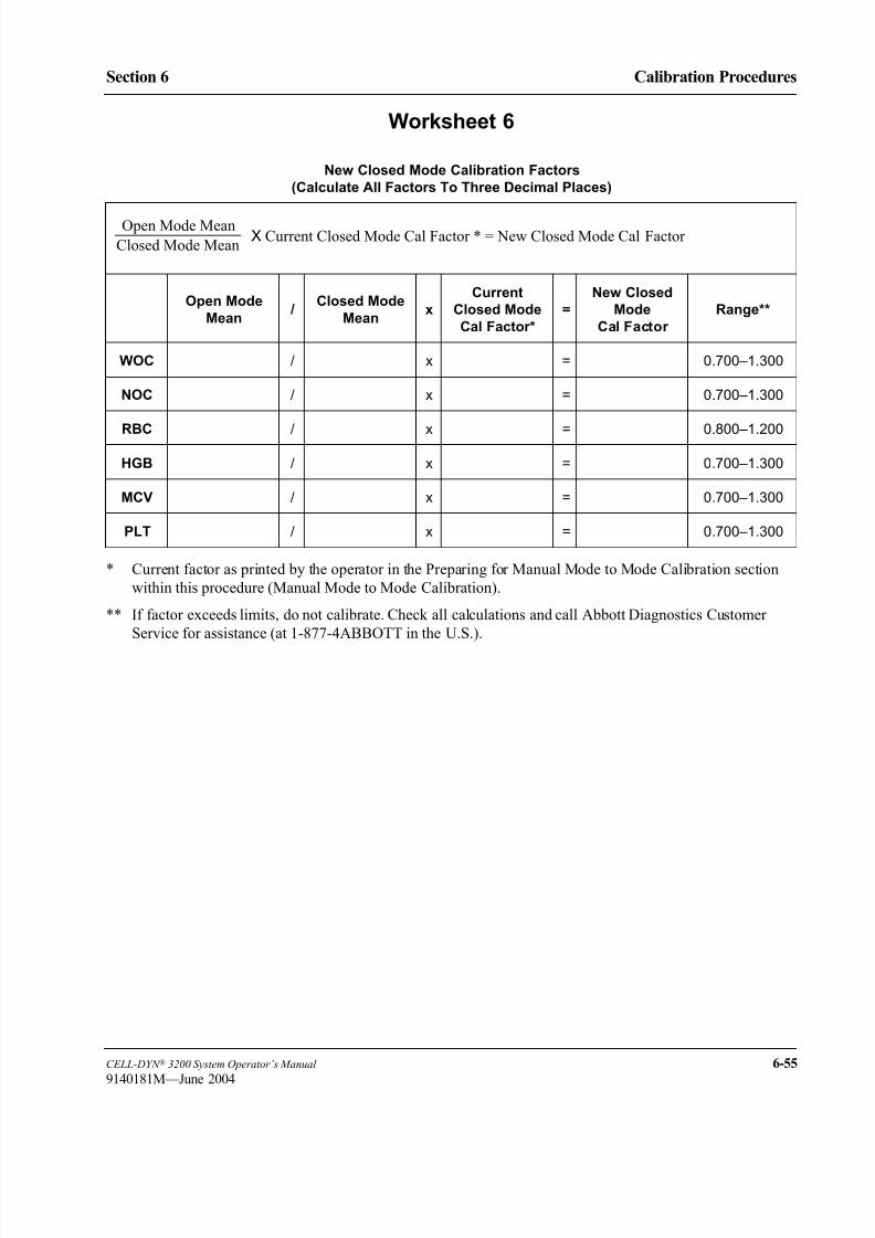
8/21/2019 Equ22-14 CellDyn3200 Op Man
http://slidepdf.com/reader/full/equ22-14-celldyn3200-op-man 359/690
CELL-DYN ® 3200 System Operator’s Manual 6-55
9140181M—June 2004
Section 6 Calibration Procedures
Worksheet 6
* Current factor as printed by the operator in the Preparing for Manual Mode to Mode Calibration section
within this procedure (Manual Mode to Mode Calibration).
** If factor exceeds limits, do not calibrate. Check all calculations and call Abbott Diagnostics Customer
Service for assistance (at 1-877-4ABBOTT in the U.S.).
New Closed Mode Calibration Factors
(Calculate All Factors To Three Decimal Places)
Open Mode
Mean /
Closed Mode
Meanx
Current
Closed Mode
Cal Factor*
=
New Closed
Mode
Cal Factor
Range**
WOC / x = 0.700–1.300
NOC / x = 0.700–1.300
RBC / x = 0.800–1.200
HGB / x = 0.700–1.300
MCV / x = 0.700–1.300
PLT / x = 0.700–1.300
Open Mode Mean
Closed Mode MeanX Current Closed Mode Cal Factor * = New Closed Mode Cal Factor

8/21/2019 Equ22-14 CellDyn3200 Op Man
http://slidepdf.com/reader/full/equ22-14-celldyn3200-op-man 360/690
6-56 CELL-DYN ® 3200 System Operator’s Manual
9140181H—October 2001
Calibration Procedures
Manual Calibration Worksheets Section 6
1. Select QC as the specimen type and run the calibrator or fresh whole blood sample 5 times.
2. Enter the mean from the QC file statistics for each parameter that was calibrated.
3. Enter the reference or assay values used to calibrate those parameters.
4. Calculate the difference between the mean and the reference or assay value.
5. Compare the difference with the Tolerance Limit. If it is within the limit, calibration is confirmed. QC
specimen type allows confirmation of both WOC and NOC values.
* For Calibrator, use the pre-established tolerance limits found on the Calibrator Assay Sheet.
For Fresh Whole Blood, each laboratory should establish tolerance limits according to its protocol.
Worksheet 7
Calibration Confirmation
QC Specimen Type
Sample # WOC NOC RBC HGB MCV PLT
Mean Value of
3/5 Runs
Reference or
Assay Value
Difference
(absolute
value)
ToleranceLimits *

8/21/2019 Equ22-14 CellDyn3200 Op Man
http://slidepdf.com/reader/full/equ22-14-celldyn3200-op-man 361/690
CELL-DYN ® 3200 System Operator’s Manual 6-57
9140181K—July 2002
Section 6 Calibration Procedures
References
1. ICSH, Protocol for Evaluation of Automated Blood Cell Counters, Clinicaland Laboratory Hematology 1988, 10:203, 212.
2. NCCLS standard H7-A, Procedure for Determining Packed Cell Volume by
the Microhematocrit Method ; Approved Standard (1985).

8/21/2019 Equ22-14 CellDyn3200 Op Man
http://slidepdf.com/reader/full/equ22-14-celldyn3200-op-man 362/690
6-58 CELL-DYN ® 3200 System Operator’s Manual
9140181H—October 2001
Calibration Procedures
References Section 6
NOTES

8/21/2019 Equ22-14 CellDyn3200 Op Man
http://slidepdf.com/reader/full/equ22-14-celldyn3200-op-man 363/690
CELL-DYN ® 3200 System Operator’s Manual 7-1
9140181K—July 2002
Section 7 Operational Precautions and Limitations
ec on perat ona recaut ons an m tat ons
Overview
This section deals with the precautions that need to be taken to ensure the performance and validity of the CELL-DYN 3200 System and its test results.
The following system precautions and limitations are reviewed in this section:
• General Limitations
• Location Requirements
• Reagent Storage and Handling
• Printer Precautions
Limitations
The CELL-DYN 3200 System is designed for in vitro diagnostic use.
• Abbott has designed the CELL-DYN 3200 System components for optimal
performance. Substituting reagents, calibrators, controls, and components
manufactured by other companies may adversely affect the performance of
the instrument.
• Follow the recommended maintenance schedules and procedures as outlined
in Section 9: Service and Maintenance.
• During the warranty period, all service and repair must be performed by
Abbott-authorized representatives.
Location Requirements
The location of the CELL-DYN 3200 System is an important consideration that
affects proper instrument functioning, operating safety, and ease of use.
• An Abbott-authorized representative must install the instrument.
• The location should have nonporous, nonabsorbing work surfaces and
flooring that can be cleaned easily and disinfected using recommended
procedures.
• Place the CELL-DYN 3200 System on a hard, level surface. Locate the
system:
– away from direct sunlight.
– away from the path of a cooled air or heated air outlet.
– away from other instruments that may interfere with the
CELL-DYN 3200 System, such as drying ovens, centrifuges, x-ray
equipment, MRI (magnetic resonance imaging) equipment, CRTs or
computers, video terminals, copiers, ultrasonic cleaners, and patient
areas. Please note that the CELL-DYN 3200 System has been evaluated
to EN55011 and EN61000 for electromagnetic emissions and immunity,
respectively.

8/21/2019 Equ22-14 CellDyn3200 Op Man
http://slidepdf.com/reader/full/equ22-14-celldyn3200-op-man 364/690
7-2 CELL-DYN ® 3200 System Operator’s Manual
9140181K—July 2002
Operational Precautions and Limitations
Overview Section 7
• Do not place reagent containers above the Analyzer.
• The following space should be available to ensure proper ventilation:
– Bench top space: approximately 6 linear feet to accommodate the
instrument, display station, and printer
– Below the instrument: sufficient space for reagents and waste container(if one is used)
– Behind the instrument: 6 inches of space for proper ventilation
– Above the instrument: 6 inches of space for proper ventilation
– Left side of instrument: 12 inches of space in front of the fan for proper
ventilation
• Allow adequate space around the instrument to perform necessary
maintenance procedures, to provide service access, and to allow the
instrument to be easily disconnected from its power source.
• Care should be taken to prevent blocking of the air vents or fans on the sidesand the back of the instrument.
• Before operating the instrument for the first time, verify that each reagent line
is connected to the appropriate inlet and reagent container. Refer to
Section 2: Installation Procedures and Special Requirements .
• Make sure the waste line is connected to the appropriate outlet and routed to
a suitable waste container or drain. If the waste is routed to a waste container,
make sure the waste sensor is properly connected. If the waste is routed to a
drain, make sure a Dummy Plug is inserted in the Waste Sensor Connector.
• The printer and Display Station can be placed on top of the instrument.

8/21/2019 Equ22-14 CellDyn3200 Op Man
http://slidepdf.com/reader/full/equ22-14-celldyn3200-op-man 365/690
CELL-DYN ® 3200 System Operator’s Manual 7-3
9140181H—October 2001
Section 7 Operational Precautions and Limitations
Precautions
Reagent Storage and Handling• Store reagents, calibrators, and controls according to the directions contained
in the package labels and/or inserts.
• Protect reagents from extreme heat and freezing during storage.
Temperatures below 0°C (32°F) may cause layering that changes the tonicity
and conductivity of the reagent. If freezing occurs, do not use the reagent.
• Protect reagents from direct sunlight, evaporation, and contamination. Use
the Reagent Container Cap attached to each length of inlet tubing to minimize
evaporation and contamination.
• Never add remaining reagent from a container being replaced to a freshly
opened container. This may contaminate the new reagent.
• Never use a hemoglobin standard other than the one specified for the
CELL-DYN 3200 System. The CELL-DYN 3200 System uses a
cyanide-free reagent.
Printer Precautions
The printhead on dot matrix printers can get very hot during extended periods of
printing. Allow it to cool before touching it. Heat is not a problem with ink jet or
bubble jet printers.

8/21/2019 Equ22-14 CellDyn3200 Op Man
http://slidepdf.com/reader/full/equ22-14-celldyn3200-op-man 366/690
7-4 CELL-DYN ® 3200 System Operator’s Manual
9140181H—October 2001
Operational Precautions and Limitations
Precautions Section 7
NOTES

8/21/2019 Equ22-14 CellDyn3200 Op Man
http://slidepdf.com/reader/full/equ22-14-celldyn3200-op-man 367/690
CELL-DYN ® 3200 System Operator’s Manual 8-1
9140181K—July 2002
Section 8 Hazards
ec on azar s
Overview
Operation, maintenance and servicing of automated hematology systems mayexpose individuals to potential safety and health hazards. All work must be
performed as described in the CELL-DYN Operator’s Manual or as directed by an
Abbott Representative.
This section provides precautionary warnings and information necessary for the
safe use of the CELL-DYN 3200 System. Supplementary warnings are inserted
throughout this manual and on the instrument to alert personnel to potential
hazards. Whenever hazard symbols are encountered on the instrument, users must
consult the Operator’s Manual to determine the nature of the potential hazard and
actions that must be taken.
The standard warning conventions including signal words (e.g., caution) and
symbols are described below. Safety symbols appear next to signal words thatidentify hazards.
Warning Conventions
Signal Words
DANGER: Denotes an immediate hazard which, if not avoided, could result in
serious injury or death.
WARNING: Denotes a hazard which, if not avoided, could result in moderate to
serious injury.
CAUTION: Denotes a potential hazard that could result in injury. Also, used for
conditions or activities which could interfere with proper func-
tioning of the instrument.
NOTE: Denotes special operator/service information or standard practices.
Symbols
The general hazard symbol identifies an activity or area that may present a
hazard to personnel or equipment.
The electrical hazard symbol alerts personnel to the possibility of electrical
shock if procedural or engineering controls are not observed.
The biohazard symbol identifies an activity or area where personnel may be
exposed to infectious substances if procedural or engineering controls are
not observed.
The laser hazard symbol identifies an activity or area where personnel will
be exposed to an eye hazard if procedural or engineering controls are not
observed.

8/21/2019 Equ22-14 CellDyn3200 Op Man
http://slidepdf.com/reader/full/equ22-14-celldyn3200-op-man 368/690
8-2 CELL-DYN ® 3200 System Operator’s Manual
9140181K—July 2002
Hazards
Overview Section 8
NOTES

8/21/2019 Equ22-14 CellDyn3200 Op Man
http://slidepdf.com/reader/full/equ22-14-celldyn3200-op-man 369/690
CELL-DYN ® 3200 System Operator’s Manual 8-3
9140181K—July 2002
Section 8 Hazards
Hazard Information and Precautions
GeneralAutomated hematology instruments require the handling of whole blood and blood
components by laboratory personnel. In addition, personnel must conduct
maintenance to ensure proper performance of the instrument. These activities
result in potential contact with infectious substances and other hazards. The
following are warnings, precautions, and standard practices to help prevent injury.
CAUTION: If the instrument is used or modified in a manner not specified
by the manufacturer, the protection provided by the instrument may be
impaired.
BiohazardsWARNING: Potential Biohazard. Consider all clinical specimens,
reagents, controls, surfaces or components that contain or have contacted
blood, serum, or other bodily fluid as potentially infectious. Wear gloves,
lab coats, and safety glasses, and follow other biosafety practices as speci-
fied in the OSHA Bloodborne Pathogen Rule (29CFR Part 1910.1030) or
other equivalent biosafety procedures.
WARNING: Potential Biohazard. The aspiration needle and probe are
sharp and potentially contaminated with infectious material. Avoid contact
with the tips of the probe and needle.
Spills of potentially infectious materials should be cleaned up in accordance with
established biosafety practices. A generally accepted procedure for cleaning such
spills is to absorb the spill with toweling or other absorbent material, wipe the area
with an appropriate tuberculocidal disinfectant such as 0.5% sodium hypochlorite
solution (refer to formula in Section 9: Service and Maintenance, Subsection:
Decontamination Procedures).
Prior to maintenance, service, or shipping, the instrument should be
decontaminated in accordance with the procedures specified in Section 9: Service
and Maintenance, Subsection: Decontamination Procedures and/or Preparation
for Shipping or Extended Period of Non-Use as appropriate. Remove and dispose
of contaminated disposables in accordance with local, state, and federal
regulations.
Handling and Disposing of Biohazardous Materials
Dispose of liquid and solid waste in accordance with local, state, and federal
regulations. Probes, needles, broken glass, and other sharps that are contaminated
with potentially infectious substances should be collected in a “sharps” container
for disposal as regulated medical waste. Contaminated gloves, wipes, swabs, and
other disposables should be placed in a standard medical waste container.

8/21/2019 Equ22-14 CellDyn3200 Op Man
http://slidepdf.com/reader/full/equ22-14-celldyn3200-op-man 370/690
8-4 CELL-DYN ® 3200 System Operator’s Manual
9140181K—July 2002
Hazards
Hazard Information and Precautions Section 8
Chemical Hazards
Prevent exposure to chemicals used in the operation and maintenance of the
CELL-DYN 3200 System (including reagents) by using appropriate personal
protective equipment, work procedures, and information on Material Safety Data
Sheets (MSDS). Refer to Section 2: Installation Procedures and Special
Requirements for an installation procedure for chemical containers.
Electrical Hazards
Basic electrical hazard awareness is essential to the safe operation of any
hematology analyzer. To ensure safe operation of the CELL-DYN 3200 System:
• Periodically inspect electrical cabling into and on the instrument for signs of
wear or damage.
• When moving equipment, lift all power cables clear of all system components.
CAUTION: Electrical Hazard. Do not disconnect any electrical connec-
tion while the power is on. Follow instructions for correctly powering down
the instrument and all connected equipment before performing maintenance
on parts which require protective covers to be removed for access. Use only
approved power cords and electrical accessories, supplied with the instru-
ment, or provided by Abbott, to protect against electrical shock.
CAUTION: Electrical Hazard. Turn off the power to the instrument and
disconnect the power cord before removing any instrument panel that is
securely fastened in place by screws or prior to replacing fuses. Replace
only the externally accessible fuse located immediately above the power
cord connector on the rear panel of the instrument. Use replacement fuses
only of the specified type and electrical rating.
• Keep liquids away from all electrical connectors (such as electrical outlets)
or communication connectors (such as the LIS connector).
• Keep the floor dry.
• The electrical circuit spacing of the CELL-DYN 3200 System is based on
pollution degree (1) and altitude [up to 2000 M (6500 ft)] as per IEC
61010-1. Pollution degree 1 is defined as an environment where there is no
pollution or only dry, non-conductive pollution.
CAUTION: If the instrument is used or modified in a manner not specified
by the manufacturer, the protection provided by the instrument may be
impaired.

8/21/2019 Equ22-14 CellDyn3200 Op Man
http://slidepdf.com/reader/full/equ22-14-celldyn3200-op-man 371/690
CELL-DYN ® 3200 System Operator’s Manual 8-5
9140181K—July 2002
Section 8 Hazards
Physical and Mechanical Hazards
Observe these basic rules for mechanical safety:
• Carefully follow all procedures and instructions.
• Keep all protective covers in place when processing specimens.
• Never allow any part of your body to enter the region of movement of any
mechanical component when the instrument is operating.
• Do not wear articles of clothing or accessories that could catch on the
System; keep pockets free of items that could fall into the System; keep long
hair from catching on the System.
• Wear powder-free gloves and safety glasses when maintaining or repairing
the instrument.
• Avoid contact with needle tips at all times.
• Use professional assistance only when moving or lifting the instrument to
prevent injury.
• Use proper lifting techniques when moving reagent cubitainers to prevent injury.
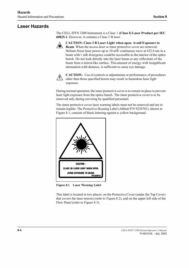
8/21/2019 Equ22-14 CellDyn3200 Op Man
http://slidepdf.com/reader/full/equ22-14-celldyn3200-op-man 372/690
8-6 CELL-DYN ® 3200 System Operator’s Manual
9140181K—July 2002
Hazards
Hazard Information and Precautions Section 8
Laser Hazards
The CELL-DYN 3200 Instrument is a Class 1 (Class I) Laser Product per IEC
60825-1. However, it contains a Class 3 B laser.
CAUTION: Class 3 B Laser Light when open. Avoid Exposure to
Beam. When the access door or inner protective cover are removed,Helium-Neon laser power up to 10 mW continuous wave at 632.8 nm in a
beam with 1 mR divergence could be accessible in the interior of the optics
bench. Do not look directly into the laser beam or any reflections of the
beam from a mirror-like surface. This amount of energy, with insignificant
attenuation with distance, is sufficient to cause eye damage.
CAUTION: Use of controls or adjustments or performance of procedures
other than those specified herein may result in hazardous laser light
exposure.
During normal operation, the inner protective cover is to remain in place to prevent
laser light exposure from the optics bench. The inner protective cover is to beremoved only during servicing by qualified personnel.
The inner protective cover laser warning labels must not be removed and are to
remain legible. The Protective Housing Label (Abbott P/N 9230701), shown in
Figure 8.1, consists of black lettering against a yellow background.
Figure 8.1 Laser Warning Label
This label is located in two places: on the Protective Cover (under the Top Cover)
that covers the laser mirrors (refer to Figure 8.2), and on the upper left side of the
Flow Panel (refer to Figure 8.3).
CAUTION –
CLASS 3B LASER LIGHT WHEN OPEN.
AVOID EXPOSURE TO BEAM.PN 923 7 1
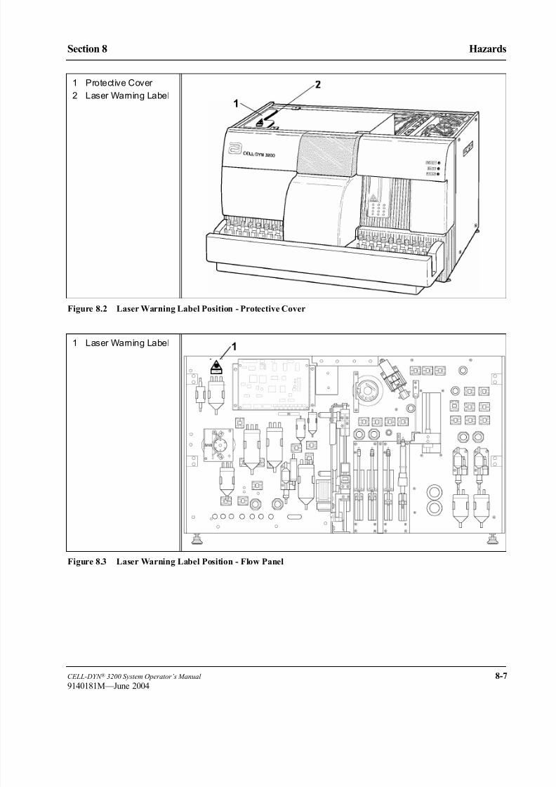
8/21/2019 Equ22-14 CellDyn3200 Op Man
http://slidepdf.com/reader/full/equ22-14-celldyn3200-op-man 373/690
CELL-DYN ® 3200 System Operator’s Manual 8-7
9140181M—June 2004
Section 8 Hazards
Figure 8.2 Laser Warning Label Position - Protective Cover
Figure 8.3 Laser Warning Label Position - Flow Panel
1 Protective Cover
2 Laser Warning Label
1 Laser Warning Label
1
CAUTION…
CLASS3BLASERL IGHTWHENOPEN.
AVOIDEXPOSURETOBEAM.P N9230701E
1
CAUTION–
CLASS3BLASERLIGHTWHENOPEN.
AVOIDEXPOSURETOBEAM.
PN 923 7 1
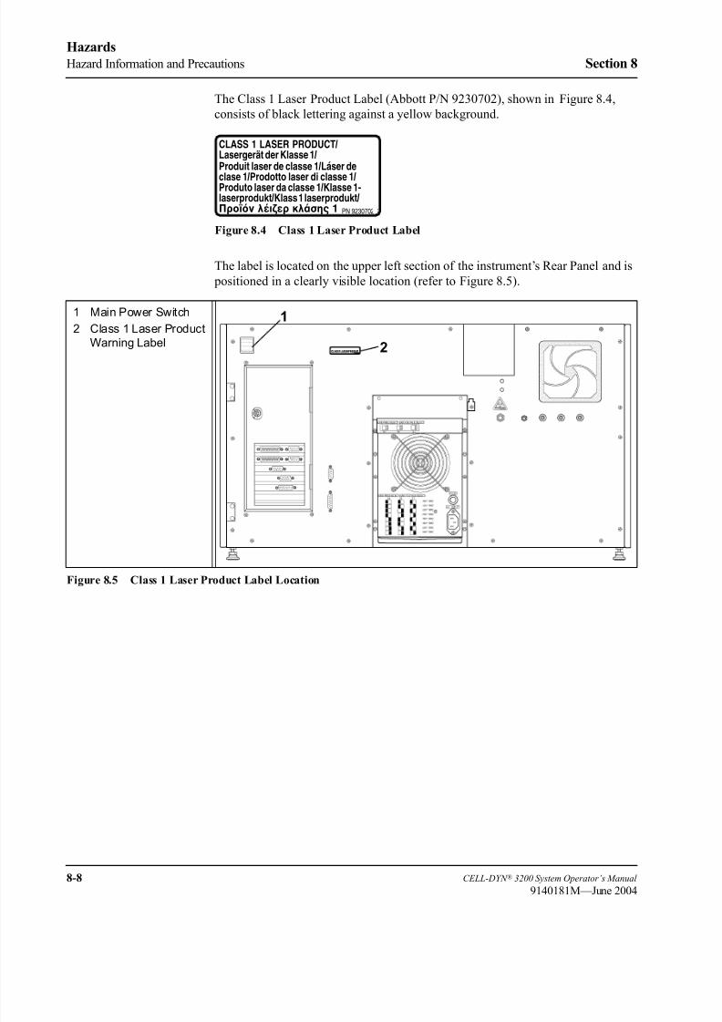
8/21/2019 Equ22-14 CellDyn3200 Op Man
http://slidepdf.com/reader/full/equ22-14-celldyn3200-op-man 374/690
8-8 CELL-DYN ® 3200 System Operator’s Manual
9140181M—June 2004
Hazards
Hazard Information and Precautions Section 8
The Class 1 Laser Product Label (Abbott P/N 9230702), shown in Figure 8.4,
consists of black lettering against a yellow background.
Figure 8.4 Class 1 Laser Product Label
The label is located on the upper left section of the instrument’s Rear Panel and is
positioned in a clearly visible location (refer to Figure 8.5).
Figure 8.5 Class 1 Laser Product Label Location
PN 9230702C
CLASS 1 LASER PRODUCT/Lasergert der Klasse 1/Produit laser de classe 1/Lser de
clase 1/Prodotto laser di classe 1/Produto laser da classe 1/Klasse 1-laserprodukt/Klass 1 laserprodukt/Προϊόν λέιζερ κλάσης 1
1 Main Power Switch
2 Class 1 Laser Product
Warning Label
1
2CLASS1LASERPRODUCTPN 923 7 2

8/21/2019 Equ22-14 CellDyn3200 Op Man
http://slidepdf.com/reader/full/equ22-14-celldyn3200-op-man 375/690
CELL-DYN ® 3200 System Operator’s Manual 8-9
9140181K—July 2002
Section 8 Hazards
References
1. Occupational Safety and Health Administration, 29 CFR Part 1910.1030.Department of Labor. Occupational Exposure to Bloodborne Pathogens;
Final Rule. 235:64175-64182, 1991.
2. IEC 60825-1, International Electrotechnical Commission World Standards
for electrical and electronic engineering, 60825: Safety of laser products,
60825-1 Part 1: Equipment classification, requirements, and users guide.

8/21/2019 Equ22-14 CellDyn3200 Op Man
http://slidepdf.com/reader/full/equ22-14-celldyn3200-op-man 376/690
8-10 CELL-DYN ® 3200 System Operator’s Manual
9140181K—July 2002
Hazards
References Section 8
NOTES

8/21/2019 Equ22-14 CellDyn3200 Op Man
http://slidepdf.com/reader/full/equ22-14-celldyn3200-op-man 377/690
CELL-DYN ® 3200 System Operator’s Manual 9-1
9140181H—October 2001
Section 9 Service and Maintenance
ec on erv ce an a ntenance
Overview
The CELL-DYN 3200 is designed to require minimal routine maintenance. Forexample:
• The fluidics are automatically rinsed between samples.
• The instrument is automatically placed in the Standby state if it has been idle
for four hours after the last cycle is completed.
The operator is encouraged to routinely perform the required maintenance in order
to ensure optimum performance. This section describes the recommended
preventive maintenance procedures for the Analyzer. Instructions are also given for
preparing the instrument for a prolonged period of inactivity.
Many required preventative maintenance procedures have been automated on the
CELL-DYN 3200. These programs can be accessed by pressing the[SPECIAL PROTOCOLS] key. The SPECIAL PROTOCOLS menu is discussed in the
next section followed by a discussion of Preventive Maintenance Schedule
Procedures.

8/21/2019 Equ22-14 CellDyn3200 Op Man
http://slidepdf.com/reader/full/equ22-14-celldyn3200-op-man 378/690
9-2 CELL-DYN ® 3200 System Operator’s Manual
9140181H—October 2001
Service and Maintenance
Overview Section 9
NOTES
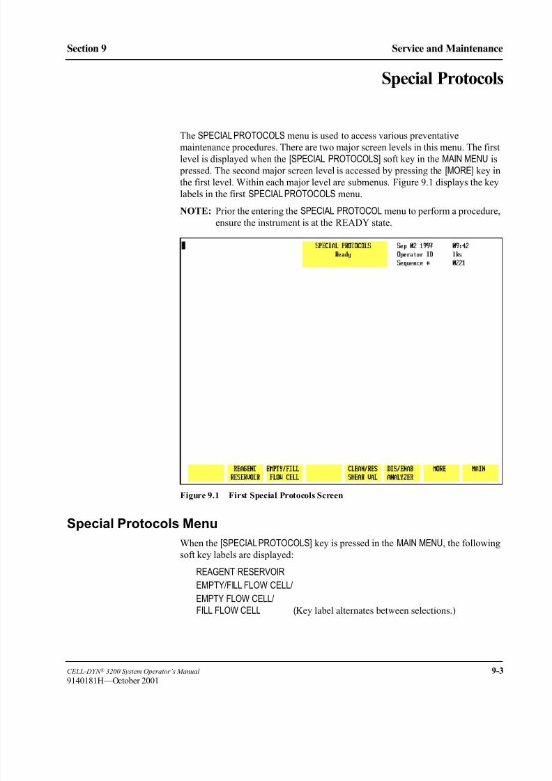
8/21/2019 Equ22-14 CellDyn3200 Op Man
http://slidepdf.com/reader/full/equ22-14-celldyn3200-op-man 379/690
CELL-DYN ® 3200 System Operator’s Manual 9-3
9140181H—October 2001
Section 9 Service and Maintenance
Special Protocols
The SPECIAL PROTOCOLS menu is used to access various preventativemaintenance procedures. There are two major screen levels in this menu. The first
level is displayed when the [SPECIAL PROTOCOLS] soft key in the MAIN MENU is
pressed. The second major screen level is accessed by pressing the [MORE] key in
the first level. Within each major level are submenus. Figure 9.1 displays the key
labels in the first SPECIAL PROTOCOLS menu.
NOTE: Prior the entering the SPECIAL PROTOCOL menu to perform a procedure,
ensure the instrument is at the READY state.
Figure 9.1 First Special Protocols Screen
Special Protocols Menu
When the [SPECIAL PROTOCOLS] key is pressed in the MAIN MENU, the followingsoft key labels are displayed:
REAGENT RESERVOIR
EMPTY/FILL FLOW CELL/
EMPTY FLOW CELL/FILL FLOW CELL (Key label alternates between selections.)
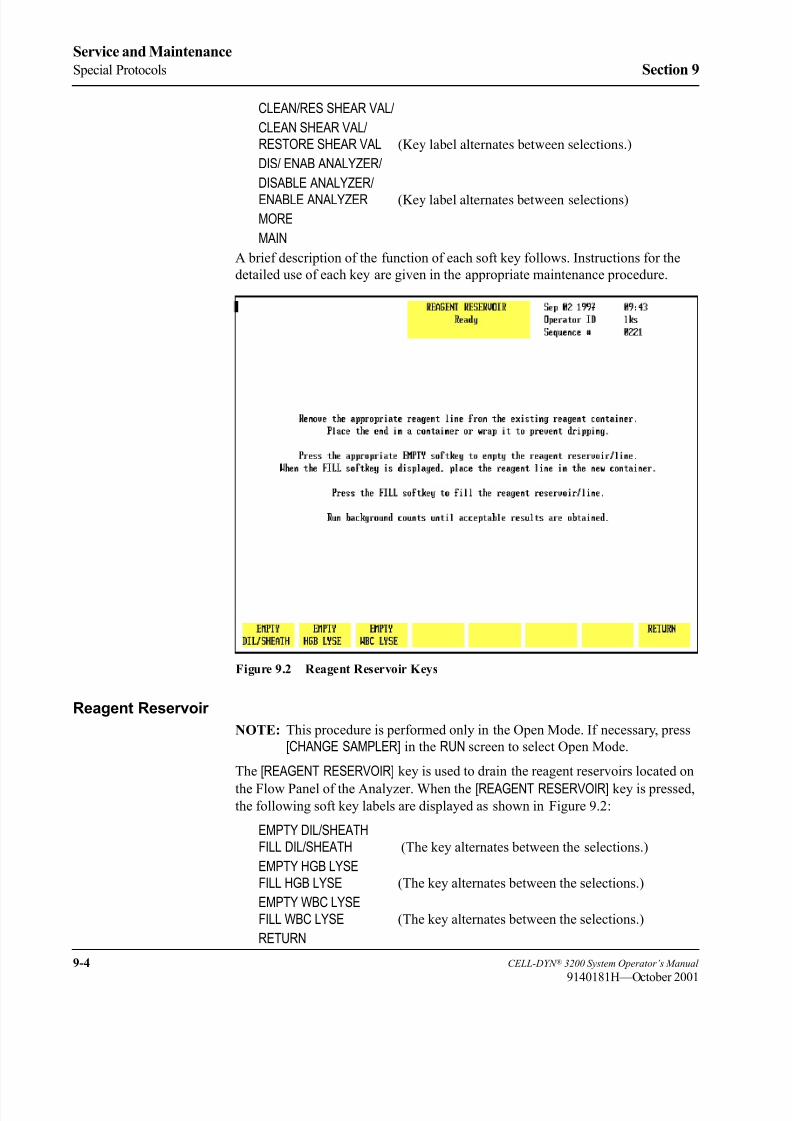
8/21/2019 Equ22-14 CellDyn3200 Op Man
http://slidepdf.com/reader/full/equ22-14-celldyn3200-op-man 380/690
9-4 CELL-DYN ® 3200 System Operator’s Manual
9140181H—October 2001
Service and Maintenance
Special Protocols Section 9
CLEAN/RES SHEAR VAL/
CLEAN SHEAR VAL/RESTORE SHEAR VAL (Key label alternates between selections.)
DIS/ ENAB ANALYZER/
DISABLE ANALYZER/
ENABLE ANALYZER (Key label alternates between selections)
MORE
MAIN
A brief description of the function of each soft key follows. Instructions for the
detailed use of each key are given in the appropriate maintenance procedure.
Figure 9.2 Reagent Reservoir Keys
Reagent Reservoir
NOTE: This procedure is performed only in the Open Mode. If necessary, press
[CHANGE SAMPLER] in the RUN screen to select Open Mode.
The [REAGENT RESERVOIR] key is used to drain the reagent reservoirs located on
the Flow Panel of the Analyzer. When the [REAGENT RESERVOIR] key is pressed,the following soft key labels are displayed as shown in Figure 9.2:
EMPTY DIL/SHEATHFILL DIL/SHEATH (The key alternates between the selections.)
EMPTY HGB LYSEFILL HGB LYSE (The key alternates between the selections.)
EMPTY WBC LYSE
FILL WBC LYSE (The key alternates between the selections.)
RETURN

8/21/2019 Equ22-14 CellDyn3200 Op Man
http://slidepdf.com/reader/full/equ22-14-celldyn3200-op-man 381/690
CELL-DYN ® 3200 System Operator’s Manual 9-5
9140181H—October 2001
Section 9 Service and Maintenance
The screen displays instructions for draining and filling the reagent reservoirs, as
shown in Figure 9.2.
Empty Dil/Sheath
When the [EMPTY DIL/SHEATH] key is pressed, the diluent and sheath reservoirs are
drained and the key toggles to [FILL DIL/ SHEATH]. When the [FILL DIL/SHEATH] keyis pressed, the diluent and sheath reservoirs are refilled.
Empty HGB Lyse
When the [EMPTY HGB LYSE] key is pressed, the HGB lyse supply tubing is drained
and the key toggles to [FILL HGB LYSE]. When the [FILL HGB LYSE] key is pressed,
the HGB lyse supply tubing is refilled.
Empty WBC Lyse
When the [EMPTY WBC LYSE] key is pressed, the WBC lyse supply tubing is
drained and the key toggles to [FILL WBC LYSE]. When the [FILL WBC LYSE] key is
pressed, the WBC lyse supply tubing is refilled.
Empty/Fill Flow Cell
NOTE: This procedure is performed only in the Open Mode. If necessary, press
[CHANGE SAMPLER] in the RUN screen to select Open Mode.
Pressing the [EMPTY/FILL FLOW CELL] key displays a submenu showing the [EMPTYFLOW CELL] and [RETURN] keys.
When the [EMPTY FLOW CELL] key is pressed, diluent/sheath in the Optical Flow
Cell is drained and the key toggles to [FILL FLOW CELL] upon completion.
When the [FILL FLOW CELL] key is pressed, the flow cell is refilled with diluent/
sheath.
Clean/Restore Shear Valve
NOTE: This procedure is performed only in the Open Mode. If necessary, press
[CHANGE SAMPLER] in the RUN screen to select Open Mode.
The [CLEAN/RES SHEAR VAL] key is used to prepare the shear valve for cleaning.
Pressing the [CLEAN/RES SHEAR VAL] key displays a submenu showing the [CLEANSHEAR VAL] and [RETURN] keys.
When the [CLEAN SHEAR VAL] key is pressed, the System partially empties the
syringes, flushing the reagents out of the shear valve and associated tubing. The
shear valve then rotates into the position necessary for its removal. After the shear
valve has rotated, the key toggles to [RESTORE SHEAR VAL].
When the [RESTORE SHEAR VAL] key is pressed, the syringes refill the shear valve
and the associated tubing, and the shear valve rotates back to its operational
position.
Disable/Enable Analyzer
When the [DIS/ENAB ANALYZER] key is pressed, a submenu is displayed showing
the [DISABLE ANALYZER] and [RETURN] keys.

8/21/2019 Equ22-14 CellDyn3200 Op Man
http://slidepdf.com/reader/full/equ22-14-celldyn3200-op-man 382/690
9-6 CELL-DYN ® 3200 System Operator’s Manual
9140181H—October 2001
Service and Maintenance
Special Protocols Section 9
Pressing the [DISABLE ANALYZER] key prevents the Analyzer from cycling while
certain maintenance procedures are performed. After the Analyzer has been
disabled, the key toggles to [ENABLE ANALYZER].
When the [ENABLE ANALYZER] key is pressed, the Analyzer is returned to the state
prior to disabling.
Figure 9.3 Second Special Protocols Screen
More
When the [MORE] key is pressed, the second SPECIAL PROTOCOLS screen and the
following soft key labels are displayed, as shown in Figure 9.3:
AUTO CLEAN
DAILY SHUTDOWN
PREPARE SHIPPING
CLEAN NEEDLE
EXTENDED AUTOCLEAN
MOREMAIN
Auto-Clean
NOTE: This procedure is performed only in the Open Mode. If necessary, press
[CHANGE SAMPLER] in the RUN screen to select Open Mode.

8/21/2019 Equ22-14 CellDyn3200 Op Man
http://slidepdf.com/reader/full/equ22-14-celldyn3200-op-man 383/690
CELL-DYN ® 3200 System Operator’s Manual 9-7
9140181H—October 2001
Section 9 Service and Maintenance
The [AUTO CLEAN] key is used to initiate the Auto-Clean cycle. The Shear Valve,
the RBC/PLT Mixing Chamber, the WBC Mixing Chamber, the Optical Flow Cell,
the HGB Flow Cell, and all of the associated fluidics are automatically cleaned and
rinsed during this cycle.
When the [AUTO CLEAN] key is pressed, the screen displays a set of instructions and
the two following soft key labels:
AUTO CLEAN
RETURN
Press [ AUTO CLEAN] again to activate the Auto-Clean cycle. Press [RETURN] toreturn to the second SPECIAL PROTOCOLS screen.
Daily Shutdown
The [DAILY SHUTDOWN] key is used to initiate the Daily Shutdown cycle. During
the cycle, the fluidics are automatically drained and rinsed. At the end of the cycle,
the Analyzer is placed in STANDBY. The electronic solenoid valves are
automatically opened periodically while the Analyzer is in Standby to prevent the
tubing from becoming pinched.
Prepare Shipping
NOTE: This procedure is performed only in the Open Mode. If necessary, press
[CHANGE SAMPLER] in the RUN screen to select Open Mode.
The [PREPARE SHIPPING] key is used to prepare the Analyzer for shipment or an
extended period of inactivity. The cycle drains all of the reagents from the system
and then rinses the fluidics with deionized water supplied by the operator.
Clean Needle
The [CLEAN NEEDLE] key is used to clean the needle in the Tower module. Whenthe key is pressed, the needle is forcefully rinsed with diluent.
Extended Auto-Clean
NOTE: This procedure is performed only in the Open Mode. If necessary, press
[CHANGE SAMPLER] in the RUN screen to select Open Mode.
The [EXTENDED AUTOCLEAN] key is used to initiate the Extended Auto-Clean
cycle, which is a longer version of the Auto-Clean cycle.
When the [EXTENDED AUTO CLEAN] key is pressed, the screen displays the
message shown in Figure 9.8 in the Extended Auto-Clean subsection. The
following soft key labels are displayed:
EXTENDED AUTO CLEAN
RETURN
Press [EXTENDED AUTO CLEAN] again to activate the Extended Auto-Clean cycle.
Press [RETURN] to return to the second Special Protocols screen.
More
The [MORE] key is used to return to the first SPECIAL PROTOCOLS menu.

8/21/2019 Equ22-14 CellDyn3200 Op Man
http://slidepdf.com/reader/full/equ22-14-celldyn3200-op-man 384/690
9-8 CELL-DYN ® 3200 System Operator’s Manual
9140181H—October 2001
Service and Maintenance
Special Protocols Section 9
NOTES
8/21/2019 Equ22-14 CellDyn3200 Op Man
http://slidepdf.com/reader/full/equ22-14-celldyn3200-op-man 385/690
CELL-DYN ® 3200 System Operator’s Manual 9-9
9140181M—June 2004
Section 9 Service and Maintenance
Preventive Maintenance Schedule
OverviewThe maintenance schedule outlined on the following page will minimize
operational problems with the CELL-DYN 3200. The recommended intervals are
based on instruments operating in laboratories that process samples from a general
patient population. The intervals are affected by the following variables:
• Volume of samples processed
• Workload schedule
• Operating environment
• Patient population being analyzed
Each laboratory must assess its own situation and modify these recommendedintervals as necessary.
CAUTION: Gloves should be worn during the maintenance procedures.
They should be powder-free or rinsed before performing the maintenance
as powder may cause instrument problems. (For example, powder may
clog ports in the shear valve and cause it to leak.)
IMPORTANT: Overdue maintenance is usually indicated by an increase in
imprecision of one or more of the directly measured parameters. This increase is
due to carryover or dilution/sampling inconsistencies. If this occurs on more than
a random basis, the appropriate maintenance should be performed more frequently.
A diagram of the analyzer flow panel is included to assist in component
identification and location.
If you encounter trouble performing any of these maintenance procedures, contact
Abbott Diagnostics Customer Service at: 1 (877) 4ABBOTT (1-877-422-2688).
To order any parts, accessories, or consumables, refer to
Appendix B — Parts and Accessories.

8/21/2019 Equ22-14 CellDyn3200 Op Man
http://slidepdf.com/reader/full/equ22-14-celldyn3200-op-man 386/690
9-10 CELL-DYN ® 3200 System Operator’s Manual
9140181L—July 2003
Service and Maintenance
Preventive Maintenance Schedule Section 9
Preventive Maintenance Schedule
The following procedures should be performed at the scheduled time intervals or
more often, depending on usage, as determined by each individual laboratory.
Keep a record of routine maintenance and parts replacement to ensure proper
equipment care and to assist Abbott Customer Service Specialists and Abbott FieldService Representatives in diagnosing instrument problems.
Daily
Run Auto-Clean Cycle
Clean Closed Sample Aspiration Needle
Clean Closed Sample Tower
Weekly
Clean Sample Loader and Racks
Check Sample Transfer Pump Tubing
Run the Extended Auto-Clean Cycle if routinely running reticulocyte counts.
Monthly
Clean Fan Filter
Run Extended Auto-Clean
Replace Diluent/Sheath Filter
Semi-Annual
Clean Printer
Nonscheduled Maintenance Procedures
Clean Shear Valve
Clean Interior of Open Sample Aspiration Probe
Unclog Open Sample Aspiration Probe
Clean Interior of Closed Sample Aspiration Needle
Unclog Closed Sample Aspiration Needle
Clean Syringes
Clean HGB Flow Cell
Clean Bar Code Reader Window
Clean Reagent Lines
Replace Open Sample Aspiration Probe
Replace Closed Sample Aspiration Needle
Replace Tubing in Sample Transfer Pump

8/21/2019 Equ22-14 CellDyn3200 Op Man
http://slidepdf.com/reader/full/equ22-14-celldyn3200-op-man 387/690
CELL-DYN ® 3200 System Operator’s Manual 9-11
9140181M—June 2004
Section 9 Service and Maintenance
Replace Tubing in Normally Closed Valves
Replace Syringes
Replace Fuse
Prepare for Shipping or Extended Period of Non-Use
Clean Y Valve
Clean Tube Deflector (Brush)
Flow Panel Components
Figure 9.4 illustrates the Flow Panel components that may be inspected, cleaned,
or replaced during normal maintenance procedures.
Figure 9.4 Analyzer Flow Panel Components
1 Vent
2 Sample Transfer
Peristaltic Pump
3 Waste Chambers4 WBC Mixing Chamber
5 RBC Mixing Chamber
6 HGB Flow Cell
7 Shear Valve
8 Y Valve
9 Open Sample Probe
(With Wash Block)
10 Normally Closed
Valves
11 Diluent Reservoir
12 Sheath Reservoir
13 Normally Closed
Valves
14 Diluent/Sheath Filter
15 Tube Spinner
16 Closed Sample
Needle (With Wash
Block)
17 Sample Injection
Syringe
18 HGB Lyse Syringe
19 WBC Lyse Syringe
20 Diluent/SheathSyringe
21 Waste Chambers
1 2 3 7 8
10
94 5 6
11 12 13 14 15 17 18 19 20 2116

8/21/2019 Equ22-14 CellDyn3200 Op Man
http://slidepdf.com/reader/full/equ22-14-celldyn3200-op-man 388/690
9-12 CELL-DYN ® 3200 System Operator’s Manual
9140181K—July 2002
Service and Maintenance
Preventive Maintenance Schedule Section 9
Decontamination Procedures
The OSHA Bloodborne Pathogen Rule (29 CFR Part 1910.1030) requires the
decontamination of laboratory equipment prior to servicing or shipment:
• Decontaminate the instrument by performing the Auto-Clean cycle. This
cycle flushes all of the fluid pathways with reagents to purge any waste fromthe fluid pathways. The Open Mode Sample Probe and the Closed Sample
Needle (CS Model) or Sample Loader Needle (SL Model) are automatically
rinsed after every cycle. The surfaces of the instrument should be wiped with
a nonabrasive detergent solution to remove any soiling, then wiped with a
tuberculocidal disinfectant, such as a 0.5% sodium hypochlorite solution.
To calculate the percent (%) sodium hypochlorite concentration desired see the
following formula:
A = Percent (%) of sodium hypochlorite solution desired
B = Percent (%) of sodium hypochlorite stock solution (as purchased)
X = Parts of water to be mixed with one part of the sodium hypochlorite stocksolution
Example:
If you need a 0.5% solution of sodium hypochlorite for a cleaning procedure, and
the label on the bottle of bleach states that it is 5.25% sodium hypochlorite, then:
Add 9.5 parts deionized water to 1 part bleach to obtain a 0.5% sodium
hypochlorite solution, or 9.5 mL of deionized water to 1.0 mL of bleach (5.25%
sodium hypochlorite) to obtain 10.5 mL of a 0.5% solution of sodium hypochlorite.
If the instrument is to be shipped, it must be decontaminated prior to shipment. This
is accomplished by pressing the [PREPARE FOR SHIPPING] key in the SPECIALPROTOCOLS menu. Instructions for this procedure are given in section
Preparation for Shipping or Extended Period of Non-Use.
X = B - A
A
X =
5.25 -.5
.5 X = 9.5

8/21/2019 Equ22-14 CellDyn3200 Op Man
http://slidepdf.com/reader/full/equ22-14-celldyn3200-op-man 389/690
CELL-DYN ® 3200 System Operator’s Manual 9-13
9140181H—October 2001
Section 9 Service and Maintenance
Daily Maintenance Procedures
Auto-CleanWARNING: Potential Biohazard. Wear gloves, lab coats, and safety
glasses and follow other biosafety practices as specified in the OSHA
Bloodborne Pathogen Rule (29 CFR Part 1910.1030) or other equivalent
biosafety procedures.
The Auto-Clean Cycle is a fully automated cycle designed to clean the Shear
Valve, RBC/PLT Mixing Chamber, the WBC Mixing Chamber, the Optical Flow
Cell, the HGB Flow Cell, Open Sample Probe, the needle in the Tower Module,
and all the associated fluidics. The forward and reverse action of the peristaltic
pump is used during this cycle to gently scrub and remove any fibrin or debris
within the system. The Auto-Clean cycle takes approximately 12 minutes. Whenthe [AUTO CLEAN] key is pressed, instructions are displayed on the screen, as shown
in Figure 9.5.
NOTE: The Auto-Clean cycle should be run prior to performing any maintenance
procedure. This ensures that all waste is purged from the fluid pathways.
Figure 9.5 Auto-Clean Screen

8/21/2019 Equ22-14 CellDyn3200 Op Man
http://slidepdf.com/reader/full/equ22-14-celldyn3200-op-man 390/690
9-14 CELL-DYN ® 3200 System Operator’s Manual
9140181H—October 2001
Service and Maintenance
Daily Maintenance Procedures Section 9
Materials Required
1. CELL-DYN Enzymatic Cleaner. Enzymatic cleaner should be used at room
temperature but stored at a temperature between 2°C and 8°C
(36°F and 46°F).
2. Clean VACUTAINER ® tube or other clean container
3. Lint-free pads
4. Deionized water
Procedure—CS and SL Models
1. The instrument should be in the Open Mode. If necessary, press the [CHANGESAMPLER] key in the RUN screen to select the Open Mode.
2. With the Wash Block raised, carefully wipe the outside of the Open Sample
Aspiration Probe and the bottom of the Wash Block with a lint-free pad that
has been dampened with diluted enzymatic cleaner (one part distilled water
to one part enzymatic cleaner).
3. In the MAIN MENU, press [SPECIAL PROTOCOLS] f ollowed by [MORE] toaccess the Auto-Clean function.
4. Press [AUTO CLEAN]. Instructions for performing the procedure are displayed
on the screen.
5. Dispense approximately 1.5 mL of Enzymatic Cleaner into the
VACUTAINER ® or other clean container and hold the container under the
probe.
6. Press [AUTO CLEAN] to activate the cleaning cycle.
NOTE: Do not press the Touch Plate. The Auto-Clean cycle is only
initiated by the [AUTO CLEAN] key.
7. Continue to hold the container under the probe until a beep tone is heard.
Remove the container and discard the remaining enzymatic cleaner.
8. When the Auto-Clean cycle is completed, three background counts are run to
rinse the system. Check that the background counts are acceptable before
running controls or patient samples. If the counts are unacceptable,
troubleshoot accordingly (refer to Section 10: Troubleshooting and
Diagnostics; Subsection: Troubleshooting Guide).

8/21/2019 Equ22-14 CellDyn3200 Op Man
http://slidepdf.com/reader/full/equ22-14-celldyn3200-op-man 391/690
CELL-DYN ® 3200 System Operator’s Manual 9-15
9140181H—October 2001
Section 9 Service and Maintenance
Clean Aspiration Needle
The Aspiration Needle in the Tower Module should be cleaned regularly to remove
protein buildup or debris and reduce the possibility of a blockage. The procedure
for cleaning the needle differs slightly on the CS and SL models. Both procedures
are described below.
WARNING: Potential Biohazard. The needle in the Tower Module is
sharp and potentially contaminated with infectious materials. Avoid any
contact with the needle.
Materials Required
1. CELL-DYN Enzymatic Cleaner
2. Diluent
3. Three empty VACUTAINER ® tubes
4. Gloves, lab coat, and safety glasses
Procedure — SL Model
1. Aliquot approximately 2 mL of Enzymatic Cleaner into one of the
VACUTAINER ® tubes.
2. Aliquot approximately 2 mL of diluent each into the other two
VACUTAINER ® tubes.
3. If necessary, press the [CHANGE SAMPLER] soft key in the RUN screen to
select the Closed Mode.
4. In the RUN screen, press [SPECIMEN TYPE] followed by [BACKGROUND].
5. Place the enzymatic cleaner tube followed by the two diluent tubes in a
Sample Loader rack.
NOTE: A convenient way to perform this procedure is to add the tubes to
the end of the last run of the day.
6. Position the rack on the load side of the Sample Loader (refer to Figure 13.7
if necessary). Make sure the Tower Cover is closed.
CAUTION: The Sample Loader will not operate unless the Tower Cover
is in place.
7. Press the [START LOADER] key to initiate processing.
8. Audible beep tones indicate that processing is completed.
9. Run at least three background counts to rinse the system. Check that the
background counts are acceptable before running controls or patient samples.If the counts are unacceptable, troubleshoot accordingly (refer to Section 10:
Troubleshooting and Diagnostics; Subsection: Troubleshooting Guide).
10. When cleaning is completed, remain in the RUN screen to process patient
samples or press [MAIN] to return to the MAIN MENU.

8/21/2019 Equ22-14 CellDyn3200 Op Man
http://slidepdf.com/reader/full/equ22-14-celldyn3200-op-man 392/690
9-16 CELL-DYN ® 3200 System Operator’s Manual
9140181H—October 2001
Service and Maintenance
Daily Maintenance Procedures Section 9
Procedure — CS Model
1. Aliquot approximately 2 mL of Enzymatic Cleaner into one of the
VACUTAINER ® tubes.
2. Aliquot approximately 2 mL of diluent each into the other two
VACUTAINER ® tubes.
3. If necessary, press the [CHANGE SAMPLER] soft key in the RUN screen to
select the Closed Mode.
4. In the RUN screen, press [SPECIMEN TYPE] followed by [BACKGROUND].
5. Open the Tower Door, place the tube containing the Enzymatic Cleaner in the
Door Assembly, and close the door.
6. Press the Touch Plate to run the Enzymatic Cleaner. When aspiration is
finished, remove the tube.
7. Repeat steps 5 and 6 using the two diluent tubes.
8. Run at least three background counts to rinse the system. Check that the
background counts are acceptable before running controls or patient samples.
If the counts are unacceptable, troubleshoot accordingly (refer to Section 10:Troubleshooting and Diagnostics; Subsection: Troubleshooting Guide).
Closed Sample Tower
Daily cleaning of the Tower Module is recommended when the Closed Mode is
used.
Materials Required
1. Cleaning solution (0.5% sodium hypochlorite solution). See the formula for
mixing this solution under Decontamination Procedures earlier in this
section.
2. Clean, warm water for rinse
3. Lint-free pads (or other lint-free pads)
4. Gloves, lab coat, and safety glasses
Procedure
1. Lift the Tower Cover up and off the instrument.
2. Clean the following components with a lint-free pad moistened with the
cleaning solution prepared above.
a. Spin mechanism, including belt if necessary
b. Under the Wash Block if there is evidence of residue build-up
c. Any other area that appears to have been contaminated by specimen or
reagents.
3. Rinse the components using a lint-free pad moistened with warm water.
4. Dry the components with a lint-free pad.
5. When finished, replace the Tower Cover.

8/21/2019 Equ22-14 CellDyn3200 Op Man
http://slidepdf.com/reader/full/equ22-14-celldyn3200-op-man 393/690
CELL-DYN ® 3200 System Operator’s Manual 9-17
9140181M—June 2004
Section 9 Service and Maintenance
Sample Loader Tray and Tube Grippers
Daily cleaning of the Sample Loader tray and tube grippers is recommended when
the Sample Loader is used.
Materials Required1. Cleaning solution (0.5% sodium hypochlorite solution). See the formula for
mixing this solution under Decontamination Procedures earlier in this
section.
2. Clean, warm water for rinse
3. Lint-free pads (or other lint-free pads)
4. Gloves, lab coat, and safety glasses
Procedure
1. Lift the Tower Cover up and off the instrument.
2. Remove any racks from the loader.
3. Clean the following components with a lint-free pad moistened with the
cleaning solution prepared above.
a. Sample Loader tray (be sure to remove any dirt or debris that may impede
the movement of the racks)
b. Tube grippers inside the Mixing Block on the SL model (rotate the
Mixing Block to gain access to the grippers)
c. Any other area that appears to have been contaminated by specimen or
reagents
d. Periodically check the bottom of the racks to insure there is no residue of
dirt build-up. Clean as necessary.
4. Rinse the components using a lint-free pad moistened with warm water.5. Dry the components with a lint-free pad.
6. When finished, replace the Tower Cover.

8/21/2019 Equ22-14 CellDyn3200 Op Man
http://slidepdf.com/reader/full/equ22-14-celldyn3200-op-man 394/690
9-18 CELL-DYN ® 3200 System Operator’s Manual
9140181H—October 2001
Service and Maintenance
Daily Maintenance Procedures Section 9
NOTES

8/21/2019 Equ22-14 CellDyn3200 Op Man
http://slidepdf.com/reader/full/equ22-14-celldyn3200-op-man 395/690
CELL-DYN ® 3200 System Operator’s Manual 9-19
9140181M—June 2004
Section 9 Service and Maintenance
Weekly Maintenance Procedures
WARNING: Potential Biohazard. Wear gloves, lab coats, and safetyglasses and follow other biosafety practices as specified in the OSHA
Bloodborne Pathogen Rule (29 CFR Part 1910.1030) or other equivalent
biosafety procedures.
Sample Loader and Racks
The Sample Loader surface areas and racks should be cleaned on a regular basis.
Blood spills in the Sample Loader track or racks should be cleaned up immediately
to allow proper movement of the racks. Weekly cleaning is recommended when the
Sample Loader is used, but more frequent cleaning may be indicated by the
laboratory workload.
Materials Required
1. Container (large enough to hold a rack) filled with a mild detergent solution
made with warm (not hot) water
2. Clean, warm water for rinse
3. Lint-free pads
4. Gloves, lab coat, and safety glasses.
Procedure
1. Remove the racks from the Sample Loader.
2. Wash the racks in the detergent solution. Do not allow them to soak in thesolution because the labels will come off.
NOTE: Do not wash the racks in an automated dishwasher that operates at
high temperatures because the heat may damage the racks.
3. Rinse the racks with warm water and dry thoroughly with a lint-free pad.
4. Wipe the Sample Loader with a lint-free pad moistened with water. Dry it
with a lint-free pad.
5. Wipe the sides of the Sample Loader with a lint-free pad moistened with
detergent solution. Wipe off the detergent solution with a lint-free pad
moistened with water. Dry the sides with a lint-free pad.
Sample Transfer Pump Tubing Check
Constant pressure on the tubing under the Peristaltic Pump Wheel tends to flatten
the tubing, thereby inhibiting the flow of liquid past the pump. This tubing should
be checked at least weekly to ensure it is maintaining its original shape. Replace
the tubing after 2000 cycles or as necessary (refer to the Peristaltic Pump Tubing
Replacement procedure in Subsection: Nonscheduled Maintenance Procedures).

8/21/2019 Equ22-14 CellDyn3200 Op Man
http://slidepdf.com/reader/full/equ22-14-celldyn3200-op-man 396/690
9-20 CELL-DYN ® 3200 System Operator’s Manual
9140181M—June 2004
Service and Maintenance
Weekly Maintenance Procedures Section 9
Figure 9.6 Sample Transfer Peristaltic Pump
To check the peristaltic pump tubing, follow the procedure below:
1. In the MAIN MENU, press [SPECIAL PROTOCOLS] followed by [DIS/ENAB ANALYZER] and [DISABLE ANALYZER] to disable the Analyzer.
2. Gently pull on the hand hold of the Left Front Cover to swing the cover open.
3. Locate the Sample Transfer Pump on the left side of the Flow Panel. (Refer
to Figure 9.6.)
4. Hold the Pump Shoe away from the pump wheel and remove the tubing fromunder the pump wheel by lifting the collars out of the metal brackets that hold
them. Remove the tubing completely out from under the pump wheel. (Refer
to Figure 9.6.)
5. Visually inspect the tubing for damage. If the tubing is damaged or flattened,
change the tubing. (Refer to Peristaltic Pump Tubing Replacement later in
this section.)
6. Using your fingers, massage the tubing to test its strength and resiliency and
to remove any indentation caused by the wheel.
7. Place the collars on the ends of the pump tubing into the metal brackets as
shown in Figure 9.6. Hold the Pump Shoe open and insert the tubing back
under the pump rollers. Make sure the tubing is positioned in the center of the
rollers. When the tubing is centered, release the Pump Shoe.
8. Close the Left Front Cover and press into place.
9. Press [ENABLE ANALYZER] to return the instrument to the READY state.
10. Press [MAIN] to return to the MAIN MENU.
Extended Auto-Clean
The Extended Auto-Clean cycle (refer to the Monthly Procedures later in this
section) should be run weekly when routinely running reticulocytes.
1 Tubing
2 Collar
3 Pump Shoe
4 Pump Wheel
5 Pump Rollers
1
3
4
2
5
2

8/21/2019 Equ22-14 CellDyn3200 Op Man
http://slidepdf.com/reader/full/equ22-14-celldyn3200-op-man 397/690
CELL-DYN ® 3200 System Operator’s Manual 9-21
9140181M—June 2004
Section 9 Service and Maintenance
Monthly Maintenance Procedures
WARNING: Potential Biohazard. Wear gloves, lab coats, and safetyglasses and follow other biosafety practices as specified in the OSHA
Bloodborne Pathogen Rule (29 CFR Part 1910.1030) or other equivalent
biosafety procedures.
Fan Filter Cleaning
There is an air filter on the rear panel of the Analyzer. The filter requires monthly
removal and cleaning to maintain a constant, unrestricted air flow.
NOTE: More frequent cleaning is required whenever the instrument is located in
a particularly dusty or warm area.
Figure 9.7 shows the location of the fan.
Figure 9.7 Analyzer Rear Panel
1 Disk Storage
Container
2 Fan

8/21/2019 Equ22-14 CellDyn3200 Op Man
http://slidepdf.com/reader/full/equ22-14-celldyn3200-op-man 398/690
9-22 CELL-DYN ® 3200 System Operator’s Manual
9140181M—June 2004
Service and Maintenance
Monthly Maintenance Procedures Section 9
Materials Required
1. Running water
2. Lint-free pads
3. Small vacuum cleaner (optional)
Filter Cleaning Procedure
1. Perform the Daily Shutdown procedure to place the instrument in STANDBY.
(Refer to Daily Shutdown Procedure in Section 5: Operating Instructions.)
2. Turn the power switch to OFF.
3. Locate the Fan Filter on the rear panel. (Refer to Figure 9.7.)
4. Snap off the plastic frame which holds the filter in the mounting bracket.
5. Remove the filter and run a medium-pressure stream of warm water over
them, or clean the filter by vacuuming them.
6. Blot dry the filter with a lint-free pad.
7. Reinsert the cleaned filter into its frame and snap the frame back onto the
mounting bracket.
8. Turn the power switch to ON. After the instrument is initialized, press [RUN] to prime the system and place it in the READY state.
9. Record this maintenance in your maintenance log.
10. If the filter appears unusually dirty when cleaned once a month, adjust the
cleaning cycle accordingly.

8/21/2019 Equ22-14 CellDyn3200 Op Man
http://slidepdf.com/reader/full/equ22-14-celldyn3200-op-man 399/690
CELL-DYN ® 3200 System Operator’s Manual 9-23
9140181H—October 2001
Section 9 Service and Maintenance
Extended Auto-Clean
NOTE: Run Extended Auto-Clean weekly when routinely running reticulocytes.
The Extended Auto-Clean cycle is a fully automated cycle designed to clean the
Shear Valve, the RBC/PLT and WBC Mixing Chambers, the Optical Flow Cell, the
HGB Flow Cell, the needle in the CS or SL model, and all the associated fluidics.The forward and reverse action of the peristaltic pump is used during this cycle to
gently scrub and remove any fibrin or debris within the system.
The Extended Auto-Clean cycle takes approximately 2.5 hours to complete.
During this time, the instrument is not available to process samples or manipulate
data. (When the process is complete, the instrument is automatically put in the
STANDBY state.)
NOTE: Once the Extended Auto-Clean cycle has been started, it cannot be
cancelled.
Information on performing the Extended Auto-Clean procedure is displayed on the
screen. (Refer to Figure 9.8.)
Figure 9.8 Special Protocols: Extended Auto-Clean Screen

8/21/2019 Equ22-14 CellDyn3200 Op Man
http://slidepdf.com/reader/full/equ22-14-celldyn3200-op-man 400/690
9-24 CELL-DYN ® 3200 System Operator’s Manual
9140181M—June 2004
Service and Maintenance
Monthly Maintenance Procedures Section 9
Materials Required
1. CELL-DYN Enzymatic Cleaner (List Number 99644-01)
2. Clean test tube or container
3. Lint-free pads
4. Warm water
Procedure
1. Make sure the Open Sampler mode is selected.
2. Carefully wipe the outside of the Open Sample Aspiration Probe and the
bottom of the Wash Block with a lint-free pad dampened with warm water
and a few drops of CELL-DYN Enzymatic Cleaner. Wipe any dried reagent
or blood off the bottom of the wash block.
3. In the MAIN MENU, press [SPECIAL PROTOCOLS] followed by [MORE] and
[EXTENDED AUTOCLEAN].
4. Follow the instructions shown on the screen. (Refer to Figure 9.8.)
5. Dispense approximately 1.5 mL of Enzymatic Cleaner into a clean containerand hold the container under the probe. Raise the container until the end of the
probe is completely immersed in the solution.
6. Press [EXTENDED AUTOCLEAN] again to activate the cleaning cycle.
NOTE: Do not press the Touch Plate. The Extended Auto-Clean cycle is
initiated only by the [EXTENDED AUTOCLEAN] key.
7. Continue to hold the container under the probe until a beep tone is heard.
Remove the container and discard the remaining Enzymatic Cleaner.
NOTE: The complete procedure takes approximately 2.5 hours and may not
be terminated.
8. At the end of the 2.5 hours, the instrument automatically goes into theSTANDBY state. Press [RUN] to bring the Analyzer from STANDBY to
READY and to prepare it for running samples.
9. Run at least three background counts to rinse the system. Check that the
background counts are acceptable before running controls or patient samples.
If the counts are unacceptable, troubleshoot accordingly (refer to Section 10:
Troubleshooting and Diagnostics; Subsection: Troubleshooting Guide).
10. Record this maintenance in your maintenance log.

8/21/2019 Equ22-14 CellDyn3200 Op Man
http://slidepdf.com/reader/full/equ22-14-celldyn3200-op-man 401/690
CELL-DYN ® 3200 System Operator’s Manual 9-25
9140181K—July 2002
Section 9 Service and Maintenance
Diluent/Sheath Filter Replacement Procedure
The Diluent/Sheath Filter is located on the front panel to the left of waste chamber
#3. Replace the filter once a month, or whenever contamination is suspected. A
sign of contamination is usually manifested by high platelet background, poorly
defined PLT-RBC (0°/10°) scatterplot, excessive WBC flagging, or erroneous
5-part differential results. Refer to the Troubleshooting Guide for more details.
Materials Required
1. Diluent/Sheath Filter List Number 06H92-01
2. Paper Towel
3. Hemostat
4. Gloves, Safety Glasses, Lab Coat
Procedure
1. If the instrument is not in the STANDBY mode, then press [SPECIAL
PROTOCOLS], followed by [DAILY SHUTDOWN]. If the instrument is alreadyin STANDBY mode, then proceed to Step 2.
2. Turn the power switch OFF.
3. Locate the Diluent/Sheath Filter on the front panel. Refer to Figure 9.9.
Figure 9.9 Replacing the Diluent/Sheath Filter
4. Remove lower left section cover for easier access.
5. Remove the Diluent/Sheath Filter from its spring clip.

8/21/2019 Equ22-14 CellDyn3200 Op Man
http://slidepdf.com/reader/full/equ22-14-celldyn3200-op-man 402/690
9-26 CELL-DYN ® 3200 System Operator’s Manual
9140181H—October 2001
Service and Maintenance
Monthly Maintenance Procedures Section 9
6. Pinch off the tubing above the luer slip inlet with hemostats. Clamp the
tubing above the Diluent/Sheath Filter.
NOTE: Be sure not to damage the luer slip inlet port.
7. Disconnect the luer slip inlet from the used Diluent/Sheath Filter.
NOTE: Use a paper towel to absorb any liquid discharged from the filter ortubing.
8. Connect the luer slip inlet to the top of a new Diluent/Sheath Filter.
9. Disconnect the used Diluent/Sheath Filter from the silicon tubing at the lower
end and discard it.
10. Attach the silicon tubing to the lower part of the new Diluent/Sheath Filter.
11. Remove the hemostats.
12. Install the new Diluent/Sheath Filter into the spring clip.
13. Turn the Power Switch ON.
14. Wait until the instrument is initialized, then press [RUN] to prime the system
and place it in the READY state.15. Run background cycles until the background reading is within specification,
usually five to ten cycles. Refer to Section 4 for the background specification.
16. Record the completion of this procedure in the maintenance log.

8/21/2019 Equ22-14 CellDyn3200 Op Man
http://slidepdf.com/reader/full/equ22-14-celldyn3200-op-man 403/690
CELL-DYN ® 3200 System Operator’s Manual 9-27
9140181H—October 2001
Section 9 Service and Maintenance
Semiannual Maintenance Procedures
Printer CleaningEvery six months (or after about 300 hours of operation) turn the printer OFF,
disconnect the power cord and use a clean, dry cloth to dust the area around the
carriage shaft and platen or ink cartridge (depending on type of printer). Be sure to
remove any loose particles of paper. Do not use solvents or strong detergents on the
cabinet.
Refer to the printer manual that accompanied your printer for detailed cleaning and
maintenance instructions.

8/21/2019 Equ22-14 CellDyn3200 Op Man
http://slidepdf.com/reader/full/equ22-14-celldyn3200-op-man 404/690
9-28 CELL-DYN ® 3200 System Operator’s Manual
9140181H—October 2001
Service and Maintenance
Semiannual Maintenance Procedures Section 9
NOTES
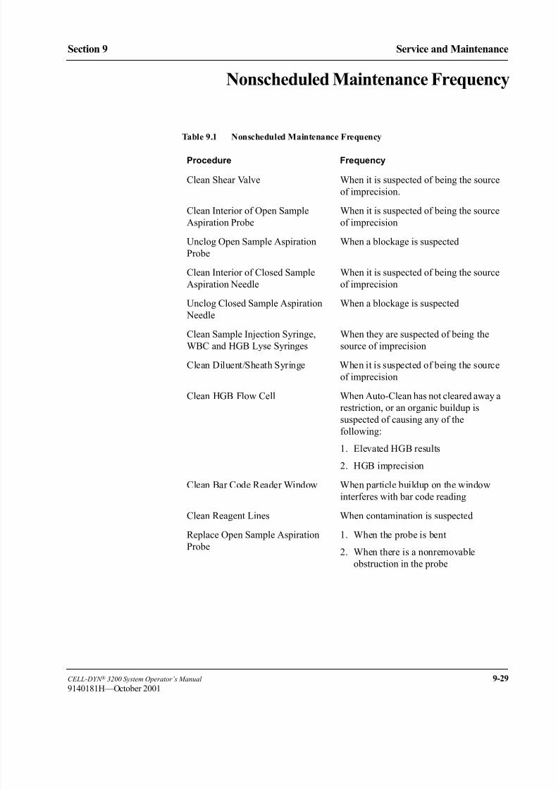
8/21/2019 Equ22-14 CellDyn3200 Op Man
http://slidepdf.com/reader/full/equ22-14-celldyn3200-op-man 405/690
CELL-DYN ® 3200 System Operator’s Manual 9-29
9140181H—October 2001
Section 9 Service and Maintenance
Nonscheduled Maintenance Frequency
Table 9.1 Nonscheduled Maintenance Frequency
Procedure Frequency
Clean Shear Valve When it is suspected of being the source
of imprecision.
Clean Interior of Open Sample
Aspiration Probe
When it is suspected of being the source
of imprecision
Unclog Open Sample Aspiration
Probe
When a blockage is suspected
Clean Interior of Closed SampleAspiration Needle When it is suspected of being the sourceof imprecision
Unclog Closed Sample Aspiration
Needle
When a blockage is suspected
Clean Sample Injection Syringe,
WBC and HGB Lyse Syringes
When they are suspected of being the
source of imprecision
Clean Diluent/Sheath Syringe When it is suspected of being the source
of imprecision
Clean HGB Flow Cell When Auto-Clean has not cleared away a
restriction, or an organic buildup is
suspected of causing any of the
following:
1. Elevated HGB results
2. HGB imprecision
Clean Bar Code Reader Window When particle buildup on the window
interferes with bar code reading
Clean Reagent Lines When contamination is suspected
Replace Open Sample Aspiration
Probe
1. When the probe is bent
2. When there is a nonremovableobstruction in the probe
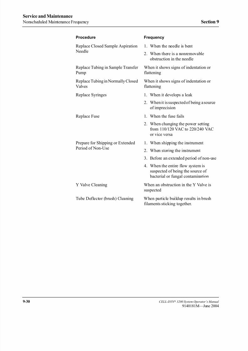
8/21/2019 Equ22-14 CellDyn3200 Op Man
http://slidepdf.com/reader/full/equ22-14-celldyn3200-op-man 406/690
9-30 CELL-DYN ® 3200 System Operator’s Manual
9140181M—June 2004
Service and Maintenance
Nonscheduled Maintenance Frequency Section 9
Replace Closed Sample Aspiration
Needle
1. When the needle is bent
2. When there is a nonremovable
obstruction in the needle
Replace Tubing in Sample Transfer
Pump
When it shows signs of indentation or
flattening
Replace Tubing in Normally Closed
Valves
When it shows signs of indentation or
flattening
Replace Syringes 1. When it develops a leak
2. When it is suspected of being a source
of imprecision
Replace Fuse 1. When the fuse fails
2. When changing the power settingfrom 110/120 VAC to 220/240 VAC
or vice versa
Prepare for Shipping or Extended
Period of Non-Use
1. When shipping the instrument
2. When storing the instrument
3. Before an extended period of non-use
4. When the entire flow system is
suspected of being the source of
bacterial or fungal contamination
Y Valve Cleaning When an obstruction in the Y Valve issuspected
Tube Deflector (brush) Cleaning When particle buildup results in brush
filaments sticking together.
Procedure Frequency
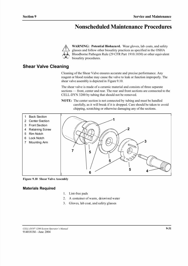
8/21/2019 Equ22-14 CellDyn3200 Op Man
http://slidepdf.com/reader/full/equ22-14-celldyn3200-op-man 407/690
CELL-DYN ® 3200 System Operator’s Manual 9-31
9140181M—June 2004
Section 9 Service and Maintenance
Nonscheduled Maintenance Procedures
WARNING: Potential Biohazard. Wear gloves, lab coats, and safetyglasses and follow other biosafety practices as specified in the OSHA
Bloodborne Pathogen Rule (29 CFR Part 1910.1030) or other equivalent
biosafety procedures.
Shear Valve Cleaning
Cleaning of the Shear Valve ensures accurate and precise performance. Any
reagent or blood residue may cause the valve to leak or function improperly. The
shear valve assembly is depicted in Figure 9.10.
The shear valve is made of a ceramic material and consists of three separate
sections — front, center and rear. The rear and front sections are connected to the
CELL-DYN 3200 by tubing that should not be removed.
NOTE: The center section is not connected by tubing and must be handled
carefully, as it will break if it is dropped. Care should be taken to avoid
chipping, scratching or otherwise damaging any of the sections.
Figure 9.10 Shear Valve Assembly
Materials Required
1. Lint-free pads
2. A container of warm, deionized water
3. Gloves, lab coat, and safety glasses
1 Back Section
2 Center Section
3 Front Section
4 Retaining Screw
5 Rim Notch
6 Lock Notch
7 Mounting Arm
1
2
3
46
5
7 5
5

8/21/2019 Equ22-14 CellDyn3200 Op Man
http://slidepdf.com/reader/full/equ22-14-celldyn3200-op-man 408/690
9-32 CELL-DYN ® 3200 System Operator’s Manual
9140181M—June 2004
Service and Maintenance
Nonscheduled Maintenance Procedures Section 9
Procedure
1. Pull the Tower Cover up and off the instrument (Tower Door on the CS model
must be open).
2. In the MAIN MENU, press [SPECIAL PROTOCOLS] followed by [CLEAN/RESSHEAR VAL] and [CLEAN SHEAR VAL]. This prepares the Shear Valve for
removal and puts the Analyzer into the NOT READY mode.
3. Place a clean gauze pad on the shelf in front of the Shear Valve.
4. Turn the Shear Valve Retaining Screw counterclockwise until it can be
removed. (Refer to Figure 9.10.)
5. Pull the front section forward until it is free of the mounting arm. Place the
front section with its attached tubes on the clean gauze pad.
6. Pull the center section forward until it is free of the mounting arm. Keep the
rear section in place.
NOTE: Be careful to keep a firm grip on the center section, as it is not
attached to the front or back sections and it may break or crack if
dropped.7. Place the center section in a container of warm water and allow it to soak for
the remainder of the cleaning procedure.
NOTE: Do not soak the center section in bleach because the bleach may
damage the ceramic.
8. Clean the mounting arm with a lint-free pad dampened with warm water to
remove any blood or residue. Wipe the guide dry.
9. Pull out the rear section of the Shear Valve and wipe the inner surface with a
lint-free pad dampened with warm water. Use care to avoid scratching the
inner surface. Do Not Dry.
NOTE: Hold the section by the edges to avoid getting fingerprints on theinner surface.
10. Align the lock notch of the rear section with the mounting guide. Carefully
slide this section back onto the mounting arm as far as it will go. Avoid
crimping any of the attached tubing.
11. Remove the center section from the warm water. Do Not Dry.
12. Place the center section aside on a clean gauze. Use care to avoid scratching
the surfaces.
13. View each surface under reflective light to confirm that it is clean, and free
of lint and fingerprints.

8/21/2019 Equ22-14 CellDyn3200 Op Man
http://slidepdf.com/reader/full/equ22-14-celldyn3200-op-man 409/690
CELL-DYN ® 3200 System Operator’s Manual 9-33
9140181M—June 2004
Section 9 Service and Maintenance
14. Align the lock notch of the center section with the mounting guide. (Lock
notch faces the mounting guide, smaller rim notch faces down.) Carefully
slide this section back onto the mounting arm until it is flush with the rear
section. (Refer to Figure 9.10.)
CAUTION: Results may be affected if the center section is installed back-
wards. Be certain the rim notch faces down.
15. Wipe the inner surface of the front section with a lint-free pad dampened with
warm water. Use care to avoid scratching the inner surface. Do not dry.
NOTE: Hold the section by the edges to avoid getting fingerprints on the
inner surfaces.
16. Align the lock notch of the front section with the mounting guide. A pin on
the inner rim should align with the groove on the mounting arm. Carefully
slide this section back until it touches the center section.
17. Firmly hold the three valve sections together and replace the Shear Valve
Retaining Screw. Turn the screw clockwise until it stops.
18. Remove any cleaning materials (such as gauze pads) that may have been left
on the instrument.
19. Press [RESTORE SHEAR VAL] to return the Shear Valve to its operating
position and to return the instrument to the READY state.
20. Replace the Tower Cover (Tower Door on the CS model must be open).
21. Press [RETURN] followed by [MAIN] and [RUN] to display the RUN screen.
22. Run at least five background counts to rinse the system. Check that the
background counts are acceptable before running controls or patient samples.
If the counts are unacceptable, troubleshoot accordingly (refer to Section 10:
Troubleshooting and Diagnostics; Subsection: Troubleshooting Guide).
23. Record this maintenance in your maintenance log.
Open Sample Probe Interior Cleaning
The Open Sample Aspiration Probe is thoroughly cleaned whenever the Auto-
Clean cycle is performed. However, additional cleaning may be required from time
to time. The probe may be cleaned manually, as described below.
Materials Required
1. Gloves, lab coat, and safety glasses
2. Syringe (10 cc or larger) with at least 3" of 1/32" silicone tubing attached to
the tip
3. Small needle-nose pliers or similar tool
4. Small beaker or container
5. Deionized water
6. Cleaning solution (0.5% sodium hypochlorite solution). See the formula for
mixing this solution under Decontamination Procedures earlier in this
section.

8/21/2019 Equ22-14 CellDyn3200 Op Man
http://slidepdf.com/reader/full/equ22-14-celldyn3200-op-man 410/690
9-34 CELL-DYN ® 3200 System Operator’s Manual
9140181H—October 2001
Service and Maintenance
Nonscheduled Maintenance Procedures Section 9
Procedure
WARNING: Potential Biohazard. The probe is sharp and potentially
contaminated with infectious material. Avoid contact with tip of probe.
1. In the MAIN MENU, press [SPECIAL PROTOCOLS] followed by [DIS/ENAB ANALYZER] and [DISABLE ANALYZER].
2. Locate the tubing attached to the top of the Open Sample Probe. (Refer to
Figure 9.11.) Place a small beaker or container under the probe to catch the
rinse solution. (Hint: Attach one end of a length of 1/32” tubing to the
aspiration end of the probe and place the other end of the tubing in the beaker
to prevent splashing.)
Figure 9.11 Open Sample Probe Assembly
3. Hold the probe firmly with one hand and with the other hand use the pliers to
carefully work the tubing up and off the top of the probe.
4. Use a syringe with 1/32" (internal diameter) tubing attached. Fill the syringe
with the cleaning solution prepared earlier. Attach the tubing connected to the
syringe onto the top of the probe and inject the solution to flush the probe.
1 Probe Tubing
2 Probe Top
3 Wash Block
1
2
3

8/21/2019 Equ22-14 CellDyn3200 Op Man
http://slidepdf.com/reader/full/equ22-14-celldyn3200-op-man 411/690
CELL-DYN ® 3200 System Operator’s Manual 9-35
9140181H—October 2001
Section 9 Service and Maintenance
5. Fill the same syringe with deionized water and inject the water into the probe
from the top to rinse the probe. Repeat the procedure three times to
thoroughly rinse the probe.
NOTE: Empty the container or tube between rinses as necessary.
6. Hold the probe steady and reattach the tubing over the top. Use the pliers to
carefully work the tubing down the probe. Be sure the tubing is firmly seated
on the probe. (Remove any tubing that may have been placed on the
aspiration end of the probe.)
NOTE: Wetting the top portion of the probe will allow the tubing to slide
more easily.
7. Be sure to remove the beaker containing the rinse solution from the
instrument.
8. Press [ENABLE ANALYZER] followed by [RETURN] and [MAIN] to return to the
MAIN MENU.
9. Press [RUN] followed by [SPECIMEN TYPE] and [BACKGROUND].
10. Run at least three background counts to rinse the system. Check that the background counts are acceptable before running controls or patient samples.
If the counts are unacceptable, troubleshoot accordingly (refer to Section 10:
Troubleshooting and Diagnostics; Subsection: Troubleshooting Guide).
11. Record this maintenance in your maintenance log.

8/21/2019 Equ22-14 CellDyn3200 Op Man
http://slidepdf.com/reader/full/equ22-14-celldyn3200-op-man 412/690
9-36 CELL-DYN ® 3200 System Operator’s Manual
9140181H—October 2001
Service and Maintenance
Nonscheduled Maintenance Procedures Section 9
Unclogging the Open Sample Aspiration Probe
If a blockage is suspected, it may be cleared using the procedure described above
in Open Sample Probe Interior Cleaning .
Closed Sample Needle Interior CleaningThe Aspiration Needle in the Tower Module should be cleaned regularly to remove
protein buildup or debris and reduce the possibility of a blockage. In addition to the
Aspiration Needle Cleaning in Daily Maintenance Procedures, use the steps
described below for cleaning the needle in the Tower Module.
Materials Required
1. Gloves, lab coat, and safety glasses
2. Syringe (10 cc or larger) with at least 3" of 1/32" (internal diameter) silicone
tubing attached to the tip
3. Small needle-nose pliers or similar tool
4. Beaker or container
5. Deionized water
6. Cleaning solution (0.5% sodium hypochlorite solution). See the formula for
mixing this solution under Decontamination Procedures earlier in this
section.
Procedure
WARNING: Potential Biohazard. The sample needle is sharp and
potentially contaminated with infectious material. Avoid contact with the
tip of the needle.
1. In the MAIN MENU, press [SPECIAL PROTOCOLS] followed by [DIS/ENAB ANALYZER] and [DISABLE ANALYZER].
2. Pull the tower cover up and off the instrument. (Tower Door on the CS model
must be open).
3. Locate the Aspiration Tubing and Vent Tubing attached to the top of the
Closed Sample Aspiration Needle. (Refer to Figure 9.12.)
NOTE: The Aspiration Needle consists of two separate needles joined
together, one for venting and one for aspiration. The vent needle is
the shorter of the two and faces the instrument. Note that the tubing
attached to the opening at the top of the vent needle leads to a vent
chamber on the left side of the Tower Module, while the tubing
attached to the opening at the top of the aspiration needle leads to
Y valve located between the Shear Valve and the Open Sample
Probe.
4. Hold the needle firmly with one hand and with the other hand use the pliers
to carefully work the Aspiration Tubing and Vent Tubing up and off the top
of the needle.
5. Loosen the Thumb Screw at the top of the Needle Mounting Assembly and
remove the clip holding the needle to the assembly.

8/21/2019 Equ22-14 CellDyn3200 Op Man
http://slidepdf.com/reader/full/equ22-14-celldyn3200-op-man 413/690
CELL-DYN ® 3200 System Operator’s Manual 9-37
9140181M—June 2004
Section 9 Service and Maintenance
6. Carefully pull the top of the needle forward until the flange clears the slot in
the bracket. Lift the needle up and out of the Wash Block and place it in the
beaker or container.
Figure 9.12 Closed Sample Needle
7. Use a syringe with 1/32" (internal diameter) tubing attached. Fill the syringe
with the cleaning solution prepared earlier. Attach the tubing connected to the
syringe onto the top of the Aspiration Needle and inject the solution to flush
the needle.
8. Fill the same syringe with deionized water and inject the water into the needlefrom the top to rinse it. Repeat the procedure three times to thoroughly rinse
the needle.
NOTE: Empty the container between rinses as necessary.
9. Repeat steps 7 and 8 to flush Vent Needle the same way.
1 Holding Clip
2 Aspiration Tubing3 Vent Tubing
4 Needle Top*
5 Vent Needle (shorter)
6 Aspiration Needle
(longer)
7 Wash Block
8 Needle Mounting
Assembly
9 Thumb Screw (with
spring)
*port faces instrument
1
2
3 48
9
5
67

8/21/2019 Equ22-14 CellDyn3200 Op Man
http://slidepdf.com/reader/full/equ22-14-celldyn3200-op-man 414/690
9-38 CELL-DYN ® 3200 System Operator’s Manual
9140181H—October 2001
Service and Maintenance
Nonscheduled Maintenance Procedures Section 9
10. Place the needle back into the Wash Block, making sure the shorter part (vent
needle) faces the instrument, and place the flange into its slot in the top
bracket.
11. Reinstall the clip over the top of the needle and tighten the thumb screw.
12. Attach the vent tubing to the vent section of the needle and the aspiration
tubing to the aspiration section.
NOTE: It is important that the tubing be attached correctly. (Refer to
Figure 9.12.)
NOTE: Wetting the top portion of the needle will allow the tubing to slide
more easily.
13. Reattach the Tower Cover (Tower Door on the CS model must be open) and
press into place.
14. Press [ENABLE ANALYZER] followed by [RETURN] and [MAIN] to return to the
MAIN MENU.
15. Run at least three background counts to rinse the system. Check that the
background counts are acceptable before running controls or patient samples.If the counts are unacceptable, troubleshoot accordingly (refer to Section 10:
Troubleshooting and Diagnostics; Subsection: Troubleshooting Guide).
16. Record this maintenance in your maintenance log.

8/21/2019 Equ22-14 CellDyn3200 Op Man
http://slidepdf.com/reader/full/equ22-14-celldyn3200-op-man 415/690
CELL-DYN ® 3200 System Operator’s Manual 9-39
9140181H—October 2001
Section 9 Service and Maintenance
Unclogging the Closed Sample Aspiration Needle
If a blockage is suspected, it may be cleared using the procedure described above
in Closed Sample Needle Interior Cleaning .
Syringe CleaningThere are two syringe assemblies, each containing two syringes, on the Flow Panel
of the CELL-DYN 3200 system. The syringe assemblies are depicted in Figure
9.13.
Syringes on the CELL-DYN 3200 System should be cleaned only as necessary one
at a time to ensure that each syringe is replaced in the correct position. Replace
each syringe after it is cleaned and then remove the next one to be cleaned.
Figure 9.13 Syringe Assemblies
1 Sample Injection
Syringe
2 HGB Lyse Syringe
3 WBC Lyse Syringe4 Diluent/Sheath
Syringe
5 Holding Blocks
1
2
3
4
5

8/21/2019 Equ22-14 CellDyn3200 Op Man
http://slidepdf.com/reader/full/equ22-14-celldyn3200-op-man 416/690
9-40 CELL-DYN ® 3200 System Operator’s Manual
9140181M—June 2004
Service and Maintenance
Nonscheduled Maintenance Procedures Section 9
Materials Required
1. A large container filled with approximately 500 mL of warm, deionized
water
2. Lint-free pads
3. Distilled water
4. Small container of each reagent to refill the clean syringes
5. Phillips-head screwdriver (#2)
6. Flat-head screwdriver
Disabling the Analyzer
1. In the MAIN MENU, press [SPECIAL PROTOCOLS] followed by [DIS/ENAB ANALYZER] and [DISABLE ANALYZER].
2. To gain access to the syringe assemblies, open Left and Right Front Covers
as follows. Gently pull on cover using hand hold and swing door open about
30-45 degrees. Lift door fully upward from bottom area closest to door hinge
bracket, then rotate door fully open so lift and hold feature on upper doorhinge mechanism can be engaged. Lower door gently. Gently pull the Tower
Cover and lift the cover up and off the instrument. (Tower Door on the CS
model must be open.)
a. On the CS model, remove the four Phillips-head screws holding the Front
Skirt to the instrument and remove the skirt.
b. The skirt on the SL model has two removable sections adjacent to the
Flow Panel. Remove the section on the right side of the Flow Panel by
lifting it up and off its holding pins.
For easy access to the Flow Panel, the Sample Loader on the SL Model can
be pulled away from the analyzer by performing the following optional steps:
NOTE: Instruments with serial number 59965AF and below do not have
the hardware configuration to support this option.
1. Remove the Phillips-head screw that holds the Sample Loader Tower
in place on the Front Panel. Refer to the following Figure 9.14.
Figure 9.14 Sample Loader Tower
2. Loosen the flat-head screws, two on each side of the instrument.
Refer to the following Figure 9.15.

8/21/2019 Equ22-14 CellDyn3200 Op Man
http://slidepdf.com/reader/full/equ22-14-celldyn3200-op-man 417/690
CELL-DYN ® 3200 System Operator’s Manual 9-41
9140181H—October 2001
Section 9 Service and Maintenance
Figure 9.15 Sample Loader Mounting Screws
3. Carefully lift and pull the Sample Loader away from the instrument
approximately 2-3 inches.
4. Push the Sample Loader down to lock it in to place.
Figure 9.16 Sample Injection Syringe Removal
1 Tube Fitting
2 Sample Injection
Syringe
3 Double Collar
4 Base
5 Luer Lock
5
1
2
34
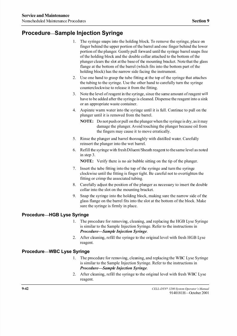
8/21/2019 Equ22-14 CellDyn3200 Op Man
http://slidepdf.com/reader/full/equ22-14-celldyn3200-op-man 418/690
9-42 CELL-DYN ® 3200 System Operator’s Manual
9140181H—October 2001
Service and Maintenance
Nonscheduled Maintenance Procedures Section 9
Procedure — Sample Injection Syringe
1. The syringe snaps into the holding block. To remove the syringe, place on
finger behind the upper portion of the barrel and one finger behind the lower
portion of the plunger. Gently pull forward until the syringe barrel snaps free
of the holding block and the double collar attached to the bottom of the
plunger clears the slot at the base of the mounting bracket. Note that the glass
flange at the bottom of the barrel (which fits into the bottom part of the
holding block) has the narrow side facing the instrument.
2. Use one hand to grasp the tube fitting at the top of the syringe that attaches
the tubing to the syringe. Use the other hand to carefully turn the syringe
counterclockwise to release it from the fitting.
3. Note the level of reagent in the syringe, since the same amount of reagent will
have to be added after the syringe is cleaned. Dispense the reagent into a sink
or an appropriate waste container.
4. Aspirate warm water into the syringe until it is full. Continue to pull on the
plunger until it is removed from the barrel.
NOTE: Do not push or pull on the plunger when the syringe is dry, as it may
damage the plunger. Avoid touching the plunger because oil from
the fingers may cause it to move erratically.
5. Rinse the plunger and barrel thoroughly with distilled water. Carefully
reinsert the plunger into the wet barrel.
6. Refill the syringe with fresh Diluent/Sheath reagent to the same level as noted
in step 3.
NOTE: Verify there is no air bubble sitting on the tip of the plunger.
7. Insert the tube fitting into the top of the syringe and turn the syringe
clockwise until the fitting is finger tight. Be careful not to overtighten the
fitting or crimp the associated tubing.
8. Carefully adjust the position of the plunger as necessary to insert the double
collar into the slot on the mounting bracket.
9. Snap the syringe into the holding block, making sure the narrow side of the
glass flange on the barrel fits into the slot at the bottom of the block. Make
sure the syringe is firmly in place.
Procedure — HGB Lyse Syringe
1. The procedure for removing, cleaning, and replacing the HGB Lyse Syringe
is similar to the Sample Injection Syringe. Refer to the instructions in
Procedure—Sample Injection Syringe.
2. After cleaning, refill the syringe to the original level with fresh HGB Lyse
reagent.
Procedure — WBC Lyse Syringe
1. The procedure for removing, cleaning, and replacing the WBC Lyse Syringe
is similar to the Sample Injection Syringe. Refer to the instructions in
Procedure—Sample Injection Syringe.
2. After cleaning, refill the syringe to the original level with fresh WBC Lyse
reagent.
8/21/2019 Equ22-14 CellDyn3200 Op Man
http://slidepdf.com/reader/full/equ22-14-celldyn3200-op-man 419/690
CELL-DYN ® 3200 System Operator’s Manual 9-43
9140181H—October 2001
Section 9 Service and Maintenance
Procedure — Diluent/Sheath Syringe
1. Locate the Diluent/Sheath Syringe (refer to Figure 9.17). Note that the plastic
barrel of this syringe has four vertical edges, two of which fit into grooves on
the holding block, and a circular plastic flange which also fits into a groove
on the holding block.
2. Grasp the plastic tube fitting at the top of the syringe that attaches to the Luer
Lock. Carefully turn the Luer Lock on the syringe clockwise to release it
from the fitting. Use the lint-free pads to absorb excess reagent.
3. Grasp the syringe barrel below the Luer Lock with one hand. With the other
hand, grasp the syringe plunger below the metal band. Pull and twist one side
of the syringe to remove it from the snap-in holding block.
4. Note the liquid level in the syringe so that it can be refilled after cleaning to
approximately the same level.
5. Dispense the reagent into a sink or other appropriate waste container.
NOTE: Do not pull the plunger out of the barrel. Also, do not push or pull
on the plunger when the syringe is dry, as it may damage the
plunger. Avoid touching the plunger, because oil from the fingers
may cause it to move erratically.
6. Immerse the tip of the syringe in the container of deionized water.
7. Aspirate deionized water into the syringe until it is full, and dispense the
water into a sink or other appropriate waste container. Repeat this step several
times to thoroughly rinse the syringe.
8. Refill the syringe with Diluent/Sheath reagent to the level noted in Step 4.

8/21/2019 Equ22-14 CellDyn3200 Op Man
http://slidepdf.com/reader/full/equ22-14-celldyn3200-op-man 420/690
9-44 CELL-DYN ® 3200 System Operator’s Manual
9140181H—October 2001
Service and Maintenance
Nonscheduled Maintenance Procedures Section 9
Figure 9.17 Diluent/Sheath Syringe Replacement
9. Insert the double collar on the plunger into the slot on the mounting bracket
and line up the circular flange on the barrel with the slot on the holding block.
10. Insert one of the vertical edges on the barrel into a side groove on the holding
block and carefully twist the barrel until the other side snaps into place. Make
sure the syringe is firmly in place.
11. Place the tube fitting into the Luer Lock and turn the lock counterclockwise
until the fitting is finger tight. Be careful not to overtighten the fitting or
crimp the associated tubing.
1 Tube Fitting
2 Luer Lock
3 Holding Block
4 Diluent/Sheath
Syringe
5 Double Collar 1
2
3
4
5
8/21/2019 Equ22-14 CellDyn3200 Op Man
http://slidepdf.com/reader/full/equ22-14-celldyn3200-op-man 421/690
CELL-DYN ® 3200 System Operator’s Manual 9-45
9140181L—July 2003
Section 9 Service and Maintenance
Enabling the Analyzer
When all syringes have been re-installed, do the following:
1. Press [ENABLE ANALYZER] followed by [RETURN], [MAIN] and [RUN] to return to the RUN screen.
2. Run several background counts in the Open Mode and observe the action ofthe syringes during the cycle. The plungers should move smoothly up and
down and should not leak.
3. After the operation of all the syringes has been verified, do the following:
a. On the CS model, reattach the Front Skirt using the four Phillips-head
screws. Do not pinch the tubing at the bottom.
b. On the SL model, align the removable right side skirt panel over its
holding pins and slide down. If the Sample Loader has been pulled away
as described in Subsection: Disabling the Analyzer (optional steps),
perform the following steps:
1. Carefully lift and push the Sample Loader toward the instrument.
2. Push the Sample loader down to lock it in place.
3. Reinstall the Phillips-head screw that holds the Sample loader Tower
in place on the Front Panel. Do not pinch any tubing between the
Tower and the Flow Panel. Refer to Figure 9.14.
4. Tighten the flat head screws: two on each side of the instrument.
Refer to Figure 9.15.
c. Reattach the Tower Cover (Tower Door on the CS model must be open)
and press into place.
d. Close the Left and Right Front Covers.
4. Run at least three background counts. Check that the background counts are
acceptable before running controls or patient samples. If the counts areunacceptable, troubleshoot accordingly (refer to Section 10:
Troubleshooting and Diagnostics; Subsection: Troubleshooting Guide).
5. Record this maintenance in your maintenance log.
HGB Flow Cell Manual Cleaning Procedure
NOTE: This is not a routine cleaning/maintenance procedure. It should only be
performed if routine methods fail or at the request of Abbott Customer
Service.
Under normal circumstances, the Auto-Clean cycle is sufficient to ensure the
cleanliness of the HGB Flow Cell. If the Auto-Clean cycle fails to adequately clean
the flow cell, the procedure described below may be used.

8/21/2019 Equ22-14 CellDyn3200 Op Man
http://slidepdf.com/reader/full/equ22-14-celldyn3200-op-man 422/690
9-46 CELL-DYN ® 3200 System Operator’s Manual
9140181K—July 2002
Service and Maintenance
Nonscheduled Maintenance Procedures Section 9
Figure 9.18 HGB Flow Cell Access Tubing
Materials Required
1. Cleaning solution (1.25% sodium hypochlorite solution). See the formula for
mixing this solution under Decontamination Procedures earlier in this
section.
2. 10 mL syringe
3. Gloves, lab coat, and safety glasses
4. Deionized water
Procedure
1. In the MAIN MENU, press [SPECIAL PROTOCOLS] followed by [DIS/ENABLE ANALYZER] and [DISABLE ANALYZER] to disable the Analyzer.
2. Gently pull on the hand hold of the right Front Cover to swing the cover open.
Pull the Tower Cover up and off the instrument (Tower Door on the CS model
must be open). Locate the HGB Flow Cell. (Refer to Figure 9.4.)
3. Remove the plastic drip pan under the Shear Valve by sliding it up and off the
support stand.
4. Fill the syringe with the bleach solution.
1 Solenoid 24
2 Tube Fitting
3 Shear Valve
1
2
3

8/21/2019 Equ22-14 CellDyn3200 Op Man
http://slidepdf.com/reader/full/equ22-14-celldyn3200-op-man 423/690
CELL-DYN ® 3200 System Operator’s Manual 9-47
9140181H—October 2001
Section 9 Service and Maintenance
5. Locate the tubing just above solenoid #24 that attaches to the HGB Flow Cell.
(Refer to the previous figure.) Attach a hemostat to the tubing between the
fitting and the HGB Flow Cell.
6. Disconnect the tubing from the fitting and insert the syringe. Remove the
hemostat. Dispense the cleaning solution into the flow cell.
7. Allow the bleach solution to remain in the flow cell for 5 minutes.
8. When the time has elapsed, aspirate the solution back into the syringe and
reattach the hemostat.
9. Reconnect the tubing and remove the hemostat.
10. Reinsert the plastic drip pan by aligning the grooves on the pan with the
upright support arms and sliding the pan down until it rests on the support.
11. Reattach the Tower Cover (Tower Door on the CS model must be open) and
press into place. Close Right Front Cover.
12. Press [ENABLE ANALYZER] followed by [RETURN] and [MAIN] and [RUN].
13. Run at least three background counts to rinse the system. Check that the
background counts are acceptable before running controls or patient samples.If the counts are unacceptable, troubleshoot accordingly (refer to Section 10:
Troubleshooting and Diagnostics; Subsection: Troubleshooting Guide).
14. Record this maintenance in your maintenance log.
Bar Code Reader Window Cleaning
The cleaning procedure is similar for the SL and CS models even though the
location of the Bar Code Reader is different.
Materials Required
1. Gloves, lab coat, and safety glasses
2. Applicator swabs (non-sterile)
3. Microscope lens tissues
4. Isopropyl alcohol, lens cleaner, or deionized water
Procedure
1. In the MAIN MENU, press [SPECIAL PROTOCOLS] followed by [DIS/ENAB ANALYZER] and [DISABLE ANALYZER].
2. Take three applicator swabs and wrap a lens tissue around each swab.
3. Moisten one of the wrapped swabs in isopropyl alcohol, lens cleaner, or
deionized water.
4. Locate the Bar Code Reader Window.
5. Wipe the window with the moistened swab. Using one of the dry wrapped
swabs, wipe the window dry. Use the second dry swab if necessary.
6. Visually inspect the window to ensure that blood, debris, and smudges have
been removed.
7. Press the [ENABLE ANALYZER] key to bring the system to the READY state.
Press [RETURN] followed by [MAIN] and [RUN] to return to the RUN screen.

8/21/2019 Equ22-14 CellDyn3200 Op Man
http://slidepdf.com/reader/full/equ22-14-celldyn3200-op-man 424/690
9-48 CELL-DYN ® 3200 System Operator’s Manual
9140181H—October 2001
Service and Maintenance
Nonscheduled Maintenance Procedures Section 9
Reagent Line Cleaning
The reagent lines should be cleaned if contamination is suspected. To clean the
lines, refer to steps 1–4 in Preparation for Shipping or Extended Period of
Non-Use later in this section.
Open Sample Probe Replacement
Materials Required
1. Gloves, lab coat, and safety glasses
2. Replacement probe
3. 7/64" Allen wrench
4. Small needle-nose pliers or similar tool
Procedure
1. In the MAIN MENU, press [SPECIAL PROTOCOLS] followed by [DIS/ENAB ANALYZER] and [DISABLE ANALYZER].
2. Gently pull on the hand hold of the Right Front Cover and swing the cover
open to access the right side of the Flow Panel. Remove Tower Cover.
3. Locate the tubing attached to the top of the Open Sample Probe. (Refer to
Figure 9.19.) Hold the probe firmly with one hand and with the other hand
use the pliers to carefully work the tubing up and off the top of the probe.
4. Using the Allen wrench, remove the two hex nuts holding the Probe Bracket
Arm to the Bracket Support Arm on the Probe Assembly Frame.
5. Pull the probe up and out of the Wash Block.
6. Insert the new probe into the Wash Block.
7. Place the Probe Bracket Arm on top of the Bracket Support Arm. Align theholes in the bracket arm to the holes in the Probe Assembly Frame. Insert and
tighten the two hex nuts using the Allen wrench.
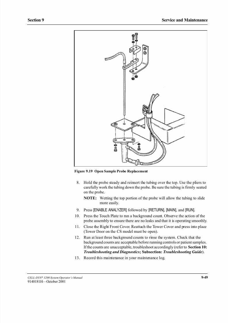
8/21/2019 Equ22-14 CellDyn3200 Op Man
http://slidepdf.com/reader/full/equ22-14-celldyn3200-op-man 425/690
CELL-DYN ® 3200 System Operator’s Manual 9-49
9140181H—October 2001
Section 9 Service and Maintenance
Figure 9.19 Open Sample Probe Replacement
8. Hold the probe steady and reinsert the tubing over the top. Use the pliers to
carefully work the tubing down the probe. Be sure the tubing is firmly seated
on the probe.
NOTE: Wetting the top portion of the probe will allow the tubing to slide
more easily.
9. Press [ENABLE ANALYZER] followed by [RETURN], [MAIN], and [RUN].
10. Press the Touch Plate to run a background count. Observe the action of the
probe assembly to ensure there are no leaks and that it is operating smoothly.
11. Close the Right Front Cover. Reattach the Tower Cover and press into place(Tower Door on the CS model must be open).
12. Run at least three background counts to rinse the system. Check that the
background counts are acceptable before running controls or patient samples.
If the counts are unacceptable, troubleshoot accordingly (refer to Section 10:
Troubleshooting and Diagnostics; Subsection: Troubleshooting Guide).
13. Record this maintenance in your maintenance log.

8/21/2019 Equ22-14 CellDyn3200 Op Man
http://slidepdf.com/reader/full/equ22-14-celldyn3200-op-man 426/690
9-50 CELL-DYN ® 3200 System Operator’s Manual
9140181H—October 2001
Service and Maintenance
Nonscheduled Maintenance Procedures Section 9
Closed Sample Needle Replacement
If the Closed Sample Aspiration Needle becomes bent or becomes clogged (and
cleaning does not remove the blockage), the needle should be replaced.
Materials Required1. Gloves, lab coat, and safety glasses
2. Replacement needle
3. Phillips-head screwdriver (#2)
4. Small needle-nose pliers or similar tool
Procedure
WARNING: Potential Biohazard. The sample needle is sharp and
potentially contaminated with infectious material. Avoid contact with tip of
needle.
1. In the MAIN MENU, press [SPECIAL PROTOCOLS] followed by [DIS/ENAB ANALYZER] and [DISABLE ANALYZER].
2. Pull the Tower cover up and off the instrument (Tower Door on the CS model
must be open).
3. Locate the Aspiration Needle.
NOTE: The Aspiration Needle consists of two separate needles joined
together, one for venting and one for aspiration. (Refer to Figure
9.20.) The vent needle is the shorter of the two and faces the
instrument. Note that the tubing attached to the opening at the top
of the vent needle leads to a vent chamber on the left side of the
Tower Module, while the tubing attached to the opening at the top
of the aspiration needle leads to Y valve located between the ShearValve and the Open Sample Probe.

8/21/2019 Equ22-14 CellDyn3200 Op Man
http://slidepdf.com/reader/full/equ22-14-celldyn3200-op-man 427/690
CELL-DYN ® 3200 System Operator’s Manual 9-51
9140181M—June 2004
Section 9 Service and Maintenance
Figure 9.20 Closed Sample Needle
4. Hold the needle firmly with one hand and with the other hand use the pliers
to carefully work the tubing up and off the top of both ends of the needle.
5. Loosen the Thumb Screw at the top of the Needle Mounting Assembly and
remove the clip holding the needle to the assembly.
6. Carefully pull the top of the needle forward until the flange clears the slot in
the bracket. Lift the needle up and out of the Wash Block.
7. Place the new needle into the Wash Block, making sure the shorter part
(venting needle) faces the instrument, and place the flange into its slot in thetop bracket.
8. Reinstall the clip over the top of the needle and tighten the Thumb Screw.
9. Attach the vent tubing to the vent section of the needle and the aspiration
tubing to the aspiration section.
NOTE: It is important that the tubing be attached correctly.
NOTE: Wetting the top portion of the needle will allow the tubing to slide
more easily.
1 Holding Clip
2 Aspiration Tubing
3 Vent Tubing
4 Needle Top
5 Vent Needle (shorter)6 Aspiration Needle
(longer)
7 Wash Block
8 Needle Mounting
Assembly
9 Thumb Screw (with
spring)
1
2
3 48
9
5
6
7
8/21/2019 Equ22-14 CellDyn3200 Op Man
http://slidepdf.com/reader/full/equ22-14-celldyn3200-op-man 428/690
9-52 CELL-DYN ® 3200 System Operator’s Manual
9140181M—June 2004
Service and Maintenance
Nonscheduled Maintenance Procedures Section 9
10. Reattach the Tower Cover (Tower Door on the CS model must be open) and
press into place.
11. Press [ENABLE ANALYZER] followed by [RETURN] and [MAIN] to return to the
MAIN MENU.
12. Run at least three background counts to rinse the system. Check that the
background counts are acceptable before running controls or patient samples.If the counts are unacceptable, troubleshoot accordingly (refer to Section 10:
Troubleshooting and Diagnostics; Subsection: Troubleshooting Guide).
13. Record this maintenance in your maintenance log.
Sample Transfer Pump Tubing Replacement
The tubing under the Sample Transfer Peristaltic Pump needs to be replaced on a
regular basis to ensure proper fluid movement through the instrument. This tubing
should be replaced at least every 2000 cycles. However, the frequency of
replacement depends on instrument use in each laboratory. The Sample Transfer
Pump is shown in Figure 9.6.
Materials Required
1. Sample Transfer Peristaltic Pump Tubing
2. Gloves, lab coat, and safety glasses
Procedure
1. In the MAIN MENU, press [SPECIAL PROTOCOLS] followed by [DIS/ENAB ANALYZER] and [DISABLE ANALYZER].
2. Gently pull on the hand hold of the Left Front Cover and swing the cover
open.
3. Locate the Sample Transfer Peristaltic Pump on the left side of the panel.
(Refer to Figure 9.4.)4. Hold the Pump Shoe away from the pump wheel and remove the tubing from
under the pump wheel by lifting the collars out of the metal brackets that hold
them. Remove the tubing completely out from under the pump wheel (Refer
to Figure 9.6)
5. Disconnect the tubing at the plastic connector.
6. Connect the new tubing to the plastic connector.
7. Place the collars on the ends of the pump tubing into the metal brackets as
shown in Figure 9.6. Hold the Pump Shoe open and insert the tubing back
under the pump rollers. Make sure the tubing is positioned in the center of the
rollers. When the tubing is centered, release the Pump Shoe.
8. Close the Left Front Cover.
9. Press [ENABLE ANALYZER] to bring the instrument to the READY state.
10. Press [RETURN] followed by [MAIN] and [RUN] to display the RUN screen.
11. Run at least three background counts to rinse the system. Check that the
background counts are acceptable before running controls or patient samples.
If the counts are unacceptable, troubleshoot accordingly (refer to Section 10:
Troubleshooting and Diagnostics; Subsection: Troubleshooting Guide).
12. Record this maintenance in your maintenance log.
8/21/2019 Equ22-14 CellDyn3200 Op Man
http://slidepdf.com/reader/full/equ22-14-celldyn3200-op-man 429/690
CELL-DYN ® 3200 System Operator’s Manual 9-53
9140181L—July 2003
Section 9 Service and Maintenance
Normally Closed Valve Tubing Replacement
Tubing in the Normally Closed Valves should be replaced when it shows signs of
indentation or flattening and is impeding the flow of fluid through the tubing.
Materials Required1. Valve Tubing (12 inches)
2. Gloves, lab coat, and safety glasses
3. Phillips-head screwdriver (#2)
4. Hemostats (2)
Procedure
1. In the MAIN MENU, press [SPECIAL PROTOCOLS] followed by [MORE]followed by [DAILY SHUTDOWN]. Wait until the instrument is in STANDBY,
then turn the power switch OFF.
2. Gently pull on the hand hold of the Right Front Cover and swing the cover
open.
3. Gently pull on the hand hold of the Left Front Cover and swing the cover
open.
4. Pull the Tower cover up and off the instrument (Tower Door on the CS model
must be open).
5. To gain access to the lower portion of the Flow Panel:
a. On the CS model, remove the four Phillips-head screws holding the Front
Skirt to the instrument and remove the skirt.
b. On the SL model, remove the section on the left side of the Flow Panel
by lifting it up and off the holding pins on the rear rail of the Sample
Loader.6. Locate all six Normally Closed Valves on the Flow Panel. (Refer to Figure
9.4.)
7. Use hemostats to clamp the tubing above and below the normally closed
valve tubing connectors to prevent leakage when the normally closed valve
tubing is replaced. Remove the tubing from each valve.
NOTE: On the SL model, space is limited between the inner edge of the
Sample Loader and the two normally closed values on the lower
left side of the Flow Panel. Use caution when accessing the tubing
in these two valves.
8. Pull the tubing from the connectors on either side as shown in Figure 9.21.

8/21/2019 Equ22-14 CellDyn3200 Op Man
http://slidepdf.com/reader/full/equ22-14-celldyn3200-op-man 430/690
9-54 CELL-DYN ® 3200 System Operator’s Manual
9140181M—June 2004
Service and Maintenance
Nonscheduled Maintenance Procedures Section 9
Figure 9.21 Tubing in Normally Closed Valve
9. Insert the new tubing section into both connectors. Make sure the tubing is
pushed all the way into the connectors.
10. Reinsert the tubing into the slot on the valves. Work the tubing firmly back
and forth until it is completely inserted into the valve and resting on the
bottom of the slot. Unless the tubing is securely seated, the flow system will
not function properly. Remove the hemostats.
11. Replace covers:
a. On the CS model, reattach the Front Skirt using the four Phillips-head
screws. Do not pinch the tubing at the bottom.
b. On the SL model, align the removable left side skirt panel over its
holding pins and slide down.
c. Close the Left and Right Front Covers. Reattach the Tower Cover and
press into place (Tower Door on the CS model must be open).
12. Turn the Power switch ON. Wait until the instrument is initialized, then press
[RUN] to prime the system and place it in READY state.
13. Run at least three background counts to rinse the system. Check that the background counts are acceptable before running controls or patient samples.
If the counts are unacceptable, troubleshoot accordingly (refer to Section 10:
Troubleshooting and Diagnostics; Subsection: Troubleshooting Guide).
14. Record this maintenance in your maintenance log.
1 Connectors
2 Tubing
3 Slot
4 Normally Closed Valve
1 24
3
8/21/2019 Equ22-14 CellDyn3200 Op Man
http://slidepdf.com/reader/full/equ22-14-celldyn3200-op-man 431/690
CELL-DYN ® 3200 System Operator’s Manual 9-55
9140181K—July 2002
Section 9 Service and Maintenance
Syringe Replacement
A syringe should be replaced under the following conditions:
1. There is evidence of leaking
2. It is suspected of being a source of imprecision.
Materials Required
1. Replacement syringe
2. Gloves, lab coat, and safety glasses
Procedure
1. The procedures for removing and installing the Sample Injection Syringe,
WBC Lyse Syringe, HGB Lyse Syringe, and Diluent/Sheath Syringe are
described earlier in this subsection.
2. After the old syringe has been removed, follow the instructions in Syringe
Cleaning to reinstall the new syringe and bring the Analyzer back to the
READY state.
Fuse Replacement
There are two conditions under which a fuse should be replaced:
1. If the fuse has failed, or
2. If the power setting is changed from 110/120 VAC to 220/240 VAC or vice
versa.
Materials Required
1. Replacement fuse (8-amp T (Slo-Blo) for instruments operating at110/120 VAC or 4-amp T (Slo-Blo) for instruments operating at
220/240 VAC)
2. Flathead screwdriver
Procedure
CAUTION: Electrical Hazard. Turn off the power to the instrument and
disconnect the power cord before removing any instrument panel that is
securely fastened in place by screws or prior to replacing fuses. Replace
only the externally accessible fuse located immediately above the power
cord connector on the rear of the instrument. Use replacement fuses only of
the specified type and electrical rating.
1. Turn the system OFF and disconnect the power cord. Locate the plastic fuse
holder on the Rear Panel. (Refer to Figure 9.22.)
2. With the system OFF, insert a flathead screwdriver into the notch on the fuse
holder.
3. Push in and turn the fuse holder counter clockwise to release the holder. Pull
the holder with the fuse completely out of its slot.
4. Pull the fuse to remove it from the holder. Check the fuse.

8/21/2019 Equ22-14 CellDyn3200 Op Man
http://slidepdf.com/reader/full/equ22-14-celldyn3200-op-man 432/690
9-56 CELL-DYN ® 3200 System Operator’s Manual
9140181L—July 2003
Service and Maintenance
Nonscheduled Maintenance Procedures Section 9
Figure 9.22 Fuse Replacement
5. If it has obviously failed, replace it. Note the amp reading on the fuse and be
sure you replace it with the correct fuse (8-amp or 4-amp).
NOTE: If the power setting is 110/120 VAC, use the 8-amp fuse. If the
power setting is 220/240 VAC, use the 4-amp fuse.
6. If you are not sure if the fuse has failed, replace it and see if the problem is
corrected.
7. To replace a fuse, insert the new fuse (either end) into the holder. Insert theholder (fuse first) all the way into the fuse slot.
8. Insert a flathead screwdriver into the notch on the fuse holder, push in, and
turn clockwise to tighten the fuse holder.
9. Reconnect the power cord and turn the system ON.
10. Record the maintenance in your maintenance log.
Preparation for Shipping or Extended Period of Non-Use
The Prepare For Shipping cycle must be run if the instrument will not be used for
two weeks or more. This cycle must also be run if:
a. The instrument will be shipped b. The instrument will be moved (for example, to a different location within
a laboratory) and movement will require detaching the reagent inlet
tubing.
1 Power Supply
2 Fuse Holder
3 Fuse Holder Notch1
2
3

8/21/2019 Equ22-14 CellDyn3200 Op Man
http://slidepdf.com/reader/full/equ22-14-celldyn3200-op-man 433/690
CELL-DYN ® 3200 System Operator’s Manual 9-57
9140181H—October 2001
Section 9 Service and Maintenance
Salt deposits and reagent residue may clog the flow system if they are not removed
prior to a prolonged period of inactivity or shipment. In addition, the tubing should
be removed from behind the Peristaltic Pump and from all of the Normally Closed
Valves. Leaving this tubing in the pump and in the valves while the instrument is
inactive may cause it to crimp permanently. The Peristaltic Pump and Normally
Closed Valves on the Analyzer flow panel are shown in Figure 9.4.NOTE: When starting the system after 2 weeks or more of inactivity, it is
necessary to replace the Diluent/Sheath filter before priming the system.
Materials Required
1. Gloves, lab coat, and safety glasses
2. Phillips-head screwdriver (#2)
3. Disinfectant (cleaning solution); a solution containing 0.5% sodium
hypochlorite. See the formula for mixing this solution under
Decontamination Procedures earlier in this section.
4. Container with approximately 500 mL of deionized water.
5. Four plastic bags
If the instrument will be shipped, the following are also needed:
6. Cardboard Disk Drive Protector
7. Shear valve dummy center section
Procedure
1. In the MAIN MENU, press [SPECIAL PROTOCOLS] followed by [MORE] and
[PREPARE SHIPPING].
2. Follow the instructions displayed on the screen.
3. Press the [PREPARE SHIPPING] key again to begin the rinse cycle.NOTE: The message SPECIAL PROTOCOL CYCLE IN PROGRESS is
displayed during the process.
4. When the process has finished, the messageSPECIAL PROTOCOL CYCLE
HAS COMPLETED is displayed.
NOTE: If the reagent lines were cleaned because contamination was
suspected and the operator intends to continue processing patient
samples, do not perform any of the remaining steps. Instead,
reconnect the reagent lines, go to the RUN screen, and run
background counts until the counts are acceptable.
5. Turn the main power switch OFF. Also turn OFF power to the Display
Monitor, printers, and any other devices attached to the instrument.
6. Open Left and Right Front Covers as follows. Gently pull on the cover using
hand hold and swing door open about 30-45 degrees. Lift door fully upward
from bottom area closest to door hinge bracket, then rotate door fully open so
lift and hold feature on upper door hinge mechanism can be engaged. Lower
door gently. Pull the Tower cover up and off the instrument (Tower Door on
the CS model must be open).
a. On the CS model, remove the four Phillips-head screws holding the Front
Skirt to the instrument and remove the skirt.
8/21/2019 Equ22-14 CellDyn3200 Op Man
http://slidepdf.com/reader/full/equ22-14-celldyn3200-op-man 434/690
9-58 CELL-DYN ® 3200 System Operator’s Manual
9140181H—October 2001
Service and Maintenance
Nonscheduled Maintenance Procedures Section 9
b. The skirt on the SL model has two removable sections adjacent to the
Flow Panel. Remove the section on the left side of the Flow Panel by
lifting it up and off its holding pins.
7. Carefully remove the tubing from all the Normally Closed Valves on the
Flow Panel. Do not detach the tubing. If necessary, refer to Figure 9.4 for the
location of these valves.8. Carefully remove the tubing from behind the Sample Transfer Peristaltic
Pump. Do not detach the tubing. If necessary, refer to Figure 9.6.
9. Remove all three Reagent Tubing lines, Waste Tubing line, and the Waste
Sensor line from their fittings on the rear of the Analyzer. The waste line
should be emptied and rinsed with disinfectant.
10. Place each length of tubing in a separate protective plastic bag and close the
bag. (Keep the Waste line and Waste Sensor line together.)
NOTE: Keep all tubing lines clean to prevent contamination.
11. Place the plastic bags containing the reagent and waste tubing in the
Accessory Kit.
12. Wipe the instrument with the disinfectant prepared earlier.
NOTE: If the instrument will be shipped, the following steps should also be
done.
13. Remove and clean the Shear Valve as directed in Shear Valve Cleaning under
Nonscheduled Maintenance Procedures.
14. After the Shear Valve has been cleaned and dried, wrap the ceramic center
section carefully for protection and place it in the Accessory Kit.
15. Obtain the Shear Valve Dummy Center section from the Accessory Kit.
Reassemble the Shear Valve on the instrument using the dummy center
section.
16. Remove the Analyzer power cord from its connector on the rear of theAnalyzer and from the outlet receptacle. Place the cord in the Accessory Kit.
17. Remove the Display Monitor power cord from its outlet receptacle and
secure it to the monitor.
18. Detach the Display Monitor Video Cable and the Membrane Keypad
Interface Cable from their respective connectors on the Data Module and
secure the cables to the monitor.
19. Detach the Data Module Interface Cable from the back of the Analyzer.
20. Replace covers:
a. On the CS model, reattach the Front Skirt using the four Phillips-head
screws.
b. On the SL model, align the removable left side skirt panel over its
holding pins and slide down.
c. Close Left and Right Front Covers as follows. Lift door fully upward
from bottom area near door hinge bracket. While still holding door up,
close door far enough to allow door to drop down into its normal
position. Gently lower door and press into place so magnetic latch is
engaged.
d. Reattach the Tower Cover and press into place (Tower Door on the CS
model must be open).
8/21/2019 Equ22-14 CellDyn3200 Op Man
http://slidepdf.com/reader/full/equ22-14-celldyn3200-op-man 435/690
CELL-DYN ® 3200 System Operator’s Manual 9-59
9140181K—July 2002
Section 9 Service and Maintenance
Y Valve Cleaning
The Y Valve should be cleaned whenever an obstruction in the valve is suspected.
If an obstruction in suspected in the Open Mode, follow the instructions in
Procedure - Open Mode below. If the Obstruction is suspected in the Closed Mode,
follow the instructions in Procedure - Closed Mode which follows
Procedure - Open Mode.
Materials Required
1. Gloves, lab coat, and safety glasses.
2. Two Syringes (10 cc) with at least 3" of l/16" ID X 3/16" OD silicone tubing
attached to the tip of each syringe. Attached to each tube should be a l/16" to
l/16" connector.
3. Medium sized beaker or comparable container.
4. Deionized water
5. Cleaning solution (1.25% sodium hypochlorite solution). See the formula for
mixing this solution under Decontamination Procedures earlier in thissection.
Procedure - Open Mode
1. If the system is not already in Open Mode, press the [CHANGE SAMPLER] soft
key in the RUN menu to select Open Mode.
2. In the MAIN MENU, press [SPECIAL PROTOCOLS] followed by [DIS/ENAB ANALYZER] and [DISABLE ANALYZER].
3. Gently pull on hand hold of the Right Front Cover and swing the cover open.
4. Lift the Tower Cover up and off of the Instrument.
5. Disconnect the tubing attached to the top of the Open Sample Probe.
6. Fill one of the syringes with the prepared cleaning solution. Fill the other
syringe with deionized water.
7. Attach the syringe with the cleaning solution to the tubing that had been
connected to the Open Sample Probe.
8. Locate the Tygon® tubing between the Y Valve and Shear Valve. Refer to
Figure 9.23.

8/21/2019 Equ22-14 CellDyn3200 Op Man
http://slidepdf.com/reader/full/equ22-14-celldyn3200-op-man 436/690
9-60 CELL-DYN ® 3200 System Operator’s Manual
9140181H—October 2001
Service and Maintenance
Nonscheduled Maintenance Procedures Section 9
Figure 9.23 Y Valve Cleaning
9. Disconnect this tubing at the Shear Valve and place the end in the beaker to
catch liquid.
10. Slowly inject the cleaning solution into the Y Valve. The liquid should pass
through the Y Valve carrying any obstructing particles with it.
11. Repeat the flushing process if necessary. When the solution flows freely
through the valve, the flushing process is completed.12. Replace the syringe containing cleaning solution with the syringe containing
the deionized water.
NOTE: Use paper towels to absorb any liquid that is discharged by the
tubing.
13. Slowly inject deionized water into the Y Valve to remove any bleach residue.
14. When finished, remove the syringe containing deionized water.
15. Reconnect the tubing from the Y Valve to the top of the Open Sample Probe.
16. Reconnect the tubing between the Y Valve and the Shear Valve.
17. Remove the beaker.
18. Close the Right Front Cover and press into place. Reinstall Tower Cover.
19. In [SPECIAL PROTOCOLS] press [ENABLE ANALYZER] followed by [RETURN] and [MAIN] to return to the MAIN MENU.
20. Press [RUN] followed by [SPECIMEN TYPE] and [BACKGROUND].
21. Run at least three background counts. Check that the background counts are
acceptable before running controls or patient samples.

8/21/2019 Equ22-14 CellDyn3200 Op Man
http://slidepdf.com/reader/full/equ22-14-celldyn3200-op-man 437/690
CELL-DYN ® 3200 System Operator’s Manual 9-61
9140181K—July 2002
Section 9 Service and Maintenance
22. If the counts are unacceptable, troubleshoot accordingly (refer to Section 10:
Troubleshooting and Diagnostics; Subsection: Troubleshooting Guide).
Rerun samples and confirm that problem is resolved.
23. Record the completion of this procedure in the maintenance log.
Procedure - Closed ModeGently pull on hand hold of the Right Front Cover and swing the cover open. Lift
the Tower Cover up and off the instrument (Tower Door on the CS model must be
open).
NOTE: The Right Front Cover should be open Prior to entering into Closed
Mode. (Wash block is lowered when in the Closed Mode and will prevent
the door from opening.)
1. If the system is not already in the Closed Mode, press the [CHANGESAMPLER] soft key in the RUN menu to select Closed Mode.
2. In the MAIN MENU, press [SPECIAL PROTOCOLS] followed by [DIS/ENAB
ANALYZER] and [DISABLE ANALYZER]3. Disconnect the tubing attached to the top of the Closed Sample probe.
(Tubing attached to vertical port on top of needle).
4. Fill one of the syringes with the prepared cleaning solution. Fill the other
syringe with deionized water.
5. Attach the syringe with the cleaning solution to the tubing that had been
connected to the Closed Sample Probe.
6. Locate the tubing between the Y Valve and Shear Valve. Refer to Figure 9.23.
7. Disconnect this tubing at the Shear Valve and place the end in the beaker to
catch liquid.
8. Slowly inject cleaning solution into the Y Valve. The liquid should pass
through the Y Valve carrying any obstructing particles with it.
9. Repeat the flushing process if necessary. When the solution flows freely
through the valve, the flushing process is completed.
10. Remove the syringe with the cleaning solution and attach the syringe
containing the deionized water.
NOTE: Use paper towels to absorb any liquid that is discharged by the
tubing.
11. Slowly inject the deionized water into the Y Valve to remove any bleach
residue.
12. When finished, remove the syringe containing deionized water.
13. Reconnect the tubing from the Y Valve to the top of the Closed SampleProbe.
14. Reconnect the tubing between the Y Valve and the Shear Valve.
15. Remove the beaker.
16. Close the Right Front Cover and press into place. Reinstall the Tower Cover.
17. In [SPECIAL PROTOCOLS] press [ENABLE ANALYZER] followed by [RETURN] and [MAIN] to return to the MAIN MENU.
18. Press [RUN] followed by [SPECIMEN TYPE] and [BACKGROUND].

8/21/2019 Equ22-14 CellDyn3200 Op Man
http://slidepdf.com/reader/full/equ22-14-celldyn3200-op-man 438/690
9-62 CELL-DYN ® 3200 System Operator’s Manual
9140181L—July 2003
Service and Maintenance
Nonscheduled Maintenance Procedures Section 9
19. Run at least three background counts. Check that the background counts are
acceptable before running controls or patient samples.
20. If the counts are unacceptable, troubleshoot accordingly (refer to Section 10:
Troubleshooting and Diagnostics; Subsection: Troubleshooting Guide).
Rerun samples and confirm that problem is resolved.
21. Record the completion of this procedure in the maintenance log.
Tube Deflector (Brush) Cleaning
The Tube Deflector (Brush) positions the sample tube closer to the Tube Sensor.
Clean the brush when particle build-up causes brush filaments to stick together.
Materials Required
1. Cleaning solution 0.5% sodium hypochlorite solution (refer to formula in
Section 9: Service and Maintenance, Subsection: Decontamination
Procedures).
2. Deionized water, paper towels
3. Gloves, lab coat, and safety glasses.
Procedure
1. In the MAIN MENU, press [SPECIAL PROTOCOLS] followed by
[DIS/ENAB ANALYZER] and [DISABLE ANALYZER].
2. Lift the Tower Cover up and off the instrument.
3. Locate the Tube Deflector (Brush) on the Sample Loader.
4. Place a paper towel on the Sample Loader below the Tube Deflector (Brush)
to avoid accidental loss of screws.
5. Loosen the two thumbscrews by turning them counterclockwise, thenremove the Tube Deflector (Brush).
6. Clean the brush filaments by soaking and swirling in a beaker of cleaning
solution to remove any particle build-up.
7. Rinse with deionized water.
8. Blot dry with a paper towel or air dry. Be careful not to bend or damage brush
filaments.
9. Re-install the cleaned Tube Deflector (Brush) flat side down on the Tube
Deflector holder and retighten the thumbscrews by turning clockwise.
10. Remove the paper towel on the Center Frame.
11. Reinstall the Tower Cover.12. Press the [ENABLE ANALYZER] key to bring the system to the Ready
state. Press [RETURN] followed by [MAIN] and [RUN] to return to the Run
screen.
13. Press [CHANGE SAMPLER] (if instrument is not already in the Closed
Mode) to place the instrument in the Closed Mode.
14. Verify proper Closed Mode operation by running quality control checks per
the CELL-DYN 3200 System Operator’s Manual or your laboratory
protocol.

8/21/2019 Equ22-14 CellDyn3200 Op Man
http://slidepdf.com/reader/full/equ22-14-celldyn3200-op-man 439/690
CELL-DYN ® 3200 System Operator’s Manual 9-63
9140181L—July 2003
Section 9 Service and Maintenance
15. Record this maintenance in your Maintenance Log.
Figure 9.24 Tube Deflector (Brush)
1 Tube Deflector (Brush)
2 Thumbscrew
2
1
8/21/2019 Equ22-14 CellDyn3200 Op Man
http://slidepdf.com/reader/full/equ22-14-celldyn3200-op-man 440/690
9-64 CELL-DYN ® 3200 System Operator’s Manual
9140181L—July 2003
Service and Maintenance
Nonscheduled Maintenance Procedures Section 9
NOTES

8/21/2019 Equ22-14 CellDyn3200 Op Man
http://slidepdf.com/reader/full/equ22-14-celldyn3200-op-man 441/690
Service and Maintenance
Section 9 Nonscheduled Maintenance Procedures
CELL-DYN ® 3200 System Operator’s Manual 9-65
9140181L—July 2003
C E L L D Y N 3 2 0 0
M A I N T E N A N C E L O G
Y e a r
______
M o n t h
______
D a y o f t h e
M o n t h
1
2
3
4
5
6
7
8
9
1 0
1 1
1 2
1 3
1 4
1 5
1 6
1 7
1 8
1 9
2 0
2 1
2 2
2 3
2 4
2 5
2 6
2 7
2 8
2 9
3 0
3 1
D a i l y
R u n A u t o - C l e a n
C l e a n A s p i r a t i o n
N e e d l e
C l e a n T o w e r
W e e k l y
C l e a n S a m p l e L o
a d e r
C h e c k S a m p l e P u m p T u b i n g
M o n t h l y
C l e a n F a n F i l t e r
R u n E x t e n d e d A u
t o - C l e a n *
R e p l a c e D i l u e n t / S h e a t h F i l t e r
S e m i
A n n u a l
C l e a n P r i n t e r
N o n S c h e d u l e d
C l e a n S h e a r V a l v
e
C l e a n I n t e r i o r o f A s p i r a t i o n P r o b e
U n c l o g A s p i r a t i o n P r o b e
C l e a n I n t e r i o r o f A
s p i r a t i o n N e e d l e
U n c l o g A s p i r a t i o n N e e d l e
C l e a n S a m p l e I n j e c t i o n S y r i n g e
C l e a n W B C L y s e
S y r i n g e
C l e a n H G B L y s e
S y r i n g e
C l e a n D i l u e n t / S h e a t h S y r i n g e
C l e a n H G B F l o w
C e l l
C l e a n B a r C o d e R
e a d e r W i n d o w
C l e a n R e a g e n t L i n e s
R e p l a c e A s p i r a t i o n P r o b e
R e p l a c e A s p i r a t i o n N e e d l e
R e p l a c e T u b i n g i n T r a n s f e r P u m p
R e p l a c e T u b i n g i n N C V a l v e s
R e p l a c e S a m p l e I n j e c t i o n S y r i n g e
R e p l a c e W B C L y s e S y r i n g e
R e p l a c e H B G L y s
e S y r i n g e
R e p l a c e D i l u e n t / S h e a t h S y r i n g e
R e p l a c e F u s e
P r e p a r e f o r S h i p p
i n g / N o n - U s e
C l e a n Y V a l v e
C l e a n T u b e D e f l e
c t o r ( b r u s h )
C a l i b r a t i o n
8/21/2019 Equ22-14 CellDyn3200 Op Man
http://slidepdf.com/reader/full/equ22-14-celldyn3200-op-man 442/690
9-66 CELL-DYN ® 3200 System Operator’s Manual
9140181L—July 2003
Service and Maintenance
Nonscheduled Maintenance Procedures Section 9
NOTES

8/21/2019 Equ22-14 CellDyn3200 Op Man
http://slidepdf.com/reader/full/equ22-14-celldyn3200-op-man 443/690
CELL-DYN ® 3200 System Operator’s Manual 10-1
9140181L—July 2003
Section 10 Troubleshooting and Diagnostics
Section 10 Troubleshooting and Diagnostics
Overview
This section gives instructions for identifying, troubleshooting and correcting
instrument problems. It is intended as a referral guide for customer troubleshooting
and optimal instrument operation. The CELL-DYN 3200 continuously monitors
the status of the system and displays pertinent information in the Status Box or on
the Bulletin Line. If a problem is detected, the Status Box displays FAULT: SEE
DIAG or SEE SPECIAL, the Bulletin Line displays a message and the FAULT
indicator light on the Analyzer status indicator panel is illuminated in red. A
description of the fault can be obtained by pressing the [FAULT REPORT] key in the
DIAGNOSTICS MENU screen.
The first part of this section discusses the DIAGNOSTICS MENU keys. The remainder
of the section is devoted to the Troubleshooting Guide.
The Troubleshooting Guide is designed to assist the operator in identifying and
resolving instrument problems. Instructions are also given for obtaining technical
assistance from Abbott Customer Service. The Guide includes Troubleshooting
Procedures, Instructions for Component Replacement and Troubleshooting Tips and
Techniques. The last part of this section describes the Instrument Messages and
Fault Conditions. The tables in this section include instructions for corrective
action.

8/21/2019 Equ22-14 CellDyn3200 Op Man
http://slidepdf.com/reader/full/equ22-14-celldyn3200-op-man 444/690
10-2 CELL-DYN ® 3200 System Operator’s Manual
9140181H—October 2001
Troubleshooting and Diagnostics
Overview Section 10
NOTES

8/21/2019 Equ22-14 CellDyn3200 Op Man
http://slidepdf.com/reader/full/equ22-14-celldyn3200-op-man 445/690
CELL-DYN ® 3200 System Operator’s Manual 10-3
9140181H—October 2001
Section 10 Troubleshooting and Diagnostics
Diagnostics Menu
OverviewThis subsection describes the soft keys available from the DIAGNOSTICS MENU
screens. These keys enable the operator or service representative to obtain
information and execute programs that assist in troubleshooting and identify
corrective action.
Several keys listed are described “For Service Use Only.” The data these keys
provide is meaningful only to trained field engineers and is not useful to the
operator. If certain keys are pressed inadvertently, the system may have to be re-
initialized.
There are five primary screens in the DIAGNOSTICS MENU. For ease of explanation,
a diagram depicting the keys and functions available in each primary screen isshown below.
Figure 10.1 First Diagnostics Menu Screen
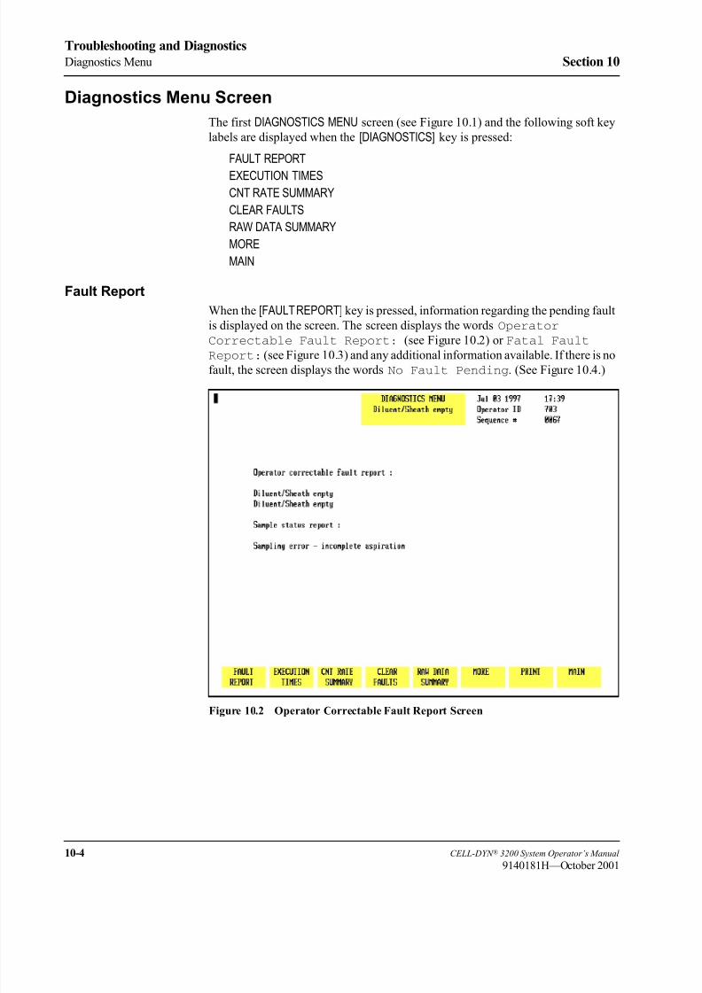
8/21/2019 Equ22-14 CellDyn3200 Op Man
http://slidepdf.com/reader/full/equ22-14-celldyn3200-op-man 446/690
10-4 CELL-DYN ® 3200 System Operator’s Manual
9140181H—October 2001
Troubleshooting and Diagnostics
Diagnostics Menu Section 10
Diagnostics Menu Screen
The first DIAGNOSTICS MENU screen (see Figure 10.1) and the following soft key
labels are displayed when the [DIAGNOSTICS] key is pressed:
FAULT REPORT
EXECUTION TIMESCNT RATE SUMMARY
CLEAR FAULTS
RAW DATA SUMMARY
MORE
MAIN
Fault Report
When the [FAULT REPORT] key is pressed, information regarding the pending fault
is displayed on the screen. The screen displays the words Operator
Correctable Fault Report: (see Figure 10.2) or Fatal Fault
Report: (see Figure 10.3) and any additional information available. If there is no
fault, the screen displays the words No Fault Pending. (See Figure 10.4.)
Figure 10.2 Operator Correctable Fault Report Screen

8/21/2019 Equ22-14 CellDyn3200 Op Man
http://slidepdf.com/reader/full/equ22-14-celldyn3200-op-man 447/690
CELL-DYN ® 3200 System Operator’s Manual 10-5
9140181H—October 2001
Section 10 Troubleshooting and Diagnostics
Figure 10.3 Fatal Fault Report Screen
Figure 10.4 Fault Report — No Fault Pending Screen

8/21/2019 Equ22-14 CellDyn3200 Op Man
http://slidepdf.com/reader/full/equ22-14-celldyn3200-op-man 448/690
10-6 CELL-DYN ® 3200 System Operator’s Manual
9140181H—October 2001
Troubleshooting and Diagnostics
Diagnostics Menu Section 10
Operator correctable faults (for example, waste full, diluent empty) can be cleared
by pressing the [CLEAR FAULT] key after taking corrective action. After corrective
action for a fatal fault, the system must be reinitialized by pressing the
[INITIALIZATION] soft key in the second DIAGNOSTICS MENU screen (refer to
Figure 10.9).
Execution Times
This key is for service use only.
Figure 10.5 Count Rate Summary Screen
CNT Rate Summary
When the [CNT RATE SUMMARY] key is pressed, the following soft key labels (see
Figure 10.5) are displayed:
WOC CNT RATE/WOC CNT GRAPH/WOC CNT DATA *
RBC/PLT CNT RATE/RBC/PLT CNT GRAPH/RBC/PLT CNT DATA *
NOC CNT RATE/NOC CNT GRAPH/NOC CNT DATA *
RETURN
* Key labels alternate between the selections.
NOTE: Once a [CNT RATE] key is pressed, that key toggles between [CNT DATA] and [CNT GRAPH] until the operator exits the screen. The keys then revert
to [CNT RATE].

8/21/2019 Equ22-14 CellDyn3200 Op Man
http://slidepdf.com/reader/full/equ22-14-celldyn3200-op-man 449/690
CELL-DYN ® 3200 System Operator’s Manual 10-7
9140181H—October 2001
Section 10 Troubleshooting and Diagnostics
Figure 10.6 WOC Count Rate Data
Each key displays kinetic data for the selected parameter from the last cycle run.
When each key is pressed, the count rate data is displayed (see Figure 10.6) and the
key label changes to [CNT GRAPH] for that parameter.
Count rate data from the last cycle is displayed in a tabular format. The total count,
time segments and rate per second are displayed for multiple data points from thatcycle. (See Figure 10.6.) When the [CNT GRAPH] key for a particular parameter is
pressed, the rate-per-second data is displayed as a graph. (See Figure 10.7.) The
kinetic data and graph are useful when troubleshooting problems related to these
parameters.
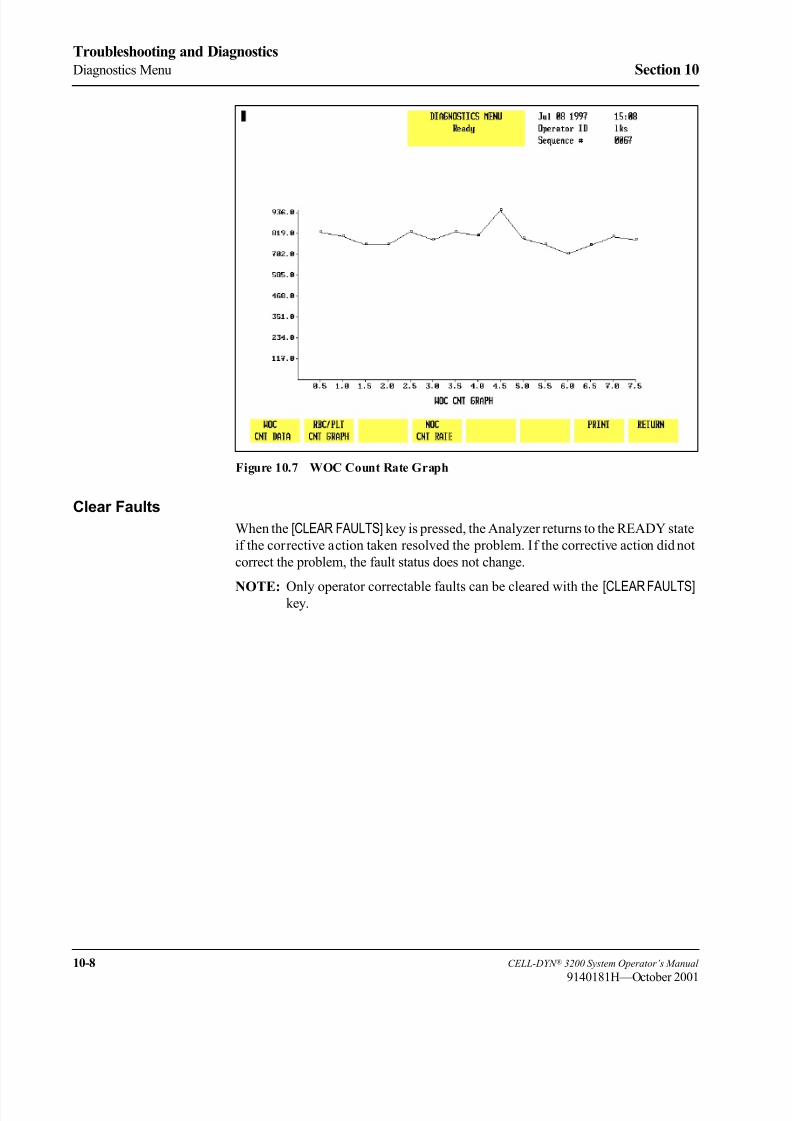
8/21/2019 Equ22-14 CellDyn3200 Op Man
http://slidepdf.com/reader/full/equ22-14-celldyn3200-op-man 450/690
10-8 CELL-DYN ® 3200 System Operator’s Manual
9140181H—October 2001
Troubleshooting and Diagnostics
Diagnostics Menu Section 10
Figure 10.7 WOC Count Rate Graph
Clear Faults
When the [CLEAR FAULTS] key is pressed, the Analyzer returns to the READY state
if the corrective action taken resolved the problem. If the corrective action did not
correct the problem, the fault status does not change.
NOTE: Only operator correctable faults can be cleared with the [CLEAR FAULTS] key.

8/21/2019 Equ22-14 CellDyn3200 Op Man
http://slidepdf.com/reader/full/equ22-14-celldyn3200-op-man 451/690
CELL-DYN ® 3200 System Operator’s Manual 10-9
9140181H—October 2001
Section 10 Troubleshooting and Diagnostics
Figure 10.8 Raw Data Summary Screen
Raw Data Summary
When the [RAW DATA SUMMARY] key is pressed, detailed information pertaining to
the last cycle run is displayed. An example of the RAW DATA SUMMARY screen is
shown in Figure 10.8.
The HGB Reference and Sample readings may be used to assist in troubleshootingerratic or imprecise HGB results.
More
When the [MORE] key is pressed, the second DIAGNOSTICS MENU screen is
displayed. The [MORE] keys on the remaining screens always display the next
DIAGNOSTICS MENU screen.
When the [PRINT] key is pressed, a Diagnostic Report is printed. This report
contains information pertinent to the data displayed on the screen at the time the
key is pressed. If no data is displayed on the screen, the report prints the currentfault status.
The [PRINT] key functions in this way on each screen. Therefore, it will not be
discussed again in this section.

8/21/2019 Equ22-14 CellDyn3200 Op Man
http://slidepdf.com/reader/full/equ22-14-celldyn3200-op-man 452/690
10-10 CELL-DYN ® 3200 System Operator’s Manual
9140181H—October 2001
Troubleshooting and Diagnostics
Diagnostics Menu Section 10
Main
The [MAIN] key is used to return to the MAIN MENU screen. The [MAIN] key appears
on each primary DIAGNOSTICS MENU screen and works the same way on each
screen.
Figure 10.9 Second Diagnostics Menu Screen
Second Diagnostics Menu ScreenWhen the [MORE] key on the first DIAGNOSTICS MENU screen is pressed, the second
DIAGNOSTICS MENU screen (see Figure 10.9) and the following soft key labels are
displayed:
MOTOR OPERATION
SOLENOID OPERATION
PUMP OPERATION
DRAIN ACCUMULATOR
INITIALIZATION
MORE
MAIN
Motor Operation
This key should be used only by an authorized Abbott representative. The system
must be initialized after this key is pressed.

8/21/2019 Equ22-14 CellDyn3200 Op Man
http://slidepdf.com/reader/full/equ22-14-celldyn3200-op-man 453/690
CELL-DYN ® 3200 System Operator’s Manual 10-11
9140181H—October 2001
Section 10 Troubleshooting and Diagnostics
Solenoid Operation
This key should be used only by an authorized Abbott representative. The system
must be initialized after this key is pressed.
Figure 10.10 Pump Operation Screen
Pump Operation
When the [PUMP OPERATION] key is pressed, the following soft key labels (see
Figure 10.10) are displayed:
VACUUM ON/VACUUM OFF (The key label alternates between the selections.)
PRESSURE ON/PRESSURE OFF (The key label alternates between the selections.)
INHIBIT PUMPS/ENABLE PUMPS (Displayed when VACUUM or PRESSURE keys
are pressed.)
VACUUM TEST
PRESSURE TESTDIAGNOSTICS

8/21/2019 Equ22-14 CellDyn3200 Op Man
http://slidepdf.com/reader/full/equ22-14-celldyn3200-op-man 454/690
10-12 CELL-DYN ® 3200 System Operator’s Manual
9140181H—October 2001
Troubleshooting and Diagnostics
Diagnostics Menu Section 10
Figure 10.11 Pump Operation Screen — Vacuum ON
Vacuum On
When the [VACUUM ON] key is pressed, the key label changes to [VACUUM OFF], the
vacuum pump is turned ON and the screen displays the message Vacuum Is On.
(See Figure 10.11.) Press the [VACUUM OFF] key to turn the pump OFF.
NOTE: The pump is automatically turned OFF and control of the pump isreturned to the instrument when the screen is exited.
This key is useful for troubleshooting vacuum problems. If the pump does not turn
ON when the key is pressed, the pump may be the cause of the vacuum problem.
Pressure On
When the [PRESSURE ON] key is pressed, the key label changes to [PRESSUREOFF], the pressure pump is turned ON and the screen displays the message
Pressure Is On. Press the [PRESSURE OFF] key to turn the pump OFF.
NOTE: The pump is automatically turned OFF and control of the pump is
returned to the instrument when the screen is exited.
This key is useful for troubleshooting pressure problems. If the pump does not turn
ON when the key is pressed, the pump may be the cause of the pressure problem.

8/21/2019 Equ22-14 CellDyn3200 Op Man
http://slidepdf.com/reader/full/equ22-14-celldyn3200-op-man 455/690
CELL-DYN ® 3200 System Operator’s Manual 10-13
9140181H—October 2001
Section 10 Troubleshooting and Diagnostics
Figure 10.12 Inhibit Pumps Screen
Inhibit Pumps
When the [VACUUM] or [PRESSURE] key is pressed, the [INHIBIT PUMPS] key
appears. (See Figure 10.12.) When the [INHIBIT PUMPS] key is pressed, the
operation of the pumps is inhibited (no vacuum and pressure are produced), the
screen displays the message Vacuum Is Inhibited, and the key label changes
to [ENABLE PUMPS]. Press the [ENABLE PUMPS] key to enable pump operation.
NOTE: The pumps are automatically enabled and control of them is returned to
the instrument when the screen is exited, even if the pumps were disabled
while in the screen.
This key is useful when performing maintenance or troubleshooting procedures
that require a vacuum or pressure line to be removed.
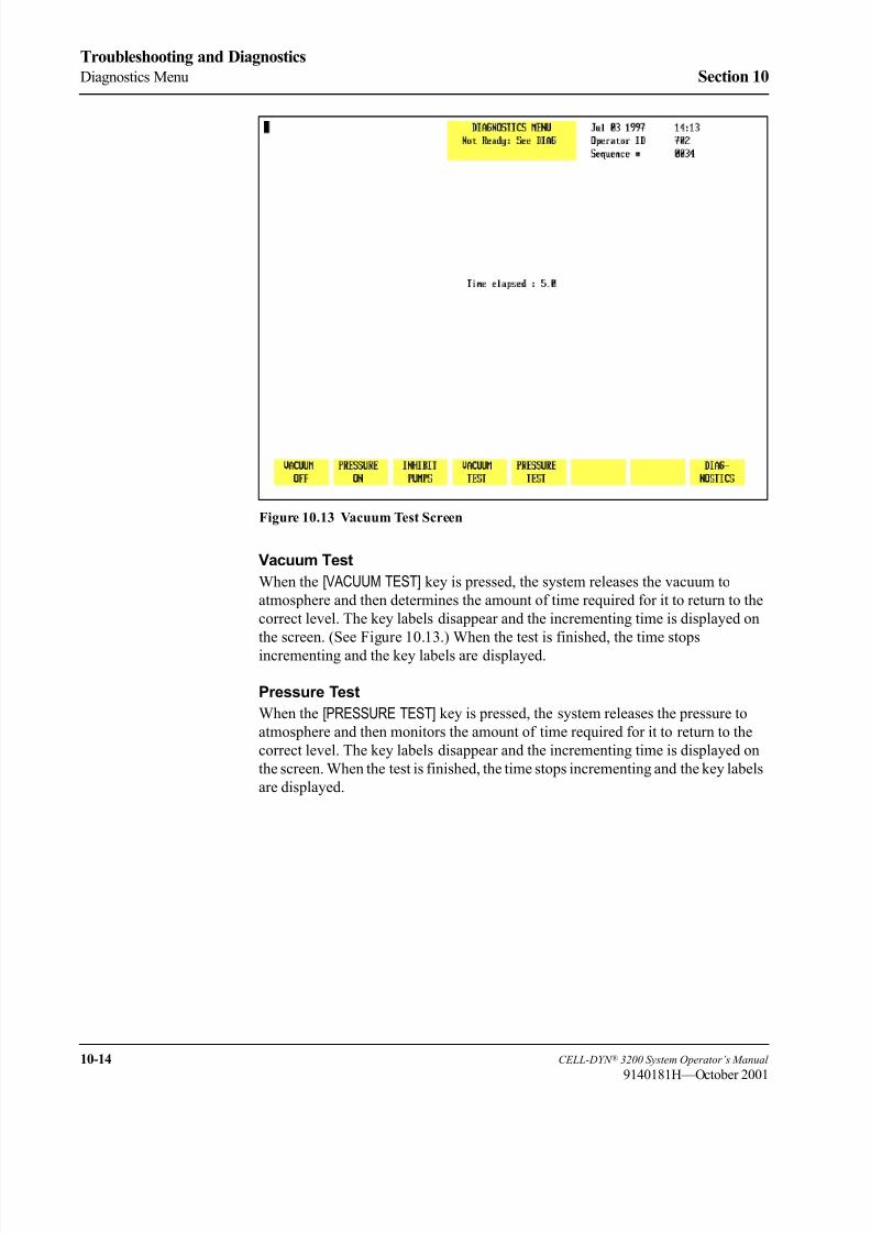
8/21/2019 Equ22-14 CellDyn3200 Op Man
http://slidepdf.com/reader/full/equ22-14-celldyn3200-op-man 456/690
10-14 CELL-DYN ® 3200 System Operator’s Manual
9140181H—October 2001
Troubleshooting and Diagnostics
Diagnostics Menu Section 10
Figure 10.13 Vacuum Test Screen
Vacuum Test
When the [VACUUM TEST] key is pressed, the system releases the vacuum to
atmosphere and then determines the amount of time required for it to return to the
correct level. The key labels disappear and the incrementing time is displayed on
the screen. (See Figure 10.13.) When the test is finished, the time stops
incrementing and the key labels are displayed.
Pressure Test
When the [PRESSURE TEST] key is pressed, the system releases the pressure to
atmosphere and then monitors the amount of time required for it to return to the
correct level. The key labels disappear and the incrementing time is displayed on
the screen. When the test is finished, the time stops incrementing and the key labels
are displayed.

8/21/2019 Equ22-14 CellDyn3200 Op Man
http://slidepdf.com/reader/full/equ22-14-celldyn3200-op-man 457/690
CELL-DYN ® 3200 System Operator’s Manual 10-15
9140181H—October 2001
Section 10 Troubleshooting and Diagnostics
Figure 10.14 Drain Accumulators Screen
Drain Accumulator
When the [DRAIN ACCUMULATOR] key is pressed, the internal vacuum
accumulators are drained of accumulated fluid. This key is used to correct the
“Vacuum Accumulator Wet” fault. The screen displays (see Figure 10.14) the
following message:
After draining the accumulators, press INITIALIZATION
key to return to normal operation.
When the process is completed, the system must be initialized and primed. See
Initialization below.
Initialization
When the [INITIALIZATION] key is pressed, the Analyzer is initialized. This is
necessary when a fatal fault has occurred.
After the Analyzer is initialized, it must be primed. To prime the Analyzer, go to
the MAIN MENU and press the [RUN] soft key.

8/21/2019 Equ22-14 CellDyn3200 Op Man
http://slidepdf.com/reader/full/equ22-14-celldyn3200-op-man 458/690
10-16 CELL-DYN ® 3200 System Operator’s Manual
9140181H—October 2001
Troubleshooting and Diagnostics
Diagnostics Menu Section 10
Figure 10.15 Third Diagnostics Menu Screen
Third Diagnostics Menu Screen
When the [MORE] key in the second DIAGNOSTICS MENU is pressed, the third
DIAGNOSTICS MENU screen (see Figure 10.15) and the following soft key labels
are displayed:
SOFTWARE VERSION *
DIGITAL READINGS *
VOLTAGE READINGS
GAIN ADJUSTMENT *
MORE
MAIN
* These keys are for service use only.

8/21/2019 Equ22-14 CellDyn3200 Op Man
http://slidepdf.com/reader/full/equ22-14-celldyn3200-op-man 459/690
CELL-DYN ® 3200 System Operator’s Manual 10-17
9140181H—October 2001
Section 10 Troubleshooting and Diagnostics
Figure 10.16 Voltage Readings Screen
Voltage Readings
When the [VOLTAGE READINGS] key is pressed, the voltage and vacuum/pressure
value from a test point, measured at the moment when the key was pressed, is
displayed. (See Figure 10.16.) The following additional soft key labels are
displayed:
FINISH SELECT *
SELECT *
* These two keys are for service use only.
The data provided by the VOLTAGE READINGS screen can be useful in determining
if a problem is caused by a hardware malfunction.
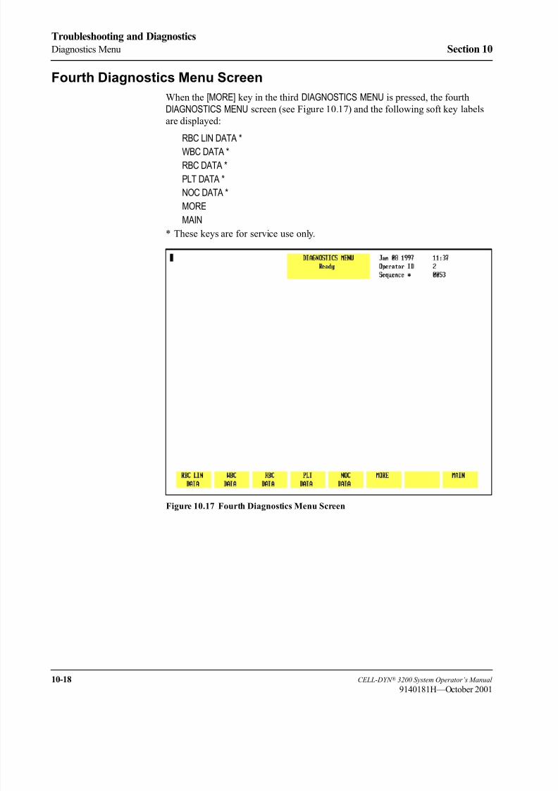
8/21/2019 Equ22-14 CellDyn3200 Op Man
http://slidepdf.com/reader/full/equ22-14-celldyn3200-op-man 460/690
10-18 CELL-DYN ® 3200 System Operator’s Manual
9140181H—October 2001
Troubleshooting and Diagnostics
Diagnostics Menu Section 10
Fourth Diagnostics Menu Screen
When the [MORE] key in the third DIAGNOSTICS MENU is pressed, the fourth
DIAGNOSTICS MENU screen (see Figure 10.17) and the following soft key labels
are displayed:
RBC LIN DATA *WBC DATA *
RBC DATA *
PLT DATA *
NOC DATA *
MORE
MAIN
* These keys are for service use only.
Figure 10.17 Fourth Diagnostics Menu Screen

8/21/2019 Equ22-14 CellDyn3200 Op Man
http://slidepdf.com/reader/full/equ22-14-celldyn3200-op-man 461/690
CELL-DYN ® 3200 System Operator’s Manual 10-19
9140181H—October 2001
Section 10 Troubleshooting and Diagnostics
Fifth Diagnostics Menu Screen — CS Model
For CS models, when the [MORE] key in the fourth DIAGNOSTICS MENU is pressed,
the fifth and last DIAGNOSTICS MENU screen (see Figure 10.18) and the following
soft key labels are displayed:
SERIAL TESTBAR CODE ALIGNMENT *
FPU TEST*
TOWER TEST *
DOOR TEST *
MORE
MAIN
* These keys are for service use only.
Figure 10.18 Fifth Diagnostics Menu Screen (CELL-DYN 3200CS)

8/21/2019 Equ22-14 CellDyn3200 Op Man
http://slidepdf.com/reader/full/equ22-14-celldyn3200-op-man 462/690
10-20 CELL-DYN ® 3200 System Operator’s Manual
9140181H—October 2001
Troubleshooting and Diagnostics
Diagnostics Menu Section 10
Serial Test
The [SERIAL TEST] key is used to test the functionality of the COM1 port (referred
to as the “serial interface connector”) at the rear of the instrument. This test is
designed to assist in troubleshooting problems with interfacing to a Laboratory
Information System (LIS). The loop-back connector must be connected to the
COM1 port before performing the test.
NOTE: If the laboratory does not have a LIS, the loop-back connector may remain
connected to the COM1 port for convenience, as it does not interfere with
routine operation. If a LIS is usually connected, the loop-back connector
should be stored near the instrument when the connector is not in use.
Figure 10.19 Serial Test Screen
When the [SERIAL TEST] key is pressed, the following soft key labels (see
Figure 10.19) are displayed:
STOP TRANSMISS
TRANSMIT MESSAGE
RETURN
The screen displays the following:
Serial Interface Test
1. See Interface Specification.
2. If transmission in progress, press [STOP TRANSMISS]
key first.
3. Attach Loop-back Connector to the serial interface
connector on back of the Data Station.
4. Press the [TRANSMIT MESSAGE] key to start the test.
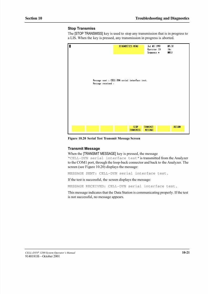
8/21/2019 Equ22-14 CellDyn3200 Op Man
http://slidepdf.com/reader/full/equ22-14-celldyn3200-op-man 463/690
CELL-DYN ® 3200 System Operator’s Manual 10-21
9140181H—October 2001
Section 10 Troubleshooting and Diagnostics
Stop Transmiss
The [STOP TRANSMISS] key is used to stop any transmission that is in progress to
a LIS. When the key is pressed, any transmission in progress is aborted.
Figure 10.20 Serial Test Transmit Message Screen
Transmit Message
When the [TRANSMIT MESSAGE] key is pressed, the message“CELL-DYN serial interface test” is transmitted from the Analyzer
to the COM1 port, through the loop-back connector and back to the Analyzer. The
screen (see Figure 10.20) displays the message:
MESSAGE SENT: CELL-DYN serial interface test.
If the test is successful, the screen displays the message:
MESSAGE RECEIVED: CELL-DYN serial interface test.
This message indicates that the Data Station is communicating properly. If the test
is not successful, no message appears.

8/21/2019 Equ22-14 CellDyn3200 Op Man
http://slidepdf.com/reader/full/equ22-14-celldyn3200-op-man 464/690
10-22 CELL-DYN ® 3200 System Operator’s Manual
9140181H—October 2001
Troubleshooting and Diagnostics
Diagnostics Menu Section 10
Fifth Diagnostics Menu Screen — SL Model
For SL models, when the [MORE] key in the fourth DIAGNOSTICS MENU is pressed,
the fifth and last DIAGNOSTICS MENU screen (see Figure 10.21) and the following
soft key labels are displayed:
SERIAL TESTBAR CODE ALIGNMENT *
FPU TEST *
TOWER TEST *
LOADER TEST *
MORE
MAIN
* These keys are for service use only.
Figure 10.21 Fifth Diagnostics Menu Screen (CELL-DYN 3200SL)
The [SERIAL TEST] and [MORE] keys function in a similar manner to that described
in section Fifth Diagnostics Menu Screen — CS Model .

8/21/2019 Equ22-14 CellDyn3200 Op Man
http://slidepdf.com/reader/full/equ22-14-celldyn3200-op-man 465/690
CELL-DYN ® 3200 System Operator’s Manual 10-23
9140181H—October 2001
Section 10 Troubleshooting and Diagnostics
Troubleshooting Guide
Introduction to TroubleshootingGood troubleshooting skills are learned by using a logical, step-by-step approach
to problem solving. The first step in the process is understanding normal
instrument operation and preventative maintenance. A good working knowledge of
the instrument is essential for identifying and resolving operational problems.
Logical troubleshooting may be divided into three steps:
1. Problem Identification
2. Problem Isolation
3. Corrective Action
Step 1, the problem identification step, is not only identifying what is wrong but
also noting what is right. The investigation should identify the problem area and
eliminate areas that are working correctly. Once this is done, the troubleshooting
process moves quickly to the next step.
Step 2, Problem Isolation, further classifies the problem. Instrument problems are
generally divided into three categories:
Hardware — component related
Software — computer program related
Measurement — related to sample analysis
Typically, hardware and software problems are corrected by an authorized service
representative. Measurement problems are generally operator correctable. Thiscategory is further subdivided into problems related to Sample Handling,
Maintenance or Calibration.
Step 3, Corrective Action, involves taking appropriate action to correct the
problem. If the operator can correct the problem, with or without technical
assistance, normal operation can quickly resume.
This Troubleshooting Guide is designed to enhance the troubleshooting process by
providing information to assist in problem identification, isolation and corrective
action.
NOTE: Generally, conditions that are instrument- or reagent-related will occur on
all samples, including controls. Therefore, it is important to confirminstrument performance by rerunning controls and/or additional patient
specimens.

8/21/2019 Equ22-14 CellDyn3200 Op Man
http://slidepdf.com/reader/full/equ22-14-celldyn3200-op-man 466/690
10-24 CELL-DYN ® 3200 System Operator’s Manual
9140181M—June 2004
Troubleshooting and Diagnostics
Troubleshooting Guide Section 10
Obtaining Technical Assistance
Technical Assistance is obtained by calling Abbott Customer Service. It is
important to provide a clear and detailed description of the problem. When
assistance is needed, please be prepared to provide the following information to
Abbott Customer Service:
1. Instrument Model Name
2. Serial number of the Analyzer
3. Description of the problem
4. The lot numbers and expiration dates of the CELL-DYN reagents and
controls currently in use
5. Examples of sufficient data to facilitate the discussion
Customer Service
United States: 1 (877) 4ABBOTT or 1 (877) 422-2688
Abbott Diagnostics Division
Customer Service
200 Abbott Park Road
Abbott Park, IL 60064, USA
Canada: 1(800) 387-8378
For customers outside the U.S., call your local Customer Service representative.
8/21/2019 Equ22-14 CellDyn3200 Op Man
http://slidepdf.com/reader/full/equ22-14-celldyn3200-op-man 467/690
CELL-DYN ® 3200 System Operator’s Manual 10-25
9140181L—July 2003
Section 10 Troubleshooting and Diagnostics
Troubleshooting Procedures
The procedures in this section are for troubleshooting purposes only. A specific procedure should be performed under one of the following conditions:
1. To correct a problem described in this section
2. At the request of an Abbott Customer Service Specialist.
WARNING: Potential Biohazard. Follow established biosafety practices
when performing maintenance, service or troubleshooting procedures.
Refer to Section 8: Hazards for additional information.
Troubleshooting Tips and Techniques
IntroductionEffective troubleshooting is possible only when the problem is clearly recognized
and the probable cause is isolated. This is always facilitated by obtaining sufficient
information and data pertaining to the specific problem. Carefully observe the
situation. Document the steps that have been taken and record all results.
The following section is designed to guide the operator through a logical series of
steps to obtain information regarding the nature of the problem. If it is necessary to
call for technical assistance, this information should be made available to the
Customer Service Specialist.
Troubleshooting the Background Count
NOTE: For the appropriate corrective action for unacceptable background counts,refer to Table 10.4.
1. Determine which parameter(s) exceed the background count specifications:
WBC, RBC, PLT, HGB, NOC.*
* Background counts for NOC are available in the Data Log.
2. Check the Data Log to determine when the problem first occurred.
3. Check the Reagent Log, Maintenance Log and if applicable, service reports to
see if the problem occurred immediately after a specific action. For example,
did the problem occur immediately after the reagent was changed?
4. Check the Background count in the open and closed modes to see if the
problem is common to both modes. To do this in closed mode, you must havea sample tube filled with diluent/sheath to aspirate for a background count.
5. Note the lot number of the reagent. Is it a new lot?

8/21/2019 Equ22-14 CellDyn3200 Op Man
http://slidepdf.com/reader/full/equ22-14-celldyn3200-op-man 468/690
10-26 CELL-DYN ® 3200 System Operator’s Manual
9140181H—October 2001
Troubleshooting and Diagnostics
Troubleshooting Procedures Section 10
6. Configure the RUN screen to display the appropriate graphic for the
parameter(s) for which the background exceeds the specifications:
Parameter Appropriate Graphic
WBC WBC histogram/scatterplots
RBC RBC and PLT histograms/scatterplots
PLT RBC and PLT histograms/scatterplots
HGB WBC, RBC and PLT histograms
NOC NOC histogram
Obtain several printouts of this information by running multiple background
cycles.
NOTE: Instructions for customizing the RUN screen display are given in
Section 5: Operating Instructions; Subsection: Set Up Instructions,
Customize Report, Customize Displayed Report .
7. Configure the Data Log to display values for WBC, RBC, PLT, HGB, and
NOC. Obtain printouts of the Data Log, including the sequence numbers of
the background cycles.
NOTE: Instructions for customizing the display and printout of the Data
Log are given in Section 5: Operating Instructions; Subsection:
Using the Data Log, Data Log Set Up Procedures.
Troubleshooting Reagent Problems
If a reagent (or reagents) is suspected as the cause of a particular problem, replace
the container. However, the Analyzer has reservoirs that contain a small amount of
reagent to maintain the supply within the system. This supply must be depleted
before installing the new reagent.
NOTE: There is no reservoir for either the HGB Lyse reagent or WBC lyse
reagent. The amount of lyse contained in the lyse supply tubing is
sufficient to maintain the system’s supply. The lyse tubing is drained and
filled by pressing the appropriate reagent key displayed on the REAGENTRESERVOIR screen described below.
To ensure that the new reagent is actually in the system, proceed as follows:
1. From the first SPECIAL PROTOCOLS screen, press [REAGENT RESERVOIR].
2. From the REAGENT RESERVOIR screen, press the soft key for the desired
reagent and follow the instructions given on the screen.
3. Wipe the reagent line with a lint-free pad before placing it in the newcontainer. Place the line in the container and secure the cap.
4. Press the appropriate soft key to refill the reservoir.
5. Run five Background counts before assessing the results.
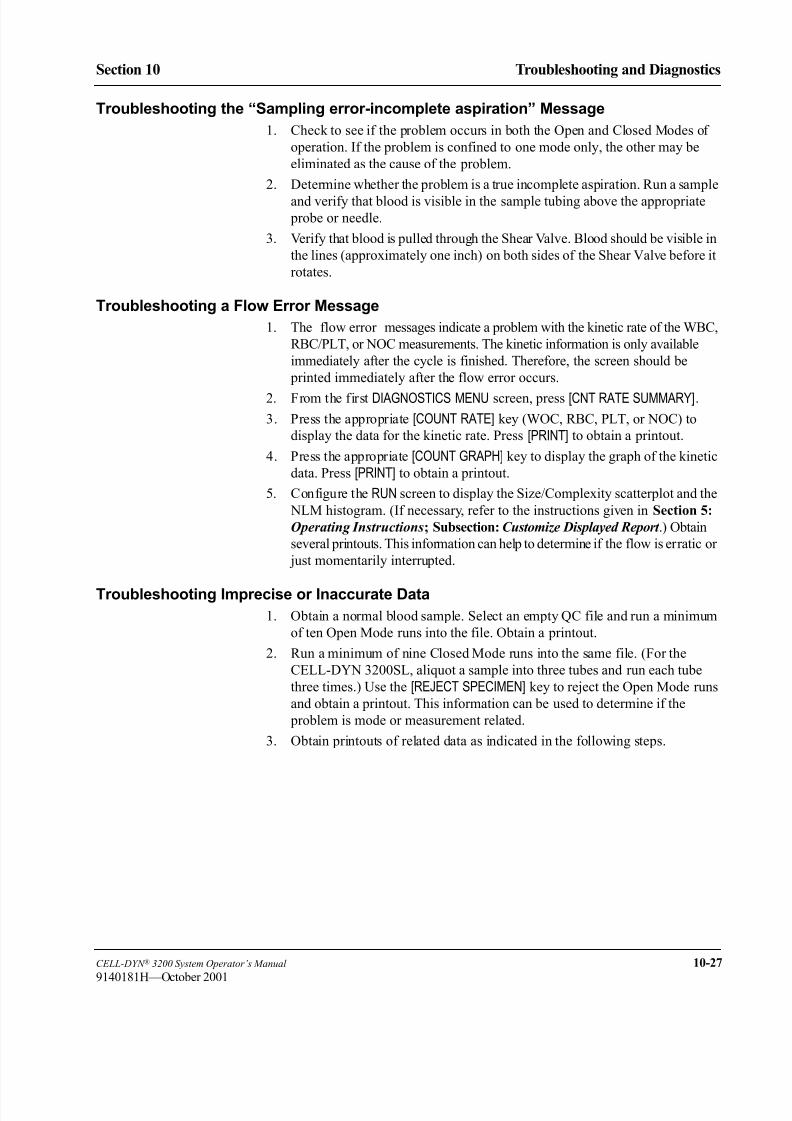
8/21/2019 Equ22-14 CellDyn3200 Op Man
http://slidepdf.com/reader/full/equ22-14-celldyn3200-op-man 469/690
CELL-DYN ® 3200 System Operator’s Manual 10-27
9140181H—October 2001
Section 10 Troubleshooting and Diagnostics
Troubleshooting the “Sampling error-incomplete aspiration” Message
1. Check to see if the problem occurs in both the Open and Closed Modes of
operation. If the problem is confined to one mode only, the other may be
eliminated as the cause of the problem.
2. Determine whether the problem is a true incomplete aspiration. Run a sample
and verify that blood is visible in the sample tubing above the appropriate
probe or needle.
3. Verify that blood is pulled through the Shear Valve. Blood should be visible in
the lines (approximately one inch) on both sides of the Shear Valve before it
rotates.
Troubleshooting a Flow Error Message
1. The flow error messages indicate a problem with the kinetic rate of the WBC,
RBC/PLT, or NOC measurements. The kinetic information is only available
immediately after the cycle is finished. Therefore, the screen should be
printed immediately after the flow error occurs.
2. From the first DIAGNOSTICS MENU screen, press [CNT RATE SUMMARY].
3. Press the appropriate [COUNT RATE] key (WOC, RBC, PLT, or NOC) to
display the data for the kinetic rate. Press [PRINT] to obtain a printout.
4. Press the appropriate [COUNT GRAPH] key to display the graph of the kinetic
data. Press [PRINT] to obtain a printout.
5. Configure the RUN screen to display the Size/Complexity scatterplot and the
NLM histogram. (If necessary, refer to the instructions given in Section 5:
Operating Instructions; Subsection: Customize Displayed Report .) Obtain
several printouts. This information can help to determine if the flow is erratic or
just momentarily interrupted.
Troubleshooting Imprecise or Inaccurate Data
1. Obtain a normal blood sample. Select an empty QC file and run a minimum
of ten Open Mode runs into the file. Obtain a printout.
2. Run a minimum of nine Closed Mode runs into the same file. (For the
CELL-DYN 3200SL, aliquot a sample into three tubes and run each tube
three times.) Use the [REJECT SPECIMEN] key to reject the Open Mode runs
and obtain a printout. This information can be used to determine if the
problem is mode or measurement related.
3. Obtain printouts of related data as indicated in the following steps.

8/21/2019 Equ22-14 CellDyn3200 Op Man
http://slidepdf.com/reader/full/equ22-14-celldyn3200-op-man 470/690
10-28 CELL-DYN ® 3200 System Operator’s Manual
9140181L—July 2003
Troubleshooting and Diagnostics
Troubleshooting Procedures Section 10
4. WBC:
• Configure the RUN screen to display the following and obtain printouts by
pressing the Print screen key on the keyboard. (This requires two printouts
per sample.)
Printout 1:
Size-Cmp (0—10)
Grn-Lob (90D—90)
WBC 0—90 deg
RBC 90—10 deg
• Printout 2:
N-L-M histogram
M-P histogram
NOC histogram
If necessary, refer to the directions given in Section 5: Operating
Instructions for customizing the display.
• Obtain printouts of the kinetic data for WBC for several samples. Fromthe first DIAGNOSTICS MENU screen, press [CNT RATE SUMMARY]. Press
[WOC CNT RATE] to display the data for the kinetic rate followed by
[PRINT] to obtain a printout. Press [WOC CNT GRAPH] to display the graph
of the kinetic data followed by [PRINT] to obtain a printout.
• If there is a flagging problem or a problem with an abnormal sample,
obtain a printout of a normal sample for comparison.
• Obtain a printout of the RAW DATA SUMMARY screen immediately after
the problem sample is run. From the first DIAGNOSTICS MENU screen,
press [RAW DATA SUMMARY] followed by [PRINT] to obtain a printout.
• Configure the Data Log to display and print WBC values. (If necessary,refer to the instructions given in Section 5: Operating Instructions.) Print
the results for the last 100 cycles.
5. RBC, HGB, MCV and PLT:
• Configure the RUN screen to display the RBC and PLT
histograms/scatterplots. Obtain printouts of problem samples.
• Obtain a printout of the RAW DATA SUMMARY screen immediately after
the problem sample is run. From the first DIAGNOSTICS MENU screen,
press [RAW DATA SUMMARY] followed by [PRINT] to obtain a printout.
• Obtain a printout of the X-B data. In the MAIN MENU, press [QUALITY
CONTROL] followed by [X-B FILE]. If necessary, press [X-B RBC DATA] todisplay the X-B RBC data and press [PRINT] to obtain a printout.
• Check the Hemoglobin Reference and verify that its values are within
2050 ± 250.
• Check the hemoglobin Flow Cell if the reference value is <1800.
• If the Hemoglobin Reference Value is >2300, call Abbott Customer
Service.
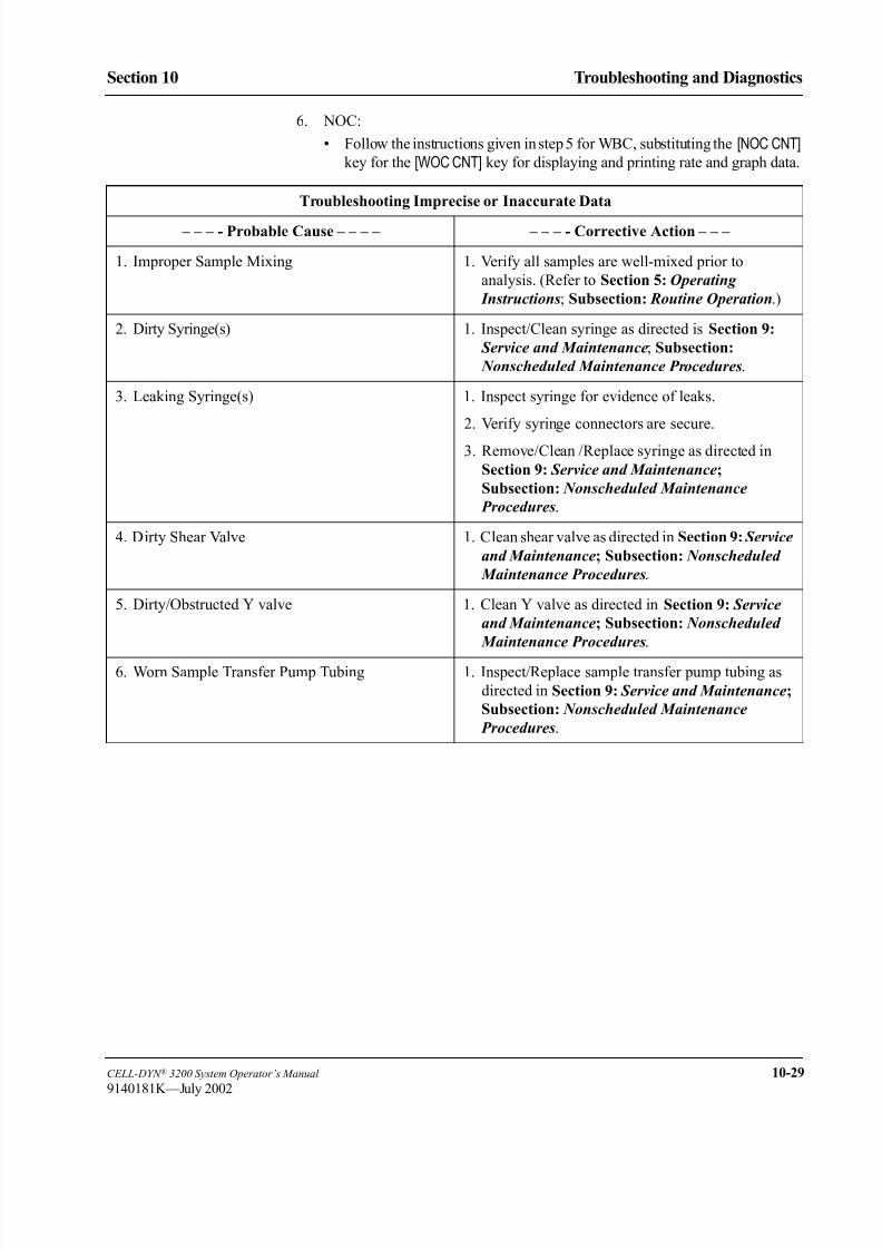
8/21/2019 Equ22-14 CellDyn3200 Op Man
http://slidepdf.com/reader/full/equ22-14-celldyn3200-op-man 471/690
CELL-DYN ® 3200 System Operator’s Manual 10-29
9140181K—July 2002
Section 10 Troubleshooting and Diagnostics
6. NOC:
• Follow the instructions given in step 5 for WBC, substituting the [NOC CNT] key for the [WOC CNT] key for displaying and printing rate and graph data.
Troubleshooting Imprecise or Inaccurate Data
– – – - Probable Cause – – – – – – – - Corrective Action – – –
1. Improper Sample Mixing 1. Verify all samples are well-mixed prior to
analysis. (Refer to Section 5: Operating
Instructions; Subsection: Routine Operation.)
2. Dirty Syringe(s) 1. Inspect/Clean syringe as directed is Section 9:
Service and Maintenance; Subsection:
Nonscheduled Maintenance Procedures.
3. Leaking Syringe(s) 1. Inspect syringe for evidence of leaks.
2. Verify syringe connectors are secure.
3. Remove/Clean /Replace syringe as directed in
Section 9: Service and Maintenance;
Subsection: Nonscheduled Maintenance
Procedures.
4. Dirty Shear Valve 1. Clean shear valve as directed in Section 9: Service
and Maintenance; Subsection: Nonscheduled
Maintenance Procedures.
5. Dirty/Obstructed Y valve 1. Clean Y valve as directed in Section 9: Service
and Maintenance; Subsection: Nonscheduled
Maintenance Procedures.
6. Worn Sample Transfer Pump Tubing 1. Inspect/Replace sample transfer pump tubing as
directed in Section 9: Service and Maintenance;
Subsection: Nonscheduled Maintenance
Procedures.

8/21/2019 Equ22-14 CellDyn3200 Op Man
http://slidepdf.com/reader/full/equ22-14-celldyn3200-op-man 472/690
10-30 CELL-DYN ® 3200 System Operator’s Manual
9140181H—October 2001
Troubleshooting and Diagnostics
Troubleshooting Procedures Section 10
NOTES

8/21/2019 Equ22-14 CellDyn3200 Op Man
http://slidepdf.com/reader/full/equ22-14-celldyn3200-op-man 473/690
CELL-DYN ® 3200 System Operator’s Manual 10-31
9140181H—October 2001
Section 10 Troubleshooting and Diagnostics
Instrument Conditions and Messages
OverviewInstrument conditions can be divided into two categories, those that generate
messages, and those that do not. The messages will be displayed in the Status Box
and/or the Bulletin Line.
NOTE: For information on Suspect Parameter Flags, refer to Section 3:
Principles of Operation; Subsection: Operational Messages and Data
Flagging .
Instrument messages fall into two categories:
1. Status Messages — inform the operator of the instrument’s status or
prompt the operator to take action relative to the last
operator entry
2. Fault Messages — indicate fault or error detection
The status conditions are listed in Table 10.1. This table defines each message and
indicates its display location.
The fault conditions and messages are listed as follows:
• General fault conditions are listed in Table 10.2.
• Sample-Related fault conditions are listed in Table 10.3.
• Non-functional fault conditions are listed in Table 10.4.
Each of the tables is designed with the Message or Condition, display location (if
applicable), and additional information centered on the first line. The
corresponding Explanation/Action or Probable Cause/Corrective Action is
indicated immediately below each Message or Problem.

8/21/2019 Equ22-14 CellDyn3200 Op Man
http://slidepdf.com/reader/full/equ22-14-celldyn3200-op-man 474/690
10-32 CELL-DYN ® 3200 System Operator’s Manual
9140181H—October 2001
Troubleshooting and Diagnostics
Instrument Conditions and Messages Section 10
NOTES

8/21/2019 Equ22-14 CellDyn3200 Op Man
http://slidepdf.com/reader/full/equ22-14-celldyn3200-op-man 475/690
CELL-DYN ® 3200 System Operator’s Manual 10-33
9140181L—July 2003
Section 10 Troubleshooting and Diagnostics
Tables for Instrument Conditions and Messages
Index of Table 10.1: Status ConditionsCondition Page
Ready/SB . . . . . . . . . . . . . . . . . . . . . . . . . . . . . . . . . . . . . . . . . . . . . . . . . . . . . . . . . . . . . . . . . . . . . . . . . . . 10-34
Selecting open/closed mode/SB . . . . . . . . . . . . . . . . . . . . . . . . . . . . . . . . . . . . . . . . . . . . . . . . . . . . . . . . . . 10-34
Entering standby/SB . . . . . . . . . . . . . . . . . . . . . . . . . . . . . . . . . . . . . . . . . . . . . . . . . . . . . . . . . . . . . . . . . . . 10-34
Standby/SB . . . . . . . . . . . . . . . . . . . . . . . . . . . . . . . . . . . . . . . . . . . . . . . . . . . . . . . . . . . . . . . . . . . . . . . . . . 10-34
Initialized/SB . . . . . . . . . . . . . . . . . . . . . . . . . . . . . . . . . . . . . . . . . . . . . . . . . . . . . . . . . . . . . . . . . . . . . . . . 10-34
Unpinching valves/SB . . . . . . . . . . . . . . . . . . . . . . . . . . . . . . . . . . . . . . . . . . . . . . . . . . . . . . . . . . . . . . . . . 10-34
Clearing fault/SB . . . . . . . . . . . . . . . . . . . . . . . . . . . . . . . . . . . . . . . . . . . . . . . . . . . . . . . . . . . . . . . . . . . . . 10-35
Limits were changed to correct out-of-range values/BL . . . . . . . . . . . . . . . . . . . . . . . . . . . . . . . . . . . . . . . 10-35
Entries making upper limit = lower limit were rejected/BL. . . . . . . . . . . . . . . . . . . . . . . . . . . . . . . . . . . . . 10-35Limits were exchanged to make upper > lower/BL . . . . . . . . . . . . . . . . . . . . . . . . . . . . . . . . . . . . . . . . . . . 10-35
Westgard Warning — See Levey Jennings/BL. . . . . . . . . . . . . . . . . . . . . . . . . . . . . . . . . . . . . . . . . . . . . . . 10-35
No Entry Found/BL . . . . . . . . . . . . . . . . . . . . . . . . . . . . . . . . . . . . . . . . . . . . . . . . . . . . . . . . . . . . . . . . . . . 10-36
Duplicated Specimen ID on the new line/BL. . . . . . . . . . . . . . . . . . . . . . . . . . . . . . . . . . . . . . . . . . . . . . . . 10-36
Sample Loader is busy/BL . . . . . . . . . . . . . . . . . . . . . . . . . . . . . . . . . . . . . . . . . . . . . . . . . . . . . . . . . . . . . . 10-36
Change Sampler in Ready State Only/BL . . . . . . . . . . . . . . . . . . . . . . . . . . . . . . . . . . . . . . . . . . . . . . . . . . 10-36
Change Sampler when Sample Loader is not busy/BL . . . . . . . . . . . . . . . . . . . . . . . . . . . . . . . . . . . . . . . . 10-36
Loader Status 143: samples completed/BL . . . . . . . . . . . . . . . . . . . . . . . . . . . . . . . . . . . . . . . . . . . . . . . . . 10-36
Loader Warning 145: unload area full/BL . . . . . . . . . . . . . . . . . . . . . . . . . . . . . . . . . . . . . . . . . . . . . . . . . . 10-37
Loader Warning 146: unload area nearly full/BL. . . . . . . . . . . . . . . . . . . . . . . . . . . . . . . . . . . . . . . . . . . . . 10-37Loader Warning 157: mix dropped tubes corrected by delay/BL. . . . . . . . . . . . . . . . . . . . . . . . . . . . . . . . . 10-37
Loader Status 158: load zone empty/BL. . . . . . . . . . . . . . . . . . . . . . . . . . . . . . . . . . . . . . . . . . . . . . . . . . . . 10-37

8/21/2019 Equ22-14 CellDyn3200 Op Man
http://slidepdf.com/reader/full/equ22-14-celldyn3200-op-man 476/690
10-34 CELL-DYN ® 3200 System Operator’s Manual
9140181H—October 2001
Troubleshooting and Diagnostics
Tables for Instrument Conditions and Messages Section 10
Table 10.1 Status Conditions
Each message is followed by one of the abbreviations shown below indicating
where that message appears on the screen:
BL — Bulletin Line
SB — Status Box
Ready/SB
– – – – – – – – – – – – – – – – – Explanation/Action – – – – – – – – – – – – – – –
The Analyzer is ready to process samples.
Selecting open/closed mode/SB
– – – – – – – – – – – – – – – – – Explanation/Action – – – – – – – – – – – – – – –
The [CHANGE SAMPLER] key was pressed and the Analyzer is changing to the
selected mode of operation.
Resume processing when the READY message is displayed in the Status Box.
Entering standby/SB
– – – – – – – – – – – – – – – – – Explanation/Action – – – – – – – – – – – – – –
The instrument has been idle for four hours and therefore is automatically
performing a cleaning cycle before entering the STANDBY state. (Pressing the [DAILY SHUTDOWN] key also initiates this message.)
When the cycle is finished, press [RUN] to prime the system and bring the
instrument to the READY state. Resume operation when the cycle is finished.
Standby/SB
– – – – – – – – – – – – – – – – – Explanation/Action – – – – – – – – – – – – – –
The instrument has entered the STANDBY state.
Press [RUN] or [PRIME] to prime the system and bring the instrument to the
READY state. Resume operation when the cycle is finished.
Initialized/SB
The Analyzer hardware initialization is completed.
Press [RUN] to prime the system and bring the instrument to the READY state.
Resume operation when the cycle is finished.
Unpinching valves/SB
– – – – – – – – – – – – – – – – – Explanation/Action – – – – – – – – – – – – – –
The Analyzer was in standby for a predetermined time period and therefore the
valves are being exercised to be sure that tubing is not pinched shut.
Analyzer status will change back to STANDBY when the unpinching operation
is completed.

8/21/2019 Equ22-14 CellDyn3200 Op Man
http://slidepdf.com/reader/full/equ22-14-celldyn3200-op-man 477/690
CELL-DYN ® 3200 System Operator’s Manual 10-35
9140181H—October 2001
Section 10 Troubleshooting and Diagnostics
Clearing fault/SB
– – – – – – – – – – – – – – – – – Explanation/Action – – – – – – – – – – – – – –
The [CLEAR FAULT] key was pressed after an operator-correctable fault was
detected.
Resume operation when READY is displayed in the Status Box and the READY
indicator light on the status indicator panel is illuminated in green.
Limits were changed to correct out-of-range values/BL
– – – – – – – – – – – – – – – – – Explanation/Action – – – – – – – – – – – – – –
A mathematically incorrect limit was manually entered (using [MEANS/LIMITS])during setup of a QC file. The numbers entered generated a range containing a
number greater than the largest number allowed or less than zero. Therefore, the
limits were automatically changed.
Check to be sure the entered values are correct. If appropriate, recalculate themean and limits and enter correct values.
Entries making upper limit = lower limit were rejected/BL
– – – – – – – – – – – – – – – – – Explanation/Action – – – – – – – – – – – – – –
A mathematically incorrect limit was entered (using [RANGE ENTRY]) during
setup of a QC file. The currently entered numbers are not accepted and the
previously entered numbers for the parameter(s) remain.
Check to be sure the entered values are correct.
Limits were exchanged to make upper > lower/BL
– – – – – – – – – – – – – – – – – Explanation/Action – – – – – – – – – – – – – –
A mathematically incorrect limit was entered (using [RANGE ENTRY]) during
setup of a QC file. The numbers entered caused the upper limit to be less than the
lower limit. Therefore, the numbers were automatically exchanged.
Check to be sure the entered values are correct. If appropriate, enter correct
values.
Westgard Warning — See Levey Jennings/BL
The message is displayed on the VIEW QC LOG screen only.
– – – – – – – – – – – – – – – – – Explanation/Action – – – – – – – – – – – – – –
The Westgard® Rules were selected during set up of the QC file and the data in
the file has violated one or more of the selected rules.
Review the data in the QC file and take appropriate action.
Table 10.1 Status Conditions (Continued)

8/21/2019 Equ22-14 CellDyn3200 Op Man
http://slidepdf.com/reader/full/equ22-14-celldyn3200-op-man 478/690
10-36 CELL-DYN ® 3200 System Operator’s Manual
9140181H—October 2001
Troubleshooting and Diagnostics
Tables for Instrument Conditions and Messages Section 10
No Entry Found/BL
– – – – – – – – – – – – – – – – – Explanation/Action – – – – – – – – – – – – – –
The number (sequence number or specimen ID number) entered on the DATA
LOG SEARCH screen is not present in the data log.
Check that the entry was correct. If appropriate, enter the correct number.
Duplicated Specimen ID on the new line/BL
– – – – – – – – – – – – – – – – – Explanation/Action – – – – – – – – – – – – – –
The Work List already contains a bar code number that has been entered.
It is not possible to enter the same bar code number twice in the Work List. If
appropriate, delete the previous entry and re-enter the number.
Sample Loader is busy/BL
– – – – – – – – – – – – – – – – – Explanation/Action – – – – – – – – – – – – – –
An action was requested during Sample Loader operation and the Sample Loader
cannot perform it.
Press the [STOP LOADER] soft key before requesting the desired action.
Change Sampler in Ready State Only/BL
– – – – – – – – – – – – – – – – – Explanation/Action – – – – – – – – – – – – – –
The [CHANGE SAMPLER] key was pressed while the Analyzer was busy.
The [CHANGE SAMPLER] key can only be pressed when the Analyzer is in the
READY state.
Change Sampler when Sample Loader is not busy/BL
– – – – – – – – – – – – – – – – – Explanation/Action – – – – – – – – – – – – – –
The [CHANGE SAMPLER] key was pressed while the Sampler Loader was busy.
Press the [STOP LOADER] soft key before pressing [CHANGE SAMPLER].
Loader Status 143: samples completed/BL
– – – – – – – – – – – – – – – – – Explanation/Action – – – – – – – – – – – – – –
The last rack in the load zone has been processed. NOTE: The Sample Loader
halts.
No corrective action is necessary. When you wish to run additional samples in
the Sample Loader, load racks and press the [START LOADER] key.
Table 10.1 Status Conditions (Continued)

8/21/2019 Equ22-14 CellDyn3200 Op Man
http://slidepdf.com/reader/full/equ22-14-celldyn3200-op-man 479/690
CELL-DYN ® 3200 System Operator’s Manual 10-37
9140181L—July 2003
Section 10 Troubleshooting and Diagnostics
Loader Warning 145: unload area full/BL
– – – – – – – – – – – – – – – – – Explanation/Action – – – – – – – – – – – – – –
The unload area contains 5 racks. NOTE: The Sample Loader halts.
No corrective action is necessary. When you wish to run additional samples in
the Sample Loader, remove the racks from the unload area and press the [STARTLOADER] key.
Loader Warning 146: unload area nearly full/BL
– – – – – – – – – – – – – – – – – Explanation/Action – – – – – – – – – – – – – –
The unload area contains 4 racks.
No corrective action is necessary. If a rack is being processed and there are no
other faults, the Sample Loader will continue to operate.
Loader Warning 157: mix dropped tubes corrected by delay/BL
– – – – – – – – – – – – – – – – – Explanation/Action – – – – – – – – – – – – – –
Tube was sensed as missing from tube position 3 or 4 at the end of the mixing
cycle, however it was sensed correctly after additional short wait period.
No corrective action is necessary if there are no Loader Faults displayed.
Loader Status 158: load zone empty/BL
– – – – – – – – – – – – – – – – – Explanation/Action – – – – – – – – – – – – – –
The load zone empty sensor is not sensing the presence of a rack in the load zone.
NOTE: The Sample Loader halts.
When you wish to run samples in the Sample Loader, load tubes in racks and press the [START LOADER] key.
Table 10.1 Status Conditions (Continued)
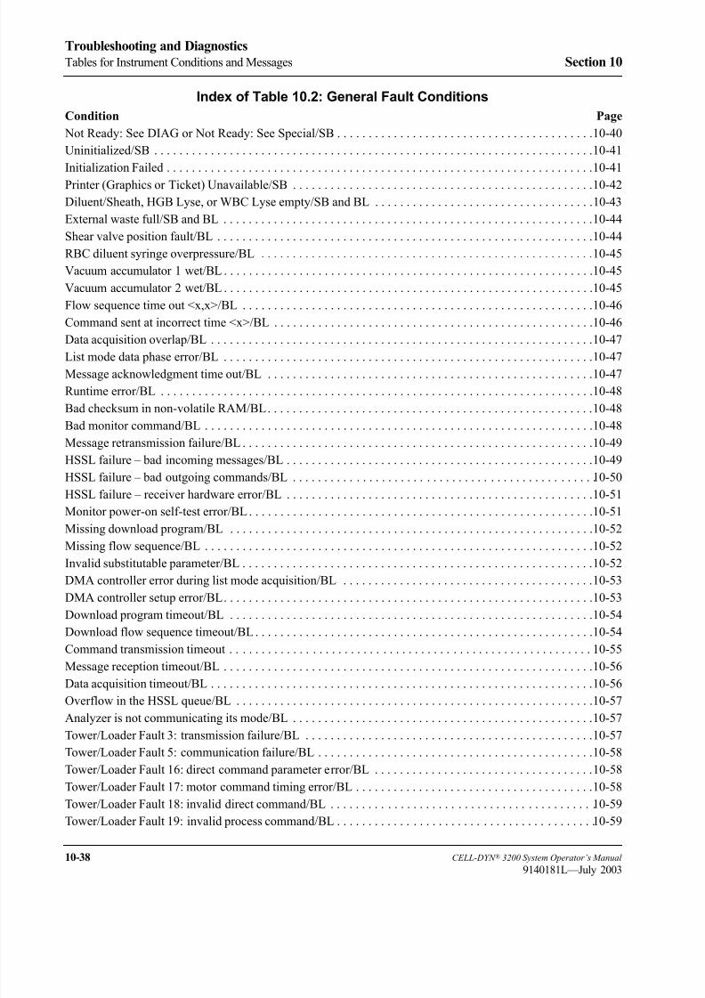
8/21/2019 Equ22-14 CellDyn3200 Op Man
http://slidepdf.com/reader/full/equ22-14-celldyn3200-op-man 480/690
10-38 CELL-DYN ® 3200 System Operator’s Manual
9140181L—July 2003
Troubleshooting and Diagnostics
Tables for Instrument Conditions and Messages Section 10
Index of Table 10.2: General Fault Conditions
Condition Page
Not Ready: See DIAG or Not Ready: See Special/SB . . . . . . . . . . . . . . . . . . . . . . . . . . . . . . . . . . . . . . . . . 10-40
Uninitialized/SB . . . . . . . . . . . . . . . . . . . . . . . . . . . . . . . . . . . . . . . . . . . . . . . . . . . . . . . . . . . . . . . . . . . . . . 10-41
Initialization Failed . . . . . . . . . . . . . . . . . . . . . . . . . . . . . . . . . . . . . . . . . . . . . . . . . . . . . . . . . . . . . . . . . . . . 10-41
Printer (Graphics or Ticket) Unavailable/SB . . . . . . . . . . . . . . . . . . . . . . . . . . . . . . . . . . . . . . . . . . . . . . . . 10-42
Diluent/Sheath, HGB Lyse, or WBC Lyse empty/SB and BL . . . . . . . . . . . . . . . . . . . . . . . . . . . . . . . . . . . 10-43
External waste full/SB and BL . . . . . . . . . . . . . . . . . . . . . . . . . . . . . . . . . . . . . . . . . . . . . . . . . . . . . . . . . . . 10-44
Shear valve position fault/BL . . . . . . . . . . . . . . . . . . . . . . . . . . . . . . . . . . . . . . . . . . . . . . . . . . . . . . . . . . . . 10-44
RBC diluent syringe overpressure/BL . . . . . . . . . . . . . . . . . . . . . . . . . . . . . . . . . . . . . . . . . . . . . . . . . . . . . 10-45
Vacuum accumulator 1 wet/BL. . . . . . . . . . . . . . . . . . . . . . . . . . . . . . . . . . . . . . . . . . . . . . . . . . . . . . . . . . . 10-45
Vacuum accumulator 2 wet/BL. . . . . . . . . . . . . . . . . . . . . . . . . . . . . . . . . . . . . . . . . . . . . . . . . . . . . . . . . . . 10-45
Flow sequence time out <x,x>/BL . . . . . . . . . . . . . . . . . . . . . . . . . . . . . . . . . . . . . . . . . . . . . . . . . . . . . . . . 10-46
Command sent at incorrect time <x>/BL . . . . . . . . . . . . . . . . . . . . . . . . . . . . . . . . . . . . . . . . . . . . . . . . . . . 10-46
Data acquisition overlap/BL . . . . . . . . . . . . . . . . . . . . . . . . . . . . . . . . . . . . . . . . . . . . . . . . . . . . . . . . . . . . . 10-47
List mode data phase error/BL . . . . . . . . . . . . . . . . . . . . . . . . . . . . . . . . . . . . . . . . . . . . . . . . . . . . . . . . . . . 10-47
Message acknowledgment time out/BL . . . . . . . . . . . . . . . . . . . . . . . . . . . . . . . . . . . . . . . . . . . . . . . . . . . . 10-47
Runtime error/BL . . . . . . . . . . . . . . . . . . . . . . . . . . . . . . . . . . . . . . . . . . . . . . . . . . . . . . . . . . . . . . . . . . . . . 10-48
Bad checksum in non-volatile RAM/BL. . . . . . . . . . . . . . . . . . . . . . . . . . . . . . . . . . . . . . . . . . . . . . . . . . . . 10-48
Bad monitor command/BL . . . . . . . . . . . . . . . . . . . . . . . . . . . . . . . . . . . . . . . . . . . . . . . . . . . . . . . . . . . . . . 10-48
Message retransmission failure/BL. . . . . . . . . . . . . . . . . . . . . . . . . . . . . . . . . . . . . . . . . . . . . . . . . . . . . . . . 10-49
HSSL failure – bad incoming messages/BL . . . . . . . . . . . . . . . . . . . . . . . . . . . . . . . . . . . . . . . . . . . . . . . . . 10-49
HSSL failure – bad outgoing commands/BL . . . . . . . . . . . . . . . . . . . . . . . . . . . . . . . . . . . . . . . . . . . . . . . .10-50
HSSL failure – receiver hardware error/BL . . . . . . . . . . . . . . . . . . . . . . . . . . . . . . . . . . . . . . . . . . . . . . . . . 10-51
Monitor power-on self-test error/BL. . . . . . . . . . . . . . . . . . . . . . . . . . . . . . . . . . . . . . . . . . . . . . . . . . . . . . . 10-51
Missing download program/BL . . . . . . . . . . . . . . . . . . . . . . . . . . . . . . . . . . . . . . . . . . . . . . . . . . . . . . . . . . 10-52
Missing flow sequence/BL . . . . . . . . . . . . . . . . . . . . . . . . . . . . . . . . . . . . . . . . . . . . . . . . . . . . . . . . . . . . . . 10-52
Invalid substitutable parameter/BL . . . . . . . . . . . . . . . . . . . . . . . . . . . . . . . . . . . . . . . . . . . . . . . . . . . . . . . . 10-52
DMA controller error during list mode acquisition/BL . . . . . . . . . . . . . . . . . . . . . . . . . . . . . . . . . . . . . . . . 10-53
DMA controller setup error/BL. . . . . . . . . . . . . . . . . . . . . . . . . . . . . . . . . . . . . . . . . . . . . . . . . . . . . . . . . . . 10-53
Download program timeout/BL . . . . . . . . . . . . . . . . . . . . . . . . . . . . . . . . . . . . . . . . . . . . . . . . . . . . . . . . . . 10-54
Download flow sequence timeout/BL. . . . . . . . . . . . . . . . . . . . . . . . . . . . . . . . . . . . . . . . . . . . . . . . . . . . . . 10-54
Command transmission timeout . . . . . . . . . . . . . . . . . . . . . . . . . . . . . . . . . . . . . . . . . . . . . . . . . . . . . . . . . .10-55
Message reception timeout/BL . . . . . . . . . . . . . . . . . . . . . . . . . . . . . . . . . . . . . . . . . . . . . . . . . . . . . . . . . . . 10-56
Data acquisition timeout/BL . . . . . . . . . . . . . . . . . . . . . . . . . . . . . . . . . . . . . . . . . . . . . . . . . . . . . . . . . . . . . 10-56
Overflow in the HSSL queue/BL . . . . . . . . . . . . . . . . . . . . . . . . . . . . . . . . . . . . . . . . . . . . . . . . . . . . . . . . . 10-57Analyzer is not communicating its mode/BL . . . . . . . . . . . . . . . . . . . . . . . . . . . . . . . . . . . . . . . . . . . . . . . . 10-57
Tower/Loader Fault 3: transmission failure/BL . . . . . . . . . . . . . . . . . . . . . . . . . . . . . . . . . . . . . . . . . . . . . . 10-57
Tower/Loader Fault 5: communication failure/BL . . . . . . . . . . . . . . . . . . . . . . . . . . . . . . . . . . . . . . . . . . . . 10-58
Tower/Loader Fault 16: direct command parameter error/BL . . . . . . . . . . . . . . . . . . . . . . . . . . . . . . . . . . . 10-58
Tower/Loader Fault 17: motor command timing error/BL . . . . . . . . . . . . . . . . . . . . . . . . . . . . . . . . . . . . . . 10-58
Tower/Loader Fault 18: invalid direct command/BL . . . . . . . . . . . . . . . . . . . . . . . . . . . . . . . . . . . . . . . . . .10-59
Tower/Loader Fault 19: invalid process command/BL. . . . . . . . . . . . . . . . . . . . . . . . . . . . . . . . . . . . . . . . .10-59

8/21/2019 Equ22-14 CellDyn3200 Op Man
http://slidepdf.com/reader/full/equ22-14-celldyn3200-op-man 481/690
CELL-DYN ® 3200 System Operator’s Manual 10-39
9140181L—July 2003
Section 10 Troubleshooting and Diagnostics
Loader Fault 40: mix head stuck in angle position/BL. . . . . . . . . . . . . . . . . . . . . . . . . . . . . . . . . . . . . . . . . 10-60
Loader Fault 41: mix head stuck in vertical position/BL . . . . . . . . . . . . . . . . . . . . . . . . . . . . . . . . . . . . . . . 10-60
Loader Fault 42: mix head not at top position/BL . . . . . . . . . . . . . . . . . . . . . . . . . . . . . . . . . . . . . . . . . . . . 10-61
Loader Fault 43: mix head stuck at top position/BL . . . . . . . . . . . . . . . . . . . . . . . . . . . . . . . . . . . . . . . . . . 10-61
Loader Fault 44: load zone empty detector malfunction . . . . . . . . . . . . . . . . . . . . . . . . . . . . . . . . . . . . . . . 10-62
Loader Fault 45: unload zone full detector malfunction/BL . . . . . . . . . . . . . . . . . . . . . . . . . . . . . . . . . . . . 10-62
Loader Fault 46: unload zone nearly full detector malfunction/BL . . . . . . . . . . . . . . . . . . . . . . . . . . . . . . . 10-63
Loader Fault 47: tube stuck in position 3/BL . . . . . . . . . . . . . . . . . . . . . . . . . . . . . . . . . . . . . . . . . . . . . . . . 10-64
Loader Fault 48: tube stuck in position 4/BL . . . . . . . . . . . . . . . . . . . . . . . . . . . . . . . . . . . . . . . . . . . . . . . . 10-66
Tower Fault 49: tower cover open/BL . . . . . . . . . . . . . . . . . . . . . . . . . . . . . . . . . . . . . . . . . . . . . . . . . . . . . 10-67
Tower Fault 50: probe stuck at home position/BL . . . . . . . . . . . . . . . . . . . . . . . . . . . . . . . . . . . . . . . . . . . . 10-68
Tower Fault 100: probe unable to reach home position/BL . . . . . . . . . . . . . . . . . . . . . . . . . . . . . . . . . . . . . 10-68
Tower Fault 141: invalid tube height/BL . . . . . . . . . . . . . . . . . . . . . . . . . . . . . . . . . . . . . . . . . . . . . . . . . . . 10-69
Tower Fault 142: no tube present/BL . . . . . . . . . . . . . . . . . . . . . . . . . . . . . . . . . . . . . . . . . . . . . . . . . . . . . . 10-70
Loader Warning 144: excessive cycling/BL . . . . . . . . . . . . . . . . . . . . . . . . . . . . . . . . . . . . . . . . . . . . . . . . . 10-71
Loader Fault 147: unload area hardware malfunction/BL . . . . . . . . . . . . . . . . . . . . . . . . . . . . . . . . . . . . . . 10-72
Loader Fault 148: tube dropped during mixing/BL . . . . . . . . . . . . . . . . . . . . . . . . . . . . . . . . . . . . . . . . . . . 10-73
Loader Fault 149: mix zone rack position error/BL . . . . . . . . . . . . . . . . . . . . . . . . . . . . . . . . . . . . . . . . . . . 10-74
Loader Fault 150: unexpected tube in position 4 after rack advance/BL . . . . . . . . . . . . . . . . . . . . . . . . . . . 10-75
Loader Fault 151: tube lost moving from position 3 to 4/BL. . . . . . . . . . . . . . . . . . . . . . . . . . . . . . . . . . . . 10-76
Loader Fault 152: mix zone must be cleared for reset/BL . . . . . . . . . . . . . . . . . . . . . . . . . . . . . . . . . . . . . . 10-77
Loader Fault 153: rack bar code read failure/BL . . . . . . . . . . . . . . . . . . . . . . . . . . . . . . . . . . . . . . . . . . . . . 10-78
Loader Fault 154: tube position bar code read failure/BL . . . . . . . . . . . . . . . . . . . . . . . . . . . . . . . . . . . . . . 10-79
Loader Fault 156: bar code reader failure/BL . . . . . . . . . . . . . . . . . . . . . . . . . . . . . . . . . . . . . . . . . . . . . . . 10-80

8/21/2019 Equ22-14 CellDyn3200 Op Man
http://slidepdf.com/reader/full/equ22-14-celldyn3200-op-man 482/690
10-40 CELL-DYN ® 3200 System Operator’s Manual
9140181L—July 2003
Troubleshooting and Diagnostics
Tables for Instrument Conditions and Messages Section 10
Table 10.2 General Fault Conditions
Each message is followed by one of the abbreviations shown below indicating
where that message appears on the screen:
BL — Bulletin Line
SB — Status Box
Information for each message is listed in order from the most likely cause of the
message to the least likely cause of the message. Therefore, always troubleshoot
a problem in this order. If a problem cannot be resolved by the corrective action
indicated in this table, call for technical assistance.
Not Ready: See DIAG or Not Ready: See Special/SB
If a fault condition has occurred, the FAULT indicator light on the Analyzer
status indicator panel is illuminated in red.
– – – – Probable Cause – – – – – – – – Corrective Action – – –
1. A situation that prevents the
READY state has been detected. See
the DIAGNOSTICS MENU screen or
the SPECIAL PROTOCOLS MENU
screen,
whichever is indicated, for
more information.
1. From the first DIAGNOSTICS MENU
screen, press [FAULT REPORT] followed by [PRINT] to obtain a
printout describing the problem.
Refer to the appropriate table for
corrective action.
2. A diagnostic test was run using one
of the DIAGNOSTICS MENU screen
keys.
2. The instrument must be initialized
when the diagnostic test in progress
is finished. Initialize the Analyzer
by pressing the [INITIALIZATION] key on the second DIAGNOSTICS
MENU screen.
3. A Special Protocols procedure is in
progress.
3. Check the SPECIAL PROTOCOLSMENU screen and perform the
action necessary to complete the
procedure.
4. System malfunction. 4. If the message occurs repeatedly,
contact Abbott Customer Service.

8/21/2019 Equ22-14 CellDyn3200 Op Man
http://slidepdf.com/reader/full/equ22-14-celldyn3200-op-man 483/690
CELL-DYN ® 3200 System Operator’s Manual 10-41
9140181L—July 2003
Section 10 Troubleshooting and Diagnostics
Uninitialized/SB
– – – – Probable Cause – – – – – – – – Corrective Action – – –
1. Main power switch is ON but the
Analyzer is not responding.
1. Turn the system OFF.
2. Ensure that all cables on the back of
the instrument are properly
attached.
3. Turn the System ON.
4. If the problem persists, contact
Abbott Customer Service.
Initialization Failed
Bottom of screen (MAIN MENU is not displayed)
– – – – Probable Cause – – – – – – – – Corrective Action – – –
1. The instrument software was unable
to initialize. The CELL-DYN
software does not display the MAINMENU screen.
1. Initialize the Analyzer by following
the instructions in the Power OFF
and Power ON procedures given in
Section 5: Operating Instructions;
Subsection: Operation Overview.
If the Analyzer does not initialize,
press the Print Screen key on the
computer keyboard to document
any screen messages, then contact
Abbott Customer Service.
Table 10.2 General Fault Conditions (Continued)

8/21/2019 Equ22-14 CellDyn3200 Op Man
http://slidepdf.com/reader/full/equ22-14-celldyn3200-op-man 484/690
10-42 CELL-DYN ® 3200 System Operator’s Manual
9140181H—October 2001
Troubleshooting and Diagnostics
Tables for Instrument Conditions and Messages Section 10
Printer (Graphics or Ticket) Unavailable/SB
– – – - Probable Cause – – – – – – – - Corrective Action – – –
1. The print buffer (the memory area
where the information is stored
while awaiting printing) is full.
1. Press the [STOP PRINTING] key on
the CUSTOMIZE PRINTED REPORT
screen for the appropriate printer.
2. The printer is turned OFF. 2. Turn the printer power switch ON.
3. The printer is not on-line. 3. Check that the printer “on-line”
indicator is illuminated. If
necessary, refer to the printer
manual for assistance.
4. The power cord is loose or
disconnected. The interface cable is
loose or disconnected.
4. Check the power cable connection
on the printer and power outlet.
Make sure the connections aresecure. Check the interface cable
connectors on the printer and
Analyzer. Make sure the
connections are secure. Press
[PRINT REPORT]. If the message is
still displayed, turn the printer
power switch OFF and ON to reset
the printer.
5. Printer cable is connected to the
wrong port.
5. Ensure that the graphics printer
cable is attached to the graphics
printer port (LPT1) and the ticket
printer cable is attached to the ticket
printer port (LPT2).
Table 10.2 General Fault Conditions (Continued)

8/21/2019 Equ22-14 CellDyn3200 Op Man
http://slidepdf.com/reader/full/equ22-14-celldyn3200-op-man 485/690
CELL-DYN ® 3200 System Operator’s Manual 10-43
9140181L—July 2003
Section 10 Troubleshooting and Diagnostics
Diluent/Sheath, HGB Lyse, or WBC Lyse empty/SB and BL
– – – - Probable Cause – – – – – – – - Corrective Action – – –
1. Container is empty. 1. Install a new container of reagent.
Press [CLEAR FAULT]. Run 5 or
more background counts and
review results.
NOTE: Do not pour any remaining reagent into the new container.
2. Reagent inlet tubing is crimped or
obstructed.
2. Inspect the whole length of the inlet
tubing to ensure it is not crimped
and/or remove any obstruction.
3. Reagent line is not on the bottom of
the container.
3. Ensure that the line is properly
inserted in the container and the
sinker is on the bottom of thecontainer.
4. An incorrect reagent or a
nonconductive liquid is connected to
the inlet tube.
4. Check the label on the reagent
container to be sure the correct
reagent is installed. Trace the line to
the inlet connector and ensure that it
is connected to the correct one.
Check the connection to be sure it is
secure and then press [CLEARFAULT].
5. Appropriate syringe not mounted
properly.
5. Check proper mounting of syringes.
6. The Luer fitting connection on the
top of the appropriate syringe is
loose.
6. Verify the Luer connection on the
top of syringes is secure.
7. WBC Lyse or HGB Lyse only:
tubing in solenoid valve is pinched
or not fully inserted.
7a.Check tubing in N/C valves 23
(WBC Lyse) or 28 (HGB Lyse) is
not pinched or obstructed; replace
as necessary.
7b.Verify tubings are fully inserted in
solenoids 23, 25 (WBC Lyse) and
28, 24 (HGB Lyse).
8. Circuitry malfunction. 8. Contact Abbott Customer Service.
Table 10.2 General Fault Conditions (Continued)

8/21/2019 Equ22-14 CellDyn3200 Op Man
http://slidepdf.com/reader/full/equ22-14-celldyn3200-op-man 486/690
10-44 CELL-DYN ® 3200 System Operator’s Manual
9140181L—July 2003
Troubleshooting and Diagnostics
Tables for Instrument Conditions and Messages Section 10
External waste full/SB and BL
– – – - Probable Cause – – – – – – – - Corrective Action – – –
1. Waste container full. 1. Empty the waste container and/or
replace it. Press [CLEAR FAULT] to resume operation.
NOTE: Make sure the Analyzer
rinse process has been
completed before
removing the waste tube.
2. Waste sensor connector is loose or
disconnected.
2. Reconnect the waste sensor
connector and then press [CLEARFAULT].
3. Shorted wire(s) or electrode(s) on
the waste cap.
3. Visually inspect wires and
electrodes and call for technical
assistance.
4. Circuitry malfunction. 4. If the message appears repeatedly,
contact Abbott Customer Service.
Shear valve position fault/BL
– – – - Probable Cause – – – – – – – - Corrective Action – – –
1. The Shear Valve did not rotate
properly or in the allotted time.
1. Clean the Shear Valve. Then,
initialize the Analyzer by pressing
the [INITIALIZATION] key on the
second DIAGNOSTICS MENU screen. If the message appears
again, reboot the system. NOTE: If
you wish to use the Sample Loader,
reset the racks before initializing or
rebooting the System.
2. Sensor or cable malfunction. 2. If the problem occurs repeatedly,
contact Abbott Customer Service.
Table 10.2 General Fault Conditions (Continued)

8/21/2019 Equ22-14 CellDyn3200 Op Man
http://slidepdf.com/reader/full/equ22-14-celldyn3200-op-man 487/690
CELL-DYN ® 3200 System Operator’s Manual 10-45
9140181L—July 2003
Section 10 Troubleshooting and Diagnostics
RBC diluent syringe overpressure/BL
NOTE: Diluent/Sheath syringe attempted to move up and pressure exceeding
the allowed limit was detected in the Diluent/Sheath line.
– – – - Probable Cause – – – – – – – - Corrective Action – – –
1. A blockage obstructs the Diluent/
Sheath reagent distribution through
the flow system.
1. Try to initialize the system.
2. If you cannot open Right Front
Cover/Door contact Abbott
Customer Service.
3. If you can open the Right Front
Cover/Door, remove the Diluent/
Sheath and WBC Lyse syringesfrom their brackets (make sure the
syringes stay connected to the Luer
fittings) and initialize the Analyzer.
4. Clean the 10 mL syringe.
5. Clean the Shear Valve.
6. Verify tubing in solenoids 26 and 27
is not pinched; replace if necessary.
7. If still unable to resolve the
problem, contact Abbott CustomerService.
Vacuum accumulator 1 wet/BL
Vacuum accumulator 2 wet/BL
– – – - Probable Cause – – – – – – – - Corrective Action – – –
1. The internal vacuum accumulator
has filled with liquid beyond
allowable limits.
1. From the second DIAGNOSTICSMENU screen, press the [DRAIN
ACCUMULAT] key. When the cycle
is finished, initialize the Analyzer
by pressing the [INITIALIZATION] key on the second DIAGNOSTICSMENU screen. If the fault recurs,
repeat this action. If the fault
persists, contact Abbott Customer
Service.
Table 10.2 General Fault Conditions (Continued)

8/21/2019 Equ22-14 CellDyn3200 Op Man
http://slidepdf.com/reader/full/equ22-14-celldyn3200-op-man 488/690
10-46 CELL-DYN ® 3200 System Operator’s Manual
9140181L—July 2003
Troubleshooting and Diagnostics
Tables for Instrument Conditions and Messages Section 10
Flow sequence time out <x,x>/BL
NOTE: Characters in the brackets identify the problem flow sequence number
and name.
– – – - Probable Cause – – – – – – – - Corrective Action – – –
1. An internal Analyzer flow sequence
was not completed in the allotted
time.
1. Record the characters in the
brackets.
2. Initialize the Analyzer by pressing
the [INITIALIZATION] key on the
second DIAGNOSTICS MENU
screen. Continue processing
samples.
3. If the problem recurs, contactAbbott Customer Service.
Command sent at incorrect time <x>/BL
– – – - Probable Cause – – – – – – – - Corrective Action – – –
1. The Analyzer received a command
from the System Software at the
incorrect time and could not process
it.
1. Record the characters in the
brackets.
2. Initialize the Analyzer by pressing
the [INITIALIZATION] key on the
second DIAGNOSTICS MENU
screen. Continue processing
samples.
3. If the problem recurs, contact
Abbott Customer Service.
Table 10.2 General Fault Conditions (Continued)

8/21/2019 Equ22-14 CellDyn3200 Op Man
http://slidepdf.com/reader/full/equ22-14-celldyn3200-op-man 489/690
CELL-DYN ® 3200 System Operator’s Manual 10-47
9140181L—July 2003
Section 10 Troubleshooting and Diagnostics
Data acquisition overlap/BL
The error may occur when several tasks are requested in rapid sequence. For
example, print data log, transmit result, sample processing, print ticket, print
report, etc.
– – – - Probable Cause – – – – – – – - Corrective Action – – –
1. The timing of communication
between the Analyzer and the
System Software is incorrect.
1. Record what happened when the
message was displayed.
2. Initialize the Analyzer by pressing
the [INITIALIZATION] key on the
second DIAGNOSTICS MENU screen.
Continue processing samples.
3. If the fault recurs, contact AbbottCustomer Service.
List mode data phase error/BL
– – – - Probable Cause – – – – – – – - Corrective Action – – –
1. The order of the data received for
display on the screen was incorrect.
1. Record what happened when the
message was displayed.
2. Initialize the Analyzer by pressing
the [INITIALIZATION] key on the
second DIAGNOSTICS MENU screen.
Continue processing samples.
3. If the fault recurs, contact Abbott
Customer Service.
Message acknowledgment time out/BL
– – – - Probable Cause – – – – – – – - Corrective Action – – –
1. Communication between the
Analyzer and the Data Module did
not occur when expected.
1. Record what happened when the
message was displayed.
2. Initialize the Analyzer by pressing
the [INITIALIZATION] key on thesecond DIAGNOSTIC MENU screen.
Continue processing samples.
If the fault recurs, contact Abbott
Customer Service.
Table 10.2 General Fault Conditions (Continued)

8/21/2019 Equ22-14 CellDyn3200 Op Man
http://slidepdf.com/reader/full/equ22-14-celldyn3200-op-man 490/690
10-48 CELL-DYN ® 3200 System Operator’s Manual
9140181L—July 2003
Troubleshooting and Diagnostics
Tables for Instrument Conditions and Messages Section 10
Runtime error/BL
– – – - Probable Cause – – – – – – – - Corrective Action – – –
1. An illegal software operation was
requested by the Analyzer.
1. Record what happened when the
message was displayed.
2. Initialize the Analyzer by pressing
the [INITIALIZATION] key on the
second DIAGNOSTICS MENU
screen. Continue processing
samples. If the fault recurs, contact
Abbott Customer Service.
Bad checksum in non-volatile RAM/BL
– – – - Probable Cause – – – – – – – - Corrective Action – – –
1. When the system was powered ON,the Analyzer did not transmit the
correct message to the Data Module.
1. Power OFF and ON again.
2. If the fault recurs, contact Abbott
Customer Service.
Bad monitor command/BL
NOTE: This message pertains to a software execution monitor on the Analyzer,
not the video display screen (CRT).
– – – - Probable Cause – – – – – – – - Corrective Action – – –
1. During the initialization process, the
Data Module and Analyzer did not
communicate properly.
1. Initialize the Analyzer by pressing
the [INITIALIZATION] key on the
secondDIAGNOSTICS MENU screen.
If the fault recurs, power OFF and
ON again. Contact Abbott
Customer Service if the message
appears repeatedly.
Table 10.2 General Fault Conditions (Continued)

8/21/2019 Equ22-14 CellDyn3200 Op Man
http://slidepdf.com/reader/full/equ22-14-celldyn3200-op-man 491/690
CELL-DYN ® 3200 System Operator’s Manual 10-49
9140181L—July 2003
Section 10 Troubleshooting and Diagnostics
Message retransmission failure/BL
Communication from the Data Module to the Analyzer failed.
– – – - Probable Cause – – – – – – – - Corrective Action – – –
1. A hardware failure or system error
has occurred.
1. Initialize the Analyzer by pressing
the [INITIALIZATION] key on the
second DIAGNOSTICS MENU
screen. If the message appears
again, reboot the System.
NOTE: If you wish to use the
Sample Loader, reset the
racks before initializing or
rebooting the System.
2. If the message appears repeatedly,
contact Abbott Customer Service.
HSSL failure – bad incoming messages/BL
NOTE: HSSL stands for High Speed Serial Link.
The Data Module received unrecognizable messages from the Analyzer.
– – – - Probable Cause – – – – – – - Corrective Action –
1. The communication line has become
noisy, possibly due to a partial break
in the line.
1. Initialize the Analyzer by pressing
the [INITIALIZATION] key on the
second DIAGNOSTICS MENU
screen. If the message appearsagain, power OFF the Analyzer.
Then reseat both ends of HSSL
cable and make sure the
connections are secure. Power
Analyzer ON.
NOTE: For the location of the
HSSL connectors on the
rear panel of the Data
Module, refer to Section
1: Use or Function;
Subsection: Data Module
Components.
NOTE: If you wish to use the
Sample Loader, reset the
racks before initializing or
rebooting the System.
2. If the message appears repeatedly,
contact Abbott Customer Service.
Table 10.2 General Fault Conditions (Continued)
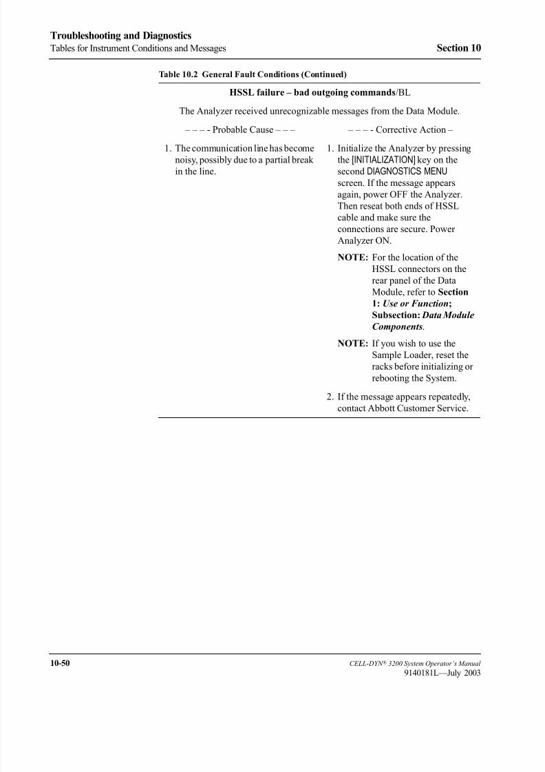
8/21/2019 Equ22-14 CellDyn3200 Op Man
http://slidepdf.com/reader/full/equ22-14-celldyn3200-op-man 492/690
10-50 CELL-DYN ® 3200 System Operator’s Manual
9140181L—July 2003
Troubleshooting and Diagnostics
Tables for Instrument Conditions and Messages Section 10
HSSL failure – bad outgoing commands/BL
The Analyzer received unrecognizable messages from the Data Module.
– – – - Probable Cause – – – – – – - Corrective Action –
1. The communication line has become
noisy, possibly due to a partial break
in the line.
1. Initialize the Analyzer by pressing
the [INITIALIZATION] key on the
second DIAGNOSTICS MENU
screen. If the message appears
again, power OFF the Analyzer.
Then reseat both ends of HSSL
cable and make sure the
connections are secure. Power
Analyzer ON.
NOTE: For the location of the
HSSL connectors on therear panel of the Data
Module, refer to Section
1: Use or Function;
Subsection: Data Module
Components.
NOTE: If you wish to use the
Sample Loader, reset the
racks before initializing or
rebooting the System.
2. If the message appears repeatedly,
contact Abbott Customer Service.
Table 10.2 General Fault Conditions (Continued)

8/21/2019 Equ22-14 CellDyn3200 Op Man
http://slidepdf.com/reader/full/equ22-14-celldyn3200-op-man 493/690
CELL-DYN ® 3200 System Operator’s Manual 10-51
9140181L—July 2003
Section 10 Troubleshooting and Diagnostics
HSSL failure – receiver hardware error/BL
The HSSL receiver on the Data Module malfunctioned.
– – – - Probable Cause – – – – – – - Corrective Action –
1. A hardware failure on the HSSL
card has occurred.
1. Initialize the Analyzer by pressing
the [INITIALIZATION] key on the
second DIAGNOSTICS MENU
screen. If the message appears
again, power OFF the Analyzer.
Then reseat both ends of HSSL
cable and make sure the
connections are secure. Power
Analyzer ON.
NOTE: For the location of the
HSSL connectors on therear panel of the Data
Module, refer to Section
1: Use or Function;
Subsection: Data Module
Components.
NOTE: If you wish to use the
Sample Loader, reset the
racks before initializing or
rebooting the System.
2. If the message appears repeatedly,
contact Abbott Customer Service.
Monitor power-on self-test error/BL
NOTE: This message pertains to a software execution monitor on the Analyzer,
not the video display monitor.
A failure occurred during self-test.
(e.g., test pattern not successfully read from memory)
– – – - Probable Cause – – – – – – - Corrective Action –
1. A failure in the Analyzer hardware
has occurred.
1. Reboot the System.
NOTE: If you wish to use theSample Loader, reset the
racks before rebooting the
System.
2. If the message appears repeatedly,
contact Abbott Customer Service.
Table 10.2 General Fault Conditions (Continued)

8/21/2019 Equ22-14 CellDyn3200 Op Man
http://slidepdf.com/reader/full/equ22-14-celldyn3200-op-man 494/690
10-52 CELL-DYN ® 3200 System Operator’s Manual
9140181L—July 2003
Troubleshooting and Diagnostics
Tables for Instrument Conditions and Messages Section 10
Missing download program/BL
Download program not present on Data Module.
– – – - Probable Cause – – – – – – - Corrective Action –
1. Installation error, damaged hard
disk, or erased hard disk.
1. Reboot the System.
NOTE: If you wish to use the
Sample Loader, reset the
racks before rebooting the
System.
2. If the message appears repeatedly,
contact Abbott Customer Service.
Missing flow sequence/BL
Flow sequence not present on Data Module.
– – – - Probable Cause – – – – – – - Corrective Action –
1. Installation error, damaged hard
disk, or erased hard disk.
1. Reboot the System.
NOTE: If you wish to use the
Sample Loader, reset the
racks before rebooting the
System.
2. If the message appears repeatedly,
contact Abbott Customer Service.
Invalid substitutable parameter/BL
Size or structure of parameter (e.g., gain) is invalid.
– – – - Probable Cause – – – – – – - Corrective Action –
1. A software error has occurred. 1. Reboot the System.
NOTE: If you wish to use the
Sample Loader, reset the
racks before rebooting the
System.
2. If the message appears repeatedly,
contact Abbott Customer Service.
Table 10.2 General Fault Conditions (Continued)

8/21/2019 Equ22-14 CellDyn3200 Op Man
http://slidepdf.com/reader/full/equ22-14-celldyn3200-op-man 495/690
CELL-DYN ® 3200 System Operator’s Manual 10-53
9140181L—July 2003
Section 10 Troubleshooting and Diagnostics
DMA controller error during list mode acquisition/BL
NOTE: DMA stands for Direct Memory Access.
A memory access control problem occurred during data acquisition.
– – – - Probable Cause – – – – – – - Corrective Action –
1. A failure in the Analyzer hardware
has occurred.
1. Initialize the Analyzer by pressing
the [INITIALIZATION] key on the
second DIAGNOSTICS MENU
screen. If the message appears
again, reboot the System.
NOTE: If you wish to use the
Sample Loader, reset the
racks before initializing or
rebooting the System.
2. If the message appears repeatedly,
contact Abbott Customer Service.
DMA controller setup error/BL
A problem occurred during setup of the memory access controller.
– – – - Probable Cause – – – – – – - Corrective Action –
1. A failure in the Analyzer hardware
has occurred.
1. Initialize the Analyzer by pressing
the [INITIALIZATION] key on the
second DIAGNOSTICS MENU
screen. If the message appearsagain, reboot the System.
NOTE: If you wish to use the
Sample Loader, reset the
racks before initializing or
rebooting the System.
2. If the message appears repeatedly,
contact Abbott Customer Service.
Table 10.2 General Fault Conditions (Continued)

8/21/2019 Equ22-14 CellDyn3200 Op Man
http://slidepdf.com/reader/full/equ22-14-celldyn3200-op-man 496/690
10-54 CELL-DYN ® 3200 System Operator’s Manual
9140181L—July 2003
Troubleshooting and Diagnostics
Tables for Instrument Conditions and Messages Section 10
Download program timeout/BL
The allotted time for program downloading was exceeded.
– – – - Probable Cause – – – – – – - Corrective Action –
1. A failure in the Analyzer hardware,
possibly related to the HSSL cable,
card, or memory, has occurred.
1. Check the HSSL cable connections.
Then, initialize the Analyzer by
pressing the [INITIALIZATION] key
on the second DIAGNOSTICS MENU
screen. If the message appears
again, reboot the System.
NOTE: For the location of the
HSSL ports, refer to
Section 1: Use or
Function; Subsection:
Data ModuleComponents.
NOTE: If you wish to use the
Sample Loader, reset the
racks before initializing or
rebooting the System.
2. If the message appears repeatedly,
contact Abbott Customer Service.
Download flow sequence timeout/BL
The allotted time for flow sequence downloading was exceeded.
– – – - Probable Cause – – – – – – - Corrective Action –
1. The flow sequence did not compile,
possibly due to interruption by a
fatal fault, an improperly seated
Tower Cover or door, or a fluidics
problem.
1. Reboot the System.
NOTE: If you wish to use the
Sample Loader, reset the
racks before rebooting the
System.
2. If the message appears repeatedly,
contact Abbott Customer Service.
Table 10.2 General Fault Conditions (Continued)

8/21/2019 Equ22-14 CellDyn3200 Op Man
http://slidepdf.com/reader/full/equ22-14-celldyn3200-op-man 497/690
CELL-DYN ® 3200 System Operator’s Manual 10-55
9140181L—July 2003
Section 10 Troubleshooting and Diagnostics
Command transmission timeout
The Data Module did not receive acknowledgment of a command sent to the
Analyzer within the allotted time.
– – – - Probable Cause – – – – – – - Corrective Action –
1. A failure in the Analyzer hardware,
possibly due to an unplugged or
damaged HSSL cable, has occurred.
1. Check the HSSL cable connections.
Then, initialize the Analyzer by
pressing the [INITIALIZATION] key
on the second DIAGNOSTICS MENU
screen. If the message appears
again, reboot the System.
NOTE: For the location of the
HSSL ports, refer to
Section 1: Use or
Function; Subsection: Data Module
Components.
NOTE: If you wish to use the
Sample Loader, reset the
racks before initializing or
rebooting the System.
2. A software error has occurred. 2. If the message appears repeatedly,
contact Abbott Customer Service.
Table 10.2 General Fault Conditions (Continued)
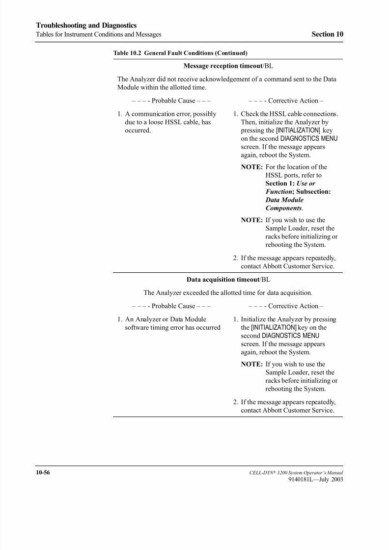
8/21/2019 Equ22-14 CellDyn3200 Op Man
http://slidepdf.com/reader/full/equ22-14-celldyn3200-op-man 498/690
10-56 CELL-DYN ® 3200 System Operator’s Manual
9140181L—July 2003
Troubleshooting and Diagnostics
Tables for Instrument Conditions and Messages Section 10
Message reception timeout/BL
The Analyzer did not receive acknowledgement of a command sent to the Data
Module within the allotted time.
– – – - Probable Cause – – – – – – - Corrective Action –
1. A communication error, possibly
due to a loose HSSL cable, has
occurred.
1. Check the HSSL cable connections.
Then, initialize the Analyzer by
pressing the [INITIALIZATION] key
on the second DIAGNOSTICS MENU
screen. If the message appears
again, reboot the System.
NOTE: For the location of the
HSSL ports, refer to
Section 1: Use or
Function; Subsection: Data Module
Components.
NOTE: If you wish to use the
Sample Loader, reset the
racks before initializing or
rebooting the System.
2. If the message appears repeatedly,
contact Abbott Customer Service.
Data acquisition timeout/BL
The Analyzer exceeded the allotted time for data acquisition.
– – – - Probable Cause – – – – – – - Corrective Action –
1. An Analyzer or Data Module
software timing error has occurred
1. Initialize the Analyzer by pressing
the [INITIALIZATION] key on the
second DIAGNOSTICS MENU
screen. If the message appears
again, reboot the System.
NOTE: If you wish to use the
Sample Loader, reset the
racks before initializing or
rebooting the System.
2. If the message appears repeatedly,
contact Abbott Customer Service.
Table 10.2 General Fault Conditions (Continued)
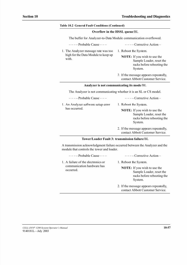
8/21/2019 Equ22-14 CellDyn3200 Op Man
http://slidepdf.com/reader/full/equ22-14-celldyn3200-op-man 499/690
CELL-DYN ® 3200 System Operator’s Manual 10-57
9140181L—July 2003
Section 10 Troubleshooting and Diagnostics
Overflow in the HSSL queue/BL
The buffer for Analyzer-to-Data Module communication overflowed.
– – – - Probable Cause – – – – – – - Corrective Action –
1. The Analyzer message rate was too
high for the Data Module to keep up
with.
1. Reboot the System.
NOTE: If you wish to use the
Sample Loader, reset the
racks before rebooting the
System.
2. If the message appears repeatedly,
contact Abbott Customer Service.
Analyzer is not communicating its mode/BL
The Analyzer is not communicating whether it is an SL or CS model.
– – – - Probable Cause – – – – – – - Corrective Action –
1. An Analyzer software setup error
has occurred.
1. Reboot the System.
NOTE: If you wish to use the
Sample Loader, reset the
racks before rebooting the
System.
2. If the message appears repeatedly,
contact Abbott Customer Service.
Tower/Loader Fault 3: transmission failure/BL
A transmission acknowledgment failure occurred between the Analyzer and the
module that controls the tower and loader.
– – – - Probable Cause – – – – – – - Corrective Action –
1. A failure of the electronics or
communication hardware has
occurred.
1. Reboot the System.
NOTE: If you wish to use the
Sample Loader, reset the
racks before rebooting the
System.
2. If the message appears repeatedly,contact Abbott Customer Service.
Table 10.2 General Fault Conditions (Continued)

8/21/2019 Equ22-14 CellDyn3200 Op Man
http://slidepdf.com/reader/full/equ22-14-celldyn3200-op-man 500/690
10-58 CELL-DYN ® 3200 System Operator’s Manual
9140181L—July 2003
Troubleshooting and Diagnostics
Tables for Instrument Conditions and Messages Section 10
Tower/Loader Fault 5: communication failure/BL
A communication failure occurred between the Analyzer and the module that
controls the tower and loader.
– – – - Probable Cause – – – – – – - Corrective Action –
1. A communication timing or
handshake error has occurred.
1. Reboot the System.
NOTE: If you wish to use the
Sample Loader, reset the
racks before rebooting the
System.
2. If the message appears repeatedly,
contact Abbott Customer Service.
Tower/Loader Fault 16: direct command parameter error/BL
The Analyzer command given to the module that controls the tower and loader
is invalid.
– – – - Probable Cause – – – – – – - Corrective Action –
1. A software error has occurred. 1. Reboot the System.
NOTE: If you wish to use the
Sample Loader, reset the
racks before rebooting the
System.
2. If the message appears repeatedly,
contact Abbott Customer Service.
Tower/Loader Fault 17: motor command timing error/BL
A motor in the Sample Loader was busy (e.g., in motion) when a command was
received and could not respond.
– – – - Probable Cause – – – – – – - Corrective Action –
1. A mechanical problem in the Tower
or Sample Loader has occurred.
1. Check for an obstruction in the
Tower or Sample Loader and, if one
is found, remove it. Reboot the
System.
NOTE: If you wish to use the
Sample Loader, reset the
racks before rebooting the
System.
2. If the message appears repeatedly,
contact Abbott Customer Service.
Table 10.2 General Fault Conditions (Continued)
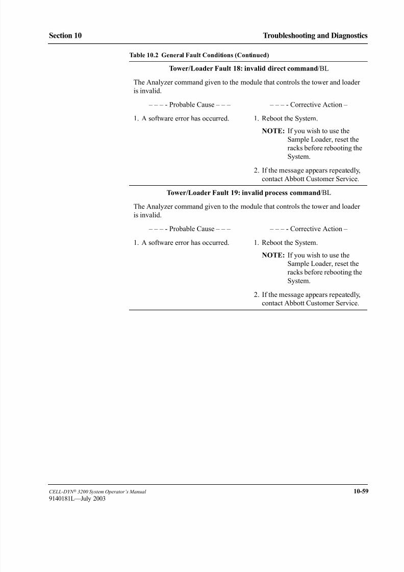
8/21/2019 Equ22-14 CellDyn3200 Op Man
http://slidepdf.com/reader/full/equ22-14-celldyn3200-op-man 501/690
CELL-DYN ® 3200 System Operator’s Manual 10-59
9140181L—July 2003
Section 10 Troubleshooting and Diagnostics
Tower/Loader Fault 18: invalid direct command/BL
The Analyzer command given to the module that controls the tower and loader
is invalid.
– – – - Probable Cause – – – – – – - Corrective Action –
1. A software error has occurred. 1. Reboot the System.
NOTE: If you wish to use the
Sample Loader, reset the
racks before rebooting the
System.
2. If the message appears repeatedly,
contact Abbott Customer Service.
Tower/Loader Fault 19: invalid process command/BL
The Analyzer command given to the module that controls the tower and loader
is invalid.
– – – - Probable Cause – – – – – – - Corrective Action –
1. A software error has occurred. 1. Reboot the System.
NOTE: If you wish to use the
Sample Loader, reset the
racks before rebooting the
System.
2. If the message appears repeatedly,
contact Abbott Customer Service.
Table 10.2 General Fault Conditions (Continued)

8/21/2019 Equ22-14 CellDyn3200 Op Man
http://slidepdf.com/reader/full/equ22-14-celldyn3200-op-man 502/690
10-60 CELL-DYN ® 3200 System Operator’s Manual
9140181L—July 2003
Troubleshooting and Diagnostics
Tables for Instrument Conditions and Messages Section 10
Loader Fault 40: mix head stuck in angle position/BL
The Mix Head failed to return to its vertical position.
– – – - Probable Cause – – – – – – - Corrective Action –
1. A mechanical problem is preventing
the Mix Head from rotating
downward.
1. Remove the Loader Cover. Check
for an obstruction that is preventing
the Mix Head from rotating
downward. If an obstruction is
found, remove it and rotate the Mix
Head to its vertical position.
Reinstall the Loader Cover, reset
the racks, and reset the Sample
Loader by pressing the following
keys in order:
[CLEAR FAULT],
[START LOADER],
[RESET LOADER].
2. A failure of the magnetic reed sensor
or related electronics has occurred.
2. If the message appears repeatedly,
contact Abbott Customer Service.
Loader Fault 41: mix head stuck in vertical position/BL
The Mix Head failed to move from its vertical position.
– – – - Probable Cause – – – – – – - Corrective Action –
1. A mechanical problem is preventing
the Mix Head from rotating upward.
1. Remove the Loader Cover. Check
for an obstruction that is preventingthe Mix Head from rotating upward
and, if one is found, remove it.
Reinstall the Loader Cover, reset
the racks, and reset the Sample
Loader by pressing the following
keys in order:
[CLEAR FAULT],
[START LOADER],
[RESET LOADER].
2. A failure of the magnetic reed sensor
or related electronics has occurred.
2. If the message appears repeatedly,
contact Abbott Customer Service.
Table 10.2 General Fault Conditions (Continued)

8/21/2019 Equ22-14 CellDyn3200 Op Man
http://slidepdf.com/reader/full/equ22-14-celldyn3200-op-man 503/690
CELL-DYN ® 3200 System Operator’s Manual 10-61
9140181L—July 2003
Section 10 Troubleshooting and Diagnostics
Loader Fault 42: mix head not at top position/BL
The Mix/Lift Assembly failed to reach its top position.
– – – - Probable Cause – – – – – – - Corrective Action –
1. A mechanical problem is preventing
Mix/Lift Assembly is from moving
upward.
1. Remove the Loader Cover. Check
for an obstruction that is preventing
the Mix/Lift Assembly from
moving upward and, if one is found,
remove it. Then, reinstall the
Loader Cover, reset the racks, and
reset the Sample Loader by
pressing the following keys in
order:
[CLEAR FAULT],
[START LOADER],
[RESET LOADER].
2. A failure of the optical sensor or
related electronics has occurred.
2. If the message appears repeatedly,
contact Abbott Customer Service.
Loader Fault 43: mix head stuck at top position/BL
The Mix/Lift Assembly failed to move from its top position.
– – – - Probable Cause – – – – – – - Corrective Action –
1. A mechanical problem is preventing
the Mix/Lift Assembly from moving
downward.
1. Remove the Loader Cover. Check
for an obstruction that is preventing
the Mix/Lift Assembly frommoving downward and, if one is
found, remove it. Then, reinstall the
Loader Cover, reset the racks, and
reset the Sample Loader by
pressing the following keys in
order:
[CLEAR FAULT],
[START LOADER],
[RESET LOADER].
2. A failure of the optical sensor or
related electronics has occurred.
2. If the message appears repeatedly,
contact Abbott Customer Service.
Table 10.2 General Fault Conditions (Continued)

8/21/2019 Equ22-14 CellDyn3200 Op Man
http://slidepdf.com/reader/full/equ22-14-celldyn3200-op-man 504/690
10-62 CELL-DYN ® 3200 System Operator’s Manual
9140181L—July 2003
Troubleshooting and Diagnostics
Tables for Instrument Conditions and Messages Section 10
Loader Fault 44: load zone empty detector malfunction
The system failed to retract mechanical arms after detecting that the load zone is
empty.
NOTE: This fault does not lead to a Sample Loader halt because any rack
currently in the mixing zone is unaffected.
– – – - Probable Cause – – – – – – - Corrective Action –
1. A mechanical problem has
prevented the rack arms in the load
zone from retracting.
1. Visually check for an obstruction
that is preventing the rack arms in
the load zone from retracting and, if
one is found, press the STOPLOADER key to halt the Sample
Loader. Remove the obstruction.
Then, resume Sample Loader
operation by pressing the followingkeys in order:
[START LOADER],
[RESUME LOADER].
2. A failure of the sensor, loader
mechanics, or related electronics has
occurred.
2. If the message appears repeatedly,
contact Abbott Customer Service.
Loader Fault 45: unload zone full detector malfunction/BL
The system failed to retract mechanical arms in unload zone.
– – – - Probable Cause – – – – – – - Corrective Action – 1. A mechanical problem has
prevented the rack arms in the
unload zone from retracting.
1. Check for an obstruction that is
preventing the rack arms in the
unload zone from retracting and, if
one is found, remove it. Then, reset
the racks and Sample Loader
operation by pressing the following
keys in order:
[START LOADER],
[RESUME LOADER].
2. A failure of the sensor or sample
loader mechanics has occurred.
2. If the message appears repeatedly,
contact Abbott Customer Service.
Table 10.2 General Fault Conditions (Continued)
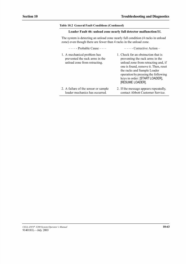
8/21/2019 Equ22-14 CellDyn3200 Op Man
http://slidepdf.com/reader/full/equ22-14-celldyn3200-op-man 505/690
CELL-DYN ® 3200 System Operator’s Manual 10-63
9140181L—July 2003
Section 10 Troubleshooting and Diagnostics
Loader Fault 46: unload zone nearly full detector malfunction/BL
The system is detecting an unload zone nearly full condition (4 racks in unload
zone) even though there are fewer than 4 racks in the unload zone.
– – – - Probable Cause – – – – – – - Corrective Action –
1. A mechanical problem has
prevented the rack arms in the
unload zone from retracting.
1. Check for an obstruction that is
preventing the rack arms in the
unload zone from retracting and, if
one is found, remove it. Then, reset
the racks and Sample Loader
operation by pressing the following
keys in order: [START LOADER],
[RESUME LOADER].
2. A failure of the sensor or sample
loader mechanics has occurred.
2. If the message appears repeatedly,
contact Abbott Customer Service.
Table 10.2 General Fault Conditions (Continued)

8/21/2019 Equ22-14 CellDyn3200 Op Man
http://slidepdf.com/reader/full/equ22-14-celldyn3200-op-man 506/690
10-64 CELL-DYN ® 3200 System Operator’s Manual
9140181M—June 2004
Troubleshooting and Diagnostics
Tables for Instrument Conditions and Messages Section 10
Loader Fault 47: tube stuck in position 3/BL
The sensor for tube position 3 in the mixing zone is sensing the presence of a tube
when the tube should be lifted clear of the rack by the Mix Head
– – – - Probable Cause – – – – – – - Corrective Action –
1. The Mix Head has failed to lift the
tube in position 3.
a. The tube in position 3 has liquid
on it.
1. The Mix Head has failed to lift the
tube in position 3.
a. Dry the tube in position 3. Then,
reset the racks and reset the
Sample Loader by pressing the
following keys in order:
[CLEAR FAULT],
[START LOADER],
[RESET LOADER].
b. The tube in position 3 either has a
loose bar code label or too many
bar code labels.
b. If the bar code label is loose,
secure it in place. If multiple bar
code labels are on the tube,
remove them and carefully apply
a single bar code label. Then,
reset the racks, and reset the
Sample Loader.
NOTE: For information
concerning proper
application of bar codes,
refer to Section 13:
Sample Loader ;Subsection: Bar Code
Label Placement .
c. The Mix Head Tube Grippers are
dirty.
c. Remove the Loader Cover.
Using a lint-free pad moistened
with a 0.5% sodium hypochlorite
solution, clean the Mix Head
Tube Gripper. (See the formula
for mixing this solution under
Section 9: Service and
Maintenance; Subsection:
Decontamination Procedures.)Repeat with deionized water.
Dry the Mix Head thoroughly.
Then, reinstall the Loader Cover,
reset the racks, and reset the
Sample Loader.
Table 10.2 General Fault Conditions (Continued)

8/21/2019 Equ22-14 CellDyn3200 Op Man
http://slidepdf.com/reader/full/equ22-14-celldyn3200-op-man 507/690
CELL-DYN ® 3200 System Operator’s Manual 10-65
9140181M—June 2004
Section 10 Troubleshooting and Diagnostics
Loader Fault 47: tube stuck in position 3/BL (Continued)
2. The tube position sensor is dirty. 2. Remove the Loader Cover. Using a
lint-free pad moistened with lens
cleaner or deionized water, cleanthe tube sensors (the tube position 3
sensor is on the right). Dry the
sensors thoroughly. Then, reinstall
the Loader Cover, reset the racks,
and reset the Sample Loader.
NOTE: For the location of the tube
sensors, refer to the figure
in Section 13: Sample
Loader ; Subsection:
Processing Stations.
3. A failure of the sensor or relatedelectronics has occurred.
3. If the message appears repeatedly,contact Abbott Customer Service.
Table 10.2 General Fault Conditions (Continued)

8/21/2019 Equ22-14 CellDyn3200 Op Man
http://slidepdf.com/reader/full/equ22-14-celldyn3200-op-man 508/690
10-66 CELL-DYN ® 3200 System Operator’s Manual
9140181M—June 2004
Troubleshooting and Diagnostics
Tables for Instrument Conditions and Messages Section 10
Loader Fault 48: tube stuck in position 4/BL
The sensor for tube position 4 in the mix zone is sensing the presence of a tube
when the tube should be lifted clear of the rack.
– – – - Probable Cause – – – – – – - Corrective Action –
1. The Mix Head has failed to lift the
tube in position 4.
a. The tube in position 4 has liquid
on it.
1. The Mix Head has failed to lift the
tube in position 4.
a. Dry the tube in position 4. Then,
reset the racks and reset the
Sample Loader by pressing the
following keys in order:
[CLEAR FAULT],
[START LOADER],
[RESET LOADER].
b. The tube in position 4 either has a
loose bar code label or too many
bar code labels.
b. If the bar code label is loose,
secure it in place. If multiple bar
code labels are on the tube,
remove them and carefully apply
a single bar code label. Then,
reset the racks, and reset the
Sample Loader.
NOTE: For information
concerning proper
application of bar codes,
refer to Section 13:
Sample Loader ;Subsection: Bar Code
Label Placement .
c. the Mix Head Tube Grippers are
dirty.
c. Remove the Loader Cover.
Using a lint-free pad moistened
with a 0.5% sodium hypochlorite
solution, clean the Mix Head
Tube Gripper. (See the formula
for mixing this solution under
Section 9: Service and
Maintenance; Subsection:
Decontamination Procedures.)Repeat with deionized water.
Dry the Mix Head thoroughly.
Then, reinstall the Loader Cover,
reset the racks, and reset the
Sample Loader.
Table 10.2 General Fault Conditions (Continued)
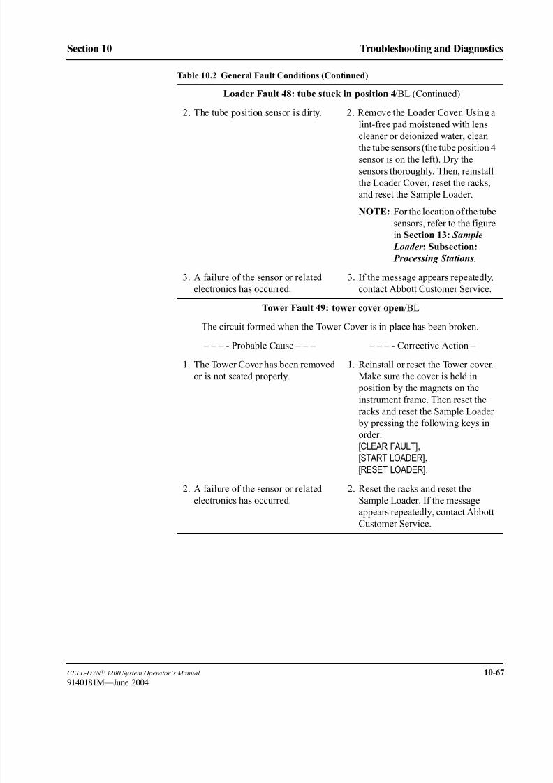
8/21/2019 Equ22-14 CellDyn3200 Op Man
http://slidepdf.com/reader/full/equ22-14-celldyn3200-op-man 509/690
CELL-DYN ® 3200 System Operator’s Manual 10-67
9140181M—June 2004
Section 10 Troubleshooting and Diagnostics
Loader Fault 48: tube stuck in position 4/BL (Continued)
2. The tube position sensor is dirty. 2. Remove the Loader Cover. Using a
lint-free pad moistened with lens
cleaner or deionized water, cleanthe tube sensors (the tube position 4
sensor is on the left). Dry the
sensors thoroughly. Then, reinstall
the Loader Cover, reset the racks,
and reset the Sample Loader.
NOTE: For the location of the tube
sensors, refer to the figure
in Section 13: Sample
Loader ; Subsection:
Processing Stations.
3. A failure of the sensor or relatedelectronics has occurred.
3. If the message appears repeatedly,contact Abbott Customer Service.
Tower Fault 49: tower cover open/BL
The circuit formed when the Tower Cover is in place has been broken.
– – – - Probable Cause – – – – – – - Corrective Action –
1. The Tower Cover has been removed
or is not seated properly.
1. Reinstall or reset the Tower cover.
Make sure the cover is held in
position by the magnets on the
instrument frame. Then reset the
racks and reset the Sample Loader by pressing the following keys in
order:
[CLEAR FAULT],
[START LOADER],
[RESET LOADER].
2. A failure of the sensor or related
electronics has occurred.
2. Reset the racks and reset the
Sample Loader. If the message
appears repeatedly, contact Abbott
Customer Service.
Table 10.2 General Fault Conditions (Continued)

8/21/2019 Equ22-14 CellDyn3200 Op Man
http://slidepdf.com/reader/full/equ22-14-celldyn3200-op-man 510/690
10-68 CELL-DYN ® 3200 System Operator’s Manual
9140181L—July 2003
Troubleshooting and Diagnostics
Tables for Instrument Conditions and Messages Section 10
Tower Fault 50: probe stuck at home position/BL
NOTE: The home position for the probe is the uppermost position.
The sensor indicates that the probe is in the home position when the System does
not expect the probe to be homed.
– – – - Probable Cause – – – – – – - Corrective Action –
1. A mechanical problem has
prevented the probe from leaving
the home position on the Aspiration
Tower.
1. Remove the Loader Cover. Check
for an obstruction on the Aspiration
Tower that is preventing the probe
from leaving the home position
and, if one is found, remove it.
Then, reinstall the Loader Cover,
reset the racks, and reset the Sample
Loader by pressing the following
keys in order:[CLEAR FAULT], [START LOADER],
[RESET LOADER].
2. A failure of the sensor or related
electronics has occurred.
2. Reset the racks and reset the
Sample Loader.
3. The tower, motor, or related
electronics is defective.
3. If the message appears repeatedly,
contact Abbott Customer Service.
Tower Fault 100: probe unable to reach home position/BL
NOTE: The home position for the probe is the uppermost position.
The sensor system indicates that the probe is not in the home position when thesystem expects the probe to be homed.
– – – - Probable Cause – – – – – – - Corrective Action –
1. A mechanical problem has
prevented the probe from reaching
the home position on the Aspiration
Tower.
1. Remove the Loader Cover. Check
for an obstruction on the Aspiration
tower that is preventing the probe
from reaching the home position
and, if one is found, remove it.
Then, reinstall the Loader Cover,
reset the racks, and reset the Sample
Loader by pressing the followingkeys in order:
[CLEAR FAULT], [START LOADER],
[RESET LOADER].
2. A failure of the sensor or related
electronics has occurred.
2. Reset the racks and reset the
Sample Loader.
3. The tower, tower motor, or related
electronics is defective.
3. If the message appears repeatedly,
contact Abbott Customer Service.
Table 10.2 General Fault Conditions (Continued)

8/21/2019 Equ22-14 CellDyn3200 Op Man
http://slidepdf.com/reader/full/equ22-14-celldyn3200-op-man 511/690
CELL-DYN ® 3200 System Operator’s Manual 10-69
9140181M—June 2004
Section 10 Troubleshooting and Diagnostics
Tower Fault 141: invalid tube height/BL
The tube height sensor system indicates that the tube at the Aspiration Station
exceeds height specification.
– – – - Probable Cause – – – – – – - Corrective Action –
1. The instrument cannot
accommodate the height of the tube.
1. To run the sample in the Sample
Loader, pour the sample into a tube
without anti-coagulant that meets
height specification. Then reset the
racks and reset the Sample Loader
by pressing the following keys in
order:
[CLEAR FAULT],
[START LOADER],
[RESET LOADER].
NOTE: For tube height
specifications, refer to
Section 13: Sample
Loader ; Subsection:
Physical and
Performance
Specifications.
2. Failure of the sensor or related
electronics has occurred.
2. Reset the racks and reset the
Sample Loader.
3. The tube height sensor or sensor flag
on the Tower is not moving into
position properly.
a. The Guide Shafts are dirty.
3. The tube height sensor or sensor
flag on the Tower is not moving
into position properly.
a. Remove the Loader Cover.
Using a lint-free pad moistened
with isopropyl alcohol, clean the
Guide Shafts. Then, reinstall the
Loader cover, reset the racks,
and reset the Sample Loader.
NOTE: The Guide Shafts are the
three vertical bars on the
tower.
Table 10.2 General Fault Conditions (Continued)

8/21/2019 Equ22-14 CellDyn3200 Op Man
http://slidepdf.com/reader/full/equ22-14-celldyn3200-op-man 512/690
10-70 CELL-DYN ® 3200 System Operator’s Manual
9140181L—July 2003
Troubleshooting and Diagnostics
Tables for Instrument Conditions and Messages Section 10
Tower Fault 141: invalid tube height/BL (Continued)
b. A mechanical problem is
preventing the tube spinning
assembly with tube height sensorflag from moving up and down
properly.
b. Remove the Loader Cover.
Check for an obstruction that is
preventing the tube spinningassembly with tube height sensor
flag from moving up and down
properly and, if one is found,
remove it. Then, reinstall the
Loader Cover, reset the racks,
and reset the Sample Loader.
c. The tube height sensor flag is
bent or the tower sensors, motor,
or related electronics are
defective.
c. Contact Abbott Customer
Service.
Tower Fault 142: no tube present/BL
The tube height sensor did not sense a tube when one was expected.
– – – - Probable Cause – – – – – – - Corrective Action –
1. The tube being processed is too
short.
1. To run the sample in the Sample
Loader, pour the sample into a tube
without anti-coagulant that meets
height specifications. Then, reset
the racks and rest the Sample
Loader by pressing the following
keys in order:
[CLEAR FAULT],
[START LOADER],
[RESET LOADER].
NOTE: For tube height
specifications, refer to
Section 13: Sample
Loader ; Subsection:
Physical and
Performance
Specifications.
2. A failure of the sensor or relatedelectronics has occurred.
2. Reset the racks and reset theSample Loader.
Table 10.2 General Fault Conditions (Continued)

8/21/2019 Equ22-14 CellDyn3200 Op Man
http://slidepdf.com/reader/full/equ22-14-celldyn3200-op-man 513/690
CELL-DYN ® 3200 System Operator’s Manual 10-71
9140181M—June 2004
Section 10 Troubleshooting and Diagnostics
Loader Warning 144: excessive cycling/BL
NOTE: The Sample Loader halts.
Twenty rack advances have occurred without a tube being sensed in the mix zone
or twenty-five rack advances have occurred after the last tube was processed.
– – – - Probable Cause – – – – – – - Corrective Action –
1. The System is functioning as
intended.
1. No corrective action is necessary.
When you wish to run additional
samples in the Sample Loader, load
tubes in racks and press the keys in
the following order:
[CLEAR FAULT],
[START LOADER],
[RESUME LOADER].
2. The rack advance mechanism is not
making contact with the racks.
2. Check for an obstruction that is
preventing the rack arms from
extending and holding the racks
against the loader wall so the racks
can engage with the rack advance
mechanism. If an obstruction is
found, remove it. Then, reset the
racks and reset the Sample Loader
by pressing the following keys in
order:
[CLEAR FAULT],
[START LOADER],[RESET LOADER].
3. Both tube sensors are dirty. 3. Remove the Loader Cover. Using a
lint-free pad moistened with lens
cleaner or deionized water, clean
the tube sensors. Then, reinstall the
Loader Cover, reset the racks, and
reset the Sample Loader.
NOTE: For the location of the tube
sensor, refer to the figure
in Section 13: Sample
Loader ; Subsection: Processing Stations.
4. A failure of the sensor or related
electronics, or loader mechanisms
has occurred.
4. If the message appears repeatedly,
contact Abbott Customer Service.
Table 10.2 General Fault Conditions (Continued)

8/21/2019 Equ22-14 CellDyn3200 Op Man
http://slidepdf.com/reader/full/equ22-14-celldyn3200-op-man 514/690
10-72 CELL-DYN ® 3200 System Operator’s Manual
9140181L—July 2003
Troubleshooting and Diagnostics
Tables for Instrument Conditions and Messages Section 10
Loader Fault 147: unload area hardware malfunction/BL
The sensor system is indicating that the unload area is full (contains 5 racks), but
is not indicating that it is also nearly full (contains 4 racks).
– – – - Probable Cause – – – – – – - Corrective Action –
1. One or more racks did not move
properly in the unload area.
1. Check for an obstruction that is
preventing rack movement in the
unload area and, if one is found,
remove it. Then, reset the racks and
reset the Sample Loader by
pressing the following keys in
order:
[CLEAR FAULT],
[START LOADER],
[RESET LOADER].
2. A failure of the sensor system or
related electronics has occurred.
2. Reset the racks and reset the
Sample Loader. If the message
appears repeatedly, contact Abbott
Customer Service.
Table 10.2 General Fault Conditions (Continued)
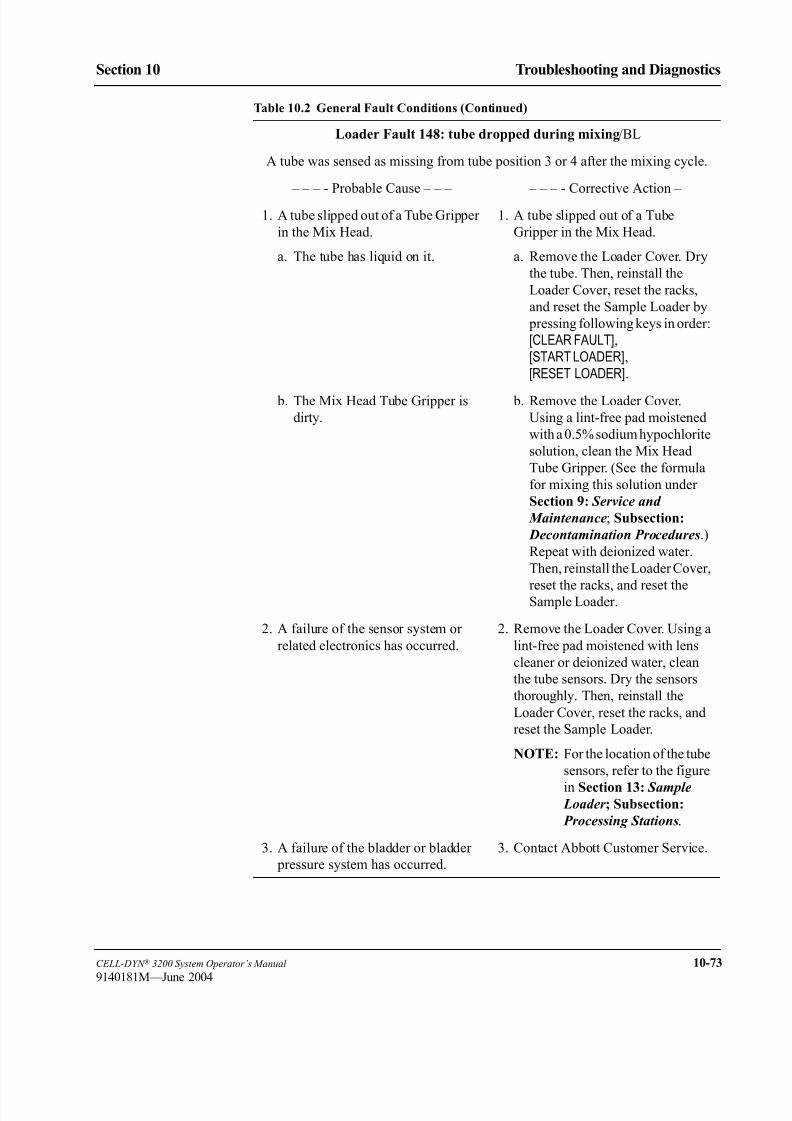
8/21/2019 Equ22-14 CellDyn3200 Op Man
http://slidepdf.com/reader/full/equ22-14-celldyn3200-op-man 515/690
CELL-DYN ® 3200 System Operator’s Manual 10-73
9140181M—June 2004
Section 10 Troubleshooting and Diagnostics
Loader Fault 148: tube dropped during mixing/BL
A tube was sensed as missing from tube position 3 or 4 after the mixing cycle.
– – – - Probable Cause – – – – – – - Corrective Action –
1. A tube slipped out of a Tube Gripper
in the Mix Head.
a. The tube has liquid on it.
1. A tube slipped out of a Tube
Gripper in the Mix Head.
a. Remove the Loader Cover. Dry
the tube. Then, reinstall the
Loader Cover, reset the racks,
and reset the Sample Loader by
pressing following keys in order:
[CLEAR FAULT],
[START LOADER],
[RESET LOADER].
b. The Mix Head Tube Gripper is
dirty.
b. Remove the Loader Cover.
Using a lint-free pad moistened
with a 0.5% sodium hypochlorite
solution, clean the Mix Head
Tube Gripper. (See the formula
for mixing this solution under
Section 9: Service and
Maintenance; Subsection:
Decontamination Procedures.)
Repeat with deionized water.
Then, reinstall the Loader Cover,
reset the racks, and reset theSample Loader.
2. A failure of the sensor system or
related electronics has occurred.
2. Remove the Loader Cover. Using a
lint-free pad moistened with lens
cleaner or deionized water, clean
the tube sensors. Dry the sensors
thoroughly. Then, reinstall the
Loader Cover, reset the racks, and
reset the Sample Loader.
NOTE: For the location of the tube
sensors, refer to the figure
in Section 13: Sample Loader ; Subsection:
Processing Stations.
3. A failure of the bladder or bladder
pressure system has occurred.
3. Contact Abbott Customer Service.
Table 10.2 General Fault Conditions (Continued)
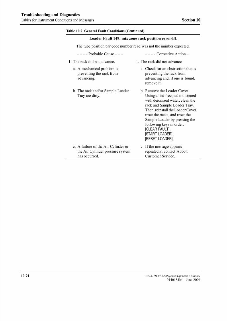
8/21/2019 Equ22-14 CellDyn3200 Op Man
http://slidepdf.com/reader/full/equ22-14-celldyn3200-op-man 516/690
10-74 CELL-DYN ® 3200 System Operator’s Manual
9140181M—June 2004
Troubleshooting and Diagnostics
Tables for Instrument Conditions and Messages Section 10
Loader Fault 149: mix zone rack position error/BL
The tube position bar code number read was not the number expected.
– – – - Probable Cause – – – – – – - Corrective Action –
1. The rack did not advance.
a. A mechanical problem is
preventing the rack from
advancing.
1. The rack did not advance.
a. Check for an obstruction that is
preventing the rack from
advancing and, if one is found,
remove it.
b. The rack and/or Sample Loader
Tray are dirty.
b. Remove the Loader Cover.
Using a lint-free pad moistened
with deionized water, clean the
rack and Sample Loader Tray.
Then, reinstall the Loader Cover,
reset the racks, and reset the
Sample Loader by pressing the
following keys in order:
[CLEAR FAULT],
[START LOADER],
[RESET LOADER].
c. A failure of the Air Cylinder or
the Air Cylinder pressure system
has occurred.
c. If the message appears
repeatedly, contact Abbott
Customer Service.
Table 10.2 General Fault Conditions (Continued)

8/21/2019 Equ22-14 CellDyn3200 Op Man
http://slidepdf.com/reader/full/equ22-14-celldyn3200-op-man 517/690
CELL-DYN ® 3200 System Operator’s Manual 10-75
9140181M—June 2004
Section 10 Troubleshooting and Diagnostics
Loader Fault 150: unexpected tube in position 4 after rack advance/BL
A tube was not sensed in tube position 3 before a rack advance, but a tube was
sensed in tube position 4 after a rack advance.
– – – - Probable Cause – – – – – – - Corrective Action –
1. The rack did not advance.
a. A mechanical problem is
preventing the rack from
advancing.
1. The rack did not advance.
a. Check for an obstruction that is
preventing the rack from
advancing and, if one is found,
remove it.
b. The rack and/or Sample Loader
Tray are dirty.
b. Remove the Loader Cover.
Using a lint-free pad moistened
with deionized water, clean the
rack and Sample Loader Tray.
Then, reinstall the Loader Cover,
reset the racks, and reset the
Sample Loader by pressing the
following keys in order:
[CLEAR FAULT],
[START LOADER],
[RESET LOADER].
c. A failure of the Air Cylinder or
the Air Cylinder pressure system
has occurred.
c. If the message appears
repeatedly, contact Abbott
Customer Service.
2. Tube sensor in position 3 is dirty. 2. Remove the Loader Cover. Using alint-free pad moistened with lens
cleaner or deionized water, clean
the tube sensors. Dry the sensors
thoroughly. Then reinstall the
Loader Cover, reset the racks, and
reset the Sample Loader.
3. A failure of the sensor system or
related electronics has occurred.
3. If the message appears repeatedly,
contact Abbott Customer Service.
Table 10.2 General Fault Conditions (Continued)

8/21/2019 Equ22-14 CellDyn3200 Op Man
http://slidepdf.com/reader/full/equ22-14-celldyn3200-op-man 518/690
10-76 CELL-DYN ® 3200 System Operator’s Manual
9140181M—June 2004
Troubleshooting and Diagnostics
Tables for Instrument Conditions and Messages Section 10
Loader Fault 151: tube lost moving from position 3 to 4/BL
A tube was sensed in tube position 3 before the rack advance, but a tube was not
sensed in tube position 4 after the rack advance.
– – – - Probable Cause – – – – – – - Corrective Action –
1. The rack did not advance.
a. A mechanical problem is
preventing the rack from
advancing.
1. The rack did not advance.
a. Check for an obstruction that is
preventing the rack from
advancing and, if one is found,
remove it.
b. The rack and/or Sample Loader
Tray are dirty.
b. Remove the Loader Cover.
Using a lint-free pad moistened
with lense cleaner or deionized
water, clean the rack and Sample
Loader Tray. Then, reinstall the
Loader Cover, reset the racks,
and reset the Sample Loader by
pressing the following keys in
order:
[CLEAR FAULT],
[START LOADER],
[RESET LOADER].
c. A failure of the Air Cylinder or
the Air Cylinder pressure system
has occurred.
c. If the message appears
repeatedly, contact Abbott
Customer Service
2. Tube sensor in position 4 is dirty. 2. Remove the Loader Cover. Using a
lint-free pad moistened with lens
cleaner or deionized water, clean
the tube sensors. Dry the sensors
thoroughly. Then reinstall the
Loader Cover, reset the racks, and
reset the Sample Loader.
3. A failure of the sensor system or
related electronics has occurred.
3. If the message appears repeatedly,
contact Abbott Customer Service.
Table 10.2 General Fault Conditions (Continued)

8/21/2019 Equ22-14 CellDyn3200 Op Man
http://slidepdf.com/reader/full/equ22-14-celldyn3200-op-man 519/690
CELL-DYN ® 3200 System Operator’s Manual 10-77
9140181M—June 2004
Section 10 Troubleshooting and Diagnostics
Loader Fault 152: mix zone must be cleared for reset/BL
The sensor system indicates that a tube is present in tube position 4 immediately
after the Sample Loader was reset, but a rack has not yet been pushed into the
mix zone.
– – – - Probable Cause – – – – – – - Corrective Action –
1. A rack remains in the mix zone
when the Sample Loader is reset.
1. Remove the rack from the mix
zone. Then, reset the racks and reset
the Sample Loader by pressing the
following keys in order:
[CLEAR FAULT],
[START LOADER],
[RESET LOADER].
2. There is an obstruction at tube
position 4 that is activating thesensor.
2. Remove the Loader Cover. Check
for an obstruction at tube position 4that is activating the sensor and, if
one is found, remove it. Then,
reinstall the Loader Cover, reset the
racks, and reset the Sample Loader.
3. Tube sensor in position 4 is dirty. 3. Remove the Loader Cover. Using a
lint-free pad moistened with lens
cleaner or deionized water, clean
the tube sensors. Dry the sensors
thoroughly. Then reinstall the
Loader Cover, reset the racks, and
reset the Sample Loader.
4. A failure of the sensor system or
related electronics has occurred.
4. If the message appears repeatedly,
contact Abbott Customer Service.
Table 10.2 General Fault Conditions (Continued)

8/21/2019 Equ22-14 CellDyn3200 Op Man
http://slidepdf.com/reader/full/equ22-14-celldyn3200-op-man 520/690
10-78 CELL-DYN ® 3200 System Operator’s Manual
9140181M—June 2004
Troubleshooting and Diagnostics
Tables for Instrument Conditions and Messages Section 10
Loader Fault 153: rack bar code read failure/BL
The rack bar code label (the first label on the rack) could not be read. This label
has a two-digit rack number.
– – – - Probable Cause – – – – – – - Corrective Action –
1. The window on the Bar Code
Reader is dirty.
1. Remove the Loader Cover. Using a
lint-free pad moistened with
isopropyl alcohol, lens cleaner or
deionized water, clean the window
on the Bar Code Reader. Dry the
window on the Bar Code Reader
thoroughly. Then, reinstall the
Loader Cover, reset the racks, and
reset the Sample Loader by
pressing the following keys in
order:
[CLEAR FAULT],
[START LOADER],
[RESET LOADER].
NOTE: For the location of the Bar
Code Reader, refer to
Section 13: Sample
Loader ; Subsection:
Sample Loader
Description.
2. The first rack bar code label ismissing, scuffed, or dirty.
2. Clean or replace the rack bar codelabel. Then, reset the racks and reset
the Sample Loader.
3. The rack from the mix zone was not
removed and reset before the [RESET LOADER] key was
pressed.
3. Reset the racks, then reset the
Sample Loader by pressing the
following keys in order:
[CLEAR FAULT],
[START LOADER],[RESET LOADER].
If the message appears repeatedly,
contact Abbott Customer Service.
Table 10.2 General Fault Conditions (Continued)

8/21/2019 Equ22-14 CellDyn3200 Op Man
http://slidepdf.com/reader/full/equ22-14-celldyn3200-op-man 521/690
CELL-DYN ® 3200 System Operator’s Manual 10-79
9140181M—June 2004
Section 10 Troubleshooting and Diagnostics
Loader Fault 154: tube position bar code read failure/BL
A tube position bar code label (the second through tenth labels on the rack) could
not be read.
– – – - Probable Cause – – – – – – - Corrective Action –
1. The window on the Bar Code
Reader is dirty.
1. Remove the Loader Cover. Using a
lint-free pad moistened with
isopropyl alcohol, lens cleaner or
deionized water, clean the window
on the Bar Code Reader. Dry the
window on the Bar Code Reader
thoroughly. Then, reinstall the
Loader Cover, reset the racks, and
reset the Sample Loader by
pressing the following keys in
order:
[CLEAR FAULT],
[START LOADER],
[RESET LOADER].
NOTE: For the location of the Bar
Code Reader, refer to
Section 13: Sample
Loader ; Subsection:
Sample Loader
Description.
2. The tube position bar code label isscuffed or dirty.
2. Clean or replace the tube position bar code label. Then, reset the racks
and reset the Sample Loader.
If the message appears repeatedly,
contact Abbott Customer Service.
Table 10.2 General Fault Conditions (Continued)

8/21/2019 Equ22-14 CellDyn3200 Op Man
http://slidepdf.com/reader/full/equ22-14-celldyn3200-op-man 522/690
10-80 CELL-DYN ® 3200 System Operator’s Manual
9140181M—June 2004
Troubleshooting and Diagnostics
Tables for Instrument Conditions and Messages Section 10
Loader Fault 156: bar code reader failure/BL
The tube sensors have sensed a tube, but the System was unsuccessful in reading
both the rack and tube position bar code labels.
– – – - Probable Cause – – – – – – - Corrective Action –
1. The window on the bar code reader
is dirty.
1. Remove the Loader Cover. Using a
lint-free pad moistened with
isopropyl alcohol, lens cleaner or
deionized water, clean the window
on the Bar Code Reader. Dry the
window on the Bar Code Reader
thoroughly. Then, reinstall the
Loader Cover, reset the racks, and
reset the Sample Loader by
pressing the following keys in
order:
[CLEAR FAULT],
[START LOADER],
[RESET LOADER].
2. The rack and tube position bar code
labels are not present or are
unreadable.
2. Replace the rack and tube position
bar code labels with new labels.
Then, reset the racks and reset the
Sample Loader by pressing the
following keys in order:
[CLEAR FAULT],
[START LOADER],
[RESET LOADER].
3. The Bar Code Reader cable has been
disconnected, or the Bar code
Reader or related electronics has
failed.
3. Reset the racks and reset the
Sample Loader. If the message
appears repeatedly, contact Abbott
Customer Service.
Table 10.2 General Fault Conditions (Continued)
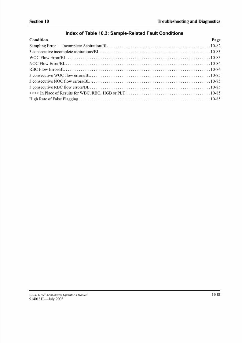
8/21/2019 Equ22-14 CellDyn3200 Op Man
http://slidepdf.com/reader/full/equ22-14-celldyn3200-op-man 523/690
CELL-DYN ® 3200 System Operator’s Manual 10-81
9140181L—July 2003
Section 10 Troubleshooting and Diagnostics
Index of Table 10.3: Sample-Related Fault Conditions
Condition Page
Sampling Error — Incomplete Aspiration/BL . . . . . . . . . . . . . . . . . . . . . . . . . . . . . . . . . . . . . . . . . . . . . . . 10-82
3 consecutive incomplete aspirations/BL . . . . . . . . . . . . . . . . . . . . . . . . . . . . . . . . . . . . . . . . . . . . . . . . . . . 10-83
WOC Flow Error/BL . . . . . . . . . . . . . . . . . . . . . . . . . . . . . . . . . . . . . . . . . . . . . . . . . . . . . . . . . . . . . . . . . . 10-83
NOC Flow Error/BL. . . . . . . . . . . . . . . . . . . . . . . . . . . . . . . . . . . . . . . . . . . . . . . . . . . . . . . . . . . . . . . . . . . 10-84
RBC Flow Error/BL . . . . . . . . . . . . . . . . . . . . . . . . . . . . . . . . . . . . . . . . . . . . . . . . . . . . . . . . . . . . . . . . . . . 10-84
3 consecutive WOC flow errors/BL . . . . . . . . . . . . . . . . . . . . . . . . . . . . . . . . . . . . . . . . . . . . . . . . . . . . . . . 10-85
3 consecutive NOC flow errors/BL . . . . . . . . . . . . . . . . . . . . . . . . . . . . . . . . . . . . . . . . . . . . . . . . . . . . . . . 10-85
3 consecutive RBC flow errors/BL. . . . . . . . . . . . . . . . . . . . . . . . . . . . . . . . . . . . . . . . . . . . . . . . . . . . . . . . 10-85
>>>> In Place of Results for WBC, RBC, HGB or PLT . . . . . . . . . . . . . . . . . . . . . . . . . . . . . . . . . . . . . . . 10-85
High Rate of False Flagging . . . . . . . . . . . . . . . . . . . . . . . . . . . . . . . . . . . . . . . . . . . . . . . . . . . . . . . . . . . . . 10-85

8/21/2019 Equ22-14 CellDyn3200 Op Man
http://slidepdf.com/reader/full/equ22-14-celldyn3200-op-man 524/690
10-82 CELL-DYN ® 3200 System Operator’s Manual
9140181L—July 2003
Troubleshooting and Diagnostics
Tables for Instrument Conditions and Messages Section 10
Table 10.3 Sample-Related Fault Conditions
Each message is followed by one of the abbreviations shown below indicating
where that message appears on the screen:
BL — Bulletin Line
SB — Status Box
Information for each message is listed in order from the most likely cause of the
message to the least likely cause of the message. Therefore, always troubleshoot
a problem in this order.
Sampling Error — Incomplete Aspiration/BL
SAMPLING ERR is displayed on the RUN screen (and SAMPLING ERR is
printed) to the right of the MCHC result.
“SAMPLING ERR” is printed on all reports.
Results may look like background counts.
– – – - Probable Cause – – – – – – – - Corrective Action – – –
1. The blood sensor system did not
detect a sufficient amount of sample
at the expected time following
aspiration.
1. Check the sample tube to be sure it
contains a sufficient quantity of
blood. Verify that the sample
contains no clots.
2. Clean the Open Sample Probe or the
Closed Sample Needle as directed in
Section 9: Service and
Maintenance; Subsection:
Unclogging the Open Sample
Aspiration Probe or Unclogging the
Closed Sample Aspiration Needle
to remove any obstructions.
3. Clean the Shear Valve as directed in
Section 9: Service and
Maintenance; Subsection: Shear
Valve Cleaning .
4. Clean the Y valve as directed in
Section 9: Service and
Maintenance; Subsection:
Nonscheduled Maintenance Procedures.
5. Contact Abbott Customer Service.

8/21/2019 Equ22-14 CellDyn3200 Op Man
http://slidepdf.com/reader/full/equ22-14-celldyn3200-op-man 525/690
CELL-DYN ® 3200 System Operator’s Manual 10-83
9140181L—July 2003
Section 10 Troubleshooting and Diagnostics
3 consecutive incomplete aspirations/BL
– – – - Probable Cause – – – – – – – - Corrective Action – – –
1. During sample processing, three
consecutive incomplete aspiration
errors were detected and the Sample
Loader halted.
1. Correct the situation on the Analyzer
as follows: Check the aspiration
tubing for a plug or a pinch. Verify
that last three tubes contained
sufficient quantity of blood.
Clean the Closed Mode needle. (If
necessary, refer to the instructions
given in Section 9: Service and
Maintenance; Subsection:
Unclogging the Closed Sample
Aspiration Needle.
2. Press the [CLEAR FAULT] keyfollowed by [RESUME LOADER] or
[RESET LOADER] displayed on the
RUN screen. The Sample Loader
continues processing.
3. If unable to resolve this problem,
contact Abbott Customer Service.
WOC Flow Error/BL
WOC FLOW ERROR is displayed on the RUN screen to the right of the EOS results.
“WOC FLOW ER” is printed on the graphics report to the right of the NEU result.
Results for WBC and Differential are suppressed.
– – – - Probable Cause – – – – – – – - Corrective Action – – –
1. An increasing WOC count rate was
detected in the optical flow cell
during the WOC measurement.
1. Repeat the sample.
2. Optical flow cell is dirty or contains
bubbles.
2. Empty/refill flow cell in Special
Protocols.
Run AutoClean and/or Extended
AutoClean.
3. Sample Dilution Delivery Problem. 3. Check/replace tubing in Sample
Transfer Pump.
Clean Sample Injection Syringe,
check for leakage, and replace as
necessary.
4. Dil/Sheath flow (partially) obstructed. 4. Replace Diluent/Sheath Filter.
Table 10.3 Sample-Related Fault Conditions

8/21/2019 Equ22-14 CellDyn3200 Op Man
http://slidepdf.com/reader/full/equ22-14-celldyn3200-op-man 526/690
10-84 CELL-DYN ® 3200 System Operator’s Manual
9140181L—July 2003
Troubleshooting and Diagnostics
Tables for Instrument Conditions and Messages Section 10
NOC Flow Error/BL
NOC FLOW ERROR is displayed on the RUN screen under the BASO result.
“NOC FLOW ER” is printed on the graphics report to the right of the LYM result.
Results for WBC and Differential are suppressed.
– – – - Probable Cause – – – – – – – - Corrective Action – – –
1. An increasing NOC count rate was
detected in the optical flow cell
during the NOC measurement.
1. Repeat the sample.
2. Optical flow cell is dirty or contains
bubbles.
2. Empty/refill flow cell in Special
Protocols.
Run AutoClean and/or Extended
AutoClean
3. Sample Dilution Delivery Problem. 3. Check/replace tubing in Sample
Transfer Pump.
Clean Sample Injection Syringe,
check for leakage and replace as
necessary.
4. Diluent/Sheath flow (partially)
obstructed.
4. Replace Diluent/Sheath Filter.
RBC Flow Error/BL
RBC FLOW ERROR is displayed on the RUN screen to the right of the RDW result.
“RBC FLOW ER” is printed on the graphics report to the right of the RDW result.
Results for RBC, PLT, and related parameters are suppressed.
– – – - Probable Cause – – – – – – – - Corrective Action – – –
1. An increasing RBC count rate was
detected in the optical flow cell
during the RBC measurement.
1. Repeat the sample.
2. Optical flow cell is dirty or contains
bubbles.
2. Empty/refill flow cell in Special
Protocols
Run AutoClean and/or Extended
AutoClean
3. Sample Dilution Delivery Problem. 3. Check/replace tubing in Sample
Transfer Pump.
Clean Sample Injection Syringe,
check for leakage, and replace as
necessary.
4. Diluent/Sheath flow (partially)
obstructed.
4. Replace Diluent/Sheath Filter.
Table 10.3 Sample-Related Fault Conditions
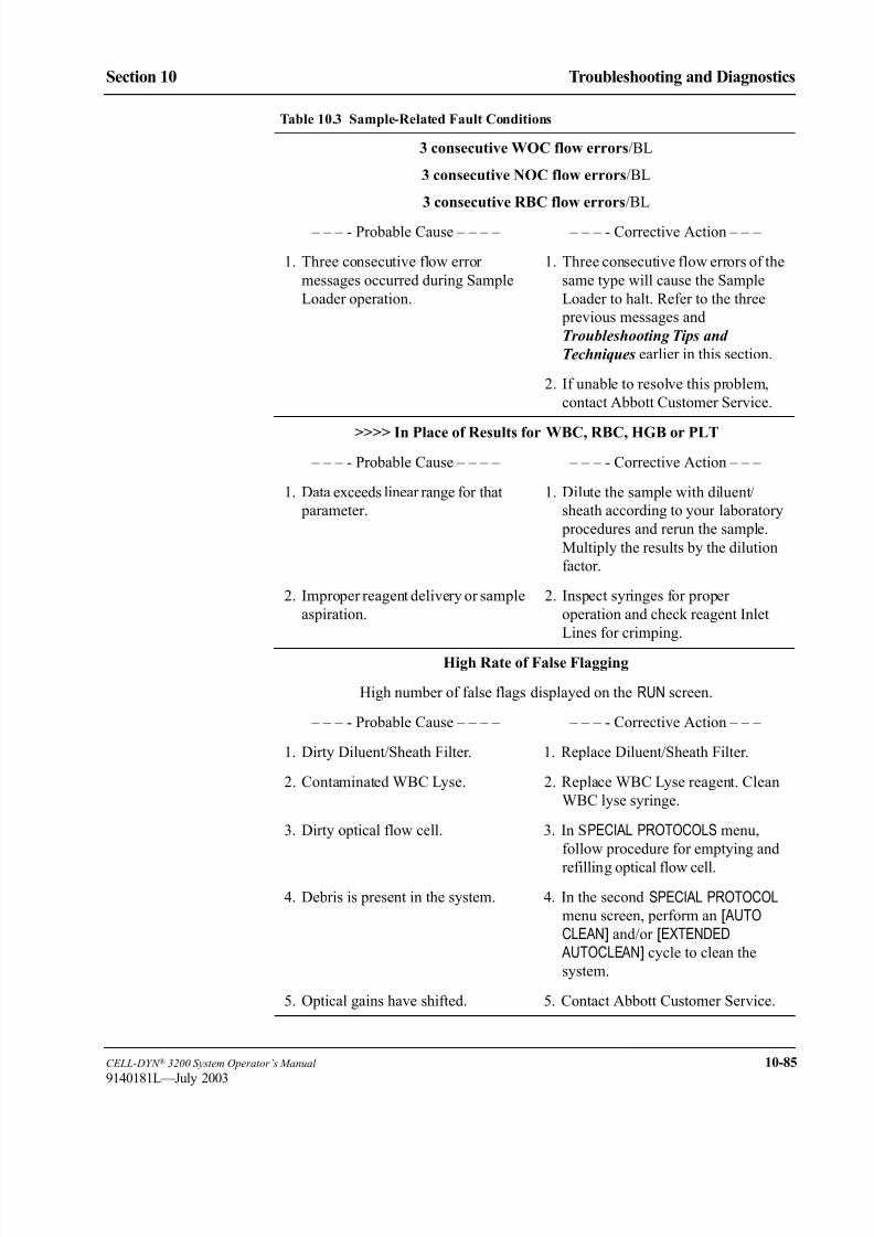
8/21/2019 Equ22-14 CellDyn3200 Op Man
http://slidepdf.com/reader/full/equ22-14-celldyn3200-op-man 527/690
CELL-DYN ® 3200 System Operator’s Manual 10-85
9140181L—July 2003
Section 10 Troubleshooting and Diagnostics
3 consecutive WOC flow errors/BL
3 consecutive NOC flow errors/BL
3 consecutive RBC flow errors/BL
– – – - Probable Cause – – – – – – – - Corrective Action – – –
1. Three consecutive flow error
messages occurred during Sample
Loader operation.
1. Three consecutive flow errors of the
same type will cause the Sample
Loader to halt. Refer to the three
previous messages and
Troubleshooting Tips and
Techniques earlier in this section.
2. If unable to resolve this problem,
contact Abbott Customer Service.
>>>> In Place of Results for WBC, RBC, HGB or PLT
– – – - Probable Cause – – – – – – – - Corrective Action – – –
1. Data exceeds linear range for that
parameter.
1. Dilute the sample with diluent/
sheath according to your laboratory
procedures and rerun the sample.
Multiply the results by the dilution
factor.
2. Improper reagent delivery or sample
aspiration.
2. Inspect syringes for proper
operation and check reagent Inlet
Lines for crimping.
High Rate of False Flagging
High number of false flags displayed on the RUN screen.
– – – - Probable Cause – – – – – – – - Corrective Action – – –
1. Dirty Diluent/Sheath Filter. 1. Replace Diluent/Sheath Filter.
2. Contaminated WBC Lyse. 2. Replace WBC Lyse reagent. Clean
WBC lyse syringe.
3. Dirty optical flow cell. 3. In SPECIAL PROTOCOLS menu,
follow procedure for emptying and
refilling optical flow cell.
4. Debris is present in the system. 4. In the second SPECIAL PROTOCOL
menu screen, perform an [ AUTOCLEAN] and/or [EXTENDED
AUTOCLEAN] cycle to clean the
system.
5. Optical gains have shifted. 5. Contact Abbott Customer Service.
Table 10.3 Sample-Related Fault Conditions

8/21/2019 Equ22-14 CellDyn3200 Op Man
http://slidepdf.com/reader/full/equ22-14-celldyn3200-op-man 528/690
10-86 CELL-DYN ® 3200 System Operator’s Manual
9140181L—July 2003
Troubleshooting and Diagnostics
Tables for Instrument Conditions and Messages Section 10
Index of Table 10.4: Non-Functional Fault Conditions
Condition Page
Analyzer will not power ON. . . . . . . . . . . . . . . . . . . . . . . . . . . . . . . . . . . . . . . . . . . . . . . . . . . . . . . . . . . . .10-87
No screen display on the Display Monitor .. . . . . . . . . . . . . . . . . . . . . . . . . . . . . . . . . . . . . . . . . . . . . . . . . . 10-88
The FAULT indicator light on the Analyzer status indicator panel is illuminated in red . . . . . . . . . . . . . . . 10-88
The message “Please check signal cable” appears on the Display Monitor . . . . . . . . . . . . . . . . . . . . . . . . .10-89
Background count is outside acceptable limits. . . . . . . . . . . . . . . . . . . . . . . . . . . . . . . . . . . . . . . . . . . . . . .10-89
The PC keyboard is not operational . . . . . . . . . . . . . . . . . . . . . . . . . . . . . . . . . . . . . . . . . . . . . . . . . . . . . . .10-90
The Sample Loader does not respond when the START LOADER, RESUME, or RESET key is pressed. . . . .10-90
The Sample Loader beeps but does not begin processing. . . . . . . . . . . . . . . . . . . . . . . . . . . . . . . . . . . . . . . 10-91
The Display Monitor membrane touch keys are not operational. . . . . . . . . . . . . . . . . . . . . . . . . . . . . . . . . .10-91

8/21/2019 Equ22-14 CellDyn3200 Op Man
http://slidepdf.com/reader/full/equ22-14-celldyn3200-op-man 529/690
CELL-DYN ® 3200 System Operator’s Manual 10-87
9140181L—July 2003
Section 10 Troubleshooting and Diagnostics
Table 10.4 Non-Functional Fault Conditions
Information for each message is listed in order from the most likely cause of the
message to the least likely cause of the message. Therefore, always troubleshoot
a problem in this order. If a problem cannot be resolved by the corrective action
indicated in this table, call for technical assistance.
Analyzer will not power ON
– – – - Probable Cause – – – – – – – - Corrective Action – – –
1. Power cord is not securely
connected to the Analyzer or is not
connected to the power outlet.
1. Ensure that the power cord is
securely connected to the Analyzer
and verify that it is connected to the
power outlet.
2. Power source is defective. 2. Turn the power switch OFF and
connect the system to a different
power source.Turn the power switch
ON.
3. Analyzer fuse has failed or is
incorrect.
3. Analyzer fuse is located above the
power cord connector on the rear
panel. Check the fuse as directed in
the Section 9: Service and
Maintenance; Subsection: Fuse
Replacement .
4. Defective power switch or other
system malfunction.
4. Contact Abbott Customer Service.

8/21/2019 Equ22-14 CellDyn3200 Op Man
http://slidepdf.com/reader/full/equ22-14-celldyn3200-op-man 530/690
10-88 CELL-DYN ® 3200 System Operator’s Manual
9140181L—July 2003
Troubleshooting and Diagnostics
Tables for Instrument Conditions and Messages Section 10
No screen display on the Display Monitor
– – – - Probable Cause – – – – – – – - Corrective Action – – –
1. Display Monitor is not ON or is not
connected to power source.
1. Verify the Display Monitor LED is
ON. If not, check that the power
cord is securely connected to the
power outlet. Try a different power
source.
2. Display Monitor brightness control
is turned down.
2. Adjust the brightness control under
the front control panel of the Display
Monitor until the image is visible.
3. The Display Monitor interface
connector (VGA, 25 pin) is not
securely connected.
3. Locate the connector on the rear
panel of the Data Module, reseat the
cable and secure the connection
properly.
NOTE: For the location of the
VGA connector, refer to
Section 1: Use or
Function; Subsection:
Data Module
Components.
4. Defective Display Monitor or other
component.
4. Contact Abbott Customer Service.
The FAULT indicator light on the Analyzer status indicator panel is
illuminated in red
NOTE: This type of fault is usually accompanied by a message in the status box
and/or on the bulletin line.
– – – - Probable Cause – – – – – – – - Corrective Action – – –
1. The Analyzer has detected a fault
situation and has stopped operating.
1. From the first DIAGNOSTICS MENUscreen, press [FAULT REPORT]. Print
a copy of the report and perform the
indicated corrective action. When the action is completed, initialize the
Analyzer by pressing the
[INITIALIZATION] key on the secondDIAGNOSTICS MENU screen.
2. If the fault report does not indicate a
message or action, document the
situation and initialize the Analyzer
by pressing the [INITIALIZATION] key
on the second DIAGNOSTICS MENU
screen.
Table 10.4 Non-Functional Fault Conditions (Continued)

8/21/2019 Equ22-14 CellDyn3200 Op Man
http://slidepdf.com/reader/full/equ22-14-celldyn3200-op-man 531/690
CELL-DYN ® 3200 System Operator’s Manual 10-89
9140181L—July 2003
Section 10 Troubleshooting and Diagnostics
The message “Please check signal cable” appears on the Display Monitor
– – – - Probable Cause – – – – – – – - Corrective Action – – –
1. The Display Monitor interface cable
is not securely connected.
1. Locate the VGA connector (25 pin)
on the Rear Panel of the Data
Module. Reseat the cable and secure
the connection properly.
2. Defective Data Module component. 2. Contact Abbott Customer Service.
Background count is outside acceptable limits
– – – - Probable Cause – – – – – – – - Corrective Action – – –
1. Debris is present in the system. 1. In the second SPECIAL PROTOCOLSMENU screen, perform an [AUTOCLEAN] cycle to clean the system.
When the cycle is completed, run aBackground count.
2. The reagents are cold — less than
59°F (15°C).
2. Allow the reagents to warm to room
temperature and then repeat the
Background count.
3. The reagents are contaminated. 3. Replace the appropriate reagent
according to the directions given in
Troubleshooting Reagent Problems
cited earlier in this section.
4. Diluent/Sheath filter is dirty. 4. Replace Diluent/Sheath filter.
5. Syringes are the source of
contamination.
5. Clean the appropriate syringe.
6. The Shear Valve is dirty. 6. Clean the Shear Valve. Repeat the
Background count.
Table 10.4 Non-Functional Fault Conditions (Continued)

8/21/2019 Equ22-14 CellDyn3200 Op Man
http://slidepdf.com/reader/full/equ22-14-celldyn3200-op-man 532/690
10-90 CELL-DYN ® 3200 System Operator’s Manual
9140181L—July 2003
Troubleshooting and Diagnostics
Tables for Instrument Conditions and Messages Section 10
The PC keyboard is not operational
– – – - Probable Cause – – – – – – – - Corrective Action – – –
1. The computer is performing a
function that inhibits the keys.
1. No action required. Refer to the screen
for the current Status Box message.
2. There is an incomplete operator
entry.
2. Complete the operator entry or press
the Esc key on the PC keyboard.
3. A data transmission to the printer or
laboratory computer is in progress.
3. No action required. Refer to the
screen for the Status Box message.
4. Keyboard entry is not possible on
the displayed screen.
4. No action required. Refer to the screen
for the current Status Box message.
5. Computer, keyboard and/or circuitry
malfunction.
5. Power OFF the Analyzer. Then reset
the Keyboard cable on the rear panel
of the Data Module and powerAnalyzer ON.
NOTE: For the location of the
keyboard connector, refer
to Section 1: Use or
Function; Subsection:
Data Module
Components. If necessary,
contact Abbott Customer
Service.
The Sample Loader does not respond when the START LOADER,
RESUME, or RESET key is pressed
– – – - Probable Cause – – – – – – – - Corrective Action – – –
1. The internal power cord connecting
the Sample Loader to the Analyzer
is loose or disconnected.
1. Contact Abbott Customer Service.
2. Circuitry malfunction. 2. Press [FAULT REPORT] in the main
DIAGNOSTICS MENU and record any
fault listed.
3. Turn the instrument OFF and ON
again and prime the instrument.
4. If the problem persists, contact
Abbott Customer Service.
Table 10.4 Non-Functional Fault Conditions (Continued)
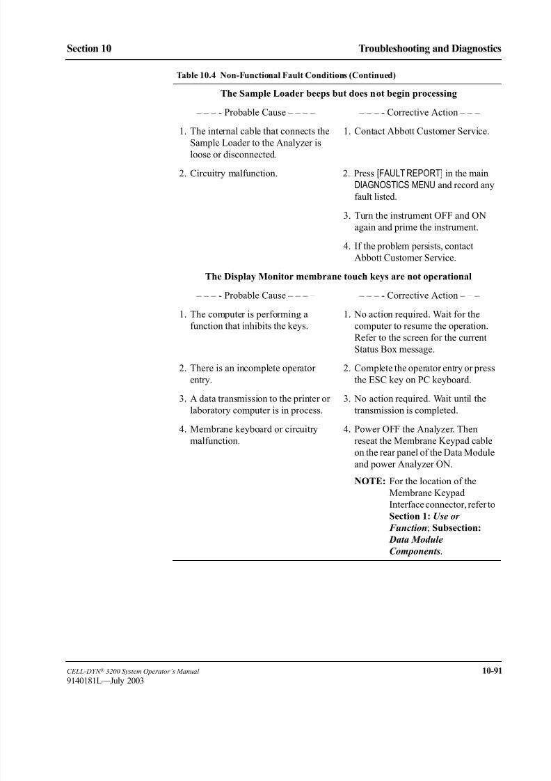
8/21/2019 Equ22-14 CellDyn3200 Op Man
http://slidepdf.com/reader/full/equ22-14-celldyn3200-op-man 533/690
CELL-DYN ® 3200 System Operator’s Manual 10-91
9140181L—July 2003
Section 10 Troubleshooting and Diagnostics
The Sample Loader beeps but does not begin processing
– – – - Probable Cause – – – – – – – - Corrective Action – – –
1. The internal cable that connects the
Sample Loader to the Analyzer is
loose or disconnected.
1. Contact Abbott Customer Service.
2. Circuitry malfunction. 2. Press [FAULT REPORT] in the main
DIAGNOSTICS MENU and record any
fault listed.
3. Turn the instrument OFF and ON
again and prime the instrument.
4. If the problem persists, contact
Abbott Customer Service.
The Display Monitor membrane touch keys are not operational
– – – - Probable Cause – – – – – – – - Corrective Action – – –
1. The computer is performing a
function that inhibits the keys.
1. No action required. Wait for the
computer to resume the operation.
Refer to the screen for the current
Status Box message.
2. There is an incomplete operator
entry.
2. Complete the operator entry or press
the ESC key on PC keyboard.
3. A data transmission to the printer or
laboratory computer is in process.
3. No action required. Wait until the
transmission is completed.
4. Membrane keyboard or circuitry
malfunction.
4. Power OFF the Analyzer. Then
reseat the Membrane Keypad cable
on the rear panel of the Data Module
and power Analyzer ON.
NOTE: For the location of the
Membrane Keypad
Interface connector, refer to
Section 1: Use or
Function; Subsection:
Data Module
Components.
Table 10.4 Non-Functional Fault Conditions (Continued)
8/21/2019 Equ22-14 CellDyn3200 Op Man
http://slidepdf.com/reader/full/equ22-14-celldyn3200-op-man 534/690
10-92 CELL-DYN ® 3200 System Operator’s Manual
9140181L—July 2003
Troubleshooting and Diagnostics
Tables for Instrument Conditions and Messages Section 10
NOTES

8/21/2019 Equ22-14 CellDyn3200 Op Man
http://slidepdf.com/reader/full/equ22-14-celldyn3200-op-man 535/690
CELL-DYN ® 3200 System Operator’s Manual 11-1
9140181H—October 2001
Section 11 Quality Control
ec on ua ty ontro
Overview
This section contains two major subsections: Quality Control Menu, and Quality
Control Guide. The Quality Control Menu describes the functions of the keys in the
QC MENU. The Quality Control Guide discusses the interpretation of QC data.
QC Options
The CELL-DYN 3200 offers several Quality Control options to monitor and
validate instrument performance. The options are:
X-B Analysis — Bull’s moving average program applied to the RBC
Indices and some WBC Differential optical
parameters. This QC option is useful for
troubleshooting and confirming that the calibration ofthe red blood cell parameters has not changed.
20 QC Files — Utilizes commercial controls (low, normal, high) or
fresh whole blood specimens to obtain statistical and
graphical analyses. The data in each file is used to
calculate the mean, standard deviation and coefficient
of variation.
Westgard® Rules — A multi-rule system applied to the data in each of the
QC Files to detect drift and imprecision and to detect
systematic or random error.
The above options may be used independently or in combination, depending on theoperator’s preference. Each option is discussed in detail in this section.
Quality Control procedures, both internal and external, allow the operator to verify
the performance of an analytical system. The use of Quality Control procedures in
evaluating both commercial controls and patient samples facilitates the
interpretation of laboratory data to ascertain acceptability of patient results.
The information in this section conforms to Abbott Laboratories’ recommended
procedures for Quality Control for all Abbott hematology instruments. It is
recommended that these guidelines be incorporated into the procedure manual for
your laboratory. In addition, refer to your laboratory's Standard Operating
Procedures and/or Quality Assurance plan for additional Quality Control
requirements.

8/21/2019 Equ22-14 CellDyn3200 Op Man
http://slidepdf.com/reader/full/equ22-14-celldyn3200-op-man 536/690
11-2 CELL-DYN ® 3200 System Operator’s Manual
9140181H—October 2001
Quality Control
Overview Section 11
NOTES

8/21/2019 Equ22-14 CellDyn3200 Op Man
http://slidepdf.com/reader/full/equ22-14-celldyn3200-op-man 537/690
CELL-DYN ® 3200 System Operator’s Manual 11-3
9140181H—October 2001
Section 11 Quality Control
Quality Control Menu
QC Menu SoftkeysThis section discusses the options available when the [QUALITY CONTROL] key is
pressed. The options used to set up the QC Files are available from the QUALITYCONTROL menu (see Figure 11.1) and the QC SET UP menu. Refer to Set Up QC
File in Section 5: Operating Instructions for an explanation of these keys as they
will not be discussed in this section.
Figure 11.1 Quality Control Menu Screen
The following soft key labels are displayed when the [QUALITY CONTROL] key on
the MAIN MENU screen is pressed:
X-B SET UP
X-B FILE
VIEW QC LOG
QC LIMITS*
SET-UP QC FILE*
CUSTOMIZE DISPLAY *
CUSTOMIZE PRINTOUT *
MAIN
* These keys are discussed in Section 5: Operating Instructions; Subsection: Set
Up Instructions.

8/21/2019 Equ22-14 CellDyn3200 Op Man
http://slidepdf.com/reader/full/equ22-14-celldyn3200-op-man 538/690
11-4 CELL-DYN ® 3200 System Operator’s Manual
9140181H—October 2001
Quality Control
Quality Control Menu Section 11
X-B Set Up
Figure 11.2 X-B Set Up Screen
The following soft key labels are displayed when the [X-B SET UP] key is pressed
(refer to Figure 11.2):
TURN X-B RBC OFF (Key label alternates between ON/OFF selections)
TURN X-B WBC OFF (Key label alternates between ON/OFF selections)PRINT
RETURN

8/21/2019 Equ22-14 CellDyn3200 Op Man
http://slidepdf.com/reader/full/equ22-14-celldyn3200-op-man 539/690
CELL-DYN ® 3200 System Operator’s Manual 11-5
9140181H—October 2001
Section 11 Quality Control
X-B File
Figure 11.3 X-B RBC Graphs Screen
The following soft key labels are displayed when the [X-B FILE] key is pressed:
X-B RBC DATA/GRAPHS (Key label alternates between selections)
X-B WBC DATA/GRAPHS (Key label alternates between selections)
PRINTRETURN
For a description of how the X-B Program works, refer to X-B Program Operation
later in this section.
Show Graphs
When the [X-B RBC GRAPHS] key or [X-B WBC GRAPHS] key is pressed, the X-B
GRAPHS DISPLAY screen for the appropriate parameter is displayed. (Refer to
Figure 11.3.)
Show Data
When the [X-B RBC DATA] key or [X-B WBC DATA] is pressed, the X-B DATA DISPLAY screen for the appropriate parameter is displayed. This screen is depicted in Figure
11.4. The screen displays the results for X-B batches 1–10 and the lower and upper
limits. The date and time that each batch was completed are also displayed. The
Page Down key on the keyboard is used to display batches 11–20. When batches
11–20 are displayed, the Page Up key on the keyboard is used to display batches
1–10.
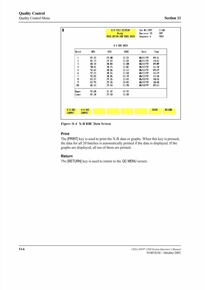
8/21/2019 Equ22-14 CellDyn3200 Op Man
http://slidepdf.com/reader/full/equ22-14-celldyn3200-op-man 540/690
11-6 CELL-DYN ® 3200 System Operator’s Manual
9140181H—October 2001
Quality Control
Quality Control Menu Section 11
Figure 11.4 X-B RBC Data Screen
The [PRINT] key is used to print the X-B data or graphs. When this key is pressed,
the data for all 20 batches is automatically printed if the data is displayed. If the
graphs are displayed, all ten of them are printed.
Return
The [RETURN] key is used to return to the QC MENU screen.

8/21/2019 Equ22-14 CellDyn3200 Op Man
http://slidepdf.com/reader/full/equ22-14-celldyn3200-op-man 541/690
CELL-DYN ® 3200 System Operator’s Manual 11-7
9140181H—October 2001
Section 11 Quality Control
View QC Log
The [VIEW QC LOG] key is used to display the QC Log indicated by the position of
the cursor.
Figure 11.5 The View QC Log Screen
Each QC Log display shows the following information (see Figure 11.5):
1. Upper Left Corner
LOT NUMBER and EXPIRATION DATE if the file was configured for this
type of control. If the file was configured for a REPLICATE ID, it is
displayed instead of the lot number and expiration date.
File name, the number of runs currently in the file and the file capacity
(e.g., 39/120 indicates that the file contains39 runs out of a possible 120).
The page number of the display and the total number of pages in the file.
2. Status Box
USE < OR > FOR MORE DATA. This message indicates that the Left and
Right Arrow keys on the keyboard should be used to display the other groupsof data.
3. Upper Right Corner
The current DATE, TIME and OPERATOR ID are displayed along with the
last SEQUENCE NUMBER that was used.
8/21/2019 Equ22-14 CellDyn3200 Op Man
http://slidepdf.com/reader/full/equ22-14-celldyn3200-op-man 542/690
11-8 CELL-DYN ® 3200 System Operator’s Manual
9140181H—October 2001
Quality Control
Quality Control Menu Section 11
4. The remainder of the screen displays the file information and the data. The
UPPER and LOWER LIMITS and TARGET MEAN entered are displayed
immediately above the parameter names. The sequence number for each
result is displayed to the left of the data. TheDATE, TIME and OPERATOR
ID when the sample was run are displayed to the right of the data.
5. The following QC Log codes are displayed in the column immediately preceding the date. These codes are the same as those used in the Data Log:
O — Sample was run in the Open mode
C — Sample was run in the Closed mode
N — Incomplete aspiration in the Open mode
I — Incomplete aspiration in the Closed mode
K — Flow Error occurred
Background and latex samples use only the O or C codes.
6. The statistics are displayed below the data as follows:
N: the Number of runs used in the calculation
FILE MEAN: the Mean value for the number of runs used in the
calculation
STD DEV: the Standard Deviation (+/-1) for the number of runs used
in the calculation
CV (%): the Coefficient of Variation in percent for the number of
runs used in the calculation
The following soft key labels are displayed on the VIEW QC LOG screen:
PURGE QC LOG
LEVEY-JENNINGS
REJECT SPECIMEN/
ACCEPT SPECIMEN (Key label alternates between selections)
DELETE SPECIMEN
MOVE SPECIMEN
WRITE QC TO DISK
PRINT QC LOG
RETURN
The function of each of these keys is discussed in this section.
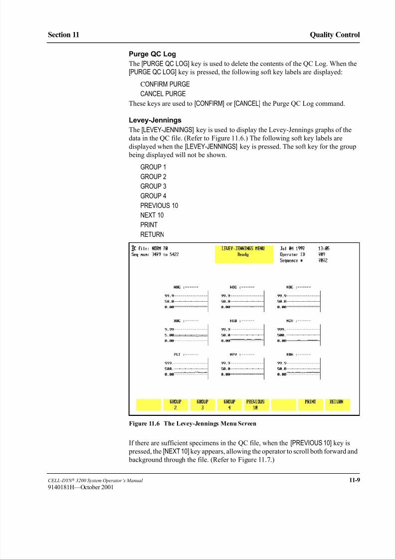
8/21/2019 Equ22-14 CellDyn3200 Op Man
http://slidepdf.com/reader/full/equ22-14-celldyn3200-op-man 543/690
CELL-DYN ® 3200 System Operator’s Manual 11-9
9140181H—October 2001
Section 11 Quality Control
Purge QC Log
The [PURGE QC LOG] key is used to delete the contents of the QC Log. When the
[PURGE QC LOG] key is pressed, the following soft key labels are displayed:
CONFIRM PURGE
CANCEL PURGE
These keys are used to [CONFIRM] or [CANCEL] the Purge QC Log command.
Levey-Jennings
The [LEVEY-JENNINGS] key is used to display the Levey-Jennings graphs of the
data in the QC file. (Refer to Figure 11.6.) The following soft key labels are
displayed when the [LEVEY-JENNINGS] key is pressed. The soft key for the group
being displayed will not be shown.
GROUP 1
GROUP 2
GROUP 3
GROUP 4PREVIOUS 10
NEXT 10
RETURN
Figure 11.6 The Levey-Jennings Menu Screen
If there are sufficient specimens in the QC file, when the [PREVIOUS 10] key is
pressed, the [NEXT 10] key appears, allowing the operator to scroll both forward and
background through the file. (Refer to Figure 11.7.)

8/21/2019 Equ22-14 CellDyn3200 Op Man
http://slidepdf.com/reader/full/equ22-14-celldyn3200-op-man 544/690
11-10 CELL-DYN ® 3200 System Operator’s Manual
9140181H—October 2001
Quality Control
Quality Control Menu Section 11
Figure 11.7 The Levey-Jennings Menu Screen Showing Next 10
Group
Each of the Group keys is used to select the graphs for a group of data that
correspond to the groups selected in the Customize QC Display option. Subsequent
groups may be selected by pressing the appropriate soft keys.
NOTE: The soft key for the group currently shown on the screen is notdisplayed.
The [PRINT] key is used to print the Levey-Jennings graphs. When the [PRINT] key
is pressed, all of the graphs are automatically printed.
Return
The [RETURN] key is used to return to the VIEW QC LOG screen.
Reject/Accept Specimen
The [REJECT SPECIMEN] key is used to exclude the results for the specimen
indicated by the cursor position. When the key is pressed, the key label changes to
[ACCEPT SPECIMEN], an “R” is displayed in the column immediately left of the
results and the statistics are recomputed excluding those results. (Refer to
Figure 11.8.) The data is still displayed and stored in the file but is excluded from
the statistical calculation.
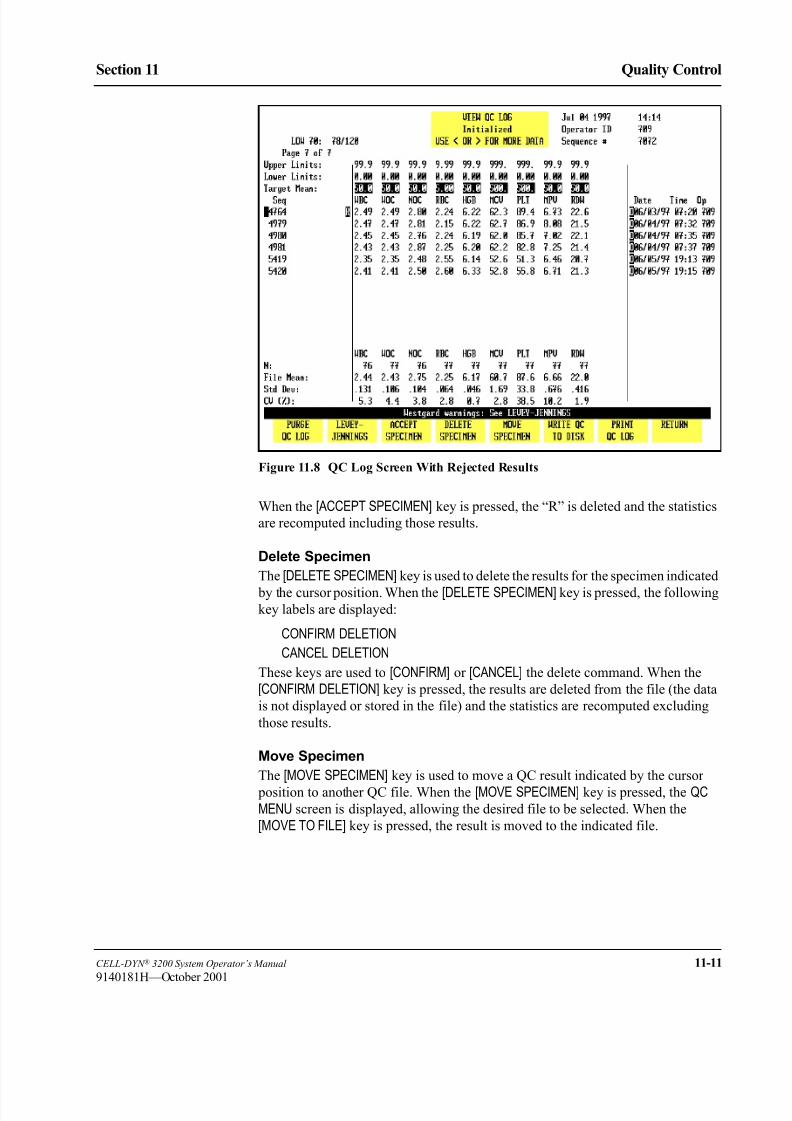
8/21/2019 Equ22-14 CellDyn3200 Op Man
http://slidepdf.com/reader/full/equ22-14-celldyn3200-op-man 545/690
CELL-DYN ® 3200 System Operator’s Manual 11-11
9140181H—October 2001
Section 11 Quality Control
Figure 11.8 QC Log Screen With Rejected Results
When the [ACCEPT SPECIMEN] key is pressed, the “R” is deleted and the statistics
are recomputed including those results.
Delete Specimen
The [DELETE SPECIMEN] key is used to delete the results for the specimen indicated
by the cursor position. When the [DELETE SPECIMEN] key is pressed, the followingkey labels are displayed:
CONFIRM DELETION
CANCEL DELETION
These keys are used to [CONFIRM] or [CANCEL] the delete command. When the
[CONFIRM DELETION] key is pressed, the results are deleted from the file (the data
is not displayed or stored in the file) and the statistics are recomputed excluding
those results.
Move Specimen
The [MOVE SPECIMEN] key is used to move a QC result indicated by the cursor
position to another QC file. When the [MOVE SPECIMEN] key is pressed, the QC
MENU screen is displayed, allowing the desired file to be selected. When the
[MOVE TO FILE] key is pressed, the result is moved to the indicated file.

8/21/2019 Equ22-14 CellDyn3200 Op Man
http://slidepdf.com/reader/full/equ22-14-celldyn3200-op-man 546/690
11-12 CELL-DYN ® 3200 System Operator’s Manual
9140181H—October 2001
Quality Control
Quality Control Menu Section 11
Move Specimen Procedure
1. From the QC MENU screen, use the Arrow keys on the keyboard to move the
cursor to the file containing the specimen to be moved.
2. Press [VIEW QC LOG].
3. Use the Arrow keys on the keyboard to position the cursor at the result that
is to be moved.
4. Press [MOVE SPECIMEN] to again display the VIEW QC LOG screen.
5. Use the Arrow keys on the keyboard to move the cursor to the file in which
the results are to be placed.
6. Press [MOVE TO FILE] to move the results to the designated file.
NOTE: The result is moved to the end of the list of data that is currently in
the file.
7. The VIEW QC LOG screen of the original file is displayed showing that the
results have been moved.
Write QC to DiskThe [WRITE QC TO DISK] key enables the download of data from a QC file(s) to a
floppy disk.
NOTE: The LAB ID SET UP must be completed prior to downloading QC data
onto a disk. (Refer to Section 5: Operating Instructions; Subsection: Set
Up Instructions.
Write QC to Disk Procedure
1. Place an appropriately-labeled blank diskette in the disk drive.
2. From the MAIN MENU screen, press [QUALITY CONTROL].
3. Place the cursor on the desired QC file and press [VIEW QC LOG].
4. Press [WRITE QC TO DISK].
5. The following message is displayed on the screen:
1.Insert the diskette into disk drive (a:).
2.Press one of the following softkeys:
a. [WRITE LOW] to transfer data into the low
control disk file.
b. [WRITE NORMAL] to transfer data into the normal
control disk file.
c. [WRITE HIGH] to transfer data into the high
control disk file.
6. Press the desired softkey. The selected softkey will label the QC file
accordingly.
7. Press [RETURN].

8/21/2019 Equ22-14 CellDyn3200 Op Man
http://slidepdf.com/reader/full/equ22-14-celldyn3200-op-man 547/690
CELL-DYN ® 3200 System Operator’s Manual 11-13
9140181H—October 2001
Section 11 Quality Control
8. Repeat steps 3-6 to write additional desired QC file levels to disk.
NOTE: The disk can store one QC file of each level. If more than one QC
file of each level is saved, the new data will overwrite the previous
data.
9. Remove the disk from the disk drive and send it to the CELL-DYN
Interlaboratory QC program for evaluation.
Print QC Log
The [PRINT QC LOG] key is used to print the entire QC log.
Return
The [RETURN] key is used to return to the QC MENU screen.
8/21/2019 Equ22-14 CellDyn3200 Op Man
http://slidepdf.com/reader/full/equ22-14-celldyn3200-op-man 548/690
11-14 CELL-DYN ® 3200 System Operator’s Manual
9140181H—October 2001
Quality Control
Quality Control Menu Section 11
NOTES
8/21/2019 Equ22-14 CellDyn3200 Op Man
http://slidepdf.com/reader/full/equ22-14-celldyn3200-op-man 549/690
CELL-DYN ® 3200 System Operator’s Manual 11-15
9140181H—October 2001
Section 11 Quality Control
Quality Control Guide
The Guide is divided into three parts. The first part discusses the handling andrunning of control material. The second part discusses the Westgard® Rules used
on the CELL-DYN 3200 System and gives guidance for their application in the
hematology laboratory. The third part discusses the X-B Analysis program in
monitoring quality control.
All QC data should be reviewed according to your laboratory’s protocol.
CELL-DYN Controls
The following controls are recommended for use on the CELL-DYN 3200 System:
CELL-DYN 22 (Tri-level), 1 box, 2.5-mL tubes x 12 (List Number 93111-01)
CELL-DYN 26 (Tri-level), 1 box, 3.0-mL tubes x 12, (List Number 01H71-01)
* CELL-DYN controls are packaged in Vacutainer ® tubes with Hemogard closure.
Use of Controls
Controls are used to determine whether an instrument is operating with accuracy
and precision. Controls normally consist of fixed blood cells with assayed ranges
for each measured parameter. Alternately, laboratories may use patient samples
that were previously found to be within set patient limits. CELL-DYN Controls
provide three control levels — low, normal, and high ranges — for each measured
parameter.
All QC data should be reviewed according to your laboratory’s protocol. Refer tothe section on Westgard® Rules for suggestions on how to use these rules in a
review protocol. Refer to the section on X-B Analysis for suggestions and
guidelines on interpreting X-B results.
Mixing and Handling
Always mix and handle commercial control materials according to the directions
given in the package insert. Because directions may vary from manufacturer to
manufacturer, pay particular attention to the following:
• Check the condition of incoming control material. Be sure the vials are at the
proper temperature and are not leaking. Check for hemolysis.
• Store controls at recommended temperatures inside the refrigerator,
preferably in a central location away from the door.
• Carefully warm and resuspend the product according to the directions given
in the package insert. Proper mixing is essential for accurate results.
• Check the shelf life and open-vial stability dating. Do not use products longer
than recommended by the manufacturer or the results may be compromised.
• Never subject any vial to excessive heat or agitation.

8/21/2019 Equ22-14 CellDyn3200 Op Man
http://slidepdf.com/reader/full/equ22-14-celldyn3200-op-man 550/690
11-16 CELL-DYN ® 3200 System Operator’s Manual
9140181H—October 2001
Quality Control
Quality Control Guide Section 11
Assay Verification
New lots of control material should be analyzed in parallel with current lots prior
to their expiration dates. Perform the following steps to accomplish the transition
to a new lot:
1. Set up a control file for the new lot.
2. Verify values for each new control lot by running each level of control in
triplicate along with either replicate QC specimens or the old control when it
is still in date.
3. Run the new controls twice a day for five days to establish a mean.
4. Use the mean of the ten runs to verify that the new lot yields the expected
results. The mean should fall within the range specified by the manufacturer
in the package insert.
5. If the calculated mean falls within the range specified by the manufacturer,
use it in place of the manufacturer's stated mean.
6. When results for any parameter(s) are flagged (outside of operator-defined
limits or reportable range), reconfirm calibration for that parameter usingspecimens with known reference values. When calibration confirmation
results are acceptable, establish a new working mean and limits for each level
of the new lot of control.
A control file should be set up for the new lot number to easily establish the mean.
If desired, this sample control file can then be used to run the control for the
remainder of the dating period. It is not necessary to create another file.
The expected ranges published by manufacturers are generally too broad for
effective Quality Control1. Therefore, each laboratory should establish acceptable
ranges. These ranges may be determined by evaluating three to six months of data
(data from the Interlaboratory QC Program may be used) for a particular level of
control. The individual SD (standard deviation) values may be averaged as follows:
N = number of values in a group
SD = standard deviation of values in that group
i = the last group of values
The resulting long-term instrument SD and the laboratory-established mean for
each lot number should be used to monitor instrument performance.
Average SD =(N1 × SD12) + (N2 × SD22) + ...+ (Ni × SDi2)
(N1 + N2 + ...+ Ni) − 1

8/21/2019 Equ22-14 CellDyn3200 Op Man
http://slidepdf.com/reader/full/equ22-14-celldyn3200-op-man 551/690
CELL-DYN ® 3200 System Operator’s Manual 11-17
9140181L—July 2003
Section 11 Quality Control
Running Controls
Abbott recommends using CELL-DYN Control materials for performing Quality
Control checks on the CELL-DYN 3200 System. Run a minimum of two levels of
control on each day a Test is run. In addition, run controls after the following
events:
• After calibration (confirmatory step).
• After Daily Start-Up procedures are completed.
• After a reagent lot number change.
• After maintenance, a service call, or component replacement.
• After detection of an unusual trend or shift in patient results.
• In accordance with the laboratory’s Quality Control protocol.
• According to regulatory requirements.
Controls should be run in both operating modes, (Open or Closed). Always do the
following:
• For Open Mode only, if the System has been idle for one hour or more, run a
background immediately prior to running a control specimen.
• Follow the proper warming and mixing procedures previously described,
including those located on the control package insert.
• Run control samples for each measured parameter in the same manner as
patient samples.
• Verify that control results are within the laboratory’s acceptable limits.
• If the control results fall within acceptable limits, review the data for shifts or
trends, record the results, and begin to process patient samples.• If one or more result falls outside the laboratory’s acceptable limits, review
Section 10: Troubleshooting and Diagnostics; Subsection:
Troubleshooting Guide. Perform suggested maintenance steps for the
parameter that is out-of-range, then try using another vial from the same lot.
If the problem persists, contact Abbott Customer Service.
8/21/2019 Equ22-14 CellDyn3200 Op Man
http://slidepdf.com/reader/full/equ22-14-celldyn3200-op-man 552/690
11-18 CELL-DYN ® 3200 System Operator’s Manual
9140181M—June 2004
Quality Control
Quality Control Guide Section 11
CELL-DYN 3200 Westgard Rules
Overview
A control rule tests the control result against control limits to determine whether
the CELL-DYN 3200 shows acceptable accuracy and precision. The limits are
derived from the mean and standard deviation of control measurements obtainedwhen instrument performance is stable and acceptable. The most common rule
used in Hematology Quality Control is the mean ± 2SD limits. Ninety-five percent
of the control results should fall within the ± 2SD limits.
Quality control rules detect random or systematic error. Random error may be
defined as an increase in the SD (loss of precision). Systematic error may be
defined as a shift in the mean value (loss of accuracy). A multi-rule quality control
procedure combines several control rules to improve the detection of both types of
error.
Westgard recommended a multi-rule approach to evaluating quality control
results.2 This approach has long been used in the chemistry laboratory3 but is new
in the hematology laboratory. A set of modified Westgard rules may be used to
monitor quality control results on the CELL-DYN 3200.
NOTE: Do not use the values for mean range provided on the control assay sheet
in conjunction with Westgard Rules. Before using Westgard Rules with
commercial controls, establish the SD for each parameter on your
instrument and enter limits based on these SDs.
Westgard Rules
The modified Westgard Rules (Westgard’s nomenclature is given in parentheses)
available on the CELL-DYN 3200 are:
Rule 1 (13s
): Value outside 3SD
A control result exceeded the mean ± 3SD
Rule 2 (22s): Two consecutive values outside the same 2SD
Two consecutive results fell outside 2SD on the same side
of the mean
Rule 3 (R 4s): Two consecutive values outside opposite 2SD
One result was greater than 2SD above the mean and the
next result was greater than 2SD below the mean.
Consequently, the range between the results is greater
than 4SD.
Rule 4 (2 of 32s): Two of three consecutive values outside same 2SD
Two of the last three results fell outside 2SD on the same
side of the mean
Rule 5 (41s): Four consecutive values outside same 1SD
Four consecutive results fell outside 1SD on the same side
of the mean
Rule 6 (10x): Ten consecutive values on the same side of mean
Ten consecutive results fell on the same side of the mean

8/21/2019 Equ22-14 CellDyn3200 Op Man
http://slidepdf.com/reader/full/equ22-14-celldyn3200-op-man 553/690
CELL-DYN ® 3200 System Operator’s Manual 11-19
9140181H—October 2001
Section 11 Quality Control
The rules may be used singly or in combination depending on operator preference.
Selections are made on the QC FILE SET UP screen.
When a rule is selected, a plus sign is displayed to the right of the parameter name
on the LEVEY-JENNINGS MENU screens. (Refer to Figure 11.9.) A minus sign is
displayed if a rule is not selected. Six plus signs indicate that all six rules are
selected in order from left to right.
Figure 11.9 Levey-Jennings Menu Screen Showing Westgard® Rule Violations
Whenever a rule is violated, the bulletin line displays the message:
WESTGARD WARNINGS: SEE LEVEY-JENNINGS
The number of the rule that was violated is displayed in place of the plus sign.
Figure 11.9 shows examples of the plus signs and rule-violation indications.
Rule Violations
Only the directly measured parameters need to be monitored with multiple rules.4
In reference 4 (pp. 190–192), Cembrowski suggests a protocol for using the
Westgard®
rules in hematology. The following is a synopsis of that protocol.Because three levels of control are typically used to monitor a hematology
analyzer, it is reasonable to consider all three runs at the same time. In other words,
check for rule violations across the three levels, not just within a particular level. If
the same rule is violated for more than one level, determine whether the violation
indicates a loss of precision or a loss of accuracy and troubleshoot accordingly.

8/21/2019 Equ22-14 CellDyn3200 Op Man
http://slidepdf.com/reader/full/equ22-14-celldyn3200-op-man 554/690
11-20 CELL-DYN ® 3200 System Operator’s Manual
9140181L—July 2003
Quality Control
Quality Control Guide Section 11
Cembrowski suggests that the results for all three levels first be checked to see if
they are within their 2SD limits. If all three levels meet this criterion, the
instrument is in control.
If any control result exceeds the 2SD limits, check to see if it exceeds the 3SD
limits. If a result exceeds 3SD, there are two possibilities. There is either an
instrument problem or a problem with the particular level of control. Therefore, ifa result exceeds 3SD, run another bottle of that control. If the problem persists, then
additional investigation is required.
Check to see if either the 2 of 32s or R 4s rules have been violated for any level or
across levels. If the problem is confined to one level of control, check for a 22s rule
violation for that level. Again, if the violations are confined to one level of control,
use another bottle and possibly another lot. Check expiration dates and data entry.
Check to be sure that the control is run into the correct file.
If a combination of rules has been violated across the three levels, determine
whether the violations indicate a loss of precision or a loss of accuracy and
troubleshoot accordingly. If necessary, call Abbott Customer Service for
assistance.
When the problem has been resolved, Cembrowski suggests that all levels be run
again in duplicate to confirm that it has in fact been corrected.
X-B Analysis
Introduction
X-B Analysis is an automated means of monitoring instrument performance by
using the known stability of the red cell indices. The following values confirmed
the values that Bull published in an earlier study5,6,7. Consequently, these values
can be used as the Target Values to initiate the X-B Analysis program.MCV 89.9 fL
MCH 30.5 pg
MCHC 33.9 g/dL
To enter X-B Target Values in the SET UP menu for MCV, MCH, and MCHC, do
the following:
1. In the SET UP menu, press [QC SET UP MENU] followed by [X-B SET UP].
2. If necessary, press [TURN X-B RBC ON] to turn the X-B RBC program ON.
3. Use the arrow keys to move the cursor to the Target Value column and type
in the following:“89.9” for MCV and press Enter
“30.5” for MCH and press Enter
“33.9” for MCHC and press Enter
4. Press [RETURN] to exit the X-B SET UP MENU and return to the main QC SETUP menu.

8/21/2019 Equ22-14 CellDyn3200 Op Man
http://slidepdf.com/reader/full/equ22-14-celldyn3200-op-man 555/690
CELL-DYN ® 3200 System Operator’s Manual 11-21
9140181H—October 2001
Section 11 Quality Control
Laboratories seeing specialized patient populations, e.g. pediatric hospitals or
tumor centers, may need to verify these values due to “abnormal” patient
populations. Target values may be verified by evaluating approximately 500
samples and comparing the X-B means for those samples to the entered target
values. This can be done as follows:
1. Collect data from at least 500 patients. Manually calculate the mean, SD, andCV for each index (MCV, MCH, and MCHC). The CV on 500 samples for
each index should be less than 1.5%. (The 1.5% is one-half the allowable +
3% action limit.) If the CVs are greater than 1.5%, an additional 500 samples
should be evaluated.
2. If the CVs calculated in step 1 are less than 1.5%, enter the mean as the
Confirmed Target Value.
X-B Program Operation
The X-B program operates in the following manner:
1. The X-B RBC and X-B WBC fields are only displayed if the X-B functions
for RBC and WBC are turned ON in the SET UP menu.
2. The X-B RBC and X-B WBC functions are independent of each other and
each consists of a maximum of 20 batches.
3. A completed batch has a maximum 20 specimens.
4. As soon as a 20th specimen is added to the current batch, that batch is
completed, and a new batch is started with the next included specimen.
5. Specimens in a current batch are identified with an X-B flag in the Data Log.
The number of specimens in a current batch, either RBC or WBC, is shown
on the RUN screen under the Status Box in the fields XBRBC: X/IN and
XBWBC: X/IN where X is a number from 0 to 20.
6. When the X-B program is first turned from OFF to ON, the number ofrecords in that batch is zero and 0 is displayed on the RUN screen. When a
current batch reaches 20, the number 20 remains displayed on the RUN
screen until the first specimen is added to a new batch. At that time, the
number displayed changes to 1.
7. If there are records in a current batch and the operator turns the program for
that batch OFF (e.g., there are 5 records in the RBC batch and the X-B RBC
program is turned OFF), all records in the current batch are deleted. When the
program is turned back ON again, the number zero is displayed for the
current batch of that program.
8. The total number of completed batches, including both RBC and WBC, is
limited to 40. The total number of batches is 42 which includes 40 completed batches plus 1 current batch for RBC and 1 current batch for WBC.
9. A completed batch can be viewed on the X-B File Display Screen.
10. Each X-B File Display page is able to display 10 batches.
11. A specimen may be assigned to X-B RBC, X-B WBC, or both. Included
specimens are assigned flags in the Data Log. These flags precede the
Sequence Number.

8/21/2019 Equ22-14 CellDyn3200 Op Man
http://slidepdf.com/reader/full/equ22-14-celldyn3200-op-man 556/690
11-22 CELL-DYN ® 3200 System Operator’s Manual
9140181M—June 2004
Quality Control
Quality Control Guide Section 11
12. In the Data Log, the X-B flag "r" refers to RBC, flag "w" refers to WBC, and
flag "b" means the specimen has been included in both the RBC and WBC
batches.
13. When a batch is complete, the X-B flags in the Data Log are deleted from
those specimens comprising the completed batch.
14. If a combination of "r" plus "b" or "w" plus "b" specimens becomes equal to20, the “r” or "w" batch is completed, and the "r" or "w" flags for those
specimens are deleted. The "b" flag changes to either "r" or "w", depending
on which batch remains.
15. If any specimen in a current batch is rejected, the operator has the option of
accepting the rejected specimen back into the X-B program. A rejected
specimen has an "R" following the Specimen ID number in the Data Log.
16. For a current batch containing n specimens, the operator may reject up to n-
1 specimens and still have the ability to re-accept any or all rejected
specimens back into the current batch. However, if all n specimens are
rejected, none of the rejected specimens can be re-accepted. The next
specimen run into an X-B program becomes the first of a new batch of 20.17. Each RBC batch has three means: one each for MCV, MCH, and MCHC.
These means are updated whenever a new specimen is added to, or removed
from, a batch.
18. Each WBC batch has 7 means: one each for LYM OD, LYM 10D, NEU 0D,
NEU 10D, NEU 90D, NEU 90DEP, and NEU-EO. These means are updated
whenever a new specimen is added to, or removed from, a batch.
19. If the current batch has 1 or more batch means outside the target value/action
limits specified in the X-B Setup Menu, the message "X-BRBC: X/OUT" or
"X-BWBC: X/OUT" is displayed where the X in X/OUT is the number of
specimens in the current batch.
20. If the current X-B RBC batch and at least one previous X-B RBC batch areoutside the target value/action limits specified in the X-B Setup Menu, the
message "X-BRBC: X/OUT2" is displayed where the X in X/OUT is the
number of specimens in the current batch.
21. If the current X-B WBC batch and at least one previous X-B WBC batch are
outside the target value/action limits specified in the X-B Setup Menu, the
message "X-BWBC: X/OUT2" is displayed where X is the number of
specimens in the current batch.
22. If the Upper or Lower Limits value for RBC is changed in the X-B Set Up
menu, all specimens in the current X-B RBC batch are deleted.
23. If the Upper or Lower Limits value for WBC is changed in the X-B Set Up
menu, all specimens in the current X-B WBC batch are deleted.
8/21/2019 Equ22-14 CellDyn3200 Op Man
http://slidepdf.com/reader/full/equ22-14-celldyn3200-op-man 557/690
CELL-DYN ® 3200 System Operator’s Manual 11-23
9140181H—October 2001
Section 11 Quality Control
X-B Analysis for RBC
Overview
The red cell indices (MCV, MCH, and MCHC) are known to be stable because the
red cell apparently functions best in a very narrow range of size and hemoglobin
content. Therefore, the body exerts tight physiologic control and will vary thenumber of red cells before altering the average volume or hemoglobin
concentration of those red cells. Consequently, the average red cell indices of a
given patient population will vary no more than 0.5 percent from day to day and
even year to year, providing the population does not change.5 The X-B algorithm
provides a means of utilizing this information for quality control on the
CELL-DYN 3200 System.
The X-B algorithm analyzes the indices on the patient samples run through the
instrument in batches of 20. The mean of each batch is compared to a target value,
and a percent deviation is computed and compared to the acceptable limits. This is
similar to comparing the results of a commercial control run to the appropriate
assay value to determine whether the result falls within the 2SD range. If the percent deviation exceeds acceptable limits, the message:X-B OUT is displayed on
the screen.
Establishing the X-B RBC Target Value
A recent study6 by Dr. Bull collected data from 1,767 hospitals and yielded the
following mean values:
MCV 89.9 fL
MCH 30.5 pg
MCHC 33.9 g/dL
These values confirmed values that Bull had published in an earlier study.7 Consequently, the values shown above can be used as the Target Values to initiate
the X-B analysis program.
Laboratories seeing specialized patient populations (for example, pediatric
hospitals or tumor centers) may need to verify these values due to “abnormal”
patient populations. Target values may be verified by evaluating approximately
500 samples and comparing the X-B means for those samples to the entered target
values.
The CV on 500 samples for each index should be < 1.5%. (Dr. Bull’s study found
CVs from 0.5% to 1.2%. The 1.5% is one-half the allowable ± 3% action limit,
which is acceptable for this confirmatory step.) If the CVs are >1.5%, an additional
500 samples should be evaluated.
Each laboratory should establish its own target value for the RBC indices. It is
suggested that the process be started by using the default values (preset values from
Dr. Bull’s earlier studies) displayed on the X-B SET UP screen or by entering the
values from Dr. Bull’s recent study described above. The 3% action limits may be
used or widened to 5% during the study and tightened to 3% when the Target
Values are confirmed. The default values for the Lower/Upper Limits may also be
used or widened depending on the specimen population analyzed by the laboratory.

8/21/2019 Equ22-14 CellDyn3200 Op Man
http://slidepdf.com/reader/full/equ22-14-celldyn3200-op-man 558/690
11-24 CELL-DYN ® 3200 System Operator’s Manual
9140181H—October 2001
Quality Control
Quality Control Guide Section 11
Collect data from 25 batches of 20 specimens each for a total of 500 specimens.
Data collection should be from specimens which represent the typical specimen
population that is processed through the instrument. When all 25 batches are
complete, print the X-B DATA DISPLAY screen for RBC. Calculate the mean,
standard deviation (SD), and coefficient of variation (CV) for MCV, MCH, and
MCHC. The CV for each index should be < 1.5%. If the CV for each index meetsthese criteria, enter the calculated mean value as the target value and set the action
limits to 3%.
NOTE: Laboratories analyzing specialized patient populations (as described
above) may need to widen the action limits slightly to accommodate
results from these abnormal patients.
If the CV for each index is >1.5%, evaluate another 500 specimens and repeat the
calculations.
When an acceptable target value has been entered, evaluate data from an additional
500 specimens to confirm the entered values.
Troubleshooting X-B RBC Results
When XB-RBC results are out of control, data should be reviewed for shifts and
trends in the results.
Shifts in results are usually caused by a non-random batch of 20 specimens such as
those from dialysis or pediatric units. Multiple repeats of the same abnormal
specimen within a given batch of 20 may also cause a non-random population in
that batch. Review the Data Log for the last 20 specimens and determine if this is
the case. Shifts caused by non-random data will usually be corrected in the next
batch of 20 as long as those data are random.
Shifts may also be caused by a change in reagent container or a lot number change.
If containers or lot numbers recently changed, try another container and see if the problem persists.
Calibration changes may also cause a shift in results. If a shift cannot be explained
as described above, run commercial controls or run a patient selected from a
previous batch when X-B results were in control. If values are within acceptable
limits, a calibration shift is not the cause of the problem.
Trends in X-B results are usually caused by instrument problems. A recent
component change may also cause a trend in results. Use the following table to
determine the directly measured parameter(s) involved, and troubleshoot
accordingly. If a problem is not readily identified, perform routine maintenance and
repeat the commercial and patient controls to see if results are acceptable.
Since two of the RBC indices are calculated parameters, their inter-relationships
can be used to assist in troubleshooting. The following table uses the mathematical
relationships between the indices to aid in determining which directly measured
parameter(s) are involved when X-B is out of control. When the directly measured
parameter(s) are identified, refer to Section 10: Troubleshooting and Diagnostics
for troubleshooting assistance with these parameters.
8/21/2019 Equ22-14 CellDyn3200 Op Man
http://slidepdf.com/reader/full/equ22-14-celldyn3200-op-man 559/690
CELL-DYN ® 3200 System Operator’s Manual 11-25
9140181L—July 2003
Section 11 Quality Control
If all efforts fail to bring results within acceptable limits, contact Abbott Customer
Service (at 1-877-4ABBOTT in the U.S.) for assistance. Customers outside the
U.S. contact your local Hematology Customer Support Center.
Interpreting X-B RBC Results
A suggested protocol and guidelines for interpreting X-B data can be found in
Chapter 1 of Laboratory Hematology: An Account of Laboratory Techniques,
edited by I. Chanarin.8
X-B Analysis for WBC
Overview
Because the WBC Differential parameters have a wide dynamic range, it is difficult
to use a moving average algorithm to control these results. Therefore, the
CELL-DYN 3200 System uses data obtained from the MAPSSTM technology used
for the WBC Differential measurement.
Five main subpopulations of WBCs, which can vary widely in absolute number
and percentage values, are identified by the CELL-DYN 3200 System. Even
though these parameters have varying dynamic ranges, they maintain a relatively
constant modal position on each axis of the scatterplots. It is expected that these
optical characteristics of the WBC Differential subpopulations will remain stable
over time without impact from the wide dynamic ranges of the individual
parameters. This constant modal position, which is sensitive to changes in the
instrument’s optical measurement process, can be monitored by the instrument and
used to control the WBC Differential parameters in much the same way that the
RBC indices are used to control the RBC parameters.
The CELL-DYN 3200 System monitors the modal positions of the lymphocyte and
neutrophil clusters on each axis of the 0°/10° scatterplot. It also monitors the modal
positions of the neutrophil cluster on each axis and the angle of the neutrophil/
eosinophil separation on the 90°/90° depolarized scatterplot. These seven
measurements are then averaged for each batch of 20 patients using a moving
average calculation similar to that developed by Dr. Bull for the RBC indices. For
convenience, this process is called X-B WBC.
Table 11.1 Troubleshooting X-B RBC
X-B
Pattern
If the MCV If the RBC If the HGB
Index
Derivation
is
increased
is
decreased
is
increased
is
decreased
is
increased
is
decreased
MCV
will be
High Low N/A N/A N/A N/A MCV
MCH
will be
N/A N/A Low High High Low HGB/RBC
MCHC
will be
Low High Low High High Low HGB/HCT

8/21/2019 Equ22-14 CellDyn3200 Op Man
http://slidepdf.com/reader/full/equ22-14-celldyn3200-op-man 560/690
11-26 CELL-DYN ® 3200 System Operator’s Manual
9140181H—October 2001
Quality Control
Quality Control Guide Section 11
Establishing the X-B WBC Target Value
The Target Values for X-B WBC can be established in the same way as the Target
Values for the RBC indices.
Each laboratory should establish its own target value for the X-B WBC parameters.
It is suggested that the process be started by using the default (preset) values
displayed in the following table. The action limits in the table may be used or
widened during the study. Reenter the default action limits shown in the following
table when the Target Values are confirmed. The values for the action limits may
be widened depending on the specimen population analyzed by the laboratory. The
values for the Lower/Upper Acceptance Limits may also be used or widened
depending on the specimen population analyzed by the laboratory.
Collect data from 20 batches of 20 specimens each for a total of 400 specimens.
Data collection should be from specimens which represent the typical specimen
population that is processed through the instrument. When all 20 batches are
complete, print the X-B DATA DISPLAY screen for WBC. Calculate the mean,
standard deviation (SD), and coefficient of variation (CV) for each parameter. The
CV for LYM 0°, LYM 10°, NEU 0°, and NEU 10° should be <2.5%. The CV for NEU 90°, NEU 90° depolarized, and NEU-EOS should be <5%. If the CV for each
index meets these criteria, enter the calculated mean value as the target value and
set the action limits to 5% for LYM 0°, LYM 10°, NEU 0°, and NEU 10°, and to 10%
for NEU 90°, NEU 90° depolarized, and NEU-EOS.
NOTE: Laboratories analyzing specialized patient populations (as described
above) may need to widen the action limits slightly to accommodate
results from these abnormal patients.
If the CV for each index is more than the limits described above, evaluate another
400 specimens and repeat the calculations.
When an acceptable target value has been entered, evaluate data from an additional400 specimens to confirm the entered values.
Default (Preset) X-B WBC Values
Parameter Acceptance Limits Target Value Action Limit
LYM 0° 20–100 64 20%
LYM 10° 20–130 72 20%
NEU 0° 100–210 158 20%
NEU 10° 90–210 171 20%
NEU 90° 40–160 121 20%
NEU 90 DEP° 0–70 21 20%
NEU-EOS° 0–40 22 30%
Interpreting X-B WBC Results
A suggested protocol and guidelines for interpreting X-B data can be found in
Chapter 1 of Laboratory Hematology, An Account of Laboratory Techniques,
edited by I. Chanarin.8
8/21/2019 Equ22-14 CellDyn3200 Op Man
http://slidepdf.com/reader/full/equ22-14-celldyn3200-op-man 561/690
CELL-DYN ® 3200 System Operator’s Manual 11-27
9140181H—October 2001
Section 11 Quality Control
References
1. Cembrowski GS, Carey RN. Laboratory quality management , p. 189.2. Westgard JO et al. A multi-rule Shewhart chart for quality control in clinical
chemistry. Clin Chem 1981; 27:3:493–501.
3. Cembrowski GS, et al. Use of a multirule control chart for the quality control
of PT and APTT analyses. Lab Med June 1989; 418–421.
4. Cembrowski GS, Carey RN. Laboratory quality management . P. 190.
5. Bull BS, Korpman RA. Intralaboratory quality control using patients’ data.
In: Cavill I, ed. Quality Control. Edinburgh: Churchill Livingstone 1982,
121–150.
6. Bull BS, Jones AR, Gibson M, Twedt D. A method for the independent
assessment of the accuracy of hematology whole blood calibrators. AJCP
(accepted for publication), 1992.
7. Bull BS, Hay KL. Are red blood cell indexes international? Arch Pathol Lab
Med 1985; 109:604–606.
8. Chanarin I, ed. Laboratory hematology, an account of laboratory techniques.
Edinburgh: Churchill Livingstone, 1989:3–7.

8/21/2019 Equ22-14 CellDyn3200 Op Man
http://slidepdf.com/reader/full/equ22-14-celldyn3200-op-man 562/690
11-28 CELL-DYN ® 3200 System Operator’s Manual
9140181H—October 2001
Quality Control
References Section 11
NOTES
8/21/2019 Equ22-14 CellDyn3200 Op Man
http://slidepdf.com/reader/full/equ22-14-celldyn3200-op-man 563/690
CELL-DYN ® 3200 System Operator’s Manual 12-1
9140181M—June 2004
Section 12 Printers
Section 12 Printers
Overview
The CELL-DYN 3200 system is configured with a color Graphics Printer (known
in this manual as the Graphics Printer). The printer is set up to print reports,
including complete graphic information, on 8.5" X 11" paper. The printer may be
set up to print graphic information in color or black only.
If ticket printing is desired for the CELL-DYN 3200, a second printer (known as
the Ticket Printer) can also be connected to the system at the same time as the
Graphics Printer. Results are automatically printed at the completion of each run
cycle or are printed on command by the operator. The Ticket Printer can be used to
print reports with graphic information in black only, but the connection to the
Analyzer must be changed.
IMPORTANT: The CELL-DYN 3200 System has been configured forand tested with specific printers, such as the printer shipped with the
analyzer. For additional information about specific printer capability with
the CELL-DYN 3200 System, US Customers, please contact the Customer
Service Center at 1-877-4ABBOTT (1-877-422-2688). Customers outside
the US should contact your local Customer Service representative. Use of
printers other than those recommended by Abbott Laboratories may lead to
erroneous printer functionality.
Refer to Section 2: Installation Procedures and Special Requirements;
Subsection: Printer Installation for instructions on installing both printers.
Complete directions for customizing the printout type and format are given in
Section 2: Installation Procedures and Special Requirements; Subsection:
Customizing Printouts.

8/21/2019 Equ22-14 CellDyn3200 Op Man
http://slidepdf.com/reader/full/equ22-14-celldyn3200-op-man 564/690
12-2 CELL-DYN ® 3200 System Operator’s Manual
9140181H—October 2001
Printers
Overview Section 12
NOTES
8/21/2019 Equ22-14 CellDyn3200 Op Man
http://slidepdf.com/reader/full/equ22-14-celldyn3200-op-man 565/690
CELL-DYN ® 3200 System Operator’s Manual 12-3
9140181L—July 2003
Section 12 Printers
Maintenance and Troubleshooting
This section gives a brief overview of printer maintenance and troubleshooting.Instructions for installation are given in Section 2: Installation Procedures and
Special Requirements; Subsection: Printer Installation. For a detailed
description of the printer components and instructions on changing the ink
cartridges or ribbon, and loading paper, refer to the manuals that accompany the
printer.
Cleaning
Every six months (or after about 300 hours of operation) turn the printer OFF and
use a clean, dry cloth to dust the area around the carriage shaft and platen. Be sure
to remove any loose particles of paper. Do not use solvents or strong detergents on
the cabinet.
Troubleshooting
Refer to the printer manuals for a list of the most common printer problems and
how to solve them. If the problem is not resolved, contact the Abbott Hematology
Customer Support Center for assistance.
If, during routine system operation, the message PRINTER UNAVAILABLE is
displayed on the bulletin line, check to see that the printer cable is securely
connected to the Analyzer, the printer power switch is turned ON, and that the
printer status is on-line. Press the [PRINT] key. If the message is still displayed, turn
the printer power off, wait about five seconds, turn the power on again and press
the [PRINT] key. If the message is still displayed, there may be an internal printer
error. Contact Abbott Customer Service for assistance.

8/21/2019 Equ22-14 CellDyn3200 Op Man
http://slidepdf.com/reader/full/equ22-14-celldyn3200-op-man 566/690
12-4 CELL-DYN ® 3200 System Operator’s Manual
9140181H—October 2001
Printers
Maintenance and Troubleshooting Section 12
NOTES

8/21/2019 Equ22-14 CellDyn3200 Op Man
http://slidepdf.com/reader/full/equ22-14-celldyn3200-op-man 567/690
CELL-DYN ® 3200 System Operator’s Manual 12-5
9140181L—July 2003
Section 12 Printers
Routine Operation
Graphics Printer The CELL-DYN 3200 software automatically controls and adjusts most print
conditions, including page width. If printing is not what you expect, refer to the
printer manual for guidance in making adjustments. If you have additional
questions or experience any problems, call Abbott Customer Service for assistance.
Ticket Printer
For detailed information about loading continuous-feed tickets or paper and
changing the ribbon in the Ticket Printer, refer to the manuals that accompany the
printer. In particular, note the important safety instructions. This section gives
information about ticket printing and instructions for loading individual pre- printed tickets in the Ticket Printer.
The Ticket Printer can be used to print a complete graphics report on continuous
tractor-feed paper or to print result data on blank or pre-printed tickets. (Blank
tickets are available in continuous tractor-feed sheets. Pre-printed tickets are
loaded individually.) To print the graphics report, the printer cable must be
connected to the Graphics Printer connector on the back of the Data Module.
Printing Tickets
To print tickets, the printer cable must be connected to the Ticket Printer connector
on the back of the Data Module. (See Figure 2.5 for the location of these
connectors.) Refer to Section 2: Installation Procedures and Special Requirements; Subsection: Printer Installation for instructions for customizing
either type of printout.
Loading Individual Tickets
Instructions are given for loading individual tickets. If fan-fold, continuous-feed
tickets are used, they should be loaded as directed in the printer manual for tractor-
feed paper.
1. Be sure that the printer is turned OFF and the printer cable is connected to the
Ticket Printer Connector on the back of the Analyzer. If the connection is
incorrect, turn the Analyzer power OFF, change the position of the cable and
turn the power back ON.2. Set the ribbon cartridge headgap lever to adjust for the thickness of the
tickets. Refer to the printer manual for the location of the headgap lever and
for detailed instructions.
3. Move the paper selection lever to the rear position to select single-feed paper.
4. Open the access cover and be sure the guide wire on the paper separator is
pushed back into the locked position.
5. Raise the separator to its upright position.

8/21/2019 Equ22-14 CellDyn3200 Op Man
http://slidepdf.com/reader/full/equ22-14-celldyn3200-op-man 568/690
12-6 CELL-DYN ® 3200 System Operator’s Manual
9140181H—October 2001
Printers
Routine Operation Section 12
6. Place a ticket on the paper separator and adjust the guides so that they barely
touch the edges of the ticket.
7. Pull the bail lever forward. The ticket will automatically feed into place.
Release the paper bail lever.
8. Be sure the printer is deselected (Sel indicator is not illuminated) and set the
Top of Form by pressing and holding the TOF/Quiet key and pressing theForm Feed key to move the ticket up or pressing the Line Feed key to move
the ticket down. (The ticket moves in very fine increments so it can be
precisely positioned.)
NOTE: The ticket will only move down to a certain point to prevent
potential ticket jams. Do not move the top of the page below the
paper bail.
9. Position the ticket so that the lower red line on the paper shield (located
between the print head and the paper) is positioned where the first line of
printing should occur.
NOTE: When the Top of Form is set, the position is retained in the printer
memory until it is reset.
10. Press the Sel key to select the printer. The printer is now ready to print.

8/21/2019 Equ22-14 CellDyn3200 Op Man
http://slidepdf.com/reader/full/equ22-14-celldyn3200-op-man 569/690
CELL-DYN ® 3200 System Operator’s Manual 13-1
9140181M—June 2004
Section 13 Sample Loader
Section 13 Sample Loader
Overview
The Sample Loader for the CELL-DYN 3200SL is an automated microprocessor-
based sample-handling system designed to be attached to the Analyzer
(see Figure 13.1). The Sample Loader delivers mixed blood samples to the
Analyzer for analysis and communicates sample identification information and the
loader’s operational status to the CELL-DYN 3200SL. The sample tubes, in an
upright position, are transported in racks. Up to 50 tubes can be loaded onto the
Sample Loader and processed with or without bar code labels.
The Sample Loader has been designed to provide fast and efficient throughput of
patient samples. Used in conjunction with the Work List and Bar Codes, the
Sample Loader can process approximately 70 samples per hour, including
matching patient demographic information with samples results and storing
completed sample information in the Data Log.
Figure 13.1 Analyzer With Sample Loader

8/21/2019 Equ22-14 CellDyn3200 Op Man
http://slidepdf.com/reader/full/equ22-14-celldyn3200-op-man 570/690
13-2 CELL-DYN ® 3200 System Operator’s Manual
9140181H—October 2001
Sample Loader
Overview Section 13
NOTES

8/21/2019 Equ22-14 CellDyn3200 Op Man
http://slidepdf.com/reader/full/equ22-14-celldyn3200-op-man 571/690
CELL-DYN ® 3200 System Operator’s Manual 13-3
9140181H—October 2001
Section 13 Sample Loader
Physical and Performance Specifications
SpecificationsRefer to Section 4: Performance Characteristics and Specifications for complete
performance specifications for the CELL-DYN 3200SL. The following
information on the Sample Loader is included here for convenience.
Dimensions and Weight
Height 6 in (15.2 cm)
Width 32.5 in (82.5 cm)
Depth 6.4 in (16.2 cm)
Weight 18 lbs (8.1 kg)
Tube Types
The Closed Sample Tower Module and the Sample Loader are able to
accommodate the following tube types:
1. Beckton-Dickinson Type
• B-D Hemogard® Stopper (5.0 mL)
• B-D Rubber Stopper (5.0 mL)
• Greiner (4.0 mL)
• Terumo Venoject® II (5.0 mL)
2. Sarstedt® Type
• Sarstedt EDTA (2.7 mL)
• Sarstedt Neutral (2.7 mL)
NOTE: All other tube types must be processed in the Open Mode.
Rack and Tube Capacity
5 racks on the load side
5 racks on the unload side
50 tubes (10 tubes per rack)
Minimum Sample Volume
The minimum blood volume per sample tube is 1.5 mL in the Closed Mode.
Maximum Sample Volume
The maximum blood volume per sample tube is 3.0 mL in the Closed Mode.
8/21/2019 Equ22-14 CellDyn3200 Op Man
http://slidepdf.com/reader/full/equ22-14-celldyn3200-op-man 572/690
13-4 CELL-DYN ® 3200 System Operator’s Manual
9140181H—October 2001
Sample Loader
Physical and Performance Specifications Section 13
NOTES

8/21/2019 Equ22-14 CellDyn3200 Op Man
http://slidepdf.com/reader/full/equ22-14-celldyn3200-op-man 573/690
CELL-DYN ® 3200 System Operator’s Manual 13-5
9140181H—October 2001
Section 13 Sample Loader
Sample Loader Description
Sample Loader ComponentsThe Sample Loader with Aspiration Tower is an integral part of the
CELL-DYN 3200SL model. It is attached to the Analyzer by five screws, two on
each side of the Analyzer, one on the top of the Aspiration Tower. The air cylinders
and mechanical arms for rack movement are located inside the loader. The
electronic board for controlling the operation of the Sample Loader is mounted on
the inner side of the Left Front Cover. Cables connecting the Sample Loader with
the Analyzer are installed at the factory and should not be removed.
The Sample Loader consists of four main assemblies: Sample Transport Assembly,
Sample Tube Sensing Assembly, Sample Mixing Assembly, and Bar Code Reader.
These components are depicted in Figure 13.2. (The Tube Sensor Assembly is
located on the Sample Loader chassis directly behind Stations 1 and 2.)
NOTE: Several Sample Loader-related error messages refer to tube positions 3
and 4, which are Mixing Stations 1 and 2 respectively. (Refer to Figure
13.7.)
Figure 13.2 CELL-DYN 3200 Sample Loader
1 Tube Sensors (behind
Stations 1 and 2)
2 Mixing Block
3 Sample Transport
4 Station 1 (tube position
3)
5 Station 2 (tube position
4)
6 Bar Code Reader
7 Tube Grippers (under
Mixing Block)
2
1
3
4
5
6
7
8/21/2019 Equ22-14 CellDyn3200 Op Man
http://slidepdf.com/reader/full/equ22-14-celldyn3200-op-man 574/690
13-6 CELL-DYN ® 3200 System Operator’s Manual
9140181H—October 2001
Sample Loader
Sample Loader Description Section 13
The Sample Transport Assembly consists of pneumatic-actuated arms that move
the racks in an orderly process through the sample mixing, bar code reading, and
aspiration stages of the processing cycle.
There are two Sample Tube Sensors at the two Sample Mixing Stations. The
sample tube is sensed at the first sample Mixing Station (tube position 3) and again
at the second Sample Mixing Station (tube position 4). The sample loader willcontinue to advance racks if there are no tubes present at both mixing stations.
The Sample Mixing Assembly consists of two tube grippers on the Mixing Block.
The block is raised pneumatically and the mixing rotation is done by a stepper
motor.
The Bar Code Reader is an LED type and can accommodate the following
formats: Code 39, Code 128, CODABAR, and Interleaved 2 of 5. On the SL model,
the Bar Code Reader is located on the Sample Loader directly in front of the
aspiration needle/spinner assembly.
A Power Cable connecting the Sample Loader with the Analyzer provides power
from the Analyzer to the loader. An Interface Cable connecting the Analyzer andSample Loader provides bi-directional communication.
Bar Code Label Placement
Tube Labels
All labels should be placed on the tubes securely. Flaps or edges should not be
sticking out. Labels should not cover the cap (high collar) or the bottom (tail) of the
tube. Labels should be placed between 3/4 inches from the bottom of the sample
tube and 3/4 inches from the top of the tube. (See Figure 13.3.) Layering more than
3 labels may prevent the bar codes from being read.
NOTE: Refer to Appendix A for complete information on Bar Codes, CheckDigits, and specifications.
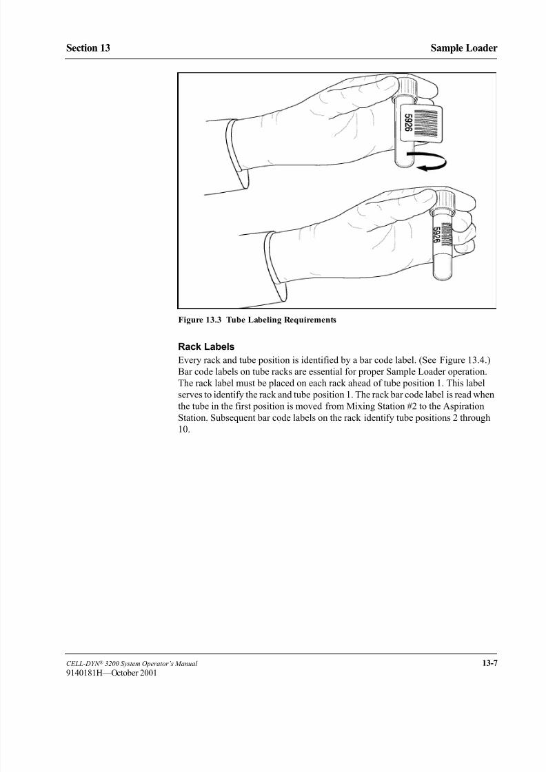
8/21/2019 Equ22-14 CellDyn3200 Op Man
http://slidepdf.com/reader/full/equ22-14-celldyn3200-op-man 575/690
CELL-DYN ® 3200 System Operator’s Manual 13-7
9140181H—October 2001
Section 13 Sample Loader
Figure 13.3 Tube Labeling Requirements
Rack Labels
Every rack and tube position is identified by a bar code label. (See Figure 13.4.)
Bar code labels on tube racks are essential for proper Sample Loader operation.
The rack label must be placed on each rack ahead of tube position 1. This label
serves to identify the rack and tube position 1. The rack bar code label is read when
the tube in the first position is moved from Mixing Station #2 to the AspirationStation. Subsequent bar code labels on the rack identify tube positions 2 through
10.

8/21/2019 Equ22-14 CellDyn3200 Op Man
http://slidepdf.com/reader/full/equ22-14-celldyn3200-op-man 576/690
13-8 CELL-DYN ® 3200 System Operator’s Manual
9140181H—October 2001
Sample Loader
Sample Loader Description Section 13
Figure 13.4 Rack with Bar Code Labels
NOTE: Tube bar code labels must be ≥ 3 digits. Rack labels must include Code
39. The Rack ID must be 2 digits, and the rack position must be 1 digit.
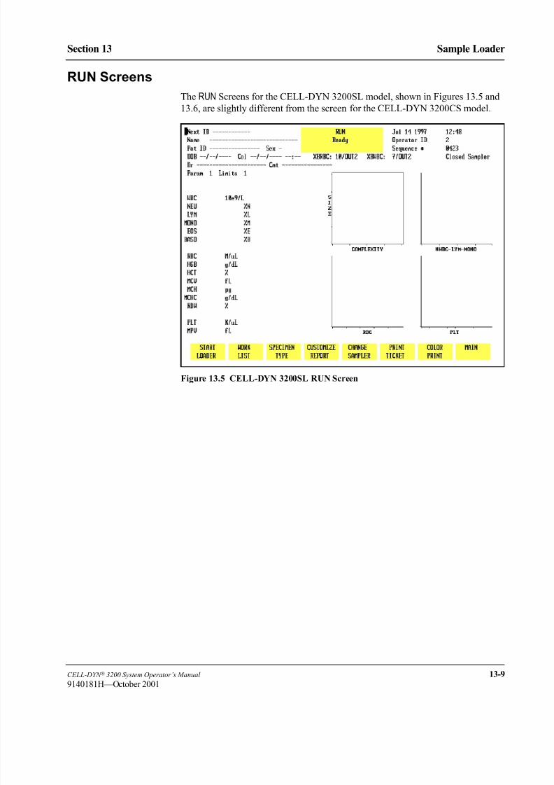
8/21/2019 Equ22-14 CellDyn3200 Op Man
http://slidepdf.com/reader/full/equ22-14-celldyn3200-op-man 577/690
CELL-DYN ® 3200 System Operator’s Manual 13-9
9140181H—October 2001
Section 13 Sample Loader
RUN Screens
The RUN Screens for the CELL-DYN 3200SL model, shown in Figures 13.5 and
13.6, are slightly different from the screen for the CELL-DYN 3200CS model.
Figure 13.5 CELL-DYN 3200SL RUN Screen

8/21/2019 Equ22-14 CellDyn3200 Op Man
http://slidepdf.com/reader/full/equ22-14-celldyn3200-op-man 578/690
13-10 CELL-DYN ® 3200 System Operator’s Manual
9140181H—October 2001
Sample Loader
Sample Loader Description Section 13
Figure 13.6 Sample Loader Restart Screen
Soft Keys
Overview
The soft key menu on the CELL-DYN 3200SL model is similar to the menu on the
CELL-DYN 3200CS model except for the following:
1. The [START LOADER/STOP LOADER] key in the first position (refer to Figure
13.5).
NOTE: The [CLEAR FAULT] key will appear in the first position whenever a
Fault condition occurs.
2. A submenu that appears under certain conditions when the [START LOADER] key is pressed (refer to Figure 13.6).
Pressing the [START LOADER] key activates the Sample Loader and toggles to
[STOP LOADER] without an intervening submenu under the following two
conditions:
1. When the System has been initialized or when only the Sample Loader has been re-initialized.
2. When the Sample Loader has finished processing all loaded racks (without
the [STOP LOADER] key being pressed) and comes to a halt.

8/21/2019 Equ22-14 CellDyn3200 Op Man
http://slidepdf.com/reader/full/equ22-14-celldyn3200-op-man 579/690
CELL-DYN ® 3200 System Operator’s Manual 13-11
9140181H—October 2001
Section 13 Sample Loader
Start Loader
Pressing the [START LOADER] key displays the RESTART menu shown in Figure
13.6 (the Sample Loader remains inactive) under the following two conditions:
1. When the [STOP LOADER] key was pressed while the Sample Loader was
operating
2. When the [CLEAR FAULT] key was pressed.
Stop Loader
When the [STOP LOADER] key is pressed, the Sample Loader comes to a halt after
the current sample cycle is completed and the key changes to [START LOADER].
Restarting the Loader
Pressing the [START LOADER] key after the [STOP LOADER] or [CLEAR FAULT] key
was pressed will not automatically activate the Sample Loader. Instead, the Sample
Loader RESTART menu (refer to Figure 13.6) is displayed with three soft keys:
RESUME LOADERRESET LOADER
RETURN
NOTE: If a Sample Loader fault occurs, when the [CLEAR FAULT] and [STARTLOADER] keys are pressed one of two possible submenus will be
displayed. Refer to Sample Loader Faults later in this section for an
explanation.
The operator must decide which key to press to re-activate the Sample Loader
based on whether or not the rack under the Tower was moved. Pressing either
[RESUME LOADER] or [RESET LOADER] will activate the Sample Loader and
display the main RUN screen with the [STOP LOADER] key again displayed in the
first position.
Resume Loader
The [RESUME LOADER] key should be used to activate the Sample Loader under the
following conditions:
1. When the [STOP LOADER] key was pressed and the rack under the Tower was
not subsequently moved.
2. When a Sample Loader fault occurred that did not require re-initializing the
loader.
In this case, sample processing will resume from the point where the last specimen
was aspirated. If any tubes are detected in either Mixing Station, the sample(s) will be mixed prior to the rack advancing.
NOTE: If the rack was moved and the [RESUME LOADER] key is pressed, a Fault
condition will occur.

8/21/2019 Equ22-14 CellDyn3200 Op Man
http://slidepdf.com/reader/full/equ22-14-celldyn3200-op-man 580/690
13-12 CELL-DYN ® 3200 System Operator’s Manual
9140181H—October 2001
Sample Loader
Sample Loader Description Section 13
Reset Loader
The [RESET LOADER] key should be used to activate the Sample Loader under the
following conditions:
1. When the [STOP LOADER] key was pressed and the rack under the Tower was
subsequently moved
2. When a Sample Loader fault occurred that required re-initializing the loader.
If the rack must be moved for any reason, it should be completely removed and
placed in the starting position on the load side (or a new rack must be in the starting
position). If the Sample Loader must be re-initialized after a fault, the Tower must
be cleared and all racks placed on the load side. The [RESET LOADER] key re-
initializes the Sample Loader before activating the loader transport mechanism.
NOTE: If a rack is still under the Tower and the [RESET LOADER] key is pressed,
a Fault condition will occur.
Return
The [RETURN] key on the RUN screen submenu returns the operator to the main RUN screen with the [START LOADER] key in the first position.
Fault Conditions
On the SL model, there are two sources of fault conditions: Instrument-related
faults (Data Module or Analyzer) and Sample Loader-only faults.
Data Module/Analyzer Faults
Faults related to the Data Module or Analyzer may be either operator-correctable
or fatal.
If the fault is operator-correctable, when [START LOADER] is pressed the RESTART
menu is displayed with the choice of either resuming or resetting the sample loader.
In the case of fatal faults, the entire system must be re-initialized or rebooted. Any
rack under the Tower must be removed and placed in the starting position on the
load side.
Sample Loader Faults - Reset Loader
When a fault occurs in the Closed Mode, the [CLEAR FAULT] key replaces the [STOPLOADER] key. Some Sample Loader-only faults require the Sample Loader to be re-
initialized. In this case, when the operator presses the [CLEAR FAULT] key followed
by [START LOADER], a submenu is displayed showing only the [RESET LOADER] and [RETURN] keys. The [RESUME LOADER] key is not displayed because any rack
under the Tower must be removed and placed in the starting position on the Loadside. Refer to Restarting the Loader for a discussion on using the RESET key.

8/21/2019 Equ22-14 CellDyn3200 Op Man
http://slidepdf.com/reader/full/equ22-14-celldyn3200-op-man 581/690
CELL-DYN ® 3200 System Operator’s Manual 13-13
9140181H—October 2001
Section 13 Sample Loader
Sample Loader Faults - Resume Loader
Some Sample Loader-only faults do not require the Sample Loader to be re-
initialized. In these cases, when the operator presses the [CLEAR FAULT] key
followed by [START LOADER], a submenu is displayed showing both the [RESUMELOADER] and [RESET LOADER] keys as well as [RETURN]. The operator has the
option of using either RESUME or RESET to activate the Sample Loader. Refer to Restarting the Loader for a discussion of when to use the RESUME key versus the
RESET key.
Processing Stations
There are three processing stations on the Sample Loader. These stations are
described below and shown in Figure 13.7. Mixing Station 1 corresponds to the
first tube gripper in the Mixing Block and Mixing Station 2 corresponds to the
second tube gripper.
Station 1, First Mixing: A sensor detects the presence of a tube and activates
the mixer. The sample is mixed in a 135° rotation for
approximately 40 seconds.
Station 2, Second Mixing: A second sensor detects the presence of a tube and
activates the mixer. The sample is again mixed in a
135° rotation for approximately 40 seconds.
NOTE: Several Sample Loader-related error messages refer to tube positions 3
and 4, which are Mixing Stations 1 and 2 respectively.
(Refer to Figure 13.7.)
Station 3, Vent/Aspiration: The tube is positioned for aspiration. The bar code is
read. The spinner mechanism descends, detects the
tube height, grips and spins the tube, allowing the Bar
Code Reader to read the label. The tube stopper is punctured by the Vent/Aspiration Needle (the
“Needle”) in the Tower Module. The tube is vented
and the sample is aspirated.
These three stations are adjacent to each other. Each sample is mixed twice before
being vented and aspirated.

8/21/2019 Equ22-14 CellDyn3200 Op Man
http://slidepdf.com/reader/full/equ22-14-celldyn3200-op-man 582/690
13-14 CELL-DYN ® 3200 System Operator’s Manual
9140181H—October 2001
Sample Loader
Sample Loader Description Section 13
Figure 13.7 Sample Loader Stations
Rack Movement
The tube racks move from the load side, through the mixing and aspiration stations,
to the unload side (refer to Figure 13.8). The rack closest to the Analyzer on the
load side is the first to be processed. This is the starting position for a rack.
Load Side
A set of mechanical arms on the load side pushes the racks forward toward the
Analyzer. If the arms do not sense a rack on the load side, the Sample Loader emits
3 beeps to alert the operator and displays a message on the Bulletin line stating
Loader Status 158: load zone empty.
Additionally, when the last rack has been processed, the message “Loader
Status 143: Samples completed” may be displayed on the bulletin line.
1 Tube Sensors (behind
Stations 1 & 2)
2 Station 1 (tube position
3)
3 Station 2 (tube position
4)
4 Station 3
5 Bar Code Reader 1
2
3
4
5

8/21/2019 Equ22-14 CellDyn3200 Op Man
http://slidepdf.com/reader/full/equ22-14-celldyn3200-op-man 583/690
CELL-DYN ® 3200 System Operator’s Manual 13-15
9140181H—October 2001
Section 13 Sample Loader
Figure 13.8 Rack Movement
Mixing and Aspiration Stations
A pneumatic-actuated mechanism advances the rack one position at a time through
the mixing and aspiration stations. As the rack advances through the Mixing
Stations, sensors detect if a tube is at Mixing Station #1 or Mixing Station #2.
If a tube is detected at either station, the Mixer descends, grabs one or both tubes,
and mixes for approximately 40 seconds. Each tube is mixed twice, once at each
mixing station. After being mixed at the second Mixing Station the tube advances
to the Aspiration Station where it is vented and aspirated.
When the 6th tube is at Station 3 (aspiration), the next rack on the load side is
pushed forward in preparation for processing. Racks continue moving to the
preparation position until either the load side is empty or the unload side is full.
After the last tube in a rack has been processed, the rack continues moving until it
reaches the left edge of the Sample Loader. At this point, the rack is pushed to the
most forward position of the unload side to make room for the next racks.
1 Rack Advance
2 Unload Side
3 Racks are pushed
away from the
Analyzer
4 Load Side
5 Racks are pushed
toward the Analyzer
6 Aspiration Needle
7 Mixing Block
8 Station 1
9 Station 2
10 Station 3
11 Bar Code Reader
1 1
42
3 5
6 7
8
9
1011

8/21/2019 Equ22-14 CellDyn3200 Op Man
http://slidepdf.com/reader/full/equ22-14-celldyn3200-op-man 584/690
13-16 CELL-DYN ® 3200 System Operator’s Manual
9140181H—October 2001
Sample Loader
Sample Loader Description Section 13
If a malfunction occurs at the Mixing or Aspiration Stations, the Sample Loader
halts operation and emits a beep to alert the operator. The [CLEAR FAULT] key is
displayed, and a fault message is displayed on the bulletin line.
Unload Side
When the rack reaches the edge of the left side, a mechanical arm pushes the racktoward the front of the Sample Loader to make room for the next rack being
processed. The unload side can accommodate 5 racks. A 5th rack, however, will
prevent a 6th rack from being completely processed by interfering with that rack’s
movement through the Mixing and Aspiration Stations.
If the unload side is full (5 racks) and a 6th rack is being processed, the 6th rack
can advance until the 6th tube position is at the Aspiration Station (refer to Figure
13.9). If position 6 has a sample, then that sample can be processed. When
processing is completed for that sample, the Sample Loader will emit 3 beeps to
alert the operator that the unload side is full and the Sample Loader has stopped.
The [CLEAR FAULT] key is displayed, and the message Loader Warning 145:
unload area full is displayed on the bulletin line. The operator must removeracks from the unload side for the 6th rack to be completely processed.
Figure 13.9 Unload Side Full
1 Unload Side
2 Load Side
3 Aspiration Needle
4 Mixing Block
5 Station 1
6 Station 2
7 Station 3
8 Bar Code Reader
1 2
3
87
6
5
4
8/21/2019 Equ22-14 CellDyn3200 Op Man
http://slidepdf.com/reader/full/equ22-14-celldyn3200-op-man 585/690
CELL-DYN ® 3200 System Operator’s Manual 13-17
9140181H—October 2001
Section 13 Sample Loader
Sample Identification
Each rack must have a legible bar code label. If a rack has no bar code label or if
the label cannot be read by the Bar Code Reader, the Sample Loader stops, and the
message Loader Fault 153: rack barcode read failure
is
displayed on the bulletin line. No samples have been aspirated at this point.
The rack bar code label identifies each rack by number. The system tracks the rack
number and tube position for each sample placed in the rack from the bar code
reader signal.
The Sample Loader provides sample identification using an LED-based Bar Code
Reader at Station 3 (tube spinning/aspiration). As each tube reaches Station 3, the
sample tube is rotated and the bar code reader is turned ON to read the bar code
label on the tube. If no bar code label is present or the label is unreadable, the
sample is identified by the rack number and tube position, in the format RxTx, on
the RUN screen and in the DATA LOG.
Operation of the Sample Loader with non-bar-coded samples is allowed. However,
the use of bar code labels is recommended for positive sample identification. Referto Section 5: Operating Instructions; Subsection: Using The Work List for a
discussion of using the Work List with and without bar code labels for sample
identification.
Normally, non-bar-coded samples should not be removed from the racks until all
samples have been processed since the rack and tube number of each sample is
important for positive sample identification.
If the rack being processed (under the Tower Cover) must be removed before
processing is completed (for example, the system must be re-initialized to clear a
Fatal Fault condition), make a note of which tube was under the Aspiration Needle
before removing the rack. Follow the guidelines below:
1. Make sure the Sample Loader has stopped and the Aspiration Needle has
retracted. Remove the Tower Cover if necessary.
2. If a fault occurred, correct the situation and press [CLEAR FAULT].
3. If bar code labels are used for identification:
a. Check the Work List to determine if the entries corresponding to the
processed samples have been deleted, indicating a match occurred and
the data was sent to the Data Log. It is permissible to remove those
samples before returning the rack to the starting position.
b. Move the remaining tubes to the front of the rack and place the rack in
the starting position.
c. Go to step 5.
4. If rack and tube numbers are used for identification:
a. Check the Work List to determine if the entries corresponding to the
processed samples, based on rack and tube number, have been deleted,
indicating a match occurred and the data was sent to the Data Log. It is
permissible to remove those samples before returning the rack to the
starting position.

8/21/2019 Equ22-14 CellDyn3200 Op Man
http://slidepdf.com/reader/full/equ22-14-celldyn3200-op-man 586/690
13-18 CELL-DYN ® 3200 System Operator’s Manual
9140181H—October 2001
Sample Loader
Sample Loader Description Section 13
b. DO NOT move the remaining tubes in the rack, otherwise Work List
entries will also have to be changed to reflect the new rack and tube
positions of the remaining samples. Place the rack in the starting
position.
5. Replace the Tower Cover and press [START LOADER] followed by [RESET
LOADER] to resume operations.
Stopping the Sample Loader
The Sample Loader automatically halts when all loaded racks have been processed.
There are three ways to stop the Sample Loader during processing, as described
below:
1. Power OFF. Turn the Main Power Switch on the Analyzer to OFF. This
method is not recommended unless there is an emergency.
2. Orderly Stop. Press [STOP LOADER] for an orderly stop. Orderly stops allow
to complete aspiration of the sample that is currently or has been mixed in
Mixing Station 2 and finish the vent/aspiration/cleaning process. The [STARTLOADER] soft key appears and you should press it to start the sample loading
process again.
3. Emergency Stop. Remove the Tower Cover to break the safety interlock
sensor connection. Emergency stops cause the Aspiration Needle to retract if
already in the tube and the Mixer to return the tube(s) to the rack before
bringing the Sample Loader to a halt. To completely remove the cover, lift it
vertically. An emergency stop results in a Fatal Fault condition. To resume
the sampling process:
a. Re-attach the Tower Cover.
b. Re-initialize and prime the instrument. The Sample Loader is
automatically initialized when the Analyzer is initialized.NOTE: To initialize the instrument, in the main DIAGNOSTICS MENU
press [MORE] followed by [INITIALIZATION]. Refer to Section 10:
Troubleshooting and Diagnostics; Subsection: Second
Diagnostics Menu Screen. To prime the instrument, press
[RUN] in the MAIN MENU.
c. Move the rack that was under the Tower Cover to the starting position
and remove all processed samples.
d. When the system has been initialized and primed, press [CHANGESAMPLER] in the RUN menu to switch into the Closed Mode.
e. Press [START LOADER] to start processing samples.

8/21/2019 Equ22-14 CellDyn3200 Op Man
http://slidepdf.com/reader/full/equ22-14-celldyn3200-op-man 587/690
CELL-DYN ® 3200 System Operator’s Manual 13-19
9140181H—October 2001
Section 13 Sample Loader
Sample Loader Operation
Prior to activating the Sample Loader, racks containing tubes to be processedshould be placed on the load side of the Sample Loader (refer to Figure 13.8).
Sample Loader Cycle
The following sequence is a basic description of the events that occur from the time
that the instrument is turned ON through the complete processing cycle. During the
cycle, the number of tube racks is monitored by optical interrupt sensors located on
the Transport Mechanisms.
NOTE: The Sample Loader can operate with any number of racks, the minimum
being one.
1. The Sample Loader is initialized each time the instrument is turned ON, eachtime the instrument is re-initialized, and each time it completes a cycle (at
least one rack has moved through the Mixing and Aspiration Stations and no
more racks are detected on the load side).
2. When the Sample Loader has been initialized and is in the READY state, the
message READY is displayed in the Status Box.
3. When the [START LOADER] key in the RUN screen is pressed, the Sample
Loader pushes the rack(s) on the load side closest to the Analyzer.
a. As the rack advances, the sensor at Mixing Station 1 searches for a tube.
b. Even if there are no tubes present in the rack, the Transport Mechanism
continues to move the rack under the Tower Cover until a sample tube is
sensed in Mixing Station 1.c. If a sample tube is detected, the mixing and vent/aspiration mechanisms
will process the sample.
4. The Mixing Head moves down, picks up the tube, and begins mixing it.
5. The sample is mixed by 135° rotation in both Mixing Stations for
approximately 40 seconds. The total mixing time for each sample is
approximately 80 seconds.
NOTE: Tubes with more than three layers of labels on them or with label
flaps sticking out can cause problems for the Mixing Assembly.
The assembly may not be able to pick the tube up because the labels
cause the tube to stick to the rack. The assembly may also have
trouble fitting the tube back into the rack for the same reason.

8/21/2019 Equ22-14 CellDyn3200 Op Man
http://slidepdf.com/reader/full/equ22-14-celldyn3200-op-man 588/690
13-20 CELL-DYN ® 3200 System Operator’s Manual
9140181H—October 2001
Sample Loader
Sample Loader Operation Section 13
6. When a tube has been properly mixed, it moves to the Vent/Aspiration
Station (Station 3).
a. When the Needle begins to move down, the Spinning Assembly moves
down to (a) position the tube so that the stopper is pierced at or near the
center, and to (b) rotate the tube so that the bar code can be read.
b. The needle stops moving while the bar code label is being read.
c. After the label is read, the needle continues moving down. It pierces the
stopper and moves to the bottom of the tube.
d. The Sample Loader signals the Analyzer to vent the tube and aspirate the
sample.
e. The sample is pulled into the Shear Valve by vacuum action. The
Analyzer then begins a normal count cycle.
7. When an empty space is detected by both Mixing Station sensors, the rack
automatically advances without engaging the Mixer. When an empty space is
detected by the sensor on the Tower, the Needle and Spinner are not engaged
as the rack advances. The Mixing Assembly and Tower Assembly will not be
engaged until a tube is sensed at either Mixing Station.
NOTE: The Instrument operates most efficiently when tubes in a rack are
adjacent to one another. Generally, spacing between sample tubes
will have an impact on overall throughput. If there are numerous
empty spaces, then throughput time may be significantly slowed.
8. After the sample is aspirated, the Needle is retracted and washed. As the
Needle moves up, the Spinning Assembly also retracts.
9. Steps 4-8 are repeated until all tubes in the rack have been processed.
10. Regardless of how many tubes are in a rack, when the rack has moved
completely under the Tower Cover, the second rack is moved into position on
the right side of the Cover in preparation for sample processing.11. When all tubes in the last rack have been processed:
a. The Sample Loader automatically stops and emits beeps to alert the
operator that processing is completed
b. The message Loader Status 143: samples completed is
displayed in the bulletin line when the rack has traversed completely to
the unload side.
c. The [STOP LOADER] key toggles to [START LOADER].
d. The Sample Loader is re-initialized.

8/21/2019 Equ22-14 CellDyn3200 Op Man
http://slidepdf.com/reader/full/equ22-14-celldyn3200-op-man 589/690
CELL-DYN ® 3200 System Operator’s Manual 13-21
9140181H—October 2001
Section 13 Sample Loader
Operating Procedures
1. Press the [START LOADER] key in the RUN menu. Based on which condition
exists (refer to the Sample Loader Description, Soft Keys subsection), either
the Sample Loader will be activated or a submenu will be displayed.
2. If the submenu is displayed, press either [RESUME LOADER] or [RESETLOADER] (refer to the Sample Loader Description, Soft Keys subsection for
a discussion of when to use each key).
3. Racks are moved in sequential order from the load side, through the Mixing
and Aspiration Stations to the unload side (refer to Figure 13.8).
4. For sample mixing and aspiration to occur, the sensors must detect a tube in
the rack. The Sample Loader automatically stops after the last rack is
processed and no more racks are detected on the load side.
5. When the tube is at the Vent/Aspiration Station, the Spinner positions the
tube vertically in the rack, spins the tube for bar code reading, and holds the
tube while it is vented and the sample aspirated. Proper positioning is
necessary for the tube stopper to be pierced in the center.6. The Tower Cover on the CELL-DYN 3200SL model fits over the Mixing
Station and Bar Code Reader on the loader. This cover prevents aerosol
contamination and exposure to the needle while the Sample Loader is
processing specimens.
NOTE: The Sample Loader has an interlock switch that prevents operation
when the Tower Cover is not in place. If the Tower Cover is
removed during Sample Loader operation, processing is
immediately halted. For an orderly stop, the operator must press the
[STOP LOADER] key and wait for the Sample Loader and Analyzer
to stop processing before lifting or removing the cover. Lifting the
cover while the Sample Loader is operating causes an immediate
Emergency Stop condition. The entire system must be re-initialized.

8/21/2019 Equ22-14 CellDyn3200 Op Man
http://slidepdf.com/reader/full/equ22-14-celldyn3200-op-man 590/690
13-22 CELL-DYN ® 3200 System Operator’s Manual
9140181H—October 2001
Sample Loader
Sample Loader Operation Section 13
NOTES
8/21/2019 Equ22-14 CellDyn3200 Op Man
http://slidepdf.com/reader/full/equ22-14-celldyn3200-op-man 591/690
CELL-DYN ® 3200 System Operator’s Manual 13-23
9140181H—October 2001
Section 13 Sample Loader
Routine Operating Procedures
InstallationFor detailed instructions on how to install the SL model, refer to Section 2:
Installation Procedures and Special Requirements.
Running Samples
Instructions for Routine Operation of the CELL-DYN 3200SL model are given in
Section 5: Operating Instructions.
Maintenance
Maintenance procedures on the SL model should be performed as directed in
Section 9: Service and Maintenance. These procedures consist of cleaning the
Tower Cover, the Needle, the Tube Grippers, the tray and the tube racks. If the
Vent/Aspiration Needle requires replacement, refer to Section 9: Service and
Maintenance; Subsection: Closed Sample Needle Replacement .
Troubleshooting
If a Sample Loader fault, error or other problem is detected, an alert message is
displayed on the bulletin line of the screen. For a list of messages, descriptions of
possible problems and recommended actions, refer to Section 10:
Troubleshooting and Diagnostics.

8/21/2019 Equ22-14 CellDyn3200 Op Man
http://slidepdf.com/reader/full/equ22-14-celldyn3200-op-man 592/690
13-24 CELL-DYN ® 3200 System Operator’s Manual
9140181H—October 2001
Sample Loader
Routine Operating Procedures Section 13
NOTES

8/21/2019 Equ22-14 CellDyn3200 Op Man
http://slidepdf.com/reader/full/equ22-14-celldyn3200-op-man 593/690
CELL-DYN ® 3200 System Operator’s Manual 14-1
9140181H—October 2001
Section 14 Reticulocyte Package
ec on et cu ocyte ac age
Overview
The Reticulocyte Package software enables the operator of the CELL-DYN 3200System to analyze a whole blood specimen for reticulocytes. The Reticulocyte
specimen is prepared by using reticulocyte reagent to produce a diluted, stained
sample. Reticulocyte specimens can be run as batches, or they can be run on a
STAT basis.
The Reticulocyte Package is enabled by pressing [TURN ON RETIC PKG] from the
OPERATION SET UP MENU screen.
Each menu and function is modified when used in the Reticulocyte Package.
Therefore, some of the soft keys that are displayed in the Standard Hematology
Mode will be available from the different Reticulocyte screens, and some will not.
A Reticulocyte Data Log and a Reticulocyte QC Log are available for samples and
controls run within the Reticulocyte Package. Descriptions of all Reticulocyte softkeys are included in this chapter.
The prepared specimen run with the Reticulocyte Package on the
CELL-DYN 3200 System will measure results as a reticulocyte percentage. The
reticulocyte absolute number is automatically calculated when the RBC value is
made available from the Standard Hematology Data Log or entered by the operator.
The CELL-DYN 3200 System can be returned to the Standard Hematology
function by pressing [TURN OFF RETIC PKG] from the OPERATION SET UP MENU
screen.
Section Contents
This section contains the following subsections:
• Principles of Operation
• Flowchart Conventions
• Retic Menu Options
– Turning the Reticulocyte Package ON and OFF
– All Retic Menus Except the RETIC RUN Menu
• Routine Operation
– RETIC RUN Menu
– Reticulocyte Specimens
• Quality Control Guide
• Troubleshooting
8/21/2019 Equ22-14 CellDyn3200 Op Man
http://slidepdf.com/reader/full/equ22-14-celldyn3200-op-man 594/690
14-2 CELL-DYN ® 3200 System Operator’s Manual
9140181H—October 2001
Reticulocyte Package
Overview Section 14
NOTES

8/21/2019 Equ22-14 CellDyn3200 Op Man
http://slidepdf.com/reader/full/equ22-14-celldyn3200-op-man 595/690
CELL-DYN ® 3200 System Operator’s Manual 14-3
9140181H—October 2001
Section 14 Reticulocyte Package
Principles of Operation
The Reticulocyte Package software is designed to configure the instrument to process stained, diluted specimens. When the Reticulocyte Package is turned ON,
the instrument automatically selects the appropriate configuration file and adjusts
the instrument settings to the values in this file. This configuration is retained until
the Reticulocyte Package is turned OFF. The instrument then returns to the
Standard Hematology settings.
Reticulocytes are defined by the National Committee for Clinical Laboratory
Standards (NCCLS) as transitional red cells, between nucleated red cells and the
so-called mature erythrocytes1. In contrast to mature RBCs, reticulocytes contain
ribosomal RNA. This RNA can be seen with certain supravital, cationic dyes that
simultaneously stain and precipitate the polyanion to form a network or reticulum.
The CELL-DYN 3200 System reticulocyte method uses the thiazine dye NewMethylene Blue N. The reticulocyte assay is performed in the WOC channel of the
instrument. Sample preparation is performed manually by dispensing 20 µL of
blood into a tube of CELL-DYN Reticulocyte Reagent. At room temperature,
staining of reticulum is complete within approximately 15 minutes. The stained
sample is aspirated in the Open Mode. After the stained sample is aspirated, it is
diluted approximately 50-fold with WBC Lyse Reagent. Once diluted with WBC
Lyse, the RBCs sphere due to the influence of the nonionic detergent incorporated
into the staining solution. Sphering is necessary to eliminate optical orientational
noise that would otherwise be introduced into the scatter measurements. The usual
lytic action of the WBC Lyse is prevented by electrolytes contained in the staining
solution and the lack of the usual incubation period used in this channel during
WBC analysis. In addition, the high New Methylene Blue concentration in thestaining reagent exerts a stabilizing effect on RBCs.
During data acquisition, 0 degree, 10 degree, and 90 degree scatter are collected for
up to 30,000 events. The 0 degree threshold is set high enough to exclude most
platelets. Histogram data are used to differentiate reticulocytes, mature RBCs,
platelet clumps, and nucleated cells. Reticulocytes have 10 degree scatter that are
similar to the scatter for mature RBCs, but differ from them by exhibiting greater
90 degree scatter. Reticulocytes are reported in percent. The instrument will
automatically calculate the Reticulocyte Absolute value if an RBC count is entered.
The RBC value may be obtained from the Standard Hematology Data Log, or it
may be entered by the operator directly on the RETIC PATIENT SPECIMEN screen.

8/21/2019 Equ22-14 CellDyn3200 Op Man
http://slidepdf.com/reader/full/equ22-14-celldyn3200-op-man 596/690
14-4 CELL-DYN ® 3200 System Operator’s Manual
9140181H—October 2001
Reticulocyte Package
Principles of Operation Section 14
Flowchart Conventions
Menus are shown as square-cornered rectangles in the flowcharts, and soft keys are
shown as round-cornered rectangles:
When procedures are depicted in flowcharts, shaded boxes and bold lines indicate
which soft keys to press:
Flowcharts
The Reticulocyte Package master menu flowchart on the following page was
designed to help guide the operator quickly and easily through the menu levels and
soft key functions used in the Reticulocyte Package. A segment of this flowchart is
included at the beginning of each submenu description to guide the operator
through the levels and functions of each submenu and back again to the MAINMENU. The master menu flowchart can be used as a pull-out guide.
MAIN MENU
Ready
SET UP RUN DATA LOG QUALITY
CONTROLRETIC
DATA LOGCALIBRATION SPECIAL
PROTOCOLSDIAG-
NOSTICS
MAIN MENU
PATIENT REAGENTLOG
QC SETUP MENU
OPERATION
SET UP
SET UP RUN DATA LOG QUALITY
BAR CODE
SET UP
CONTROL
LIMITS
RETICDATA LOG
CALIBRATION SPECIAL
PROTOCOLSDIAG-
NOSTICS
TURN ONRETIC PKG

8/21/2019 Equ22-14 CellDyn3200 Op Man
http://slidepdf.com/reader/full/equ22-14-celldyn3200-op-man 597/690
CELL-DYN ® 3200 System Operator’s Manual 14-5
9140181L—July 2003
Section 14 Reticulocyte Package
S A M E K E Y S
A S I N
H E M A T O L O G Y
C E L L - D Y N 3 2 0 0 S y s t e m
R e t i c u l o c y t e M e n u F l o w c h a r t
R E T I C
M A I N
E D I T I D
D I S P L A Y
S P E C I M E N
Q C
C L E A R
F A U L T S
P A T I E N T
S P E C I M E N
R E T I C M A I N
R E T I C
S E T U P
R E T I C
D I A G N O S
T I C
R E T I C S P
P R O T O C O L S
R E T I C
R U N
R E T I C
D A T A L O G
R E T I C
Q C
R E
T I C
F A U L T S
R E P O R T
M A
I N
R E T I C
E M P T Y / F I L L
F L O W
C E L L
R E T I C
M A I N
D I S A B L E
A N A L Y Z E R
M A I N
C L E A N / R E S
S H E A R V A L V E
E X E C U T I O N
T I M E S
C L E A R
F A U L T S
R E T I C
C N T R A T E
R E T I C
R A W
D A T A
D A T A
L O G
B A C K -
G R O U N D
R E T I C M A I N
F I N D
S P E C I M E N
T R A N S M
I T
D A T A
P R I N T
D A T A L O G
S P E C I M E N
R E T I C
V I E W
Q C L O G
Q C F I L E
S E T U P
R E T I C
M A I N
Q C L I M I T S
R E A G E N T
R E S E R V O I R
E N A B L E
A N A L Y Z E R
D A T E /
T I M E
R E T
I C P T
L I M
I T S
R E A G E N T
L O G
R E T I C Q C
S E T U P
O P E R A T I O N
S E T U P
U N I T S
S E L E C T I O N
C U S T O M I Z E
R E P O R T
R E T I C
M A I N
S A M E K E Y S
A S I N
H E M A T O L O G
Y
R E T I C Q C
Q C F I L E
S E T U P
R E T U R N
L I M I T S
R A N G E
M E A N S /
L I M I T S
U P D A T E
L O A D
F R O M F I L E
E N T R Y
L I M I T
S E T 1
L I M I T
S E T 2
L I M I T
S E T 3
L I M I T
S E T 4
L I M I T
S E T 5
L I M I T
S E T 6
P R I N T
R E T U R N
D E L E T E
E N T R Y
D I L / S H E A T H
L O G
H G B L Y S E
L O G
W B C L Y S E
L O G
P R I N T
L O G
R E T U R N
T U R N O F F
R E T I C P K G
L A N G U A G E
S E L E C T
C O L O R
B A R C O D E
S E T U P
C O M P U T E R
S E T U P
R E T U R N
P R I N T
R E T U R N
F
R O M D I S K
R E P L I C A T E
T
O G G L E
O N / O F F
P R I N T
I D
R E T U R N
L O T
N U M B E R

8/21/2019 Equ22-14 CellDyn3200 Op Man
http://slidepdf.com/reader/full/equ22-14-celldyn3200-op-man 598/690
14-6 CELL-DYN ® 3200 System Operator’s Manual
9140181H—October 2001
Reticulocyte Package
Principles of Operation Section 14
NOTES

8/21/2019 Equ22-14 CellDyn3200 Op Man
http://slidepdf.com/reader/full/equ22-14-celldyn3200-op-man 599/690
CELL-DYN ® 3200 System Operator’s Manual 14-7
9140181H—October 2001
Section 14 Reticulocyte Package
Retic Menu Options
This section discusses the operation of the Reticulocyte Package. It contains thefollowing subsections:
• Turning the Reticulocyte Package ON and OFF
• RETIC MAIN Menu
• RETIC SET UP Menu
• RETIC DATA LOG Menu
• RETIC QC LOG Menu
• RETIC DIAGNOSTICS Menu
• RETIC SPECIAL PROTOCOLS Menu
For information about the RETIC RUN menu, refer to Routine Operation, Retic Run
Menu later in this chapter. For specific instructions about running Reticulocyte
specimens, refer to Routine Operation, Reticulocyte Specimens later in this
chapter.
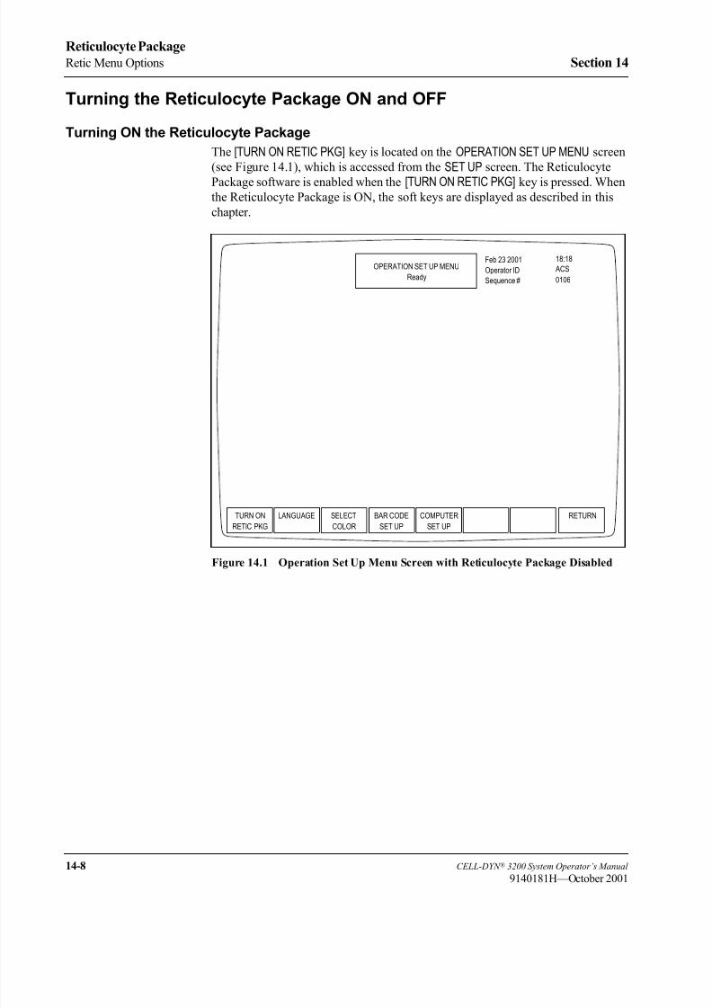
8/21/2019 Equ22-14 CellDyn3200 Op Man
http://slidepdf.com/reader/full/equ22-14-celldyn3200-op-man 600/690
14-8 CELL-DYN ® 3200 System Operator’s Manual
9140181H—October 2001
Reticulocyte Package
Retic Menu Options Section 14
Turning the Reticulocyte Package ON and OFF
Turning ON the Reticulocyte Package
The [TURN ON RETIC PKG] key is located on the OPERATION SET UP MENU screen
(see Figure 14.1), which is accessed from the SET UP screen. The Reticulocyte
Package software is enabled when the [TURN ON RETIC PKG] key is pressed. When
the Reticulocyte Package is ON, the soft keys are displayed as described in this
chapter.
Figure 14.1 Operation Set Up Menu Screen with Reticulocyte Package Disabled
TURN ON
RETIC PKG
OPERATION SET UP MENU
Ready
Feb 23 2001
Operator ID
Sequence #
18:18
0106
ACS
LANGUAGE SELECT
COLOR
BAR CODE
SET UP
COMPUTER
SET UP
RETURN

8/21/2019 Equ22-14 CellDyn3200 Op Man
http://slidepdf.com/reader/full/equ22-14-celldyn3200-op-man 601/690
CELL-DYN ® 3200 System Operator’s Manual 14-9
9140181H—October 2001
Section 14 Reticulocyte Package
Procedure: Turning ON the Reticulocyte Package
1. From the MAIN MENU, press the [SET UP] key followed by the [OPERATIONSET UP] key to display the OPERATION SET UP MENU screen.
2. From the OPERATION SET UP MENU screen, press the [TURN ON RETIC PKG] key to enable the Reticulocyte Package.
3. The RETIC MAIN menu screen displays.
The software to analyze reticulocytes is now enabled on the CELL-DYN 3200
System.
MAIN MENU
DATE/ UNITS
SELECTION
CUSTOMIZE
REPORT
PATIENT
LIMITS SET UP
OPERATION MAINREAGENT
LOGQC SET
UP MENU
SET UP
DIAGNOSTICS SPECIAL
PROTOCOLSRUN
CALIBRA-
DATA LOGQUALITY
TURN ON
RETIC PKG
LANGUAGE
SET UP
COMPUTER RETURNSELECT
COLORBAR CODE
SET UP
CONTROL TION
TIME
RETICDATA LOG
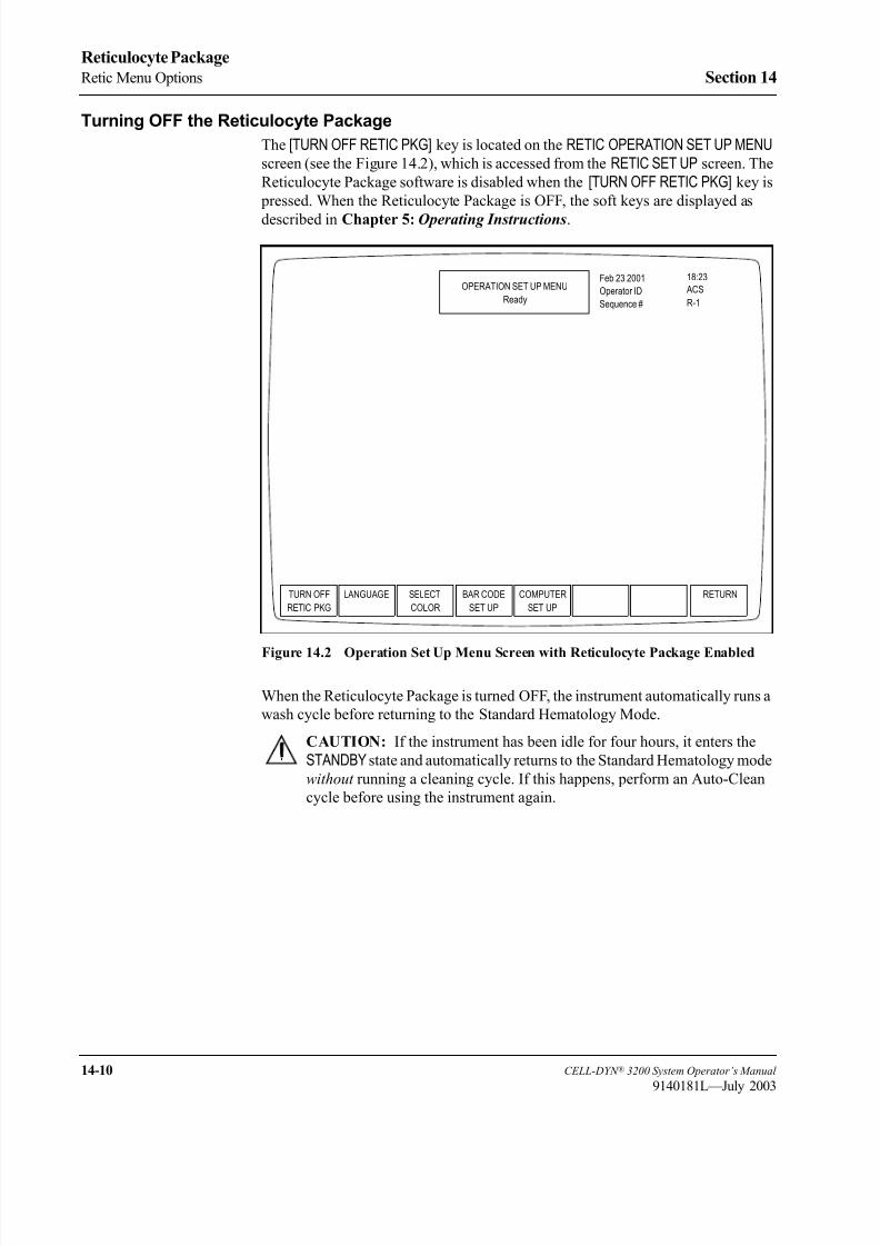
8/21/2019 Equ22-14 CellDyn3200 Op Man
http://slidepdf.com/reader/full/equ22-14-celldyn3200-op-man 602/690
14-10 CELL-DYN ® 3200 System Operator’s Manual
9140181L—July 2003
Reticulocyte Package
Retic Menu Options Section 14
Turning OFF the Reticulocyte Package
The [TURN OFF RETIC PKG] key is located on the RETIC OPERATION SET UP MENU
screen (see the Figure 14.2), which is accessed from the RETIC SET UP screen. The
Reticulocyte Package software is disabled when the [TURN OFF RETIC PKG] key is
pressed. When the Reticulocyte Package is OFF, the soft keys are displayed as
described in Chapter 5: Operating Instructions.
Figure 14.2 Operation Set Up Menu Screen with Reticulocyte Package Enabled
When the Reticulocyte Package is turned OFF, the instrument automatically runs a
wash cycle before returning to the Standard Hematology Mode.
CAUTION: If the instrument has been idle for four hours, it enters the
STANDBY state and automatically returns to the Standard Hematology mode
without running a cleaning cycle. If this happens, perform an Auto-Clean
cycle before using the instrument again.
TURN OFF
RETIC PKG
OPERATION SET UP MENU
Ready
Feb 23 2001
Operator ID
Sequence #
18:23
R-1
ACS
LANGUAGE SELECT
COLOR
BAR CODE
SET UP
COMPUTER
SET UP
RETURN

8/21/2019 Equ22-14 CellDyn3200 Op Man
http://slidepdf.com/reader/full/equ22-14-celldyn3200-op-man 603/690
CELL-DYN ® 3200 System Operator’s Manual 14-11
9140181H—October 2001
Section 14 Reticulocyte Package
Procedure: Turning OFF The Reticulocyte Package
1. From the RETIC MAIN menu screen, press the [RETIC SET UP] key followed by
the [OPERATION SET UP] key to display the OPERATION SET UP MENU screen.
2. From the OPERATION SET UP MENU screen, press the [TURN OFF RETIC PKG] key to disable the Reticulocyte Package. The instrument automatically rinses,
runs a background, and returns to the Standard Hematology Software.
3. The MAIN MENU displays.
The software to analyze reticulocytes is now disabled on the CELL-DYN 3200
System.
CD3200 RETIC MAIN MENU
SELECTION
REAGENT
LOG SET UP
OPERATIONREPORT
RETIC QCSET UP
SET UP DIAGNOSTIC RETIC SPPROTOCOLSRUN DATA LOG
TURN OFF
RETIC PKG
SET UPCOMPUTER RETURNSELECTCOLOR
DATA LOGRETIC
RETIC RETIC RETICQC
RETIC
CUSTOMIZEUNITSDATE/TIME RETIC PTLIMITS MAIN
RETIC
LANGUAGE SET UPBAR CODE
Ready

8/21/2019 Equ22-14 CellDyn3200 Op Man
http://slidepdf.com/reader/full/equ22-14-celldyn3200-op-man 604/690
14-12 CELL-DYN ® 3200 System Operator’s Manual
9140181H—October 2001
Reticulocyte Package
Retic Menu Options Section 14
Retic Main Menu
Figure 14.3 Reticulocyte Main Menu Screen
The upper left-hand corner of the RETIC MAIN menu screen shows the current
revision of the instrument software. The upper right-hand corner shows the current
date and time, the current operator ID, and the Reticulocyte Sequence Number. The
information in the upper right-hand corner is displayed on every screen duringoperation of the Reticulocyte Package.
The Status Box is displayed in the top center of the screen. This box appears on
every screen to show the following information:
• Menu in use (such as RETIC MAIN)
• Analyzer status (such as Ready)
• Other applicable information (such as report or file identity and any existing
fault conditions)
The cursor is positioned at the <OPERATOR ID> field when the RETIC MAIN menu
screen is displayed. An operator ID of up to three alphanumeric characters can beentered. Press the Enter key on the keyboard to accept this operator ID. This
operator ID will be displayed on all other Reticulocyte Package screens and printed
on all reports.
RETIC
SET UP
CD3200 RETIC MAIN MENU
Ready
Feb 23 2001
Operator ID
Retic Seq#
18:27
R-1
ACS
RETIC RETIC
DATA LOG
DATA LOG RETIC
QC
RETIC SP
SYSTEM 2.0
RUN
RETIC
DIAGNOSTIC PROTOCOLS

8/21/2019 Equ22-14 CellDyn3200 Op Man
http://slidepdf.com/reader/full/equ22-14-celldyn3200-op-man 605/690
CELL-DYN ® 3200 System Operator’s Manual 14-13
9140181H—October 2001
Section 14 Reticulocyte Package
The following soft key labels are displayed on the RETIC MAIN menu screen:
RETIC SET UP
RETIC RUN
RETIC DATA LOG
DATA LOG
RETIC QC
RETIC DIAGNOSTIC
RETIC SP PROTOCOLS
The RETIC RUN menu is described in Routine Operation later in this chapter.

8/21/2019 Equ22-14 CellDyn3200 Op Man
http://slidepdf.com/reader/full/equ22-14-celldyn3200-op-man 606/690
14-14 CELL-DYN ® 3200 System Operator’s Manual
9140181H—October 2001
Reticulocyte Package
Retic Menu Options Section 14
Retic Set Up Menu
Figure 14.4 Reticulocyte Set Up Screen
RETIC SET UP
CD3200 RETIC MAIN MENU
SAME KEYS AS IN
HEMATOLOGY
DATE/TIME
RETIC PTLIMITS
REAGENTLOG
RETIC QCSET UP
OPERATIONSET UP
UNITSSELECTION
CUSTOMIZEREPORT
RETICMAIN
SAME KEYS AS IN
HEMATOLOGY
RETIC QC QC FILESET UP
RETURNLIMITS
MEANS/LIMITS
UPDATE LOADFROM FILE
LIMITSET 1
LIMITSET 2
LIMITSET 3
LIMITSET 4
LIMITSET 5
LIMITSET 6
PRINT RETURN
DELETEENTRY
DIL/SHEATHLOG
HGB LYSELOG
WBC LYSELOG
PRINTLOG
RETURN
TURN OFFRETIC PKG
LANGUAGE SELECTCOLOR
BAR CODESET UP
COMPUTERSET UP
RETURN
PRINT RETURNFROM DISK
LOT TOGGLEON/OFF
PRINTNUMBER
RETURN
REPLICATEIDRANGE
ENTRY
DATE/TIME
RETIC SET UPReady
Feb 23 2001
Operator ID
Retic Seq#
18:32
R-1 ACS
RETIC PT REAGENT
LOG
RETIC QC
SET UP
OPERATION
SET UP
RETIC
LIMITS
UNITS
SELECTION
CUSTOMIZE
REPORT MAIN
8/21/2019 Equ22-14 CellDyn3200 Op Man
http://slidepdf.com/reader/full/equ22-14-celldyn3200-op-man 607/690
CELL-DYN ® 3200 System Operator’s Manual 14-15
9140181H—October 2001
Section 14 Reticulocyte Package
The following soft keys are displayed on the RETIC SET UP menu screen:
DATE/TIME
RETIC PT LIMITS*
REAGENT LOG
RETIC QC SET UP*
OPERATION SET UP*
UNITS SELECTION
CUSTOMIZE REPORT
RETIC MAIN*
* These soft keys are described in this section as they appear from left to right on
the screen.
NOTE: The [DATE/TIME], [REAGENT LOG], and [CUSTOMIZE REPORT] are
described in Section 5: Operating Instructions; Subsection: Set Up Instructions.
Retic Patient Limits
The [RETIC PT LIMITS] key is used to display the RETIC PATIENT LIMITS screen
(see Figure 14.5). The following soft key labels are displayed on the RETICPATIENT LIMITS screen:
LIMIT SET 1*
LIMIT SET 2
LIMIT SET 3
LIMIT SET 4
LIMIT SET 5
LIMIT SET 6
RETURN
*The soft key label for the limit set currently displayed on the screen is not shown.

8/21/2019 Equ22-14 CellDyn3200 Op Man
http://slidepdf.com/reader/full/equ22-14-celldyn3200-op-man 608/690
14-16 CELL-DYN ® 3200 System Operator’s Manual
9140181H—October 2001
Reticulocyte Package
Retic Menu Options Section 14
Figure 14.5 Reticulocyte Patient Limits Screen
The [RETIC PT LIMITS] key is used to enter upper and lower flagging limits for
groups of patient samples. (For example, limits may be entered for adult males,
adult females, neonates, etc.)
Six sets of limits may be entered. Whenever a result falls outside an entered limit,
the result is displayed in color on the screen to alert the operator. Results displayedin yellow are below the limit and results displayed in purple are above the limit.
The flagged result is underlined on the graphics report and in the Reticulocyte Data
Log when printed. Patient results that exceed the linearity specifications will be
suppressed and chevrons (>>>>) will be displayed and printed.
Procedure: Enter Retic Patient Limits
1. From the RETIC SET UP screen, press the [RETIC PT LIMITS] key to display the
RETIC PATIENT LIMITS screen. A patient limit set is displayed on the screen.
The other five limit sets (Limit Set 2, Limit Set 3, etc.) may be displayed by
pressing the appropriate soft keys.
2. Use the arrow keys on the keyboard to move the cursor to the desired limit
entry field and type the desired number. Press the Enter key on the keyboard
to save the entry.
3. Repeat step 2 until all desired entries have been made.
4. If desired, press the [PRINT] key to obtain a printout of the Limit Set being
displayed.
NOTE: Retaining a hard copy of each Limit Set is recommended, as the
screens do not display names or categories for the Limit Sets.
LIMIT SET 1
Ready
Feb 23 2001
Operator ID
Req Seq#
18:36
R-1
ACS
LIMIT LIMIT
SET 3
LIMIT
SET 4
LIMIT
SET 5
RETURN
RETIC% 0.00 % 35.0 %
RETIC ABS 0. K/uL 1500 K/uL
RBC 0.00 M/uL 9.99 M/uL
Lower Limits Upper Limits
SET 2
LIMIT
SET 6

8/21/2019 Equ22-14 CellDyn3200 Op Man
http://slidepdf.com/reader/full/equ22-14-celldyn3200-op-man 609/690
CELL-DYN ® 3200 System Operator’s Manual 14-17
9140181H—October 2001
Section 14 Reticulocyte Package
5. Press the appropriate soft key to select another Limit Set and repeat steps
2– 4 to enter the desired limits.
6. Press the [RETURN] key to return to the RETIC SET UP menu.
Retic QC Set Up
Figure 14.6 Reticulocyte QC Log Screen
The [RETIC QC SET UP] key is used to display the QC files and the RETIC QC LOGscreen (see Figure 14.6). The following soft key labels are displayed on the RETICQC LOG screen:
RETIC QC LIMITS
FILE SET UP
RETURN
This section discusses the procedures that are used to set up the Reticulocyte QC
files. The keys are discussed in the order in which they are used to set up the QC
files. Use the arrow keys on the keyboard to move the cursor to the desired QC file
shown on the RETIC QC LOG screen, then type in the desired alphanumeric filename. (Up to 12 characters may be entered.) Press the Enter key on the keyboard
to save the entry and advance the cursor to the next QC file. Use the arrow keys to
move the cursor back into the selected file. Then press the [RETIC QC LIMITS] key
or the [QC FILE SET UP] key to continue to set up the QC file.
RETIC QC LOG
Ready
Feb 23 2001
Operator ID
Req Seq#
18:39
R-1
ACS
RETIC QC QC FILE
SET UP
RETURN
LIMITS
1.
2.
3.
4.
5.6.
File Name
Select a QC file with arrow keys or enter a new file name.
FILE 1
FILE 2
FILE 3
FILE 4
FILE 5FILE 6
0
0
0
0
00
# Specimens
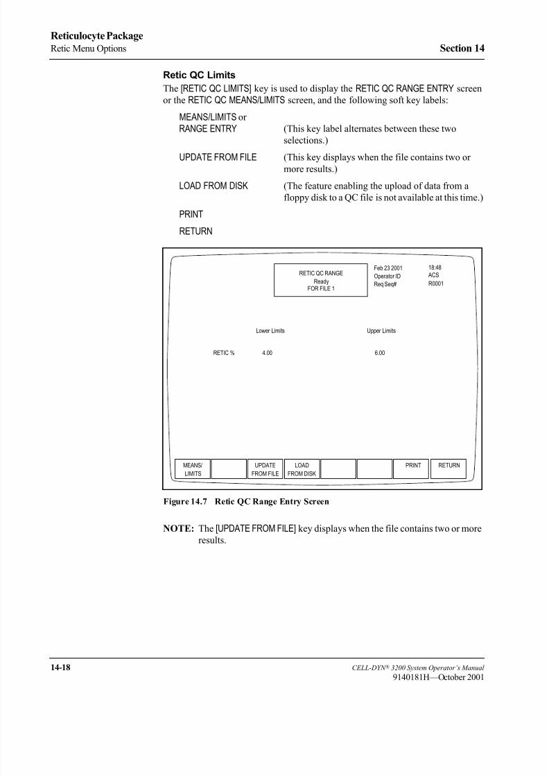
8/21/2019 Equ22-14 CellDyn3200 Op Man
http://slidepdf.com/reader/full/equ22-14-celldyn3200-op-man 610/690
14-18 CELL-DYN ® 3200 System Operator’s Manual
9140181H—October 2001
Reticulocyte Package
Retic Menu Options Section 14
Retic QC Limits
The [RETIC QC LIMITS] key is used to display the RETIC QC RANGE ENTRY screen
or the RETIC QC MEANS/LIMITS screen, and the following soft key labels:
MEANS/LIMITS or
RANGE ENTRY (This key label alternates between these two
selections.)
UPDATE FROM FILE (This key displays when the file contains two or
more results.)
LOAD FROM DISK (The feature enabling the upload of data from a
floppy disk to a QC file is not available at this time.)
RETURN
Figure 14.7 Retic QC Range Entry Screen
NOTE: The [UPDATE FROM FILE] key displays when the file contains two or more
results.
MEANS/
LIMITS
RETIC QC RANGEReady
Feb 23 2001
Operator ID
Req Seq#
18:48
R0001
ACS
UPDATE
FROM FILE
LOAD
FROM DISK
RETURNPRINT
FOR FILE 1
Lower Limits Upper Limits
RETIC % 4.00 6.00

8/21/2019 Equ22-14 CellDyn3200 Op Man
http://slidepdf.com/reader/full/equ22-14-celldyn3200-op-man 611/690
CELL-DYN ® 3200 System Operator’s Manual 14-19
9140181H—October 2001
Section 14 Reticulocyte Package
Figure 14.8 Retic QC Means/Limits Screen
QC Limits are entered by selecting the QC file from the RETIC QC LOG screen (by
moving the cursor to the desired QC file) and pressing the [RETIC QC LIMITS] key.
The RETIC QC MEANS/LIMITS screen is now displayed.
Two types of QC limits are available:
Range Entry This option is used to enter the upper and
lower flagging limits as absolute numbers.
Means and Limits This option is used to enter the mean value
and a + range value that defines the upper
and lower flagging limits.
If Range Entry is selected by pressing the [RANGE ENTRY] key, the current upper
and lower limits for the selected file are displayed as shown in Figure 14.7, Retic
QC Range Entry Screen.
If Means/Limits Entry is selected by pressing the [MEANS/LIMITS] key, the current
means and limits for the selected file are displayed as shown in Figure 14.8, Retic
QC Means/Limits Screen.
RANGE
ENTRY
RETIC QC MEANS/LIMITS
Ready
Feb 23 2001
Operator ID
Req Seq#
18:50
R0001
ACS
UPDATE
FROM FILE
LOAD
FROM DISK
RETURNPRINT
FOR FILE 1
Means Limits (+/-)
RETIC% 5.00 1.00

8/21/2019 Equ22-14 CellDyn3200 Op Man
http://slidepdf.com/reader/full/equ22-14-celldyn3200-op-man 612/690
14-20 CELL-DYN ® 3200 System Operator’s Manual
9140181K—July 2002
Reticulocyte Package
Retic Menu Options Section 14
Procedure: Range Entry
1. Select a file from the RETIC QC LOG screen by using the arrow keys on the
keyboard to move the cursor to the desired file.
2. Press the [RETIC QC LIMITS] key and if necessary press the [RANGE ENTRY] key to display the RETIC QC RANGE ENTRY screen for the selected file.
3. Use the arrow keys on the keyboard to move the cursor to the desired entry
field.
4. Type the desired numbers and press the Enter key on the keyboard to save
each entry.
5. If desired, press the [PRINT] key to obtain a printout of the entered values.
6. Press the [RETURN] key to save the entries and return to the RETIC QC LOGscreen.
NOTE: When entries are saved, the software checks to see if any entries
would result in the upper limit being less than the lower limit. If this
situation occurs, the limits are automatically reversed. The bulletin
line displays the following message:
LIMITS WERE EXCHANGED TO MAKE UPPER > LOWER
Procedure: Means/Limits Entry
1. Select a file from the RETIC QC LOG screen by using the arrow keys on the
keyboard to move the cursor to the desired file.
2. Press the [RETIC QC LIMITS] key and if necessary press the [MEANS/LIMITS] key to display the RETIC QC MEANS/LIMITS entry screen for the selected file.
3. Use the arrow keys on the keyboard to move the cursor to the desired entry
field.
4. Type the desired mean and limit values and press the Enter key on the
keyboard to save each entry.
5. If desired, press the [PRINT] key to obtain a printout of the entered values.
6. Press the [RETURN] key to save the entries and return to the RETIC QC LOG
screen.
QC FILE SETUP
The following soft key labels are displayed on the QC FILE SET UP screen:
LOT NUMBER or REPLICATE ID (This key label alternates between
these two selections.)
TOGGLE ON/OFF
RETURN
The [TOGGLE ON/OFF] key is used to configure the QC file. The file can be used for
commercial controls. The lot number and expiration date may be entered into the
appropriate areas on the QC FILE SET UP screen (see the Figure 14.9) and saved by
pressing the Enter key on the keyboard. The Westgard® Rule selections can be
toggled ON or OFF using the [TOGGLE ON/OFF] key.

8/21/2019 Equ22-14 CellDyn3200 Op Man
http://slidepdf.com/reader/full/equ22-14-celldyn3200-op-man 613/690
CELL-DYN ® 3200 System Operator’s Manual 14-21
9140181H—October 2001
Section 14 Reticulocyte Package
The Westgard® Rules are discussed in detail in Section 11: Quality Control .
Figure 14.9 QC FILE SET UP Screen
Procedure: QC File Set Up
1. Select a file from the RETIC QC LOG screen by using the arrow keys on the
keyboard to move the cursor into the desired file.
2. Press the [QC FILE SET UP] key to display the QC FILE SET UP screen.
3. If necessary press the [LOT NUMBER] key and move the cursor to the <Lot
Number> entry field. Enter the alphanumeric lot number with up to 9
characters. Press the Enter key on the keyboard to save the entry.
4. The cursor will move to the <Expiration Date> entry field. Use the same
format indicated using one or two digits. Separate the digits with a slash (/)
or a period(.). Press the Enter key on the keyboard to save the entry.
5. The cursor will advance to the <WESTGARD RULE SELECTION> entry
fields. Use the arrow keys on the keyboard to position the cursor at the
desired Westgard Rule. Press the [TOGGLE ON/OFF] key to enable or disable
the rule and advance the cursor.
6. Repeat step 5 until all desired rule selections have been made.
7. If desired, press the [PRINT] key to obtain a printout of the entries.
8. Press the [RETURN] key to return to the RETIC QC LOG screen.
9. These steps can be repeated for each QC file you need to set up.
QC FILE SET UP
Ready
Feb 23 2001
Operator ID
Req Seq#
19:00
R0001
ACS
REPLICATE
ID
TOGGLE
ON/OFF
RETURNPRINT
FOR FILE 1
Lot Number: _ _ _ _ _ _ _
Expiration Date (Month/Day/Year): _ _/_ _/_ _
WESTGARD RULE SELECTION:
ON RULE 1:
OFF RULE 2:
ON RULE 3:
OFF RULE 4:
ON RULE 5:
OFF RULE 6:
Value outside 3 SD.
Two consecutive values outside SAME 2 SD.
Two consecutive values outside OPPOSITE 2 SD.
Two of three consecutive values outside SAME 2 SD.
Four consecutive values outside SAME 1 SD.
Ten consecutive values on SAME side of mean.

8/21/2019 Equ22-14 CellDyn3200 Op Man
http://slidepdf.com/reader/full/equ22-14-celldyn3200-op-man 614/690
14-22 CELL-DYN ® 3200 System Operator’s Manual
9140181H—October 2001
Reticulocyte Package
Retic Menu Options Section 14
Operation Set Up Soft Key
Figure 14.10 Operation Set Up Menu Screen with Reticulocyte Package Enabled
The [OPERATION SET UP] key on the RETIC SET UP menu is used to display the
OPERATION SET UP MENU screen. The OPERATION SET UP MENU screen in the
Reticulocyte Package displays the following soft keys:
TURN OFF RETIC PKG
LANGUAGE
SELECT COLOR
BAR CODE SET UP
COMPUTER SET UP
RETURN
The [TURN OFF RETIC PKG] key is discussed earlier in this chapter (in Retic Menu
Options, Turning the Reticulocyte Package ON and OFF ). The [LANGUAGE],[SELECT COLOR], [BAR CODE SET UP] and [COMPUTER SET UP] keys are described
in Section 5: Operating Instructions; Subsection: Set Up Instructions.
TURN OFF
RETIC PKG
OPERATION SET UP MENU
Ready
Feb 23 2001
Operator ID
Req Seq#
19:02
R0001
ACS
LANGUAGE SELECT
COLOR
BAR CODE
SET UP
COMPUTER
SET UP
RETURN

8/21/2019 Equ22-14 CellDyn3200 Op Man
http://slidepdf.com/reader/full/equ22-14-celldyn3200-op-man 615/690
CELL-DYN ® 3200 System Operator’s Manual 14-23
9140181H—October 2001
Section 14 Reticulocyte Package
Units Selection
Figure 14.11 Units Selection Screen
The [UNITS SELECTION] key on the RETIC SET UP screen is used to display the
UNITS SELECTION screen (see Figure 14.11). The UNITS SELECTION screen shows
the report units for the indicated parameters. Units may be selected for each
parameter individually, or a set of units may be selected by pressing the appropriatesoft key. The following soft key labels are displayed on the UNITS SELECTION
screen:
USA UNITS
SI UNITS
SI MOD UNITS
SET1 UNITS
SET2 UNITS
SELECT UNITS
RETURN
USA
UNITS
UNITS SELECTION
Ready
Feb 23 2001
Operator ID
Req Seq#
19:05
R0001
ACS
SI SI MOD
UNITS
SET1
UNITS
SET2
UNITS
RETURN
UNITS
SELECT
UNITS
Parameters
WBC
RBC
HGB
HCT
RDW
PLT
PCT
RETIC ABS
USA SI SI MOD
K/µL
M/µL
g/dL
%
%
K/µL
%
K/µL
SET1
G/L
T/L
g/L
L/L
%CV
G/L
mL/L
G/L
10e9/L
10e12/L
mmol/L
L/L
%CV
10e9/L
mL/L
10e9/L
10e3/µL
10e6/µL
g/L
%
%CV
10e3/L
%
10e3/L
SET2
10e2/µL
10e4/µL
g/dL
%
%
10e4/µL
%
10e4/µL
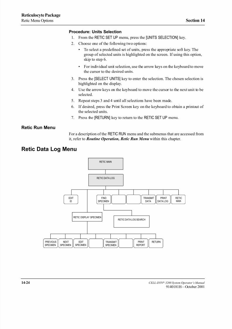
8/21/2019 Equ22-14 CellDyn3200 Op Man
http://slidepdf.com/reader/full/equ22-14-celldyn3200-op-man 616/690
14-24 CELL-DYN ® 3200 System Operator’s Manual
9140181H—October 2001
Reticulocyte Package
Retic Menu Options Section 14
Procedure: Units Selection
1. From the RETIC SET UP menu, press the [UNITS SELECTION] key.
2. Choose one of the following two options:
• To select a predefined set of units, press the appropriate soft key. The
group of selected units is highlighted on the screen. If using this option,
skip to step 6.
• For individual unit selection, use the arrow keys on the keyboard to move
the cursor to the desired units.
3. Press the [SELECT UNITS] key to enter the selection. The chosen selection is
highlighted on the display.
4. Use the arrow keys on the keyboard to move the cursor to the next unit to be
selected.
5. Repeat steps 3 and 4 until all selections have been made.
6. If desired, press the Print Screen key on the keyboard to obtain a printout of
the selected units.
7. Press the [RETURN] key to return to the RETIC SET UP menu.
Retic Run Menu
For a description of the RETIC RUN menu and the submenus that are accessed from
it, refer to Routine Operation, Retic Run Menu within this chapter.
Retic Data Log Menu
RETICEDIT
ID
TRANSMIT
DATA
DATA LOG
FIND
SPECIMEN MAIN
RETIC DISPLAY SPECIMENRETIC DATA LOG SEARCH
PREVIOUS
SPECIMEN
RETURNNEXT
SPECIMEN
REPORT
EDITSPECIMEN SPECIMEN
TRANSMIT
RETIC DATA LOG
RETIC MAIN

8/21/2019 Equ22-14 CellDyn3200 Op Man
http://slidepdf.com/reader/full/equ22-14-celldyn3200-op-man 617/690
CELL-DYN ® 3200 System Operator’s Manual 14-25
9140181H—October 2001
Section 14 Reticulocyte Package
The [RETIC DATA LOG] key on the RETIC MAIN menu screen is used to display the
RETIC DATA LOG screen. The Reticulocyte Data Log stores all data (Reticulocyte
percentage, RBC value, Reticulocyte Absolute Number, and Reticulocyte Flags)
and all patient demographic information in a log format for each of the most current
2,000 Reticulocyte cycles run on the CELL-DYN 3200 System. The record
information is stored chronologically by Reticulocyte Sequence Number. EachReticulocyte Sequence Number will have an “R” prefix (R0 to R1999). This will
distinguish the Reticulocyte Sequence Numbers from the Standard Hematology
Data Log sequence numbers. Scatterplots and histograms are stored for all 2,000
records. The RBC value will be identified on the RETIC DISPLAY SPECIMEN screen
to show whether it was obtained from the Standard Hematology Data Log or
entered by the operator. This section discusses the RETIC DATA LOG screen first,
then it discusses how to review data from the Reticulocyte Data Log.
The current date, time, and operator ID and the last Reticulocyte Sequence Number
that was used are displayed in the upper right-hand corner of the RETIC DATA LOG
screen.
Figure 14.12 Reticulocyte Data Log Screen
NOTE: Use the Left and Right Arrow keys to scroll through the list of parameters
for all specimens displayed on a page. Use the Up and Down Arrow keys
to move the cursor between specimens on a page.
EDIT
ID
RETIC DATA LOG
Ready
Aug 02 2001
Operator ID
Req Seq#
15:20
R0483
TS
DISPLAY FIND
SPECIMEN
RETIC
SPECIMEN
TRANSMIT
DATA
DATA LOG MAIN
1
1
1
1
1
1
1
Patient Name Patient ID Sex Limits
R469
R470
R471
R472
R473
R474
R475
R476
R477
R478
R479R480
R481
R482
Seq Specimen ID
BACKGROUND
PG041-1
PG041-2
A61610
A61610
A61611
A61611
A61612
A61612
A61613
A61613BACKGROUND
D17516
D17516
Seq Specimen ID
Date Time Op
Date Time Op Patient Name Patient ID Sex Limits
O04/16/01 09:17 TS
K04/17/01 06:26 TS
K04/17/01 06:27 TS
O04/17/01 06:28 TS
O04/17/01 06:29 TS
O04/17/01 06:30 TS
O04/17/01 06:31 TS
O04/17/01 06:33 TS
O04/17/01 06:33 TS
O04/17/01 06:34 TS
O04/17/01 06:36 TSO08/02/01 13:42 TS
O08/02/01 13:46 TS
O08/02/01 13:48 TS

8/21/2019 Equ22-14 CellDyn3200 Op Man
http://slidepdf.com/reader/full/equ22-14-celldyn3200-op-man 618/690
14-26 CELL-DYN ® 3200 System Operator’s Manual
9140181H—October 2001
Reticulocyte Package
Retic Menu Options Section 14
Figure 14.13 Reticulocyte Data Log Screen (Parameter Results)
EDIT
ID
RETIC DATA LOG
Ready
Aug 02 2001
Operator ID
Req Seq#
15:25
R0483
TS
DISPLAY FIND
SPECIMEN
RETIC
SPECIMEN
TRANSMIT
DATA
DATA LOG MAIN
R469
R470
R471
R472
R473
R474
R475
R476
R477
R478
R479
R480
R481
R482
Seq Specimen ID
BACKGROUND
PG041-1
PG041-2
A61610
A61610
A61611
A61611
A61612
A61612
A61613
A61613
BACKGROUND
D17516
D17516
Seq Specimen ID
Date Time Op
Date Time Op
1.34
5.84
4.08
4.30
3.92
3.61
9.15
8.49
8.70
9.57
1.63
1.54
2.70
2.70
4.16
4.16
3.51
3.51
2.60
2.60
4.68
4.68
110
116
163
150
321
298
226
249
76
72
0
5
RTC% RBC RABS
RTC% RBC RABS
COUNT
COUNT
O04/16/01 09:17 TS
K04/17/01 06:26 TS
K04/17/01 06:27 TS
O04/17/01 06:28 TS
O04/17/01 06:29 TS
O04/17/01 06:30 TS
O04/17/01 06:31 TS
O04/17/01 06:33 TS
O04/17/01 06:33 TS
O04/17/01 06:34 TS
O04/17/01 06:36 TS
O08/02/01 13:42 TS
O08/02/01 13:46 TS
O08/02/01 13:48 TS

8/21/2019 Equ22-14 CellDyn3200 Op Man
http://slidepdf.com/reader/full/equ22-14-celldyn3200-op-man 619/690
CELL-DYN ® 3200 System Operator’s Manual 14-27
9140181M—June 2004
Section 14 Reticulocyte Package
Retic Data Log Codes
The following letters are displayed on the RETIC DATA LOG screen in the column
immediately preceding the date. (See the preceding figure.)
O Sample was run in the Open Mode.
K Flow Error or Fragile RBCs.
NOTE: Reticulocyte results are not suppressed for Fragile RBCs but are
suppressed for Flow Errors.
The RETIC DATA LOG screen contains the following soft keys:
EDIT ID (This key label displays only when the cursor is positioned
next to a patient record.)
DISPLAY SPECIMEN
FIND SPECIMEN
TRANSMIT DATA
PRINT DATA LOG
RETIC MAIN
Edit ID
The [EDIT ID] key on the RETIC DATA LOG screen is used to edit only the Specimen
ID. When the [EDIT ID] key is pressed, the cursor moves into the <SPECIMEN ID>
field and all soft key labels are blank. Each edit is saved by pressing the Enter key
on the keyboard.
When using the Edit Specimen ID feature in the Data Log, set up a laboratory
procedure to verify any Specimen ID that has been manually edited in the Data Log
by showing the content of the Specimen ID before and after editing.Such verification could be:
Printouts of the Data Log summary reports that show the edited ID. These printouts
should be signed, dated and saved to ensure tracking of any changes to specimen
identification within your laboratory.
OR
Re-running any specimen unintentionally identified with a Rack and Tube Number,
via Open or Closed Mode, to confirm that the correct Specimen ID is applied.
NOTE: The [EDIT ID] key displays only when the cursor is positioned next to a
Reticulocyte Patient Record. It is not displayed for Reticulocyte
Background or Reticulocyte QC records.
The current date, time, and operator ID and the last Reticulocyte Sequence Number
that was used are displayed in the upper right-hand corner.
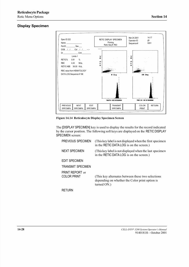
8/21/2019 Equ22-14 CellDyn3200 Op Man
http://slidepdf.com/reader/full/equ22-14-celldyn3200-op-man 620/690
14-28 CELL-DYN ® 3200 System Operator’s Manual
9140181H—October 2001
Reticulocyte Package
Retic Menu Options Section 14
Display Specimen
Figure 14.14 Reticulocyte Display Specimen Screen
The [DISPLAY SPECIMEN] key is used to display the results for the record indicated
by the cursor position. The following soft keys are displayed on the RETIC DISPLAYSPECIMEN screen:
PREVIOUS SPECIMEN (This key label is not displayed when the first specimenin the RETIC DATA LOG is on the screen.)
NEXT SPECIMEN (This key label is not displayed when the last specimen
in the RETIC DATA LOG is on the screen.)
EDIT SPECIMEN
TRANSMIT SPECIMEN
PRINT REPORT or
COLOR PRINT (This key alternates between these two selections
depending on whether the Color print option is
turned ON.)
RETURN
PREVIOUS
SPECIMEN
RETIC DISPLAY SPECIMEN
Priming
Mar 24 2001
Operator ID
Sequence #
14:17
0201
gh
NEXT EDIT
SPECIMEN
TRANSMIT
SPECIMEN
RETURN
SPECIMEN
COLOR
Spec ID 222
Name ________________
Pat ID _________ Sex ___DOB __/__/____ Col __/__/____ --:--
Dr _______________ Cmt _________
Limits 1
RETIC% 0.81 %
RBC 4.43 M/uL
RETIC ABS 36.00 K/uL
RBC value from HEMATOLOGY
DATA LOG Sequence # 198
Retic Seq #: R63
8/21/2019 Equ22-14 CellDyn3200 Op Man
http://slidepdf.com/reader/full/equ22-14-celldyn3200-op-man 621/690
CELL-DYN ® 3200 System Operator’s Manual 14-29
9140181M—June 2004
Section 14 Reticulocyte Package
Previous Specimen
The [PREVIOUS SPECIMEN] key is used to display the results for the Reticulocyte
Sequence Number preceding the one currently displayed without returning to the
RETIC DATA LOG screen.
Next SpecimenThe [NEXT SPECIMEN] key is used to display the results for the Reticulocyte
Sequence Number following the one currently displayed without returning to the
RETIC DATA LOG screen.
Edit Specimen
The [EDIT SPECIMEN] key is used to edit patient demographic information for the
selected record. It may also be used to edit and display the results with a Parameter
Set or Patient Limit Set different from the one currently displayed. The following
soft key labels are displayed when the [EDIT SPECIMEN] key is pressed:
CONFIRM
CANCEL
These keys are used to [CONFIRM] or [CANCEL] the edits. The bulletin line displays
the message PRESS CONFIRM TO SAVE CHANGES OR CANCEL TO
CANCEL CHANGES. When the [CONFIRM] key is pressed, the edited record is
displayed.
Transmit Specimen
The [TRANSMIT SPECIMEN] key is used to transmit the displayed report to a
Laboratory Information System or on-line computer.
Print Report/Color Print
The [PRINT REPORT] key is used to print a graphics report for the displayed results.
The [COLOR PRINT] key displays if the Color Print option is turned on in the SET
UP MENU.
NOTE: The ticket printer is not supported in the Reticulocyte Mode.
Return
The [RETURN] key is used to return to the RETIC DATA LOG screen.
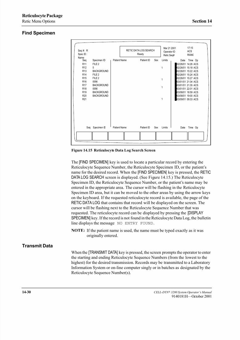
8/21/2019 Equ22-14 CellDyn3200 Op Man
http://slidepdf.com/reader/full/equ22-14-celldyn3200-op-man 622/690
14-30 CELL-DYN ® 3200 System Operator’s Manual
9140181H—October 2001
Reticulocyte Package
Retic Menu Options Section 14
Find Specimen
Figure 14.15 Reticulocyte Data Log Search Screen
The [FIND SPECIMEN] key is used to locate a particular record by entering the
Reticulocyte Sequence Number, the Reticulocyte Specimen ID, or the patient’s
name for the desired record. When the [FIND SPECIMEN] key is pressed, the RETIC
DATA LOG SEARCH screen is displayed. (See Figure 14.15.) The ReticulocyteSpecimen ID, the Reticulocyte Sequence Number, or the patient’s name may be
entered in the appropriate area. The cursor will be flashing in the Reticulocyte
Specimen ID area, but it can be moved to the other areas by using the arrow keys
on the keyboard. If the requested reticulocyte record is available, the page of the
RETIC DATA LOG that contains that record will be displayed on the screen. The
cursor will be flashing next to the Reticulocyte Sequence Number that was
requested. The reticulocyte record can be displayed by pressing the [DISPLAYSPECIMEN] key. If the record is not found in the Reticulocyte Data Log, the bulletin
line displays the message NO ENTRY FOUND.
NOTE: If the patient name is used, the name must be typed exactly as it was
originally entered.
Transmit Data
When the [TRANSMIT DATA] key is pressed, the screen prompts the operator to enter
the starting and ending Reticulocyte Sequence Numbers (from the lowest to the
highest) for the desired transmission. Records may be transmitted to a Laboratory
Information System or on-line computer singly or in batches as designated by the
Reticulocyte Sequence Number(s).
RETIC DATA LOG SEARCH
Ready
Mar 21 2001
Operator ID
Retic Seq#
17:15
R0060
ACSSeq # : R
Spec ID :
Name :
1
1
1
1
R11
R12
R13
R14
R15
R16
R17
R18
R19
R20
R21
Seq Specimen ID
FILE 2
5
BACKGROUND
FILE 2
FILE 2
0056
BACKGROUND
0056
BACKGROUND
BACKGROUND
Seq Specimen ID Date Time Op
Patient Name Patient ID Sex Limits
Patient Name Patient ID Sex Limits
Date Time Op
O02/26/01 14:26 ACS
O02/26/01 15:18 ACS
O02/26/01 15:22 ACS
O02/26/01 15:24 ACS
O02/26/01 15:27 ACS
O03/01/01 21:34 ACS
O03/01/01 21:35 ACS
O03/01/01 22:01 ACS
O03/08/01 18:59 ACS
O03/08/01 19:00 ACS
O03/09/01 09:33 ACS
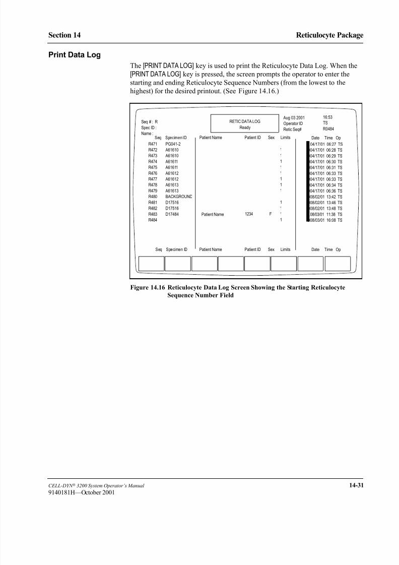
8/21/2019 Equ22-14 CellDyn3200 Op Man
http://slidepdf.com/reader/full/equ22-14-celldyn3200-op-man 623/690
CELL-DYN ® 3200 System Operator’s Manual 14-31
9140181H—October 2001
Section 14 Reticulocyte Package
Print Data Log
The [PRINT DATA LOG] key is used to print the Reticulocyte Data Log. When the
[PRINT DATA LOG] key is pressed, the screen prompts the operator to enter the
starting and ending Reticulocyte Sequence Numbers (from the lowest to the
highest) for the desired printout. (See Figure 14.16.)
Figure 14.16 Reticulocyte Data Log Screen Showing the Starting Reticulocyte
Sequence Number Field
RETIC DATA LOG
Ready
Aug 03 2001
Operator ID
Retic Seq#
16:53
R0484
TSSeq # : R
Spec ID :
Name :
Patient Name F
1
1
1
1
1
1
1
1
1
1
1
1
1234
R471
R472
R473
R474
R475
R476
R477
R478
R479
R480R481
R482
R483
R484
Seq Specimen ID
PG041-2
A61610
A61610
A61611
A61611
A61612
A61612
A61613
A61613
BACKGROUNDD17516
D17516
D17484
Seq Specimen ID Date Time Op
Patient Name Patient ID Sex Limits
Patient Name Patient ID Sex Limits
Date Time Op
K 04/17/01 06:27 TS
O04/17/01 06:28 TS
O04/17/01 06:29 TS
O04/17/01 06:30 TS
O04/17/01 06:31 TS
O04/17/01 06:33 TS
O04/17/01 06:33 TS
O04/17/01 06:34 TS
O04/17/01 06:36 TS
O08/02/01 13:42 TSO08/02/01 13:46 TS
O08/02/01 13:48 TS
K08/03/01 11:38 TS
O08/03/01 16:08 TS

8/21/2019 Equ22-14 CellDyn3200 Op Man
http://slidepdf.com/reader/full/equ22-14-celldyn3200-op-man 624/690
14-32 CELL-DYN ® 3200 System Operator’s Manual
9140181H—October 2001
Reticulocyte Package
Retic Menu Options Section 14
Data Review from the Retic Data Log
Scrolling Through the Retic Data Log
The Page Up and Page Down keys on the keyboard can be used to scroll rapidly
through the records stored in the Reticulocyte Data Log. Press the Page Up key to
scroll backward and press the Page Down key to scroll forward.
Displaying a Record
A copy of the RETIC RUN RESULT screen can be displayed for the most current
2,000 records in the Reticulocyte Data Log. A record is displayed by positioning
the cursor at the record you desire in the Reticulocyte Data Log listing and pressing
the [DISPLAY SPECIMEN] key. The Status Box indicates RETIC DISPLAY SPECIMEN
on results displayed (or printed) from the Reticulocyte Data Log record. (See
Figure 14.17.)
Figure 14.17 Reticulocyte Display Specimen Screen
PREVIOUS
SPECIMEN
RETIC DISPLAY SPECIMEN
Ready
Aug 02 2001Operator ID
Retic Seq#
15:31
R0483
TS
EDIT
SPECIMEN
TRANSMIT
SPECIMEN
RETURNCOLOR
Spec ID D17516
Name ________________
Pat ID _________ Sex ___
DOB __/__/____ Col __/__/____ --:--
Dr _______________ Cmt _________
Limits 1
RETIC% 1.54 %
RBC 4.68 M/uL
RETIC ABS 72.00 K/uL
RBC value from HEMATOLOGY
DATA LOG Sequence # 8842
Retic Seq # R482

8/21/2019 Equ22-14 CellDyn3200 Op Man
http://slidepdf.com/reader/full/equ22-14-celldyn3200-op-man 625/690
CELL-DYN ® 3200 System Operator’s Manual 14-33
9140181H—October 2001
Section 14 Reticulocyte Package
Procedure: Displaying a Record
1. From the RETIC MAIN menu screen press the [RETIC DATA LOG] key.
2. If the desired record is not displayed on the screen, press the [FIND SPECIMEN] key to display the RETIC DATA LOG SEARCH screen.
3. To start the search, type the Reticulocyte Specimen ID, the Reticulocyte
Sequence Number, or the patient name, then press the Enter key on the
keyboard.
NOTE: If the patient name is used, the name must be typed exactly as it was
originally entered.
NOTE: If necessary, you may press the Escape key (ESC) or the Enter key
on the keyboard to exit from the search function and return to the
RETIC DATA LOG screen.
4. If the requested record is available, the screen displays the page of the
Reticulocyte Data Log with the cursor flashing at the Reticulocyte Sequence
Number of the record.
5. Press the [DISPLAY SPECIMEN] key to display the RETIC DISPLAY SPECIMEN screen for the selected record.
6. Press the [PRINT REPORT] key (or the [COLOR PRINT] key if it is displayed) to
obtain a printout.
7. The [PREVIOUS SPECIMEN] or [NEXT SPECIMEN] key may now be used to
display records listed in the Reticulocyte Data Log that are next to the one
currently displayed.
Retic QC Menu
RETIC QC
RETICVIEW
QC LOG
RETIC QC
LIMITS MAINQC FILE
SET UP
RETURNPURGE
QC LOG
QC LOG
LEVEY-
JENNINGS
MOVE
SPECIMEN
REJECT
SPECIMENDELETE
SPECIMEN
PRINT RETURN
ACCEPT
SPECIMEN
RETIC MAIN

8/21/2019 Equ22-14 CellDyn3200 Op Man
http://slidepdf.com/reader/full/equ22-14-celldyn3200-op-man 626/690
14-34 CELL-DYN ® 3200 System Operator’s Manual
9140181H—October 2001
Reticulocyte Package
Retic Menu Options Section 14
Figure 14.18 Reticulocyte QC Log Screen
The [RETIC QC] key on the RETIC MAIN menu screen is used to display the RETICQC LOG screen. The Reticulocyte Package on the CELL-DYN 3200 System offers
six QC Logs with statistical and graphical analysis of the data. The statistical
analysis includes the mean, standard deviation, and coefficient of variation. The
results in each QC Log can be displayed as a Levey-Jennings chart. Westgard®
Rules can be applied to each QC Log. The rule options can be used independently
or in combination, at the operator’s discretion.
NOTE: The [RETIC QC LIMITS] key and the [QC FILE SET UP] key are used to set
up the QC files.
The following soft keys are displayed on the RETIC QC LOG screen:
VIEW QC LOG (Move the cursor with the arrow keys on the keyboard
to the QC file desired, then press this soft key.)
RETIC QC LIMITS
QC FILE SET UP
RETIC MAIN
VIEW
QC LOG
RETIC QC LOG
Ready
Feb 23 2001
Operator ID
Req Seq#
19:10
R0001
ACS
RETIC QC QC FILE
SET UP
RETIC
LIMITS
1.
2.
3.
4.
5.
6.
File Name
Select a QC file with the arrow keys or enter a new file name.
FILE 1
FILE 2
FILE 3
FILE 4
FILE 5
FILE 6
0
0
0
0
0
0
# Specimens
MAIN

8/21/2019 Equ22-14 CellDyn3200 Op Man
http://slidepdf.com/reader/full/equ22-14-celldyn3200-op-man 627/690
CELL-DYN ® 3200 System Operator’s Manual 14-35
9140181H—October 2001
Section 14 Reticulocyte Package
View QC Log
Figure 14.19 View Reticulocyte QC Log Screen
The [VIEW QC LOG] key is used to display the QC Log indicated by the position of the
cursor. Each QC Log display includes the following information (see Figure 14.19):
1. The lot number and expiration date are displayed in the upper left corner. The
file name, the number of runs currently in the file, and the file capacity arealso in the upper left corner. (For example, 35/120 indicates that the file
contains 35 runs out of a possible 120.) The page number of the display and
the total number of pages in the file are also displayed in the upper left corner.
2. The current date, time, and operator ID and the last Reticulocyte Sequence
Number to be used are all displayed in the upper right-hand corner.
3. The remainder of the screen displays the file information and the data. The Upper
and Lower Limits and Target Mean entered are displayed immediately above
each parameter name. The Reticulocyte Sequence Number for each result is
displayed to the left of the data. The date, time, and operator ID when the
reticulocyte sample was run are displayed to the right of the data.
4. The following QC Log codes are displayed in the column immediately preceding the date. These codes are the same as those used in the
Reticulocyte Data Log.
O Sample was run in the Open Mode.
K Flow Error or Fragile RBCs.
NOTE: Reticulocyte results are not suppressed for Fragile RBCs but are
suppressed for Flow Errors.
PURGE
QC LOG
VIEW RETIC QC LOG
Ready
Aug 02 2001
Operator ID
Retic Seq#
15:51
R0483
TS
LEVEY- REJECT
SPECIMEN
DELETE
SPECIMEN
MOVE
SPECIMEN
RETURN
JENNINGS
QC LOG
Lot Number : PG041-1Exp. Date: 05/31/01PG041-1: 15/120
Page 2 of 21.90
0.30
1.10
RTC%
1.28
1.26
1.34
RTC%
15
1.26
0.09
7.0
Upper Limits:
Lower Limits:
Target Mean:
Seq
R433
R451
R470
N:
File Mean
Std Dev:
CV(%):
DATE TIME Op
K04/12/0106:21 TS
K04/16/0106:58 TS
K04/17/0106:26 TS

8/21/2019 Equ22-14 CellDyn3200 Op Man
http://slidepdf.com/reader/full/equ22-14-celldyn3200-op-man 628/690
14-36 CELL-DYN ® 3200 System Operator’s Manual
9140181H—October 2001
Reticulocyte Package
Retic Menu Options Section 14
5. The statistics are displayed below the data as follows:
N: The number of runs used in the calculation.
FILE MEAN: The mean value for the number of runs used in the
calculation.
Std Dev: The standard deviation for the number of runs used in thecalculation.
CV%: The coefficient of variation, in percent, for the number of
runs used in the calculation.
The following soft keys are displayed on the VIEW RETIC QC LOG screen:
PURGE QC LOG
LEVEY-JENNINGS
REJECT SPECIMEN or
ACCEPT SPECIMEN (This key label alternates between these two
selections when the soft key is pressed.)
DELETE SPECIMEN
MOVE SPECIMEN
PRINT QC LOG
RETURN
These soft keys are discussed in the order in which they appear on the screen from
left to right.
Purge QC Log Soft Key
The [PURGE QC LOG] key is used to delete the contents of a designated file in the
QC Log. When the [PURGE QC LOG] key is pressed, the following soft key labelsare displayed:
CONFIRM PURGE
CANCEL PURGE
These soft keys are used to confirm or cancel the [PURGE QC LOG] command.
When the [CONFIRM PURGE] key is pressed, all the results are deleted from the
designated file (the data are no longer displayed nor stored in the file). When the [CANCEL PURGE] key is pressed, the results are not deleted.

8/21/2019 Equ22-14 CellDyn3200 Op Man
http://slidepdf.com/reader/full/equ22-14-celldyn3200-op-man 629/690
CELL-DYN ® 3200 System Operator’s Manual 14-37
9140181H—October 2001
Section 14 Reticulocyte Package
Levey-Jennings
Figure 14.20 The Reticulocyte Levey-Jennings Screen
The [LEVEY-JENNINGS] key is used to display the Levey-Jennings graphs of the
data in the QC Log. (See the preceding figure.) Up to 30 data points can be
displayed on the screen at one time. If there are more than 30 data points in the QC
Log, the [PREVIOUS 10] and [NEXT 10] keys can be used to scroll through the graphs.The following soft key labels are displayed when the [LEVEY-JENNINGS] key is
pressed:
PREVIOUS 10 (This key is not displayed when the first 10 data
points are displayed.)
NEXT 10 (This key is not displayed when the last 10 data
points are displayed.)
RETURN
The [PRINT] key is used to print the Levey-Jennings graphs.
The [RETURN] key is used to return to the VIEW RETIC QC LOG screen.
RETIC LEVEY-JENNINGS
Ready
Mar 21 2001
Operator ID
Retic Seq#
17:16
R0060
ACS
PREVIOUS
10
NEXT
10
RETURNPRINT
QC File: FILE 1Seq num: R7 TO R50
WESTGARD RULE WARNINGS

8/21/2019 Equ22-14 CellDyn3200 Op Man
http://slidepdf.com/reader/full/equ22-14-celldyn3200-op-man 630/690
14-38 CELL-DYN ® 3200 System Operator’s Manual
9140181H—October 2001
Reticulocyte Package
Retic Menu Options Section 14
Reject Specimen/Accept Specimen
Figure 14.21 View Reticulocyte QC Log Screen with Rejected Results
The [REJECT SPECIMEN] key is used to exclude the results from statistical
calculations for the specimen indicated by the cursor position. (See Figure 14.21.)
When the soft key is pressed, the key label changes to [ACCEPT SPECIMEN], an “R”
is displayed in the column immediately left of the results, and the statistics arerecalculated excluding those results. The data are still displayed and stored in the
file, but they are excluded from the statistical calculations.
When the [ACCEPT SPECIMEN] key is pressed, the “R” is deleted and the statistics
are recalculated to include those results.
Delete Specimen
The [DELETE SPECIMEN] key is used to delete the results for the specimen indicated
by the cursor position. When the [DELETE SPECIMEN] key is pressed, the following
soft key labels are displayed:
CONFIRM DELETION
CANCEL DELETION
These soft keys are used to confirm or cancel the Delete Specimen command.
When the [CONFIRM DELETION] key is pressed, the results are deleted from the file
(the data are no longer displayed nor stored in the file and cannot be recorded) and
the statistics are recalculated excluding those results. When the [CANCELDELETION] key is pressed, the delete specimen operation is cancelled.
PURGE
QC LOG
VIEW RETIC QC LOG
Ready
Aug 02 2001
Operator ID
Retic Seq#
14:22
R0482
TS
LEVEY- ACCEPT
SPECIMEN
DELETE
SPECIMEN
MOVE
SPECIMEN
RETURN
JENNINGS
QC LOG
Lot Number: PG041-1Exp. Date: 05/31/01PG041-1: 15/120
Page 2 of 2
Upper Limits:
Lower Limits:
Target Mean:
Seq
R433
R451
R470 R
N:
FILE MEAN
Std Dev:
CV (%):
1.90
0.30
1.10
RTC%
1.28
1.26
1.34
RTC%
14
1.26
0.09
7.0
DATE TIME Op
K04/12/0106:21 TS
K04/16/0106:58 TS
K04/17/0106:26 TS

8/21/2019 Equ22-14 CellDyn3200 Op Man
http://slidepdf.com/reader/full/equ22-14-celldyn3200-op-man 631/690
CELL-DYN ® 3200 System Operator’s Manual 14-39
9140181H—October 2001
Section 14 Reticulocyte Package
Move Specimen
The [MOVE SPECIMEN] key is used to move a QC result located in one file
(indicated by the cursor position) to another QC file. When the [MOVE SPECIMEN] key is pressed, the RETIC QC LOG screen is displayed, allowing the desired file to
be selected. When the [MOVE TO FILE] key is pressed, the result is moved to the
indicated file.
Procedure: Move Specimen
1. From the RETIC QC LOG screen, use the arrow keys on the keyboard to move
the cursor to the file containing the result to be moved.
2. Press the [VIEW QC LOG] key.
3. Use the arrow keys on the keyboard to position the cursor at the result that is
to be moved.
4. Press the [MOVE SPECIMEN] key to display the VIEW RETIC QC LOG menu.
5. Use the arrow keys on the keyboard to move the cursor to the file in which
the results are to be placed.
6. Press the [MOVE TO FILE] key to move the results to the designated file.
NOTE: The results are moved to the end of the list of data that is currently
in the file. The placement of results in the list of data will determine
their location on the Levey-Jennings graph.
7. The VIEW RETIC QC LOG screen for the original file is displayed showing that
results have been moved.
Print QC Log
The [PRINT QC LOG] key is used to print the entire QC Log.
ReturnThe [RETURN] key is used to return to the RETIC QC LOG screen.
Retic Diagnostics Menu
DIAGNOSTICS MENU
RETICFAULTREPORT
RETICRAW DATA MAIN
CLEAR
FAULTS
PRINT RETURNRETIC
CNT GRAPH
RETIC
CNT RATE
RETICCNT RATE
CD3200 RETIC MENU
PRINT RETURN
EXECUTION
TIMES
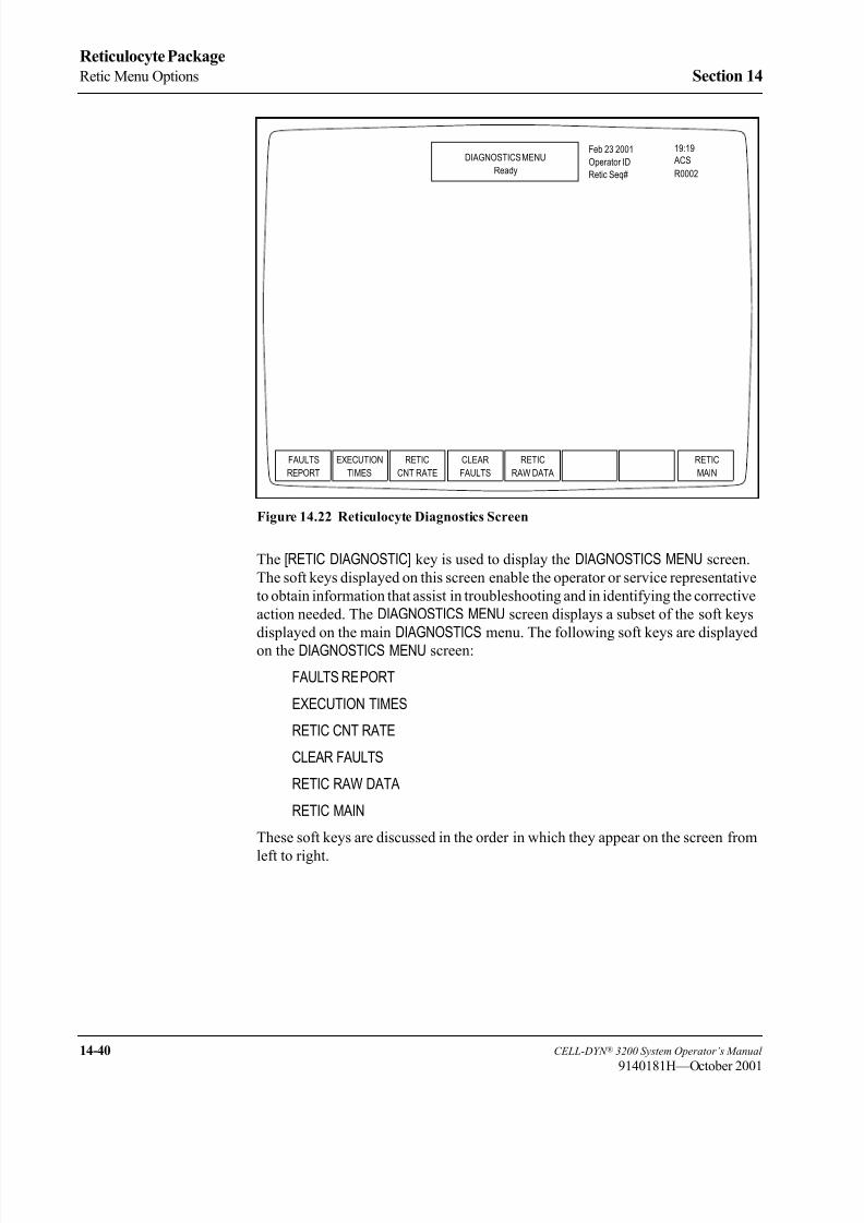
8/21/2019 Equ22-14 CellDyn3200 Op Man
http://slidepdf.com/reader/full/equ22-14-celldyn3200-op-man 632/690
14-40 CELL-DYN ® 3200 System Operator’s Manual
9140181H—October 2001
Reticulocyte Package
Retic Menu Options Section 14
Figure 14.22 Reticulocyte Diagnostics Screen
The [RETIC DIAGNOSTIC] key is used to display the DIAGNOSTICS MENU screen.
The soft keys displayed on this screen enable the operator or service representative
to obtain information that assist in troubleshooting and in identifying the corrective
action needed. The DIAGNOSTICS MENU screen displays a subset of the soft keys
displayed on the main DIAGNOSTICS menu. The following soft keys are displayed
on the DIAGNOSTICS MENU screen:
FAULTS REPORT
EXECUTION TIMES
RETIC CNT RATE
CLEAR FAULTS
RETIC RAW DATA
RETIC MAIN
These soft keys are discussed in the order in which they appear on the screen from
left to right.
FAULTS
REPORT
DIAGNOSTICS MENU
Ready
Feb 23 2001
Operator ID
Retic Seq#
19:19
R0002
ACS
EXECUTION RETIC
CNT RATE
CLEAR
FAULTS
RETIC
RAW DATA
RETIC
TIMES MAIN

8/21/2019 Equ22-14 CellDyn3200 Op Man
http://slidepdf.com/reader/full/equ22-14-celldyn3200-op-man 633/690
CELL-DYN ® 3200 System Operator’s Manual 14-41
9140181L—July 2003
Section 14 Reticulocyte Package
Fault Report
When the [FAULTS REPORT] key is pressed, information regarding any pending
fault is displayed on the screen. The screen displays the words OPERATOR
CORRECTABLE FAULT REPORT: or FATAL FAULT REPORT and any
additional information available. If there is no fault, the screen displays the words
NO FAULT PENDING. Operator-correctable faults (for example, Waste Full,Diluent Empty) can be cleared after the corrective action has been taken by
pressing the [CLEAR FAULT] key.
Execution Times
Display the time in tics used for various cycles during routine function of the
system.
NOTE: A tic is an integer that equals 0.055 seconds.
Retic Count Rate
Figure 14.23 Reticulocyte Count Rate Screen (Tabular Format)
When the [RETIC CNT RATE] key is pressed followed by [RETIC CNT DATA], thefollowing soft key labels are displayed:
RETIC CNT GRAPH
RETURN
RETIC
CNT GRAPH
DIAGNOSTICS MENU
Ready
Aug 02 2001
Operator ID
Retic Seq#
14:32
R0482
TS
RETURNPRINT
RETIC: TOTAL COUNT: 31693
TIME: 0.50 1.00 1.50 2.00 2.50 3.00 3.50 4.01
COUNT: 2181 4204 6348 8458 10517 12705 14832 16936
RATE: 4362.00 4046.00 4288.00 4220.00 4118.00 4376.00 4254.00 4166.34
TIME: 4.51 5.01 5.51 6.02 6.52 7.02 7.50
COUNT: 19161 21247 23395 25507 27596 29692 31693
RATE: 4405.94 4172.00 4296.00 4182.18 4178.00 4192.00 4125.77

8/21/2019 Equ22-14 CellDyn3200 Op Man
http://slidepdf.com/reader/full/equ22-14-celldyn3200-op-man 634/690
14-42 CELL-DYN ® 3200 System Operator’s Manual
9140181H—October 2001
Reticulocyte Package
Retic Menu Options Section 14
The data displayed on the screen are the kinetic data for the Reticulocyte specimen
from the last run, displayed in a tabular format. (See Figure 14.23.) The total count,
data acquisition intervals, and rate per second are displayed.
NOTE: Time is displayed on the X-axis. Raw count is displayed on the Y-axis.
When the [RETIC CNT GRAPH] key is pressed, the rate per second data are displayedas a graph. (See the following figure.) The kinetic data and graph information are
useful when troubleshooting problems with the reticulocyte parameter. A printout
of the Reticulocyte Count Rate may be obtained by pressing the [PRINT] key when
the desired format is displayed on the screen.
Figure 14.24 Reticulocyte Count Rate Screen (Graphic Format)
Clear Faults
When the [CLEAR FAULTS] key is pressed, the Analyzer returns to the READY state
if the corrective action that was taken has resolved the problem. If the corrective
action did not correct the problem, the fault status does not change.
NOTE: Only operator-correctable faults can be cleared with the [CLEAR FAULTS]
key.
RETIC
CNT DATA
DIAGNOSTICS MENU
Ready
Aug 02 2001
Operator ID
Retic Seq#
14:32
R0482
TS
RETURNPRINT
4405.9
0 0.5 1.0 1.5 2.0 2.5 3.0 3.5 4.0 4.5 5.0 5.5 6.0 6.5 7.0 7.5
RETIC CNT GRAPH
3855.2
3304.5
2753.7
2203.0
1652.2
1101.5
550.7

8/21/2019 Equ22-14 CellDyn3200 Op Man
http://slidepdf.com/reader/full/equ22-14-celldyn3200-op-man 635/690
CELL-DYN ® 3200 System Operator’s Manual 14-43
9140181H—October 2001
Section 14 Reticulocyte Package
Retic Raw Data
Figure 14.25 Reticulocyte Raw Data Screen
When the [RETIC RAW DATA] key is pressed, information pertaining to the last cycle
run in the Reticulocyte Package is displayed.
PrintWhen a DIAGNOSTICS option is selected, a [PRINT] key displays.
When the [PRINT] key is pressed, a Diagnostics Report is printed. This report
contains information pertinent to the data displayed on the screen at the time the
key is pressed. If no data are displayed on the screen, the printed report contains
the current fault status.
Retic Main
The [RETIC MAIN] key is used to return to the RETIC MAIN menu screen. The [RETIC
MAIN] key appears on most primary RETIC DIAGNOSTICS screen and works the
same way on each screen.
FAULTS
REPORT
DIAGNOSTICS MENU
Ready
Feb 23 2001
Operator ID
Retic Seq#
19:24
R0002
ACS
EXECUTION RETIC
CNT RATE
CLEAR
FAULTS
RAW DATA
SUMMARY
RETIC
TIMES
MAIN
List Mode RETIC: 1 RBC: 0 PLT: 0 NOC: 0 LRBC: 0
Raw Count RETIC: 1 RBC/PLT: 0 NOC: 0
HGB Sample 1: 1462 2: 1461 3: 1461 4: 1462 5: 1461
HGB Ref 1462 1461 1461 1461 1461
WBC Alg % Tot: 98%
RBC Alg Lo thr: 51
PLT Alg Adj cnt: 0 Lo thr: 35 Hi thu: 195

8/21/2019 Equ22-14 CellDyn3200 Op Man
http://slidepdf.com/reader/full/equ22-14-celldyn3200-op-man 636/690
14-44 CELL-DYN ® 3200 System Operator’s Manual
9140181H—October 2001
Reticulocyte Package
Retic Menu Options Section 14
Retic Special Protocols Menu
The [RETIC SP PROTOCOLS] key is used to display the SPECIAL PROTOCOLS
menu. The following soft key labels are displayed on the SPECIAL PROTOCOLS
menu:
REAGENT RESERVOIR
EMPTY/FILL FLOW CELL
CLEAN/RES SHEAR VALVE
DISABLE/ENAB ANALYZER
RETIC MAIN
A brief description of the function of each soft key follows. Instructions for the
detailed use of each function are given in the appropriate maintenance procedure
in Section 9: Service and Maintenance.
Figure 14.26 Reticulocyte Special Protocols Screen
SPECIAL PROTOCOLS
RETICDISAB/ENAB
ANALYZER
CLEAN/RES
SHEAR VALVE MAINEMPTY/FILL
FLOW CELL
CD3200 RETIC MAIN MENU
REAGENT
RESERVOIR
SPECIAL PROTOCOLSReady
Feb 23 2001
Operator ID
Retic Seq#
19:27
R0002 ACS
REAGENT EMPTY/FILL
FLOW CELL
CLEAN/RES
SHEAR VALVE
RETIC
RESERVOIR
DISAB/ENAB
ANALYZER MAIN

8/21/2019 Equ22-14 CellDyn3200 Op Man
http://slidepdf.com/reader/full/equ22-14-celldyn3200-op-man 637/690
CELL-DYN ® 3200 System Operator’s Manual 14-45
9140181H—October 2001
Section 14 Reticulocyte Package
Reagent Reservoir
The [REAGENT RESERVOIR] key is used to select the reagent reservoirs for
emptying and filling. When the [REAGENT RESERVOIR] key is pressed, the
following soft key labels are displayed.
RETURN
The screen displays instructions for draining and filling the reagent reservoir.
EMPTY/FILL DIL/SHEATH
When the [EMPTY DIL/SHEATH] key is pressed, the diluent and sheath reservoirs are
drained and the key toggles to [FILL DIL/SHEATH]. When the [FILL DIL/SHEATH] key
is pressed, the diluent and sheath reservoirs are refilled.
EMPTY/FILL HGB LYSE
When the [EMPTY HGB LYSE] key is pressed, the HGB lyse supply tubing is drained
and the key toggles to [FILL HGB LYSE]. When the [FILL HGB LYSE] key is pressed,
the HGB lyse supply tubing is refilled.
EMPTY/FILL WBC LYSE
When the [EMPTY WBC LYSE] key is pressed, the WBC lyse supply tubing is drained
and the key toggles to [FILL WBC LYSE]. When the [FILL WBC LYSE] key is pressed,
the WBC lyse supply tubing is refilled.
Empty/Fill Flow Cell
NOTE: This procedure is performed only in the Open Mode. If necessary, press
[CHANGE SAMPLER] in the RUN screen to select Open Mode.
Pressing the [EMPTY/FILL FLOW CELL] key displays a submenu showing the [EMPTY
FLOW CELL] and [RETURN] keys.When the [EMPTY FLOW CELL] key is pressed, diluent/sheath in the Optical Flow
Cell is drained and the key toggles to [FILL FLOW CELL] upon completion.
When the [FILL FLOW CELL] key is pressed, the flow cell is refilled with diluent/
sheath.
Clean/Restore Shear Valve
The [CLEAN/RES SHEAR VALVE] key is used to prepare the shear valve for cleaning.
Pressing the [CLEAN/RES SHEAR VALVE] key displays a submenu showing the
[CLEAN/RES SHEAR VALVE] and [RETURN] keys.
When the [CLEAN/RES SHEAR VALVE] key is pressed, the System partially emptiesthe syringes, flushing the reagents out of the shear valve and associated tubing. The
shear valve then rotates into the position necessary for its removal. After the shear
valve rotates back to its operational position [RESTORE SHEAR VALVE].
When the [RESTORE SHEAR VALVE] key is pressed, the syringes refill the shear
valve and the associated tubing, and the shear valve rotates back to its operational
position.

8/21/2019 Equ22-14 CellDyn3200 Op Man
http://slidepdf.com/reader/full/equ22-14-celldyn3200-op-man 638/690
14-46 CELL-DYN ® 3200 System Operator’s Manual
9140181H—October 2001
Reticulocyte Package
Retic Menu Options Section 14
Disable/Enable Analyzer
When the [DISAB/ENAB ANALYZER] key is pressed, a submenu is displayed showing
the [DISABLE ANALYZER] and [RETURN] keys.
The [DISABLE ANALYZER] key is used to prevent the Analyzer from cycling while
certain maintenance procedures are performed. After the Analyzer had been
disabled, the key toggles to [ENABLE ANALYZER].
When the [ENABLE ANALYZER] key is pressed, the Analyzer is returned to the state
prior to disabling.
Retic Main
The [RETIC MAIN] key is used to return to the RETIC MAIN menu screen.

8/21/2019 Equ22-14 CellDyn3200 Op Man
http://slidepdf.com/reader/full/equ22-14-celldyn3200-op-man 639/690
CELL-DYN ® 3200 System Operator’s Manual 14-47
9140181K—July 2002
Section 14 Reticulocyte Package
Routine Operation
OverviewThis section contains information and procedures that are recommended for the
routine operation of the Reticulocyte Package for the CELL-DYN 3200 System.
This section contains the following subsections:
• Retic Specimen Type Flowchart
• RETIC SPECIMEN TYPE Menu
• Reticulocyte Specimens
• Specimen Requirements
• Interfering Substances
• Running
• Background Counts
• Quality Control
• Specimen Preparation
• Specimen Analysis
For instructions on turning the Reticulocyte Package ON and OFF, refer to Retic
Menu Options, Turning Reticulocyte Package ON and OFF within this chapter.

8/21/2019 Equ22-14 CellDyn3200 Op Man
http://slidepdf.com/reader/full/equ22-14-celldyn3200-op-man 640/690
14-48 CELL-DYN ® 3200 System Operator’s Manual
9140181H—October 2001
Reticulocyte Package
Routine Operation Section 14
Retic Specimen Type Flowchart
RETIC PATIENT SPECIMEN
RETIC SPECIMEN TYPE
RETICPATIENT
SPECIMEN MAINQC
SPECIMENBACK-
GROUND
RETIC RUN RESULT RETIC RUN RESULT
RETIC RUN RESULT
ENTER SPECIMEN ID DATA
CD3200 RETIC MAIN MENU
RETIC SPRETIC
RUN PROTOCOLSRETIC
DATA LOGDATALOGRETIC
SET UP
RETICDIAGNOSTIC
RETICQC

8/21/2019 Equ22-14 CellDyn3200 Op Man
http://slidepdf.com/reader/full/equ22-14-celldyn3200-op-man 641/690
CELL-DYN ® 3200 System Operator’s Manual 14-49
9140181L—July 2003
Section 14 Reticulocyte Package
Retic Specimen Type Menu
Figure 14.27 Reticulocyte Specimen Type Screen
The [RETIC RUN] key on the RETIC MAIN menu screen is used to display the RETICSPECIMEN TYPE screen. (See Figure 14.27.) This screen allows the operator to
decide which type of Reticulocyte specimen will be analyzed. The upper right-
hand corner of the screen contains the current time and date, the operator ID, andthe last Reticulocyte Sequence Number that are used.
The following soft keys are displayed on the RETIC SPECIMEN TYPE screen:
CLEAR FAULT (This key appears only if a system fault occurs.)
PATIENT SPECIMEN
QC SPECIMEN
BACKGROUND
RETIC MAIN
These soft keys will be discussed as they appear on the RETIC SPECIMEN TYPEscreen from left to right.
Clear Fault
The [CLEAR FAULT] key is displayed on the RETIC SPECIMEN TYPE screen
whenever a system fault occurs (for example, Diluent Empty). This key is used
after corrective action has been taken, to clear the fault message and return the
Analyzer to the Ready state.
RETIC SPECIMEN TYPE
Ready
Feb 23 2001
Operator ID
Retic Seq#
19:31
R0002
ACS
PATIENT QC
SPECIMEN
BACK-
GROUND
RETIC
SPECIMEN MAIN
1.
2.
3.
4.
5.
6.
File Name
Press QC SPECIMEN softkey to select QC FILE at cursor position.
FILE 1
FILE 2
FILE 3
FILE 4
FILE 5
FILE 6
0
0
0
0
0
0
# Specimens

8/21/2019 Equ22-14 CellDyn3200 Op Man
http://slidepdf.com/reader/full/equ22-14-celldyn3200-op-man 642/690
14-50 CELL-DYN ® 3200 System Operator’s Manual
9140181H—October 2001
Reticulocyte Package
Routine Operation Section 14
NOTE: A message describing the fault is displayed on the bulletin line. A list of
fault conditions and corrective action is given in Section 10:
Troubleshooting and Diagnostics.
Patient Specimen
The [PATIENT SPECIMEN] key on the RETIC SPECIMEN TYPE screen is used todisplay the first RETIC PATIENT SPECIMEN screen. (See the following figure.) The
patient specimen ID (up to 12 alphanumeric characters) is entered here. Type the
information and press the Enter key on the keyboard to confirm the entry. The
Standard Hematology Data Log will then be searched for the entered specimen ID.
NOTE: If the patient name is used for the specimen ID, the name must be typed
exactly as it was originally entered in the Standard Hematology Data Log.
NOTE: Specimen IDs must match exactly and are case sensitive.
Figure 14.28 The First Reticulocyte Patient Specimen Screen
If the specimen ID is found, the second RETIC PATIENT SPECIMEN screen is
displayed. (See the following figure.) This screen displays the patient demographic
information and the most recent RBC value found in the Standard Hematology
Data Log.
NOTE: To ensure optimal flagging, perform the CBC run within 8 hours prior to
the Retic run on the same analyzer using the same specimen.
This screen also displays the following question:
Use demographics and RBC value?-(Y/N).
RETIC SPECIMEN TYPEReady
Feb 23 2001
Operator IDRetic Seq#
19:34
R0002 ACS
CANCEL
Press ENTER to continue if no Hematology Specimen result is available.
ENTER SPECIMEN ID: 123456 Press ENTER to confirm.
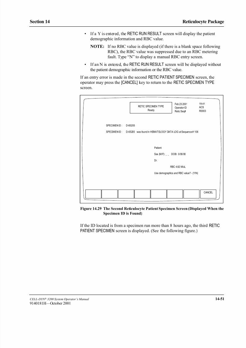
8/21/2019 Equ22-14 CellDyn3200 Op Man
http://slidepdf.com/reader/full/equ22-14-celldyn3200-op-man 643/690
CELL-DYN ® 3200 System Operator’s Manual 14-51
9140181H—October 2001
Section 14 Reticulocyte Package
• If a Y is entered, the RETIC RUN RESULT screen will display the patient
demographic information and RBC value.
NOTE: If no RBC value is displayed (if there is a blank space following
RBC), the RBC value was suppressed due to an RBC metering
fault. Type “N” to display a manual RBC entry screen.
• If an N is entered, the RETIC RUN RESULT screen will be displayed without
the patient demographic information or the RBC value.
If an entry error is made in the second RETIC PATIENT SPECIMEN screen, the
operator may press the [CANCEL] key to return to the RETIC SPECIMEN TYPEscreen.
Figure 14.29 The Second Reticulocyte Patient Specimen Screen (Displayed When the
Specimen ID is Found)
If the ID located is from a specimen run more than 8 hours ago, the third RETICPATIENT SPECIMEN screen is displayed. (See the following figure.)
RETIC SPECIMEN TYPE
Ready
Feb 23 2001
Operator ID
Retic Seq#
19:41
R0003
ACS
CANCEL
SPECIMEN ID : D-65205
SPECIMEN ID : D-65205 was found in HEMATOLOGY DATA LOG at Sequence # 106
Patient:
Sex (M/F): _ _ DOB: 0/00/00
Dr.
RBC 4.62 M/uL
Use demographics and RBC value? - (Y/N)

8/21/2019 Equ22-14 CellDyn3200 Op Man
http://slidepdf.com/reader/full/equ22-14-celldyn3200-op-man 644/690
14-52 CELL-DYN ® 3200 System Operator’s Manual
9140181H—October 2001
Reticulocyte Package
Routine Operation Section 14
Figure 14.30 The Third Reticulocyte Patient Specimen Screen (Displayed When the
Specimen ID Found is More Than Eight Hours Old)
RETIC SPECIMEN TYPE
Ready
Aug 03 2001
Operator ID
Retic Seq#
16:29
R0484
TS
CANCEL
ENTER SPECIMEN ID: d17484 Press ENTER to confirm.SPECIMEN ID: D17484 was found in HEMATOLOGY DATA LOG but specimen data are more than 8 hours old . . .
Enter RBC value - - - - - - - M/uL. Press ENTER to confirm.
Press ENTER to continue if no Hematology Specimen result is available.If no RBC value is entered, only RETIC% will be calculated.

8/21/2019 Equ22-14 CellDyn3200 Op Man
http://slidepdf.com/reader/full/equ22-14-celldyn3200-op-man 645/690
CELL-DYN ® 3200 System Operator’s Manual 14-53
9140181H—October 2001
Section 14 Reticulocyte Package
If the Specimen ID is not found in the Standard Hematology Data Log, the fourth
RETIC PATIENT SPECIMEN screen is displayed. (See the following figure.) This
screen displays a place for the operator to enter the RBC value. If an entry error is
made in the fourth RETIC PATIENT SPECIMEN screen, the operator may press the
[CANCEL] key to return to the RETIC SPECIMEN TYPE screen. If the operator presses
the Enter key to confirm the RBC value, the RETIC RUN RESULT screen isdisplayed.
Figure 14.31 The Fourth Reticulocyte Patient Specimen Screen (Displayed When the
Specimen ID Is Not Found)
RETIC SPECIMEN TYPE
Ready
Aug 03 2001
Operator ID
Retic Seq#
16:35
R0484
TS
CANCEL
SPECIMEN ID: 111SPECIMEN ID: 111 was found in HEMATOLOGY DATA LOG.
Enter RBC value - - - - - - - M/uL. Press ENTER to confirm.
Press ENTER to continue if no Hematology Specimen result is available.If no RBC value is entered, only RETIC% will be calculated.

8/21/2019 Equ22-14 CellDyn3200 Op Man
http://slidepdf.com/reader/full/equ22-14-celldyn3200-op-man 646/690
14-54 CELL-DYN ® 3200 System Operator’s Manual
9140181H—October 2001
Reticulocyte Package
Routine Operation Section 14
Retic Run Result Screen
Figure 14.32 The Reticulocyte Run Result Screen for a Patient Specimen
Upper Left Corner
The numbers in the upper left-hand corner of the RETIC RUN RESULT screen
(shown in the preceding figure) correspond with the following numbered data entry
fields:
1. <Spec ID> This data entry field automatically displays the specimen ID
(up to 12 characters), which was previously entered on the
RETIC PATIENT SPECIMEN screen.
2. <Name> This data entry field automatically displays the patient’s
name if it was found in the Standard Hematology Data
Log when the patient specimen ID was entered into the
first RETIC PATIENT SPECIMEN screen. If the information
was not found in the Standard Hematology Data Log, the
patient name can be entered here (up to 16 characters).
NOTE: If an entry error is made in the second RETIC PATIENT SPECIMEN
screen, the operator may press the [CANCEL] key to return to the
RETIC SPECIMEN TYPE screen.
3. <Pat ID> This field may be used to enter patient identification such as
a social security number. (Up to 16 characters may be
entered.)
NEXT
RETIC
RETIC RUN RESULT
Ready
Aug 02 2001
Operator ID
Retic Seq#
13:47
R0481
TS
RETICCOLOR
Spec ID D17516
Name ________________
Pat ID _________ Sex ___
DOB __/__/____ Col __/__/____ --:--
Dr _______________ Cmt _________
Limits 1
RETIC% 1.63 %
RBC 4.68 M/uL
RETIC ABS 76.00 K/uL
RBC value from HEMATOLOGY
DATA LOG Sequence # 8842
MAIN

8/21/2019 Equ22-14 CellDyn3200 Op Man
http://slidepdf.com/reader/full/equ22-14-celldyn3200-op-man 647/690
CELL-DYN ® 3200 System Operator’s Manual 14-55
9140181H—October 2001
Section 14 Reticulocyte Package
4. <Sex (M/F)> This data entry field automatically displays the sex and
5. <DOB> birthdate of the patient if it was found in the Standard
Hematology Data Log. If the information was not found
in the Standard Hematology Data Log, the sex and birth
date of the patient can be entered here.
6. <Col> This field is used to enter the collection date and time forthe specimen. (4 digits must be entered for the year)
7. <Dr> This data entry field automatically displays the name of
the patient’s doctor if it was found in the Standard
Hematology Data Log. If the information was not found
in the Standard Hematology Data Log, the name of the
patient’s doctor can be entered here (up to 22 characters).
8. <Cmt> This field is used to enter the comments. (Up to 16
characters may be entered.)
9. <Limits> This data entry field automatically displays the number of
the Limit Set that will be applied to the sample results.
NOTE: The Limit Set applied to the reticulocyte sample may be changed
after the specimen has been run. Refer to the description for the
[EDIT SPECIMEN] key given in Reticulocyte Menu Options,
Reticulocyte Data Log Menu, Display Specimen Soft Key within
this chapter.
These demographics can be entered or changed before the Reticulocyte specimen
is processed, or while the EDIT SPECIMEN screen in the Reticulocyte Data Log is
displayed.
Top Center
The Status Box is displayed in the top center of the RETIC RUN RESULT screen. This box appears on every screen to show the following information:
• The menu in use (such as RETIC RUN RESULT).
• The status of the Analyzer (such as Ready, Not ready, and FAULT
messages).
• Status and instructive messages. During the Reticulocyte Run cycle these are:
Aspirating
Remove Specimen
Dispensing
Rinsing
Ready

8/21/2019 Equ22-14 CellDyn3200 Op Man
http://slidepdf.com/reader/full/equ22-14-celldyn3200-op-man 648/690
14-56 CELL-DYN ® 3200 System Operator’s Manual
9140181H—October 2001
Reticulocyte Package
Routine Operation Section 14
Upper Right Corner
The upper right-hand corner of the RETIC RUN RESULT screen displays the
following information:
• The current date and time.
• The Operator ID (which identifies the current operator).
• The Reticulocyte Sequence Number. ("R _ _ _ _ ," which automatically
increments as reticulocyte samples are run.)
Center
The center section of the RETIC RUN RESULT screen displays the results. The list of
the parameters and results is displayed on the left side. The information on RBC
value entry is also displayed on the left side. The scatterplots, and the histograms
are displayed on the right. The red blood cells are shown in red, the reticulocytes
are shown in blue, the nucleated cells are shown in white (black on the color
printout), the immature Reticulocytes are shown in cyan (light blue), and
coincidence passage events are shown in green and the noise is shown in yellow.
Any alert messages will appear in the lower left-hand corner of the screen.
The following soft key labels are displayed on the RETIC RUN RESULT screen:
NEXT RETIC (This soft key label displays when the Reticulocyte
specimen run has been completed.)
PRINT REPORT/COLOR PRINT (The key label alternates between the selections)
RETIC MAIN (This key is used to return to the RETIC SPECIMENTYPE screen.)

8/21/2019 Equ22-14 CellDyn3200 Op Man
http://slidepdf.com/reader/full/equ22-14-celldyn3200-op-man 649/690
CELL-DYN ® 3200 System Operator’s Manual 14-57
9140181H—October 2001
Section 14 Reticulocyte Package
QC Specimen
Figure 14.33 Reticulocyte Run Result Screen for a QC Specimen
When the [QC SPECIMEN] key on the RETIC SPECIMEN TYPE screen is pressed, the
QC file where the cursor is positioned is opened and the RETIC RUN RESULT screen
for QC specimens is displayed. (See the preceding figure.) Results from the QC run
option are stored in the selected reticulocyte QC file and in the Reticulocyte DataLog.
RETIC RUN RESULT
Ready
Feb 23 2001
Operator ID
Retic Seq#
19:58
R0003
ACS
CANCEL
Lot Number: 65185
File: SCORTE 0/120
RETIC %

8/21/2019 Equ22-14 CellDyn3200 Op Man
http://slidepdf.com/reader/full/equ22-14-celldyn3200-op-man 650/690
14-58 CELL-DYN ® 3200 System Operator’s Manual
9140181H—October 2001
Reticulocyte Package
Routine Operation Section 14
Background
Figure 14.34 Reticulocyte Run Result Screen for a Background Specimen
When the [BACKGROUND] key on the RETIC SPECIMEN TYPE screen is pressed, the
RETIC RUN RESULT screen for background counts is displayed. (See the preceding
figure.) Results from this run option are identified by the designation
BACKGROUND on the RETIC RUN RESULT screen and in the Retic Data Log.
Retic Main
When the [RETIC MAIN] key is pressed, the RETIC MAIN menu screen is displayed.
RETIC RUN RESULT
Ready
Feb 23 2001
Operator ID
Retic Seq#
19:58
R0003
ACS
CANCEL
Type: BACKGROUND
Background Count found inRetic area
For Retic Backgroound, runthe Retic Reagent.

8/21/2019 Equ22-14 CellDyn3200 Op Man
http://slidepdf.com/reader/full/equ22-14-celldyn3200-op-man 651/690
CELL-DYN ® 3200 System Operator’s Manual 14-59
9140181H—October 2001
Section 14 Reticulocyte Package
Reticulocyte Specimens
Overview
This subsection discusses routine operation of the Reticulocyte Package.
Guidelines and procedures are provided for running background counts, quality
control, and patient specimens. Proper start-up procedures should be performed
prior to processing patient specimens. The Reticulocyte Package is only available
for use in the Open Sampler Mode.
For background counts, a tube of reticulocyte reagent is run without an aliquot of
whole blood, to check for particulate material in the reagent and system.
Control material should be properly warmed and mixed according to the
manufacturer’s recommendations. Patient reticulocyte controls should be run and
handled according to the laboratory’s protocol. Quality control checks (which
verify Reticulocyte Package performance) should be performed on each shift that
reticulocyte samples are run according to the laboratory’s protocol.
Each reticulocyte sample is run by starting from the RETIC SPECIMEN TYPE screen.The operator selects the type of Reticulocyte specimen to be run (Patient, QC, or
Background) and proceeds through the screen(s) displayed for that specimen type.
When the reticulocyte sample is completed, the [NEXT RETIC] key is displayed.
When the [NEXT RETIC] key is pressed, the operator can then select the specimen
type for the next specimen. Specific instructions for each specimen type are given
later in this section.
CAUTION: When using the reticulocyte reagent, avoid contact with skin
and clothing. This reagent contains New Methylene Blue, which will stain
skin, clothing, and many other surfaces.
WARNING: Potential Biohazard. Consider all clinical specimens andcontrols that contain human blood or serum as potentially infectious. Use
established, good laboratory working practices when handling these
specimens. Wear appropriate personal protective equipment and follow
other biosafety practices as specified in the OSHA Bloodborne Pathogen
Rule or other equivalent biosafety procedures.
Specimen Requirements
A fresh non-hemolyzed, whole blood specimen collection in K 2EDTA, K 3EDTA
or NA2EDTA is the specimen of choice for Reticulocyte analysis on the
CELL-DYN 3200 System.
Specimens may be run up to 8 hours after collection time when stored at roomtemperature.
NOTE: Studies have shown that reticulocytes continue to mature at room
temperature. Increased flagging can occur when using specimens more
than 8 hours old.
If a delay in analysis is anticipated, specimens may be processed up to 72 hours if
stored at refrigerated temperature.
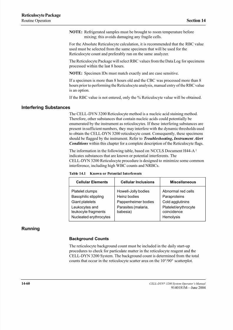
8/21/2019 Equ22-14 CellDyn3200 Op Man
http://slidepdf.com/reader/full/equ22-14-celldyn3200-op-man 652/690
14-60 CELL-DYN ® 3200 System Operator’s Manual
9140181M—June 2004
Reticulocyte Package
Routine Operation Section 14
NOTE: Refrigerated samples must be brought to room temperature before
mixing; this avoids damaging any fragile cells.
For the Absolute Reticulocyte calculation, it is recommended that the RBC value
used must be selected from the same specimen that will be used for the
Reticulocyte count and preferably run on the same analyzer.
The Reticulocyte Package will select RBC values from the Data Log for specimens
processed within the last 8 hours.
NOTE: Specimen IDs must match exactly and are case sensitive.
If a specimen is more than 8 hours old and the CBC was processed more than 8
hours prior to performing the Reticulocyte analysis, manual entry of the RBC value
is an option.
If the RBC value is not entered, only the % Reticulocyte value will be obtained.
Interfering Substances
The CELL-DYN 3200 Reticulocyte method is a nucleic acid staining method.Therefore, other substances that contain nucleic acids could potentially be
enumerated by the instrument as reticulocytes. If these interfering substances are
present in sufficient numbers, they may interfere with the dynamic thresholds used
to obtain the CELL-DYN 3200 reticulocyte count. Consequently, these specimens
should be flagged by the instrument. Refer to Troubleshooting, Instrument Alert
Conditions within this chapter for a complete description of the Reticulocyte flags.
The information in the following table, based on NCCLS Document H44-A1
indicates substances that are known or potential interferents. The
CELL-DYN 3200 Reticulocyte procedure is designed to minimize some common
interference, including high WBC counts and NRBCs.
Running
Background Counts
The reticulocyte background count must be included in the daily start-up
procedures to check for particulate matter in the reticulocyte reagent and the
CELL-DYN 3200 System. The background count is determined from the total
counts that occur in the reticulocyte scatter area on the 10°/90° scatterplot.
Table 14.1 Known or Potential Interferents
Cellular Elements Cellular Inclusions Miscellaneous
Platelet clumps
Basophilic stippling
Giant platelets
Leukocytes and
leukocyte fragments
Nucleated erythrocytes
Howell-Jolly bodies
Heinz bodies
Pappenheimer bodies
Parasites (malaria,
babesia)
Abnormal red cells
Paraproteins
Cold agglutinins
Platelet/erythrocyte
coincidence
Hemolysis

8/21/2019 Equ22-14 CellDyn3200 Op Man
http://slidepdf.com/reader/full/equ22-14-celldyn3200-op-man 653/690
CELL-DYN ® 3200 System Operator’s Manual 14-61
9140181L—July 2003
Section 14 Reticulocyte Package
Procedure: Background Count
1. Select a tube from the current lot of reticulocyte reagent that will be used for
the day’s testing.
2. Label the tube “Retic Background” and record the current date on the tube.
NOTE: One tube may be used to check daily background counts for a one-week period, provided the reagent is not contaminated.
3. Turn the Reticulocyte Package ON as directed in Retic Menu Options,
Turning the Reticulocyte Package ON and OFF within this chapter.
4. From the RETIC MAIN menu screen, press the [RETIC RUN] key followed by
the [BACKGROUND] key.
5. Be sure that the READY indicator light on the Analyzer Status Indicator
Panel is illuminated in green and the word Ready is displayed in the Status
Box on the RETIC RUN RESULT screen.
6. Open the tube labeled “Retic Background” and immerse the Open Sample
Aspiration Probe in the reagent.
7. Press the Touch Plate located behind the probe to start the cycle. The BUSY
indicator light will be illuminated in yellow on the Analyzer Status Indicator
Panel. The Status Box on the RETIC RUN RESULT screen will display
messages indicating the various stages of the cycle.
8. Remove the tube when the beep sounds. The Wash Block will move down the
probe and clean it.
9. When the cycle is complete, the Wash Block moves back to the top of the
probe and the Ready message is displayed in the Status Box.
10. The screen displays the background count results as
Background Count Found in Retic Area.
11. Verify that the background count is within the acceptable limit of less than
100 counts.
NOTE: Results that are outside the acceptable range are displayed in
purple.
12. If the background count is unacceptable, repeat it. If the repeated count is still
unacceptable, follow the directions for troubleshooting background count
problems given in Troubleshooting later in this section.
Quality Control
Quality control checks should be performed, at a minimum, each day that
reticulocyte specimens are run or as required according to the laboratory’s
protocol. Control material should be properly warmed and prepared according tothe manufacturer’s recommendations. Patient controls should be handled
according to the laboratory’s protocol. For customizing the QC files see Retic
Menu Options, in this chapter.

8/21/2019 Equ22-14 CellDyn3200 Op Man
http://slidepdf.com/reader/full/equ22-14-celldyn3200-op-man 654/690
14-62 CELL-DYN ® 3200 System Operator’s Manual
9140181H—October 2001
Reticulocyte Package
Routine Operation Section 14
Procedure: Quality Control
1. Warm the control material according to the manufacturer’s
recommendations. See Quality Control, Mixing and Handling within this
chapter.
2. Use reticulocyte reagent and verify the expiration date. Store the stock
reagent in the dark at room temperature.
3. Label one tube of reticulocyte reagent for each level of control material.
4. Pipette 20 µL of the control material into each labeled tube of reticulocyte
reagent.
5. Incubate the prepared control specimens for 15 minutes, on the rotator or in
a rack, after fully inverting the stained specimens 5 times. Incubation is
performed at room temperature according to the reagent package insert.
NOTE: The stained control specimens may incubate for up to 30 minutes
prior to processing on the CELL-DYN 3200 System.
6. Verify that the Reticulocyte Package is turned ON. For instructions on
turning ON the Reticulocyte Package, refer to Retic Menu Options, Turningthe Reticulocyte Package ON and OFF within this chapter.
7. From the RETIC MAIN menu screen press the [RETIC RUN] key.
8. From the RETIC SPECIMEN TYPE screen, move the cursor to the desired QC
file and press the [QC SPECIMEN] key. The RETIC RUN RESULT screen for QC
specimens is displayed. The control file information is located in the upper
left-hand corner of the screen.
9. Open the well-mixed, prepared control specimen tube and immerse the Open
Sample Aspiration Probe in the sample.
10. Press the Touch Plate located behind the probe to start the cycle. The BUSY
indicator light on the Analyzer Status Indicator Panel will be illuminated in
yellow. The Status Box on the RETIC RUN RESULT screen will displaymessages to indicate the various stages of the cycle.
11. Remove the tube when the beep sounds. The Wash Block moves down the
probe and cleans it.
12. When the cycle is completed, the Wash Block moves up the probe and the
word READY displays in the status box.
13. Repeat steps 8 through 12 for all prepared control specimens.
14. Verify that the control results are acceptable.
NOTE: Out-of-range results are displayed in color. Data invalidating alerts,
such as Fragile RBCs, are not valid when running commercial
controls.15. If the results are unacceptable, repeat the run. If the results are still
unacceptable, run the other levels of the control material. If the results are
still unacceptable, prepare another stained dilution of that level of the control
material. If the results on all levels are unacceptable, troubleshoot
accordingly. See Section 10: Troubleshooting and Diagnostics.
16. When the control results are acceptable, patient samples may be analyzed.

8/21/2019 Equ22-14 CellDyn3200 Op Man
http://slidepdf.com/reader/full/equ22-14-celldyn3200-op-man 655/690
CELL-DYN ® 3200 System Operator’s Manual 14-63
9140181H—October 2001
Section 14 Reticulocyte Package
Specimen Preparation
CAUTION: When using the reticulocyte reagent, avoid contact with skin
and clothing. This reagent contains New Methylene Blue, which will stain
skin, clothing, and many other surfaces.
WARNING: Potential Biohazard. Consider all clinical specimens and
controls that contain human blood or serum as potentially infectious. Use
established, good laboratory working practices when handling these
specimens. Wear appropriate personal protective equipment and follow
other biosafety practices as specified in the OSHA Bloodborne Pathogen
Rule or other equivalent biosafety procedures.
Procedure: Specimen Preparation
1. The Reticulocyte Package is available for use only in the Open Sampler
Mode.
2. Use reticulocyte reagent and verify the expiration date. Store the stock
reagent in the dark at room temperature.
3. Label a tube of reticulocyte reagent for each patient.
4. Verify that the whole blood specimen is warmed to room temperature and
well mixed prior to sampling.
5. Pipette 20 µL of the whole blood specimen into each labeled tube of
reticulocyte reagent.
6. Incubate the stained Reticulocyte specimens on the rotator or in a rack, after
fully inverting the stained specimens 5 times. Incubation must be performed
according to the reagent package insert.
NOTE: The stained Reticulocyte specimens must incubate for 15 minutes
but no more than 2 hours prior to processing on the
CELL-DYN 3200 System.
This timing will allow the Reticulocyte specimens to be processed for STAT
requests. Reticulocyte specimens can also be grouped and run in batches, provided
that the 2-hour incubation time limit is not exceeded.
Specimen Analysis
Specimen analysis is performed in the Open Mode.
NOTE: To ensure optimal flagging, the CBC must have been run within 8 hours
prior to the Retic run on the same analyzer using the same specimen.
NOTE: Specimen IDs must match exactly and are case sensitive.
Procedure: Running Patient Samples
1. Press the [RETIC RUN] key to display the RETIC SPECIMEN TYPE menu. Press
the [PATIENT SPECIMEN] key to display the RETIC PATIENT SPECIMEN screen.
2. From the RETIC PATIENT SPECIMEN screen enter the Specimen ID and press
the Enter key on the keyboard to start the search process. The Standard
Hematology Data Log for the last 8 hours will be searched for this Specimen
ID.

8/21/2019 Equ22-14 CellDyn3200 Op Man
http://slidepdf.com/reader/full/equ22-14-celldyn3200-op-man 656/690
14-64 CELL-DYN ® 3200 System Operator’s Manual
9140181H—October 2001
Reticulocyte Package
Routine Operation Section 14
3. If the Specimen ID is found, the second RETIC PATIENT SPECIMEN screen is
displayed. All the available patient demographic information, and the RBC
value, are shown on the screen. Proceed to step 4.
If the Specimen ID is found but is more than 8 hours old, the third RETICPATIENT SPECIMEN screen is displayed and the operator may enter an RBC
value in this screen. Proceed to step 5.
If the Specimen ID is not found, the fourth RETIC PATIENT SPECIMEN screen
is displayed and the operator may enter an RBC value in this screen. Proceed
to step 5.
4. Press Y on the keyboard to save this demographic information.
NOTE: If the Enter key was pressed in error, or if the patient demographic
information is incorrect, press the [CANCEL] key to return to the
RETIC SPECIMEN TYPE screen, press the [PATIENT SPECIMEN] key,
return to step 2.
5. Press the Enter key on the keyboard to confirm and accept this information.
6. The RETIC RUN RESULT screen is now displayed. The area in the upper left-hand corner displays the patient demographic information.
NOTE: The patient demographic data can be added or edited on this screen
before the specimen is run, or from the EDIT SPECIMEN screen in
the Reticulocyte Data Log after the reticulocyte run is complete.
7. The prepared dilution(s) of the patient reticulocyte sample(s) can be run after
the control and background count results have met the laboratory’s criteria.
8. Open the well-mixed, prepared patient reticulocyte sample tube and immerse
the Open Sample Aspiration Probe in the sample.
9. Press the Touch Plate located behind the probe to start the cycle. The BUSY
indicator light on the Analyzer Status Indicator Panel will be illuminated in
yellow. The Status Box on the RETIC RUN RESULT screen will display
messages to indicate the various stages of the cycle.
10. Remove the sample tube when the beep sounds. The Wash Block moves
down the probe and cleans it.
11. When the rinse cycle is complete, the Wash Block moves up the probe. The
[NEXT RETIC] key is now displayed, and the Touch Plate is no longer active.
The results of the reticulocyte run are displayed on the screen.
12. If automatic report printing has been specified, a report is printed according
to the options selected in the SET UP MENU. If automatic report printing has
not been specified, a report may be printed by pressing the [PRINT REPORT] key. Repeat this procedure for each subsequent reticulocyte sample.
NOTE: To obtain a color printout, the color printing option on the CUSTOMIZE PRINTED REPORT screen must be turned ON.
13. Reticulocyte patient sample results can also be printed from the RETICDISPLAY SPECIMEN screen, available from the RETIC DATA LOG screen.

8/21/2019 Equ22-14 CellDyn3200 Op Man
http://slidepdf.com/reader/full/equ22-14-celldyn3200-op-man 657/690
CELL-DYN ® 3200 System Operator’s Manual 14-65
9140181M—June 2004
Section 14 Reticulocyte Package
Quality Control Guide
The CELL-DYN 3200 System offers several quality control options to monitor andvalidate instrument performance while running the Reticulocyte Package. The
options are:
• 6 QC Files Statistical and graphical analysis of the data in each
file to calculate the mean, standard deviation, and
coefficient of variation
• Westgard Rules A multi-rule system applied to the data in each of the
QC files
Each of these options is discussed in detail in Section 11: Quality Control .
All QC data should be reviewed according to your laboratory’s protocol.
Control Material
Abbott Diagnostics recommends using the CELL-DYN Retic-RITE® control
material for performing quality control checks on the CELL-DYN 3200 System.
These controls should be run:
• After daily start-up procedures are completed.
• After a reagent lot number change.
• After a service call or component replacement.
• After calibrating the Standard Hematology Mode.
• In accordance with the laboratory’s quality control protocol.
• According to regulatory requirements.
NOTE: Data invalidating alerts, such as Fragile RBC or ERL, are not valid
when running commercial controls.
Mixing and Handling
CAUTION: When using the reticulocyte reagent, avoid contact with skin
and clothing. This reagent contains New Methylene Blue, which will stain
skin, clothing, and many other surfaces.
Reagent
• Use Reticulocyte Reagent prepared only by Abbott Laboratories. Verify the
expiration date.
• Store the Reticulocyte Reagent in the dark at room temperature.
• Use one Reticulocyte Reagent tube for each CELL-DYN Retic-RITE®
control or patient specimen.

8/21/2019 Equ22-14 CellDyn3200 Op Man
http://slidepdf.com/reader/full/equ22-14-celldyn3200-op-man 658/690
14-66 CELL-DYN ® 3200 System Operator’s Manual
9140181M—June 2004
Reticulocyte Package
Quality Control Guide Section 14
Quality Control Specimens
Always mix and handle commercial control material according to the directions
given in the package insert. Pay particular attention to the following:
• Store the CELL-DYN Retic-RITE® controls in the refrigerator at 2°– 8° C.
Store in a suitable location in the refrigerator, away from the door if it is
opened frequently.
• Carefully warm the CELL-DYN Retic-RITE® controls prior to mixing,
according to the directions given in the package insert. Proper mixing is
essential for accurate results.
• Mix the CELL-DYN Retic-RITE® control vials gently by hand to thoroughly
resuspend the control material. Do not use automatic mixers to resuspend the
control material.
• Check the open-vial stability dating given on the package insert and do not
use the products longer than is recommended or results may be
compromised.

8/21/2019 Equ22-14 CellDyn3200 Op Man
http://slidepdf.com/reader/full/equ22-14-celldyn3200-op-man 659/690
CELL-DYN ® 3200 System Operator’s Manual 14-67
9140181H—October 2001
Section 14 Reticulocyte Package
Troubleshooting
OverviewThis section provides instructions for identifying, troubleshooting, and correcting
instrument alerts and conditions in the Reticulocyte Package. All instrument
conditions which adversely affect the Standard Hematology Mode of the
CELL-DYN 3200 System will also apply to the Reticulocyte Package. These
instrument conditions may be found in Section 10: Troubleshooting and
Diagnostics.
This section is divided into the following subsections:
• General Guidelines for Reticulocyte Troubleshooting
• Operational Messages and Data Flagging
• Dispersional Data Alerts
• Instrument Alert Messages
• Alert Messages with Suppressed Reticulocyte Results
• Data Invalidating Alerts
• High Background Counts
NOTE: For a list of interfering substances, refer to Routine Operation,
Reticulocyte Specimens, Interfering Substances within this
chapter.
General Guidelines for Reticulocyte Troubleshooting
Reticulocyte troubleshooting should include an initial check of the following
items:
• Reagent storage conditions and expiration. (Refer to Retic Reagent package
insert for details).
• Sample preparation technique including pipetting, mixing, and incubation.
(Refer to Routine Operation within this section.)
• Overall system maintenance. (Refer to Section 9: Service and Maintenance;
Subsection: Preventive Maintenance Schedule.)

8/21/2019 Equ22-14 CellDyn3200 Op Man
http://slidepdf.com/reader/full/equ22-14-celldyn3200-op-man 660/690
14-68 CELL-DYN ® 3200 System Operator’s Manual
9140181K—July 2002
Reticulocyte Package
Troubleshooting Section 14
Operational Messages and Data Flagging
Dispersional Data Alerts
The result of each run (patient, control, or background) is reviewed within the
appropriate limits as entered by the operator or taken from the instrument’s presetlimits. If a result for a parameter exceeds these limits, they are flagged on the screen
and on the report. Dispersional Data Alerts are displayed or printed as follows:
Data Station Screen Display:
• Result(s) below lower limits shown in yellow
• Result(s) above upper limits shown in purple
Linearity Exceeded: Result displayed as >>>>
Reticulocyte QC Log: Result(s) outside limits underlined when printed
Reticulocyte Data Log: Result(s) outside limits underlined when printed
Graphics Report: Result(s) outside limits underlined
Instrument Alert Messages
Instrument Alert Messages are displayed when the instrument detects an
inappropriate condition during specimen processing. When necessary, data is
suppressed. When these messages occur, follow the instructions given, and take the
appropriate corrective action. When the problem is corrected, repeat the specimen.
Instrument Alert Messages with Suppressed Reticulocyte Results
Suppression of Reticulocyte results occurs when the sample run data acquisition
process exceeds normal parameters. When the Reticulocyte results are suppressed,
one of the following three alerts will be displayed in the lower left-hand quadrant
of the Display Monitor screen in the Reticulocyte Package and on the graphics printout under the heading ALERTS.
Table 14.2 Instrument Alert Messages
Alert Probable Cause Corrective Action
Flow Error
NOTE: Alert occurs when
the average count rate
rapidly increases during the
Reticulocyte count cycle.
• Air bubble
• Hardware malfunction
1. Run a background count to cycle air through
the system.
2. Rerun the Reticulocyte specimen.
3. If alert still occurs, refer to Section 10:
Troubleshooting and Diagnostics;
Subsection: Troubleshooting Flow Errors.
Too Few Events
NOTE: Alert occurs when
fewer than 3000 events are
counted during the
Reticulocyte count cycle.
• Inadequate wholeblood sample mixing
- Improper pipetting
- Blood not stained
•
Cold Agglutinin
1. Prepare another dilution verifying properspecimen preparation as discussed in
Routine Operation, Reticulocyte
Specimens, Running Specimens, Patient,
Specimen Preparation within this chapter.
2. Verify Reticulocyte results by an alternate
method.
>>>> (Chevrons) • The Reticulocyte
percentage exceeds the
reportable linear range.
1. Verify Reticulocyte results by an alternate
method.

8/21/2019 Equ22-14 CellDyn3200 Op Man
http://slidepdf.com/reader/full/equ22-14-celldyn3200-op-man 661/690
CELL-DYN ® 3200 System Operator’s Manual 14-69
9140181M—June 2004
Section 14 Reticulocyte Package
Data Invalidating Alerts
The Reticulocyte results are not suppressed for the Data Invalidating Alerts. The
alert message appears in the lower left-hand quadrant of the Display Monitor
screen and on the graphics printout under the heading ALERTS.
High Background Counts
NOTE: The background count should be less than 100 counts.
1. If the background count is high, repeat the run.
2. If the results are still unacceptable, open a new tube of reticulocyte reagent
and repeat the background count.
3. If the background count is still unacceptable, run a tube from a new lot ofreticulocyte reagent if available.
4. If the results are still unacceptable, while in the Reticulocyte Background
mode, press the Touch Plate to cycle air through the system.
5. If the results are still unacceptable, exit the Reticulocyte Package and
perform a background check in the Standard Hematology mode.
Table 14.3 Data Invalidating Alerts
Alert Probable Cause Corrective Action
Fragile RBCs
NOTE: Alert occurs when the
average count rate rapidly
decreases during the
Reticulocyte count cycle.
• Air bubble
• Staining a fragile RBC
specimen too long in the
reticulocyte reagent
• Fragile RBCs
1. Run a background count to cycle air
through the system. Rerun the
Reticulocyte specimen.
2. Prepare another dilution verifying proper
specimen preparation as discussed in
Routine Operation, Reticulocyte
Specimens, Running Specimens,
Patient, Specimen Preparation within
this chapter. Run the dilution after
adequate incubation as indicated in theReagent package insert.
3. Verify Reticulocyte results by an alternate
method.
Excessive RBC Loss (ERL) • Specimen staining time
too long in the
reticulocyte reagent
• Rapid degeneration of
RBCs.
• High concentration of
platelets, platelet
aggregates, or other
interfering substances.
• Microcytic RBCs
• Improper instrument
settings
1. Prepare another dilution verifying proper
specimen preparation as discussed in
Routine Operation, Reticulocyte
Specimens, Running Specimens,
Patient, Specimen Preparation within
this chapter, and run after adequate
incubation as indicated in the Reagent
package insert.
2. Rerun the specimen.3. If the flag persists, verify the reticulocyte
results by an alternative method.

8/21/2019 Equ22-14 CellDyn3200 Op Man
http://slidepdf.com/reader/full/equ22-14-celldyn3200-op-man 662/690
14-70 CELL-DYN ® 3200 System Operator’s Manual
9140181M—June 2004
Reticulocyte Package
Troubleshooting Section 14
6. If the background in the Standard Hematology mode is unacceptable, see
Section 10: Troubleshooting and Diagnostics; Subsection:
Troubleshooting High Background Counts.
NOTE: Reticulocyte counts can not be processed until the reticulocyte
background count is acceptable.
8/21/2019 Equ22-14 CellDyn3200 Op Man
http://slidepdf.com/reader/full/equ22-14-celldyn3200-op-man 663/690
CELL-DYN ® 3200 System Operator’s Manual 14-71
9140181M—June 2004
Section 14 Reticulocyte Package
References
1. National Committee for Clinical Laboratory Standards. Methods for Reticulocyte Counting (Flow Cytometry and Supravital Dyes); Approved
Standard. NCCLS document H44-A (ISBN 1-56238-302-7). NCCLS, 940
West Valley Road, Suite 1400, Wayne, Pennsylvania 19087, 1997.
2. National Committee for Clinical Laboratory Standards. Method Comparison
and Bias Estimation Using Patient Samples; Approved Guideline. NCCLS
document EP9-A (ISBN 1-56238-283-7) NCCLS, 940 West Valley Road,
Suite 1400, Wayne, PA 19087-1898, 1995.
3. National Committee for Clinical Laboratory Standards. Evaluation of the
Linearity of Quantitative Analytical Methods, Proposed Guideline. NCCLS
document EP6-P (ISBN 1-56238-019-2) 940 West Valley Road, Suite 1400,
Wayne, PA 19087-1898, 1986.4. International Committee for Standardization in Haematology (ICSH). The
Assignment of Values to Fresh Blood Used for Calibrating Automated Cell
Counters. Clinical and Laboratory Hematology 1988; 10:203-212.
5. Clinical Applications of Flow Cytometry. ASCP National Meeting. Spring
1990.
6. Shapiro, Howard. Practical Flow Cytometry. New York: LISS. 1985.

8/21/2019 Equ22-14 CellDyn3200 Op Man
http://slidepdf.com/reader/full/equ22-14-celldyn3200-op-man 664/690
14-72 CELL-DYN ® 3200 System Operator’s Manual
9140181M—June 2004
Reticulocyte Package
References Section 14
NOTES
8/21/2019 Equ22-14 CellDyn3200 Op Man
http://slidepdf.com/reader/full/equ22-14-celldyn3200-op-man 665/690
CELL-DYN ® 3200 System Operator’s Manual A-1
9140181H—October 2001
Appendix A Bar Codes
ppen x ar o es
Overview
This section gives a brief overview of what bar coding is, how bar code labels areused for data entry, and the different types of bar codes that may be used with the
CELL-DYN 3200 System.
Bar coding is an automated method of gathering alphanumeric information and
transmitting it to a computer. Because it eliminates typing and associated errors,
bar coding offers speed, increased accuracy, and efficiency. The following are the
major elements in a bar coding system:
• The computer and appropriate software interprets and stores bar code data.
For the CELL-DYN 3200 System, this is accomplished by the Data Station
and its software.
• The scanning device "decodes" the information on the bar code labels. The
Tower Module on the CELL-DYN 3200 System incorporates an integral bar
code reader, allowing the use of bar codes on both the SL and CS models.
• The bar code labels contain the specimen identification codes.
CAUTION: Ensure that specimen has been properly identified before
placing bar code label on specimen tube.
Bar Code Function
The bar code label contains the actual identifying data for specimens in the form of
a series of black bars and contrasting white spaces, which represent numbers and
letters. The arrangement of the code follows one of several sets of rules for bar code
languages, called symbologies. To decode the data in the label, a scanning device
is used to pass a small spot of light over the bars and spaces to read them.
Since dark bars reflect little light back into the scanning device, while white space
reflects a lot of light, a light detector inside the scanner can translate the differences
in reflection into electrical signals. The signals are then converted into the sets of
ones and zeros (the binary system used by computers) that stand for numbers and
letters.

8/21/2019 Equ22-14 CellDyn3200 Op Man
http://slidepdf.com/reader/full/equ22-14-celldyn3200-op-man 666/690
A-2 CELL-DYN ® 3200 System Operator’s Manual
9140181H—October 2001
Bar Codes
Overview Appendix A
Understanding the Label’s Code
In all bar code symbologies, the code consists of elements (single bars or white
spaces) and characters (groups of elements that stand for numbers or letters). In
code 39, a commonly used symbology, each code character contains nine elements,
at least three of which must be wide. Wide elements (whether they are bars or
spaces) in this symbology have a binary value of 1. Narrow elements have a binary
value of 0.
Most contemporary bar code systems have several features in common. These
include the following:
• The Quiet Zone is the area immediately before and after the bar code symbol.
This zone enables the scanner to read the code properly.
• Start and Stop Characters indicate the beginning and end of the bar code
symbol. They allow the label to be scanned from either right to left or left to
right, ensuring that code information is transmitted correctly.
• Intercharacter Gaps act as spaces between each character in the bar codesymbol. Code 39 contains these gaps. However, there are other codes, such
as Interleaved 2 of 5, that do not use them.
• The Interpretation Line is an area at the bottom of the bar code label where
human-readable information can be placed. This may or may not be the same
data as in the label code.
• The Check Digit is an extra numeric character in the bar code that permits the
scanning device to mathematically determine whether it read the code
correctly. This keeps the error rate as low as one for every billion characters
scanned.

8/21/2019 Equ22-14 CellDyn3200 Op Man
http://slidepdf.com/reader/full/equ22-14-celldyn3200-op-man 667/690
CELL-DYN ® 3200 System Operator’s Manual A-3
9140181H—October 2001
Appendix A Bar Codes
Bar Code Types and Characteristics
The CELL-DYN 3200 System reads four types of bar code labels:
• Code 39
• Code 128
• Interleaved 2 of 5
• Codabar
Code 39
Also referred to as code 3 of 9, Code 39 encodes 43 data characters: 0-9, A-Z, six
symbols, and spaces. Every Code 39 character has five bars and four spaces. Of
these nine elements, three are wide and six are narrow, making Code 39 a two-
width code.
Code 128
Code 128 has 106 different printed characters. Each character has three bars andthree spaces comprising 11 modules. Each printed character can have one of three
different meanings, depending on which of three different character sets is used.
Three different start characters tell the reader which of the character sets is initially
being used, and three shift codes permit changing the character set inside a symbol.
Interleaved 2 of 5
Interleaved 2 of 5 encodes the 10 numeric digits 0-9. The name is derived from the
method used to encode two characters that are paired together. Bars represent the
first character, and the interleaved spaces represent the second character. Each
character has two wide elements and three narrow elements, for a total of five
elements.
Codabar
Codabar uses four bars and three spaces to represent the 10 numeric digits 0-9 and
certain special characters. The code is characterized by four unique start/stop codes
and variable intercharacter spacing.
8/21/2019 Equ22-14 CellDyn3200 Op Man
http://slidepdf.com/reader/full/equ22-14-celldyn3200-op-man 668/690
A-4 CELL-DYN ® 3200 System Operator’s Manual
9140181H—October 2001
Bar Codes
Overview Appendix A
NOTES

8/21/2019 Equ22-14 CellDyn3200 Op Man
http://slidepdf.com/reader/full/equ22-14-celldyn3200-op-man 669/690
CELL-DYN ® 3200 System Operator’s Manual A-5
9140181H—October 2001
Appendix A Bar Codes
Specifications
Bar Code Label FormatsThe Bar Code Reader on the CELL-DYN 3200 System can read all four label types
listed below. Code size, collection tube length, and cap style limit the number of
digits to the following maximum numbers:
A minimum of three digits is required.
• Code 39 — 9 digits
• Code 128 — 11 digits
• Interleaved 2 of 5 — 10 or 12 digits only
• Codabar — 10 digits
NOTE: The maximum number of digits includes any check digits within
the code. For example, if one check digit is used in Code 39, then
only 8 digits can be used for the rest of the code.
Bar Code Check Digit Formats
Bar code Check Digits are used whenever the instrument is to read a specific type
of bar code. To enable or disable the check digit option, refer to Section 5:
Operating Instructions; Subsection: Bar Code Set Up.
Check Digit specifications are as follows:
• Code 39 - The modulus 43 sum of all the character values in a given message• Code 128 - The check digit is built into the Bar Code Reader.
• Interleaved 2 of 5 - The check digit is the complement of the weighted sum
of the digits modulo 10. To determine the weight of the digits, multiply every
other digit by 3, starting with the first.
• Codabar - The modulus 16 sum of all the character values in a given message.
NOTE: If a specific check digit option is selected and turned ON, the Bar
Code reader will read only bar codes in that specific format. If more
than one format will be used on the instrument, it is recommended
that the check digit option be turned OFF.

8/21/2019 Equ22-14 CellDyn3200 Op Man
http://slidepdf.com/reader/full/equ22-14-celldyn3200-op-man 670/690
A-6 CELL-DYN ® 3200 System Operator’s Manual
9140181M—June 2004
Bar Codes
Specifications Appendix A
Bar Code Label Specifications
Bar code labels must be printed on good quality label stock and must meet the
following specifications:
• 0.25 inch minimum quiet zone on each end
• 0.01 inch (10 mils) minimum narrow bar width
• 2:1 to 3:1 wide to narrow bar ratio
• 0.5 inch minimum bar length
• 2 inch maximum label length
• 1.25 inch maximum label width
• Maximum possible contrast between bars and background label
CELL-DYN Bar Code Labels
CELL-DYN 4-digit Code 39 bar code labels, in rolls of 1000 labels each, can beordered with list number List Number 99650-01. These labels may be used for
positive specimen identification when laboratory-generated bar code labels are
unavailable.
Bar Code Label Placement
CAUTION: Ensure that specimen has been properly identified before
placing bar code labels on specimen tubes.
The following two guidelines should be observed when placing bar code labels on
specimen tubes (refer to Figure A.1):
1. All labels should be placed on the tubes securely and without flaps stickingout. Refer to the following figure.
2. The bar code label should be placed on the tube just below the stopper with
the bars perpendicular to the length of the tube. This will ensure that the
entire bar code can be viewed through the slot in the rack as the tube rotates.
Be sure that at least 0.10 inch (about 1/8 inch) of space is left between (a) the
bar code symbol and the bottom of the rack slot and (b) between the bar code
symbol and tube cap. This spacing will satisfy the “quiet zone” requirement.
Refer to the following figure for proper bar code placement.
3. If more than one bar code label is placed on a tube, the first label that is read
when the tube spins is used to identify the specimen. The second label is
ignored. Consequently, the possibility for misidentification exists. Therefore,it is recommended that only one bar code label is used on each tube for
correct specimen identification.

8/21/2019 Equ22-14 CellDyn3200 Op Man
http://slidepdf.com/reader/full/equ22-14-celldyn3200-op-man 671/690
CELL-DYN ® 3200 System Operator’s Manual A-7
9140181H—October 2001
Appendix A Bar Codes
Figure A.1 Bar Code Placement Guide

8/21/2019 Equ22-14 CellDyn3200 Op Man
http://slidepdf.com/reader/full/equ22-14-celldyn3200-op-man 672/690
A-8 CELL-DYN ® 3200 System Operator’s Manual
9140181H—October 2001
Bar Codes
Specifications Appendix A
NOTES

8/21/2019 Equ22-14 CellDyn3200 Op Man
http://slidepdf.com/reader/full/equ22-14-celldyn3200-op-man 673/690
CELL-DYN ® 3200 System Operator’s Manual A-9
9140181H—October 2001
Appendix A Bar Codes
Bar Code Operation
The system can take a number of actions depending on the Bar Code Set Upconfiguration and the symbology of the label. A brief description of each possible
action is given below.
Code 39
If the Instrument is configured for Code 39 with Check Digit ON, the Instrument
will:
a. read a Code 39 label with check digit.
If the check digit on the label matches the check digit calculated by the
Instrument, the “read” is good and the Work List is searched for a
matching bar code number in the Specimen ID field. If a matching entry
is found in the Work List, the entry details are displayed in the
Demographics section of the RUN screen. When the result is available, it
is saved in the Data Log and the entry is deleted from the Work List. If
no matching entry is found, the specimen is identified in the Data Log by
the tube bar code number in the Specimen ID field.
If the check digits do not match, the “read” is not good and the Work List
is not searched. For SL models, the Rack and Tube # is assigned to the
Specimen ID field for that specimen in the Data Log. For CS models,
only the Sequence # is used to identify that specimen in the Data Log.
b. ignore all other bar code symbologies.
The Work List is not searched. For SL models, the specimen is identified
in the Data Log by the Rack and Tube number assigned to the Specimen
ID field by the Instrument. For CS models, the specimen is identified in
the Data Log by the Sequence number only and the Specimen ID field is
left blank.
8/21/2019 Equ22-14 CellDyn3200 Op Man
http://slidepdf.com/reader/full/equ22-14-celldyn3200-op-man 674/690
A-10 CELL-DYN ® 3200 System Operator’s Manual
9140181H—October 2001
Bar Codes
Bar Code Operation Appendix A
If the Instrument is configured for Code 39 with Check Digit OFF, the Instrument
will:
a. read all four bar code symbologies’ labels with a check digit.
The bar code reader reads the entire number including the check digit and
the Work List is searched. Because the bar code label has one extra digit(check digit), no matching entry will be found in the Work List (which
should not contain the check digit). The specimen is identified in the Data
Log by the tube bar code number in the Specimen ID field.
b. read all four bar code symbologies’ labels without a check digit.
The “read” is assumed to be good (without a check digit the bar code
number cannot be verified) and the Work List is searched for a matching
bar code number in the Specimen ID field. If a matching entry is found
in the Work List, the entry details are displayed in the Demographics
section of the RUN screen. When the result is available, it is saved in the
Data Log and the entry is deleted from the Work List. If no matching
entry is found, the specimen is identified in the Data Log by the tube bar
code number in the Specimen ID field.
8/21/2019 Equ22-14 CellDyn3200 Op Man
http://slidepdf.com/reader/full/equ22-14-celldyn3200-op-man 675/690
CELL-DYN ® 3200 System Operator’s Manual A-11
9140181H—October 2001
Appendix A Bar Codes
I2of5
If the Instrument is configured for I2of5 with Check Digit ON, the Instrument will:
a. read an I2of5 label with check digit.
If the check digit on the label matches the check digit calculated by theInstrument, the “read” is good and the Work List is searched for a
matching bar code number in the Specimen ID field. If a matching entry
is found in the Work List, the entry details are displayed in the
Demographics section of the RUN screen. When the result is available, it
is saved in the Data Log and the entry is deleted from the Work List. If
no matching entry is found, the specimen is identified in the Data Log by
the tube bar code number in the Specimen ID field.
If the check digits do not match, the “read” is not good and the Work List
is not searched. For SL models, the Rack and Tube # is assigned to the
Specimen ID field for that specimen in the Data Log. For CS models,
only the Sequence # is used to identify that specimen in the Data Log.
b. ignore all other bar code symbologies.
The Work List is not searched. For SL models, the specimen is identified
in the Data Log by the Rack and Tube number assigned to the Specimen
ID field by the Instrument. For CS models, the specimen is identified in
the Data Log by the Sequence number only and the Specimen ID field is
left blank.
If the Instrument is configured for I2of5 with Check Digit OFF, the Instrument
will:
a. read all four bar code symbologies’ labels with a check digit.
The bar code reader reads the entire number including the check digit and
the Work List is searched. Because the bar code label has one extra digit
(check digit), no matching entry will be found in the Work List (which
should not contain the check digit). The specimen is identified in the Data
Log by the tube bar code number in the Specimen ID field.
b. read all four bar code symbologies’ labels without a check digit.
The “read” is assumed to be good (without a check digit the bar code
number cannot be verified) and the Work List is searched for a matching
bar code number in the Specimen ID field. If a matching entry is found
in the Work List, the entry details are displayed in the Demographics
section of the RUN screen. When the result is available, it is saved in the
Data Log and the entry is deleted from the Work List. If no matching
entry is found, the specimen is identified in the Data Log by the tube bar
code number in the Specimen ID field.

8/21/2019 Equ22-14 CellDyn3200 Op Man
http://slidepdf.com/reader/full/equ22-14-celldyn3200-op-man 676/690
A-12 CELL-DYN ® 3200 System Operator’s Manual
9140181H—October 2001
Bar Codes
Bar Code Operation Appendix A
Codabar
If the Instrument is configured for Codabar with Check Digit ON, the Instrument
will:
a. read a Codabar label with check digit.
If the check digit on the label matches the check digit calculated by the
Instrument, the “read” is good and the Work List is searched for a
matching bar code number in the Specimen ID field. If a matching entry
is found in the Work List, the entry details are displayed in the
Demographics section of the RUN screen. When the result is available, it
is saved in the Data Log and the entry is deleted from the Work List. If
no matching entry is found, the specimen is identified in the Data Log by
the tube bar code number in the Specimen ID field.
If the check digits do not match, the “read” is not good and the Work List
is not searched. For SL models, the Rack and Tube # is assigned to the
Specimen ID field for that specimen in the Data Log. For CS models,only the Sequence # is used to identify that specimen in the Data Log.
b. ignore all other bar code symbologies.
The Work List is not searched. For SL models, the specimen is identified
in the Data Log by the Rack and Tube number assigned to the Specimen
ID field by the Instrument. For CS models, the specimen is identified in
the Data Log by the Sequence number only and the Specimen ID field is
left blank.
If the Instrument is configured for Codabar with Check Digit OFF, the Instrument
will:a. read all four bar code symbologies’ labels with a check digit.
The bar code reader reads the entire number including the check digit and
the Work List is searched. Because the bar code label has one extra digit
(check digit), no matching entry will be found in the Work List (which
should not contain the check digit). The specimen is identified in the Data
Log by the tube bar code number in the Specimen ID field.
b. read all four bar code symbologies’ labels without a check digit.
The “read” is assumed to be good (without a check digit the bar code
number cannot be verified) and the Work List is searched for a matching
bar code number in the Specimen ID field. If a matching entry is found
in the Work List, the entry details are displayed in the Demographics
section of the RUN screen. When the result is available, it is saved in the
Data Log and the entry is deleted from the Work List. If no matching
entry is found, the specimen is identified in the Data Log by the tube bar
code number in the Specimen ID field.

8/21/2019 Equ22-14 CellDyn3200 Op Man
http://slidepdf.com/reader/full/equ22-14-celldyn3200-op-man 677/690
CELL-DYN ® 3200 System Operator’s Manual A-13
9140181H—October 2001
Appendix A Bar Codes
Code 128
If the Instrument is configured for Code 128, the check digit feature is
automatically ON and the Instrument will:
a. read a Code 128 label.
If the check digit on the label matches the check digit calculated by the
Instrument, the “read” is good and the Work List is searched for a
matching bar code number in the Specimen ID field. If a matching entry
is found in the Work List, the entry details are displayed in the
Demographics section of the RUN screen. When the result is available, it
is saved in the Data Log and the entry is deleted from the Work List. If
no matching entry is found, the specimen is identified in the Data Log by
the tube bar code number in the Specimen ID field.
If the check digits do not match, the “read” is not good and a Check Digit
Error message is displayed on the Bulletin line. The Work List is not
searched. For SL models, the Rack and Tube # is assigned to theSpecimen ID field for that specimen in the Data Log. For CS models,
only the Sequence # is used to identify that specimen in the Data Log.
b. ignore all other bar code symbologies.
A Bar Code Error message is displayed on the Bulletin line and the Work
List is not searched. For SL models, the specimen is identified in the Data
Log by the Rack and Tube number assigned to the Specimen ID field by
the Instrument. For CS models, the specimen is identified in the Data Log
by the Sequence number only and the Specimen ID field is left blank.
8/21/2019 Equ22-14 CellDyn3200 Op Man
http://slidepdf.com/reader/full/equ22-14-celldyn3200-op-man 678/690
A-14 CELL-DYN ® 3200 System Operator’s Manual
9140181H—October 2001
Bar Codes
Acknowledgment Appendix A
Acknowledgment
The authors wish to acknowledge Computype, Inc. of St. Paul, Minnesota, for providing their booklet "Bar Coding and Productivity" to assist in the writing of
this Appendix.
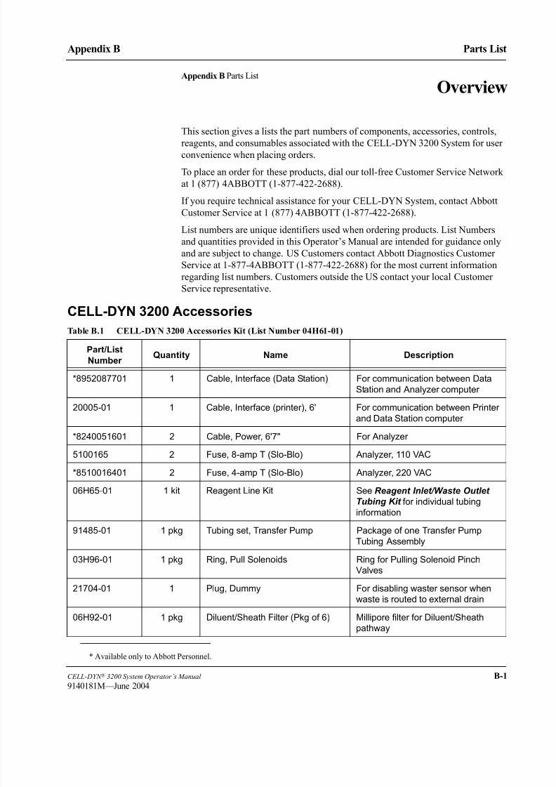
8/21/2019 Equ22-14 CellDyn3200 Op Man
http://slidepdf.com/reader/full/equ22-14-celldyn3200-op-man 679/690
CELL-DYN ® 3200 System Operator’s Manual B-1
9140181M—June 2004
Appendix B Parts List
Appendix B Parts List
Overview
This section gives a lists the part numbers of components, accessories, controls,
reagents, and consumables associated with the CELL-DYN 3200 System for user
convenience when placing orders.
To place an order for these products, dial our toll-free Customer Service Network
at 1 (877) 4ABBOTT (1-877-422-2688).
If you require technical assistance for your CELL-DYN System, contact Abbott
Customer Service at 1 (877) 4ABBOTT (1-877-422-2688).
List numbers are unique identifiers used when ordering products. List Numbers
and quantities provided in this Operator’s Manual are intended for guidance only
and are subject to change. US Customers contact Abbott Diagnostics Customer
Service at 1-877-4ABBOTT (1-877-422-2688) for the most current information
regarding list numbers. Customers outside the US contact your local CustomerService representative.
CELL-DYN 3200 Accessories
Table B.1 CELL-DYN 3200 Accessories Kit (List Number 04H61-01)
Part/List
Number Quantity Name Description
*8952087701 1 Cable, Interface (Data Station) For communication between Data
Station and Analyzer computer
20005-01 1 Cable, Interface (printer), 6' For communication between Printer
and Data Station computer
*8240051601 2 Cable, Power, 6'7" For Analyzer
5100165 2 Fuse, 8-amp T (Slo-Blo) Analyzer, 110 VAC
*8510016401 2 Fuse, 4-amp T (Slo-Blo) Analyzer, 220 VAC
06H65-01 1 kit Reagent Line Kit See Reagent Inlet/Waste Outlet
Tubing Kit for individual tubing
information
91485-01 1 pkg Tubing set, Transfer Pump Package of one Transfer Pump
Tubing Assembly
03H96-01 1 pkg Ring, Pull Solenoids Ring for Pulling Solenoid Pinch
Valves
21704-01 1 Plug, Dummy For disabling waster sensor when
waste is routed to external drain
06H92-01 1 pkg Diluent/Sheath Filter (Pkg of 6) Millipore filter for Diluent/Sheath
pathway
* Available only to Abbott Personnel.

8/21/2019 Equ22-14 CellDyn3200 Op Man
http://slidepdf.com/reader/full/equ22-14-celldyn3200-op-man 680/690
B-2 CELL-DYN ® 3200 System Operator’s Manual
9140181M—June 2004
Parts List
Overview Appendix B
CELL-DYN 3200 Optional Accessories
N/A 1 Paper (printer)
9130556 1 Tubing (600" roll) Tygon Tubing (1/4" ID, 3/8" OD)
N/A 1 Mixing and Handling Inserts
92532-01 1 Serial Loop-Back Device (RS232) For testing the Laboratory
Information System (LIS)
Table B.2 CELL-DYN 3200 Sample Loader Accessories Kit
List Number Quantity Name Comments
04H87-01 1 set Racks, Sample Loader Set of 5 Sample Loader racks pre-
labeled with tube position numbers
and rack number label
Table B.3 CELL-DYN 3200 Optional Accessories
Part/List
Number Quantity Name Description
01H11-01 1 Ink cartridge, Black For use with Canon Bubble Jet
Printer
01H50-01 1 Ink cartridge, Black For use with Epson 850 Printer
01H51-01 1 Ink cartridge, Color For use with Epson 850 Printer
01H52-01 1 Ink cartridge, Cyan For use with Canon Bubble Jet
Printer
01H53-01 1 Ink cartridge, Magenta For use with Canon Bubble Jet
Printer
06H87-02 1 Black Ink cartridge For use with Canon Bubble Jet 4300
Printer
06H87-04 1 Color Ink cartridge For use with Canon Bubble Jet 4300
Printer
8140321601 1 Keyboard Cover, Flexible For use with keyboard ln 07H96-01
(service orders item)
07H96-01 1 Keyboard, PC AT Enhanced PC-AT small footprint keyboard
01J52-01 1 Printer Cartridge, Color For use with Epson 888 printer
01J53-01 1 Printer Cartridge, Black For use with Epson 888 printer
25860-01 1 Label Dispenser, Bar Code Dispenser for Bar Code Label rolls
99650-01 1 Labels, Tube ID Bar Code, 1 roll Tube ID Bar Code Labels (1000
labels per roll)
Table B.1 CELL-DYN 3200 Accessories Kit (List Number 04H61-01) (Continued)
Part/List
Number Quantity Name Description

8/21/2019 Equ22-14 CellDyn3200 Op Man
http://slidepdf.com/reader/full/equ22-14-celldyn3200-op-man 681/690
CELL-DYN ® 3200 System Operator’s Manual B-3
9140181M—June 2004
Appendix B Parts List
99652-01 1 Labels, QC Bar Code QC Bar Code Labels (Numeral 1-
20), in Code 39 (without check digit)
06H62-01 1 Labels, CELL-DYN 3200 Rack Bar
Code, set of 100
Bar Code Labels for Autoloader
Racks (#s 0-99)
06H71-01 1 Specifications, Interface,
CELL-DYN 3200
Description and specifications for
communications between a
Laboratory Information System (LIS)
and the CELL-DYN 3200 System
04H34-01 1 Syringe, 10 mL For dispensing Diluent/Sheath
reagent
07H97-01 1 OKI B4300 Laser Mono Printer (120V)
07H98-01 1 Toner cartridge, Black For use with OKI B4300 Printer
28561-01 1 Syringe, 2.5 mL For dispensing WBC Lyse or HGB
Lyse reagent
28560-01 1 Syringe, 500 µL For injecting diluted sample into
optical flow cell
03B96-02 500/pkg 8 1/2 x 11 Printer Paper
03H99-01 1 Needle, Vent/Aspiration For venting/aspirating samples in
Closed Mode
06H92-01 6 Diluent/Sheath Filter Millipore filter for Diluent/Sheath
pathway
06H60-01 1 Operator’s Manual English Version
06H64-01 1 CELL-DYN 3200 Shear Valve
Center Section
Ceramic Center Section for
CELL-DYN 3200 Blood Shear Valve
07H67-01 5 Cap (small), Reagent line tubing For the 960mL blttle
07H67-02 5 Cap (large), Reagent line tubing For the 3.8 and 20L containers
07H85-02 1 Tube Deflector (brush) For positioning tubes closer to Tube
Sensor
99644-01 1 Enzymatic Cleaner
99624-01 Pre-Printed Tickets
Table B.3 CELL-DYN 3200 Optional Accessories (Continued)
Part/List
Number Quantity Name Description

8/21/2019 Equ22-14 CellDyn3200 Op Man
http://slidepdf.com/reader/full/equ22-14-celldyn3200-op-man 682/690
B-4 CELL-DYN ® 3200 System Operator’s Manual
9140181M—June 2004
Parts List
Overview Appendix B
NOTE: All of the items in the Reagent Inlet/Outlet Tubing Kit are included in the Accessories Kit, but can also
be ordered as a Reagent Line Kit (06H65-01).
Table B.4 CELL-DYN 3200 Controls/Calibrator
List Number Quantity Name Description
01H61-01 1 Calibrator, CELL-DYN HemCal 3.0-mL tube with pierceable cap,
insert, and assay sheets
01H71-01 1 Control, CELL-DYN 26 (tri-level) 3.0-mL Vacutainers with pierceable
cap, insert, and assay sheets
03H41-01 1 Control, CELL-DYN Retic-RITE® 3.0-mL tubes, levels I and II, pierceable
caps, insert, and assay sheet
99120-01 1 Calibrator, CELL-DYN 22 2.5-mL tubes, insert, and assay sheet
93111-01 1 Control, CELL-DYN 22 (tri-level) 2.5-mL tubes, insert, and assay sheet
Table B.5 CELL-DYN 3200 Reagents
List Number Quantity Name Single Container Size Case WeightQTY/ Case
03H78-01 1 Reagent, WBC Lyse 960 mL bottle 1.0 ± 0.2 kg
1/case
03H79-01 1 Reagent, Diluent/Sheath 20-L cubitainer 21.9 ± 0.5 kg
1/case
03H80-02 1 Reagent,
CN free HGB/NOC Lyse
3.8 L cubitainer 4.03 ± .01 kg
1/case
03H40-01 1 Reagent, Reticulocyte 5.0 mL tubes, each tube
containing 3.7 mL of
reagent
Kit of 100
Table B.6 CELL-DYN 3200 Reagent Inlet/Outlet Tubing (List Number 06H65-01)
List Number Quantity Name Comments
*8921205901 1 Tubing, Reagent, Diluent/Sheath Includes reagent container cap,
and sinker
*8921211501 1 Tubing, Reagent, HGB/NOC Lyse Includes reagent container cap,
and sinker, for 1-liter bottle
*8921149401 1 Tubing, Reagent, HGB Lyse Includes reagent container cap,
and sinker, for 4-liter container
*8921210101 1 Tubing, Reagent, WBC Lyse Includes reagent container cap,
and sinker
02H96-01 1 Assy, Waste Line CELL-DYN 3200 Includes reagent container cap,
and sensor
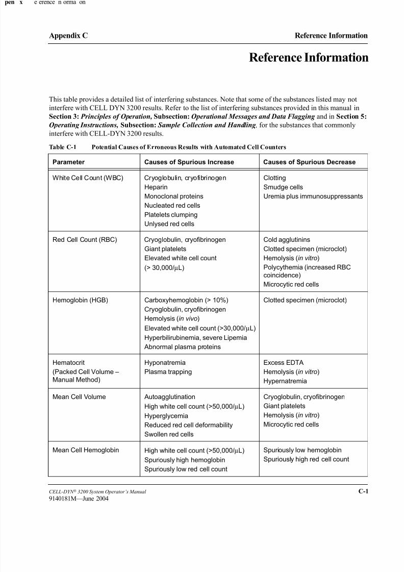
8/21/2019 Equ22-14 CellDyn3200 Op Man
http://slidepdf.com/reader/full/equ22-14-celldyn3200-op-man 683/690
CELL-DYN ® 3200 System Operator’s Manual C-1
9140181M—June 2004
Appendix C Reference Information
Reference Information
This table provides a detailed list of interfering substances. Note that some of the substances listed may notinterfere with CELL DYN 3200 results. Refer to the list of interfering substances provided in this manual in
Section 3: Principles of Operation, Subsection: Operational Messages and Data Flagging and in Section 5:
Operating Instructions, Subsection: Sample Collection and Handling , for the substances that commonly
interfere with CELL-DYN 3200 results.
Table C-1 Potential Causes of Erroneous Results with Automated Cell Counters
Parameter Causes of Spurious Increase Causes of Spurious Decrease
White Cell Count (WBC) Cryoglobulin, cryofibrinogen
Heparin
Monoclonal proteins
Nucleated red cells
Platelets clumping
Unlysed red cells
Clotting
Smudge cells
Uremia plus immunosuppressants
Red Cell Count (RBC) Cryoglobulin, cryofibrinogen
Giant platelets
Elevated white cell count
(> 30,000/µL)
Cold agglutinins
Clotted specimen (microclot)
Hemolysis (in vitro)
Polycythemia (increased RBC
coincidence)
Microcytic red cells
Hemoglobin (HGB) Carboxyhemoglobin (> 10%)Cryoglobulin, cryofibrinogen
Hemolysis (in vivo)
Elevated white cell count (>30,000/µL)
Hyperbilirubinemia, severe Lipemia
Abnormal plasma proteins
Clotted specimen (microclot)
Hematocrit
(Packed Cell Volume –
Manual Method)
Hyponatremia
Plasma trapping
Excess EDTA
Hemolysis (in vitro)
Hypernatremia
Mean Cell Volume Autoagglutination
High white cell count (>50,000/µL)
Hyperglycemia
Reduced red cell deformability
Swollen red cells
Cryoglobulin, cryofibrinogen
Giant platelets
Hemolysis (in vitro)
Microcytic red cells
Mean Cell Hemoglobin High white cell count (>50,000/µL)
Spuriously high hemoglobin
Spuriously low red cell count
Spuriously low hemoglobin
Spuriously high red cell count
x e erence n orma on

8/21/2019 Equ22-14 CellDyn3200 Op Man
http://slidepdf.com/reader/full/equ22-14-celldyn3200-op-man 684/690
C-2 CELL-DYN ® 3200 System Operator’s Manual
9140181M—June 2004
Reference Information
Reference Information Appendix C
Source:
• Cornbleet J. Spurious Results from Automated Hematology Cell Counters. Laboratory Medicine 1983;
14:509-514.
Mean Cell Hemoglobin
Concentration
Autoagglutination
Clotting
Hemolysis (in vivo and in vitro)
Supriously high hemoglobin
Spuriously low hematocrit
High white cell count (>50,000/µL)
Spuriously low hemoglobin
Spuriously high red cell count
Platelets (PLT) Cryoglobulin, cryofibrinogen
Hemolysis (in vivo and in vitro)
Microcytic red cells
Red cell inclusions
White cell fragments
Clotting
Giant platelets
Heparin
Platelet clumping
Platelet satellitosis
Table C-1 Potential Causes of Erroneous Results with Automated Cell Counters (Continued)
Parameter Causes of Spurious Increase Causes of Spurious Decrease

8/21/2019 Equ22-14 CellDyn3200 Op Man
http://slidepdf.com/reader/full/equ22-14-celldyn3200-op-man 685/690
CELL-DYN ® 3200 System Operator’s Manual Index-1
9140181M—June 2004
Index
Index
AAbbott representative 10-10, 10-11
ACCEPT SPECIMEN 14-38
Accessory Kit 2-2
Accuracy 4-13
Aerosol Filter 1-12
Alerts 5-97
Analyzer 1-1, 1-2, 1-5, 1-6, 1-9, 1-12, 1-17,
5-66, 5-69, 5-97, 9-1, 9-4, 9-47, 10-24
Analyzer Components 1-6
Analyzer Disable 9-5, 9-6, 9-20, 9-34, 9-36,
9-40, 9-46, 9-47, 9-50
Analyzer Enable 9-6
Analyzer Faults 13-12
Analyzer Serial Number 1-16
Anticoagulant 5-83
Aspiration 1-2, 1-9, 1-10, 5-84, 13-13, 13-21,
13-23
Aspiration Incomplete 10-27
Aspiration Needle Cleaning 9-15
Aspiration Needle Replacement 9-50
Aspiration Open sampler 1-9aspiration probe - interior cleaning 9-33
Aspiration Probe Replacement 9-48
Aspiration Tower 1-12
Aspiration Volume 3-1
Aspiration Volumes 4-5
Auto-Cal Menu 6-21
Auto-Cal Methodology 6-19
Auto-Cal reference values 6-26, 6-30
Auto-Cal Screen 6-21, 6-26, 6-29
Auto-Calibrate screen 6-17
Auto-Clean 9-7Auto-Clean cycle 5-99
Auto-Clean—Open Mode 9-13
Automatic Shutdown 5-99
BBackground 4-9
Background Counts 1-26, 4-9, 5-74, 6-10,
9-14, 9-15, 9-16, 9-24, 9-33, 9-35, 9-45,
9-47, 9-49, 9-52, 9-54, 10-26
Troubleshooting 10-25
Background Soft Key 14-58
Bar Code 5-59, 5-91, 5-115, 5-118, 13-1
Bar Code Format 4-6
Bar Code Label 13-6, 13-7
Bar Code Label Placement 13-6
Bar Code Reader 1-13, 1-24, 13-6
Bias 6-33
Bubble Traps 1-12
Bulletin Line 5-67, 5-69, 5-128, 5-129, 10-1
C
Calibration 6-5, 6-10, 6-14, 6-52, 6-54, 10-23
Menu Flowchart 5-9
Calibration - Detemining Parameters, Open
Mode 6-39, 6-45
Calibration - Determining Reference Values
6-20
Calibration - Enter Factor Method 6-33
Calibration - Entering New Factors, Open
Mode 6-41, 6-47
Calibration - Fresh Whole Blood 6-5
Calibration - Post-Calibration Procedures 6-55
Calibration - Pre-Calibration Checklist 6-9
Calibration - pre-calibration procedures 6-7
Calibration - Reset 6-15
Calibration - Restore Factors 6-15Calibration Criteria 6-53, 6-54
Calibration frequency 6-4
Calibration guidelines 6-7

8/21/2019 Equ22-14 CellDyn3200 Op Man
http://slidepdf.com/reader/full/equ22-14-celldyn3200-op-man 686/690
Index-2 CELL-DYN ® 3200 System Operator’s Manual
9140181M—June 2004
Index
Calibration Log 6-16
Calibration Logbook 6-5
Calibration logbook 6-5
Calibration Materials 5-93, 6-5
Calibration Menu 6-13, 6-15
Calibration overview 6-1Calibration Procedures
Calibration Guidelines
General Information 6-3
Overview 6-1
Calibration screen 6-15
calibrator 6-1
Calibrator Requirements 6-8
Carryover 4-9
CELL-DYN control material 11-15
CELL-DYN Retic-RITE® 14-65
Check Digit 5-41Check digits A-5
Chemical Hazards 8-4
Clean Needle 5-99
cleaning instrument 9-7
CLEAR FAULT 14-42
Clear Fault 10-8
Clear Fault Soft Key 14-49
Clog 9-9
clog 9-57
Closed Mode 1-12
Closed Mode QC Procedure 5-89
Closed Sample Needle Interior Cleaning 9-36
Closed Sampler aspiration 5-95
commercial controls 11-1
Computer 1-20
consumables 1-27
control material 11-15
Customer Service
phone numbers i
Customer Service Center 10-24
CV% 14-36
D
Daily Shutdown 9-7
Daily Shutdown cycle 5-99
Daily Shutdown Procedure 5-99
Data Flagging 14-68Data Invalidating Alerts 14-69
Data Log 5-65, 5-72, 5-73, 5-74, 5-103, 5-
109, 5-115, 5-121, 5-125, 5-127, 5-130,
5-132, 5-134, 5-135, 10-26
Menu Flowchart 5-7
Data Log - Customize Display 5-132, 5-139
Data Log - Customize Printout 5-135, 5-141
Data Log - Customize Report 5-128
Data Log - Display Specimen 5-128
Data Log - Edit Specimen 5-128
Data Log - Edit Specimen ID 5-127Data Log - Print Report 5-129
Data Log - record display 5-143
Data Log Codes 5-137
Data Log Menu 5-126
Data Log Printout 5-125, 5-126, 5-135, 5-136
Data Log screen 5-129
Data Log Scrolling 5-125
Data Log scrolling 5-143
DATA LOG SEARCH Screen 5-129
Data Log Set Up 5-138
Data Module 1-5, 1-20Data Module faults 13-12
Data Station 1-19, 1-22, 12-5
Data Storage 1-20
decontamination procedures 9-12
Delete Specimen 11-11
DIAGNOSTICS MENU - fifth (CS) 10-19
DIAGNOSTICS MENU - fifth (SL) 10-22
DIAGNOSTICS MENU - first 10-4
DIAGNOSTICS MENU - fourth 10-18
DIAGNOSTICS MENU - second 10-10
DIAGNOSTICS MENU - third 10-16Diagnostics Menu Flowchart 5-10, 5-11
Differential 5-77
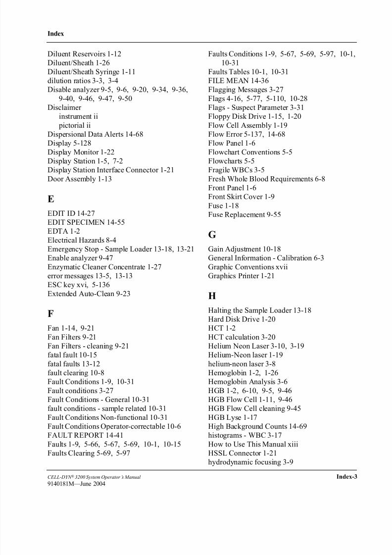
8/21/2019 Equ22-14 CellDyn3200 Op Man
http://slidepdf.com/reader/full/equ22-14-celldyn3200-op-man 687/690
CELL-DYN ® 3200 System Operator’s Manual Index-3
9140181M—June 2004
Index
Diluent Reservoirs 1-12
Diluent/Sheath 1-26
Diluent/Sheath Syringe 1-11
dilution ratios 3-3, 3-4
Disable analyzer 9-5, 9-6, 9-20, 9-34, 9-36,
9-40, 9-46, 9-47, 9-50Disclaimer
instrument ii
pictorial ii
Dispersional Data Alerts 14-68
Display 5-128
Display Monitor 1-22
Display Station 1-5, 7-2
Display Station Interface Connector 1-21
Door Assembly 1-13
E
EDIT ID 14-27
EDIT SPECIMEN 14-55
EDTA 1-2
Electrical Hazards 8-4
Emergency Stop - Sample Loader 13-18, 13-21
Enable analyzer 9-47
Enzymatic Cleaner Concentrate 1-27
error messages 13-5, 13-13
ESC key xvi, 5-136
Extended Auto-Clean 9-23
F
Fan 1-14, 9-21
Fan Filters 9-21
Fan Filters - cleaning 9-21
fatal fault 10-15
fatal faults 13-12
fault clearing 10-8
Fault Conditions 1-9, 10-31
Fault conditions 3-27Fault Conditions - General 10-31
fault conditions - sample related 10-31
Fault Conditions Non-functional 10-31
Fault Conditions Operator-correctable 10-6
FAULT REPORT 14-41
Faults 1-9, 5-66, 5-67, 5-69, 10-1, 10-15
Faults Clearing 5-69, 5-97
Faults Conditions 1-9, 5-67, 5-69, 5-97, 10-1,
10-31
Faults Tables 10-1, 10-31
FILE MEAN 14-36
Flagging Messages 3-27
Flags 4-16, 5-77, 5-110, 10-28Flags - Suspect Parameter 3-31
Floppy Disk Drive 1-15, 1-20
Flow Cell Assembly 1-19
Flow Error 5-137, 14-68
Flow Panel 1-6
Flowchart Conventions 5-5
Flowcharts 5-5
Fragile WBCs 3-5
Fresh Whole Blood Requirements 6-8
Front Panel 1-6
Front Skirt Cover 1-9Fuse 1-18
Fuse Replacement 9-55
G
Gain Adjustment 10-18
General Information - Calibration 6-3
Graphic Conventions xvii
Graphics Printer 1-21
H
Halting the Sample Loader 13-18
Hard Disk Drive 1-20
HCT 1-2
HCT calculation 3-20
Helium Neon Laser 3-10, 3-19
Helium-Neon laser 1-19
helium-neon laser 3-8
Hemoglobin 1-2, 1-26
Hemoglobin Analysis 3-6
HGB 1-2, 6-10, 9-5, 9-46HGB Flow Cell 1-11, 9-46
HGB Flow Cell cleaning 9-45
HGB Lyse 1-17
High Background Counts 14-69
histograms - WBC 3-17
How to Use This Manual xiii
HSSL Connector 1-21
hydrodynamic focusing 3-9

8/21/2019 Equ22-14 CellDyn3200 Op Man
http://slidepdf.com/reader/full/equ22-14-celldyn3200-op-man 688/690
Index-4 CELL-DYN ® 3200 System Operator’s Manual
9140181K—July 2002
Index
I
Imprecise or Inaccurate Data -
troubleshooting 10-27
Incomplete Aspiration 5-98, 10-27
Incomplete aspiration 5-137incubate 14-63
incubation time limit 14-63
Initialization 10-3, 10-6, 10-11, 10-15
initialization 5-60
Instrument Alert Conditions 14-68
Intended Use
CELL-DYN 1700 i
Interfering Substances 5-84
Reticulocytes 14-60
Intermediate-term Shutdown 5-100
K
keyboard
text conventions xvi
L
Latex 6-5
Left Front Cover 1-8
LEVEY-JENNINGS 14-37
Levey-Jennings 11-9, 14-34Light scatter 1-26
Line Frequency 1-18
Linearity 4-12
LIS Connector 1-21
load side - Sample Loader 13-14
Location Requirements 7-1
logbook - calibration 6-5
LOT NUMBER 14-28
Lot Number 14-21
MMain Menu
Flowchart 5-5
Main menu screen 5-78, 9-3, 9-14
main power cord 1-18
Main Power Switch 1-16
main power switch 5-59
Maintenance - nonscheduled 9-29
Maintenance Log 10-25
Maintenance Procedures - daily 9-13
Maintenance Procedures - monthly 9-21
Maintenance Procedures - semiannual 9-27
Maintenance Procedures - weekly 9-19Maintenance Schedule 9-10
Manual Organization xiii
MCH 1-2, 11-23
MCH calculation 3-21
MCHC 1-3, 11-23
MCHC calculation 3-21
MCV 11-23
MCV calculation 3-20
Means and Limits 14-19
MEANS/LIMITS 14-18
mechanical safety 8-5Membrane Keypad 1-21
Membrane Keypad Interface Connector 1-21
Mixing Station 1-24
MOVE SPECIMEN 14-39
Move Specimen 11-12
MOVE TO FILE 14-39
MPV 1-3
MPV calculation 3-22
N N 14-36
NCCLS 14-3
Needle Cleaning Block 1-12
Needle Exterior Cleaning 9-19
New Methylene Blue N 14-3
Nonscheduled Maintenance - frequency 9-29
Nonscheduled Maintenance - procedures 9-31
Normally Closed Valves 1-12, 2-6
Nucleated Optical Count 3-5
O
OKIDATA dot matrix printer 2-13
Open Mode Probe 1-9
Open Sample Aspiration Probe 1-9, 1-11, 5-94
Open Sample Aspiration Probe Description 1-9
Open Sample Probe - Unclogging 9-36
Open Sampler 5-66
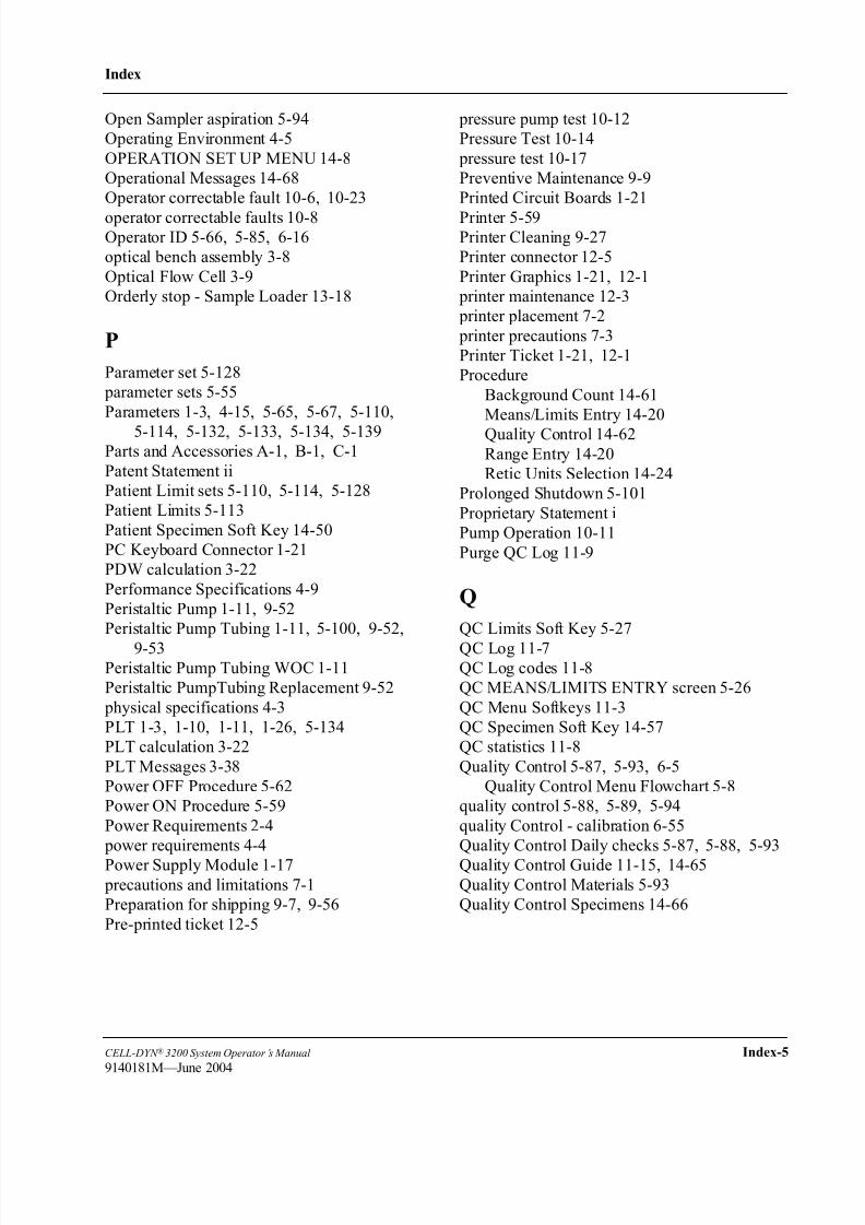
8/21/2019 Equ22-14 CellDyn3200 Op Man
http://slidepdf.com/reader/full/equ22-14-celldyn3200-op-man 689/690
CELL-DYN ® 3200 System Operator’s Manual Index-5
9140181M—June 2004
Index
Open Sampler aspiration 5-94
Operating Environment 4-5
OPERATION SET UP MENU 14-8
Operational Messages 14-68
Operator correctable fault 10-6, 10-23
operator correctable faults 10-8Operator ID 5-66, 5-85, 6-16
optical bench assembly 3-8
Optical Flow Cell 3-9
Orderly stop - Sample Loader 13-18
P
Parameter set 5-128
parameter sets 5-55
Parameters 1-3, 4-15, 5-65, 5-67, 5-110,
5-114, 5-132, 5-133, 5-134, 5-139Parts and Accessories A-1, B-1, C-1
Patent Statement ii
Patient Limit sets 5-110, 5-114, 5-128
Patient Limits 5-113
Patient Specimen Soft Key 14-50
PC Keyboard Connector 1-21
PDW calculation 3-22
Performance Specifications 4-9
Peristaltic Pump 1-11, 9-52
Peristaltic Pump Tubing 1-11, 5-100, 9-52,
9-53Peristaltic Pump Tubing WOC 1-11
Peristaltic PumpTubing Replacement 9-52
physical specifications 4-3
PLT 1-3, 1-10, 1-11, 1-26, 5-134
PLT calculation 3-22
PLT Messages 3-38
Power OFF Procedure 5-62
Power ON Procedure 5-59
Power Requirements 2-4
power requirements 4-4
Power Supply Module 1-17
precautions and limitations 7-1
Preparation for shipping 9-7, 9-56
Pre-printed ticket 12-5
pressure pump test 10-12
Pressure Test 10-14
pressure test 10-17
Preventive Maintenance 9-9
Printed Circuit Boards 1-21
Printer 5-59Printer Cleaning 9-27
Printer connector 12-5
Printer Graphics 1-21, 12-1
printer maintenance 12-3
printer placement 7-2
printer precautions 7-3
Printer Ticket 1-21, 12-1
Procedure
Background Count 14-61
Means/Limits Entry 14-20
Quality Control 14-62Range Entry 14-20
Retic Units Selection 14-24
Prolonged Shutdown 5-101
Proprietary Statement i
Pump Operation 10-11
Purge QC Log 11-9
Q
QC Limits Soft Key 5-27
QC Log 11-7QC Log codes 11-8
QC MEANS/LIMITS ENTRY screen 5-26
QC Menu Softkeys 11-3
QC Specimen Soft Key 14-57
QC statistics 11-8
Quality Control 5-87, 5-93, 6-5
Quality Control Menu Flowchart 5-8
quality control 5-88, 5-89, 5-94
quality Control - calibration 6-55
Quality Control Daily checks 5-87, 5-88, 5-93
Quality Control Guide 11-15, 14-65
Quality Control Materials 5-93
Quality Control Specimens 14-66

8/21/2019 Equ22-14 CellDyn3200 Op Man
http://slidepdf.com/reader/full/equ22-14-celldyn3200-op-man 690/690
Index
R
Rack Movement - Sample Loader 13-14
Rack starting position - Sample Loader 13-14
RANGE ENTRY 14-18
Range Entry 14-19Raw data summary 10-9, 10-28
RBC 1-2, 1-10, 1-12, 1-26, 5-77, 5-79, 5-134
RBC Count 3-20
RBC Messages 3-38
RBC/PLT Analysis 3-6
RBC/PLT Mixing Chamber 1-11
RDW calculation 3-21
Ready 1-9, 1-17, 5-66, 5-69
reagent handling 7-3
reagent inlet tubing 2-5
Reagent Line Cleaning 9-48reagent residue 9-57
reagent storage 7-3
Reagent System 1-25
Reagents 1-25, 4-15, 6-5, 6-10, 9-3, 9-7,
9-31, 10-24
reagents 7-2
Reagents Container replacement 10-26
Reagents Troubleshooting 10-25, 10-26
Re-initializing Sample Loader 13-18
REJECT SPECIMEN 14-38
Reject/Accept Specimen 11-10Reliability i
Reset Loader 13-12
Resistant RBCs 3-5
RESTART menu - Sample Loader 13-11
Restarting the Loader 13-11
Resume Loader 13-11
RETIC CNT GRAPH 14-42
RETIC CNT RATE SUMM 14-41
RETIC DATA LOG 14-25, 14-28, 14-30,
14-33
Retic Data Log Codes 14-27RETIC DISPLAY SPECIMEN 14-25
RETIC MAIN menu 14-12, 14-43
Retic Main Soft Key 14-58
RETIC PATIENT LIMITS 14-15
RETIC PT LIMITS 14-15
Retic QC Limit 14-18
RETIC QC SET UP 14-17
Retic Run Menu 14-6
Retic Run Menu Flowchart 14-4
RETIC RUN RESULT screen 14-53, 14-54RETIC RUN screen 14-49, 14-59
Reticulocyte Package 14-3
Reticulocyte QC files 14-17
Reticulocyte Reagent 14-65
reticulocyte reagent 14-61
Reticulocyte Sequence Number 14-12, 14-35
Reticulocyte Specimens 14-59
Reticulocytes 14-3
Revision Status xviii
Right Front Cover 1-8
Run Cycle Times 4-5Run Menu
Flowchart 5-7
Running Patient Samples 14-63
running samples - CS closed mode 5-96
running samples - SL closed mode 5-91
Running Samples - SL open mode 5-89
running samples CS open mode 5-94
Running Specimens 14-60
SSafety Cover - Sample Loader 13-21
Sample 5-65, 5-67, 5-68, 5-73, 5-77, 5-83,
5-88, 5-89, 5-94, 5-103, 5-114, 9-19,
9-23, 9-52, 10-23, 13-1
Sample Analysis Cycle 3-3
sample aspiration modes 3-1
Sample Feed Nozzle 1-19
Sample ID 5-85
Sample Identification 5-70, 5-103, 13-17
Sample Loader 1-1, 1-5, 1-17, 4-19, 5-59,
5-88, 5-99, 13-7
Sample Loader - cleaning 9-19
Sample Loader - emergency stops 13-18
Sample Loader - orderly stops 13-18
Sample Loader - re-initialize 13-18