equipment : neo 1973 trade name : fic model no. : gta01bv4...
TRANSCRIPT

FD721310
Equipment : Neo 1973 Trade Name : FIC Model No. : GTA01BV4 FCC ID : EUNGTA01BV4 Applicant : FIC (First International Computer, Inc.)
No. 300, Yang Guang, NeiHu, Taipei, Taiwan, 114
The measurements shown in this test report were made in accordance with the procedures given in ANSI C63.4 - 2003 and the energy emitted by this equipment was passed FCC Part 15 B in both radiated and conducted emission class B limits. Testing was carried out on Jun. 29, 2007 at SPORTON International Inc. LAB. Roy Wu Deputy Manager

TEST REPORT Report No. : FD721310
SPORTON International Inc.TEL : 886-2-2696-2468FAX : 886-2-2696-2255
Report Version: Rev. 01
FCC TEST REPORT
According to
47 CFR Part 15 Subpart B
Equipment : Neo 1973
Trade Name : FIC
Model No. : GTA01BV4
FCC ID : EUNGTA01BV4
Filing Type : Declaration of Conformity
Applicant : FIC (First International Computer, Inc.)
No. 300, Yang Guang, NeiHu, Taipei, Taiwan, 114
The test result refers exclusively to the test presented test model / sample. Without written approval of SPORTON International Inc., the test report shall not be
reproduced except in full. Certificate or Test Report must not be used by the applicant to claim the product in this test
report endorsement by NVLAP or any agency of U.S. government. Report Version: Rev. 01
SPORTON International Inc. 6F, No.106, Sec. 1, Hsin Tai Wu Rd., Hsi Chih, Taipei Hsien, Taiwan, R.O.C.

TEST REPORT Report No. : FD721310
SPORTON International Inc. Page No. : i TEL : 886-2-2696-2468 Report Issued Date : Jul. 03, 2007 FAX : 886-2-2696-2255 Report Version : Rev. 01 FCC ID : EUNGTA01BV4
Table of Contents
History of this test report....................................................................................................................................ii CERTIFICATE OF COMPLIANCE........................................................................................................................1 1. General Description of Equipment under Test.............................................................................................2
1.1 Applicant..........................................................................................................................................................................................2 1.2 Manufacturer ...................................................................................................................................................................................2 1.3 Basic Description of Equipment under Test ....................................................................................................................................2 1.4 Feature of Equipment under Test ...................................................................................................................................................3
2. Test Configuration of Equipment under Test ...............................................................................................4 2.1 Test Manner ....................................................................................................................................................................................4 2.2 Description of Test System .............................................................................................................................................................4 2.3 Connection Diagram of Test System ..............................................................................................................................................4
3. Test Software ...................................................................................................................................................6 4. General Information of Test............................................................................................................................7
4.1 Test Facility .....................................................................................................................................................................................7 4.2 Test Voltage ....................................................................................................................................................................................7 4.3 Standard for Methods of Measurement...........................................................................................................................................7 4.4 Test in Compliance with ..................................................................................................................................................................7 4.5 Frequency Range Investigated .......................................................................................................................................................7 4.6 Test Distance ..................................................................................................................................................................................7
5. Test of Conducted Powerline .........................................................................................................................8 5.1 Major Measuring Instruments..........................................................................................................................................................8 5.2 Test Procedures ..............................................................................................................................................................................8 5.3 Typical Test Setup Layout of Conducted Powerline .......................................................................................................................9 5.4 Test Result of AC Powerline Conducted Emission .......................................................................................................................10 5.5 Photographs of Conducted Powerline Test Configuration ............................................................................................................14
6. Test of Radiated Emission............................................................................................................................17 6.1 Major Measuring Instruments........................................................................................................................................................17 6.2 Test Procedures ............................................................................................................................................................................18 6.3 Typical Test Setup Layout of Radiated Emission..........................................................................................................................19 6.4 Test Result of Radiated Emission .................................................................................................................................................20 6.5 Photographs of Radiated Emission Test Configuration ................................................................................................................26
7. List of Measuring Equipment Used .............................................................................................................28 8. Uncertainty of Evaluation .............................................................................................................................29 9. Certificate of NVLAP Accreditation .............................................................................................................31 Appendix A. Photographs of EUT

TEST REPORT Report No. : FD721310
SPORTON International Inc. Page No. : ii TEL : 886-2-2696-2468 Report Issued Date : Jul. 03, 2007 FAX : 886-2-2696-2255 Report Version : Rev. 01 FCC ID : EUNGTA01BV4
History of this test report
Report Issue Date: Jul. 03, 2007
Report No. Description

TEST REPORT Report No. : FD721310
SPORTON International Inc. Page No. : 1 of 31 TEL : 886-2-2696-2468 Report Issued Date : Jul. 03, 2007 FAX : 886-2-2696-2255 Report Version : Rev. 01 FCC ID : EUNGTA01BV4
Certificate No. : FD721310
CERTIFICATE OF COMPLIANCE
according to
47 CFR Part 15 Subpart B
Equipment : Neo 1973 Trade Name : FIC Model No. : GTA01BV4 FCC ID : EUNGTA01BV4 Filing Type : Declaration of Conformity Applicant : FIC (First International Computer, Inc.)
No. 300, Yang Guang, NeiHu, Taipei, Taiwan, 114
I HEREBY CERTIFY THAT:
The measurements shown in this test report were made in accordance with the procedures given in ANSI C63.4 - 2003 and the energy emitted by this equipment was passed FCC Part 15 B in both radiated and conducted emission class B limits. Testing was carried out on Jun. 29, 2007 at SPORTON International Inc. LAB.
Roy Wu Deputy Manager
SPORTON International Inc.
6F, No.106, Sec. 1, Hsin Tai Wu Rd., Hsi Chih, Taipei Hsien, Taiwan, R.O.C.

TEST REPORT Report No. : FD721310
SPORTON International Inc. Page No. : 2 of 31 TEL : 886-2-2696-2468 Report Issued Date : Jul. 03, 2007 FAX : 886-2-2696-2255 Report Version : Rev. 01 FCC ID : EUNGTA01BV4
1. General Description of Equipment under Test
1.1 Applicant FIC (First International Computer, Inc.) No. 300, Yang Guang, NeiHu, Taipei, Taiwan, 114
1.2 Manufacturer FIC (First International Computer, Inc.) No. 300, Yang Guang, NeiHu, Taipei, Taiwan, 114
1.3 Basic Description of Equipment under Test Equipment : Neo 1973 Trade Name : FIC Model No. : GTA01BV4 FCC ID : EUNGTA01BV4 Power Supply Type : Switching, From battery 3.7V AC Power Cord : AC120V, Wall-mount, 1.8 meter, 2 pin Adapter : SEMDICAR, TC-FU-USB Battery : FIC, GTC-01 / GTA-01 Earphone : SEMDITECH, HP-GTA01-MP3JS-G

TEST REPORT Report No. : FD721310
SPORTON International Inc. Page No. : 3 of 31 TEL : 886-2-2696-2468 Report Issued Date : Jul. 03, 2007 FAX : 886-2-2696-2255 Report Version : Rev. 01 FCC ID : EUNGTA01BV4
1.4 Feature of Equipment under Test
Product Feature & Specification
1. DUT Type Neo 1973
2. Trade Name FIC
3. Model Name GTA01BV4
4 Tx Frequency PCS1900 : 1850 ~1910 MHz Bluetooth : 2400~2483.5 MHz
5 Rx Frequency PCS1900 : 1930 ~ 1990 MHz Bluetooth : 2400~2483.5 MHz
6 Number of Channels : Bluetooth : 79
7 Carrier Frequency of Each Channel : Bluetooth : 2402+n*1 MHz; n=0~78
8 Type of Modulation : GSM / GPRS : GMSK Bluetooth : GFSK
9 HW Version : A4
10 SW Version : OpenMoko.GTA01.e.w.v.00.21
11 Antenna Type :
GSM : Tri-band Monopole Antenna GPS (Internal) : Active Patch Antenna GPS (External) : Active Patch Antenna Bluetooth : PiFA Antenna
12 Antenna Connector :
GSM : Coaxial Connector GPS (Internal) : Coaxial Connector GPS (External) : MMCX Connector Bluetooth : N/A
13 Antenna Gain :
GSM : 0.07 dBi GPS (Internal) : 0.5 dBi GPS (External) : 5 dBi Bluetooth : -4.84 dBi
4. Maximum Output Power PCS1900 : 30.93 dBm Bluetooth : 1.85 dBm
5. DUT Stage Production Unit
6. Application Type DoC

TEST REPORT Report No. : FD721310
SPORTON International Inc. Page No. : 4 of 31 TEL : 886-2-2696-2468 Report Issued Date : Jul. 03, 2007 FAX : 886-2-2696-2255 Report Version : Rev. 01 FCC ID : EUNGTA01BV4
2. Test Configuration of Equipment under Test
2.1 Test Manner a. The EUT has been setup pursuant to ANSI C63.4-2003 and configuration operated in a manner which
tended to maximize its emission characteristics in a typical application. b. The complete test system refers to 2.2 for EMI test. c. The following test modes were tested for conducted emission test:
Mode 1: PCS1900 Idle Mode + BT Idle + GPS Rx + Earphone + Adapter + MP3 Mode 2: PCS1900 Idle Mode + BT Idle + GPS Rx + Earphone + USB Link + MP3
d. The following test modes were tested for radiated emission test: Mode 1: PCS1900 Idle Mode + BT Idle + GPS Rx + Earphone + Adapter + MP3 Mode 2: PCS1900 Idle Mode + BT Idle + GPS Rx + Earphone + USB Link + MP3
e. Frequency range investigated: conduction 150 kHz to 30 MHz, radiation 30 MHz to 13 GHz.
2.2 Description of Test System Item Asset Model Name FCC ID Power Cord 1. Base Station (R&S) CMU 200 N/A N/A 2. GPS Station (T&E) GP-50 N/A N/A 3. WLAN AP (SMC) SMC-100 N/A N/A 4. Notebook (DELL) D400 E2K24GBRL N/A 5. Earphone (Sampo) EK-Y652CS N/A N/A 6. Notbook (Sony) PCG-6LDP R33021 N/A
2.3 Connection Diagram of Test System
Mode 1

TEST REPORT Report No. : FD721310
SPORTON International Inc. Page No. : 5 of 31 TEL : 886-2-2696-2468 Report Issued Date : Jul. 03, 2007 FAX : 886-2-2696-2255 Report Version : Rev. 01 FCC ID : EUNGTA01BV4
Mode 2

TEST REPORT Report No. : FD721310
SPORTON International Inc. Page No. : 6 of 31 TEL : 886-2-2696-2468 Report Issued Date : Jul. 03, 2007 FAX : 886-2-2696-2255 Report Version : Rev. 01 FCC ID : EUNGTA01BV4
3. Test Software The EUT is in PCS1900 Idle mode controlled by Base Station Simulator.

TEST REPORT Report No. : FD721310
SPORTON International Inc. Page No. : 7 of 31 TEL : 886-2-2696-2468 Report Issued Date : Jul. 03, 2007 FAX : 886-2-2696-2255 Report Version : Rev. 01 FCC ID : EUNGTA01BV4
4. General Information of Test
4.1 Test Facility
Test Site Location : No. 52, Hwa Ya 1st Rd., Hwa Ya Technology Park, Kwei-Shan Hsiang, Tao Yuan Hsien, Taiwan, R.O.C. TEL : 886-3-327-3456 FAX : 886-3-318-0055
Test Site No. : CO04-HY, 03CH06-HY
4.2 Test Voltage
120V / 60Hz
4.3 Standard for Methods of Measurement
ANSI C63.4-2003
4.4 Test in Compliance with
FCC Part 15 Subpart B
4.5 Frequency Range Investigated
a. Conduction: from 150 kHz to 30 MHz b. Radiation: from 30 MHz to 13000MHz
4.6 Test Distance
The test distance of radiated emission from antenna to EUT is 3m.

TEST REPORT Report No. : FD721310
SPORTON International Inc. Page No. : 8 of 31 TEL : 886-2-2696-2468 Report Issued Date : Jul. 03, 2007 FAX : 886-2-2696-2255 Report Version : Rev. 01 FCC ID : EUNGTA01BV4
5. Test of Conducted Powerline
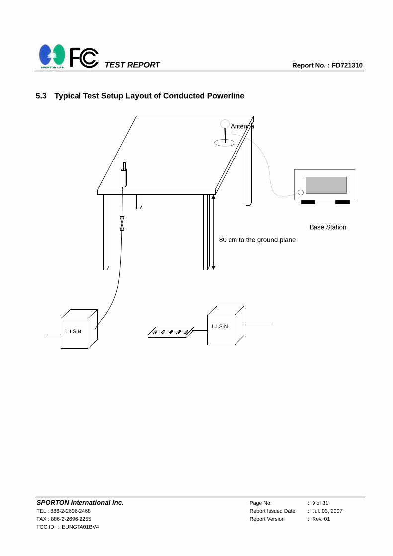
Conducted Emissions were measured from 150 kHz to 30 MHz with a bandwidth of 9 kHz and return leads
of the EUT according to the methods defined in ANSI C63.4-2003 Section 3.1. The EUT was placed on a
nonmetallic stand in a shielded room 0.8 meters above the ground plane as shown in section 5.3. The
interface cables and equipment positioning were varied within limits of reasonable applications to determine
the position produced maximum conducted emissions.
5.1 Major Measuring Instruments As described in Chapter 7.
5.2 Test Procedures
a. The EUT was placed 0.4 meter from the conducting wall of the shielding room was kept at least 80
centimeters from any other grounded conducting surface.
b. Connect EUT to the power mains through a line impedance stabilization network (LISN).
c. All the support units are connecting to the other LISN.
d. The LISN provides 50 ohm coupling impedance for the measuring instrument.
e. The FCC states that a 50 ohm, 50 microhenry LISN should be used.
f. Both sides of AC line were checked for maximum conducted interference.
g. The frequency range from 150 kHz to 30 MHz was searched.
h. Set the test-receiver system to Peak Detect Function and specified bandwidth with Maximum Hold
Mode.
TEST REPORT Report No. : FD721310
SPORTON International Inc. Page No. : 9 of 31 TEL : 886-2-2696-2468 Report Issued Date : Jul. 03, 2007 FAX : 886-2-2696-2255 Report Version : Rev. 01 FCC ID : EUNGTA01BV4
5.3 Typical Test Setup Layout of Conducted Powerline
Base Station
80 cm to the ground plane
Antenna
L.I.S.N L.I.S.N

TEST REPORT Report No. : FD721310
SPORTON International Inc. Page No. : 10 of 31 TEL : 886-2-2696-2468 Report Issued Date : Jul. 03, 2007 FAX : 886-2-2696-2255 Report Version : Rev. 01 FCC ID : EUNGTA01BV4
5.4 Test Result of AC Powerline Conducted Emission
5.4.1 Test Mode: Mode 1
Frequency Range of Test: from 0.15 MHz to 30 MHz Temperature: 25°C Relative Humidity: 58% Test Engineer: Peter All emissions not reported here are more than 10 dB below the prescribed limit. ■ The test that passed at the minimum margin was marked by a frame in the following data

TEST REPORT Report No. : FD721310
SPORTON International Inc. Page No. : 11 of 31 TEL : 886-2-2696-2468 Report Issued Date : Jul. 03, 2007 FAX : 886-2-2696-2255 Report Version : Rev. 01 FCC ID : EUNGTA01BV4

TEST REPORT Report No. : FD721310
SPORTON International Inc. Page No. : 12 of 31 TEL : 886-2-2696-2468 Report Issued Date : Jul. 03, 2007 FAX : 886-2-2696-2255 Report Version : Rev. 01 FCC ID : EUNGTA01BV4
5.4.2 Test Mode: Mode 2
Frequency Range of Test: from 0.15 MHz to 30 MHz Temperature: 25°C Relative Humidity: 58% Test Engineer: Peter All emissions not reported here are more than 10 dB below the prescribed limit. ■ The test that passed at the minimum margin was marked by a frame in the following data

TEST REPORT Report No. : FD721310
SPORTON International Inc. Page No. : 13 of 31 TEL : 886-2-2696-2468 Report Issued Date : Jul. 03, 2007 FAX : 886-2-2696-2255 Report Version : Rev. 01 FCC ID : EUNGTA01BV4

TEST REPORT Report No. : FD721310
SPORTON International Inc. Page No. : 14 of 31 TEL : 886-2-2696-2468 Report Issued Date : Jul. 03, 2007 FAX : 886-2-2696-2255 Report Version : Rev. 01 FCC ID : EUNGTA01BV4
5.5 Photographs of Conducted Powerline Test Configuration Mode 1
Front View
Rear View

TEST REPORT Report No. : FD721310
SPORTON International Inc. Page No. : 15 of 31 TEL : 886-2-2696-2468 Report Issued Date : Jul. 03, 2007 FAX : 886-2-2696-2255 Report Version : Rev. 01 FCC ID : EUNGTA01BV4
Side View
Mode 2
Front View

TEST REPORT Report No. : FD721310
SPORTON International Inc. Page No. : 16 of 31 TEL : 886-2-2696-2468 Report Issued Date : Jul. 03, 2007 FAX : 886-2-2696-2255 Report Version : Rev. 01 FCC ID : EUNGTA01BV4
Rear View
Side View

TEST REPORT Report No. : FD721310
SPORTON International Inc. Page No. : 17 of 31 TEL : 886-2-2696-2468 Report Issued Date : Jul. 03, 2007 FAX : 886-2-2696-2255 Report Version : Rev. 01 FCC ID : EUNGTA01BV4
6. Test of Radiated Emission
Radiated emissions from 30 MHz to 13 GHz were measured with a bandwidth of 120 kHz and 1MHz
according to the methods defines in ANSI C63.4-2003. The EUT was placed on a nonmetallic stand, 0.8
meter above the ground plane, as shown in section 6.3. The interface cables and equipment positions were
varied within limits of reasonable applications to determine the positions producing maximum radiated
emissions.
6.1 Major Measuring Instruments As described in Chapter 7.

TEST REPORT Report No. : FD721310
SPORTON International Inc. Page No. : 18 of 31 TEL : 886-2-2696-2468 Report Issued Date : Jul. 03, 2007 FAX : 886-2-2696-2255 Report Version : Rev. 01 FCC ID : EUNGTA01BV4
6.2 Test Procedures a. The EUT was placed on a rotatable table top 0.8 meter above ground. b. The EUT was set 3 meters from the interference receiving antenna which was mounted on the top of a
variable height antenna tower. c. The table was rotated 360 degrees to determine the position of the highest radiation. d. The antenna is a Bi-Log antenna and its height is varied between one meter and four meters above
ground to find the maximum value of the field strength both for horizontal polarization and vertical polarization of the antenna.
e. For each suspected emission the EUT was arranged to its worst case and then tune the antenna tower (from 1 m to 4 m) and turntable (from 0 degree to 360 degrees) to find the maximum reading.
f. Set the test-receiver system to Peak Detect Function and specified bandwidth with Maximum Hold Mode.
g. If the emission level of the EUT in peak mode was 3 dB lower than the limit specified, then testing will be stopped and peak values of EUT will be reported, otherwise, the emissions will be repeated one by one using the quasi-peak method and reported.

TEST REPORT Report No. : FD721310
SPORTON International Inc. Page No. : 19 of 31 TEL : 886-2-2696-2468 Report Issued Date : Jul. 03, 2007 FAX : 886-2-2696-2255 Report Version : Rev. 01 FCC ID : EUNGTA01BV4
6.3 Typical Test Setup Layout of Radiated Emission
Antenna
0.8 M
EUT
3 m
TurnTable
Ground Plane
Spectrum Analyzer /
Test Receiver
1~4m

TEST REPORT Report No. : FD721310
SPORTON International Inc. Page No. : 20 of 31 TEL : 886-2-2696-2468 Report Issued Date : Jul. 03, 2007 FAX : 886-2-2696-2255 Report Version : Rev. 01 FCC ID : EUNGTA01BV4
6.4 Test Result of Radiated Emission
6.4.1 Test Mode: Mode 1
Test Distance: 3m Temperature: 26°C Relative Humidity: 57% Emission level (dBuV/m) = 20 log Emission level (uV/m) Test Engineer: Sum Corrected Reading: Probe Factor + Cable Loss + Read Level - Preamp Factor = Level ■ The test that passed at the minimum margin was marked by a frame in the following data

TEST REPORT Report No. : FD721310
SPORTON International Inc. Page No. : 21 of 31 TEL : 886-2-2696-2468 Report Issued Date : Jul. 03, 2007 FAX : 886-2-2696-2255 Report Version : Rev. 01 FCC ID : EUNGTA01BV4

TEST REPORT Report No. : FD721310
SPORTON International Inc. Page No. : 22 of 31 TEL : 886-2-2696-2468 Report Issued Date : Jul. 03, 2007 FAX : 886-2-2696-2255 Report Version : Rev. 01 FCC ID : EUNGTA01BV4

TEST REPORT Report No. : FD721310
SPORTON International Inc. Page No. : 23 of 31 TEL : 886-2-2696-2468 Report Issued Date : Jul. 03, 2007 FAX : 886-2-2696-2255 Report Version : Rev. 01 FCC ID : EUNGTA01BV4

TEST REPORT Report No. : FD721310
SPORTON International Inc. Page No. : 24 of 31 TEL : 886-2-2696-2468 Report Issued Date : Jul. 03, 2007 FAX : 886-2-2696-2255 Report Version : Rev. 01 FCC ID : EUNGTA01BV4
6.4.2 Test Mode: Mode 2
Test Distance: 3m Temperature: 26°C Relative Humidity: 57% Emission level (dBuV/m) = 20 log Emission level (uV/m) Test Engineer: Sum Corrected Reading: Probe Factor + Cable Loss + Read Level - Preamp Factor = Level ■ The test that passed at the minimum margin was marked by a frame in the following data

TEST REPORT Report No. : FD721310
SPORTON International Inc. Page No. : 25 of 31 TEL : 886-2-2696-2468 Report Issued Date : Jul. 03, 2007 FAX : 886-2-2696-2255 Report Version : Rev. 01 FCC ID : EUNGTA01BV4
Remark: The spurious emission above 1GHz is too low to be taken.

TEST REPORT Report No. : FD721310
SPORTON International Inc. Page No. : 26 of 31 TEL : 886-2-2696-2468 Report Issued Date : Jul. 03, 2007 FAX : 886-2-2696-2255 Report Version : Rev. 01 FCC ID : EUNGTA01BV4
6.5 Photographs of Radiated Emission Test Configuration Mode 1
FRONT VIEW
REAR VIEW

TEST REPORT Report No. : FD721310
SPORTON International Inc. Page No. : 27 of 31 TEL : 886-2-2696-2468 Report Issued Date : Jul. 03, 2007 FAX : 886-2-2696-2255 Report Version : Rev. 01 FCC ID : EUNGTA01BV4
Mode 2
FRONT VIEW
REAR VIEW

TEST REPORT Report No. : FD721310
SPORTON International Inc. Page No. : 28 of 31 TEL : 886-2-2696-2468 Report Issued Date : Jul. 03, 2007 FAX : 886-2-2696-2255 Report Version : Rev. 01 FCC ID : EUNGTA01BV4
7. List of Measuring Equipment Used
Instrument Manufacturer Model No. Serial No. CharacteristicsCalibration
Date Due Date Remark
EMC Receiver R&S ESCS 30 100359 9kHz – 2.75GHz Mar. 01, 2007 Mar. 01, 2008Conduction (CO04-HY)
LISN MessTec NNB-2/16Z 99079 9kHz – 30MHz Mar. 31, 2007 Mar. 31, 2008Conduction (CO04-HY)
LISN (Support Unit)
EMCO 3810/2NM 9703-1839 9kHz – 30MHz Mar. 22, 2007 Mar. 22, 2008Conduction (CO04-HY)
RF Cable-CON UTIFLEX 3102-26886-4 CB049 9kHz – 30MHz Apr. 20, 2007 Apr. 20, 2008Conduction (CO04-HY)
ISN SCHAFFNER ISN T400 21653 9kHz –30MHz Mar. 27, 2007 Mar. 27, 2008Conduction (CO04-HY)
EMI Filter LINDGREN LRE-2030 2651 < 450 Hz N/A N/A Conduction (CO04-HY)
Isolation Transformer
Erika Fiedler OHG
D-65396 Walluf
58 45MHz-2.15GHz N/A N/A Conduction (CO04-HY)
Spectrum analyzer
Agilent E4408B MY44211030 9KHz-26.5GHz Oct. 05, 2006 Oct. 05, 2007Radiation
(03CH06-HY)EMI Test Receiver
R&S ESCS30 100356 9KHz-2.75GHz Jul. 13, 2006 Jul. 13, 2007 Radiation
(03CH06-HY)
Bilog Antenna SCHAFFNER CBL6112B 2885 30MHz -2GHz Nov. 20, 2006 Nov. 20, 2007Radiation
(03CH06-HY)Double Ridge Horn Antenna
Com-Power AH118 071025 1G~18G Jun. 04, 2007 Jun. 04, 2008Radiation
(03CH06-HY)
SHF-EHF Horn SCHWARZBECK BBHA 9170 9170-249 14G - 40G Nov. 20, 2006 Nov. 20, 2008Radiation
(03CH06-HY)
Pre Amplifier Agilent 8449B 3008A01917 1G - 26.5G Nov. 15, 2006 Nov. 15, 2007Radiation
(03CH06-HY)
Pre Amplifier Mini Circuits ZKL-2 D092004-1 10~2500MHz Nov. 15, 2006 Nov. 15, 2007Radiation
(03CH06-HY)Base Station
Simulator R & S CMU200 106656 WCDMA Nov. 20, 2006 Nov. 20, 2007
Radiation (03CH06-HY)
Controller INN-CO CO2000 N/A N/A N/A N/A Radiation
(03CH06-HY)
Turn Table INN-CO DS2000 420/650/00 0 ~ 360 degree N/A N/A Radiation
(03CH06-HY)
Antenna Mast INN-CO MM3000 114/8000604/L 1 m - 4 m N/A N/A Radiation
(03CH06-HY)

TEST REPORT Report No. : FD721310
SPORTON International Inc. Page No. : 29 of 31 TEL : 886-2-2696-2468 Report Issued Date : Jul. 03, 2007 FAX : 886-2-2696-2255 Report Version : Rev. 01 FCC ID : EUNGTA01BV4
8. Uncertainty of Evaluation Uncertainty of Conducted Emission Measurement (150kHz ~ 30MHz)
Uncertainty of ix Contribution
dB Probability Distribution
( )ixu
Receiver reading 0.10 Normal(k=2) 0.05 Cable loss 0.10 Normal(k=2) 0.05
AMN insertion loss 2.50 Rectangular 0.63 Receiver Spec 1.50 Rectangular 0.43
Site imperfection 1.39 Rectangular 0.80 Mismatch +0.34/-0.35 U-shape 0.24
combined standard uncertainty Uc(y) 1.13 Measuring uncertainty for a level of
confidence of 95% U=2Uc(y) 2.26
Uncertainty of Radiated Emission Measurement (30MHz ~ 1000MHz) Uncertainty of ix Contribution
dB Probability Distribution
( )ixu
Receiver reading 0.41 Normal(k=2) 0.21 Antenna factor calibration 0.83 Normal(k=2) 0.42
Cable loss calibration 0.25 Normal(k=2) 0.13 Pre Amplifier Gain calibration 0.27 Normal(k=2) 0.14
RCV/SPA specification 2.50 Rectangular 0.72 Antenna Factor Interpolation for Frequency 1.00 Rectangular 0.29
Site imperfection 1.43 Rectangular 0.83 Mismatch +0.39/-0.41 U-shaped 0.28
combined standard uncertainty Uc(y) 1.27 Measuring uncertainty for a level of
confidence of 95% U=2Uc(y) 2.54

TEST REPORT Report No. : FD721310
SPORTON International Inc. Page No. : 30 of 31 TEL : 886-2-2696-2468 Report Issued Date : Jul. 03, 2007 FAX : 886-2-2696-2255 Report Version : Rev. 01 FCC ID : EUNGTA01BV4
Uncertainty of Radiated Emission Measurement (1GHz ~ 40GHz) Uncertainty of ix Contribution
dB Probability Distribution
( )ixu Ci ( )ixuCi *
Receiver reading ±0.10 Normal(k=1) 0.10 1 0.10 Antenna factor calibration ±1.70 Normal(k=2) 0.85 1 0.85
Cable loss calibration ±0.50 Normal(k=2) 0.25 1 0.25 Receiver Correction ±2.00 Rectangular 1.15 1 1.15
Antenna Factor Directional ±1.50 Rectangular 0.87 1 0.87 Site imperfection ±2.80 Triangular 1.14 1 1.14
Mismatch Receiver VSWR Γ1= 0.197 Antenna VSWR Γ2= 0.194
Uncertainty=20log(1-Γ1*Γ2*Γ3)
+0.34/-0.35 U-shaped 0.244 1 0.244
Combined standard uncertainty Uc(y) 2.36 Measuring uncertainty for a level of
confidence of 95% U=2Ue(y) 4.72

TEST REPORT Report No. : FD721310
SPORTON International Inc. Page No. : 31 of 31 TEL : 886-2-2696-2468 Report Issued Date : Jul. 03, 2007 FAX : 886-2-2696-2255 Report Version : Rev. 01 FCC ID : EUNGTA01BV4
9. Certificate of NVLAP Accreditation

TEST REPORT REPORT NO. : FD721310
SPORTON International Inc. Page Number : A1 OF A12
TEL : 886-2-2696-2468 Report Issued Date : Jul. 03, 2007
FAX : 886-2-2696-2255 Report Version : Rev. 01
FCC ID: UJU9QSTEAL000
APPENDIX A. Photographs of EUT
721310
721310

TEST REPORT REPORT NO. : FD721310
SPORTON International Inc. Page Number : A2 OF A12
TEL : 886-2-2696-2468 Report Issued Date : Jul. 03, 2007
FAX : 886-2-2696-2255 Report Version : Rev. 01
FCC ID: UJU9QSTEAL000
721310
721310
721310
721310

TEST REPORT REPORT NO. : FD721310
SPORTON International Inc. Page Number : A3 OF A12
TEL : 886-2-2696-2468 Report Issued Date : Jul. 03, 2007
FAX : 886-2-2696-2255 Report Version : Rev. 01
FCC ID: UJU9QSTEAL000
721310
721310

TEST REPORT REPORT NO. : FD721310
SPORTON International Inc. Page Number : A4 OF A12
TEL : 886-2-2696-2468 Report Issued Date : Jul. 03, 2007
FAX : 886-2-2696-2255 Report Version : Rev. 01
FCC ID: UJU9QSTEAL000
721310
721310 GSM Antenna

TEST REPORT REPORT NO. : FD721310
SPORTON International Inc. Page Number : A5 OF A12
TEL : 886-2-2696-2468 Report Issued Date : Jul. 03, 2007
FAX : 886-2-2696-2255 Report Version : Rev. 01
FCC ID: UJU9QSTEAL000
721310
721310
Bluetooth Antenna
GPS Antenna

TEST REPORT REPORT NO. : FD721310
SPORTON International Inc. Page Number : A6 OF A12
TEL : 886-2-2696-2468 Report Issued Date : Jul. 03, 2007
FAX : 886-2-2696-2255 Report Version : Rev. 01
FCC ID: UJU9QSTEAL000
721310
721310

TEST REPORT REPORT NO. : FD721310
SPORTON International Inc. Page Number : A7 OF A12
TEL : 886-2-2696-2468 Report Issued Date : Jul. 03, 2007
FAX : 886-2-2696-2255 Report Version : Rev. 01
FCC ID: UJU9QSTEAL000
721310
721310

TEST REPORT REPORT NO. : FD721310
SPORTON International Inc. Page Number : A8 OF A12
TEL : 886-2-2696-2468 Report Issued Date : Jul. 03, 2007
FAX : 886-2-2696-2255 Report Version : Rev. 01
FCC ID: UJU9QSTEAL000
721310
721310

TEST REPORT REPORT NO. : FD721310
SPORTON International Inc. Page Number : A9 OF A12
TEL : 886-2-2696-2468 Report Issued Date : Jul. 03, 2007
FAX : 886-2-2696-2255 Report Version : Rev. 01
FCC ID: UJU9QSTEAL000
721310
721310

TEST REPORT REPORT NO. : FD721310
SPORTON International Inc. Page Number : A10 OF A12
TEL : 886-2-2696-2468 Report Issued Date : Jul. 03, 2007
FAX : 886-2-2696-2255 Report Version : Rev. 01
FCC ID: UJU9QSTEAL000
721310
721310

TEST REPORT REPORT NO. : FD721310
SPORTON International Inc. Page Number : A11 OF A12
TEL : 886-2-2696-2468 Report Issued Date : Jul. 03, 2007
FAX : 886-2-2696-2255 Report Version : Rev. 01
FCC ID: UJU9QSTEAL000
721310
721310

TEST REPORT REPORT NO. : FD721310
SPORTON International Inc. Page Number : A12 OF A12
TEL : 886-2-2696-2468 Report Issued Date : Jul. 03, 2007
FAX : 886-2-2696-2255 Report Version : Rev. 01
FCC ID: UJU9QSTEAL000
721310
721310