equipment requirements tp76200mp sbc local … requirements tp76200mp sbc local exchange carriers...
TRANSCRIPT
Equipment Requirements TP76200MP SBC Local Exchange Carriers May 2001
NETWORK EQUIPMENT
POWER, GROUNDING, ENVIRONMENTAL, AND PHYSICAL DESIGN REQUIREMENTS
Contents Page Contents Page
1. GENERAL .............................................. 1 A. Purpose ............................................ 1 B. Definitions ......................................... 1 C. Product Evaluation Process ............. 1 D. Requirement Levels ......................... 1 E. Special Requirements ....................... 2 F. Functional Requirements................... 2 G. Applicability Of Other Documents .... 3 H. Revisions .......................................... 3 I. Reasons for Reissue......................... 4 J. Effective Date of this Issue ............... 4 K. Comments ........................................ 4
2. ELECTROMAGNETIC COMPATIBILITY .................................
4
A. Electromagnetic Interference ........... 5 B. Lightning And AC Power Faults......... 5 C. Steady State Power Induction .......... 5 D. Electrical Safety Criteria ................... 5 E. DC Potential Difference .................... 5 F. Application Guidelines ...................... 5
3. ACOUSTIC NOISE ................................ 7
4. ELECTROSTATIC DISCHARGE .......... 7
5. GROUNDING ......................................... 7
6. THERMAL ............................................. 9
A. Temperature and Humidity ............... 9 B. Altitude .............................................. 10 C. Heat Dissipation ............................... 10 7. DC POWER ........................................... 10
8. AIRBORNE CONTAMINANTS .............. 17
9. SHOCK AND VIBRATION ..................... 17
A. Handling And Transportation ............ 17 B. Earthquake ....................................... 18 C. Office Vibrations ............................... 18 D. Floor Loading ................................... 19
10 FIRE RESISTANCE ............................... 19 A. Materials / Components .................... 19 B. Fire Spread ....................................... 20 11. SPATIAL ................................................ 20 A. General ............................................. 20 B. Network Switching Systems ............. 21 C. Other Equipment Systems ............... 21 D. Equipment Units ............................... 21 12. PLANNING AND ENGINEERING
DOCUMENTATION ............................. 23
A. Space Planning ................................. 23 B. Office Conditioning ........................... 24 13. PRODUCT INFORMATION FORM
DESCRIPTION ...................................... 24
A. General .............................................. 24 B. Equipment Data Forms (ESR)........... 24 C. Equipment Supplier Forms (ESP) .... 25 D. FRM form ......................................... 25 PRODUCT INFORMATION FORMS
ESP-001 ................................................. 26 ESP-002 ................................................. 28 FRM-001 ................................................. 30 ESR-001.................................................. 31 ESR-002 ................................................. 32 ESR-ANC ............................................... 34 APPENDIX A: TP 76200MP PRODUCT EVALUATION PROCESS
APPENDIX B: TP 76200MP PRODUCT CHANGE TEST GUIDELINES

Equipment Requirements TP76200MP SBC Local Exchange Carriers May 2001
Page 1
1 GENERAL
1.01 This section provides the requirements and objectives for the power, grounding, environmental, and physical design of telecommunications equipment intended for use in network facilities. The appendices included in this section discuss SBC’s product evaluation process and identify the type of product information required from product suppliers for the product evaluation process.
A. Purpose 1.02 The purpose of this section is to provide product suppliers with a comprehensive reference of
equipment requirements and objectives for the subjects covered. A product's compliance with the requirements and objectives of this section will not be the sole basis for the acceptance of the product, however noncompliance with one or more of the requirements or objectives of this section may be the basis for a product's denial of purchase.
1.03 Unless otherwise stated, the requirements contained herein apply to equipment systems and assemblies intended for installation in network equipment buildings, equipment areas within buildings, electronic equipment enclosures such as controlled environment vaults, outside mounted electronic equipment cabinets, and at customer locations.
B. Definitions a) The term product supplier as used throughout this section refers to the equipment
manufacturer or agent of the equipment manufacturer, whichever is appropriate for the product being considered.
b) The term company representative as used throughout this section refers to the SBC employee representing SBC
c) Requirements are those product features that must be provided by the equipment manufacturer. The words "shall" and "must" are used throughout this section to identify requirements.
d) Objectives are product features that are desired for the long term use or application. The word “should” is used throughout this section to identify objectives.
C. Product Evaluation Process 1.04 SBC’s Product Evaluation Process is documented in Appendix A.
NOTE: Unless the SBC Fast Track process is used (see Appendix A), for requirements that call for testing to verify conformance, test reports must be forwarded to SBC for review before the product will be approved for use.
D. Requirement Levels
1.05 Specific requirements for each level are identified in the corresponding Equipment Supplier Response (ESR) matrix forms located at the end of this Section. See Appendix A for processes required to document conformance to requirements.
• LEVEL ONE (ESR-001). Level One refers to requirements that are a subset of Level Two requirements and are identified as the minimum acceptable requirements necessary to protect personnel and the network.
TP76200MP Equipment Requirements May 2001 SBC Local Exchange Carriers
Page 2
• LEVEL TWO (ESR-002). Level Two refers to all TP 76200MP requirements and addresses both equipment safety and reliability.
• ANCILLARY (ESR-ANC). Ancillary requirements refer to a subset of Level Two requirements that apply to additions to or changes to equipment previously approved for use in SBC. If a change to an existing product, or sub-system of the product, results in the assignment of a new CLEI code, the product shall be evaluated for compliance to Ancillary requirements. See Appendix B for guidelines applicable to special considerations for testing of enhanced products.
E. SPECIAL REQUIREMENTS
1.06 Network equipment intended to be located both in SBC central office environments and outside of central office environments (e.g., at customer premises, administrative space, data rooms etc.) shall conform to applicable TP 76200MP requirements and be listed by a Nationally Recognized Testing Laboratory.
1.07 Network equipment intended for location in customer premises environments only, including SBC non-central office areas (e.g., data rooms, NOCs, etc.), shall be listed by a Nationally Recognized Testing Laboratory. This listing, along with applicable FCC electromagnetic certification testing (e.g., FCC Part 15) may be accepted in lieu of test documentation of TP 76200MP Level One compliance.
F. Functional Alarm and Synchronization Requirements 1.08 The inclusion of the following functional requirements in this section are for notification
purposes only. Refer to directions contained in the following paragraphs to obtain further information on these requirements. Verification of conformance to these requirements is not part of the evaluation process for this section.
Alarms 1.09 The SBC Alarm Standards Technical Manual, BSP 801-601-900MP, is the official repository of
standard alarm information for all network elements (NE) deployed within the SBC Local Exchange Carriers’ (SBC LEC) network of central offices and remote locations, exclusive of switching equipment. Specifically, the BSP document includes, but is not limited to, concepts and philosophies, interconnect methodologies and alarm details, as related to the alarm monitoring of transmission equipment, loop equipment, power equipment and building or environmental equipment.
1.10 Prior to the installation of any network equipment into an SBC LEC location, and, preferably as part of the Approval For Use (AFU) process, all such equipment shall be reviewed by the Alarm Standards Committee to ensure that it meets the minimum alarm requirements set forth in the fore mentioned BSP. This BSP is available to equipment manufacturers at the SBC Extranet web site. Questions regarding access to this web site should be referred to the vendors local SBC contacts.
1.11 All manufacturers submitting network equipment for review and consideration should pay specific attention to Sections A.03.0 and A.04.0 for minimum alarm and interconnection requirements and then follow the instructions contained in Sections B.01.0 and B.02.0 for submission procedures.
Equipment Requirements TP76200MP SBC Local Exchange Carriers May 2001
Page 3
Synchronization 1.12 Equipment approved for use in the SBC network must be compliant to SBC Synchronization
standards. These requirements are contained in the SBC document SBC Basic Synchronization Requirements for Network Elements. These requirements are similar to those established by Telcordia (e.g., GR-1244-CORE), but many of the conditional requirements and objectives in the GR are SBC requirements. Information on SBC synchronization requirements can be found on the SBC Common Systems extranet web site or contact the company representative.
G. Applicability of Other Publications 1.13 All or part of a product's requirements and objectives may be contained in other technical
publications for some subjects. Unless otherwise stated in the text of this section all references to other publications are to their most current issue.
1.14 In response to questions received from product suppliers regarding the differences between the requirements contained in this section and the requirements contained in Telcordia GR-63-CORE, GR-1089-CORE, and SR-3580 the following information is provided:
Differences between TP 76200MP and SR-3580 Level 1 requirements:
• TP 76200MP section 6 C, requirement 6.05 report on Heat Dissipation data is not an SR-3580 Level 1 requirement.
• TP 76200MP section 7, DC Power, requirement 7.04 (b), Noise returned to Battery, is not a Telcordia NEBS requirement.
• TP 76200MP section 9, Shock and Vibration, requirements 9.06 and 9.08 are not an SR-3580 Level 1 requirement
• TP 76200MP section 10.04 – Panels and Barriers are not GR-63-CORE requirements.
• TP 76200MP section 10.05 – Peak and Average heat release rate requirements are GR-63-CORE objectives.
Differences between TP 76200MP Level 2 and SR-3580 Level 3 requirements:
• TP 76200MP section 5, Bonding and Grounding, requirement 5.02, Short Circuit test is not a GR-1089-CORE requirement.
• TP 76200MP section 6 C, requirement 6.05 Heat Dissipation differs from those in GR-63-CORE
• TP 76200MP section 7, DC Power requirements are not in GR-1089-CORE
• TP 76200MP section 8, Airborne Contaminants requirements 8.03 through 8.08 are not GR-63-CORE requirements.
H. Revisions 1.15 The contents of this section will be revised according to business objectives and the evolution of
technology. The Reason for Reissue part of this section is used to identify the changes made to this document when it is revised. Notification of a revision to this section will be published in the Telcordia Digest.
TP76200MP Equipment Requirements May 2001 SBC Local Exchange Carriers
Page 4
I. Reasons for Reissue
1.16 This document is being reissued to due to changes in some requirements, forms and to clarify and add to the process for submitting substantiating documentation. Primary changes are as follows:
• Removal of objective for GR-78, Physical Design and Compatibility documentation
• Section 6, Thermal combines Temperature & Humidity, Altitude and Heat Dissipation
• Change in section 6, Heat Dissipation requirement
• Change in section 7, requirement 7.06, power drain data and 7.11, dc power connectors
• Changes in requirements in section 12, Fire Resistance requirements
• Change is ESP forms
• Removal of HWM form
• Addition of Appendix A, TP 76200MP Evaluation Process
• Addition of Fast Track evaluation process (see Appendix A)
• Addition of Appendix B, TP 76200MP Product Change Test Guidelines
J. Effective Date of this Issue 1.17 The requirements and processes contained in this section will be effective immediately upon
publication. Documentation submitted based on the previous issue of this section dated December 1998 will be accepted until 12/31/2001.
K. Comments 1.18 Comments or questions regarding the content of this section should be directed to:
Associate Director – Common Systems Product Standards Group 2600 Camino Ramon, Room 4S450H San Ramon, CA 94583
2 ELECTROMAGNETIC COMPATIBILITY
2.01 The electromagnetic compatibility and electrical safety requirements for equipment products are stated in Telcordia publication GR-1089-CORE, Issue 2, December 1997 with Revision 1, February 1999, Electromagnetic Compatibility and Electrical Safety Generic Criteria for Network Telecommunications Equipment. GR-1089-CORE places these requirements into a single document that covers the central office, outside plant (loop) and customer location environments.
2.02 The application guidelines provided in subpart F of this part are intended to guide the reader in the application of requirements and tests to various types of telecommunications equipment.
2.03 The product supplier shall determine the Equipment Type and record the appropriate numerical equipment Type from Table 2-1 in the Y Column of form ESR-001 (Level 1) or ESR-002 (Level 2, Item 2.03) or ESR-ANC (Ancillary Item 2.01).
Equipment Requirements TP76200MP SBC Local Exchange Carriers May 2001
Page 5
A. Electromagnetic Interference 2.04 The equipment shall meet the radiated emission requirements stated in section 3.2 of
GR-1089-CORE. 2.05 The equipment shall meet the conducted emission requirements stated in section 3.2 of
GR-1089-CORE. 2.06 All measurements of the radiated and conducted emissions shall be performed as prescribed in
section 3.4 of GR-1089-CORE. 2.07 The equipment shall meet the immunity requirements stated in section 3.3 of GR-1089-CORE. 2.08 All measurements of the equipment's immunity shall be performed as prescribed in section 3.5 of GR-1089-CORE.
B. Lightning and AC Power Faults 2.09 The equipment shall meet the applicable lightning and ac power fault requirements stated in sections 4.5 and 4.6 of GR-1089-CORE. 2.10 All applicable lightning and ac power fault tests shall be performed as prescribed in section 4.5 and 4.6 of GR-1089-CORE.
C. Steady State Power Induction 2.11 The equipment shall meet the steady state power induction requirements stated in section 5 of
GR-1089-CORE. 2.12 All steady state power induction tests shall be performed as prescribed in section 5 of
GR-1089-CORE.
D. Electrical Safety Criteria 2.13 The equipment shall meet the electrical safety requirements stated in section 7 of
GR-1089-CORE. 2.14 All electrical safety tests shall be performed as prescribed in section 7 of GR-1089-CORE.
E. DC Potential Difference
2.15 The equipment shall meet the dc potential difference requirements stated in section 6 of GR-1089-CORE.
2.16 The dc potential difference test shall be performed as prescribed in section 6 of GR-1089-CORE.
F. Application Guidelines
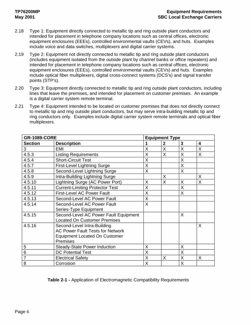
2.17 Table 2-1 provides a guide for applying the aforementioned electromagnetic compatibility requirements. Application of the various criteria is a function of the type of equipment under consideration, its connection to the telecommunications network and the intended location of the equipment. For the purpose of determining the applicable criteria of GR-1089-CORE, network equipment has been grouped into four categories. It is necessary to determine which of the four categories best applies to the equipment under test. Table 2-1 may be consulted once the equipment has been appropriately categorized as follows:
TP76200MP Equipment Requirements May 2001 SBC Local Exchange Carriers
Page 6
2.18 Type 1: Equipment directly connected to metallic tip and ring outside plant conductors and
intended for placement in telephone company locations such as central offices, electronic equipment enclosures (EEEs), controlled environmental vaults (CEVs), and huts. Examples include voice and data switches, multiplexers and digital carrier systems.
2.19 Type 2: Equipment not directly connected to metallic tip and ring outside plant conductors (includes equipment isolated from the outside plant by channel banks or office repeaters) and intended for placement in telephone company locations such as central offices, electronic equipment enclosures (EEEs), controlled environmental vaults (CEVs) and huts. Examples include optical fiber multiplexers, digital cross-connect systems (DCS’s) and signal transfer points (STP’s).
2.20 Type 3: Equipment directly connected to metallic tip and ring outside plant conductors, including lines that leave the premises, and intended for placement on customer premises. An example is a digital carrier system remote terminal.
2.21 Type 4: Equipment intended to be located on customer premises that does not directly connect to metallic tip and ring outside plant conductors, but may serve intra-building metallic tip and ring conductors only. Examples include digital carrier system remote terminals and optical fiber multiplexers.
GR-1089-CORE Equipment Type Section Description 1 2 3 4 3 EMI X X X X 4.5.3 Listing Requirements X X X X 4.5.4 Short-Circuit Test X X 4.5.7 First-Level Lightning Surge X X 4.5.8 Second-Level Lightning Surge X X 4.5.9 Intra-Building Lightning Surge X X 4.5.10 Lightning Surge (AC Power Port) X X X X 4.5.11 Current-Limiting Protector Test X X 4.5.12 First-Level AC Power Fault X X 4.5.13 Second-Level AC Power Fault X 4.5.14 Second-Level AC Power Fault
Series-Type Equipment X
4.5.15 Second-Level AC Power Fault Equipment Located On Customer Premises
X
4.5.16 Second-Level Intra-Building AC Power Fault Tests for Network Equipment Located On Customer Premises
X
5 Steady-State Power Induction X X 6 DC Potential Test X X 7 Electrical Safety X X X X 8 Corrosion X X
Table 2-1 - Application of Electromagnetic Compatibility Requirements
Equipment Requirements TP76200MP SBC Local Exchange Carriers May 2001
Page 7
3 ACOUSTIC NOISE
3.01 The equipment shall meet the acoustic noise requirements stated in section 4.6 of GR-63-CORE.
3.02 The equipment shall be tested in accordance with section 5.6 of GR-63-CORE.
4 ELECTROSTATIC DISCHARGE (ESD)
4.01 Equipment shall meet the ESD immunity criteria requirements for normal operation and installation and repair that are found in section 2.2 of Telcordia's GR-1089-CORE document. All tests shall be conducted as described in section 2.4 of GR-1089 and IEC Publication 61000-4-2.
4.02 Any additional equipment-specific requirements in paragraph 2.2.3.1 of GR-1089-CORE shall be described.
4.03 Maintenance documentation shall comply with paragraph 2.2.3.2 in GR-1089-CORE.
5 GROUNDING
5.01 Grounding and bonding requirements for structures, equipment and power systems are provided in BSP 802-001-180MP. Structures, equipment and power systems submitted for evaluation shall meet applicable requirements listed in (a) through (i) below, which list key sections of the BSP. Documentation of compliance is required and shall be returned with form ESR-001, ESR-002 or ESR-ANC as appropriate. The documentation may be in the form of test reports, equipment drawings or specifications, installation instructions, engineering guides, detailed descriptions of the grounding and bonding arrangements, etc. Details shall include a description of all connectors used for ground reference paths within the equipment and those between the equipment and the point of connection(s) to the central office ground system. The size(s) of all grounding conductor(s) (wire, bus bar, etc.) shall also be provided, listed by either AWG or cross-sectional area in circular mils or mm2. (a) 1.5 - Conductors (b) 1.6 - Connectors (c) 3.3.02 thru 3.3.08 - DC Systems, DC-DC Converters (d) 3.3.12 thru 3.3.19 - Rectifiers, Inverters, etc. (e) 3.5 B. - Transport Systems and Equipment (f) 3.5 C. - Miscellaneous Frames, Racks, Cabinets & Equipment (g) 3.5 F. - Bay Ground Lead (h) 4.7 - Isolated Bonding Network Equipment (i) Electronic Equipment Enclosures
5.02 It is a requirement that the fault current path for the output of any imbedded power source be able to conduct any current likely to be imposed on it without sustaining damage to any components of the path. Sources may be rectifiers, dc-dc converters, dc-ac inverters or other sources equipped with overcurrent protective devices or current limit mechanisms. To demonstrate compliance with this requirement, the supplier may choose either method (a) or (b) below, or if appropriate, a combination of the two.
TP76200MP Equipment Requirements May 2001 SBC Local Exchange Carriers
Page 8
a) The supplier shall furnish a report describing the tests and the results for the short
circuit tests described in Section 9.8 of Telcordia’s GR-1089-CORE document. These tests are to be performed on all imbedded ac and dc power sources, regardless of output.
(b) The supplier shall furnish sufficient information to perform a paper analysis of the fault current paths of all imbedded ac and dc power sources.
Note: The above does not apply to a battery or a string of batteries that is not equipped with an overcurrent protective device or devices. If the output of a rectifier or similar source is normally connected in parallel with batteries, the batteries shall be disconnected during fault current tests on the rectifier or other source.
For either (a) or (b) above, the fault current path must include that for all imbedded sources and all components of the ultimate equipment configuration that will be used. For example, if an imbedded source provides power to more than one shelf or frame, all shelves and/or frames must be used (or simulated) during the short circuit tests, or described in detail for a paper analysis.
If an imbedded source uses an output overcurrent protective device (fuse, circuit breaker) the device must operate during the short circuit tests without allowing damage to any part of the fault current path. For a paper analysis, the rating or setting of the overcurrent device must be provided.
If an imbedded source uses output current limiting, no component of the output fault current path may be damaged during continuous operation while in current limit mode during the short circuit tests. For a paper analysis, the output fault current inception value and the continuous output fault current value (after fold-down or fold-back) must be provided.
If the output of more than one imbedded source (e.g. dc-dc converter) is in parallel, all sources must be operating during the short circuit tests. For a paper analysis, the combined output fault current values must be stated.
If short circuit tests are not performed, the description of the fault current path must provide information of sufficient detail to evaluate the path’s ability to carry the available fault current. In this case, the term “detail” means data such as cross-sectional area (in circular mils) of conductors, bus bars, etc., quantity and size of screws, backplane trace equivalent cross-sectional area, type of connectors, etc.
5.03 State whether the equipment is designed for, or restricted to, installation in a common bonding network environment, in an isolated bonding network environment, or in either environment. (A common bonding network may also be referred to as an integrated ground plane or multi-point ground. An isolated bonding network may also be referred to as an isolated ground plane or single point ground).
5.04 Within the equipment, there shall be no direct electrical continuity between the return side of an external power source and the equipment framework or chassis.
Equipment Requirements TP76200MP SBC Local Exchange Carriers May 2001
Page 9
6 THERMAL
A. TEMPERATURE AND HUMIDITY
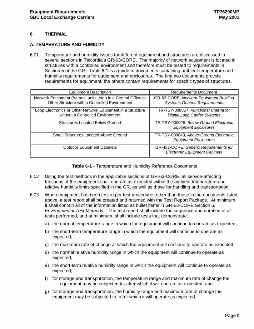
6.01 Temperature and humidity issues for different equipment and structures are discussed in several sections in Telcordia’s GR-63-CORE. The majority of network equipment is located in structures with a controlled environment and therefore must be tested to requirements in Section 5 of the GR. Table 6-1 is a guide to documents containing ambient temperature and humidity requirements for equipment and enclosures. The first two documents provide requirements for equipment, the others contain requirements for specific types of structures.
Equipment Description Requirements Document Network Equipment (frames, units, etc.) in a Central Office or
Other Structure with a Controlled Environment GR-63-CORE, Network-Equipment Building
Systems Generic Requirements
Loop Electronics or Other Network Equipment in a Structure without a Controlled Environment
TR-TSY-000057, Functional Criteria for Digital Loop Carrier Systems
Structures Located Below Ground TR-TSY-000026, Below-Ground Electronic Equipment Enclosures
Small Structures Located Above Ground TR-TSY-000043, Above-Ground Electronic Equipment Enclosures
Outdoor Equipment Cabinets GR-487-CORE, Generic Requirements for Electronic Equipment Cabinets
Table 6-1 - Temperature and Humidity Reference Documents
6.02 Using the test methods in the applicable sections of GR-63-CORE, all service-affecting functions of the equipment shall operate as expected within the ambient temperature and relative humidity limits specified in the GR, as well as those for handling and transportation.
6.03 When equipment has been tested per test procedures other than those in the documents listed above, a test report shall be created and returned with the Test Report Package. At minimum, it shall contain all of the information listed as bullet items in GR-63-CORE Section 5, Environmental Test Methods. The test report shall include the sequence and duration of all tests performed, and at minimum, shall include tests that demonstrate: a) the normal temperature range in which the equipment will continue to operate as expected, b) the short-term temperature range in which the equipment will continue to operate as
expected, c) the maximum rate of change at which the equipment will continue to operate as expected, d) the normal relative humidity range in which the equipment will continue to operate as
expected, e) the short-term relative humidity range in which the equipment will continue to operate as
expected, f) for storage and transportation, the temperature range and maximum rate of change the
equipment may be subjected to, after which it will operate as expected, and g) for storage and transportation, the humidity range and maximum rate of change the
equipment may be subjected to, after which it will operate as expected.
TP76200MP Equipment Requirements May 2001 SBC Local Exchange Carriers
Page 10
B. ALTITUDE 6.04 The equipment shall meet the altitude requirements and objective stated in section 4.1.3 of
Telcordia publication GR-63-CORE.
C. HEAT DISSIPATION 6.05 The normal continuous duty heat dissipated (in Watts) by the equipment shall be stated on
TP76200 form ESP-001 or ESP-002 form. Normal continuous duty is considered the operating mode the equipment will function at for 22 hours over 24 hour period. Heat dissipation is usually considered the power draw by equipment minus work accomplished by equipment and the value can be calculated or measured by the manufacturer. Manufacturer shall provide heat dissipation data for each shelf of equipment as well as the system when more than one shelf is supplied . When more than one configuration of a product is available, heat release information of each board option, shelf arrangement or system package shall be provided to SBC. The manufacturer shall provide the overall dimensions of the equipment (without aisle space dimensions) for SBC to determine the equipment footprint. Manufacturer shall state Yes if heat dissipation data has been provided.
6.06 Manufacturer shall state Yes if product is electric motor fan forced cooled or No if product is convection cooled or cooled by other than fan forced cooling design. Other cooling methods shall be explained with a statement included as attachment to form ESP-001/002.
6.07 Equipment cooling scheme in central offices typically has cooling air inlet in front face of equipment and heat exhaust to back or top of equipment. Manufacturer shall state Yes if cooling air flow of your product adheres to this cooling scheme. Heat exhaust to side(s) or front of equipment either as primary or secondary paths requires answering this question with a No.
6.08 Face temperature of equipment shall never exceed 38 degrees C (100 degrees F) at an ambient room temperature of 26 degrees C (79 degrees F). Manufacturer shall state Yes if in conformance to face temperature limit.
7 DC POWER
General
The following requirements are referenced from, but not limited to, the American National Standards Institute (ANSI) publication ANSI T1.315-1994, and other standards or documents as indicated.
7.01 All equipment shall operate on a normal -48 Vdc power source.
7.02 The equipment shall operate properly for its intended service life with voltage variations between -42.0 Vdc and -56.7 Vdc measured at the first distribution point of the equipment.
7.03 Embedded DC-DC converters shall meet the standard in 7.02 but shall also be tested for proper operation for 1 minute at –40.0 Vdc.
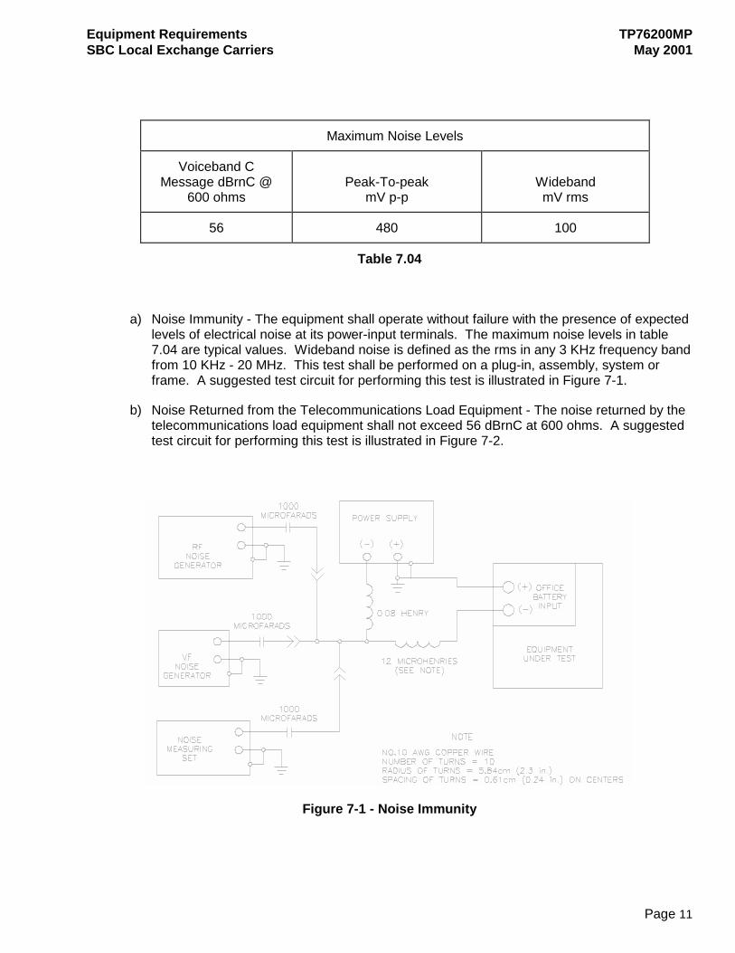
7.04 The equipment shall meet the expected levels of electrical noise at the equipment’s power input terminals. The maximum noise levels are outlined in Table 7.04 as determined ANSI T1.315-1994.
Equipment Requirements TP76200MP SBC Local Exchange Carriers May 2001
Page 11
Maximum Noise Levels
Voiceband C Message dBrnC @
600 ohms
Peak-To-peak
mV p-p
Wideband mV rms
56 480 100
Table 7.04
a) Noise Immunity - The equipment shall operate without failure with the presence of expected levels of electrical noise at its power-input terminals. The maximum noise levels in table 7.04 are typical values. Wideband noise is defined as the rms in any 3 KHz frequency band from 10 KHz - 20 MHz. This test shall be performed on a plug-in, assembly, system or frame. A suggested test circuit for performing this test is illustrated in Figure 7-1.
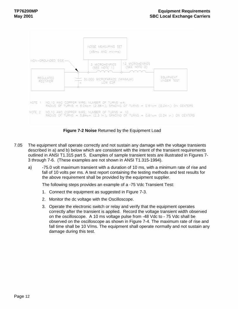
b) Noise Returned from the Telecommunications Load Equipment - The noise returned by the telecommunications load equipment shall not exceed 56 dBrnC at 600 ohms. A suggested test circuit for performing this test is illustrated in Figure 7-2.
Figure 7-1 - Noise Immunity
TP76200MP Equipment Requirements May 2001 SBC Local Exchange Carriers
Page 12
Figure 7-2 Noise Returned by the Equipment Load
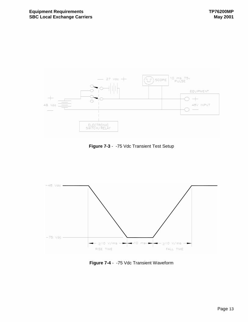
7.05 The equipment shall operate correctly and not sustain any damage with the voltage transients
described in a) and b) below which are consistent with the intent of the transient requirements outlined in ANSI T1.315 part 5. Examples of sample transient tests are illustrated in Figures 7-3 through 7-6. (These examples are not shown in ANSI T1.315-1994). a) -75.0 volt maximum transient with a duration of 10 ms, with a minimum rate of rise and
fall of 10 volts per ms. A test report containing the testing methods and test results for the above requirement shall be provided by the equipment supplier. The following steps provides an example of a -75 Vdc Transient Test: 1. Connect the equipment as suggested in Figure 7-3. 2. Monitor the dc voltage with the Oscilloscope. 3. Operate the electronic switch or relay and verify that the equipment operates
correctly after the transient is applied. Record the voltage transient width observed on the oscilloscope. A 10 ms voltage pulse from -48 Vdc to - 75 Vdc shall be observed on the oscilloscope as shown in Figure 7-4. The maximum rate of rise and fall time shall be 10 V/ms. The equipment shall operate normally and not sustain any damage during this test.
Equipment Requirements TP76200MP SBC Local Exchange Carriers May 2001
Page 13
Figure 7-3 - -75 Vdc Transient Test Setup
Figure 7-4 - -75 Vdc Transient Waveform
TP76200MP Equipment Requirements May 2001 SBC Local Exchange Carriers
Page 14
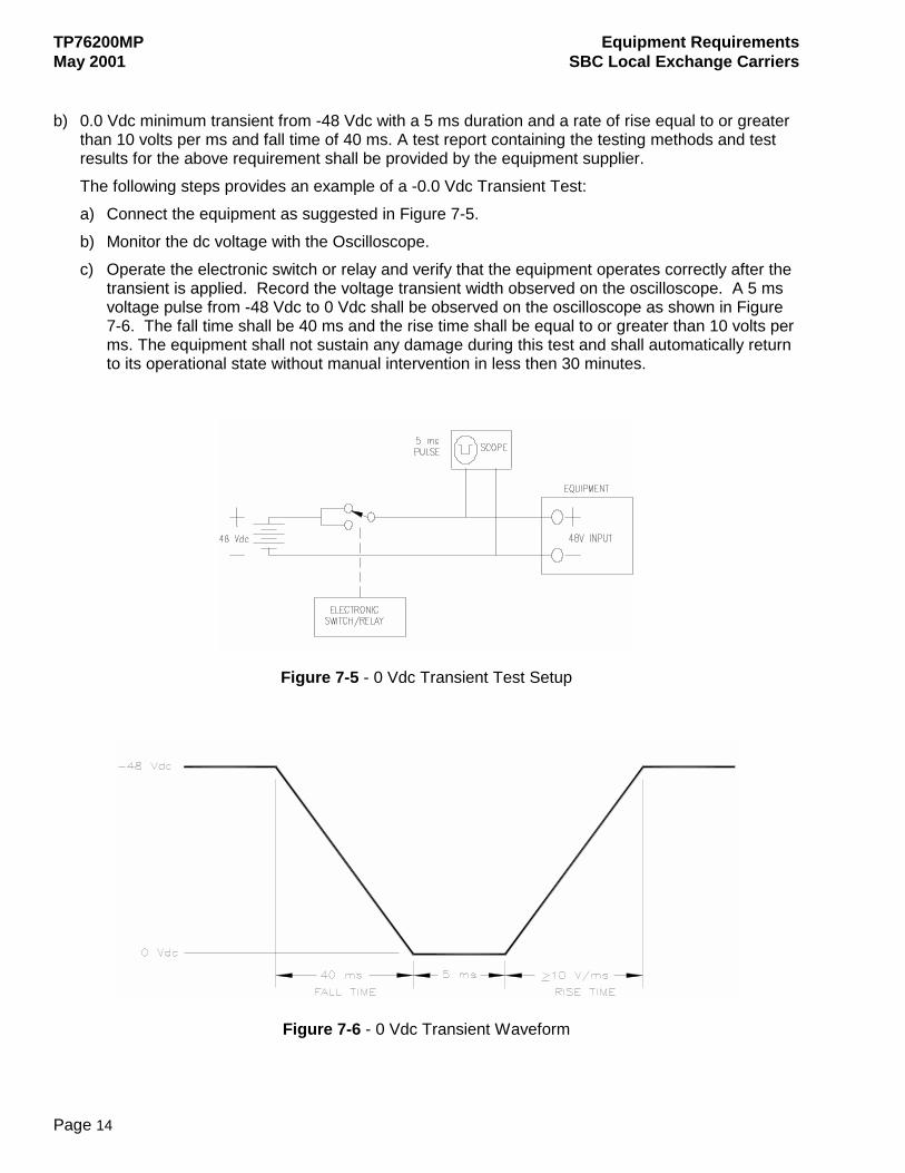
b) 0.0 Vdc minimum transient from -48 Vdc with a 5 ms duration and a rate of rise equal to or greater
than 10 volts per ms and fall time of 40 ms. A test report containing the testing methods and test results for the above requirement shall be provided by the equipment supplier. The following steps provides an example of a -0.0 Vdc Transient Test: a) Connect the equipment as suggested in Figure 7-5. b) Monitor the dc voltage with the Oscilloscope. c) Operate the electronic switch or relay and verify that the equipment operates correctly after the
transient is applied. Record the voltage transient width observed on the oscilloscope. A 5 ms voltage pulse from -48 Vdc to 0 Vdc shall be observed on the oscilloscope as shown in Figure 7-6. The fall time shall be 40 ms and the rise time shall be equal to or greater than 10 volts per ms. The equipment shall not sustain any damage during this test and shall automatically return to its operational state without manual intervention in less then 30 minutes.
Figure 7-5 - 0 Vdc Transient Test Setup
Figure 7-6 - 0 Vdc Transient Waveform
Equipment Requirements TP76200MP SBC Local Exchange Carriers May 2001
Page 15
7.06 List 1 power drains information shall be provided on appropriate ESP form for individual units and maximum configured systems. Also provide information on how the drain data was derived (e.g., empirical testing or calculations). List 1 drains are defined as follows: a) List 1 - Drains that are used to size batteries and rectifiers. These drains represent the
average busy-hour current drawn at normal (-52 Vdc or -48 Vdc) operating voltages.
7.07 The minimum voltage the equipment will tolerate with no damage shall be stated. A test report containing the test methods and test results for the equipment supplier shall provide the above requirement.
7.08 Connectors used to attach the product to external power cabling shall conform to the following requirements: (a) For applications where the size of wire supplying or distributing power to/from the equipment is 16 AWG stranded power cable or larger, connectors shall be crimp-type. Power input terminations that will accept # 8 AWG connector terminations shall meet the same specifications, but shall also be a dual threaded post termination able to accept the appropriate two hole crimp connection. This termination may be either 5/8” or ½ “on centers. Equipment surface terminations shall accept crimp connections that meet the following specifications:
• UL467 Grounding and Bonding Equipment • UL486A Pressure Wire Connections…And Terminal Type Connectors • UL 486C Splicing Wire Connectors • CSAC22.2 • Mil Spec 25036 and Mil T Spec 7928 • Equipment submitted for approval should provide a UL listed (power) termination
strip designed and designated as “field wireable” to insure product compliance with the UL listing of the product. This termination strip should be able to accommodate a ring lug connectors that comply with the UL, CSA and Mil Spec listings.
(b) For applications where the size of wire supplying power to the equipment is 18 AWG power cable or smaller, mechanical connectors may be used. Mechanical connectors shall meet the following specifications:
• The connector shall be listed by a Nationally Recognized Test Laboratory for its intended use.
• The connector shall be tested to assure long-term tightness and reliability. The following tests are acceptable for this requirement; IEC 60068-2-6, "Basic Environmental Test Procedures, Part 2: Test Fc and Guidance: Vibration (sinusoidal); EIA Specifications 364-27B (4/17/96) and 364-28D (6/24/99) shock and vibration testing. Other vibration test procedures demonstrating long-term reliability will be considered for evaluation.
• The product supplier shall provide documentation of routine maintenance (if any) associated with the supplied connector.
7.09 De-powering information shall be provided for the equipment under consideration. The information shall include any special or sequenced type de-powering procedures that are associated with the equipment. Service manuals containing this information are acceptable.
TP76200MP Equipment Requirements May 2001 SBC Local Exchange Carriers
Page 16
7.10 Redundant power feeders are required for all equipment serving network elements. The term
network element refers to all switching, transport and operator services equipment, and any adjuncts for those elements. Redundant power feeder information must be provided in the supplier's response documentation to be in compliance with this item.
7.11 Each redundant power feeder shall have its own battery return conductor. This design concept shall also carry through directly to each piece of equipment. Battery return information must be provided in the supplier's response documentation to be in compliance with this item.
7.12 The equipment shall provide visual power alarm and status indications by indicator devices mounted directly on the equipment. The equipment shall also be capable of transmitting alarm signals to an office alarm circuit and to sending circuits for remote surveillance using dry loop relay contacts or other means. Power alarm and status reporting information must be provided in the supplier's response documentation to be in compliance with this item.
7.13 Equipment incorporating the use of power distribution apparatus which uses capacitors shall be fused to protect the power distribution bus from a shorted capacitor. Fuse and protection information must be provided in the supplier's response documentation to be in compliance with this item.
7.14 Power plant equipment used for outside plant applications (e.g., Cabinets, Controlled Environmental Vaults, Universal Enclosures, Huts, Customer Premises) shall be equipped with the following minimum alarm requirements: a) Power alarms: Rectifier Failure 1, Rectifier Failure 2, AC Failure, Battery Failure, Fuse
Alarm, Low Voltage 1, Low Voltage 2, and High Voltage 1. b) Alarm devices (e.g., relay) shall be capable of providing both open and close loop alarm
logic for all power alarms indicated above.
• Suppliers shall use the appropriate ESR form to indicate whether the equipment under consideration is equipped with the above alarm characteristics.
7.15 Equipment power requirement information is used to identify the type(s) and amount of power that must be planned and provided for the equipment. Equipment power requirements shall be documented categorically by the overall system requirements, individual frames, and equipment units that power must be provided to. Equipment power requirements shall include: a) The source of power to be provided (commercial, UPS, etc.). b) The types and voltage levels of power that is required (-48 Vdc, 120 Vac, etc.). c) The number of required loads and load designations when appropriate. d) The incremental power load/drain for each power supply required. e) A schematic by frame and/or equipment unit of all power conductors to be installed beyond
its power distribution source. f) A detailed discussion of reasoning for all available equipment power options.
7.16 Suppliers shall use appropriate ESR form to indicate whether the above equipment power requirements information has been documented and is being provided at this time.
Equipment Requirements TP76200MP SBC Local Exchange Carriers May 2001
Page 17
8 AIRBORNE CONTAMINANTS
8.01 Equipment intended for installation in controlled environment spaces (indoors shall meet the Airborne Contaminants requirements for indoor equipment as stated in section 4.5 of Telcordia’s GR-63-CORE. Conformance to this requirement for reactive gases and hygroscopic fine particulate can be demonstrated through the test method given in Section 5.5 of the GR.
8.02 Equipment intended for in outdoor air (i.e., cabinets installed on pads or poles) with no filtration shall meet the Airborne Contaminants requirements for outdoor equipment as stated in section 4.5 of Telcordia’s GR-63-CORE. Conformance to this requirement for reactive gases and hygroscopic fine particulate can be demonstrated through the test method given in Section 5.5 of the GR.
8.03 Fan cooled equipment shall be equipped with filters. Exception: Fans used to cool the outside of sealed equipment cabinets need not be fitted with particulate filters.
8.04 Equipment fan filters shall have a minimum dust arrestance of 80 % - this represents a low 10-15 % American Society of Heating, Refrigerating, and Air-Conditioning Engineers (ASHRAE) dust spot rating.
8.05 Fan filters shall have a minimum fire rating of UL Class 2. 8.06 Construction and system fit of equipment fan filters shall prevent any air bypass. 8.07 The equipment manufacturer shall provide a method for determining equipment fan filter
replacement schedules. 8.08 The equipment shall be provisioned for fan filter replacement with the fan shut down or blocked
to prevent handling contamination. Some designs where the filters are withdrawn from the airflow for removal (e.g., door-mounted filters) satisfy the intent of this requirement.
9 SHOCK AND VIBRATION
A. Handling and Transportation
9.01 Network equipment shall be designed with tolerance for shock of transportation and handling from manufacturer’s facilities to job sites without sustaining physical damage or affecting functional performance. The manufacturer shall state Yes if in compliance to handling and transportation shock requirements specified in Telcordia document GR-63-CORE, No if not in compliance or if product has not been tested. Product test documentation may not be requested with the understanding that the equipment manufacturer is responsible to assure receipt of acceptable and functional products to the job sites.
9.02 Network equipment shall be designed with tolerance for transportation and handling from manufacturer’s facilities to the job site without sustaining physical damage or affecting functional performance. The manufacturer shall state Yes if in compliance to handling and transportation vibration requirements specified in Telcordia document GR-63, No if not in compliance or if product has not been tested. SBC may not request test documentation with the understanding that the equipment manufacturer is responsible to assure receipt of an acceptable and functional product to the SBC job site.
TP76200MP Equipment Requirements May 2001 SBC Local Exchange Carriers
Page 18
B. Earthquake 9.03 Equipment buildings may be located in high earthquake risk areas. Network equipment
considered for SBC Level 2 service (Level 3 Telcordia SR-3580) shall be designed for service in high seismic risk locations. Equipment shall demonstrate conformance to Telcordia GR-63-COREor ANSI T1-329 earthquake requirements by having equipment assembly tested on shake table and submitting documentation of successful test results. The manufacturer shall state Yes if in compliance to earthquake requirements specified in Telcordia document GR-63-CORE or ANSI T1-329, No if not in compliance or if product has not been tested. Manufacturer may state N/A for products that are intended for low seismic risk applications only and has written statement from SBC confirming the limited application. Equipment considered for Level 1 service does not require earthquake tests to be conducted, however, equipment shall be installed in framework suitable for resisting earthquake loads and framework secured appropriately to building.
9.04 Earthquake shake table tests shall be performed at a laboratory capable of performing tests per GR-63. Manufacturer shall state Yes if name/location of testing laboratory has been forwarded and received by SBC seismic protection engineer.
9.05 All network equipment shall have circuit pack latches or retainers to prevent pack and module walkout. Ejectors are not retainers and should not be used for that purpose. Manufacturer shall state Yes if latch or retainer is provided for all circuit packs and modules.
9.06 Hard drive storage units used with network equipment shall be designed with tolerance for shock and vibration by physical isolation of drives, backup systems or self-recovery capabilities to assure service integrity. Manufacturer shall state Yes if product has capability.
9.07 Network equipment shall be designed for mounting in telecommunications industry standard framework, relay racks. However, equipment deeper than 12 inches, heavier than 400 pounds or designed for special housings may require framework other than standard relay racks. For safety consideration, a loaded framework during transport or on site awaiting installation should temporarily be able to stand upright on it’s own when not secured. If weight distribution of equipment in framework results in framework falling backward or forward, special deeper framework is to be provided. Overnight or longer storage of loaded framework shall always be secured in SBC equipment areas. Manufacturer shall state Yes if product can be installed in standard telecommunications two upright framework, relay racks or No if special framework is necessary for equipment.
9.08 All network equipment assemblies 7’-0” tall and under shall be designed for freestanding installation in SBC equipment areas. Freestanding is defined as framework not secured overhead but have provisions for floor anchors of appropriate size and quantity to secure equipment from overturning under worst-case site conditions. Manufacturer shall state Yes if product has been designed for freestanding configuration.
C. Office Vibrations 9.09 Network equipment shall be designed for operation under office vibration conditions specified in
Telcordia document GR-63-CORE. The manufacturer shall state Yes if in compliance to office vibration requirements in Telcordia document GR-63-CORE, No if not in compliance or if product has not been tested. SBC may not request test documentation with the understanding that the equipment manufacturer is responsible to assure operational reliability for conditions that may exist in SBC equipment locations.
Equipment Requirements TP76200MP SBC Local Exchange Carriers May 2001
Page 19
D. Floor Loading 9.10 Floor loading requirements specified in Telcordia document GR-63-CORE shall not be
exceeded. The manufacturer shall consider the worst case configuration of heaviest arrangement within a single framework when analyzing floor load. The configuration may need to include weight within a frame contributed from equipment supplied by others. Manufacturer shall state Yes if product is in conformance to floor load limits.
10 FIRE RESISTANCE
10.01 This part provides the minimum fire resistance requirements for equipment products and apparatus intended for installation in the network equipment facilities. All equipment shall be tested or otherwise evaluated for compliance with the fire resistance criteria provided in this part.
10.02 Generally, products that have been determined to be acceptable for purchase from a fire resistance perspective do not have to be retested or evaluated unless subsequent changes to the product include one or more of the following characteristics:
• A substantial increase in the product's polymeric content (fuel load),
• A decrease in the fire resistance characteristic/rating of included components,
• An increase in the density of installed electrical components, or
• A physical change in the product’s framework or enclosure construction.
A. Materials/Components 10.03 The materials and components used in the construction and interconnection of equipment shall
comply with the most current issue of ANSI/T1-307. Generally, materials and components shall be constructed of polymeric materials having an oxygen index of 28% or greater and a fire resistance characteristic equivalent to or better than Under Writers Laboratories (UL) standard UL 94 V-1. Cable and wire shall generally be listed for their purpose.
Protective Barriers
10.04 Exposed nonmetallic equipment frame components such as protective covers, viewing panels, etc.: a) Shall have a fire resistance characteristic equivalent to or better than UL-94 V-0 if the
component’s exposed surface area is ≤1 ft.2 (0.09 m2), or b) Shall have a fire resistance characteristic equivalent to or better than UL-94 5VA if the
component’s exposed surface area is greater than >1 ft.2 (0.09 m2) and it’s thickness is less than 0.18 inches (5 mm), and
c) Shall have a maximum flame spread rating of 150 if the component's exposed surface area is >10 ft.2 (0.9 m2). Flame spread ratings shall be determined by product test methods that are equivalent to UL standard 723 Test for Surface Burning Characteristics of Building Materials.
TP76200MP Equipment Requirements May 2001 SBC Local Exchange Carriers
Page 20
B. Fire Spread This part applies to equipment products intended for installation in indoor network equipment facilities, and may apply to equipment products intended for installation in outdoor enclosures and environments. General 10.05 Equipment products shall comply with the appropriate fire spread performance criteria provided
in the latest issue of GR-63-CORE with the following exceptions: Fire Propagation - Frame Level Products
(a) Peak heat release rates shall not exceed 150 kW at any time during product testing.
(b) Average heat release rates shall not exceed 100kW over any 30-minute period of time during product testing.
Fire Propagation - Shelf Level Products
(c) Peak heat release rates shall not exceed 50 kW at any time during product testing.
(d) Average heat release rates shall not exceed 35 kW over any 30-minute period of time during product testing.
• Equipment suppliers shall use appropriate ESR form to indicate whether the product(s) under consideration have been tested to the criteria of 10.05 and whether a copy of the test report and test video issued by the testing facility is included for review and retention. An expected test date shall be given for all products that have not yet been tested to the above criteria.
11 SPATIAL A. General 11.01 This part provides the physical requirements for equipment units, and equipment systems
intended for use in indoor network equipment areas. This part does not apply to power equipment or office distributing frames, and is not applicable to equipment intended solely for use in outdoor equipment enclosures, or controlled environment vaults.
11.02 The word system as used in this part refers to multi-unit and multi-frame equipment configurations that collectively perform one or more telecommunications or data management functions. System equipment is normally furnished preinstalled in one or more equipment framework assemblies.
11.03 The term equipment unit as used in this part refers to stand alone products that are generally field mounted on an as needed basis.
Equipment Requirements TP76200MP SBC Local Exchange Carriers May 2001
Page 21
B. Network Switching Systems 11.04 Network switching systems refers to a contiguous group of equipment frames whose primary
purpose is typically the management of local area calling traffic. Network switching systems shall be designed so that all equipment frames, intrasystem cabling, and intrasystem cable racking can be accommodated in an equipment area having a 9'-0" clear ceiling height. To accomplish this: (a) Equipment frames should not exceed 7'-0" in vertical height.
(b) All intrasystem cable and cable racking arrangements within and between equipment lineups shall be contained within the area between the top of the equipment frames and the 9'-0" level.
(c) The vertical space between the 9'-0" and 10'-0" levels shall be allocated to network interconnecting cable and its associated cable management apparatus. Intrasystem cable rack designs should include provisions for the support and management of office cabling that terminates in the switch as well as cabling that transverses the switch's equipment area.
• Suppliers shall use appropriate ESR form to indicate whether their switching equipment design complies with 11.04 through 11.04(c).
C. Other Equipment Systems 11.05 Frame level equipment systems intended for random location within a building:
a) Shall be mounted in frames or cabinets that are 7'-0" or less in vertical height and equal to or greater than the overall depth of installed equipment and all possible network interconnection cabling.
b) Shall include any required bolt-on framework apparatus required to comply with the equipment and cabling protection requirement of a), and
c) Should not exceed 2'-6" in overall width. d) Should not exceed 15” in depth. e) Should not require more than 2’ 6” of aisle space at the rear and 3’ 0” of aisle space at the
front for equipment installation and maintenance purposes. 11.06 Multi-frame equipment systems should employ the use of a common equipment framework
depth to facilitate movement of people and apparatus along equipment aisles. When it is necessary that frameworks of different depths be used, angled frame base transitional hardware shall be included with, or be optionally available for the shallower frames to avoid abrupt changes in equipment framework depths.
D. Equipment Units
11.07 Equipment units shall: (a) Be designed so they are installed from the front and cabled from the rear of equipment
framework assemblies, (b) Incorporate the use of holes or closed slots for attachment to equipment framework
mounting surfaces,
TP76200MP Equipment Requirements May 2001 SBC Local Exchange Carriers
Page 22
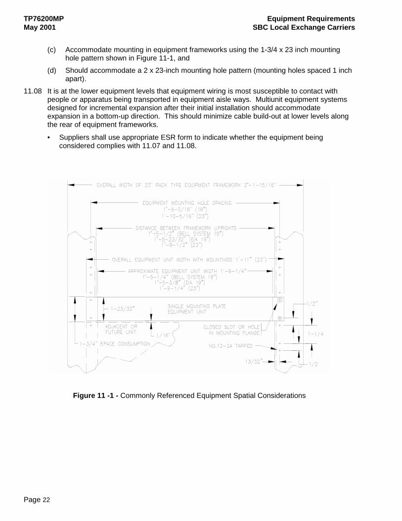
(c) Accommodate mounting in equipment frameworks using the 1-3/4 x 23 inch mounting
hole pattern shown in Figure 11-1, and (d) Should accommodate a 2 x 23-inch mounting hole pattern (mounting holes spaced 1 inch
apart). 11.08 It is at the lower equipment levels that equipment wiring is most susceptible to contact with
people or apparatus being transported in equipment aisle ways. Multiunit equipment systems designed for incremental expansion after their initial installation should accommodate expansion in a bottom-up direction. This should minimize cable build-out at lower levels along the rear of equipment frameworks.
• Suppliers shall use appropriate ESR form to indicate whether the equipment being considered complies with 11.07 and 11.08.
Figure 11 -1 - Commonly Referenced Equipment Spatial Considerations
Equipment Requirements TP76200MP SBC Local Exchange Carriers May 2001
Page 23
12 PLANNING AND ENGINEERING DOCUMENTATION 12.01 This part defines the categories of equipment engineering information required from
manufacturers for network equipment products. This part will be used to determine if the information associated with the equipment has been sufficiently documented to support equipment space planning functions and the detailed integration of the product(s) into a network equipment environment.
12.02 The information described in this part should be a dedicated part or section of the user reference material (user's manual) describing the product’s overall functionality, network application and integration requirements/recommendations.
• Suppliers shall use form ESR-002 to indicate whether the planning and engineering information described in the subsequent text of 15(A) and (B) has been documented, and is provided for review.
A. Space Planning General
12.03 Space planning information enables a person to accurately determine where network equipment shall or should be located relative to other network elements, and the equipment's overall office floor space requirements. It includes an equipment overview describing the equipment's primary network function, its associated equipment if any, and all supportive reasoning affecting its location within a building or within an equipment frame (for shelf level products).
System Equipment
12.04 Space planning information for equipment systems shall indicate via office floor plan illustrations (overhead views) and supportive text the optimum physical arrangement(s) of all equipment frames comprising the equipment system. The space planning information shall also include any alternative equipment arrangements that may be considered when optimum arrangements are not possible due to floor space restrictions.
12.05 Space planning illustrations for expandable equipment systems shall indicate the incremental increase in floor space requirements associated with the equipment's service expansion, and any restrictions there may be relative to the equipment's overall expansion.
12.06 The following information should be included in equipment system space planning information: • Floor plan designation(s) of all equipment
frames comprising the equipment system • Number of frames required per equipment system
functionality
• Overall dimensions of equipment frames • ac and dc power requirements
• Minimum front and rear aisle spacing requirements
• Volume of required network interconnect cabling per frame
• Equipment location restrictions • Additional floor space requirements, if any
• Equipment weight • Maximum heat dissipation per frame in watts per ft2
• Detailed description of equipment framework
Table 12 -1 - Equipment System Information
TP76200MP Equipment Requirements May 2001 SBC Local Exchange Carriers
Page 24
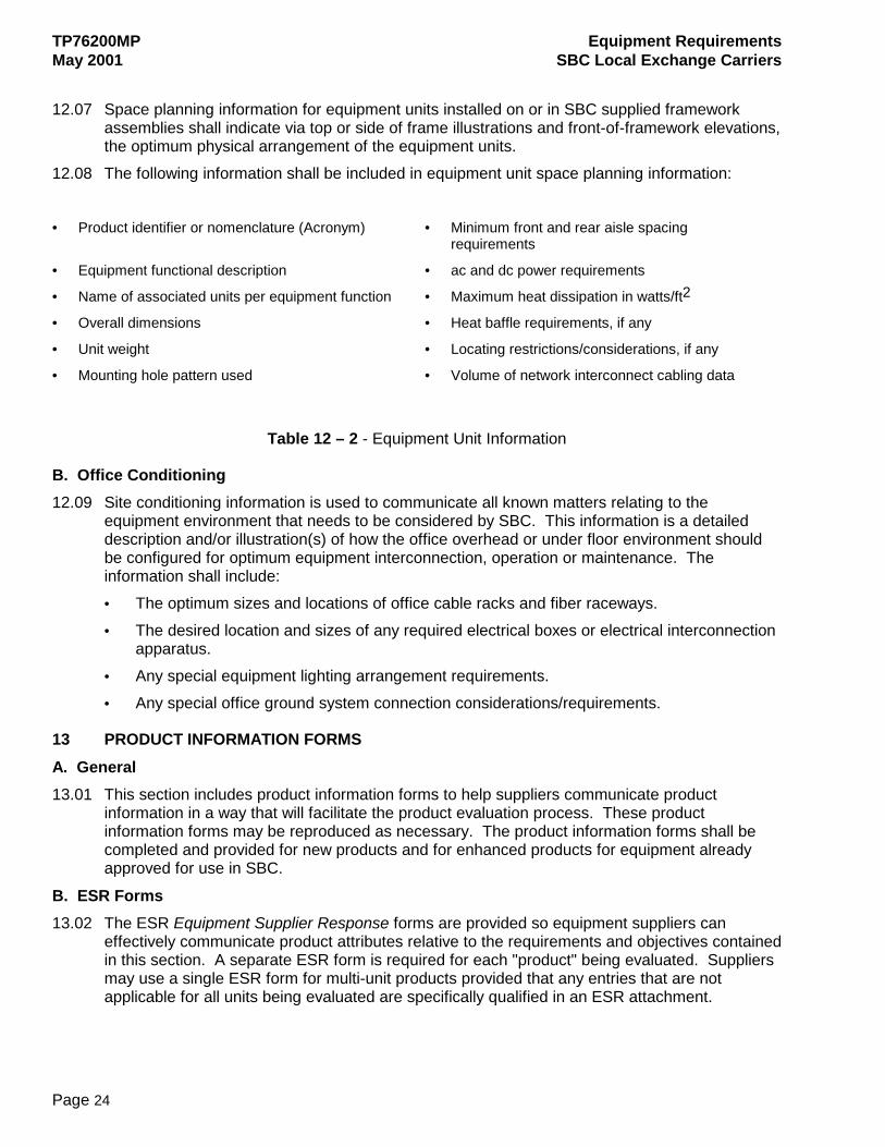
12.07 Space planning information for equipment units installed on or in SBC supplied framework
assemblies shall indicate via top or side of frame illustrations and front-of-framework elevations, the optimum physical arrangement of the equipment units.
12.08 The following information shall be included in equipment unit space planning information: • Product identifier or nomenclature (Acronym) • Minimum front and rear aisle spacing
requirements
• Equipment functional description • ac and dc power requirements
• Name of associated units per equipment function • Maximum heat dissipation in watts/ft2
• Overall dimensions • Heat baffle requirements, if any
• Unit weight • Locating restrictions/considerations, if any
• Mounting hole pattern used • Volume of network interconnect cabling data
Table 12 – 2 - Equipment Unit Information
B. Office Conditioning 12.09 Site conditioning information is used to communicate all known matters relating to the
equipment environment that needs to be considered by SBC. This information is a detailed description and/or illustration(s) of how the office overhead or under floor environment should be configured for optimum equipment interconnection, operation or maintenance. The information shall include: • The optimum sizes and locations of office cable racks and fiber raceways. • The desired location and sizes of any required electrical boxes or electrical interconnection
apparatus. • Any special equipment lighting arrangement requirements. • Any special office ground system connection considerations/requirements.
13 PRODUCT INFORMATION FORMS A. General 13.01 This section includes product information forms to help suppliers communicate product
information in a way that will facilitate the product evaluation process. These product information forms may be reproduced as necessary. The product information forms shall be completed and provided for new products and for enhanced products for equipment already approved for use in SBC.
B. ESR Forms 13.02 The ESR Equipment Supplier Response forms are provided so equipment suppliers can
effectively communicate product attributes relative to the requirements and objectives contained in this section. A separate ESR form is required for each "product" being evaluated. Suppliers may use a single ESR form for multi-unit products provided that any entries that are not applicable for all units being evaluated are specifically qualified in an ESR attachment.
Equipment Requirements TP76200MP SBC Local Exchange Carriers May 2001
Page 25
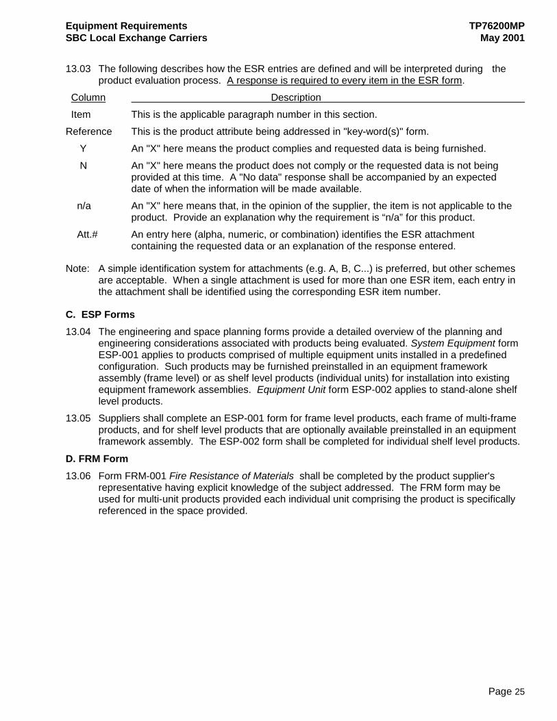
13.03 The following describes how the ESR entries are defined and will be interpreted during the
product evaluation process. A response is required to every item in the ESR form. Column Description Item This is the applicable paragraph number in this section.
Reference This is the product attribute being addressed in "key-word(s)" form. Y An "X" here means the product complies and requested data is being furnished. N An "X" here means the product does not comply or the requested data is not being provided at this time. A "No data" response shall be accompanied by an expected date of when the information will be made available. n/a An "X" here means that, in the opinion of the supplier, the item is not applicable to the product. Provide an explanation why the requirement is “n/a” for this product. Att.# An entry here (alpha, numeric, or combination) identifies the ESR attachment containing the requested data or an explanation of the response entered.
Note: A simple identification system for attachments (e.g. A, B, C...) is preferred, but other schemes are acceptable. When a single attachment is used for more than one ESR item, each entry in the attachment shall be identified using the corresponding ESR item number.
C. ESP Forms 13.04 The engineering and space planning forms provide a detailed overview of the planning and
engineering considerations associated with products being evaluated. System Equipment form ESP-001 applies to products comprised of multiple equipment units installed in a predefined configuration. Such products may be furnished preinstalled in an equipment framework assembly (frame level) or as shelf level products (individual units) for installation into existing equipment framework assemblies. Equipment Unit form ESP-002 applies to stand-alone shelf level products.
13.05 Suppliers shall complete an ESP-001 form for frame level products, each frame of multi-frame products, and for shelf level products that are optionally available preinstalled in an equipment framework assembly. The ESP-002 form shall be completed for individual shelf level products.
D. FRM Form 13.06 Form FRM-001 Fire Resistance of Materials shall be completed by the product supplier's
representative having explicit knowledge of the subject addressed. The FRM form may be used for multi-unit products provided each individual unit comprising the product is specifically referenced in the space provided.
TP76200MP Equipment Requirements May 2001 SBC Local Exchange Carriers
Page 26
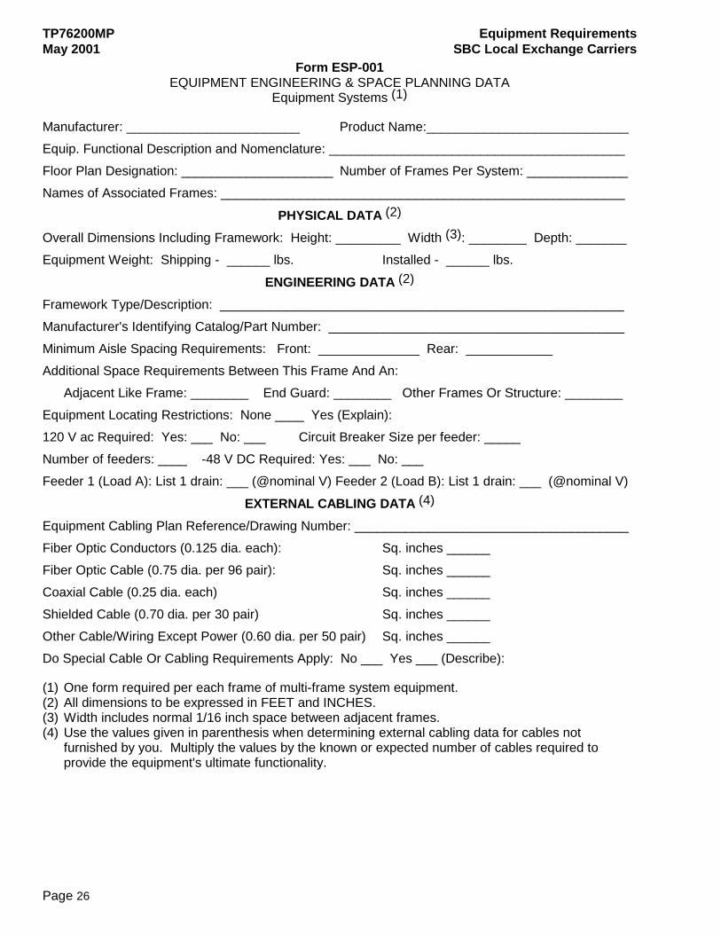
Form ESP-001 EQUIPMENT ENGINEERING & SPACE PLANNING DATA
Equipment Systems (1)
Manufacturer: ________________________ Product Name:____________________________ Equip. Functional Description and Nomenclature: _________________________________________ Floor Plan Designation: _____________________ Number of Frames Per System: ______________ Names of Associated Frames: ________________________________________________________
PHYSICAL DATA (2) Overall Dimensions Including Framework: Height: _________ Width (3): ________ Depth: _______ Equipment Weight: Shipping - ______ lbs. Installed - ______ lbs.
ENGINEERING DATA (2) Framework Type/Description: ________________________________________________________ Manufacturer's Identifying Catalog/Part Number: _________________________________________ Minimum Aisle Spacing Requirements: Front: ______________ Rear: ____________ Additional Space Requirements Between This Frame And An:
Adjacent Like Frame: ________ End Guard: ________ Other Frames Or Structure: ________ Equipment Locating Restrictions: None ____ Yes (Explain): 120 V ac Required: Yes: ___ No: ___ Circuit Breaker Size per feeder: _____ Number of feeders: ____ -48 V DC Required: Yes: ___ No: ___ Feeder 1 (Load A): List 1 drain: ___ (@nominal V) Feeder 2 (Load B): List 1 drain: ___ (@nominal V)
EXTERNAL CABLING DATA (4) Equipment Cabling Plan Reference/Drawing Number: ______________________________________ Fiber Optic Conductors (0.125 dia. each): Sq. inches ______ Fiber Optic Cable (0.75 dia. per 96 pair): Sq. inches ______ Coaxial Cable (0.25 dia. each) Sq. inches ______ Shielded Cable (0.70 dia. per 30 pair) Sq. inches ______ Other Cable/Wiring Except Power (0.60 dia. per 50 pair) Sq. inches ______ Do Special Cable Or Cabling Requirements Apply: No ___ Yes ___ (Describe):
(1) One form required per each frame of multi-frame system equipment. (2) All dimensions to be expressed in FEET and INCHES. (3) Width includes normal 1/16 inch space between adjacent frames. (4) Use the values given in parenthesis when determining external cabling data for cables not
furnished by you. Multiply the values by the known or expected number of cables required to provide the equipment's ultimate functionality.
Equipment Requirements TP76200MP SBC Local Exchange Carriers May 2001
Page 27
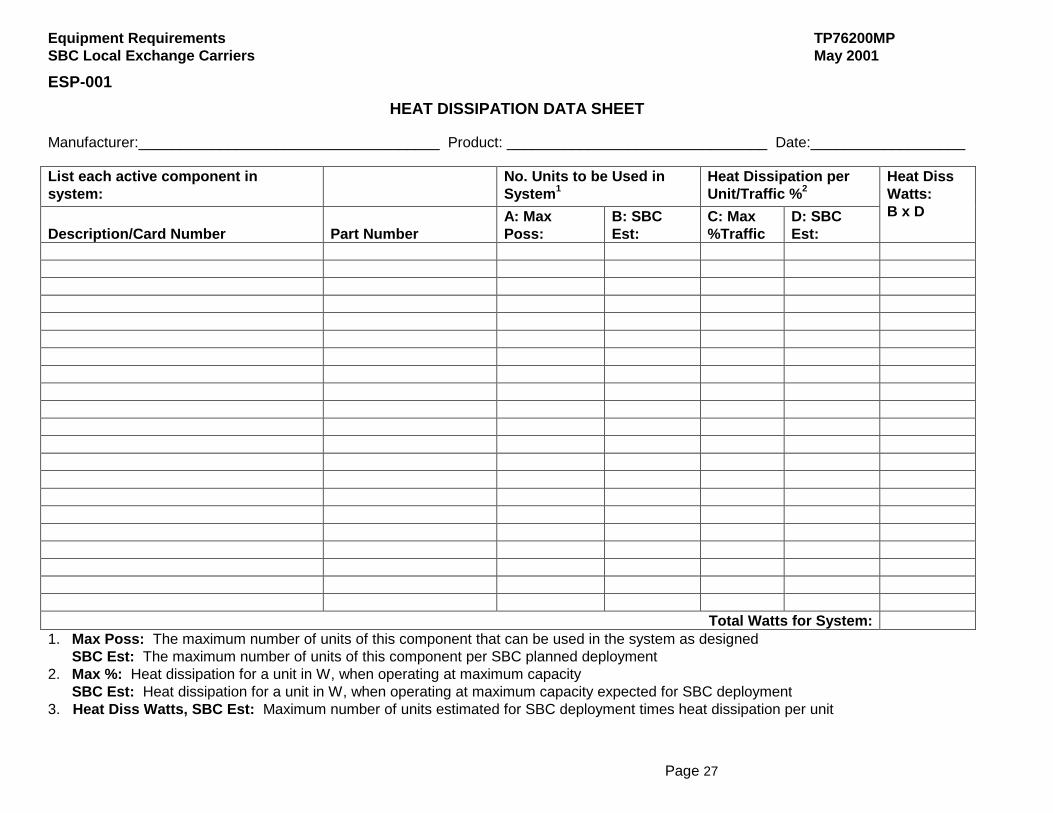
ESP-001 HEAT DISSIPATION DATA SHEET
Manufacturer:_____________________________________ Product: ________________________________ Date:___________________
List each active component in system:
No. Units to be Used in System1
Heat Dissipation per Unit/Traffic %2
Description/Card Number
Part Number
A: Max Poss:
B: SBC Est:
C: Max %Traffic
D: SBC Est:
Heat Diss Watts: B x D
Total Watts for System: 1. Max Poss: The maximum number of units of this component that can be used in the system as designed
SBC Est: The maximum number of units of this component per SBC planned deployment 2. Max %: Heat dissipation for a unit in W, when operating at maximum capacity
SBC Est: Heat dissipation for a unit in W, when operating at maximum capacity expected for SBC deployment 3. Heat Diss Watts, SBC Est: Maximum number of units estimated for SBC deployment times heat dissipation per unit
TP76200MP Equipment Requirements May 2001 SBC Local Exchange Carriers
Page 28
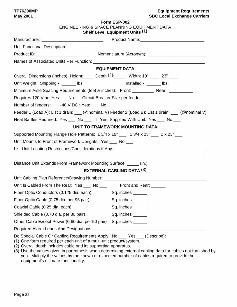
Form ESP-002 ENGINEERING & SPACE PLANNING EQUIPMENT DATA
Shelf Level Equipment Units (1) Manufacturer: __________________________ Product Name:___________________________ Unit Functional Description: __________________________________________________________ Product ID: ______________________ Nomenclature (Acronym): _________________________ Names of Associated Units Per Function: _______________________________________________
EQUIPMENT DATA Overall Dimensions (inches): Height:____ Depth (2):_____ Width: 19” ____ 23” ____ Unit Weight: Shipping - ______ lbs. Installed - ______ lbs. Minimum Aisle Spacing Requirements (feet & inches): Front: _________ Rear: __________ Requires 120 V ac: Yes ___ No ___Circuit Breaker Size per feeder: ____ Number of feeders: ___ -48 V DC : Yes: ___ No: ___ Feeder 1 (Load A): List 1 drain: ___ (@nominal V) Feeder 2 (Load B): List 1 drain: ___ (@nominal V) Heat Baffles Required: Yes ___ No ___ If Yes, Supplied With Unit: Yes ___ No ___
UNIT TO FRAMEWORK MOUNTING DATA Supported Mounting Flange Hole Patterns: 1 3/4 x 19" ___ 1 3/4 x 23" ___ 2 x 23" ___ Unit Mounts to Front of Framework Uprights: Yes ___ No ___ List Unit Locating Restrictions/Considerations if Any: ______________________________________ ________________________________________________________________________________ Distance Unit Extends From Framework Mounting Surface: _____ (in.)
EXTERNAL CABLING DATA (3) Unit Cabling Plan Reference/Drawing Number: ___________________________________________ Unit Is Cabled From The Rear: Yes ___ No ___ Front and Rear: ______ Fiber Optic Conductors (0.125 dia. each): Sq. inches ______ Fiber Optic Cable (0.75 dia. per 96 pair): Sq. inches ______ Coaxial Cable (0.25 dia. each) Sq. inches ______ Shielded Cable (0.70 dia. per 30 pair) Sq. inches ______ Other Cable Except Power (0.60 dia. per 50 pair) Sq. inches ______ Required Alarm Leads And Designations: _______________________________________________ Do Special Cable Or Cabling Requirements Apply: No ___ Yes ___ (Describe): (1) One form required per each unit of a multi-unit product/system. (2) Overall depth includes cable and its supporting apparatus. (3) Use the values given in parenthesis when determining external cabling data for cables not furnished by
you. Multiply the values by the known or expected number of cables required to provide the equipment's ultimate functionality.

Equipment Requirements TP76200MP SBC Local Exchange Carriers May 2001
Page 29
ESP-002 HEAT DISSIPATION DATA SHEET
Manufacturer:_____________________________________ Product: ________________________________ Date:___________________
List each active component in system:
No. Units to be Used in System1
Heat Dissipation per Unit/Traffic %2
Description/Card Number
Part Number
A: Max Poss:
B: SBC Est:
C: Max %Traffic
D: SBC Est:
Heat Diss Watts: B x D
Total Watts for System: 1. Max Poss: The maximum number of units of this component that can be used in the system as designed
SBC Est: The maximum number of units of this component per SBC planned deployment 2. Max %: Heat dissipation for a unit in W, when operating at maximum capacity
SBC Est: Heat dissipation for a unit in W, when operating at maximum capacity expected for SBC deployment 3. Heat Diss Watts, SBC Est: Maximum number of units estimated for SBC deployment times heat dissipation per unit
TP76200MP Equipment Requirements May 2001 SBC Local Exchange Carriers
Page 30
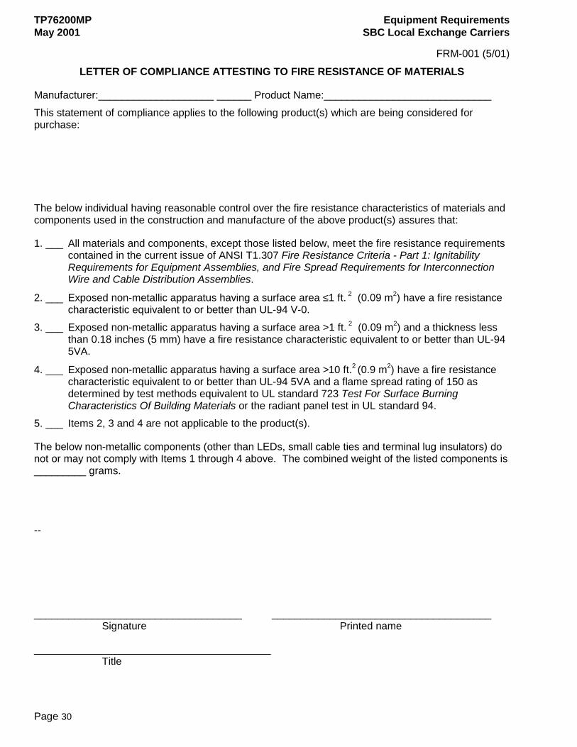
FRM-001 (5/01)
LETTER OF COMPLIANCE ATTESTING TO FIRE RESISTANCE OF MATERIALS
Manufacturer:____________________ ______ Product Name:_____________________________ This statement of compliance applies to the following product(s) which are being considered for purchase:
The below individual having reasonable control over the fire resistance characteristics of materials and components used in the construction and manufacture of the above product(s) assures that:
1. ___ All materials and components, except those listed below, meet the fire resistance requirements contained in the current issue of ANSI T1.307 Fire Resistance Criteria - Part 1: Ignitability Requirements for Equipment Assemblies, and Fire Spread Requirements for Interconnection Wire and Cable Distribution Assemblies.
2. ___ Exposed non-metallic apparatus having a surface area ≤1 ft. 2 (0.09 m2) have a fire resistance characteristic equivalent to or better than UL-94 V-0.
3. ___ Exposed non-metallic apparatus having a surface area >1 ft. 2 (0.09 m2) and a thickness less than 0.18 inches (5 mm) have a fire resistance characteristic equivalent to or better than UL-94 5VA.
4. ___ Exposed non-metallic apparatus having a surface area >10 ft.2 (0.9 m2) have a fire resistance characteristic equivalent to or better than UL-94 5VA and a flame spread rating of 150 as determined by test methods equivalent to UL standard 723 Test For Surface Burning Characteristics Of Building Materials or the radiant panel test in UL standard 94.
5. ___ Items 2, 3 and 4 are not applicable to the product(s).
The below non-metallic components (other than LEDs, small cable ties and terminal lug insulators) do not or may not comply with Items 1 through 4 above. The combined weight of the listed components is _________ grams.
-- ____________________________________ ______________________________________ Signature Printed name
_________________________________________ Title
Equipment Requirements TP76200MP SBC Local Exchange Carriers May 2001
Page 31
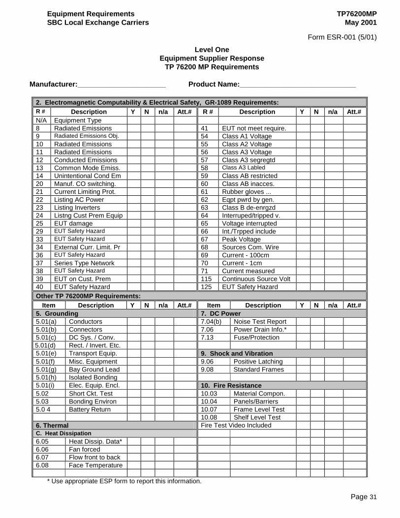
Form ESR-001 (5/01)
Level One Equipment Supplier Response
TP 76200 MP Requirements
Manufacturer:______________________ Product Name:_____________________________
2. Electromagnetic Computability & Electrical Safety, GR-1089 Requirements: R # Description Y N n/a Att.# R # Description Y N n/a Att.# N/A Equipment Type 8 Radiated Emissions 41 EUT not meet require. 9 Radiated Emissions Obj. 54 Class A1 Voltage 10 Radiated Emissions 55 Class A2 Voltage 11 Radiated Emissions 56 Class A3 Voltage 12 Conducted Emissions 57 Class A3 segregtd 13 Common Mode Emiss. 58 Class A3 Labled 14 Unintentional Cond Em 59 Class AB restricted 20 Manuf. CO switching. 60 Class AB inacces. 21 Current Limiting Prot. 61 Rubber gloves ... 22 Listing AC Power 62 Eqpt pwrd by gen. 23 Listing Inverters 63 Class B de-enrgzd 24 Listng Cust Prem Equip 64 Interruped/tripped v. 25 EUT damage 65 Voltage interrupted 29 EUT Safety Hazard 66 Int./Trpped include 33 EUT Safety Hazard 67 Peak Voltage 34 External Curr. Limit. Pr 68 Sources Com. Wire 36 EUT Safety Hazard 69 Current - 100cm 37 Series Type Network 70 Current - 1cm 38 EUT Safety Hazard 71 Current measured 39 EUT on Cust. Prem 115 Continuous Source Volt 40 EUT Safety Hazard 125 EUT Safety Hazard Other TP 76200MP Requirements:
Item Description Y N n/a Att.# Item Description Y N n/a Att.# 5. Grounding 7. DC Power 5.01(a) Conductors 7.04(b) Noise Test Report 5.01(b) Connectors 7.06 Power Drain Info.* 5.01(c) DC Sys. / Conv. 7.13 Fuse/Protection 5.01(d) Rect. / Invert. Etc. 5.01(e) Transport Equip. 9. Shock and Vibration 5.01(f) Misc. Equipment 9.06 Positive Latching 5.01(g) Bay Ground Lead 9.08 Standard Frames 5.01(h) Isolated Bonding 5.01(i) Elec. Equip. Encl. 10. Fire Resistance 5.02 Short Ckt. Test 10.03 Material Compon. 5.03 Bonding Environ 10.04 Panels/Barriers 5.0 4 Battery Return 10.07 Frame Level Test 10.08 Shelf Level Test 6. Thermal Fire Test Video Included C. Heat Dissipation 6.05 Heat Dissip. Data* 6.06 Fan forced 6.07 Flow front to back 6.08 Face Temperature
* Use appropriate ESP form to report this information.
TP76200MP Equipment Requirements May 2001 SBC Local Exchange Carriers
Page 32
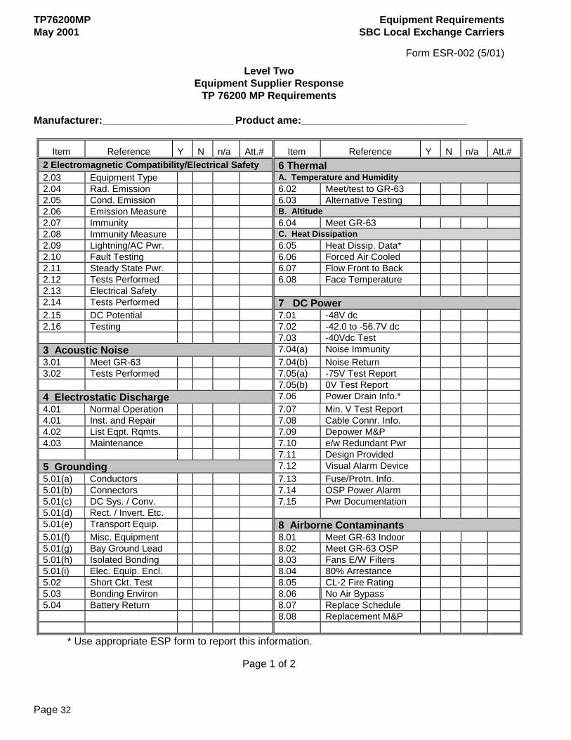
Form ESR-002 (5/01)
Level Two Equipment Supplier Response
TP 76200 MP Requirements
Manufacturer:_______________________ Product ame:_____________________________
Item Reference Y N n/a Att.# Item Reference Y N n/a Att.# 2 Electromagnetic Compatibility/Electrical Safety 6 Thermal 2.03 Equipment Type A. Temperature and Humidity 2.04 Rad. Emission 6.02 Meet/test to GR-63 2.05 Cond. Emission 6.03 Alternative Testing 2.06 Emission Measure B. Altitude 2.07 Immunity 6.04 Meet GR-63 2.08 Immunity Measure C. Heat Dissipation 2.09 Lightning/AC Pwr. 6.05 Heat Dissip. Data* 2.10 Fault Testing 6.06 Forced Air Cooled 2.11 Steady State Pwr. 6.07 Flow Front to Back 2.12 Tests Performed 6.08 Face Temperature 2.13 Electrical Safety 2.14 Tests Performed 7 DC Power 2.15 DC Potential 7.01 -48V dc 2.16 Testing 7.02 -42.0 to -56.7V dc 7.03 -40Vdc Test 3 Acoustic Noise 7.04(a) Noise Immunity 3.01 Meet GR-63 7.04(b) Noise Return 3.02 Tests Performed 7.05(a) -75V Test Report 7.05(b) 0V Test Report 4 Electrostatic Discharge 7.06 Power Drain Info.* 4.01 Normal Operation 7.07 Min. V Test Report 4.01 Inst. and Repair 7.08 Cable Connr. Info. 4.02 List Eqpt. Rqmts. 7.09 Depower M&P 4.03 Maintenance 7.10 e/w Redundant Pwr 7.11 Design Provided 5 Grounding 7.12 Visual Alarm Device 5.01(a) Conductors 7.13 Fuse/Protn. Info. 5.01(b) Connectors 7.14 OSP Power Alarm 5.01(c) DC Sys. / Conv. 7.15 Pwr Documentation 5.01(d) Rect. / Invert. Etc. 5.01(e) Transport Equip. 8 Airborne Contaminants 5.01(f) Misc. Equipment 8.01 Meet GR-63 Indoor 5.01(g) Bay Ground Lead 8.02 Meet GR-63 OSP 5.01(h) Isolated Bonding 8.03 Fans E/W Filters 5.01(i) Elec. Equip. Encl. 8.04 80% Arrestance 5.02 Short Ckt. Test 8.05 CL-2 Fire Rating 5.03 Bonding Environ 8.06 No Air Bypass 5.04 Battery Return 8.07 Replace Schedule 8.08 Replacement M&P
* Use appropriate ESP form to report this information.
Page 1 of 2
Equipment Requirements TP76200MP SBC Local Exchange Carriers May 2001
Page 33
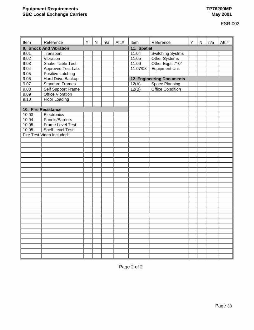
ESR-002
Item Reference Y N n/a Att.# Item Reference Y N n/a Att.# 9. Shock And Vibration 11. Spatial 9.01 Transport 11.04 Switching Systms 9.02 Vibration 11.05 Other Systems 9.03 Shake Table Test 11.06 Other Eqpt. 7'-0" 9.04 Approved Test Lab. 11.07/08 Equipment Unit 9.05 Positive Latching 9.06 Hard Drive Backup 12. Engineering Documents 9.07 Standard Frames 12(A) Space Planning 9.08 Self Support Frame 12(B) Office Condition 9.09 Office Vibration 9.10 Floor Loading 10. Fire Resistance 10.03 Electronics 10.04 Panels/Barriers 10.05 Frame Level Test 10.05 Shelf Level Test Fire Test Video Included:
Page 2 of 2
TP76200MP Equipment Requirements May 2001 SBC Local Exchange Carriers
Page 34
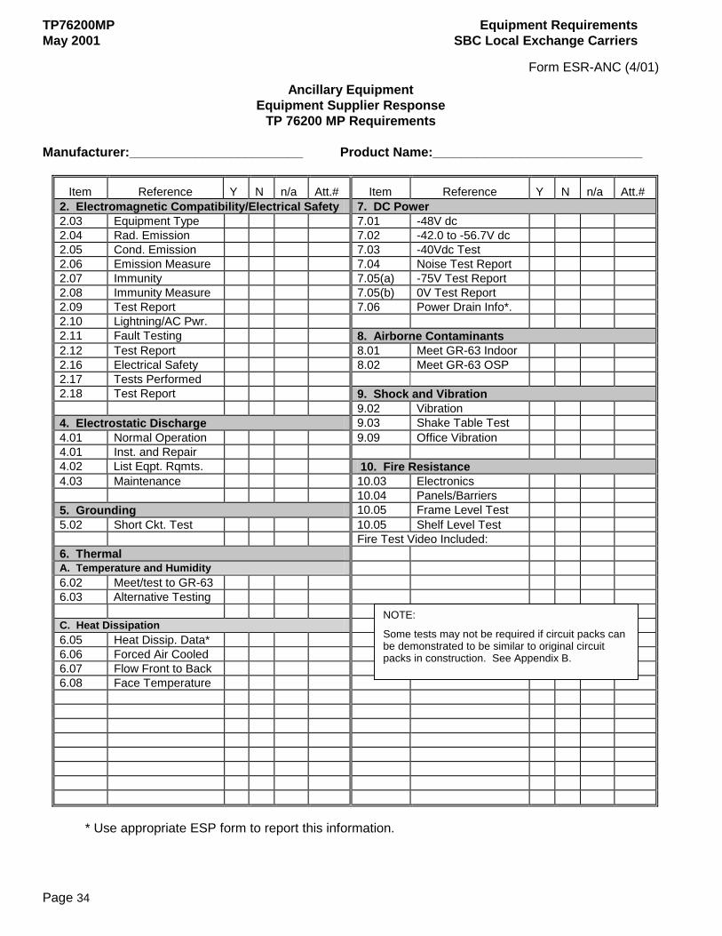
Form ESR-ANC (4/01)
Ancillary Equipment Equipment Supplier Response
TP 76200 MP Requirements
Manufacturer:________________________ Product Name:_____________________________
Item Reference Y N n/a Att.# Item Reference Y N n/a Att.# 2. Electromagnetic Compatibility/Electrical Safety 7. DC Power 2.03 Equipment Type 7.01 -48V dc 2.04 Rad. Emission 7.02 -42.0 to -56.7V dc 2.05 Cond. Emission 7.03 -40Vdc Test 2.06 Emission Measure 7.04 Noise Test Report 2.07 Immunity 7.05(a) -75V Test Report 2.08 Immunity Measure 7.05(b) 0V Test Report 2.09 Test Report 7.06 Power Drain Info*. 2.10 Lightning/AC Pwr. 2.11 Fault Testing 8. Airborne Contaminants
2.12 Test Report 8.01 Meet GR-63 Indoor 2.16 Electrical Safety 8.02 Meet GR-63 OSP 2.17 Tests Performed 2.18 Test Report 9. Shock and Vibration 9.02 Vibration 4. Electrostatic Discharge 9.03 Shake Table Test 4.01 Normal Operation 9.09 Office Vibration 4.01 Inst. and Repair 4.02 List Eqpt. Rqmts. 10. Fire Resistance 4.03 Maintenance 10.03 Electronics 10.04 Panels/Barriers 5. Grounding 10.05 Frame Level Test 5.02 Short Ckt. Test 10.05 Shelf Level Test Fire Test Video Included: 6. Thermal A. Temperature and Humidity 6.02 Meet/test to GR-63 6.03 Alternative Testing C. Heat Dissipation 6.05 Heat Dissip. Data* 6.06 Forced Air Cooled 6.07 Flow Front to Back 6.08 Face Temperature
* Use appropriate ESP form to report this information.
NOTE:
Some tests may not be required if circuit packs can be demonstrated to be similar to original circuit packs in construction. See Appendix B.
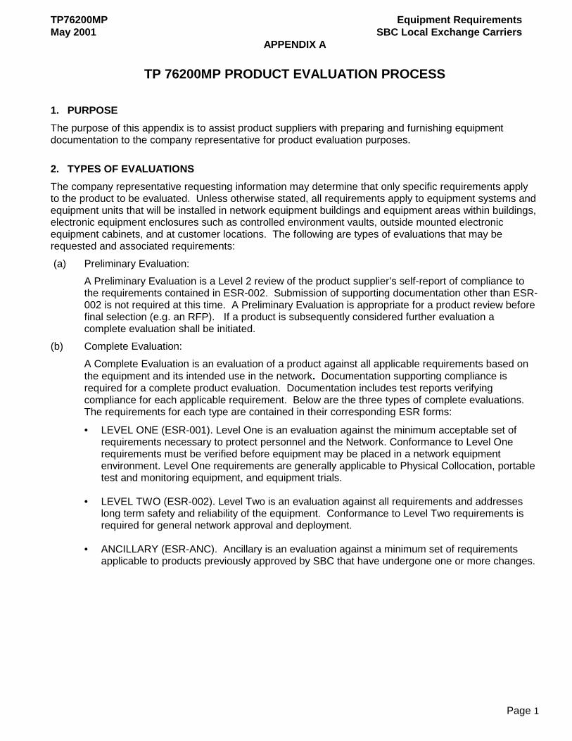
TP76200MP Equipment Requirements May 2001 SBC Local Exchange Carriers
APPENDIX A
Page 1
TP 76200MP PRODUCT EVALUATION PROCESS
1. PURPOSE The purpose of this appendix is to assist product suppliers with preparing and furnishing equipment documentation to the company representative for product evaluation purposes.
2. TYPES OF EVALUATIONS The company representative requesting information may determine that only specific requirements apply to the product to be evaluated. Unless otherwise stated, all requirements apply to equipment systems and equipment units that will be installed in network equipment buildings and equipment areas within buildings, electronic equipment enclosures such as controlled environment vaults, outside mounted electronic equipment cabinets, and at customer locations. The following are types of evaluations that may be requested and associated requirements: (a) Preliminary Evaluation:
A Preliminary Evaluation is a Level 2 review of the product supplier’s self-report of compliance to the requirements contained in ESR-002. Submission of supporting documentation other than ESR-002 is not required at this time. A Preliminary Evaluation is appropriate for a product review before final selection (e.g. an RFP). If a product is subsequently considered further evaluation a complete evaluation shall be initiated.
(b) Complete Evaluation: A Complete Evaluation is an evaluation of a product against all applicable requirements based on the equipment and its intended use in the network. Documentation supporting compliance is required for a complete product evaluation. Documentation includes test reports verifying compliance for each applicable requirement. Below are the three types of complete evaluations. The requirements for each type are contained in their corresponding ESR forms:
• LEVEL ONE (ESR-001). Level One is an evaluation against the minimum acceptable set of requirements necessary to protect personnel and the Network. Conformance to Level One requirements must be verified before equipment may be placed in a network equipment environment. Level One requirements are generally applicable to Physical Collocation, portable test and monitoring equipment, and equipment trials.
• LEVEL TWO (ESR-002). Level Two is an evaluation against all requirements and addresses long term safety and reliability of the equipment. Conformance to Level Two requirements is required for general network approval and deployment.
• ANCILLARY (ESR-ANC). Ancillary is an evaluation against a minimum set of requirements applicable to products previously approved by SBC that have undergone one or more changes.
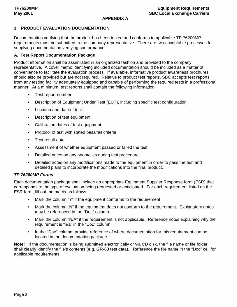
TP76200MP Equipment Requirements May 2001 SBC Local Exchange Carriers
APPENDIX A
Page 2
3. PRODUCT EVALUATION DOCUMENTATION
Documentation verifying that the product has been tested and conforms to applicable TP 76200MP requirements must be submitted to the company representative. There are two acceptable processes for supplying documentation verifying conformance:
A. Test Report Documentation Package Product information shall be assimilated in an organized fashion and provided to the company representative. A cover memo identifying included documentation should be included as a matter of convenience to facilitate the evaluation process. If available, informative product awareness brochures should also be provided but are not required. Relative to product test reports, SBC accepts test reports from any testing facility adequately equipped and capable of performing the required tests in a professional manner. At a minimum, test reports shall contain the following information:
• Test report number
• Description of Equipment Under Test (EUT), including specific test configuration
• Location and date of test
• Description of test equipment
• Calibration dates of test equipment
• Protocol of test with stated pass/fail criteria
• Test result data
• Assessment of whether equipment passed or failed the test
• Detailed notes on any anomalies during test procedure
• Detailed notes on any modifications made to the equipment in order to pass the test and detailed plans to incorporate the modifications into the final product.
TP 76200MP Forms Each documentation package shall include an appropriate Equipment Supplier Response form (ESR) that corresponds to the type of evaluation being requested or anticipated. For each requirement listed on the ESR form, fill out the matrix as follows:
• Mark the column “Y” if the equipment conforms to the requirement
• Mark the column “N” if the equipment does not conform to the requirement. Explanatory notes may be referenced in the “Doc” column.
• Mark the column “N/A” if the requirement is not applicable. Reference notes explaining why the requirement is “n/a” in the “Doc” column.
• In the “Doc” column, provide reference of where documentation for this requirement can be located in the documentation package.
Note: If the documentation is being submitted electronically or via CD disk, the file name or file folder shall clearly identify the file’s contents (e.g. GR-63 test data). Reference the file name in the “Doc” cell for applicable requirements.
TP76200MP Equipment Requirements May 2001 SBC Local Exchange Carriers
APPENDIX A
Page 3
For each type and level of evaluation the following forms shall be submitted:
• Preliminary: A completed ESR-002 and the relevant ESP-001 or ESP-002 form shall be submitted for review. An informative product brochure describing the physical and electrical characteristics of the equipment may be used in lieu of ESP forms. An indication of planned testing should be indicated for any product tests not yet performed.
• Level One: Completed forms ESR-001, ESP-001 or ESP-002, FRM-001, and applicable test report documentation shall be submitted for review.
• Level Two: Completed forms ESR-002, ESP-001 or ESP-002, FRM-001, HWM-001 and all test report documentation shall be submitted for review. An indication of planned testing shall be indicated for any product tests not yet performed.
• Ancillary: Completed forms ESR-ANC, FRM-001, applicable test report documentation, and/or a description of product revisions shall be submitted for review.
NOTE: Product will not be approved for use without receipt of correct completed forms.
SBC Documentation Package Evaluation Process The SBC Common Systems Product Evaluation group will review the product Documentation Package. If the product cannot be evaluated as compliant to all applicable requirements, an Initial Letter will be sent to the company representative specifying the areas that are not evaluated in conformance and what further action is required of the product supplier. Upon receipt of the Initial Letter, the product supplier may forward supplemental data to or contact the company representative, the SBC Product Evaluation Group Coordinator or a specific SME regarding non-compliance resolution. Contact information for the Group Coordinator and SMEs is contained in the Initial Letter. Documentation, either electronic or hard copy, forwarded to SBC containing supplemental data in response to an Initial Letter should identify the contents of documentation and reference the Product Log number assigned to the product, the SME who requested the data and the non-compliance requirement the data is addressing. The SME(s) who requested the documentation will evaluate supplemental data forwarded to SBC by the product supplier. If the supplemental data is sufficient to allow all open areas to be evaluated as in conformance to applicable requirements, a Final Letter will be sent to the company representative notifying them that the product conforms to requirements. If there are still open items after supplemental data has been reviewed, a Product Evaluation Status letter will be sent to the company representative giving the status of the product and what further action the product supplier needs to take. SBC Product Evaluation Fast Track Process
SBC has established a fast track process it will use for certain business opportunities to streamline equipment evaluations and shorten time-to-market intervals. The process consists of SBC accepting TP 76200MP compliance Letters of Attestation and minimal product information from equipment suppliers in lieu of the Test Report Documentation Package described above.
Note: The equipment must have been tested and found in conformance to all applicable requirements to use the Fast Track Process.

TP76200MP Equipment Requirements May 2001 SBC Local Exchange Carriers
APPENDIX A
Page 4
TP 76200MP Fast Track General guidelines:
a) The process is an optionally agreed upon business arrangement between and an equipment supplier.
b) A supplier must have successfully participated in the Test Report Documentation Package process at least once to be eligible for the fast track process.
c) SBC reserves the right to review any and all test documentation cited in the Letter of Attestation during the time the equipment is an integral component of SBC's network.
d) Test documentation cited in the Letter of Attestation must be made available to SBC within 20 business days upon receipt of a written request.
e) SBC may take any or all of the following actions for products approved for use via a Letter of Attestation that are subsequently found not to conform to applicable TP 76200MP requirements:
♦ Suspend further purchase of the product.
♦ Require previously purchased products be brought into compliance.
♦ Suspend the supplier's further use of the Fast Track process.
♦ Hold the supplier liable for any damages directly resulting from the product’s failure to conform to applicable requirements
SBC Product Evaluation Fast Track Process Procedure for Product Suppliers
a) Verify with the company representative that the Fast Track process is appropriate for the product/project.
b) Complete all applicable tests required by TP 76200MP. c) Review and verify the product's conformance to all applicable requirements. d) Complete the Letter of Attestation that is applicable for the Type of Evaluation (i.e., Level 1, Level 2
or Ancillary). A template for the letter is contained in Attachment 1. All of the information requested in the applicable template must be completed. The Letter of Attestation must be signed at director level or above and notarized.
e) Complete either form ESP-001 or ESP-002, whichever is applicable for the product. f) Forward an original copy of the Letter of Attestation and the completed ESP form to the company
representative.
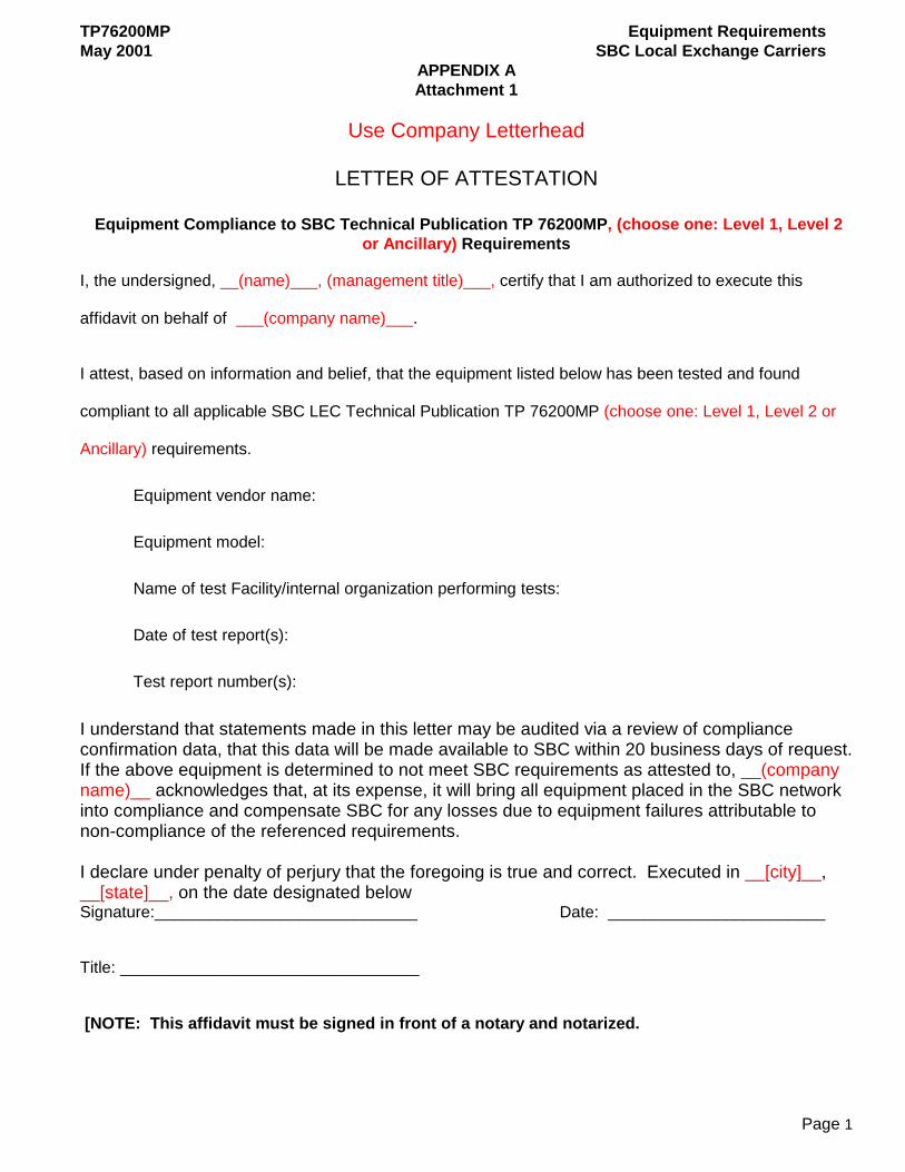
TP76200MP Equipment Requirements May 2001 SBC Local Exchange Carriers
APPENDIX A Attachment 1
Page 1
Use Company Letterhead
LETTER OF ATTESTATION
Equipment Compliance to SBC Technical Publication TP 76200MP, (choose one: Level 1, Level 2
or Ancillary) Requirements
I, the undersigned, __(name)___, (management title)___, certify that I am authorized to execute this
affidavit on behalf of ___(company name)___.
I attest, based on information and belief, that the equipment listed below has been tested and found
compliant to all applicable SBC LEC Technical Publication TP 76200MP (choose one: Level 1, Level 2 or
Ancillary) requirements.
Equipment vendor name:
Equipment model:
Name of test Facility/internal organization performing tests:
Date of test report(s):
Test report number(s):
I understand that statements made in this letter may be audited via a review of compliance confirmation data, that this data will be made available to SBC within 20 business days of request. If the above equipment is determined to not meet SBC requirements as attested to, __(company name)__ acknowledges that, at its expense, it will bring all equipment placed in the SBC network into compliance and compensate SBC for any losses due to equipment failures attributable to non-compliance of the referenced requirements. I declare under penalty of perjury that the foregoing is true and correct. Executed in __[city]__, __[state]__, on the date designated below Signature:_____________________________ Date: ________________________
Title: _________________________________
[NOTE: This affidavit must be signed in front of a notary and notarized.

TP76200MP Equipment Requirements May 2001 SBC Local Exchange Carriers
APPENDIX B
Page 1
TP 76200MP PRODUCT CHANGE
TEST GUIDELINES
1. PURPOSE The purpose of this appendix is to provide product suppliers a guide to help decide what tests may not need to be performed on a product enhancement to verify conformance to TP76200MP Ancillary requirements.
2. GENERAL Some product enhancements are so minor that a complete retest of the product may not be necessary. Typically, when a product supplier requests a re-test waiver to run tests on product enhancements, data comparing the new product to the existing product is submitted to the company representative for evaluation by SBC. Depending on the product under review, this data may include pictures, fire load data, descriptions of electrical components, etc. Each SBC product evaluation subject matter expert (SME) then reviews this data and responds with an assessment of what tests are required. This Appendix is intended to provide product suppliers with guidelines used by SBC to evaluate the need to test product enhancements. This Appendix only applies to product enhancements to equipment previously evaluated as in conformance to applicable TP 76200MP requirements and approved for use in SBC. This Appendix is intended as a guideline only. It is the product suppliers’ responsibility to satisfactorily document that the new product conforms to applicable requirements.
3. RETEST GUIDELINES BY TP 76200MP SECTIONS A. Section 2, Electromagnetic Compatibility Electromagnetic Interference – Emission & Immunity (TP76200MP Req. 2.04 – 2.09).
• Equipment suppliers should reassess or retest their equipment’s Emissions and Immunity performance in accordance with GR-1089 CORE, Section 3.4.7.
Lightning, AC Power Faults, Steady State Power Induction, Electrical Safety & DC Potential Difference (TP76200MP Req. 2.10 – 2.20).
• Equipment supplier’s should reassess or retest their equipment’s performance for Lightning, AC Power Faults, Steady State Power Induction, Electrical Safety & DC Potential Difference whenever materials, components, circuit layout or accessibility is changed. The equipment’s reassessment or retesting may include all of the technical requirements in these sections of TP76200MP. However, the reassessment or retesting is usually limited to only those technical requirements effected by the change in the equipment
B. Section 3, Acoustic Noise (TP76200MP Req. 3.01 – 3.03)
• Equipment suppliers should reassess or retest their equipment’s Acoustic Noise performance when a change is made to the equipment’s fan design, fan control system or a change in the number of fans within the equipment.
C. Section 4, ESD Subsystems should be tested whenever changes are introduced that may alter ESD susceptibility. Such changes may include a modified printed wiring board, new components or devices on the PWB, additional components or devices on the PWB and any new subsystem.
TP76200MP Equipment Requirements May 2001 SBC Local Exchange Carriers
APPENDIX B
Page 2
D. Section 5, Grounding Embedded ac or dc power supplies should be tested whenever changes are introduced that could alter the power supply short circuit tests. Such changes may include a modified printed wiring board, new components or devices on the PWB, additional components or devices on the PWB and any new power supply
E. Section 6, Thermal Temperature and Humidity
If the new product is significantly different from existing compliant products (e.g., different sub components, wiring, spacing, etc.) the previous test data may not be applicable to the new product. In order to be allowed to forego temperature and humidity testing on a new product, the product supplier needs to demonstrate to SBC that the new product is physically almost identical to the existing compliant product. This may be done via photographs, written descriptions, statements, etc. An example of an enhanced product that would not require retesting would be if the only physical change was a different memory chip. Heat Dissipation
Heat dissipation should be recalculated whenever a change is introduced that changes the power usage of the unit.
F. Section 7, DC Power The product supplier may perform an analysis, using good engineering judgement based on similarities to the existing product, predicting the probable conformance of the new product to Ancillary DC Power requirements. This analysis should consider similarities and differences of electric components, wiring, and power levels. The analysis shall be submitted to the company representative for review and approval by SBC.
G. Section 8, Airborne Contaminants: In reference to Airborne Contaminants testing, Telcordia GR-1274-CORE, states that “The qualification test shall be passed once for each new family of printed wiring assemblies.” Based on Telcordia’s assessment, new assemblies for enhanced products need not be tested for airborne contaminants if they meet the criteria for the same design family of printed boards, defined as follows:
A design family consists of printed wiring boards from the same manufacturer; using the same design rules for minimum line spacing and maximum electric field, and using components that require the same bias voltages. Within the same design family, boards shall have the same finish, i.e. they shall all be bare or all be coated with the same covercoat.
If the product supplier wishes to not test some or all of the printed wiring boards in an enhanced product, they shall supply a statement affirming that the board(s) not tested meet the definition for being in the same design family of a product previously approved for use in SBC. Documentation verifying the conformance of the tested card must be submitted for review. H. Section 9, Shock and Vibration Equipment should be tested whenever changes are introduced that could alter the physical integrity of the unit.
TP76200MP Equipment Requirements May 2001 SBC Local Exchange Carriers
APPENDIX B
Page 3
I. Section 10, Fire Resistance: Reasons for Reassessment
Products that have been determined to be acceptable for purchase from a fire resistance perspective do not have to be re-evaluated or retested unless subsequent changes to the product include one or more of the following: a) A change in the manufacturer's unique product identifier. b) A modification to an equipment assembly's enclosure that increases ambient air circulation. c) The addition of integral or separately mounted cooling fan(s) or a manufacture's requirement or
recommendation that fans be used with the equipment. d) The substitution of metallic apparatus with combustible material. e) A change in an equipment assembly's electrical protection circuitry that increases the ampere rating of
an overload protection device or affects the operational characteristics of a cooling fan. f) The addition of printed circuit board(s) to one or more existing printed circuit board. g) The addition of vertically oriented printed circuit boards to the extent that overall circuit board surface
area within the unit is increased by 300 cm2 (46.5 in.2).