erich industries | swing door openers | automatic door sensors - … 610... · 2019-02-04 ·...
TRANSCRIPT


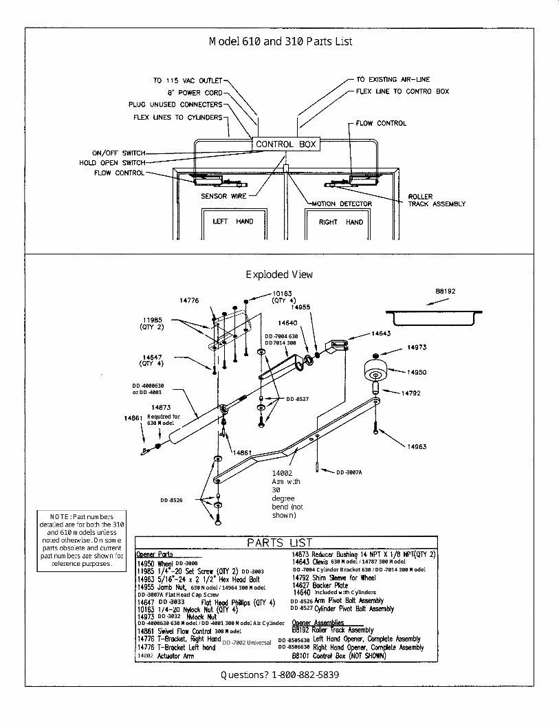
Erich Industries, Inc. AIR FORCE® AND DOOR DYNAMICS® DOOR OPENER
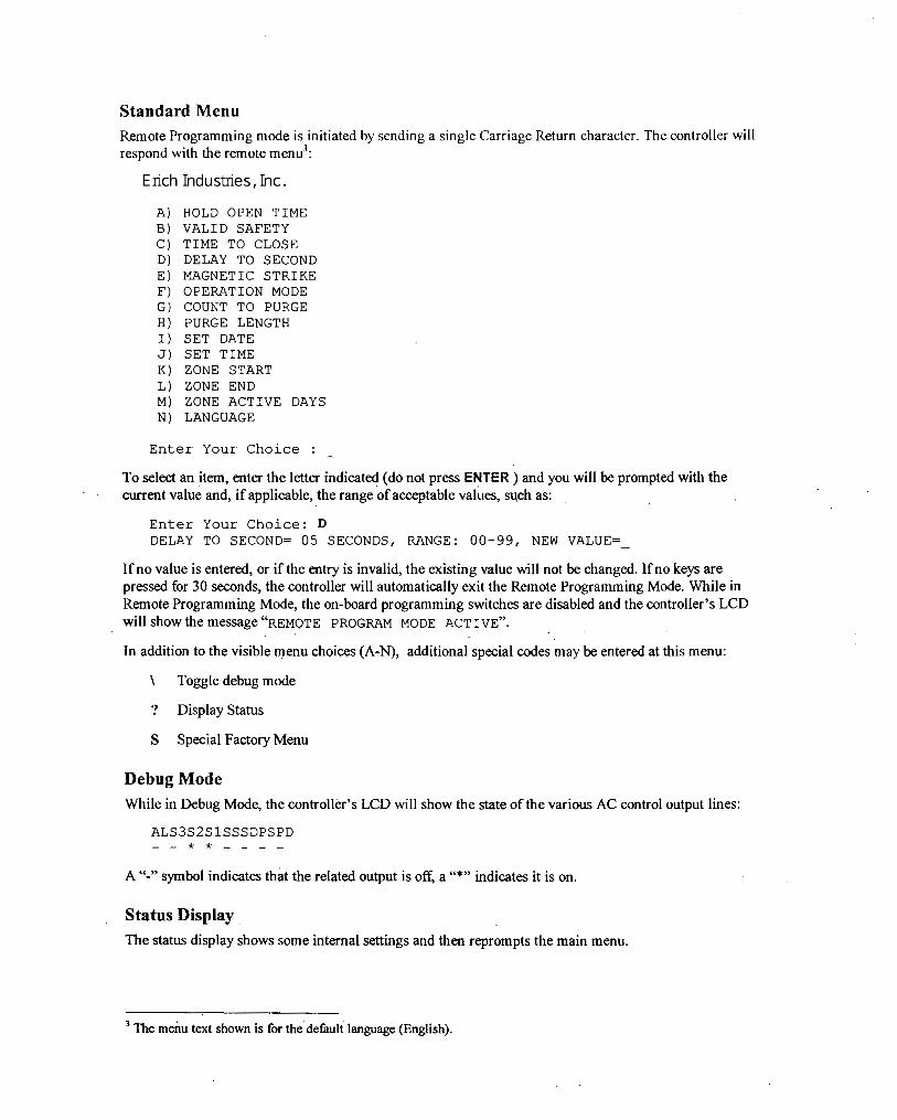
ELECTRICAL WIRING DETAILS Our control box is microprocessor based to insure maximum reliability and flexibility for the user. The system has been designed to be easy to set up and operate. Directions for setting the proper program are in the Circuit Board User’s Manual located elsewhere in this manual. The control unit is designed to be connected to a constant power source of 110VAC 60HZ or 230VAC 50HZ, which powers the control box and a wide variety of activation devices with 24VAC power. Activating devices and input signals should be connected directly to the terminal strip located on the left side of the control board. N = Power Common Lead N = Power Common Lead U = Unused - Auxiliary R = Remote Proof of Closure Signal S = Safety Signal I = Initiate Signal #1 = Unused - Auxiliary #2 = Unused - Auxiliary E = Unused - Auxiliary D = Safety Signal F = Fire Signal P = Proof of Closure Switch Signal H = 24V Power H = 24V Power Notes: Use Terminal strip connection to N and F to lock out opening if maglock is used and active. Door will remain in open position if receiving input from terminal strip D or S regardless of input from activation device. Below we provide wiring details for a variety of activation and safety devices available from Erich Industries. In most cases other manufacturer’s models can also be wired to the system in a similar fashion. Please consult with the manufacturer of that particular unit with questions or call us. E-2005 MS Sedco microStar Motion Detector E-3090 MS Sedco DH400 Presence Sensor
Red to H Red to H White to N Black to N Brown to I Yellow to S Black to N White to N
E-3060 MS Sedco GD11S Photoeye Safety Beam E-5010 MS Sedco 216 Touchless Switch Transmitter: White to H Red to H Black to N Green to N Receiver: White to H Red to N Black to N Blue to I Gray to D Green to N E-3070 BEA Microcell Photoeye Safety Beam E-5020 BEA MS-08 Touchless Switch #1 to H Red to H #2 to N Black to N
#3 to D White to N #4 to N Green to I
Cont.
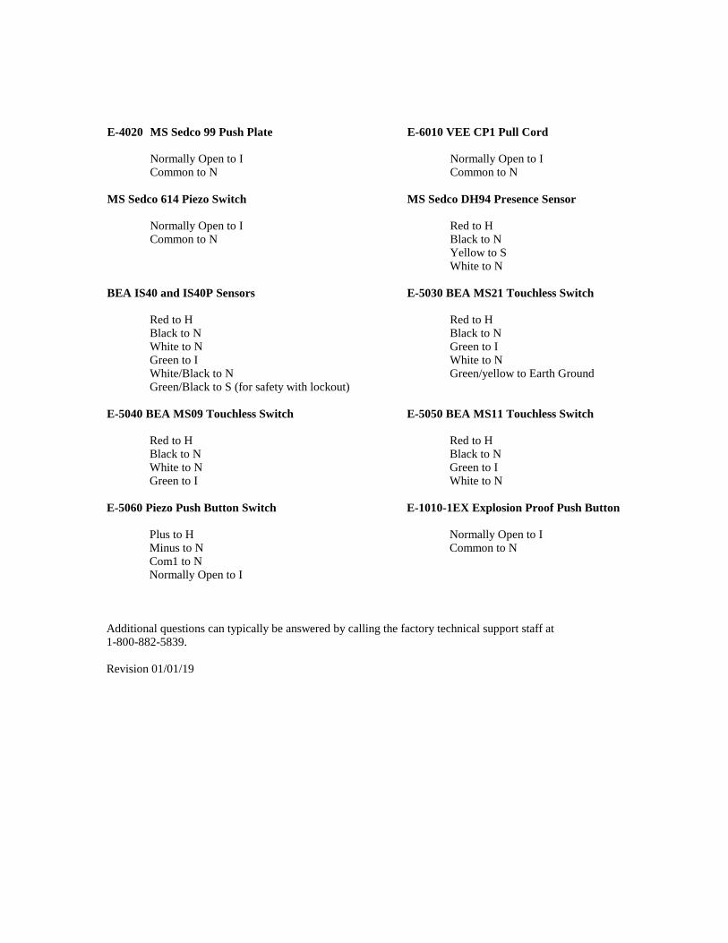
E-4020 MS Sedco 99 Push Plate E-6010 VEE CP1 Pull Cord Normally Open to I Normally Open to I Common to N Common to N MS Sedco 614 Piezo Switch MS Sedco DH94 Presence Sensor Normally Open to I Red to H Common to N Black to N Yellow to S White to N BEA IS40 and IS40P Sensors E-5030 BEA MS21 Touchless Switch Red to H Red to H Black to N Black to N White to N Green to I Green to I White to N White/Black to N Green/yellow to Earth Ground Green/Black to S (for safety with lockout) E-5040 BEA MS09 Touchless Switch E-5050 BEA MS11 Touchless Switch Red to H Red to H Black to N Black to N White to N Green to I Green to I White to N E-5060 Piezo Push Button Switch E-1010-1EX Explosion Proof Push Button Plus to H Normally Open to I Minus to N Common to N Com1 to N Normally Open to I Additional questions can typically be answered by calling the factory technical support staff at 1-800-882-5839. Revision 01/01/19


25 Section 4 - Operation
Erich IndustriesPerformance Products Division Phone 800/305-6736
550 N. Nine Mound Road Verona, WI 53593
OPERATING PROCEDURES FOR OPENERS
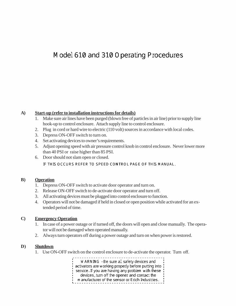
A) Start-up (refer to installation instructions for details)1. Make sure air lines have been purged (blown free of particles in air line) prior to supply line
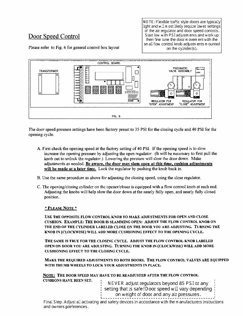
hook-up to control enclosure. Attach supply line to control enclosure.2. Plug in cord or hard wire to electric (110 volt) sources in accordance with local codes.3. Depress ON-OFF switch to turn on.4. Set activating devices to owner’s requirements.5. Adjust opening speed with air pressure control knob in control enclosure. Never lower more
than 40 PSI or raise higher than 85 PSI.6. Door should not slam open or closed. If this occurs, increase the back check on the door
closer to a cushioned stop at the end of the cycle. Adjust the latch check on the closer for acushioned close at the end of the closing cycle.
B) Operation1. Depress ON-OFF switch to activate door operator and turn on.2. Release ON-OFF switch to de-activate door operator and turn off.3. All activating devices must be plugged into control enclosure to function.4. Operators will not be damaged if held in closed or open position while activated for an ex-
tended period of time.
C) Emergency Operation1. In case of a power outage or if turned off, the doors will open and close manually. The opera-
tor will not be damaged when operated manually.2. Always turn operators off during a power outage and turn on when power is restored.
D) Shutdown1. Use ON-OFF switch on the control enclosure to de-activate the operator. Turn off.

26Section 5 - Maintenance
Erich IndustriesPerformance Products Division Phone 800/305-6736
550 N. Nine Mound Road Verona, WI 53593
MAINTENANCE PROCEDURES FOR “KWIK-OP”
A) Maintenance - Air Source (as applicable)1. Service compressors, filters, etc. as per manufacturer’s instructions.2. Service should be carried out in 3 month intervals, or as required. Consult this manual for
details.
B) Maintenance - Operators1. Manually open doors to check for “free swing”. Adjust and/or lubricate hinges.2. Check actuator arms for excessive play. If required, loosen set screw or lock nut and tighten
bolt to remove play. Do not over tighten, which will cause binding. After tightening set screwor lock nut, check again to insure that the unit has free action.
3. Check cylinder jamb nut and tighten (if required) with the cylinder vent on the bottom.4. Lubricate bearing points with spray lube.5. Check air filter on supply air line. Clean, drain, or replace as required.6. Check, air hoses and connections for leaks, kinks, or contact with moving parts. Correct as
required.7. Check air pressure and opening speed. Adjust per instructions as required.8. Check closer back check, closing speed, and latch speed. Adjust per instructions as required.9. Check Time Delay period. Adjust per instructions as required.
10. Service should be carried out in 3 month intervals along with compressor servicing, or as required.