erl operation of s-dalinac - kek
TRANSCRIPT
ERL OPERATION OF S-DALINAC∗
M. Arnold†, T. Bahlo, M. Dutine, R. Grewe, J. Hanten, L. Jürgensen, J. Pforr, N. Pietralla,F. Schließmann, M. Steinhorst, S. Weih, Technische Universität Darmstadt, Darmstadt, Germany
AbstractThe S-DALINAC is a thrice-recirculating superconduct-
ing electron accelerator which can be either used in conven-tional accelerating operation or, since a major upgrade wasinstalled in 2015/2016, as an energy recovery linac (ERL)alternatively. A once- or twice-recirculating ERL operationis possible due to the layout of the accelerator. During thecommissioning phase the once-recirculating ERL operationwas demonstrated in August 2017. Measurement data andan analytical model for the radio-frequency power behaviourdue to changes in the beam loading are presented.
INTRODUCTIONThe material discussed in this oral presentation is based
upon the content of a scientific article which we have submit-ted on 4th of October 2019 to Physical Review Acceleratorsand Beams. Our present contribution to these conferenceproceedings, hence, contains descriptions of our work in theway which we were able to formulate them best.
S-DALINACThe S-DALINAC is in operation since 1991 at TU Darm-
stadt [1]. A floorplan is shown in Fig. 1.
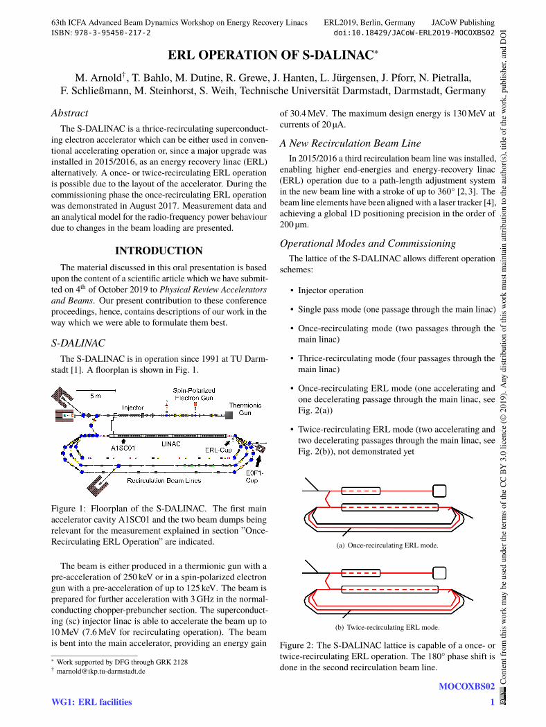
Figure 1: Floorplan of the S-DALINAC. The first mainaccelerator cavity A1SC01 and the two beam dumps beingrelevant for the measurement explained in section ”Once-Recirculating ERL Operation” are indicated.
The beam is either produced in a thermionic gun with apre-acceleration of 250 keV or in a spin-polarized electrongun with a pre-acceleration of up to 125 keV. The beam isprepared for further acceleration with 3 GHz in the normal-conducting chopper-prebuncher section. The superconduct-ing (sc) injector linac is able to accelerate the beam up to10 MeV (7.6 MeV for recirculating operation). The beamis bent into the main accelerator, providing an energy gain
∗ Work supported by DFG through GRK 2128† [email protected]
of 30.4 MeV. The maximum design energy is 130 MeV atcurrents of 20 µA.
A New Recirculation Beam LineIn 2015/2016 a third recirculation beam line was installed,
enabling higher end-energies and energy-recovery linac(ERL) operation due to a path-length adjustment systemin the new beam line with a stroke of up to 360° [2, 3]. Thebeam line elements have been aligned with a laser tracker [4],achieving a global 1D positioning precision in the order of200 µm.
Operational Modes and CommissioningThe lattice of the S-DALINAC allows different operation
schemes:
• Injector operation
• Single pass mode (one passage through the main linac)
• Once-recirculating mode (two passages through themain linac)
• Thrice-recirculating mode (four passages through themain linac)
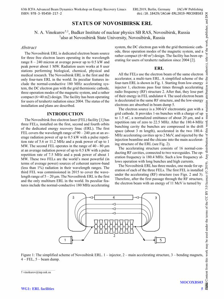
• Once-recirculating ERL mode (one accelerating andone decelerating passage through the main linac, seeFig. 2(a))
• Twice-recirculating ERL mode (two accelerating andtwo decelerating passages through the main linac, seeFig. 2(b)), not demonstrated yet
(a) Once-recirculating ERL mode.
(b) Twice-recirculating ERL mode.
Figure 2: The S-DALINAC lattice is capable of a once- ortwice-recirculating ERL operation. The 180° phase shift isdone in the second recirculation beam line.
63th ICFA Advanced Beam Dynamics Workshop on Energy Recovery Linacs ERL2019, Berlin, Germany JACoW PublishingISBN: 978-3-95450-217-2 doi:10.18429/JACoW-ERL2019-MOCOXBS02
WG1: ERL facilitiesMOCOXBS02
1
Cont
entf
rom
this
wor
km
aybe
used
unde
rthe
term
soft
heCC
BY3.
0lic
ence
(©20
19).
Any
distr
ibut
ion
ofth
isw
ork
mus
tmai
ntai
nat
tribu
tion
toth
eau
thor
(s),
title
ofth
ew
ork,
publ
isher
,and
DO
I
STATUS OF NOVOSIBIRSK ERL
N. A. Vinokurov†,1, Budker Institute of nuclear physics SB RAS, Novosibirsk, Russia 1also at Novosibirsk State University, Novosibirsk, Russia
Abstract The Novosibirsk ERL is dedicated electron beam source
for three free electron lasers operating in the wavelength range 8 – 240 micron at average power up to 0.5 kW and peak power about 1 MW. Radiation users works at 8 user stations performing biological, chemical, physical and medical research. The Novosibirsk ERL is the first and the only four-turn ERL in the world. Its peculiar features in-clude the normal-conductive 180 MHz accelerating sys-tem, the DC electron gun with the grid thermionic cathode, three operation modes of the magnetic system, and a rather compact (6×40 m2) design. The facility has been operating for users of terahertz radiation since 2004. The status of the installation and plans are described.
INTRODUCTION The Novosibirsk free electron laser (FEL) facility [1] has
three FELs, installed on the first, second and fourth orbits of the dedicated energy recovery linac (ERL). The first FEL covers the wavelength range of 90 – 240 μm at an av-erage radiation power of up to 0.5 kW with a pulse repeti-tion rate of 5.6 or 11.2 MHz and a peak power of up to 1 MW. The second FEL operates in the range of 40 - 80 μm at an average radiation power of up to 0.5 kW with a pulse repetition rate of 7.5 MHz and a peak power of about 1 MW. These two FELs are the world’s most powerful (in terms of average power) sources of coherent narrow-band (less than 1%) radiation in their wavelength ranges. The third FEL was commissioned in 2015 to cover the wave-length range of 5 – 20 μm. The Novosibirsk ERL is the first and the only multiturn ERL in the world. Its peculiar fea-tures include the normal-conductive 180 MHz accelerating
system, the DC electron gun with the grid thermionic cath-ode, three operation modes of the magnetic system, and a rather compact (6×40 m2) design. The facility has been op-erating for users of terahertz radiation since 2004 [2].
ERL All the FELs use the electron beam of the same electron
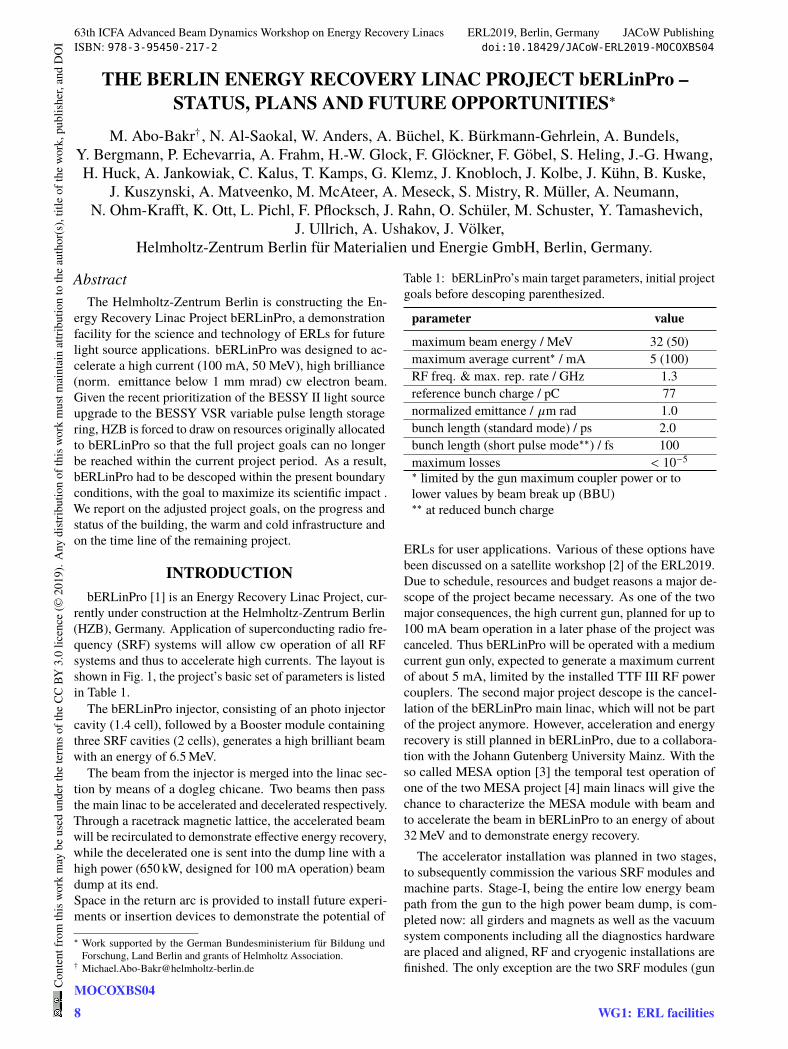
accelerator, a multi-turn ERL. A simplified scheme of the four-turn ERL is shown in Fig. 1. Starting from low-energy injector 1, electrons pass four times through accelerating radio frequency (RF) structure 2. After that, they lose part of their energy in FEL undulator 4. The used electron beam is decelerated in the same RF structure, and the low-energy electrons are absorbed in beam dump 5.
The electron source is a 300-kV electrostatic gun with a grid cathode. It provides 1-ns bunches with a charge of up to 1.5 nC, a normalized emittance of about 20 μm, and a repetition rate of zero to 22.5 MHz. After the 180.4-MHz bunching cavity the bunches are compressed in the drift space (about 3 m length), accelerated in the two 180.4-MHz accelerating cavities up to 2 MeV, and injected by the injection beamline and the chicane into the main accelerat-ing structure of the ERL (see Fig. 2).
The accelerating structure consists of 16 normal-con-ducting RF cavities, connected to two waveguides. The op-eration frequency is 180.4 MHz. Such a low frequency al-lows operation with long bunches and high currents.
The Novosibirsk ERL has three modes, one mode for op-eration of each of the three FELs. The first FEL is installed under the accelerating (RF) structure (see Figs. 2 and 3). Therefore, after the first passage through the RF structure, the electron beam with an energy of 11 MeV is turned by
Figure 1: The simplified scheme of Novosibirsk ERL. 1 – injector, 2 – main accelerating structure, 3 – bending magnets, 4 – FEL, 5 – beam dump.
____________________________________________
63th ICFA Advanced Beam Dynamics Workshop on Energy Recovery Linacs ERL2019, Berlin, Germany JACoW PublishingISBN: 978-3-95450-217-2 doi:10.18429/JACoW-ERL2019-MOCOXBS03
WG1: ERL facilitiesMOCOXBS03
5
Cont
entf
rom
this
wor
km
aybe
used
unde
rthe
term
soft
heCC
BY3.
0lic
ence
(©20
19).
Any
distr
ibut
ion
ofth
isw
ork
mus
tmai
ntai
nat
tribu
tion
toth
eau
thor
(s),
title
ofth
ew
ork,
publ
isher
,and
DO
I
THE BERLIN ENERGY RECOVERY LINAC PROJECT bERLinPro –STATUS, PLANS AND FUTURE OPPORTUNITIES∗
M. Abo-Bakr† , N. Al-Saokal, W. Anders, A. Büchel, K. Bürkmann-Gehrlein, A. Bundels,Y. Bergmann, P. Echevarria, A. Frahm, H.-W. Glock, F. Glöckner, F. Göbel, S. Heling, J.-G. Hwang,H. Huck, A. Jankowiak, C. Kalus, T. Kamps, G. Klemz, J. Knobloch, J. Kolbe, J. Kühn, B. Kuske,
J. Kuszynski, A. Matveenko, M. McAteer, A. Meseck, S. Mistry, R. Müller, A. Neumann,N. Ohm-Krafft, K. Ott, L. Pichl, F. Pflocksch, J. Rahn, O. Schüler, M. Schuster, Y. Tamashevich,
J. Ullrich, A. Ushakov, J. Völker,Helmholtz-Zentrum Berlin für Materialien und Energie GmbH, Berlin, Germany.
AbstractThe Helmholtz-Zentrum Berlin is constructing the En-
ergy Recovery Linac Project bERLinPro, a demonstrationfacility for the science and technology of ERLs for futurelight source applications. bERLinPro was designed to ac-celerate a high current (100 mA, 50 MeV), high brilliance(norm. emittance below 1 mm mrad) cw electron beam.Given the recent prioritization of the BESSY II light sourceupgrade to the BESSY VSR variable pulse length storagering, HZB is forced to draw on resources originally allocatedto bERLinPro so that the full project goals can no longerbe reached within the current project period. As a result,bERLinPro had to be descoped within the present boundaryconditions, with the goal to maximize its scientific impact .We report on the adjusted project goals, on the progress andstatus of the building, the warm and cold infrastructure andon the time line of the remaining project.
INTRODUCTIONbERLinPro [1] is an Energy Recovery Linac Project, cur-
rently under construction at the Helmholtz-Zentrum Berlin(HZB), Germany. Application of superconducting radio fre-quency (SRF) systems will allow cw operation of all RFsystems and thus to accelerate high currents. The layout isshown in Fig. 1, the project’s basic set of parameters is listedin Table 1.The bERLinPro injector, consisting of an photo injector
cavity (1.4 cell), followed by a Booster module containingthree SRF cavities (2 cells), generates a high brilliant beamwith an energy of 6.5MeV.The beam from the injector is merged into the linac sec-
tion by means of a dogleg chicane. Two beams then passthe main linac to be accelerated and decelerated respectively.Through a racetrack magnetic lattice, the accelerated beamwill be recirculated to demonstrate effective energy recovery,while the decelerated one is sent into the dump line with ahigh power (650 kW, designed for 100 mA operation) beamdump at its end.Space in the return arc is provided to install future experi-ments or insertion devices to demonstrate the potential of
∗ Work supported by the German Bundesministerium für Bildung undForschung, Land Berlin and grants of Helmholtz Association.
Table 1: bERLinPro’s main target parameters, initial projectgoals before descoping parenthesized.
parameter value
maximum beam energy / MeV 32 (50)maximum average current∗ / mA 5 (100)RF freq. & max. rep. rate / GHz 1.3reference bunch charge / pC 77normalized emittance / 𝜇m rad 1.0bunch length (standard mode) / ps 2.0bunch length (short pulse mode∗∗) / fs 100maximum losses < 10−5∗ limited by the gun maximum coupler power or tolower values by beam break up (BBU)∗∗ at reduced bunch charge
ERLs for user applications. Various of these options havebeen discussed on a satellite workshop [2] of the ERL2019.Due to schedule, resources and budget reasons a major de-scope of the project became necessary. As one of the twomajor consequences, the high current gun, planned for up to100 mA beam operation in a later phase of the project wascanceled. Thus bERLinPro will be operated with a mediumcurrent gun only, expected to generate a maximum currentof about 5 mA, limited by the installed TTF III RF powercouplers. The second major project descope is the cancel-lation of the bERLinPro main linac, which will not be partof the project anymore. However, acceleration and energyrecovery is still planned in bERLinPro, due to a collabora-tion with the Johann Gutenberg University Mainz. With theso called MESA option [3] the temporal test operation ofone of the two MESA project [4] main linacs will give thechance to characterize the MESA module with beam andto accelerate the beam in bERLinPro to an energy of about32MeV and to demonstrate energy recovery.The accelerator installation was planned in two stages,
to subsequently commission the various SRF modules andmachine parts. Stage-I, being the entire low energy beampath from the gun to the high power beam dump, is com-pleted now: all girders and magnets as well as the vacuumsystem components including all the diagnostics hardwareare placed and aligned, RF and cryogenic installations arefinished. The only exception are the two SRF modules (gun
63th ICFA Advanced Beam Dynamics Workshop on Energy Recovery Linacs ERL2019, Berlin, Germany JACoW PublishingISBN: 978-3-95450-217-2 doi:10.18429/JACoW-ERL2019-MOCOXBS04
MOCOXBS048
Cont
entf
rom
this
wor
km
aybe
used
unde
rthe
term
soft
heCC
BY3.
0lic
ence
(©20
19).
Any
distr
ibut
ion
ofth
isw
ork
mus
tmai
ntai
nat
tribu
tion
toth
eau
thor
(s),
title
ofth
ew
ork,
publ
isher
,and
DO
I
WG1: ERL facilities
STATUS OF THE MESA ERL-PROJECT*
F. Hug†, K. Aulenbacher1, S. Friederich, P. Heil, R.G. Heine, R. Kempf, C. Matejcek, D. Simon Johannes Gutenberg-Universität Mainz, Mainz, Germany
1also at Helmholtz Institut Mainz, Germany and GSI Helmholtzzentrum für Schwerionenforschung, Darmstadt, Germany
Abstract MESA is a recirculating superconducting accelerator un-
der construction at Johannes Gutenberg-Universität Mainz. It can be operated in either external beam or ERL mode and will be used for high precision particle physics experi-ments. The operating cw beam current and energy in EB mode is 0.15 mA with polarized electrons at 155 MeV. In ERL mode a polarized beam of 1 mA at 105 MeV will be available. In a later construction stage of MESA the beam current in ERL-mode shall be upgraded to 10 mA (unpo-larized). Civil construction and commissioning of compo-nents like electron gun, LEBT and SRF modules have been started already. We will give a project overview including the accelerator layout, the current status and an outlook to the next construction and commissioning steps.
INTRODUCTION The Mainz Energy-recovering Superconducting Accel-
erator (MESA) (layout see Fig. 1) will be a low energy con-tinuous wave (cw) recirculating electron linac for particle
and nuclear physics experiments. In the first phase of op-eration it will serve mainly three experiments.
The main experiment of MESA, run in external beam (EB) mode, where the beam needs to be dumped after be-ing used, will be the fixed target setup P2 [1], whose goal is the measurement of the weak mixing angle (Weinberg angle) by measuring parity violation asymmetry with high-est accuracy. Required beam current for P2 is 150 μA with spin-polarized electrons at a maximum energy of 155 MeV.
Additionally, a so called beam-dump experiment (BDX) is planned to run in parallel to P2 [2]. This experiment will be located outside of the accelerator hall in line with the beam dump and is dedicated for searching dark particles, which might be generated dumping the beam of the P2 ex-periment, benefiting from the massive radiation shielding of the dump, which reduces background to a minimum. The third experimental setup will be the high resolution two-arm spectrometer facility MAGIX [3], which uses a gas jet target [4] and can be run in ERL mode.
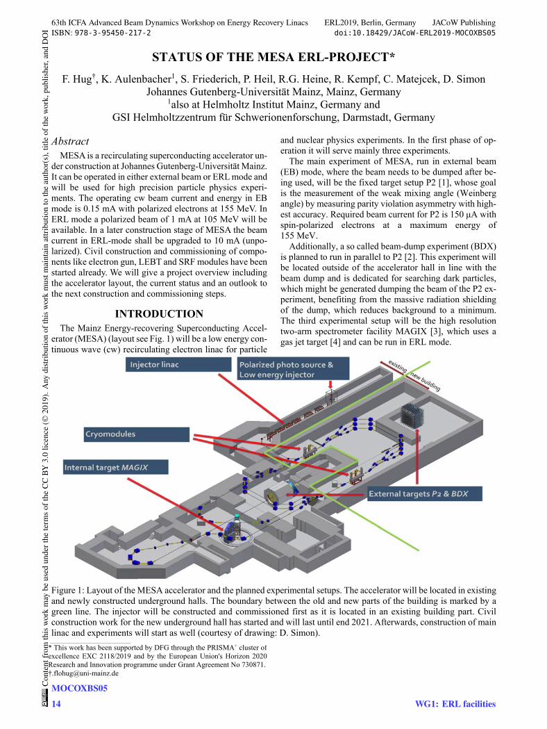
Figure 1: Layout of the MESA accelerator and the planned experimental setups. The accelerator will be located in existing and newly constructed underground halls. The boundary between the old and new parts of the building is marked by a green line. The injector will be constructed and commissioned first as it is located in an existing building part. Civil construction work for the new underground hall has started and will last until end 2021. Afterwards, construction of main linac and experiments will start as well (courtesy of drawing: D. Simon).
___________________________________________
* This work has been supported by DFG through the PRISMA+ cluster of excellence EXC 2118/2019 and by the European Union's Horizon 2020Research and Innovation programme under Grant Agreement No 730871.†[email protected]
63th ICFA Advanced Beam Dynamics Workshop on Energy Recovery Linacs ERL2019, Berlin, Germany JACoW PublishingISBN: 978-3-95450-217-2 doi:10.18429/JACoW-ERL2019-MOCOXBS05
MOCOXBS0514
Cont
entf
rom
this
wor
km
aybe
used
unde
rthe
term
soft
heCC
BY3.
0lic
ence
(©20
19).
Any
distr
ibut
ion
ofth
isw
ork
mus
tmai
ntai
nat
tribu
tion
toth
eau
thor
(s),
title
ofth
ew
ork,
publ
isher
,and
DO
I
WG1: ERL facilities

ELECTRODISINTEGRATION OF 16O AND THE RATEDETERMINATION OF THE RADIATIVE 𝜶 CAPTURE ON 12C AT
STELLAR ENERGIESI. Friščić ∗, T. W. Donnelly, R. G. Milner
Massachusetts Institute of Technology, Cambridge, Massachusetts 02139, USA
AbstractFor over five decades one of the most important goals of
experimental nuclear astrophysics has been to reduce theuncertainty in the S-factor of radiative 𝛼 capture on 12C atstellar energies. We have developed a simple model, whichrelates the radiative capture reaction and the exclusive elec-trodisintegration reaction. We then show that by measuringthe rate of electrodisintegration of 16O in a high luminosityexperiment using a state-of-the-art jet-target and a new gener-ation of energy-recovery linear (ERL) electron acceleratorsunder development, it is possible to significantly improvethe statistical uncertainty of the radiative 𝛼 capture on 12C interms of E1 and E2 S-factors in the astrophysically interest-ing region, which are the key inputs for any nucleosynthesisand stellar evolution models. The model needs to be vali-dated experimentally, but, if successful, it can be used toimprove the precision of other astrophysically-relevant, ra-diative capture reactions, thus opening a significant avenueof research that spans nuclear structure, astrophysics andhigh-power accelerator technology.
INTRODUCTIONDuring the stellar evolution, the helium burning stage is
dominated by two reactions: radiative triple-𝛼 capture andradiative 𝛼 capture on 12C, i.e. 12C(𝛼, 𝛾)16O. The values ofthe individual rates will determine the 12C/16O abundance atthe end of the helium burning stage, which highly influencesthe subsequent nucleosynthesis [1]. The current uncertaintyin triple-𝛼 capture at stellar energies is known with an uncer-tainty of ∼10%, but for the 12C(𝛼, 𝛾)16O rate the situation ismuch worse [2]. In the modeling of the stellar evolution, thelarge uncertainty of the measured 12C(𝛼, 𝛾)16O rate trans-lates into large range of rates and because of this models givedifferent outcomes in terms of nuclei abundance inside a starof a given mass [1, 2]. Thus, for many decades, the goal ofexperimental nuclear physics was to improve the precisionof measurements of the 12C(𝛼, 𝛾)16O rate at stellar energies[3]. Attempts were made to constrain the 12C(𝛼, 𝛾)16O rateusing the models and the observed solar abundances [1],implicating that the experimental rate needs to be measuredwith an uncertainty ≤10% [4]. Such a level of precision hasstill not been achieved..
At typical helium burning temperature for massive stars∼2·108 K, the equivalent Gamow energy 𝐸𝑔 is ∼300 keVand due to large Coulomb barrier the cross section of the12C(𝛼, 𝛾)16O reaction is extremely small ∼10−5 pb, making∗ [email protected]
the direct measurements infeasible. The strategy is to mea-sure the cross section, which is usually expressed in terms ofthe astrophysical S-factor as a function of 𝛼-particle center-of-mass (𝑐𝑚) kinetic energy 𝐸𝑐𝑚𝛼 :
𝑆 = 𝜎𝐸𝑐𝑚𝛼 𝑒2𝜋` (1)
where ` is the Sommerfeld parameter, at several larger en-ergies and then to extrapolate to stellar energies. The ex-trapolation is complicated due the structure of 16O [5] andinvolves dealing with the interference of subthreshold andabove threshold E1/E2 states.
In the past, many different experimental methods havebeen developed and used to measure the 12C(𝛼, 𝛾)16O rate,including the direct reaction measurements [6–19], elasticscattering 12C(𝛼, 𝛼)12C [20, 21], and 𝛽−delayed 𝛼-decayof 16N [22–24]. Below 𝐸𝑐𝑚𝛼 < 2 MeV the data points areincreasingly dominated by the statistical uncertainties, dueto rapidly falling of the cross section as it approaches theGamow energy. Recently, researchers have started to in-vestigate the inverse reaction induced by real photons (thephotodisintegration of 16O), in order to improve the statis-tics of low-energy data. One concept uses a bubble chamber[25, 26] and the other an optical time projection chamber[27]. More details about the specific experiments and theastrophysical implications of the 12C(𝛼, 𝛾)16O rate can befound in the most recent review [2].
Contrary to photodisintegration, where the real photonbeam is involved | ®𝑞 | = 𝑞 = 𝐸𝛾 , the electrodisintegration usesan electron beam with an exchange of a virtual photon (𝜔, ®𝑞),for details see [28]. In the past, the potential astrophysicalapplication of the electrodisintegration of 16O was discussedin [29] and an storage ring based experiment was proposed in[30], but was never carried out. More recent discussions [31,32] are motivated by development of a new generation ofhigh intensity (≈ 10 mA) low-energy (≈ 100 MeV) energy-recovery linear (ERL) electron accelerators [33, 34] andwhich together with modern jet gas targets [35], can deliverluminosity >1035 cm−2 s−1. By measuring the final stateof the scattered electron it is possible to define and fix the𝛼+12C excitation energy, but at the same time control thethree-momentum of the virtual photon ®𝑞 either by selectingthe electron scattering angle \𝑒 or the beam energy 𝐸𝑒, seeFig 1. The real photon result can be recovered by taking thelimit 𝑞/𝜔 → 1.
In this paper, we briefly present a new method to improvethe precision of the 12C(𝛼, 𝛾)16O reaction at stellar energiesbased on electrodisintegration of 16O, i.e. 16O(𝑒, 𝑒′𝛼)16C.The full description of this method can be found in [36].
63th ICFA Advanced Beam Dynamics Workshop on Energy Recovery Linacs ERL2019, Berlin, Germany JACoW PublishingISBN: 978-3-95450-217-2 doi:10.18429/JACoW-ERL2019-MOCOYBS04
MOCOYBS0418
Cont
entf
rom
this
wor
km
aybe
used
unde
rthe
term
soft
heCC
BY3.
0lic
ence
(©20
19).
Any
distr
ibut
ion
ofth
isw
ork
mus
tmai
ntai
nat
tribu
tion
toth
eau
thor
(s),
title
ofth
ew
ork,
publ
isher
,and
DO
I
WG5: ERL applications
BEAM HALO IN ENERGY RECOVERY LINACS
O. A. Tanaka†, High Energy Accelerator Research Organization (KEK), Tsukuba, Japan
Abstract The beam halo mitigation is a very important challenge
for reliable and safe operation of a high energy machine. Since Energy Recovery Linacs (ERLs) are known to produce high energy electron beams of high virtual power and high density, the beam halo and related beam losses should be properly mitigated to avoid a direct damage of the equipment, an unacceptable increase in the vacuum pressure, a radiation activation of the accelerator compo-nents etc. To keep the operation stable, one needs to ad-dress all possible beam halo formation mechanisms, in-cluding those unique to each machine that can generate beam halo. Present report is dedicated to the beam halo related activities at the Compact ERL at KEK, and our operational experience with respect to the beam halo.
INTRODUCTION
Beam halo studies and halo mitigation schemes are of the great importance at each stage of accelerator R&D. For those machines that are at their design stage, beam halo studies are limited simply by the absence of the real equipment to perform some tests. Nevertheless, several halo formation mechanisms and processes impacting into the halo could be modeled and estimated prior the ma-chine construction. Here are some of them: A space charge effect causes emittance blow-up and
bunch lengthening that finally could lead to the for-mation of the beam halo and consequent beam losses. Examples of space charge effect studies for ERL ma-chines could be found in [1] – [4]. Effects of the CSR (Coherent Synchrotron Radia-tion). CSR related issues are in trend nowadays, and addressed in numerous studies (see, for example, [4] – [5]). Dark current from the electron gun and longitudinal bunch tails originated at the photocathode [6] – [7].
Other mechanisms could be studied only after the ma-chine construction. One of the examples of the processes enhancing the halo that could not be investigated before-hand is a dark current from RF cavities. Recent results could be found in [8]. Another example is those halo formation mechanisms that are unique for each machine. Thus at the Compact ERL (cERL) at KEK such a unique process was detected and explained for the essential verti-cal beam halo observed in the end of the injector section and at several locations of the recirculation loop [9]. However, this study was done for the low bunch charge operation (1 pC/bunch, [10]), while the next step opera-tional goal was to achieve a high bunch charge operation (60 pC/bunch, [11]).
Recent industrialization of the cERL beam line [12]
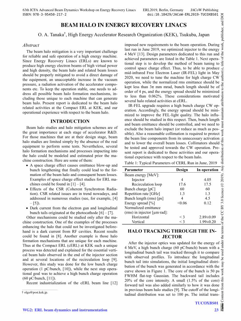
imposed new requirements to the beam operation. During last run in June 2019, we optimized injector to the energy 4 MeV [13]. Design parameters dedicated to this run and achieved parameters are listed in the Table 1. Next opera-tional step is to develop the method of beam tuning to control space charge effect. Thus, to be able to produce mid-infrared Free Electron Laser (IR-FEL) light in May 2020, we need to tune the machine for high charge CW operation, while the normalized rms emittance should be kept less than 3π mm mrad, bunch length should be of order of 4 ps, and the energy spread should be minimized to less than 0.062%. These considerations motivated several halo related activities at cERL.
IR-FEL upgrade requires a high bunch charge CW op-eration. Accordingly, the energy spread should be mini-mized to improve the FEL-light quality. The halo influ-ence should be studied in this respect. Then, bunch length and beam emittance should be controlled, and we need to exclude the beam halo impact (or reduce as much as pos-sible). Also a reasonable collimation is required to protect the beam line components from its unnecessary activation and to lower the overall beam losses. Collimators should be tested and approved towards the CW operation. Pre-sent report is dedicated to these activities and our opera-tional experience with respect to the beam halo. Table 1: Typical Parameters of CERL Run in June, 2019
Parameter Design In operation
Beam energy [MeV]: Injector
Recirculation loop
4
17.6
4.05
17.5
Bunch charge [pC] 60 60
Repetition rate [GHz] 1.3 1.3
Bunch length (rms) [ps] 4 4.5
Energy spread [%] <0.06 0.12
Normalized emittance (rms) in injector [µm∙rad]:
Horizontal Vertical
< 3
< 3
2.89±0.09 1.99±0.20
HALO TRACKING THROUGH THE IN-JECTOR
After the injector optics was updated for the energy of 4 MeV, a high bunch charge (60 pC/bunch) beam with a longitudinal bunch tail was tracked through it to compare with observed profiles. To introduce the longitudinal bunch tail into simulations, the initial longitudinal distri-bution of the bunch was generated in accordance with the curve shown in Figure 1. The core of the bunch is 50 ps FWHM flat-top Gaussian. The backward tail includes 20% of the core intensity. A small (1.5% of the core) forward tail was also added similarly to how it was done in previous beam halo studies [9]. The cutoff of the longi-tudinal distribution was set to 100 ps. The initial trans-
___________________________________________
63th ICFA Advanced Beam Dynamics Workshop on Energy Recovery Linacs ERL2019, Berlin, Germany JACoW PublishingISBN: 978-3-95450-217-2 doi:10.18429/JACoW-ERL2019-TUCOXBS01
WG2: ERL beam dynamics and instrumentationTUCOXBS01
23
Cont
entf
rom
this
wor
km
aybe
used
unde
rthe
term
soft
heCC
BY3.
0lic
ence
(©20
19).
Any
distr
ibut
ion
ofth
isw
ork
mus
tmai
ntai
nat
tribu
tion
toth
eau
thor
(s),
title
ofth
ew
ork,
publ
isher
,and
DO
I
BEAM DYNAMICS LAYOUT OF THE MESA ERL*
F. Hug†, K. Aulenbacher1, D. Simon, C.P. Stoll, S.D.W. Thomas Johannes Gutenberg-Universität Mainz, Mainz, Germany
1also at Helmholtz Institut Mainz, Germany and GSI Helmholtzzentrum für Schwerionenforschung, Darmstadt, Germany
Abstract The MESA project is currently under construction at Jo-
hannes Gutenberg-Universität Mainz. It will be used for high precision particle physics experiments in two different operation modes: external beam (EB) mode (0.15 mA; 155 MeV) and energy recovery (ERL) mode (1 mA; 105 MeV). The recirculating main linac follows the con-cept of a double sided accelerator design with vertical stacking of return arcs. Up to three recirculations are pos-sible. Acceleration is done by four TESLA/XFEL 9-cell SRF cavities located in two modified ELBE cryomodules. Within this contribution the recirculation optics for MESA will be presented. Main goals are achieving best energy spread at the experimental setups in recirculating ERL and non-ERL operation and providing small beta-functions within the cryomodules for minimizing HOM excitation at high beam currents.
INTRODUCTION The Mainz Energy-recovering Superconducting Accel-
erator (MESA) is a low energy continuous wave (cw) re-circulating electron linac for particle and nuclear physics experiments under construction at Johannes Gutenberg-Universität Mainz [1-3]. The first phase of operation fore-sees to serve mainly three experiments, two of them run-ning in external beam mode (EB) and one in energy recov-ering mode (ERL). MESA construction was funded in 2012. The facility and its experiments [4-6] have under-gone several design changes since then. The latest change of layout has been applied in spring 2019 and was pre-sented already in [7]. Therefore, start to end tracking sim-ulations for the complete machine [8] are still based on an older layout version and need to be repeated for the new one. Nevertheless, the main design of MESA has been kept up throughout the changes of accelerator layout. MESA will be constructed in a double sided accelerator layout with two superconducting linacs and vertically stacked re-turn arcs. In EB mode, up to three linac passes are possible and maximum beam energy and current yield 155 MeV and 150 µA respectively. In ERL operation only two passes can be used for acceleration and after experimental use of the beam for deceleration again. The maximum beam energy reduces to 105 MeV but the maximum beam current is not limited by installed rf power anymore and can go up to 1 mA. In a later stage of MESA operation, the beam current
shall be increased to the maximum available current from the injector linac (10 mA) [9].
All MESA experiments rely on excellent beam quality in order to perform precision experiments on nuclear and particle physics searching for dark particles and beyond standard model physics. Therefore, a relative energy spread of the beam of approx. 10-4 (RMS) or better is re-quired for not being the main source of error in electron scattering experiments. In addition, beam quality needs to be kept stable for long time measurement runs. In particu-lar, in ERL mode reaching these conditions can be quite challenging, as high beam intensities can deteriorate the bunches and decrease beam quality. Furthermore, instabil-ities due to high beam current like beam break-up (BBU) have to be considered when designing the MESA optics. In the following sections we will present the MESA optics layout and will discuss the possibility to achieve best en-ergy spread by application of certain non-isochronous lon-gitudinal working points.
MESA LAYOUT
General Layout The MESA beam is produced at a polarized dc photogun
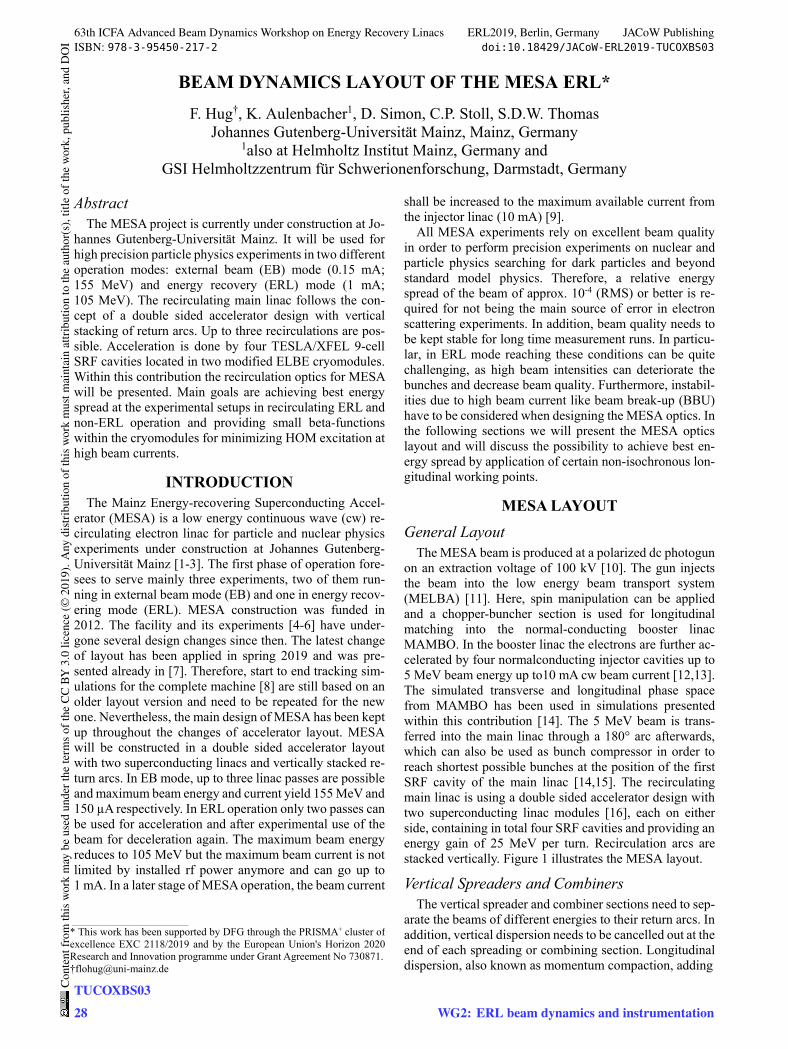
on an extraction voltage of 100 kV [10]. The gun injects the beam into the low energy beam transport system (MELBA) [11]. Here, spin manipulation can be applied and a chopper-buncher section is used for longitudinal matching into the normal-conducting booster linac MAMBO. In the booster linac the electrons are further ac-celerated by four normalconducting injector cavities up to 5 MeV beam energy up to10 mA cw beam current [12,13]. The simulated transverse and longitudinal phase space from MAMBO has been used in simulations presented within this contribution [14]. The 5 MeV beam is trans-ferred into the main linac through a 180° arc afterwards, which can also be used as bunch compressor in order to reach shortest possible bunches at the position of the first SRF cavity of the main linac [14,15]. The recirculating main linac is using a double sided accelerator design with two superconducting linac modules [16], each on either side, containing in total four SRF cavities and providing an energy gain of 25 MeV per turn. Recirculation arcs are stacked vertically. Figure 1 illustrates the MESA layout.
Vertical Spreaders and Combiners The vertical spreader and combiner sections need to sep-
arate the beams of different energies to their return arcs. In addition, vertical dispersion needs to be cancelled out at the end of each spreading or combining section. Longitudinal dispersion, also known as momentum compaction, adding
___________________________________________
* This work has been supported by DFG through the PRISMA+ cluster of excellence EXC 2118/2019 and by the European Union's Horizon 2020Research and Innovation programme under Grant Agreement No 730871.†[email protected]
63th ICFA Advanced Beam Dynamics Workshop on Energy Recovery Linacs ERL2019, Berlin, Germany JACoW PublishingISBN: 978-3-95450-217-2 doi:10.18429/JACoW-ERL2019-TUCOXBS03
TUCOXBS0328
Cont
entf
rom
this
wor
km
aybe
used
unde
rthe
term
soft
heCC
BY3.
0lic
ence
(©20
19).
Any
distr
ibut
ion
ofth
isw
ork
mus
tmai
ntai
nat
tribu
tion
toth
eau
thor
(s),
title
ofth
ew
ork,
publ
isher
,and
DO
I
WG2: ERL beam dynamics and instrumentation
THE LHeC ERL – OPTICS AND PERFORMANCE OPTIMIZATION*
S.A. Bogacz†, Jefferson Lab, Newport News, VA, USA
Abstract Unprecedently high luminosity of 1034 cm-2s-1, promised
by the LHeC accelerator complex poses several beam dy-namics and lattice design challenges [1]. Here we present beam dynamics driven approach to accelerator design, which in particular, addresses emittance dilution due to quantum excitations and beam breakup instability in a large scale, multi-pass Energy Recovery Linac (ERL) [2]. The use of ERL accelerator technology to provide im-proved beam quality and higher brightness continues to be the subject of active community interest and active accel-erator development of future Electron Ion Colliders (EIC). Here, we employ current state of though for ERLs aiming at the energy frontier EIC. The main thrust of these studies was to enhance the collider performance, while limiting overall power consumption through exploring interplay be-tween emittance preservation and efficiencies promised by the ERL technology [3].
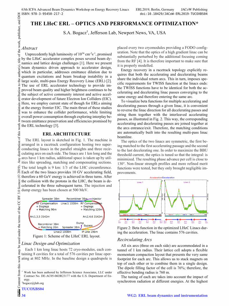
ERL ARCHITECTURE The ERL layout is sketched in Fig. 1. The machine is
arranged in a racetrack configuration hosting two super-conducting linacs in the parallel straights and three recir-culating arcs on each side. The linacs are 1 km long and the arcs have 1 km radius, additional space is taken up by util-ities like spreading, matching and compensating sections. The total length is 9 km: 1/3 of the LHC circumference. Each of the two linacs provides 10 GV accelerating field, therefore a 60 GeV energy is achieved in three turns. After the collision with the protons in the LHC, the beam is de-celerated in the three subsequent turns. The injection and dump energy has been chosen at 500 MeV.
Figure 1: Scheme of the LHeC ERL layout.
Linac Design and Optimization Each 1 km long linac hosts 72 cryo-modules, each con-
taining 8 cavities for a total of 576 cavities per linac oper-ating at 802 MHz. In the baseline design a quadrupole is
placed every two cryomodules providing a FODO config-uration. Note that the optics of a high gradient linac can be substantially perturbed by the additional focusing coming from the RF [4]. It is therefore important to make sure that it is properly modelled.
Energy recovery in a racetrack topology explicitly re-quires that both the accelerating and decelerating beams share the individual return arcs. This in turn, imposes spe-cific requirements for TWISS function at the linacs ends: the TWISS functions have to be identical for both the ac-celerating and decelerating linac passes converging to the same energy and therefore entering the same arc.
To visualize beta functions for multiple accelerating and decelerating passes through a given linac, it is convenient to reverse the linac direction for all decelerating passes and string them together with the interleaved accelerating passes, as illustrated in Fig. 2. This way, the corresponding accelerating and decelerating passes are joined together at the arcs entrance/exit. Therefore, the matching conditions are automatically built into the resulting multi-pass linac beamline.
The optics of the two linacs are symmetric, the first be-ing matched to the first accelerating passage and the second to the last decelerating one. In order to maximize the BBU threshold current, the optics is tuned so that the integral: is minimized. The resulting phase advance per cell is close to 130°. Non-linear strength profiles and more refined merit functions were tested, but they only brought negligible im-provements.
Figure 2: Beta function in the optimized LHeC Linacs dur-ing the acceleration. The linac contains 576 cavities.
Recirculating Arcs All six arcs (three on each side) are accommodated in a
tunnel of 1 km radius. Their lattice cell adopts a flexible momentum compaction layout that presents the very same footprint for each arc. This allows us to stack magnets on top of each other or to combine them in a single design. The dipole filling factor of the cell is 76%; therefore, the effective bending radius is 760 m.
The tuning of each arc takes into account the impact of synchrotron radiation at different energies. At the highest
___________________________________________
* Work has been authored by Jefferson Science Associates, LLC underContract No. DE-AC05-06OR23177 with the U.S. Department of En-ergy.
63th ICFA Advanced Beam Dynamics Workshop on Energy Recovery Linacs ERL2019, Berlin, Germany JACoW PublishingISBN: 978-3-95450-217-2 doi:10.18429/JACoW-ERL2019-TUCOXBS04
TUCOXBS0434
Cont
entf
rom
this
wor
km
aybe
used
unde
rthe
term
soft
heCC
BY3.
0lic
ence
(©20
19).
Any
distr
ibut
ion
ofth
isw
ork
mus
tmai
ntai
nat
tribu
tion
toth
eau
thor
(s),
title
ofth
ew
ork,
publ
isher
,and
DO
I
WG2: ERL beam dynamics and instrumentation
BEAM TIMING AND CAVITY PHASINGR. Koscica∗, N. Banerjee, G. H. Hoffstaetter, W. Lou, G. Premawardhana
Cornell University (CLASSE), Ithaca, NY 14853, USA
AbstractIn a multi-pass Energy Recovery Linac (ERL), each cav-
ity must regain all energy expended from beam accelerationduring beam deceleration. The beam should also achievespecific energy targets during each loop that returns it tothe linac. To satisfy the energy recovery and loop require-ments, one must specify the phase and voltage of cavityfields, and one must control the beam flight times throughthe return loops. Adequate values for these parameters canbe found by using a full scale numerical optimization pro-gram. If symmetry is imposed in beam time and energyduring acceleration and deceleration, the number of parame-ters needed decreases, simplifying the optimization. As anexample, symmetric models of the Cornell BNL ERL TestAccelerator (CBETA) are considered. Energy recovery re-sults from recent CBETA single-turn tests are presented, aswell as multi-turn solutions that satisfy CBETA optimizationtargets of loop energy and zero cavity loading.
INTRODUCTIONThe Energy Recovery Linac (ERL) is designed to cre-
ate high-quality, high-current beams at a lower energy costthan conventional linacs. Energy transferred to the beamduring acceleration is later recovered by the system. In anERL where the beam accelerates and decelerates throughthe same linac, full energy recovery is achieved when eachradio-frequency (RF) cavity in the linac recovers the energythat it originally expended: a beam ideally causes zero netpower load on the system. In multiturn ERLs, the beamenters the linac at different speeds during each acceleratingor decelerating pass. As a result, the beam may experiencephases slipped away from the ultrarelativistic case, and thisphase slippage can result in incomplete energy recovery.
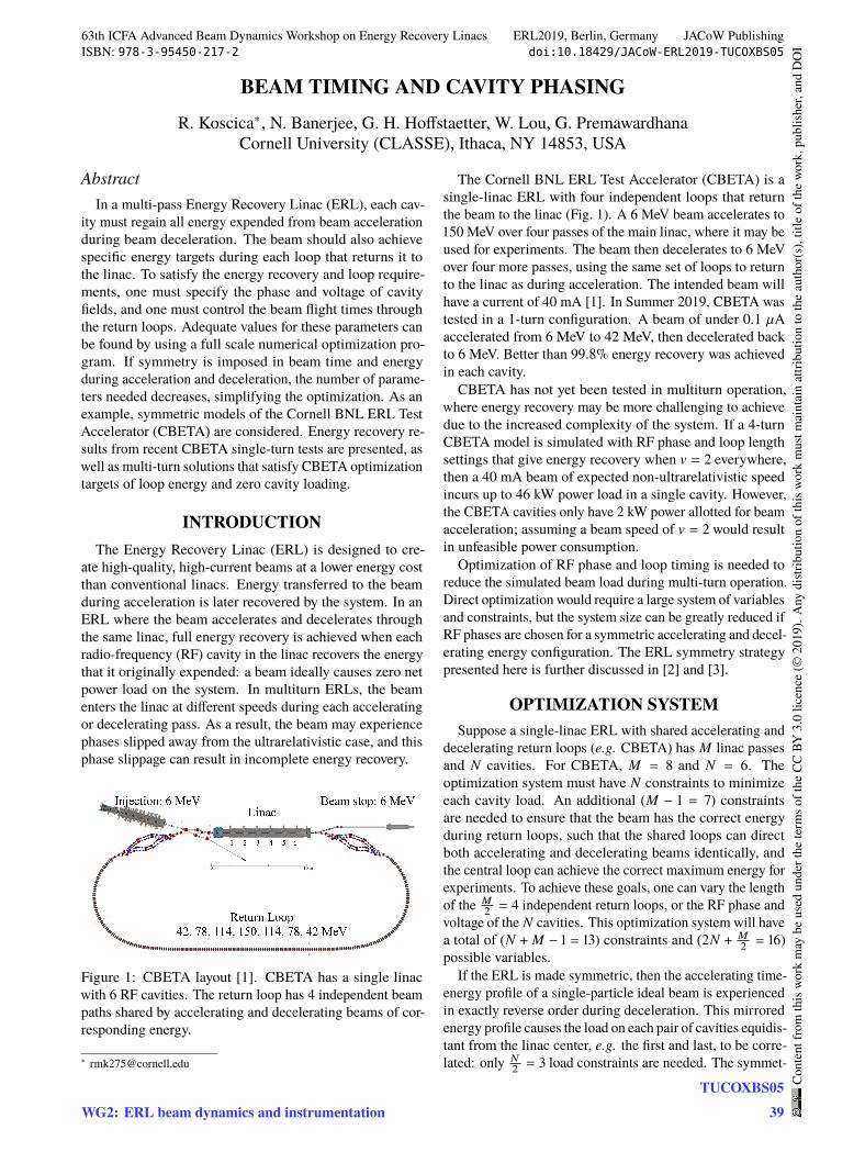
Figure 1: CBETA layout [1]. CBETA has a single linacwith 6 RF cavities. The return loop has 4 independent beampaths shared by accelerating and decelerating beams of cor-responding energy.
The Cornell BNL ERL Test Accelerator (CBETA) is asingle-linac ERL with four independent loops that returnthe beam to the linac (Fig. 1). A 6 MeV beam accelerates to150 MeV over four passes of the main linac, where it may beused for experiments. The beam then decelerates to 6 MeVover four more passes, using the same set of loops to returnto the linac as during acceleration. The intended beam willhave a current of 40 mA [1]. In Summer 2019, CBETA wastested in a 1-turn configuration. A beam of under 0.1 `Aaccelerated from 6 MeV to 42 MeV, then decelerated backto 6 MeV. Better than 99.8% energy recovery was achievedin each cavity.
CBETA has not yet been tested in multiturn operation,where energy recovery may be more challenging to achievedue to the increased complexity of the system. If a 4-turnCBETA model is simulated with RF phase and loop lengthsettings that give energy recovery when 𝑣 = 𝑐 everywhere,then a 40 mA beam of expected non-ultrarelativistic speedincurs up to 46 kW power load in a single cavity. However,the CBETA cavities only have 2 kW power allotted for beamacceleration; assuming a beam speed of 𝑣 = 𝑐 would resultin unfeasible power consumption.
Optimization of RF phase and loop timing is needed toreduce the simulated beam load during multi-turn operation.Direct optimization would require a large system of variablesand constraints, but the system size can be greatly reduced ifRF phases are chosen for a symmetric accelerating and decel-erating energy configuration. The ERL symmetry strategypresented here is further discussed in [2] and [3].
OPTIMIZATION SYSTEMSuppose a single-linac ERL with shared accelerating and
decelerating return loops (e.g. CBETA) has 𝑀 linac passesand 𝑁 cavities. For CBETA, 𝑀 = 8 and 𝑁 = 6. Theoptimization system must have 𝑁 constraints to minimizeeach cavity load. An additional (𝑀 − 1 = 7) constraintsare needed to ensure that the beam has the correct energyduring return loops, such that the shared loops can directboth accelerating and decelerating beams identically, andthe central loop can achieve the correct maximum energy forexperiments. To achieve these goals, one can vary the lengthof the 𝑀
2= 4 independent return loops, or the RF phase and
voltage of the 𝑁 cavities. This optimization system will havea total of (𝑁 + 𝑀 − 1 = 13) constraints and (2𝑁 + 𝑀
2= 16)
possible variables.If the ERL is made symmetric, then the accelerating time-
energy profile of a single-particle ideal beam is experiencedin exactly reverse order during deceleration. This mirroredenergy profile causes the load on each pair of cavities equidis-tant from the linac center, e.g. the first and last, to be corre-lated: only 𝑁
2= 3 load constraints are needed. The symmet-
63th ICFA Advanced Beam Dynamics Workshop on Energy Recovery Linacs ERL2019, Berlin, Germany JACoW PublishingISBN: 978-3-95450-217-2 doi:10.18429/JACoW-ERL2019-TUCOXBS05
WG2: ERL beam dynamics and instrumentationTUCOXBS05
39
Cont
entf
rom
this
wor
km
aybe
used
unde
rthe
term
soft
heCC
BY3.
0lic
ence
(©20
19).
Any
distr
ibut
ion
ofth
isw
ork
mus
tmai
ntai
nat
tribu
tion
toth
eau
thor
(s),
title
ofth
ew
ork,
publ
isher
,and
DO
I
A FERROELECTRIC FAST REACTIVE TUNER (FE-FRT) TO COMBATMICROPHONICS∗
N. Shipman, J. Bastard, M. Coly, F. Gerigk, A. Macpherson, N. Stapley,CERN, Geneva, Switzerland
I. Ben-Zvi, Brookhaven National Laboratory, Upton NY, USAC. Jing, A. Kanareykin, Euclid Techlabs LLC, Gaithersburg MD, USA
G. Burt, A. Castilla, Lancaster University, Lancaster, UKE. Nenasheva, Ceramics Ltd, St.Petersburg, Russia
AbstractFerroElectric Fast Reactive Tuners (FE-FRTs) are a novel
type of tuner that may be able to achieve near perfect compen-sation of microphonics in the near future. This would elim-inate the need to design over-coupled fundamental powercouplers and thus significantly reduce RF power, particularlyfor low beam current applications.
The recently tested proof of principle FE-FRT is discussedand the theory and practice of FE-FRT operation are devel-oped. These theoretical methods are then used to explorethe potential benefits of using an FE-FRT with specific ERLproposals, which are seen as one of the major use cases.Specifically the ERLs considered are: eRHIC ERL, PERLE,LHeC ERL and the Cornell Light Source. Particular atten-tion is given to the substantial peak and average RF powerreductions which could be achieved; in many cases these areshown to be approximately an order of magnitude.
INTRODUCTIONEnergy Recovery Linacs (ERLs) are designed to operate
with virtually no beam loading. In principle, the only for-ward power that must be supplied to an ERL cavity is thatneeded to replace the power lost on the cavity walls. Forsuper conducting cavities this is rather small.
Unfortunately, even with well designed cryomodules, fre-quency excursions caused by microphonics are typicallyorders of magnitude larger than the natural bandwidth ofthe cavity and as a result almost all of the supplied forwardpower is reflected and lost.
Significant effort has been made in recent years to designfast mechanical piezo-electric tuners to combat microphon-ics. Whilst important progress has been made in this direc-tion[1–3], it is an extremely difficult challenge. Althoughpiezo-electric crystals are intrinsically fast, the speed of apiezo-electric tuner is limited by how fast a deformationcan be applied to the cavity wall. A cavity also has its ownmechanical resonances which imply complicated transferfunctions between piezo actuator input and cavity resonantfrequency. In addition, any applied mechanical deforma-tion will invariably excite additional unwanted mechanicalvibrations which will themselves affect the frequency.
Recent progress in ferroelectric (FE) material proper-ties[4–6] have now made an entirely new method of combat-∗ This work was supported in part by the DOE SBIR grant: DE-SC0007630.
ting microphonics viable. An FE-FRT is a device containingFE material which is coupled to the cavity via an antennaand transmission line. By applying a voltage to the FE, itspermittivity and therefore the reactance coupled to the cavityis altered, which changes the cavity’s resonant frequency.
FE-FRTs have no moving parts, do not act on the cavitymechanically and do not excite unwanted mechanical vibra-tions. They also operate outside of cryomodules avoidingthe cryogenic cost of dissipating power in liquid helium.
For ERLs and low beam loading machines FE-FRTs couldsoon offer significant power and cost savings.
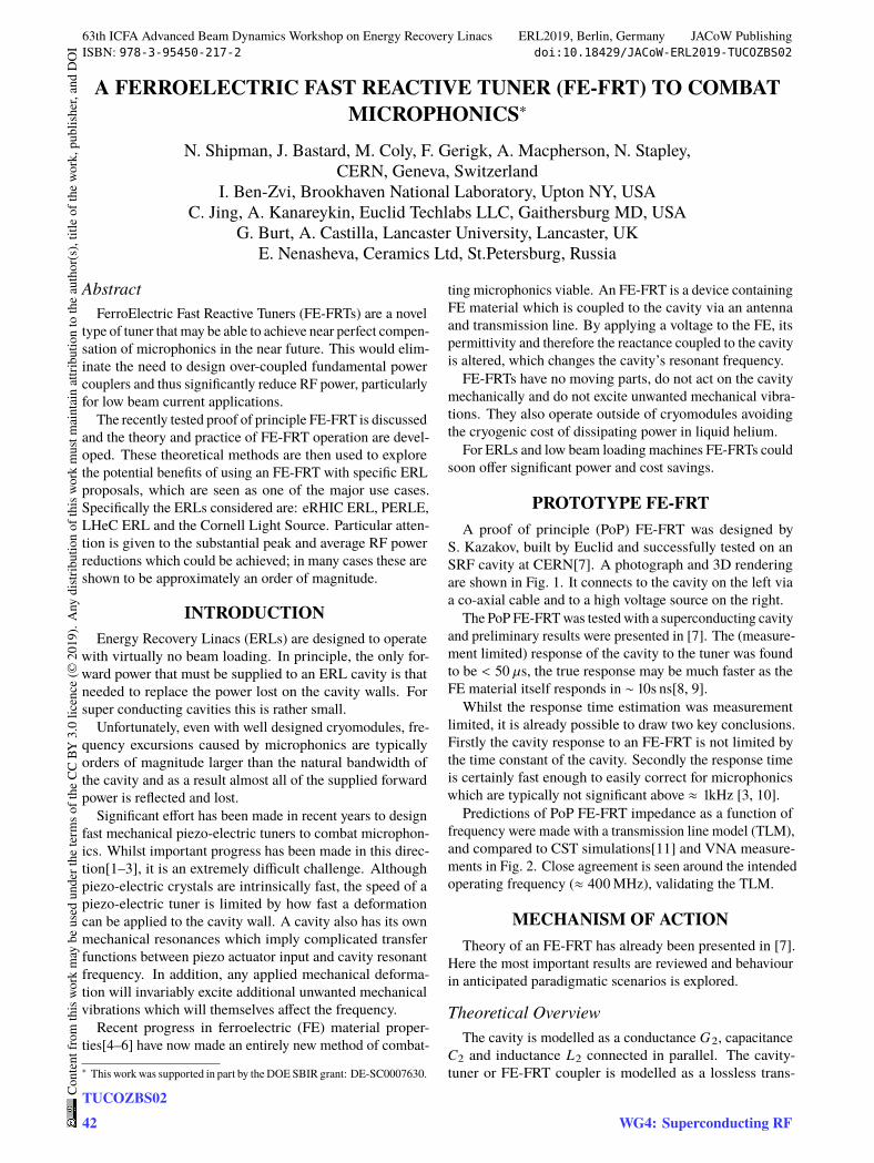
PROTOTYPE FE-FRTA proof of principle (PoP) FE-FRT was designed by
S. Kazakov, built by Euclid and successfully tested on anSRF cavity at CERN[7]. A photograph and 3D renderingare shown in Fig. 1. It connects to the cavity on the left viaa co-axial cable and to a high voltage source on the right.
The PoP FE-FRT was tested with a superconducting cavityand preliminary results were presented in [7]. The (measure-ment limited) response of the cavity to the tuner was foundto be < 50 `s, the true response may be much faster as theFE material itself responds in ∼ 10s ns[8, 9].
Whilst the response time estimation was measurementlimited, it is already possible to draw two key conclusions.Firstly the cavity response to an FE-FRT is not limited bythe time constant of the cavity. Secondly the response timeis certainly fast enough to easily correct for microphonicswhich are typically not significant above ≈ 1kHz [3, 10].
Predictions of PoP FE-FRT impedance as a function offrequency were made with a transmission line model (TLM),and compared to CST simulations[11] and VNA measure-ments in Fig. 2. Close agreement is seen around the intendedoperating frequency (≈ 400MHz), validating the TLM.
MECHANISM OF ACTIONTheory of an FE-FRT has already been presented in [7].
Here the most important results are reviewed and behaviourin anticipated paradigmatic scenarios is explored.
Theoretical OverviewThe cavity is modelled as a conductance 𝐺𝑐 , capacitance
𝐶𝑐 and inductance 𝐿𝑐 connected in parallel. The cavity-tuner or FE-FRT coupler is modelled as a lossless trans-
63th ICFA Advanced Beam Dynamics Workshop on Energy Recovery Linacs ERL2019, Berlin, Germany JACoW PublishingISBN: 978-3-95450-217-2 doi:10.18429/JACoW-ERL2019-TUCOZBS02
TUCOZBS0242
Cont
entf
rom
this
wor
km
aybe
used
unde
rthe
term
soft
heCC
BY3.
0lic
ence
(©20
19).
Any
distr
ibut
ion
ofth
isw
ork
mus
tmai
ntai
nat
tribu
tion
toth
eau
thor
(s),
title
ofth
ew
ork,
publ
isher
,and
DO
I
WG4: Superconducting RF
CHARACTERIZATION OF MICROPHONICS IN THE cERL MAIN LINAC SUPERCONDUCTING CAVITIES
F. Qiu1,2,†, S. Michizono1,2, T. Miura1,2, T. Matsumoto1,2, D. Arakawa1, H. Katagiri1, E. Kako1,2, H. Sakai1,2, K. Umemori1,2, T. Konomi1,2, M. Egi1,2
1High Energy Accelerator Research Organization (KEK), Tsukuba, Ibaraki 305-0801, Japan 2The Graduate Univiersity for Advanced Studies (Sokendai), Hayama, Kanagawa 240-0193, Japan
Abstract In the main linac (ML) of the KEK-cERL, two
superconducting cavities with high loaded Q (QL ≈ 1×10⁷) are operated in continuous wave (CW) mode. It is important to control and suppress the microphonics detuning owing to the low bandwidth of the cavities. We evaluated the background microphonics detuning by the low level radio frequency system during the beam operation. Interestingly, a “field level dependence microphonics” phenomenon was observed on one of the cavities in the ML. Several frequency components were suddenly excited if the cavity field is above a threshold field (~3 MV/m). We found that this threshold field is probably related with the cavity quench limits despite the unclear inherent physical mechanism. Furthermore, in order to optimize the cavity resonance control system for better microphonics rejection, we have measured the mechanical transfer function between the fast piezo tuner and cavity detuning. Finally, we validated this model by comparing the model response with actual system response.
INTRODUCTION At KEK, a compact energy recovery linac (cERL) was
constructed to study the feasibility of the future 3 GeV ERL based light source in 2009 [1]. It is a 1.3 GHz superconducting (SC) facility that operated in continuous-wave (CW) mode. In the main linac (ML) of the cERL, two nine-cell cavities (ML1 and ML2) were installed for energy recovery [2]. These two cavities have a high loaded Q (QL) of about 1×10⁷, with the corresponding cavity half-bandwidth (ω0.5) of about 65 Hz. The lower bandwidth makes the cavity phase very sensitive to the microphonics detuning. A low level radio frequency (LLRF) system is usually required to reduce the microphonics effects.
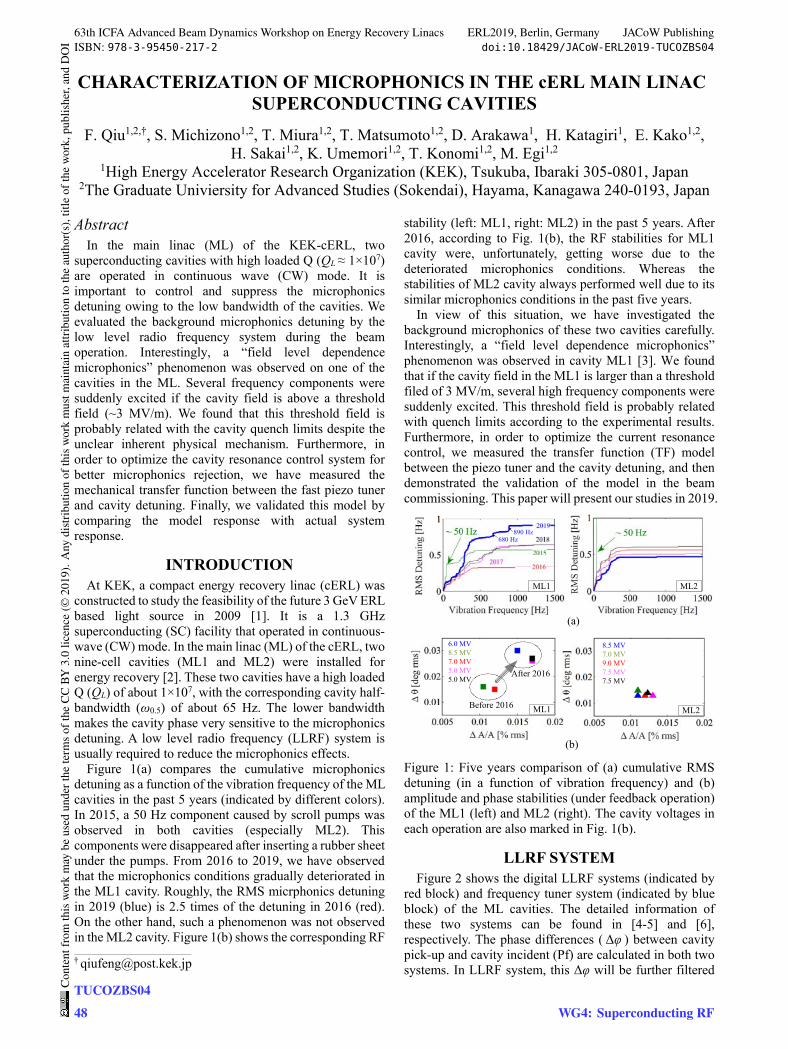
Figure 1(a) compares the cumulative microphonics detuning as a function of the vibration frequency of the ML cavities in the past 5 years (indicated by different colors). In 2015, a 50 Hz component caused by scroll pumps was observed in both cavities (especially ML2). This components were disappeared after inserting a rubber sheet under the pumps. From 2016 to 2019, we have observed that the microphonics conditions gradually deteriorated in the ML1 cavity. Roughly, the RMS micrphonics detuning in 2019 (blue) is 2.5 times of the detuning in 2016 (red). On the other hand, such a phenomenon was not observed in the ML2 cavity. Figure 1(b) shows the corresponding RF
stability (left: ML1, right: ML2) in the past 5 years. After 2016, according to Fig. 1(b), the RF stabilities for ML1 cavity were, unfortunately, getting worse due to the deteriorated microphonics conditions. Whereas the stabilities of ML2 cavity always performed well due to its similar microphonics conditions in the past five years.
In view of this situation, we have investigated the background microphonics of these two cavities carefully. Interestingly, a “field level dependence microphonics” phenomenon was observed in cavity ML1 [3]. We found that if the cavity field in the ML1 is larger than a threshold filed of 3 MV/m, several high frequency components were suddenly excited. This threshold field is probably related with quench limits according to the experimental results. Furthermore, in order to optimize the current resonance control, we measured the transfer function (TF) model between the piezo tuner and the cavity detuning, and then demonstrated the validation of the model in the beam commissioning. This paper will present our studies in 2019.
(a)
(b)
Before 2016
After 2016
ML1
ML1
ML2
ML2
890 Hz680 Hz
6.0 MV8.5 MV7.0 MV5.0 MV5.0 MV
8.5 MV7.0 MV9.0 MV7.5 MV7.5 MV
Figure 1: Five years comparison of (a) cumulative RMS detuning (in a function of vibration frequency) and (b) amplitude and phase stabilities (under feedback operation) of the ML1 (left) and ML2 (right). The cavity voltages in each operation are also marked in Fig. 1(b).
LLRF SYSTEM Figure 2 shows the digital LLRF systems (indicated by
red block) and frequency tuner system (indicated by blue block) of the ML cavities. The detailed information of these two systems can be found in [4-5] and [6], respectively. The phase differences ( Δφ ) between cavity pick-up and cavity incident (Pf) are calculated in both two systems. In LLRF system, this Δφ will be further filtered
___________________________________________
63th ICFA Advanced Beam Dynamics Workshop on Energy Recovery Linacs ERL2019, Berlin, Germany JACoW PublishingISBN: 978-3-95450-217-2 doi:10.18429/JACoW-ERL2019-TUCOZBS04
TUCOZBS0448
Cont
entf
rom
this
wor
km
aybe
used
unde
rthe
term
soft
heCC
BY3.
0lic
ence
(©20
19).
Any
distr
ibut
ion
ofth
isw
ork
mus
tmai
ntai
nat
tribu
tion
toth
eau
thor
(s),
title
ofth
ew
ork,
publ
isher
,and
DO
I
WG4: Superconducting RF
LOW LEVEL RF ERL EXPERIENCE AT THE S-DALINAC∗
M. Steinhorst†, M. Arnold, T. Bahlo, R. Grewe, L. Juergensen, J. Pforr, N. Pietralla,
F. Schließmann, S. Weih
Institut für Kernphysik, TU Darmstadt, Darmstadt, Germany
Abstract
In 2011 the present digital low-level RF (LLRF) control
system was set into operation. The first successful one-turn
ERL operation was set up in August 2017. The RF con-
trol performance was investigated during this new possible
operation mode in comparison to other modes that were
conventional already before at the S-DALINAC.
The efficiency of the ERL operation can be determined by
measurement of the beam loading in the cavities. This could
only be done for the first main accelerator cavity. Therefor,
an alternative way to determine the ERL efficiency from the
already done RF control stability measurements was done
to have a good estimate for this measurement. To quantify
the ERL efficiency via beam loading measurement an RF
power measurement system was developed which is able to
measure the RF powers and hence the beam loading for all
cavities simultaneously.
RF STABILITY
Introduction
The recirculating superconducting Darmstadt linear ac-
celerator S-DALINAC [1] is one of the main research instru-
ments at the institute for nuclear physics at the TU Darmstadt.
It is operating in cw mode at beam currents of up to 20 µA
with energies of up to 130 MeV using a thrice recirculating
scheme. The current in-house digital LLRF control system
of the S-DALINAC was developed in 2011 [2]. Since 2017
the S-DALINAC can be used as an energy recovery linac
(ERL). The ERL mode is adjusted by shifting the phase of
the beam by 180° in the second recirculation beam line. A
first succesful ERL operation was conducted in August 2017
with an injector energy of 2.5 MeV [3, 4]. To state if the
current digital LLRF control system is sufficient for a stable
ERL operation, it have to be tested in this operation mode
and the results have to be compared with stabilities in other
modes that are conventional at the S-DALINAC.
Measurement
The investigation of the stability of the current RF con-
trol system was done by measuring the residual amplitude
and phase errors of all cavities in four different operation
modes at a beam current of about 1 µA during an about two
hours measurement run. Figure 1 shows an overview of the
different operation modes. For RF stability investigation
the amplitude error and phase error data of the RF signal
was measured in the time domain using the RF control elec-
tronics [2, 5]. The data was then Fourier-transformed to the
∗ Supported by DFG (GRK 2128)† [email protected]
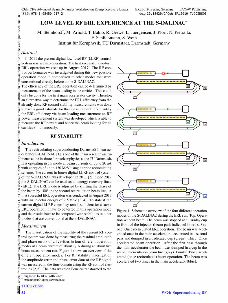
Figure 1: Schematic overview of the four different operation
modes of the S-DALINAC during the ERL run. Top: Opera-
tion without beam. The beam was stopped at a Faraday cup
in front of the injector (beam path indicated in red). Sec-
ond: Once recirculated ERL operation. The beam was accel-
erated once in the main accelerator, decelerated in a second
pass and dumped in a dedicated cup (green). Third: Once
accelerated beam operation. After the first pass through
the main accelerator the beam was dumped in a cup in the
second recirculation beam line (grey). Fourth: Twice accel-
erated (once recirculated) beam operation. The beam was
accelerated two times in the main accelerator (blue).
63th ICFA Advanced Beam Dynamics Workshop on Energy Recovery Linacs ERL2019, Berlin, Germany JACoW PublishingISBN: 978-3-95450-217-2 doi:10.18429/JACoW-ERL2019-TUCOZBS05
TUCOZBS0552
Cont
entf
rom
this
wor
km
aybe
used
unde
rthe
term
soft
heCC
BY3.
0lic
ence
(©20
19).
Any
distr
ibut
ion
ofth
isw
ork
mus
tmai
ntai
nat
tribu
tion
toth
eau
thor
(s),
title
ofth
ew
ork,
publ
isher
,and
DO
I
WG4: Superconducting RF
CRYOMODULES FOR THE MAINZ ENERGY-RECOVERING SUPERCONDUCTING ACCELERATOR (MESA)*
T. Stengler†, K. Aulenbacher1, F. Hug, D. Simon, C.P. Stoll, S.D.W. Thomas Johannes Gutenberg-Universität Mainz, Mainz, Germany
1also at Helmholtz Institut Mainz, Germany and GSI Helmholtzzentrum für Schwerionenforschung, Darmstadt, Germany
Abstract Two superconducting radio frequency acceleration cry-
omodules for the new multiturn ERL facility MESA (Mainz Energy Recovering Superconducting Accelerator) at Johannes Gutenberg-Universität Mainz have been fabri-cated by industry and are undergoing rf tests at the Helm-holtz Institut Mainz (HIM) currently. The modules for MESA are modified versions of the ELBE modules at Helmholtz Center Dresden-Rossendorf. The design energy gain per module and turn is set to 25 MeV. Acceleration is done by in total four TESLA/XFEL cavities, which have been vertically tested at DESY, Hamburg, Germany before being integrated in the MESA modules. In order to validate the performance of the fully dressed cryomodules a test stand has been set up at HIM. Within this contribution we report on the necessary modifications of the modules for high current ERL operation as well as on vertical and horizontal rf test results.
INTRODUCTION For the main linac of the Mainz Energy-Recovering Su-
perconducting Accelerator MESA [1-3], currently under construction at Johannes Gutenberg Universtität Mainz, two ELBE/Rossendorf-type [4] cryomodules have been produced by industry in Germany [5]. Each module con-sists of two TESLA/XFEL cavities running on an operation frequency of 1.3 GHz in continuous wave (cw) mode. For electron acceleration a gradient of 12.5 MV/m in each cav-ity is required to suit the experimental needs of the MESA facility. The dynamic losses of the cavities are limited due to the maximum available cooling power of the cryo-plant. Therefore, the unloaded quality factor of each cavity run-ning on the operating gradient of 12.5 MV/m needs to ex-ceed a value of 1010 at the operating temperature of 1.8 K. If MESA is run in ERL mode, a beam current of up to 1 mA needs to be accelerated and decelerated two turns each, yielding to a total sum of 4 mA electron beam in cw inside the accelerating cavities. To suit these needs of MESA, modifications on the module needed to be applied. In par-ticular, the cooling of the HOM antennas was optimized and a fast eigenfrequency tuner (XFEL/Saclay type) based on Piezo actuators for an optimized microphonics compen-sation has been integrated [6,7].
MESA CAVITIES
Specifications The performance goals for the MESA cavities and cry-
omodules have been specified beforehand and the vendor guaranteed parameters for the total energy gain per cry-omodule and the static and dynamic cryogenic losses. Ta-ble 1 gives an overview on the target values to be verified in the horizontal acceptance tests at HIM.
Table 1: Specifications of fully dressed cryomodule perfor-mance in horizontal test operated at 2 K [8]
Variable Specified Value
Energy Gain 25 MeV
Static Losses < 15 W
Dynamic Losses @ 25 MeV (cw) ∝ Q0 @12.5 MV/m
< 25 W> 1.25∙1010
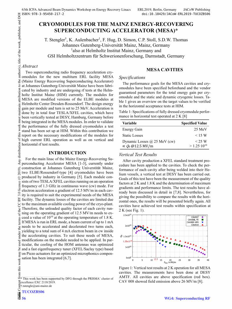
Vertical Test Results After cavity production a XFEL standard treatment pro-
cedure has been applied to the cavities. To check the per-formance of each cavity after being welded into their He-lium vessels, a vertical test at DESY has been carried out. Goals of this test have been the measurement of the quality factors at 2 K and 1.8 K and the determination of maximum gradients and performance limits. The test results have al-ready been discussed in detail in [7,8]. Nevertheless, for giving the possibility to compare the results with the hori-zontal ones, the results will be presented briefly again. All cavities have achieved test results within specification at 2 K (see Fig. 1).
Figure 1: Vertical test results at 2 K operation for all MESA cavities. The measurements have been done at DESY AMTF. All cavities are above specification (red box). CAV 008 showed field emission above 26 MV/m [8].
___________________________________________
* This work has been supported by DFG through the PRISMA+ cluster of excellence EXC 2118/2019. †[email protected]
63th ICFA Advanced Beam Dynamics Workshop on Energy Recovery Linacs ERL2019, Berlin, Germany JACoW PublishingISBN: 978-3-95450-217-2 doi:10.18429/JACoW-ERL2019-TUCOZBS06
TUCOZBS0656
Cont
entf
rom
this
wor
km
aybe
used
unde
rthe
term
soft
heCC
BY3.
0lic
ence
(©20
19).
Any
distr
ibut
ion
ofth
isw
ork
mus
tmai
ntai
nat
tribu
tion
toth
eau
thor
(s),
title
ofth
ew
ork,
publ
isher
,and
DO
I
WG4: Superconducting RF

High Current Performance of Alkali Antimonide Photocathode in LEReC DC Gun *
M. Gaowei†, E. Wang, J. Cen, A. Fedotov, D. Kayran, R. Lehn, C. J. Liaw, T. Rao, J. Tuozzolo, J. Walsh
Brookhaven National Laboratory, Upton, NY 11973, U.S.A
Abstract
The bi-alkali antimonide photocathode are chosen as the electron source material for the Low Energy RHIC electron Cooling (LEReC) project at RHIC, BNL based on its re-quirement for high bunch charge and long-time beam op-eration. This report presents the design and operation of the cathode deposition and transportation systems for the LEReC photocathodes, the cathode performance under the high current operation in the LEReC DC gun, as well as the characterization of the damaged cathodes from the long-time operation. In situ x-ray characterization results for the growth recipe of the alkali antimonide photocathodes pre-pared for the LEReC is also presented and discussed.
INTRODUCTION The bunched beam electron cooler (LEReC) at the Rel-
ativistic Heavy Ion Collider (RHIC) has been built to pro-vide luminosity improvement for Beam Energy Scan II (BES-II) physics program BES-II at RHIC. The photocath-ode DC gun in the LEReC accelerator is designed to pro-vide an average current of up to 100 mA, with a required quantum efficiency of 2% ~ 10% from the photocathode material. In the LEReC 2018 operation, the photocathode DC gun has generated an average current of 30 mA and operated non-stop for several hours, with cathode lifetime fitted to be ~ 100 hours. [1-4] In this paper we report the in situ x-ray characterization results for the growth recipe of the alkali antimonide photocathodes prepared for the LEReC operation. Cathode performance in the 9.3MHz CW operation of LEReC is also reported. Post operation characterization has been performed and results are dis-cussed in the last section of this paper.
CATHODE DEPOSITION The LEReC cathode deposition has been switched from
the effusion cell deposition back to the sequential 3 step deposition using SEAS getter sources since 2018. The dep-osition procedure we used for the bi-alkali antimonide pho-tocathode was well developed for the ERL and CeC pro-jects. [5] Compared to the CeC system, the LEReC depo-sition chamber differs slightly in geometry and does not have an active cooling capacity for the substrate. There-fore, the growth procedure in the LEReC deposition cham-ber has been optimized for this specific application. The detailed design of the LEReC deposition chamber was de-scribed in [6].
As was described in [6], the recipe we decided to use for the LEReC cathode is the well-established sequential growth recipe where 10 nm of Sb was deposited onto the substrate at 80 ˚C, followed by K and subsequent Cs depo-sition. The K step was performed at 135 ̊ C to 140 ̊ C, while the Cs step is performed between 130 ˚C to 70 ˚C, while the sample heater is turned off and the substrate cools down. Photocurrent generated by green light was moni-tored for both the K and the Cs step.
The temperature profile of the substrate with respect to the QE evolution through the K and the Cs step are plotted in Fig. 1. The inset photocurrent during the K step has been shown in × 5 scale for better display and the Cs QE was scaled by post QE calibration with a green laser with known power from the characterization chamber. For the LEReC cathode, we decided to seize the K deposition at an early stage, shortly after the QE rise and before its maxi-mum. The Cs growth is stopped after substrate temperature drops below 70 ˚C, which is the known temperature for maintaining the stable stoichiometry of K2CsSb. [7]
Figure 1: The temperature profile of the substrate with
respect to the QE evolution in the Cs step.
The full deposition process takes ~ 2 hrs, while the
whole deposition cycle for one cathode is typically 12 hrs, including the substrate heating cleaning, cathode cool down, QE mapping and puck exchange. The production rate for this deposition system is therefore 2 cathodes per day.
In 2018, we have produced 28 cathodes using this sys-tem. In 2019, the produced cathodes increased to 38, with an average deposition QE increased from 5.41% to 6.25%. Figure 2 and Table 1 listed all the as measured deposition QE from the LEReC cathodes in 2018 and 2019. The opti-mized deposition procedure for the LEReC deposition sys-tem has yielded ~ 1% higher average QE and an overall
___________________________________________
*This work was carried out at Brookhaven Science Associates, LLC under contract DE-SC0012704 with the U.S. DOE. † [email protected]
63th ICFA Advanced Beam Dynamics Workshop on Energy Recovery Linacs ERL2019, Berlin, Germany JACoW PublishingISBN: 978-3-95450-217-2 doi:10.18429/JACoW-ERL2019-WECOXBS02
WG3: Electron sources and injectorsWECOXBS02
61
Cont
entf
rom
this
wor
km
aybe
used
unde
rthe
term
soft
heCC
BY3.
0lic
ence
(©20
19).
Any
distr
ibut
ion
ofth
isw
ork
mus
tmai
ntai
nat
tribu
tion
toth
eau
thor
(s),
title
ofth
ew
ork,
publ
isher
,and
DO
I

BENCH TEST RESULTS OF CW 100 mA ELECTRON RF GUN FOR NOVOSIBIRSK ERL BASED FEL *
V. N. Volkov †, V. Arbuzov, E. Kenzhebulatov, E. Kolobanov, A. Kondakov, E. Kozyrev, S. Krutikhin, I. Kuptsov, G. Kurkin, S. Motygin, A. Murasev, V. Ovchar, V.M. Petrov, A. Pilan, V.
Repkov, M. Scheglov, I. Sedlyarov, S. Serednyakov, O. Shevchenko, S. Tararyshkin, A. Tribendis, N. Vinokurov, BINP SB RAS, Novosibirsk, Russia
Abstract Continuous wave (CW) 100 mA electron rf gun for
injecting the high-quality 300-400 keV electron beam in Novosibirsk Energy Recovery Linac (ERL) and driving Free Electron Laser (FEL) was developed, built, and commissioned at BINP SB RAS. The RF gun consists of normal conducting 90 MHz rf cavity with a gridded thermionic cathode unit. Bench tests of rf gun is confirmed good results in strict accordance with our numerical calculations. The gun was tested up to the design specifications at a test bench that includes a diagnostics beam line. The rf gun stand testing showed reliable work, unpretentious for vacuum conditions and stable in long-term operation. The design features of different components of the rf gun are presented. Preparation and commissioning experience is discussed. The latest bench test beam results are reported.
INTRODUCTION Recent projects of advanced sources of electromagnetic
radiation [1] are based on the new class of electron accelerators where the beam current is not limited by the power of rf system – energy recovery linacs (ERLs). Such accelerators require electron guns operating in continuous wave (cw) mode with high average current. The only solution is an rf gun, where the cathode is installed inside the rf cavity. There are no back bombardment ions in rf guns so there are no cathode degradation, and the vacuum condition does not critical there (see Table 1). The most powerful Novosibirsk FEL [2] can be more powerful by one order on magnitude with this rf gun [3-5].
RF GUN AND DIAGNOSTIC STAND The rf gun and diagnostic stand are presented in Fig. 1. The RF gun cavity is made on the base of standard
bimetallic cavity of Novosibirsk ERL. Detailed information can be found in [3-5]. Only the insert with the thermionic cathode-grid unit is built into the cavity. The gridded thermionic dispenser cathode is driven by special modulator with GaN rf transistor. The modulator generates a launch pulse voltage of up to 150 V and the duration of about 1 ns in any series with repetition frequencies of 0.01 - 90 MHz.
The insert focusing electrode has a concave form to decrease the electric RF field at the grid surface down to 1 MV/m (by one order on magnitude). Due to this the fields
before the grid and after it becomes equal to each other so the laminarity of the electron beam flow through the grid remains higher and beam emittance lower. Furthermore, the insert focusing electrode executes the strong rf focusing on the beam just near the cathode that ensures the beam emittance compensation at the relatively low electric field at the cathode. Also it ensures the absence of dark currents in the beam.
There are in the stand: 30 kW water cooled beam dump with 5 cm lead radiation shield, wideband Wall Current Monitor (WCM2) inserted into the replaceable target, Transition Radiation Sensor, the pair of standard WCM, three focusing solenoids, and the special testing cavity.
Table 1: Measured RF Gun Characteristics
Average beam current, mA ≤100 Cavity Frequency, MHz 90Bunch energy, keV 100 ÷ 400Bunch duration (FWHM), ns 0.06 ÷ 0.6Bunch emittance, mm mrad 10Bunch charge, nC 0.3 ÷ 1.12Repetition frequency, MHz 0.01 ÷ 90Radiation Doze Power, mR/h 100/2m Operating pressure, Torr 10-9…10-7 Cavity RF loses, kW 20
Figure 1: Rf gun and stand layout: 1-Power input coupler; 2- Cavity shell; 3-Cavity back wall; 4-Sliding tuner; 5-Insert; 6-Cathode injection/extraction channel; 7-Thermionic cathode-grid unit; 8-Concave focusing electrode; 9-Cone like nose; 10-Loop coupler; 11-Vacuum pumping port; A-Emittance compensation solenoid; B-First Wall Current Monitor (WCM); C, D -Solenoids ; E-Wideband WCM and transition radiation
___________________________________________
* Work supported by Russian Science Found- n (project N 14-50-00080) † [email protected]
63th ICFA Advanced Beam Dynamics Workshop on Energy Recovery Linacs ERL2019, Berlin, Germany JACoW PublishingISBN: 978-3-95450-217-2 doi:10.18429/JACoW-ERL2019-WECOXBS03
WG3: Electron sources and injectorsWECOXBS03
65
Cont
entf
rom
this
wor
km
aybe
used
unde
rthe
term
soft
heCC
BY3.
0lic
ence
(©20
19).
Any
distr
ibut
ion
ofth
isw
ork
mus
tmai
ntai
nat
tribu
tion
toth
eau
thor
(s),
title
ofth
ew
ork,
publ
isher
,and
DO
I

STATUS AND FUTURE PERSPECTIVE OF THE TRIUMF E-LINACS.D. Rädel∗, M. Alcorta, F. Ames, E. Chapman, K. Fong, B. Humphries, O. Kester, D. Kishi,
S.R. Koscielniak, R.E. Laxdal, Y.Y. Ma, T. Planche, M. Rowe, V.A. Verzilov,TRIUMF, Vancouver, Canada
Abstract
The currently installed configuration of TRIUMF’s super-conducting electron linac (e-linac) can produce an electronbeam up to 30 MeV and 10 mA. Low beam power commis-sioning of the e-linac spanning the section from the electrongun to the high energy dump took place in summer 2018 and2019 with an achieved beam energy of 30 MeV. As the driverof the Advanced Rare Isotope Laboratory (ARIEL1) project,the e-linac will deliver electrons to a photo-converter targetstation to produce neutron-rich rare isotope beams (RIB) viaphoto fission. The e-linac will have sufficient beam powerto support the demands of other user community as well.This driver accelerator could serve as a production machinefor high field THz radiation and as irradiation centre. Arecirculation of the beam would be beneficial for RIB pro-duction at higher beam energy and would allow for highbunch compression to generate THz radiation. Such a sys-tem would also allow for the investigation of a high beamintensity energy recovery linac. To this end, TRIUMF isinvestigating the design of an alternate circulation path andthe beam dynamics as a first step.
INTRODUCTION
TRIUMF’s e-linac is a driver accelerator establishedwithin the ARIEL project which was proposed in 2008 [1].The description of the scientific program can be found in[2, 3].
The layout of the e-linac is shown in Figure 1, includingDC gun, bunch compressor and third cryomodule EACB.Currently still in the commissioning phase, the e-linac isoperating in a continuous wave (cw) mode with 100 W beampower. This is limited by the present license for beam ener-gies above 10 MeV.
With its final beam specification of 30 MeV and 10 mAthe e-linac is an ideal test driver for a high power, highintensity THz photon source. Application for THz radiationare of high-field nonlinear spectroscopy, imaging (includingmicroscopy), biology and medicine as well as in industrialapplications.
The Canadian photon science community has a high de-mand and needs for light sources, therefore the e-linac is apotential drive for a high brilliance source for an IR-FEL. [4]
∗ [email protected] ARIEL is funded by the Canada Foundation for Innovation, the Provinces
AB, BC, MA, ON, QC, and TRIUMF. TRIUMF receives funding via acontribution agreement with the National Research Council of Canada.
COMMISSIONING UPDATEThis year TRIUMF continued commissioning the e-linac.
In 2018 the commissioning team achieved several milestoneswhile guiding the beam from the source to the main high en-ergy dump with a low power beam, see Figure 1. A detaileddescription of 2018 commissioning can be found in [5]. Also,during the commissioning the machine protection system(MPS) along the beamline has been commissioned step-by-step to the entrance of EACA.
Electron GunThe e-linac uses a 300 kV RF-modulated thermionic elec-
tron source. The source has been commissioned and operat-ing parameters have been verified. More detailed results canbe found in [6, 7]. The origin of recent high voltage prob-lems, which prevented operation above 270 kV, has beenidentified. They are caused by discharges along a high volt-age cable, which connects the power supply to the source.An improvement of the design is being implemented.
Machine Protection SystemThe e-linac beam loss monitors (BLM) of the MPS are
undergoing commissioning [8]. Currently the BLMs in thelow and medium energy sections of the e-linac (300 keV and10 MeV) have been commissioned with a combination ofBGO scintillator coupled to a Photo-Multiplier Tube andlong ionization chambers. The BLM commissioning inthe high-energy section (300 MeV) is underway. Once theBLMs have been commissioned, the power will be slowlyincreased above 100 W to test the various components of theaccelerator, including the 100 kW beam dump.
RFAfter passing an injection cryo module that boost the elec-
tron beam energy to 10 MeV, the main acceleration happensin the main superconducting acceleration module equippedwith two 1.3 GHz nine-cell radio frequency (rf) cavities.Both cavities are driven by one single klystron in a self-excited loop (SEL) in vector sum control [9]. During the2018 commissioning both cavities were locked and success-fully driven together. Instabilities seeded by microphonicsand sustained by ponderomotive effects (internal electro-magnetic pressure [5]) limited the beam acceleration to anenergy of up to 25 MeV with a beam energy stability outsidespecification.
This year environmental vibration and consequent micro-phonic effects were reduced at most frequencies by passivemeans. This was accomplished by adding damping mate-rials or modifying design of several systems including theLN2 cryogenic system and the interfaces to the rf waveguide
63th ICFA Advanced Beam Dynamics Workshop on Energy Recovery Linacs ERL2019, Berlin, Germany JACoW PublishingISBN: 978-3-95450-217-2 doi:10.18429/JACoW-ERL2019-WEPNEC01
WEPNEC0170
Cont
entf
rom
this
wor
km
aybe
used
unde
rthe
term
soft
heCC
BY3.
0lic
ence
(©20
19).
Any
distr
ibut
ion
ofth
isw
ork
mus
tmai
ntai
nat
tribu
tion
toth
eau
thor
(s),
title
ofth
ew
ork,
publ
isher
,and
DO
I
WG1: ERL facilities

DISPERSION MATCHING WITH SPACE CHARGE IN MESAA. Khan∗, O. Boine-Frankenheim, Technische Universität Darmstadt, Germany
K. Aulenbacher, Johannes Gutenberg-Universität Mainz, Germany
AbstractFor intense electron bunches traversing through bends, as
for example the recirculation arcs of an Energy-RecoveryLinac (ERL), dispersion matching with space charge of anarc into the subsequent radio-frequency (RF) structure is es-sential to maintain the beam quality. We show that beam en-velopes and dispersion along the bends and recirculation arcsof an ERL, including space charge forces, can be matched toadjust the beam to the parameters of the subsequent section.The present study is focused on a small-scale, double-sidedrecirculating linac Mainz Energy-recovering Superconduct-ing Accelerator (MESA). MESA is an under constructiontwo pass ERL at the Johannes Gutenberg-Universität Mainz,which should deliver a continuous wave (CW) beam at 105MeV for physics experiments with a pseudo-internal target.In this work, a coupled transverse-longitudinal beam ma-trix approach for matching with space charge in MESA isemployed.
INTRODUCTIONFor intense electron bunches at low to medium energy
traversing through bends, it is essential to understand thedetails of space-charge-induced effects to maintain beamquality throughout the ERL operation [1]. Particularly, cur-rent dependent dispersion matching of an arc into the subse-quent RF section has been found to be essential to preservethe beam quality. Dispersion matching with space chargehas been discussed mostly in the context of high intensitybeams in conventional synchrotrons [2]. For example, [3, 4]outlined the concept of two different dispersion functions,one for the beam center, which is not affected by spacecharge, and one for the off-center particles. Experiments re-lated to space charge and dispersion with low energy protonbeams were performed in the CERN PS Booster, matchingthe beam from the linac into the synchrotron. Although thespace charge was found to be relevant, it was sufficient to usethe zero-intensity dispersion for the matching of the beamcenter, in order to improve the injection efficiency [5]. In thiswork, we show that the space-charge-modified dispersionplays a key role for the adjustment of the 𝑅56 required forboth the isochronous and the non-isochronous recirculationmode of an ERL.
An important role of the recirculation arc in an ERL is toprovide path length adjustment options to set the accuraterequired RF phase of 0◦ to 180° for acceleration and deceler-ation. Transverse space charge modifies the dispersion func-tion along the arc and so the momentum compaction whichis the transport matrix element 𝑅56 for the individual parti-cles. In case the arc settings are chosen for zero-intensity,
one would end up with a dispersion and bunch length differ-ent from the design values at a subsequent RF structure [6].It is therefore necessary to understand the modification ofdispersion due to space charge along the arc in order to doproper matching into the next lattice section. Longitudinalspace charge also plays an important role, especially forshort bunches and small momentum deviations. Longitudi-nal space-charge-induced variations in the bunch length ormomentum deviation also affect the transverse space chargeforce by varying the local current density and the transversebeam size through the dispersion.
DISPERSION WITH SPACE CHARGEIn the presence of bending magnets, the horizontal dis-
placement 𝑥 of a particle from the reference particle is writ-ten as [6]
𝑥 (𝑠) = 𝑥𝛽 (𝑠) + 𝐷0 (𝑠) 𝛿, (1)
where 𝑥𝛽 is the betatron oscillation amplitude, 𝐷0 ≡ 𝐷0 (𝑠)is the dispersion function, and 𝛿 = Δ𝑝/𝑝0 is the fractionalmomentum deviation. The linear dispersion function with-out space charge 𝐷0 (𝑠) is the solution of the equation [2]:
𝐷′′
0 (𝑠) + ^𝑥 (𝑠)𝐷0 (𝑠) =1
𝜌(𝑠) , (2)
which gives the local sensitivity of the particle trajectory tothe fractional momentum deviation 𝛿, and the prime denotesderivative with respect to distance 𝑠 along the beamline. 𝜌is the bending radius and ^𝑥 is the linearized horizontalexternal focusing gradient.
With space charge, we can write:
𝑥sc (𝑠) = 𝑥sc,𝛽 (𝑠) + 𝐷𝛿, (3)
where 𝐷 ≡ 𝐷 (𝑠) is the dispersion function with spacecharge.Taking the average of Eq. (1) and Eq. (3) and subtractingthem over the symmetrical phase space distribution, suchthat ⟨𝑥𝛽⟩ = ⟨𝑥sc,𝛽⟩ = 0, we obtain (see also [4]):
⟨𝑥sc⟩ − ⟨𝑥⟩ = (𝐷 − 𝐷0)⟨𝛿⟩. (4)
For a beam with a momentum distribution centered at thedesign momentum the dispersion describing the positionof the beam centroid is space charge independent. Thisalso explains the experimental results obtained in the CERNPS Booster [5]. There the dispersion was measured andmatched by changing the beam momentum and recordingthe displacement of the beam center.
To observe the effect of space charge on the individualparticle dispersion, we have to compute the second momentsof the beam distribution. Using the assumption that the mo-mentum deviation is uncorrelated to the betatron oscillations,
63th ICFA Advanced Beam Dynamics Workshop on Energy Recovery Linacs ERL2019, Berlin, Germany JACoW PublishingISBN: 978-3-95450-217-2 doi:10.18429/JACoW-ERL2019-WEPNEC08
WEPNEC0874
Cont
entf
rom
this
wor
km
aybe
used
unde
rthe
term
soft
heCC
BY3.
0lic
ence
(©20
19).
Any
distr
ibut
ion
ofth
isw
ork
mus
tmai
ntai
nat
tribu
tion
toth
eau
thor
(s),
title
ofth
ew
ork,
publ
isher
,and
DO
I
WG2: ERL beam dynamics and instrumentation

INVESTIGATION ON THE ION CLEARING OF MULTI-PURPOSEELECTRODES OF BERLINPRO
G. Pöplau∗, Universität zu Lübeck, Lübeck, GermanyA. Meseck, HZB, Berlin, and Johannes Gutenberg-Universität, Mainz, Germany
AbstractHigh-brightness electron beams provided by modern ac-
celerators require several measures to preserve their highquality and to avoid instabilities. The mitigation of the im-pact of residual ions is one of these measures. It is particu-larly important if high bunch charges in combination withhigh repetition rates are aimed for. This is because ions canbe trapped in the strong negative electrical potential of theelectron beam causing emittance blow-up, increased beamhalo and longitudinal and transverse instabilities. One ion-clearing strategy is the installation of clearing electrodes. Ofparticular interest in this context is the performance of multi-purpose electrodes, which are designed such that they allowfor a simultaneous ion-clearing and beam-position moni-toring. Such electrodes will be installed in the bERLinProfacility. In this contribution, we present numerical stud-ies of the performance of multi-purpose clearing-electrodesplanned for bERLinPro, i.e. we investigate the behavior ofions generated by electron bunches while passing throughthe field of the electrodes. Hereby, several ion species andconfigurations of electrodes are considered.
INTRODUCTIONThe Energy Recovery Linac bERLinPro is currently being
set up at the Helmholtz-Zentrum Berlin. Based on super-conductive RF (SRF) technology, it aims to deliver highcurrent, low emittance cw beams, and to demonstrate energyrecovery at unprecedented parameters [1].In general, Energy Recovery Linacs place very high de-
mands on maintaining beam brightness and reducing beamlosses. Ions in vicinity of the electrons have a ruinous impacton the brightness and stability of the beam. This also appliesto bERLinPro. Hence counter measures such as clearingelectrodes and their performance is of highest importancefor the project. For bERLinPro multi-purpose electrodes,that enable simultaneous ion-clearing and beam positionmonitoring were developed and built at the HZB [2].They consist of four rectangular electrode-plates, which
can in principal be biased independently with a voltage upto 1000V resulting in different voltage-configurations. Thedifferent voltage-configurations naturally have different dis-tributions of the electric field. In this paper, we evaluate theperformance of the bERLinPro multi-purpose electrodes forfour different voltage-configurations. We relate the differ-ence in performance for different voltage-configurations tothe motion of the ions within the corresponding clearingfields.
Table 1: Nominal Parameters of bERLinPro.
bERLinPro Bunch
Nominal Beam Energy 50MeVNominal Beam Charge 𝑄 77 pCMaximum Repetition Rate 1.3GHz
Transv. RMS Bunch Size 𝜎𝑥,𝑦 300𝜇mBunch Length 𝜎𝑡 2 psVacuum Pressure 5 ⋅ 10−10mbar
SIMULATION SETUP AND SIMULATIONTOOLS
In this section a short introduction to the simulation setupand the simulation tools are provided. Since the appliedmodels and simulation tools coincide with those used forformer studies, more details can be found in [2, 3]. Thenominal parameters of bERLinPro that are relevant for thesimulations are summarized in Table 1.
The Multi-Purpose ElectrodeA description of the technical details of the bERLinPro
multi-purpose electrode was given in [2]. Here we onlyprovide the information relevant for the presented simulationstudies. Themulti-purpose electrodes are constructed of fourrectangular stripes (electrode-plates) with a size of 10mmx 38mm. These stripes are placed pairwise in parallel witha distance of 24.72mm along the elliptical beam pipe ofbERLinPro (70mm x 40mm).
Figure 1: The potential of the bERLinPro multi-purposeelectrode with a voltage of −1000V supplied to all fourelectrode-plates.
Figure 1 shows the potential of the electrodes with thetypical voltage-configuration, where a voltage of −1000V is
63th ICFA Advanced Beam Dynamics Workshop on Energy Recovery Linacs ERL2019, Berlin, Germany JACoW PublishingISBN: 978-3-95450-217-2 doi:10.18429/JACoW-ERL2019-WEPNEC10
WEPNEC1080
Cont
entf
rom
this
wor
km
aybe
used
unde
rthe
term
soft
heCC
BY3.
0lic
ence
(©20
19).
Any
distr
ibut
ion
ofth
isw
ork
mus
tmai
ntai
nat
tribu
tion
toth
eau
thor
(s),
title
ofth
ew
ork,
publ
isher
,and
DO
I
WG2: ERL beam dynamics and instrumentation
X-RAY ICS SOURCE BASED ON MODIFIED PUSH-PULL ERLS
I. Drebot∗, A. Bacci, A. Bosotti, F. Broggi, S. Cialdi, L. Faillace, D. Giannotti,
D. Giove, P. Michelato, L. Monaco, R. Paparella, F. Prelz, M. Rossetti Conti, A. R. Rossi, L. Serafini,
D. Sertore, M. Statera, V. Torri, INFN, Milano, Italy
V. Petrillo, Universitá degli Studi di Milano & INFN, Milano, Italy
G. Galzerano, E. Puppin, Politecnico di Milano, Milano, Italy
A. Esposito, A. Gallo, C. Vaccarezza, INFN/LNF, Frascati Roma, Italy
G. Mettivier, P. Russo, A. Sarno, Universitá di Napoli, Napoli, Italy
P. Cardarelli, M. Gambaccini, G. Paternó, A. Taibi, Universitá di Ferrare & INFN, Ferrara, Italy
Abstract
We present the conceptual designs of BriXS and BriXsinO
(a minimal test-bench demonstrator of proof of principle) for
a compact X-ray Source based on innovative push-pull ERLs.
BriXS, the first stage of the Marix project, is a Compton
X-ray source based on superconducting cavity technology
with energy recirculation and on a laser system in Fabry-
Pérot cavity at a repetition rate of 100 MHz, producing
20-180 keV radiation for medical applications. The energy
recovery scheme based on a modified folded push-pull CW-
SC twin Linac ensemble allows to sustain MW-class beam
power with almost just one hundred kW active power dissi-
pation/consumption.
INTRODUCTION
BriXS (Bright and compact X-ray Source) [1] is a twin
Compton X-ray source based on superconductive cavities
technology for the electron beam with energy recirculation
and on a laser system in Fabry-Pérot cavity at a repetition
rate of 100 MHz, producing 20-180 keV radiation.
It has been conceived as the first acceleration stage of the
X-ray FEL MariX [2,3]. MariX is an X-ray FEL based on the
innovative design of a two-pass two-way superconducting
linear electron accelerator, equipped with an arc compressor
to be operated in CW mode at 1 MHz.
The double Compton X-ray sources will operate at very
high repetition rate 100 MHz, with 200 pC electron bunches
that means very high average current 20 mA.
These Compton sources are designed to operate with an
electron energy range of 30-100 MeV, which for a 20 mA
of current means 2 MW. Such a high beam power cannot
be dumped without deceleration, and together with the CW
(Continuous Wave) regime, it justifies to foresee an ERL
(Energy Recovery Linac) machine, like in the CBETA ERL
projecct [4].
The focus on enabled applications by such an energy range
and brilliance is on medical oriented research/investigations,
mainly in the radio-diagnostics and radio-therapy fields [5,6],
exploiting the unique features of monochromatic X-rays, as
well as in micro-biological studies, and, within this main-
stream, material studies, crystallography and museology for
cultural heritage investigations. In this paper, the layout and
the typical parameters of the BriXS X-ray source will be
discussed.
MACHINE LAYOUT
The BriXS layout, shown in Figure 1, consists of two
symmetric beam lines, fed by two independent photoinjec-
tors, where two equal and coupled Energy Recovery Linacs
(ERL) accelerate the electron beams. Electron trains are
extracted from the photo-cathodes Inj1 and Inj2 at the left
side of in Figure 1. The two ERLs (named ERL1 and ERL2
in the Figure) accelerate and decelerate the electron trains
in an unconventional push-and-pull scheme. Bunches from
Guns and travelling right away in the Figure are acceler-
ated, those coming back from the interaction points (IPs) are
decelerated during the energy recovery phase and brought
simultaneously to a single beam-dump. Each Linac is there-
fore traversed by two counter-propagating trains of electron
beams, both gaining and yielding energy. This push-and-pull
coupled scheme permits to concurrently drive two Compton
X-ray sources with the same degrees of freedom, in terms of
energy and electron beam quality, as a Linac driven source,
with the advantage that the coupled ERLs scheme, fed by
two independent RF, systems is more stable. CW electron
Guns, capable to produce such an average beam current, are
not yet state of the art. Some of the most promising photo
cathode Guns [7] as the Cornell DC Gun [8] and the RF-CW
Apex Gun [9] have been therefore compared by simulations.
Considering the simulations results was chosen the APEX
one. Partial modifications of the beam lines to host addi-
tional Compton interaction points are under study. BriXs
should be considered as a single folded ERL running two
beams. This scheme is more compact than two independent
ERLs, with the necessity of less magnetic elements and,
therefore, a minor cost. An important advantage is that the
present scheme provides two knobs for adjusting the phases
at the entrance of the linacs in the recovery stage, thus cir-
cumventing the necessity of additional matching lines for
running one single ERL at different energies.
INJECTOR
Two twin injectors are present in BriXS. The injector lay-
out of the BriXS/MariX common acceleration beam-line,
as sketched in Figure 2, is composed of the following ac-
celerating and focusing elements: 1. The CW RF Gun; 2.
63th ICFA Advanced Beam Dynamics Workshop on Energy Recovery Linacs ERL2019, Berlin, Germany JACoW PublishingISBN: 978-3-95450-217-2 doi:10.18429/JACoW-ERL2019-WEPNEC11
WEPNEC1184
Cont
entf
rom
this
wor
km
aybe
used
unde
rthe
term
soft
heCC
BY3.
0lic
ence
(©20
19).
Any
distr
ibut
ion
ofth
isw
ork
mus
tmai
ntai
nat
tribu
tion
toth
eau
thor
(s),
title
ofth
ew
ork,
publ
isher
,and
DO
I
WG5: ERL applications
PRELIMINARY INVESTIGATIONS AND PRE-RESEARCH SCHEME OF HIGH AVERAGE CURRENT ELECTRON INJECTORS AT IMP
Q.T. Zhao†, Z.M. Zhang, J.C. Yang, H.W. Zhao Institute of modern physics, Chinese academy of sciences, Lanzhou, China
Abstract High average current electron injectors are desired by
high average beam power SRF linacs. With respect to the different linac applications, different beam qualities are required. Two kinds of the electron guns are planned for future projects at IMP, one is thermionic electron gun dedicated for high average current, and another one is photocathode gun for high average current and high beam quality or even with high polarization. Current status and development of the high average current electron sources are investigated and summarized. The thermionic gun studies are planned and the feasible types of guns for the future Electron ion collider of China (EicC) project are also proposed. The pre-research of these required electron injectors is schemed, which will be the start of high aver-age current and high-quality electron source development at Institute of modern physics (IMP), Chinese academy of sciences (CAS).
INTRODUCTION High repetition rate, high average current electron in-
jectors are required by many high average power super-conducting radio frequency (SRF) electron linacs. These high average power SRF linacs are dedicated for different applications, such as high average power free-electron lasers (FEL) [1], medical isotope production [2], industry application [3], electron ion collider (EIC) [4], electron cooling for high energy heavy ions [5] and so on. With respect to different applications mentioned above, the requirements of the beam quality are different. The final beam quality required in the interaction region can be traced back to the requirements on the electron bunches from the injector, the first stage of the SRF linac. The electron injector, beginning with a cathode, is the source of the electrons. The quality, bunch length, and timing of the electrons injected into the first linac cavities are criti-cal to determining the properties of the final high energy electron bunch.
Electron injectors can use several different types of cathodes to generate the electrons. One approach is to use a thermionic cathode, which can produce high average currents, but its shortage is hard to generate short bunch length and high repetition rate electron bunches, and the beam quality is mediate. Another approach is to use a photocathode, which is very popular and the promising method to produce high quality electron bunches and can be used for applications with high quality beam, such as FEL, EIC and electron cooling. However, the thermal
issues, short lifetime, and drive-laser average power re-quirements currently present limitations for high average current photocathode injectors. Another unique advantage of the photocathode injector is capable to generate the polarization electron beam which is required for EIC. The electron gun can be classified into three types by the gun cavities and field modes, high voltage DC type, normal conducting RF and SRF type [6]. Due to the critical ther-mal loads for the normal conducting RF gun, it is not efficient and suitable for high average current and high average power electron source. Another issue of its poor vacuum condition, the normal conducting RF gun is not suitable for polarization electron source. Therefore, here we mainly talk about the high voltage DC gun and SRF gun.
The SRF linac projects are planned in IMP, one is dedi-cated with high average power application for medical isotope production and others are planned for EicC pro-ject [7], which has two SRF linacs, one requires polarized electron injectors with high beam quality and high polari-zation rate and another one needs high repetition rate, high bunch charge, high beam quality electron injectors for e-cooling of the high energy heavy ions. Different electron injectors are scheduled for the above projects based on the properties of the different types of the elec-tron injectors. In this paper, we discussed the designed and required injectors’ parameters for different applica-tion and proposed the solution and study plans of the injectors.
RF MODULATED THERMIONIC CATH-ODE HIGH VOLTAGE ELECTRON GUN Due to the ability to generate high average current, long
lifetime, and good stability and reliability, the thermionic cathode gun is preferred for many high average powers with mediate beam quality applications, like IR-FEL [8] and medical isotope production [9]. Normally, the thermi-onic cathode high voltage gun generates the direct cur-rent, which should be manipulated to short bunch with chopper and buncher devices, in order to match the RF acceleration. This method is inefficient and costly. Anoth-er method is gated the thermionic cathode high voltage DC gun with RF voltage, the generated electron bunch repetition rate is same with the frequency of the RF volt-age, which is very convenient to generate the high repeti-tion rate electron bunches, as high as 1 GHz [10]. This kind of gun is also considered to be the possible electron source for energy recovery linacs (ERLs) [11], like ERL based IR-FEL, electron cooling [12].
___________________________________________
† Email address: [email protected]
63th ICFA Advanced Beam Dynamics Workshop on Energy Recovery Linacs ERL2019, Berlin, Germany JACoW PublishingISBN: 978-3-95450-217-2 doi:10.18429/JACoW-ERL2019-WEPNEC13
WEPNEC1390
Cont
entf
rom
this
wor
km
aybe
used
unde
rthe
term
soft
heCC
BY3.
0lic
ence
(©20
19).
Any
distr
ibut
ion
ofth
isw
ork
mus
tmai
ntai
nat
tribu
tion
toth
eau
thor
(s),
title
ofth
ew
ork,
publ
isher
,and
DO
I
WG3: Electron sources and injectors
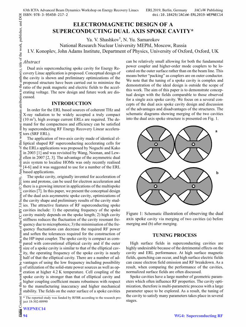
ELECTROMAGNETIC DESIGN OF A SUPERCONDUCTING DUAL AXIS SPOKE CAVITY*
Ya. V. Shashkov†, N. Yu. Samarokov National Research Nuclear University MEPhI, Moscow, Russia
I.V. Konoplev, John Adams Institute, Department of Physics, University of Oxford, Oxford, UK
Abstract Dual axis superconducting spoke cavity for Energy Re-
covery Linac application is proposed. Conceptual design of the cavity is shown and preliminary optimizations of the proposed structure have been carried out to minimize the ratio of the peak magnetic and electric fields to the accel-erating voltage. The new design and future work are dis-cussed.
INTRODUCTION In order for the ERL based sources of coherent THz and
X-ray radiation to be widely accepted a truly compact (10 m3), high average current ERLs are required. The de-mand for the compactness and efficiency can be satisfied by superconducting RF Energy Recovery Linear accelera-tors (SRF ERL).
The application of two-axis cavity made of identical el-liptical shaped RF superconducting accelerating cells for the ERLs applications was proposed by Noguchi and Kako in 2003 [1] and was revisited by Wang, Noonan, and Lew-ellen in 2007 [2, 3]. The advantage of the asymmetric dual axis system to localise HOMs was only recently realised [4-6] and it was suggested to use for a number of the ERL based applications.
The spoke cavity, originally invented for acceleration of ions and protons, can be used for electron acceleration and there is a growing interest in applications of the multispoke cavities [7]. In this paper, we present the conceptual design of the dual axis asymmetric spoke cavity, optimizations of the cavity shape and preliminary results of the cavity stud-ies. The attractive features of RF superconducting spoke cavities include: 1) the operating frequency of the spoke cavity mainly depends on the spoke length; 2) high cavity stiffness reduces the fluctuation of the cavity resonant fre-quency due to microphonics; 3) the minimisation of the fre-quency fluctuations can decrease the required RF power and soften the tolerances required for the construction of the HP input coupler. The spoke cavity is compact as com-pared with conventional elliptical cavity and if the outer size of a spoke cavity is similar to that of the elliptical cav-ity, the operating frequency of the spoke cavity is nearly half of that the elliptical cavity. There are a number of ad-vantages of using the low frequency including possibility of utilization of the solid-state power sources as well as op-eration at higher 4.2 K temperature. Cell coupling of the spoke cavity is stronger than that of elliptical cavity and higher coupling coefficient means robustness with respect to the manufacturing inaccuracy and higher mechanical stability. The fields on the outer surface of a spoke cavities
can be relatively small allowing for both the fundamental power coupler and higher-order mode couplers to be lo-cated on the outer surface rather than on the beam line. This means better “packing” as couplers are on outer conductor. We note that the tuning of a spoke cavity is complex and demonstration of the ideal design is outside the scope of this work. The aim of this paper is to demonstrate concep-tual design with the fields comparable to those observed for a single axis spoke cavity. We focus on a several con-cepts of the dual axis spoke cavity design and discussion of the advantages and disadvantages of the structures. The schematic diagrams showing merging of the two cavities into the dual axis spoke structure is presented on Fig. 1.
Figure 1: Schematic illustration of observing the dualaxis spoke cavity via merging of two cavities (a) beforemerging and (b) after merging.
TUNING PROCESS High surface fields in superconducting cavities are
highly undesirable because of the detrimental effects on the cavity and ERL performance. At high surface magnetic fields, quenching can occur, and high surface electric fields can cause electron field emission and RF breakdown. As a result, when comparing the performance of the cavities, normalized surface fields are often discussed.
Spoke cavities have a large number of geometric param-eters which often influence RF properties. The cavity opti-mization, therefore is multi-parametric process with a large parameter space to be explored. As a result, the tuning of the cavity to satisfy many parameters takes place in several stages.
____________________________________________
* The reported study was funded by RFBR according to the research pro-ject 18-302-00990
a
b
63th ICFA Advanced Beam Dynamics Workshop on Energy Recovery Linacs ERL2019, Berlin, Germany JACoW PublishingISBN: 978-3-95450-217-2 doi:10.18429/JACoW-ERL2019-WEPNEC14
WEPNEC1494
Cont
entf
rom
this
wor
km
aybe
used
unde
rthe
term
soft
heCC
BY3.
0lic
ence
(©20
19).
Any
distr
ibut
ion
ofth
isw
ork
mus
tmai
ntai
nat
tribu
tion
toth
eau
thor
(s),
title
ofth
ew
ork,
publ
isher
,and
DO
I
WG4: Superconducting RF
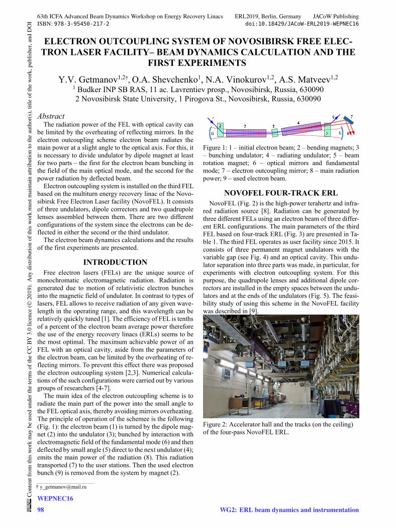
ELECTRON OUTCOUPLING SYSTEM OF NOVOSIBIRSK FREE ELEC-TRON LASER FACILITY– BEAM DYNAMICS CALCULATION AND THE
FIRST EXPERIMENTS
Y.V. Getmanov1,2†, O.A. Shevchenko1, N.A. Vinokurov1,2, A.S. Matveev1,2 1 Budker INP SB RAS, 11 ac. Lavrentiev prosp., Novosibirsk, Russia, 630090 2 Novosibirsk State University, 1 Pirogova St., Novosibirsk, Russia, 630090
Abstract The radiation power of the FEL with optical cavity can
be limited by the overheating of reflecting mirrors. In the electron outcoupling scheme electron beam radiates the main power at a slight angle to the optical axis. For this, it is necessary to divide undulator by dipole magnet at least for two parts – the first for the electron beam bunching in the field of the main optical mode, and the second for the power radiation by deflected beam.
Electron outcoupling system is installed on the third FEL based on the multiturn energy recovery linac of the Novo-sibirsk Free Electron Laser facility (NovoFEL). It consists of three undulators, dipole correctors and two quadrupole lenses assembled between them. There are two different configurations of the system since the electrons can be de-flected in either the second or the third undulator.
The electron beam dynamics calculations and the results of the first experiments are presented.
INTRODUCTION Free electron lasers (FELs) are the unique source of
monochromatic electromagnetic radiation. Radiation is generated due to motion of relativistic electron bunches into the magnetic field of undulator. In contrast to types of lasers, FEL allows to receive radiation of any given wave-length in the operating range, and this wavelength can be relatively quickly tuned [1]. The efficiency of FEL is tenths of a percent of the electron beam average power therefore the use of the energy recovery linacs (ERLs) seems to be the most optimal. The maximum achievable power of an FEL with an optical cavity, aside from the parameters of the electron beam, can be limited by the overheating of re-flecting mirrors. To prevent this effect there was proposed the electron outcoupling system [2,3]. Numerical calcula-tions of the such configurations were carried out by various groups of researchers [4-7].
The main idea of the electron outcoupling scheme is to radiate the main part of the power into the small angle to the FEL optical axis, thereby avoiding mirrors overheating. The principle of operation of the schemee is the following (Fig. 1): the electron beam (1) is turned by the dipole mag-net (2) into the undulator (3); bunched by interaction with electromagnetic field of the fundamental mode (6) and then deflected by small angle (5) direct to the next undulator (4); emits the main power of the radiation (8). This radiation transported (7) to the user stations. Then the used electron bunch (9) is removed from the system by magnet (2).
Figure 1: 1 – initial electron beam; 2 – bending magnets; 3 – bunching undulator; 4 – radiating undulator; 5 – beam rotation magnet; 6 – optical mirrors and fundamental mode; 7 – electron outcoupling mirror; 8 – main radiation power; 9 – used electron beam.
NOVOFEL FOUR-TRACK ERL NovoFEL (Fig. 2) is the high-power terahertz and infra-
red radiation source [8]. Radiation can be generated by three different FELs using an electron beam of three differ-ent ERL configurations. The main parameters of the third FEL based on four-track ERL (Fig. 3) are presented in Ta-ble 1. The third FEL operates as user facility since 2015. It consists of three permanent magnet undulators with the variable gap (see Fig. 4) and an optical cavity. This undu-lator separation into three parts was made, in particular, for experiments with electron outcoupling system. For this purpose, the quadrupole lenses and additional dipole cor-rectors are installed in the empty spaces between the undu-lators and at the ends of the undulators (Fig. 5). The feasi-bility study of using this scheme in the NovoFEL facility was described in [9].
Figure 2: Accelerator hall and the tracks (on the ceiling) of the four-pass NovoFEL ERL.
___________________________________________
63th ICFA Advanced Beam Dynamics Workshop on Energy Recovery Linacs ERL2019, Berlin, Germany JACoW PublishingISBN: 978-3-95450-217-2 doi:10.18429/JACoW-ERL2019-WEPNEC16
WEPNEC1698
Cont
entf
rom
this
wor
km
aybe
used
unde
rthe
term
soft
heCC
BY3.
0lic
ence
(©20
19).
Any
distr
ibut
ion
ofth
isw
ork
mus
tmai
ntai
nat
tribu
tion
toth
eau
thor
(s),
title
ofth
ew
ork,
publ
isher
,and
DO
I
WG2: ERL beam dynamics and instrumentation
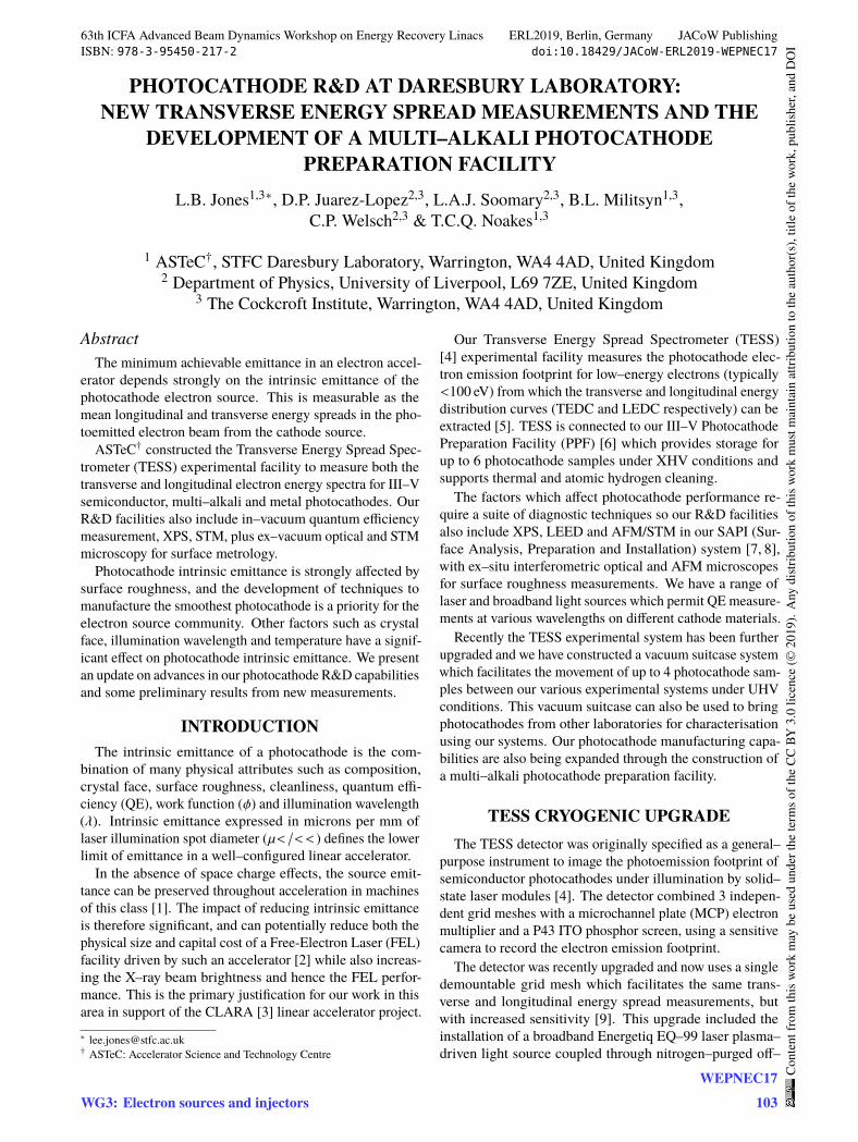
PHOTOCATHODE R&D AT DARESBURY LABORATORY:NEW TRANSVERSE ENERGY SPREAD MEASUREMENTS AND THE
DEVELOPMENT OF A MULTI–ALKALI PHOTOCATHODEPREPARATION FACILITY
L.B. Jones1,3∗, D.P. Juarez-Lopez2,3, L.A.J. Soomary2,3, B.L. Militsyn1,3,C.P. Welsch2,3 & T.C.Q. Noakes1,3
1 ASTeC†, STFC Daresbury Laboratory, Warrington, WA4 4AD, United Kingdom2 Department of Physics, University of Liverpool, L69 7ZE, United Kingdom
3 The Cockcroft Institute, Warrington, WA4 4AD, United Kingdom
AbstractThe minimum achievable emittance in an electron accel-
erator depends strongly on the intrinsic emittance of thephotocathode electron source. This is measurable as themean longitudinal and transverse energy spreads in the pho-toemitted electron beam from the cathode source.
ASTeC† constructed the Transverse Energy Spread Spec-trometer (TESS) experimental facility to measure both thetransverse and longitudinal electron energy spectra for III–Vsemiconductor, multi–alkali and metal photocathodes. OurR&D facilities also include in–vacuum quantum efficiencymeasurement, XPS, STM, plus ex–vacuum optical and STMmicroscopy for surface metrology.
Photocathode intrinsic emittance is strongly affected bysurface roughness, and the development of techniques tomanufacture the smoothest photocathode is a priority for theelectron source community. Other factors such as crystalface, illumination wavelength and temperature have a signif-icant effect on photocathode intrinsic emittance. We presentan update on advances in our photocathode R&D capabilitiesand some preliminary results from new measurements.
INTRODUCTIONThe intrinsic emittance of a photocathode is the com-
bination of many physical attributes such as composition,crystal face, surface roughness, cleanliness, quantum effi-ciency (QE), work function (𝜙) and illumination wavelength(_). Intrinsic emittance expressed in microns per mm oflaser illumination spot diameter (`𝑚/𝑚𝑚) defines the lowerlimit of emittance in a well–configured linear accelerator.
In the absence of space charge effects, the source emit-tance can be preserved throughout acceleration in machinesof this class [1]. The impact of reducing intrinsic emittanceis therefore significant, and can potentially reduce both thephysical size and capital cost of a Free-Electron Laser (FEL)facility driven by such an accelerator [2] while also increas-ing the X–ray beam brightness and hence the FEL perfor-mance. This is the primary justification for our work in thisarea in support of the CLARA [3] linear accelerator project.∗ [email protected]† ASTeC: Accelerator Science and Technology Centre
Our Transverse Energy Spread Spectrometer (TESS)[4] experimental facility measures the photocathode elec-tron emission footprint for low–energy electrons (typically<100 eV) from which the transverse and longitudinal energydistribution curves (TEDC and LEDC respectively) can beextracted [5]. TESS is connected to our III–V PhotocathodePreparation Facility (PPF) [6] which provides storage forup to 6 photocathode samples under XHV conditions andsupports thermal and atomic hydrogen cleaning.
The factors which affect photocathode performance re-quire a suite of diagnostic techniques so our R&D facilitiesalso include XPS, LEED and AFM/STM in our SAPI (Sur-face Analysis, Preparation and Installation) system [7, 8],with ex–situ interferometric optical and AFM microscopesfor surface roughness measurements. We have a range oflaser and broadband light sources which permit QE measure-ments at various wavelengths on different cathode materials.
Recently the TESS experimental system has been furtherupgraded and we have constructed a vacuum suitcase systemwhich facilitates the movement of up to 4 photocathode sam-ples between our various experimental systems under UHVconditions. This vacuum suitcase can also be used to bringphotocathodes from other laboratories for characterisationusing our systems. Our photocathode manufacturing capa-bilities are also being expanded through the construction ofa multi–alkali photocathode preparation facility.
TESS CRYOGENIC UPGRADEThe TESS detector was originally specified as a general–
purpose instrument to image the photoemission footprint ofsemiconductor photocathodes under illumination by solid–state laser modules [4]. The detector combined 3 indepen-dent grid meshes with a microchannel plate (MCP) electronmultiplier and a P43 ITO phosphor screen, using a sensitivecamera to record the electron emission footprint.
The detector was recently upgraded and now uses a singledemountable grid mesh which facilitates the same trans-verse and longitudinal energy spread measurements, butwith increased sensitivity [9]. This upgrade included theinstallation of a broadband Energetiq EQ–99 laser plasma–driven light source coupled through nitrogen–purged off–
63th ICFA Advanced Beam Dynamics Workshop on Energy Recovery Linacs ERL2019, Berlin, Germany JACoW PublishingISBN: 978-3-95450-217-2 doi:10.18429/JACoW-ERL2019-WEPNEC17
WG3: Electron sources and injectorsWEPNEC17
103
Cont
entf
rom
this
wor
km
aybe
used
unde
rthe
term
soft
heCC
BY3.
0lic
ence
(©20
19).
Any
distr
ibut
ion
ofth
isw
ork
mus
tmai
ntai
nat
tribu
tion
toth
eau
thor
(s),
title
ofth
ew
ork,
publ
isher
,and
DO
I
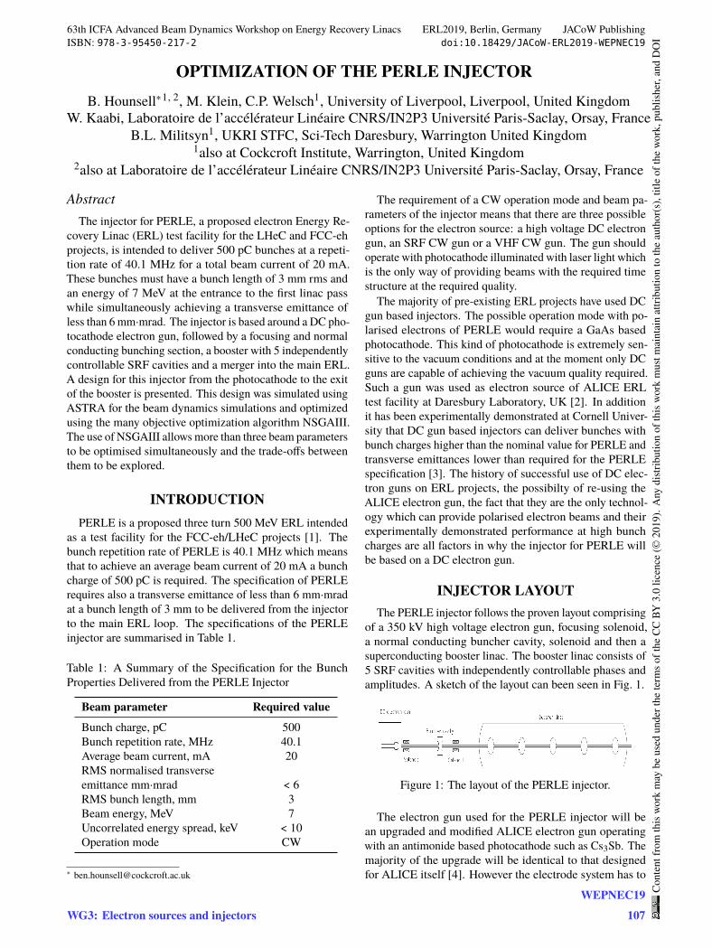
OPTIMIZATION OF THE PERLE INJECTORB. Hounsell∗1, 2, M. Klein, C.P. Welsch1, University of Liverpool, Liverpool, United Kingdom
W. Kaabi, Laboratoire de l’accélérateur Linéaire CNRS/IN2P3 Université Paris-Saclay, Orsay, FranceB.L. Militsyn1, UKRI STFC, Sci-Tech Daresbury, Warrington United Kingdom
1also at Cockcroft Institute, Warrington, United Kingdom2also at Laboratoire de l’accélérateur Linéaire CNRS/IN2P3 Université Paris-Saclay, Orsay, France
AbstractThe injector for PERLE, a proposed electron Energy Re-
covery Linac (ERL) test facility for the LHeC and FCC-ehprojects, is intended to deliver 500 pC bunches at a repeti-tion rate of 40.1 MHz for a total beam current of 20 mA.These bunches must have a bunch length of 3 mm rms andan energy of 7 MeV at the entrance to the first linac passwhile simultaneously achieving a transverse emittance ofless than 6 mm·mrad. The injector is based around a DC pho-tocathode electron gun, followed by a focusing and normalconducting bunching section, a booster with 5 independentlycontrollable SRF cavities and a merger into the main ERL.A design for this injector from the photocathode to the exitof the booster is presented. This design was simulated usingASTRA for the beam dynamics simulations and optimizedusing the many objective optimization algorithm NSGAIII.The use of NSGAIII allows more than three beam parametersto be optimised simultaneously and the trade-offs betweenthem to be explored.
INTRODUCTIONPERLE is a proposed three turn 500 MeV ERL intended
as a test facility for the FCC-eh/LHeC projects [1]. Thebunch repetition rate of PERLE is 40.1 MHz which meansthat to achieve an average beam current of 20 mA a bunchcharge of 500 pC is required. The specification of PERLErequires also a transverse emittance of less than 6 mm·mradat a bunch length of 3 mm to be delivered from the injectorto the main ERL loop. The specifications of the PERLEinjector are summarised in Table 1.
Table 1: A Summary of the Specification for the BunchProperties Delivered from the PERLE Injector
Beam parameter Required valueBunch charge, pC 500Bunch repetition rate, MHz 40.1Average beam current, mA 20RMS normalised transverseemittance mm·mrad < 6RMS bunch length, mm 3Beam energy, MeV 7Uncorrelated energy spread, keV < 10Operation mode CW
The requirement of a CW operation mode and beam pa-rameters of the injector means that there are three possibleoptions for the electron source: a high voltage DC electrongun, an SRF CW gun or a VHF CW gun. The gun shouldoperate with photocathode illuminated with laser light whichis the only way of providing beams with the required timestructure at the required quality.
The majority of pre-existing ERL projects have used DCgun based injectors. The possible operation mode with po-larised electrons of PERLE would require a GaAs basedphotocathode. This kind of photocathode is extremely sen-sitive to the vacuum conditions and at the moment only DCguns are capable of achieving the vacuum quality required.Such a gun was used as electron source of ALICE ERLtest facility at Daresbury Laboratory, UK [2]. In additionit has been experimentally demonstrated at Cornell Univer-sity that DC gun based injectors can deliver bunches withbunch charges higher than the nominal value for PERLE andtransverse emittances lower than required for the PERLEspecification [3]. The history of successful use of DC elec-tron guns on ERL projects, the possibilty of re-using theALICE electron gun, the fact that they are the only technol-ogy which can provide polarised electron beams and theirexperimentally demonstrated performance at high bunchcharges are all factors in why the injector for PERLE willbe based on a DC electron gun.
INJECTOR LAYOUTThe PERLE injector follows the proven layout comprising
of a 350 kV high voltage electron gun, focusing solenoid,a normal conducting buncher cavity, solenoid and then asuperconducting booster linac. The booster linac consists of5 SRF cavities with independently controllable phases andamplitudes. A sketch of the layout can been seen in Fig. 1.
Figure 1: The layout of the PERLE injector.
The electron gun used for the PERLE injector will bean upgraded and modified ALICE electron gun operatingwith an antimonide based photocathode such as Cs3Sb. Themajority of the upgrade will be identical to that designedfor ALICE itself [4]. However the electrode system has to
63th ICFA Advanced Beam Dynamics Workshop on Energy Recovery Linacs ERL2019, Berlin, Germany JACoW PublishingISBN: 978-3-95450-217-2 doi:10.18429/JACoW-ERL2019-WEPNEC19
WG3: Electron sources and injectorsWEPNEC19
107
Cont
entf
rom
this
wor
km
aybe
used
unde
rthe
term
soft
heCC
BY3.
0lic
ence
(©20
19).
Any
distr
ibut
ion
ofth
isw
ork
mus
tmai
ntai
nat
tribu
tion
toth
eau
thor
(s),
title
ofth
ew
ork,
publ
isher
,and
DO
I
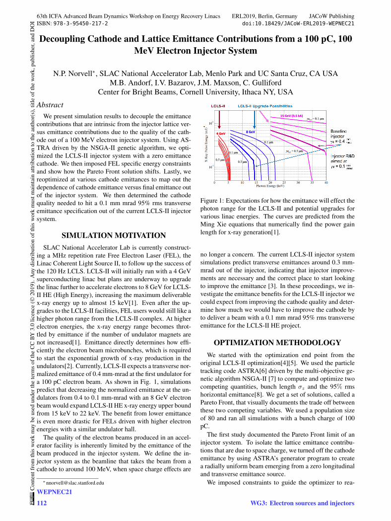
Decoupling Cathode and Lattice Emittance Contributions from a 100 pC, 100MeV Electron Injector System
N.P. Norvell∗, SLAC National Accelerator Lab, Menlo Park and UC Santa Cruz, CA USAM.B. Andorf, I.V. Bazarov, J.M. Maxson, C. Gulliford
Center for Bright Beams, Cornell University, Ithaca NY, USA
AbstractWe present simulation results to decouple the emittance
contributions that are intrinsic from the injector lattice ver-sus emittance contributions due to the quality of the cath-ode out of a 100 MeV electron injector system. Using AS-TRA driven by the NSGA-II genetic algorithm, we opti-mized the LCLS-II injector system with a zero emittancecathode. We then imposed FEL specific energy constraintsand show how the Pareto Front solution shifts. Lastly, wereoptimized at various cathode emittances to map out thedependence of cathode emittance versus final emittance outof the injector system. We then determined the cathodequality needed to hit a 0.1 mm mrad 95% rms transverseemittance specification out of the current LCLS-II injectorsystem.
SIMULATION MOTIVATIONSLAC National Accelerator Lab is currently construct-
ing a MHz repetition rate Free Electron Laser (FEL), theLinac Coherent Light Source II, to follow up the success ofthe 120 Hz LCLS. LCLS-II will initially run with a 4 GeVsuperconducting linac but plans are underway to upgradethe linac further to accelerate electrons to 8 GeV for LCLS-II HE (High Energy), increasing the maximum deliverablex-ray energy up to almost 15 keV[1]. Even after the up-grades to the LCLS-II facilities, FEL users would still like ahigher photon range from the LCLS-II complex. At higherelectron energies, the x-ray energy range becomes throt-tled by emittance if the number of undulator magnets arenot increased[1]. Emittance directly determines how effi-ciently the electron beam microbunches, which is requiredto start the exponential growth of x-ray production in theundulators[2]. Currently, LCLS-II expects a transverse nor-malized emittance of 0.4 mm-mrad at the first undulator fora 100 pC electron beam. As shown in Fig. 1, simulationspredict that decreasing the normalized emittance at the un-dulators from 0.4 to 0.1 mm-mrad with an 8 GeV electronbeam would expand LCLS-II HE x-ray energy upper boundfrom 15 keV to 22 keV. The benefit from lower emittanceis even more drastic for FELs driven with higher electronenergies with a similar undulator hall.
The quality of the electron beams produced in an accel-erator facility is inherently limited by the emittance of thebeam produced in the injector system. We define the in-jector system as the beamline that takes the beam from acathode to around 100 MeV, when space charge effects are
Figure 1: Expectations for how the emittance will effect thephoton range for the LCLS-II and potential upgrades forvarious linac energies. The curves are predicted from theMing Xie equations that numerically find the power gainlength for x-ray generation[1].
no longer a concern. The current LCLS-II injector systemsimulations predict transverse emittances around 0.3 mm-mrad out of the injector, indicating that injector improve-ments are necessary and the correct place to start lookingto improve the emittance [3]. In these proceedings, we in-vestigate the emittance benefits for the LCLS-II injector wecould expect from improving the cathode quality and deter-mine how much we would have to improve the cathode byto deliver a beam with a 0.1 mm mrad 95% rms transverseemittance for the LCLS-II HE project.
OPTIMIZATION METHODOLOGYWe started with the optimization end point from the
original LCLS-II optimization[4][5]. We used the particletracking code ASTRA[6] driven by the multi-objective ge-netic algorithm NSGA-II [7] to compute and optimize twocompeting quantities, bunch length σz and the 95% rmshorizontal emittance[8]. We get a set of solutions, called aPareto Front, that visually documents the trade off betweenthese two competing variables. We used a population sizeof 80 and ran all simulations with a bunch charge of 100pC.
The first study documented the Pareto Front limit of aninjector system. To isolate the lattice emittance contribu-tions that are due to space charge, we turned off the cathodeemittance by using ASTRA’s generator program to createa radially uniform beam emerging from a zero longitudinaland transverse emittance source.
We imposed constraints to guide the optimizer to rea-
63th ICFA Advanced Beam Dynamics Workshop on Energy Recovery Linacs ERL2019, Berlin, Germany JACoW PublishingISBN: 978-3-95450-217-2 doi:10.18429/JACoW-ERL2019-WEPNEC21
WEPNEC21112
Cont
entf
rom
this
wor
km
aybe
used
unde
rthe
term
soft
heCC
BY3.
0lic
ence
(©20
19).
Any
distr
ibut
ion
ofth
isw
ork
mus
tmai
ntai
nat
tribu
tion
toth
eau
thor
(s),
title
ofth
ew
ork,
publ
isher
,and
DO
I
WG3: Electron sources and injectors

BEAM IMPEDANCE STUDY ON A HARMONIC KICKER FOR THE CCROF JLEIC
Gunn Tae Park, Jiquan Guo, Shaoheng Wang, Robert Rimmer,Frank Marhauser, and Haipeng Wang
Thomas Jefferson National Laboratory, Newport News, VA 23606, USA
Abstract
The design of a high power prototype of the harmonickicker cavity for the Circulator Cooler Ring (CCR) of Jeffer-son Lab’s proposed Electron-Ion Collider (JLEIC) is com-plete and fabrication is underway. In this report we presentsome of the impedance studies assuming a high beam cur-rent of the JLEIC (∼ 0.76A average) to estimate the HOMpower dissipation and RF power requirement.
INTRODUCTION
A harmonic kicker cavity has been developed as a devicethat rapidly injects/extracts electron bunches into/out of theCCR of JLEIC [1], [2]. The engineering design of a highpower prototype cavity based on a quarter wave resonator(QWR) is complete (See Fig, 1) [3], [4]. The cavity optimiza-tion took into consideration the higher order mode (HOM)impedance spectrum so that the HOM power induced bypassing electron bunches is relatively low. In this report,we demonstrate that the beam-induced power due to theHOM’s is below ∼ 15W within a ± 10 mm transverse beamoffset from the ideal orbit. Consequently, HOM dampers arenot strictly needed. This analysis was carried out employingboth analytical calculation with the knowledge of impedanceof discrete eigenmodes and via a wake field simulation usingCST-MWS and CST-PS respectively [5]. In addition, weestimated the required power from the RF source neededto maintain a constant kick voltage with five deflecting har-monic modes.
Figure 1: CAD model of the harmonic kicker cavity.
HOM POWERThe induced HOM power dissipated in the cavity can
be evaluated in two ways. One is based on eigenmodes ofthe cavity computed numerically by the eigensolver of CST-MWS. Then the power associated with each eigenmode canbe calculated analytically. The other is taking into accountthat the cavity modes are continuously fed by the beambunch train. Therefore, the broadband coupling impedancespectrum (up to the first cutoff frequency of the beam pipe)has been evaluated using the wake field solver of the CST-PS,which allows to compute its power spectrum.
Time Structure of Beam Current in the CCRThe beam current in the CCR (for the parameters, see
[6]) comes in a series of bunch trains with a gap (emptybucket) between the trains as shown in Fig. 2a. In additionto the periodicity of the bunch at a repetition rate of ( 𝑓𝑏 =
476.3MHz), there is another periodicity arising from bunchtrain i.e., 𝑓𝑝 = 1.4MHz, which is very close to the CCRrevolution frequency. The beam current can be expanded ina Fourier series, i.e.:
𝐼 (𝑡) =∑𝑚
𝐼𝑚𝑒𝑖𝑚𝜔𝑝 𝑡 = 𝑐 + 𝑖𝑑, (1)
where 𝑐(𝑡) =∑𝑚
𝐼𝑚 cos (𝑚𝜔𝑝𝑡),
𝑑 (𝑡) =∑𝑚
𝐼𝑚 sin (𝑚𝜔𝑝𝑡),
where 𝐼𝑚 and 𝑚𝜔𝑝 with 𝜔𝑝 = 2𝜋 𝑓𝑝 are the amplitude andangular frequency of each mode of the current. The Fourierspectrum of the current is shown in Fig. 2b.
Power Evaluation via EigenmodesFor each eigenmode, the induced voltage with beam cur-
rent as given in the CCR can be written as
𝑉𝑏,𝑛, ∥ (𝑡) =
∫ 𝑡
−∞𝑑𝑡 ′ 𝐼 (𝑡 ′)
𝜔𝑛𝑅𝑛, ∥2𝑄𝑛,0
𝑒 (𝑖𝜔𝑛−1/𝜏𝑛) (𝑡−𝑡′)
=𝑅𝑛, ∥𝑄𝑛,0
𝑄𝑛,𝐿
(𝑎 + 𝑖𝑏
), (2)
where 𝑎(𝑡) =∑𝑚
𝐼𝑚√1 + Z2𝑚
cos (𝑚𝜔𝑝𝑡 − 𝜓𝑚),
𝑏(𝑡) =∑𝑚
𝐼𝑚√1 + Z2𝑚
sin (𝑚𝜔𝑝𝑡 − 𝜓𝑚),
Z𝑚 = 2𝑄𝐿 (𝑚𝜔𝑝
𝜔𝑛
− 1), 𝜓𝑚 = tan−1 Z𝑚.
63th ICFA Advanced Beam Dynamics Workshop on Energy Recovery Linacs ERL2019, Berlin, Germany JACoW PublishingISBN: 978-3-95450-217-2 doi:10.18429/JACoW-ERL2019-WEPNEC22
WEPNEC22116
Cont
entf
rom
this
wor
km
aybe
used
unde
rthe
term
soft
heCC
BY3.
0lic
ence
(©20
19).
Any
distr
ibut
ion
ofth
isw
ork
mus
tmai
ntai
nat
tribu
tion
toth
eau
thor
(s),
title
ofth
ew
ork,
publ
isher
,and
DO
I
WG3: Electron sources and injectors
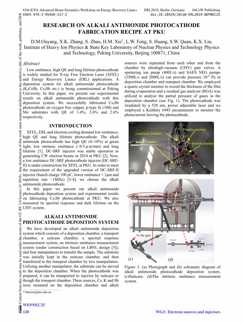
RESEARCH ON ALKALI ANTIMONIDE PHOTOCATHODE FABRICATION RECIPE AT PKU
D.M.Ouyang, X.K. Zhang, S. Zhao, H.M. Xie†, L.W. Feng, S. Huang, S.W. Quan, K.X. Liu, Institute of Heavy Ion Physics & State Key Laboratory of Nuclear Physics and Technology Physics
and Technology, Peking University, Beijing 100871, China
Abstract Low emittance, high QE and long lifetime photocathode
is widely studied for X-ray Free Electron Laser (XFEL) and Energy Recovery Linacs (ERL) applications. A deposition system for alkali antimonide photocathode (K2CsSb, Cs3Sb etc.) is being commissioned at Peking University. In this paper, we present our experimental results on alkali antimonide photocathode with this deposition system. We successfully fabricated Cs3Sb photocathode on oxygen free copper, p-type Si (100) and Mo substrates with QE of 1.4%, 2.6% and 2.6% respectively.
INTRONDUCTION XFEL, ERL and electron cooling demand low emittance,
high QE and long lifetime photocathode. The alkali antimoide photocathode has high QE (4~10%) at green light, low intrinsic emittance (~0.5 μ m/mm) and long lifetime [1]. DC-SRF injector was stable operation to generating CW electron beams in 2014 at PKU [2]. Now, a low emittance DC-SRF photocathode injector (DC-SRF-II) is under construction for XFEL at PKU. In order to meet the requirement of the upgraded version of DC-SRF-II injector (bunch charge 100 pC, lower emittance < 1𝜇m and repetition rate ~1MHz) [3-4], we choose the alkali antimonide photocathode.
In this paper we present our alkali antimonide photocathode deposition system and experimental results on fabricating Cs3Sb photocathode at PKU. We also measured its spectral response and dark lifetime on the UHV system.
ALKALI ANTIMONIDE PHOTOCATHODE DEPOSITION SYSTEM
We have developed an alkali antimonide deposition system which consists of a deposition chamber, a transport chamber, a suitcase chamber, a spectral response measurement system, an intrinsic emittance measurement system (under construction based on LBNL design [5]), and four manipulators to transfer the sample. The substrate was initially kept in the suitcase chamber, and then transferred to the transport chamber by two manipulators. Utilizing another manipulator, the substrate can be moved to the deposition chamber. When the photocathode was prepared, it can be transported to injector by suitcase or though the transport chamber. Three sources, Cs, K and Sb were mounted on the deposition chamber and alkali
sources were separated from each other and from the chamber by ultrahigh-vacuum (UHV) gate valves. A sputtering ion pump (400L/s) and SAES NEG pumps (3500L/s and 2000L/s) can provide pressure 10-9 Pa in deposition chamber and transport chamber. We employed a quartz crystal monitor to record the thickness of the film during evaporation and a residual gas analyser (RGA) was utilized to analyse the partial pressure of gases in the deposition chamber (see Fig. 1). The photocathode was irradiated by a 520 nm, power adjustable laser and we employed a Keithley 6485 picoammeter to monitor the photocurrent leaving the photocathode.
Figure 1: (a) Photograph and (b) schematic diagram of alkali antimonide photocathode deposition system. (c)Suitcase. (d)The intrinsic emittance measurement system.
(a)
(b)
(c) (d)
To the gun
Load-lock chamber
Source chamber
Transfer chamber
Deposition chamber
___________________________________________
63th ICFA Advanced Beam Dynamics Workshop on Energy Recovery Linacs ERL2019, Berlin, Germany JACoW PublishingISBN: 978-3-95450-217-2 doi:10.18429/JACoW-ERL2019-WEPNEC25
WEPNEC25120
Cont
entf
rom
this
wor
km
aybe
used
unde
rthe
term
soft
heCC
BY3.
0lic
ence
(©20
19).
Any
distr
ibut
ion
ofth
isw
ork
mus
tmai
ntai
nat
tribu
tion
toth
eau
thor
(s),
title
ofth
ew
ork,
publ
isher
,and
DO
I
WG3: Electron sources and injectors
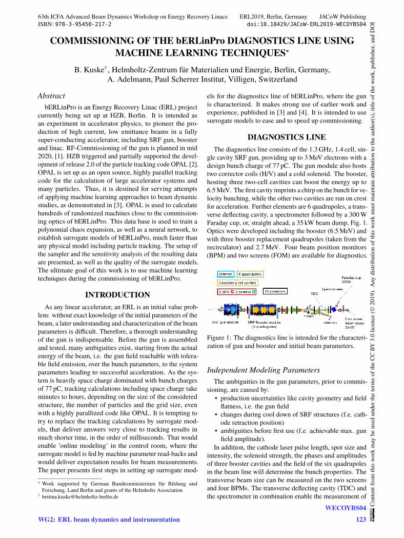
COMMISSIONING OF THE bERLinPro DIAGNOSTICS LINE USINGMACHINE LEARNING TECHNIQUES∗
B. Kuske† , Helmholtz-Zentrum für Materialien und Energie, Berlin, Germany,A. Adelmann, Paul Scherrer Institut, Villigen, Switzerland
AbstractbERLinPro is an Energy Recovery Linac (ERL) project
currently being set up at HZB, Berlin. It is intended asan experiment in accelerator physics, to pioneer the pro-duction of high current, low emittance beams in a fullysuper-conducting accelerator, including SRF gun, boosterand linac. RF-Commissioning of the gun is planned in mid2020, [1]. HZB triggered and partially supported the devel-opment of release 2.0 of the particle tracking code OPAL [2].OPAL is set up as an open source, highly parallel trackingcode for the calculation of large accelerator systems andmany particles. Thus, it is destined for serving attemptsof applying machine learning approaches to beam dynamicstudies, as demonstrated in [3]. OPAL is used to calculatehundreds of randomized machines close to the commission-ing optics of bERLinPro. This data base is used to train apolynomial chaos expansion, as well as a neural network, toestablish surrogate models of bERLinPro, much faster thanany physical model including particle tracking. The setup ofthe sampler and the sensitivity analysis of the resulting dataare presented, as well as the quality of the surrogate models.The ultimate goal of this work is to use machine learningtechniques during the commissioning of bERLinPro.
INTRODUCTIONAs any linear accelerator, an ERL is an initial value prob-
lem: without exact knowledge of the initial parameters of thebeam, a later understanding and characterization of the beamparameters is difficult. Therefore, a thorough understandingof the gun is indispensable. Before the gun is assembledand tested, many ambiguities exist, starting from the actualenergy of the beam, i.e. the gun field reachable with tolera-ble field emission, over the bunch parameters, to the systemparameters leading to successful acceleration. As the sys-tem is heavily space charge dominated with bunch chargesof 77 pC, tracking calculations including space charge takeminutes to hours, depending on the size of the consideredstructure, the number of particles and the grid size, evenwith a highly parallized code like OPAL. It is tempting totry to replace the tracking calculations by surrogate mod-els, that deliver answers very close to tracking results inmuch shorter time, in the order of milliseconds. That wouldenable ’online modeling’ in the control room, where thesurrogate model is fed by machine parameter read-backs andwould deliver expectation results for beam measurements.The paper presents first steps in setting up surrogate mod-
∗ Work supported by German Bundesministerium für Bildung undForschung, Land Berlin and grants of the Helmholtz Association
els for the diagnostics line of bERLinPro, where the gunis characterized. It makes strong use of earlier work andexperience, published in [3] and [4]. It is intended to usesurrogate models to ease and to speed up commissioning.
DIAGNOSTICS LINEThe diagnostics line consists of the 1.3GHz, 1.4 cell, sin-
gle cavity SRF gun, providing up to 3MeV electrons with adesign bunch charge of 77 pC. The gun module also hoststwo corrector coils (H/V) and a cold solenoid. The booster,hosting three two-cell cavities can boost the energy up to6.5MeV. The first cavity imprints a chirp on the bunch for ve-locity bunching, while the other two cavities are run on crestfor acceleration. Further elements are 6 quadrupoles, a trans-verse deflecting cavity, a spectrometer followed by a 300WFaraday cup, or, straight ahead, a 35 kW beam dump, Fig. 1.Optics were developed including the booster (6.5MeV) andwith three booster replacement quadrupoles (taken from therecirculator) and 2.7MeV. Four beam position monitors(BPM) and two screens (FOM) are available for diagnostics.
Figure 1: The diagnostics line is intended for the characteri-zation of gun and booster and initial beam parameters.
Independent Modeling ParametersThe ambiguities in the gun parameters, prior to commis-
sioning, are caused by:• production uncertainties like cavity geometry and fieldflatness, i.e. the gun field
• changes during cool down of SRF structures (f.e. cath-ode retraction position)
• ambiguities before first use (f.e. achievable max. gunfield amplitude).
In addition, the cathode laser pulse length, spot size andintensity, the solenoid strength, the phases and amplitudesof three booster cavities and the field of the six quadrupolesin the beam line will determine the bunch properties. Thetransverse beam size can be measured on the two screensand four BPMs. The transverse deflecting cavity (TDC) andthe spectrometer in combination enable the measurement of
63th ICFA Advanced Beam Dynamics Workshop on Energy Recovery Linacs ERL2019, Berlin, Germany JACoW PublishingISBN: 978-3-95450-217-2 doi:10.18429/JACoW-ERL2019-WECOYBS04
WG2: ERL beam dynamics and instrumentationWECOYBS04
123
Cont
entf
rom
this
wor
km
aybe
used
unde
rthe
term
soft
heCC
BY3.
0lic
ence
(©20
19).
Any
distr
ibut
ion
ofth
isw
ork
mus
tmai
ntai
nat
tribu
tion
toth
eau
thor
(s),
title
ofth
ew
ork,
publ
isher
,and
DO
I
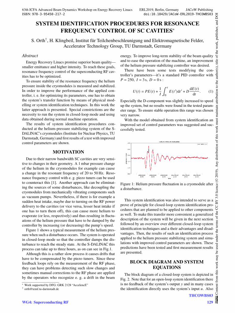
SYSTEM IDENTIFICATION PROCEDURES FOR RESONANCEFREQUENCY CONTROL OF SC CAVITIES∗
S. Orth†, H. Klingbeil, Institut für Teilchenbeschleunigung und Elektromagnetische Felder,Accelerator Technology Group, TU Darmstadt, Germany
AbstractEnergy Recovery Linacs promise superior beam quality—
smaller emittance and higher intensity. To reach these goals,resonance frequency control of the superconducting RF cav-ities has to be optimized.
To ensure stability of the resonance frequency the heliumpressure inside the cryomodules is measured and stabilized.In order to improve the performance of the applied con-troller, i. e. for optimizing its parameters, one has to obtainthe system’s transfer function by means of physical mod-elling or system identification techniques. In this work thelatter approach is presented. Special constrictions are thenecessity to run the system in closed-loop mode and usingdata obtained during normal machine operation.
The results of system identification procedures con-ducted at the helium-pressure stabilizing system of the S-DALINAC’s cryomodules (Institute for Nuclear Physics, TUDarmstadt, Germany) and first results of a test with improvedcontrol parameters are shown.
MOTIVATIONDue to their narrow bandwidth SC cavities are very sensi-
tive to changes in their geometry. A 1 mbar pressure changeof the helium in the cryomodules for example can causea change in the resonant frequency of 20 to 50 Hz. Reso-nance frequency control with e. g. piezo tuners can be usedto counteract this [1]. Another approach can be eliminat-ing the sources of some disturbances, like decoupling thecryomodules from mechanically vibrating components suchas vacuum pumps. Nevertheless, if there is for example asudden heat intake, maybe due to turning on the RF powerdelivery to the cavities (or vice versa, lesser heat intake ifone has to turn them off), this can cause more helium toevaporate (or less, respectively) and thus resulting in fluctu-ations of the helium pressure that have to be damped by thecontroller by increasing (or decreasing) the pump’s speed.
Figure 1 shows a typical measurement of the helium pres-sure when such a disturbance occurs. The system is operatedin closed-loop mode so that the controller damps the dis-turbance to reach the steady state. At the S-DALINAC thisprocess can take up to three hours, as on can see in Fig.1.
Although this is a rather slow process it causes drifts thathave to be compensated by the piezo tuners. Since thesefeedback loops rely on the measurement of the RF phase,they can have problems detecting such slow changes andsometimes manual corrections to the RF phase are appliedby the operators who recognize e. g. a drift in the beam∗ Work supported by DFG: GRK 2128 “AccelencE”† [email protected]
energy. To improve long-term stability of the beam qualityand to ease the operation of the machine, an improvementof the helium pressure stabilizing controller was desired.
There have been some tests modifying the con-troller’s parameters—it’s a standard PID controller with𝑃 = 250, 𝐼 = 3 s, 𝐷 = 0 s :
𝑈 (𝑡) = 𝑃𝐸 (𝑡) + 1
𝐼
∫ 𝑡
0
𝐸 (𝑡 ′)d𝑡 ′ + 𝐷 d𝐸 (𝑡)d𝑡
. (1)
Especially the D-component was slightly increased to speedup the system, but no results were found in the tested param-eter range. To ensure stable operation this range was chosenvery narrow.
With the model obtained from system identification animproved set of control parameters was suggested and suc-cessfully tested.
Figure 1: Helium pressure fluctuation in a cryomodule aftera disturbance.
This system identification was also intended to serve as aprove of principle for closed-loop system identification pro-cedures that are planned to be applied to other componentsas well. To make this transfer more convenient a generalizeddescription of the system will be given in the next sectionfollowed by an overview over different closed-loop systemidentification techniques and a their advantages and disad-vantages. Then, the results of such an identification processapplied to the helium pressure stabilizing system and simu-lations with improved control parameters are shown. Thesepredictions have been tested and first measurement resultsare presented.
BLOCK DIAGRAM AND SYSTEMEQUATIONS
The block diagram of a closed-loop system is depicted inFig. 2. Note that for an open-loop system identification thereis no feedback of the system’s output 𝑦 and in many casesthe identification directly uses the system’s input 𝑢. Also
63th ICFA Advanced Beam Dynamics Workshop on Energy Recovery Linacs ERL2019, Berlin, Germany JACoW PublishingISBN: 978-3-95450-217-2 doi:10.18429/JACoW-ERL2019-THCOWBS03
WG4: Superconducting RFTHCOWBS03
129
Cont
entf
rom
this
wor
km
aybe
used
unde
rthe
term
soft
heCC
BY3.
0lic
ence
(©20
19).
Any
distr
ibut
ion
ofth
isw
ork
mus
tmai
ntai
nat
tribu
tion
toth
eau
thor
(s),
title
ofth
ew
ork,
publ
isher
,and
DO
I
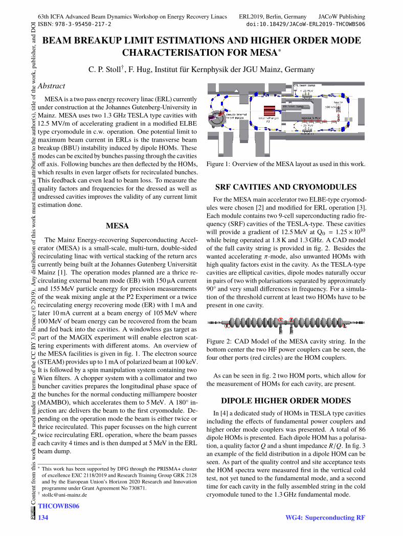
BEAM BREAKUP LIMIT ESTIMATIONS AND HIGHER ORDER MODECHARACTERISATION FOR MESA∗
C. P. Stoll†, F. Hug, Institut für Kernphysik der JGU Mainz, Germany
AbstractMESA is a two pass energy recovery linac (ERL) currently
under construction at the Johannes Gutenberg-University inMainz. MESA uses two 1.3 GHz TESLA type cavities with12.5 MV/m of accelerating gradient in a modified ELBEtype cryomodule in c.w. operation. One potential limit tomaximum beam current in ERLs is the transverse beambreakup (BBU) instability induced by dipole HOMs. Thesemodes can be excited by bunches passing through the cavitiesoff axis. Following bunches are then deflected by the HOMs,which results in even larger offsets for recirculated bunches.This feedback can even lead to beam loss. To measure thequality factors and frequencies for the dressed as well asundressed cavities improves the validity of any current limitestimation done.
MESAThe Mainz Energy-recovering Superconducting Accel-
erator (MESA) is a small-scale, multi-turn, double-sidedrecirculating linac with vertical stacking of the return arcscurrently being built at the Johannes Gutenberg UniversitätMainz [1]. The operation modes planned are a thrice re-circulating external beam mode (EB) with 150 µA currentand 155 MeV particle energy for precision measurementsof the weak mixing angle at the P2 Experiment or a twicerecirculating energy recovering mode (ER) with 1 mA andlater 10 mA current at a beam energy of 105 MeV where100 MeV of beam energy can be recovered from the beamand fed back into the cavities. A windowless gas target aspart of the MAGIX experiment will enable electron scat-tering experiments with different atoms. An overview ofthe MESA facilities is given in fig. 1. The electron source(STEAM) provides up to 1 mA of polarized beam at 100 keV.It is followed by a spin manipulation system containing twoWien filters. A chopper system with a collimator and twobuncher cavities prepares the longitudinal phase space ofthe bunches for the normal conducting milliampere booster(MAMBO), which accelerates them to 5 MeV. A 180° in-jection arc delivers the beam to the first cryomodule. De-pending on the operation mode the beam is either twice orthrice recirculated. This paper focusses on the high currenttwice recirculating ERL operation, where the beam passeseach cavity 4 times and is then dumped at 5 MeV in the ERLbeam dump.
∗ This work has been supported by DFG through the PRISMA+ clusterof excellence EXC 2118/2019 and Research Training Group GRK 2128and by the European Union’s Horizon 2020 Research and Innovationprogramme under Grant Agreement No 730871.
Figure 1: Overview of the MESA layout as used in this work.
SRF CAVITIES AND CRYOMODULESFor the MESA main accelerator two ELBE-type cryomod-
ules were chosen [2] and modified for ERL operation [3].Each module contains two 9-cell superconducting radio fre-quency (SRF) cavities of the TESLA-type. These cavitieswill provide a gradient of 12.5 MeV at Q0 = 1.25 × 10¹⁰
while being operated at 1.8 K and 1.3 GHz. A CAD modelof the full cavity string is provided in fig. 2. Besides thewanted accelerating 𝜋-mode, also unwanted HOMs withhigh quality factors exist in the cavity. As the TESLA-typecavities are elliptical cavities, dipole modes naturally occurin pairs of two with polarisations separated by approximately90° and very small differences in frequency. For a simula-tion of the threshold current at least two HOMs have to bepresent in one cavity.
Figure 2: CAD Model of the MESA cavity string. In thebottom center the two HF power couplers can be seen, thefour other ports (red circles) are the HOM couplers.
As can be seen in fig. 2 two HOM ports, which allow forthe measurement of HOMs for each cavity, are present.
DIPOLE HIGHER ORDER MODESIn [4] a dedicated study of HOMs in TESLA type cavities
including the effects of fundamental power couplers andhigher order mode couplers was presented. A total of 86dipole HOMs is presented. Each dipole HOM has a polarisa-tion, a quality factor 𝑄 and a shunt impedance 𝑅/𝑄. In fig. 3an example of the field distribution in a dipole HOM can beseen. As part of the quality control and site acceptance teststhe HOM spectra were measured first in the vertical coldtest, not yet tuned to the fundamental mode, and a secondtime for each cavity in the fully assembled string in the coldcryomodule tuned to the 1.3 GHz fundamental mode.
63th ICFA Advanced Beam Dynamics Workshop on Energy Recovery Linacs ERL2019, Berlin, Germany JACoW PublishingISBN: 978-3-95450-217-2 doi:10.18429/JACoW-ERL2019-THCOWBS06
THCOWBS06134
Cont
entf
rom
this
wor
km
aybe
used
unde
rthe
term
soft
heCC
BY3.
0lic
ence
(©20
19).
Any
distr
ibut
ion
ofth
isw
ork
mus
tmai
ntai
nat
tribu
tion
toth
eau
thor
(s),
title
ofth
ew
ork,
publ
isher
,and
DO
I
WG4: Superconducting RF
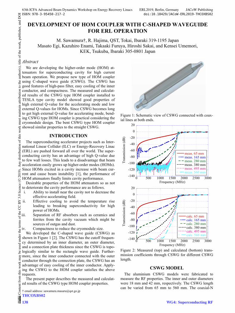
DEVELOPMENT OF HOM COUPLER WITH C-SHAPED WAVEGUIDE FOR ERL OPERATION
M. Sawamura†, R. Hajima, QST, Tokai, Ibaraki 319-1195 Japan Masato Egi, Kazuhiro Enami, Takaaki Furuya, Hiroshi Sakai, and Kensei Umemori,
KEK, Tsukuba, Ibaraki 305-0801 Japan
Abstract We are developing the higher-order mode (HOM) at-
tenuators for superconducting cavity for high current beam operation. We propose new type of HOM coupler using C-shaped wave guide (CSWG). The CSWG has good features of high-pass filter, easy cooling of the inner conductor, and compactness. The measured and calculat-ed results of the CSWG type HOM coupler installed to TESLA type cavity model showed good properties of high external Q-value for the accelerating mode and low external Q-values for HOMs. Since CSWG becomes long to get high external Q-value for accelerating mode, bend-ing CSWG type HOM coupler is practical considering the cryomodule design. The bent CSWG type HOM coupler showed similar properties to the straight CSWG.
INTRODUCTION The superconducting accelerator projects such as Inter-
national Linear Collider (ILC) or Energy-Recovery Linac (ERL) are pushed forward all over the world. The super-conducting cavity has an advantage of high Q-value due to few wall losses. This leads to a disadvantage that beam acceleration easily grows up higher-order modes (HOMs). Since HOMs excited in a cavity increase with beam cur-rent and cause beam instability [1], the performance of HOM attenuators finally limits cavity performance.
Desirable properties of the HOM attenuators so as not to deteriorate the cavity performance are as follows. i. Ability to install near the cavity not to decrease the
effective accelerating field. ii. Effective cooling to avoid the temperature rise
leading to breaking superconductivity for high power of HOMs.
iii. Separation of RF absorbers such as ceramics and ferrites from the cavity vacuum which might be sources of outgas and dust.
iv. Compactness to reduce the cryomodule size. We developed the C-shaped wave guide (CSWG) as
shown in Figure 1 [2]. The CSWG has the cutoff frequen-cy determined by an inner diameter, an outer diameter, and a connection plate thickness since the CSWG is topo-logically similar to the rectangle wave guide. Further-more, since the inner conductor connected with the outer conductor through the connection plate, the CSWG has an advantage of easy cooling of the inner conductor. Apply-ing the CSWG to the HOM coupler satisfies the above requests.
The present paper describes the measured and calculat-ed results of the CSWG type HOM coupler properties.
Figure 1: Schematic view of CSWG connected with coax-ial lines at both ends.
Figure 2: Measured (top) and calculated (bottom) trans-mission coefficients through CSWG for different CSWG length.
CSWG MODEL The aluminium CSWG models were fabricated to
measure the RF properties. The inner and outer diameters were 18 mm and 42 mm, respectively. The CSWG length can be varied from 65 mm to 560 mm. The coaxial-N
-140
-120
-100
-80
-60
-40
-20
0
20
0 500 1000 1500 2000 2500 3000
meas. 65 mmmeas. 165 mmmeas. 280 mmmeas. 380 mmmeas. 495 mmmeas. 560 mm
Tra
nsm
issi
on (
dB)
Frequency (MHz)
-140
-120
-100
-80
-60
-40
-20
0
20
0 500 1000 1500 2000 2500 3000
calc. 65 mmcalc. 165 mmcalc. 280 mmcalc. 380 mmcalc. 495 mmcalc. 560 mm
Tra
nsm
issi
on (
dB)
Frequency (MHz)
† email address: [email protected]
63th ICFA Advanced Beam Dynamics Workshop on Energy Recovery Linacs ERL2019, Berlin, Germany JACoW PublishingISBN: 978-3-95450-217-2 doi:10.18429/JACoW-ERL2019-THCOXBS02
THCOXBS02138
Cont
entf
rom
this
wor
km
aybe
used
unde
rthe
term
soft
heCC
BY3.
0lic
ence
(©20
19).
Any
distr
ibut
ion
ofth
isw
ork
mus
tmai
ntai
nat
tribu
tion
toth
eau
thor
(s),
title
ofth
ew
ork,
publ
isher
,and
DO
I
WG4: Superconducting RF
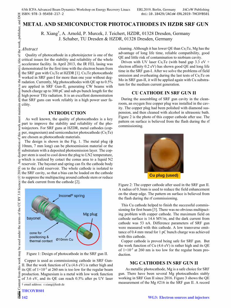
METAL AND SEMICONDUCTOR PHOTOCATHODES IN HZDR SRF GUN
R. Xiang†, A. Arnold, P. Murcek, J. Teichert, HZDR, 01328 Dresden, Germany J. Schaber, TU Dresden & HZDR, 01328 Dresden, Germany
Abstract Quality of photocathode in a photoinjector is one of the
critical issues for the stability and reliability of the whole accelerator facility. In April 2013, the IR FEL lasing was demonstrated for the first time with the electron beam from the SRF gun with Cs2Te at HZDR [1]. Cs2Te photocathode worked in SRF gun-I for more than one year without deg-radation. Currently, Mg photocathodes with QE up to 0.5% are applied in SRF Gun-II, generating CW beams with bunch charge up to 300 pC and sub-ps bunch length for the high power THz radiation. It is an excellent demonstration that SRF guns can work reliably in a high power user fa-cility.
INTRODUCTION As well known, the quality of photocathodes is a key
part to improve the stability and reliability of the pho-toinjectors. For SRF guns at HZDR, metal cathodes (cop-per, magnesium) and semiconductor photocathode (Cs2Te) are chosen as photocathode materials.
The design is shown in the Fig. 1. The metal plug (ɸ 10mm, 7 mm long) can be photoemission material or the substratum with a deposited photoemission layer. The cop-per stem is used to cool down the plug to LN2 temperature, which is realized by cotact the conus area to a liquid N2 reservoir. The bayonet and spring can fix the cathode body on to the cold reservoir. The whole cathode is isolated to the SRF cavity, so that a bias can be loaded on the cathode to suppress the multipacting around cathode stem or reduce the dark current from the cathode [2].
Figure 1: Design of photocathode in the SRF gun II.
Copper is used as commissioning cathode in SRF Gun-II. But the work function of Cu (4.6 eV) is rather high and its QE of 1×10⁻⁵ at 260 nm is too low for the regular beam production. Magnesium is a metal with low work function of 3.6 eV, and its QE can reach 0.5% after ps UV laser
cleaning. Although it has lower QE than Cs2Te, Mg has the advantage of long life time, reliable compatibility, good QE and little risk of contamination to niobium cavity.
Driven with UV laser Cs2Te (with band gap 3.3 eV + electron affinity 0.2 eV) has shown good QE and long life time in the SRF gun-I. After we solve the problems of field emission and overheating during the last tests of Cs2Te on Mo in SRF gun-II, it will be applied again with Cu substra-tum for the medium current generation.
CU CATHODE IN SRF GUN II During the assembling of SRF gun cavity in the clean-
room, an oxygen free copper plug was installed in the cav-ity. The copper plug had been polished with diamond sus-pension, and then cleaned with alcohol in ultrasonic bath. Figure 2 is the photo of this copper cathode after use. The pattern on surface is believed from the flash during the rf commissioning.
Figure 2: The copper cathode after used in the SRF gun II. A radius of 0.3mm is used to reduce the field enhancement on the sharp edge. The pattern on surface is believed from the flash during the rf commissioning.
This Cu cathode helped to finish the successful commis-sioning for first beam [3]. There was no obvious multipact-ing problem with copper cathode. The maximum field on cathode surface is 14.6 MV/m, and the dark current from cathode was 53 nA. Difference parameters of SRF gun were measured with this cathode. A low transverse emit-tance of 0.4 mmꞏmrad for 1 pC bunch charge was achieved with this cathode.
Copper cathode is proved being safe for SRF gun. But the work function of Cu (4.6 eV) is rather high and its QE of 1×10⁻⁵ at 260 nm is too low for the regular beam pro-duction.
MG CATHODES IN SRF GUN II As metallic photocathode, Mg is a safe choice for SRF
gun. There have been several Mg photocathodes stably working in SRF Gun II since 2016. Figure 3 shows the QE measurement of the Mg #216 in the SRF gun II. A record ____________________________________________
† email address: [email protected]
63th ICFA Advanced Beam Dynamics Workshop on Energy Recovery Linacs ERL2019, Berlin, Germany JACoW PublishingISBN: 978-3-95450-217-2 doi:10.18429/JACoW-ERL2019-THCOYBS01
THCOYBS01142
Cont
entf
rom
this
wor
km
aybe
used
unde
rthe
term
soft
heCC
BY3.
0lic
ence
(©20
19).
Any
distr
ibut
ion
ofth
isw
ork
mus
tmai
ntai
nat
tribu
tion
toth
eau
thor
(s),
title
ofth
ew
ork,
publ
isher
,and
DO
I
WG3: Electron sources and injectors

HIGH CHARGE HIGH CURRENT BEAM FROM BNL 113 MHZ SRF GUN* I. Pinayev†, I. Ben-Zvi, J.C. Brutus, M. Gaowei, T. Hayes, Y. Jing, V.N. Litvinenko1, J. Ma, K. Mi-hara1, G. Narayan, I. Petrushina1, F. Severino, K. Shih1, J. Skaritka, E. Wang, G. Wang, Y.H. Wu1,
Brookhaven National Laboratory, Upton NY, U.S.A. 1also at Stony Brook University, Stony Brook NY, U.S.A.
Abstract The 113 MHz superconducting gun is used an electron
source for the coherent electron cooling experiment. The unique feature of the gun is that a photocathode is held at room temperature. It allowed to preserve the quantum effi-ciency of Cs2KSb cathode which is adversely affected by cryogenic temperatures. Relatively low frequency permit-ted fully realize the accelerating field gradient what in turn helps to achieve 10 nC charge and 0.3 microns normalized emittance. We present the achieved performance and oper-ational experience as well.
GUN DESIGN The injector is an essential part of any accelerator, and
the quality of the produced beams completely relies on its performance. Among the well-known electrostatic (DC) and normal-conducting (NC) RF photo-guns, the injectors based on an SRF cavity are rapidly gaining popularity in the generation of the high-brightness high-quality beams.
The idea of utilizing the SRF technology brings ad-vantages and challenges [1, 2]. The biggest advantage is the reduced power losses (orders of magnitude lower com-pared to a NC cavity) which allow for reliable operation in continuous wave (CW) regime and generation of beams with high average current, providing a higher accelerating gradient. Another advantage is an excellent vacuum condi-tions inside the cavity which serves ad huge cryopump.
However, introduction of a photocathode into the SRF environment causes several complications: since the pho-tocathode has to be replaced throughout the operation of the gun, the area around the cathode creates a condition for RF power leakage which has to be taken care of. To keep the power within the cavity, an RF choke filter has to be designed for this purpose.
Moreover, the cathodes are generally kept at room tem-perature creating an additional heat leak between the cold surface of the cavity and the warm cathode.
We utilized quarter-wave resonator (QWR) based geom-etry for our gun. The QWR cavities are specifically suita-ble for operation at low frequencies which allow for a gen-eration of long bunches. This fact is beneficial for the re-duction of the space charge effect in the initial stages of the beam generation, allowing to achieve higher charge per bunch. The accelerating gap in such a cavity is relatively short compared to the wavelength, which makes the field distribution in the gap close to constant. To a degree, such
SRF guns are similar to DC guns but offer both high accel-erating gradient and higher beam energy at the gun exit. The main RF parameters of the gun can be found in Table 1.
Table 1: RF Parameters of the Gun Parameter Value Frequency, MHz 113 Quality factor w/o cathode 3.5×10⁹ R/Q, Ω 126 Geometry factor, W 38.2 Operating temperature, K 4.2 Accelerating voltage, MV 1.25 (1.7) The geometry of the SRF gun is shown in Fig. 1. The
cavity body is made of bulk Nb, and, as all of the QWR geometries, has “outer conductor” and “inner conductor” parts due to the nature of this type of a cavity. The “inner conductor” is hollow and accommodates the system of the cathode insertion and extraction. The accelerating electric field is concentrated between the front wall of the cavity and the rounded part of the “inner conductor,” which we denote as the cavity “nose”. The inset in the Fig. 1 shows in detail the location of the cathode puck in the cavity nose.
The necessary half-wavelength RF choke for the reduc-tion of the power leakage incorporates a hollow stainless-steel cathode stalk which allows insertion of a cathode puck [3, 4]. The cathode stalk is coated with layers of cop-per and gold to reduce heat emission into the 4 K system. It is kept at room temperature by circulating water in the channel soldered to the stalk.
The stalk does not have direct physical contact with the cold center conductor of the cavity, thus reducing the leak-age of heat into the cavity only allowing the exchange of the radiated heat. The stalk is shorted at the far end to serve as a choke filter. The choke reduces the penetration of the RF field, and minimizes the voltage drop between the cath-ode and the cavity's center conductor. The gap between the stalk and the cavity nose at the entrance of the cavity is only 3.56 mm. The length of the stalk was shortened to ac-count for the capacitance created by this small gap. The impedance transformer in the middle of the stalk is used to reduce the current through the short, which includes a coated bellow.
A pick-up antenna for measuring the RF voltage is lo-cated outside of the gun cryostat and is weakly coupled to the choke. The axial position of the stalk tip and, therefore, the photocathode surface with respect to the cavity nose can be manually adjusted. The latter provides us with an opportunity to optimize the initial focusing of the electron beam.
___________________________________________
* Work supported by Brookhaven Science Associates, LLC under ContractNo. DE-AC02-98CH10886 with the U.S. Department of Energy. † [email protected]
63th ICFA Advanced Beam Dynamics Workshop on Energy Recovery Linacs ERL2019, Berlin, Germany JACoW PublishingISBN: 978-3-95450-217-2 doi:10.18429/JACoW-ERL2019-THCOYBS02
WG3: Electron sources and injectorsTHCOYBS02
145
Cont
entf
rom
this
wor
km
aybe
used
unde
rthe
term
soft
heCC
BY3.
0lic
ence
(©20
19).
Any
distr
ibut
ion
ofth
isw
ork
mus
tmai
ntai
nat
tribu
tion
toth
eau
thor
(s),
title
ofth
ew
ork,
publ
isher
,and
DO
I

ESSENTIAL INSTRUMENTATION FOR CHARACTERIZATION OF ERLBEAMS∗
N. Banerjee†, A. Bartnik, K. Deitrick, J. Dobbins, C. Gulliford, G. Hoffstaetter,Cornell Laboratory for Accelerator-Based Sciences and Education, Ithaca, USA
J. S. Berg, S. Brooks, R. Michnoff,Brookhaven National Laboratory, Upton, USA
AbstractThe typical requirement of Energy Recovery Linacs to
produce beams with high repetition rate and high bunchcharge presents unique demands on beam diagnostics. ERLsbeing quite sensitive to time of flight effects necessitate theuse of beam arrival time monitors along with typical posi-tion detection. Being subjected to a plethora of dynamiceffects, both longitudinal and transverse phase space moni-toring of the beam becomes quite important. Additionally,beam halo plays an important role determining the overalltransmission. Consequently, we also need to characterizehalo both directly using sophisticated beam viewers and in-directly using radiation monitors. In this talk, I will describethe instrumentation essential to ERL operation using theCornell-BNL ERL Test Accelerator (CBETA) as a pertinentexample.
INTRODUCTIONThe unique diagnostic requirements for beams produced
in Energy Recovery Linacs (ERLs) stem from the hybridnature of these accelerators which combine aspects of bothLinacs and storage rings. Just like their Linac counterparts,ERLs produce very bright beams with typical normalizedtransverse emittance of a few microns. On the other hand,the requirements on longitudinal distribution of the beamdepends on particular applications. A survey of beam param-eters [1] of different ERL projects around the world revealsbunch lengths from less than a pico-second for light sources,up to 50 ps for the Coherent electron Cooler proposed foreRHIC. Just like storage rings, ERLs are CW high currentmachines with large beam power. However, beam is contin-uously produced in ERLs while rings can only hold a finiteamount of charge inside. This difference is very important inthe context of machine protection. Consequently, the list ofdiagnostics essential to ERL beam operations must includemonitoring of all these aspects.
Apart from the distinguishing features of the beams, ERLsare sensitive to time of flight errors and losses. The timeof flight of the beam in the return loop needs to be withinthe target value with narrow tolerances in order to ensurecorrect arrival phase in the accelerating cavities. This in turnestablishes correct beam energies and zero average beamloading [2], which is crucial for sustaining high currents. In
∗ This work was supported by the New York State Energy Research andDevelopment Authority.
this way, ERLs are operationally time of flight spectrome-ters. [3] Further, ERLs are designed for high average beampower up to mega-watts, so even modest losses can resultin large radiation and thermal load on machine components.Consequently halo characterization and bunch arrival timemeasurements are crucial for high current operations alongwith the usual measurement of the core and the transverseposition of the beam.
The Cornell-BNL ERL Test Accelerator (CBETA) [4] is a4-turn superconducting ERL which has been constructed un-der the collaboration of Cornell University and BrookhavenNational Laboratories and is currently being commissioned.With a target injection current of 40 mA and the top energyof 150 MeV, the diagnostics used in this accelerator servesas a representative example of essential instrumentation cru-cial to ERL operation. In the next section, we describe howwe measure the beam centroid in CBETA. Then we explainvarious methods of observing the phase space distributionof the core of the beam. After this, we list instrumentationto detect beam halo and loss, including the equipment pro-tection system. Finally we describe other miscellaneousdiagnostics.
BEAM CENTROIDBeam Position Monitors (BPMs) detect the position of
the centroid of the bunch both in space and time. In terms ofhardware, BPMs can be broadband devices such as buttonBPMs and striplines such as the ones used in CBETA, or theymay work as resonant cavities which are narrowband. Inthe case of broadband monitors, the image charges inducedby the bunches are electrically coupled to pickups and therelative amplitudes and phases of the detected impulses canbe used to measure beam position. On the other hand cavityBPMs work by measuring the amplitudes and phases ofspecific resonant modes excited by the beam and can be usedfor very precise measurements. [5] ERLs pose an additionalrequirement on BPMs to be able to detect multiple beams atthe same time, which is especially true in CBETA which hasa Non Scaling Fixed Field Alternating (NS FFA) [6] returnloop hosting 7 beams at the same time.
We use both time and frequency domain techniques forsignal processing on broadband BPMs in CBETA. The timedomain technique first uses a custom low pass filter with acut off frequency at 800 MHz to broaden and smooth theincoming wideband signal from the buttons. Then after aprogrammable gain, we digitize the signal using a 400 MSPSADC, after which a FPGA processes the data. We acquire
63th ICFA Advanced Beam Dynamics Workshop on Energy Recovery Linacs ERL2019, Berlin, Germany JACoW PublishingISBN: 978-3-95450-217-2 doi:10.18429/JACoW-ERL2019-FRCOWBS04
FRCOWBS04150
Cont
entf
rom
this
wor
km
aybe
used
unde
rthe
term
soft
heCC
BY3.
0lic
ence
(©20
19).
Any
distr
ibut
ion
ofth
isw
ork
mus
tmai
ntai
nat
tribu
tion
toth
eau
thor
(s),
title
ofth
ew
ork,
publ
isher
,and
DO
I
WG2: ERL beam dynamics and instrumentation

BEAM DYNAMICS SIMULATIONS FOR THE TWOFOLD ERL MODE ATTHE S-DALINAC∗
F. Schließmann†, M. Arnold, M. Dutine, J. Pforr, N. Pietralla, M. SteinhorstInstitut für Kernphysik, Darmstadt, Germany
AbstractThe recirculating superconducting electron accelerator
S-DALINAC at TU Darmstadt is capable to run as a one-fold or twofold Energy Recovery Linac (ERL) with a max-imum kinetic energy of approximately 34 or 68 MeV inERLmode, respectively. The onefold ERLmode has alreadybeen demonstrated, the twofold ERL mode not yet. In con-junction with the first test phase of the twofold ERL mode,simulations have been performed to study the beam dynam-ics. Acceptance studies for individual beamline sectionswere carried out and the influence of phase slippage onthe energy recovery efficiency during the entire accelera-tion/deceleration process was examined. The latter is cru-cial, since the maximum kinetic energy for the twofold ERLmode at injection is less than 8 MeV (β < 0.9982) whilemulti-cell cavities are used in the main accelerator that aredesigned for β = 1.
INTRODUCTIONThe S-DALINAC at TU Darmstadt is a superconduct-
ing electron accelerator with a maximum energy gain of130MeV in conventional acceleration (CA) mode [1]. Thisenergy gain is achieved by recirculating the beam three timesin order to pass the main linac four times. The second ofthese recirculation beamlines houses a path length adjust-ment system (PLAS) that offers the possibility to change thephase of the beam relative to the accelerating cavities by upto 360◦ [2]. In this way, the S-DALINAC can be used asan Energy Recovery Linac (ERL) which requires a phaseshift of roughly 180◦ [3]. By realizing such a phase shift,the electrons arrive at the cavities of the main linac at a timewhen a decelerating electric field is present. The electronswill then lose a part of their kinetic energy, which will bestored in the electromagnetic field in the cavities and canthen be used to accelerate subsequent electrons. Due tothe energy recovery, the acceleration process in the mainlinac exhibits a high power efficiency. In 2017, the one-fold ERL mode was realized at the S-DALINAC [3, 4]. Inthis case, the electron beam was accelerated once, recircu-lated and decelerated. The next step is to realize the twofoldERL mode, i.e. accelerating the electrons, recirculating, ac-celerating again, recirculating, decelerating, recirculatingand decelerating a second time. Figure 1 shows the floorplan of the S-DALINAC and schemes for the onefold andtwofold ERL mode. The maximum energy gain in the one-fold or twofold ERLmode is 34MeV or 68MeV, respectively,∗ Work supported by the BMBF through grant No. 05H18RDRB2 and bythe DFG through GRK 2128.† [email protected]
Figure 1: Floor plan of the S-DALINAC and schemes forthe onefold and twofold ERL mode.
instead of 130MeV as in the CA mode. Linked with thefirst test phase of the twofold ERL mode, beam dynamicssimulations have been performed using the elegant trackingcode [5]. An acceptance study of the recirculation beamlinesprovides the shape of the maximum phase space which canbe guided through the individual beamlines. Furthermore,the negative impact of phase slippage on the ERL efficiencywas investigated, if one optimizes on the first linac transitusing an on-crest acceleration.
ACCEPTANCE STUDY OF THE FIRSTRECIRCULATION BEAMLINE
In order to guide the beam without beam losses throughthe entire accelerator, it is important to know the acceptanceof the beamlines. While an acceptance study of the entireaccelerator is significantly influenced by the settings of allindividual beam guiding devices, acceptance studies of sev-eral individual sections, which are examined independently,provide the necessary acceptance information to guide the
63th ICFA Advanced Beam Dynamics Workshop on Energy Recovery Linacs ERL2019, Berlin, Germany JACoW PublishingISBN: 978-3-95450-217-2 doi:10.18429/JACoW-ERL2019-FRCOXBS03
WG2: ERL beam dynamics and instrumentationFRCOXBS03
155
Cont
entf
rom
this
wor
km
aybe
used
unde
rthe
term
soft
heCC
BY3.
0lic
ence
(©20
19).
Any
distr
ibut
ion
ofth
isw
ork
mus
tmai
ntai
nat
tribu
tion
toth
eau
thor
(s),
title
ofth
ew
ork,
publ
isher
,and
DO
I

STATUS OF THE CONTROL SYSTEM FOR THE ENERGY RECOVERYLINAC bERLinPro AT HZB∗
Thomas Birke† , Pablo Echevarria, Dan Eichel, Roland Fleischhauer, Ji-Gwang Hwang,Guido Klemz, Roland Müller, Christoph Schröder, Ervis Suljoti, Andriy UshakovHelmholtz-Zentrum Berlin für Materialien und Energie GmbH, Berlin, Germany
AbstractbERLinPro is an energy recovery linac (ERL) demonstra-
tor project built at HZB. It features CW SRF technology forthe low emittance, high brightness gun, the booster moduleand the recovery linac. Construction and civil engineeringare mostly completed. Synchronized with device integra-tion, the EPICS based control system is being set-up fortesting, commissioning and finally operation. In the warmpart of the accelerator, technology that is already operationalat BESSY and MLS (e.g. CAN-bus and PLC/OPC UA) isused. New implementations like the machine protectionsystem (MPS) and novel major subsystems (e.g. Low LevelRF (LLRF), photo cathode laser) need to be integrated. Thefirst RF transmitter has been tested and commissioned. Forcommissioning and operation of the facility the standardset of EPICS tools form the back-bone. A set of genericPython applications already developed at BESSY/MLS willbe adapted to the specifics of bERLinPro. Scope and currentproject status are described in this paper.
INTRODUCTIONThe goal of bERLinPro is the production of high current,
high brightness, low emittance CW beams and to demon-strate energy recovery at unprecedented parameters [1]. Thethree stage acceleration consists of an SRF photo electrongun, an SRF booster linac with an extraction energy of6.5MeV and an SRF main linac module equipped with three7-cell HOM damped cavities. All magnets and the vacuumsystem of the low energy injector and dump line are installed.Commissioning of the diagnostic line and the low energypart of the machine, i.e. gun / booster / linac replacementstraight / dump line, the banana (see eponymous shape inFig. 1) is planed for 2020,bERLinPro is designed to show energy recovery for high
current (100mA) beams. The damping of higher ordermodes in the SRF linac is demanding and led to a new de-sign of the HOM damping waveguids [2]. Availability of aproper linac module is critical.The MESA project (Johannes Gutenberg Universität,
Mainz, Germany) is planned for 1% of the bERLinPro cur-rent, with a possible upgrade to 10mA. For HOM-damping,the same technology as used at ELBE (HZDR) and XFEL(DESY) is in operation. Intermediate installation of theMESA linac module into bERLinPro allows to proceed to-wards recirculation with beam at 32MeV and some mA atbERLinPro [3].∗ Work funded by BMBF and Land Berlin† [email protected]
OPERATIONAL MODESUnlike cERL and cBETA, bERLinPro features numer-
ous different use cases. These comprise the photo-electron-source only, straight diagnostic beamline, banana path andrecirculation with and without energy recovery (see Fig. 1).Available modes also differ in beam power, bunch charge,acceleration voltage and bunch train pattern as well as meth-ods to increase beam current. All of these and the individualoperation states of accelerating units, booster and linac mod-ules will have immediate impact and consequences on achallenging set of soft- and hardware machine protectionsystems and set-ups.
Figure 1: Basic bERLinPro layout and planned operationmodes.
DEVICE INTEGRATIONThe source part, consisting of an SRF photo electron gun,
has already been set up in GunLab [4], where precision con-trol of the laser guide system and the timing is presently in theworks. With the beginning of installation in the bERLinProbunker, integration of major functional blocks (e.g. laser)will be realized by remote control of 3rd party subsystems.In March 2018 the first vacuum components for the ba-
nana path have been delivered, pumps and sensors are madeavailable and are logged in the already running archiver [5]as they are installed. Similarly RF power conditioning andcryo system surveillance of cold compressors, warm vac-uum pumps and the module feed boxes are well known andprogress smoothly.The various sub components of the booster and linac cryo
modules are about to be addressed. At this point competingrequirements for BESSY VSR [6] generate synergies, butalso challenging working conditions.
IT-InfrastructureOperator consoles as well as servers are strictly Linux-
based. To be monitored and controlled, all relevant compo-nents need to be interfaced using an EPICS-I/O Controller(IOC) providing a Channel Access (CA) server.
63th ICFA Advanced Beam Dynamics Workshop on Energy Recovery Linacs ERL2019, Berlin, Germany JACoW PublishingISBN: 978-3-95450-217-2 doi:10.18429/JACoW-ERL2019-FRCOXBS04
WG2: ERL beam dynamics and instrumentationFRCOXBS04
159
Cont
entf
rom
this
wor
km
aybe
used
unde
rthe
term
soft
heCC
BY3.
0lic
ence
(©20
19).
Any
distr
ibut
ion
ofth
isw
ork
mus
tmai
ntai
nat
tribu
tion
toth
eau
thor
(s),
title
ofth
ew
ork,
publ
isher
,and
DO
I
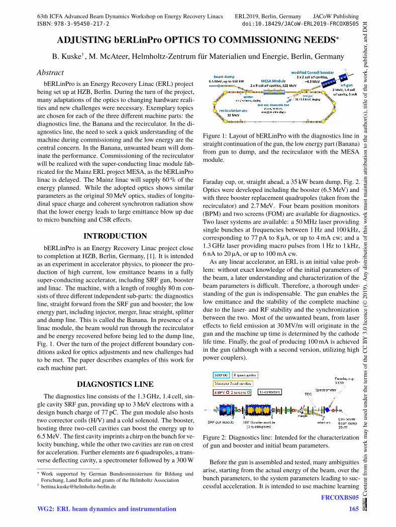
ADJUSTING bERLinPro OPTICS TO COMMISSIONING NEEDS∗
B. Kuske† , M. McAteer, Helmholtz-Zentrum für Materialien und Energie, Berlin, Germany
AbstractbERLinPro is an Energy Recovery Linac (ERL) project
being set up at HZB, Berlin. During the turn of the project,many adaptations of the optics to changing hardware reali-ties and new challenges were necessary. Exemplary topicsare chosen for each of the three different machine parts: thediagnostics line, the Banana and the recirculator. In the di-agnostics line, the need to seek a quick understanding of themachine during commissioning and the low energy are thecentral concern. In the Banana, unwanted beam will dom-inate the performance. Commissioning of the recirculatorwill be realized with the super-conducting linac module fab-ricated for the Mainz ERL project MESA, as the bERLinProlinac is delayed. The Mainz linac will supply 60% of theenergy planned. While the adopted optics shows similarparameters as the original 50MeV optics, studies of longitu-dinal space charge and coherent synchrotron radiation showthat the lower energy leads to large emittance blow up dueto micro bunching and CSR effects.
INTRODUCTIONbERLinPro is an Energy Recovery Linac project close
to completion at HZB, Berlin, Germany, [1]. It is intendedas an experiment in accelerator physics, to pioneer the pro-duction of high current, low emittance beams in a fullysuper-conducting accelerator, including SRF gun, boosterand linac. The machine, with a length of roughly 80m con-sists of three different independent sub-parts: the diagnosticsline, straight forward from the SRF gun and booster; the lowenergy part, including injector, merger, linac straight, splitterand dump line. This is called the Banana. In presence of alinac module, the beam would run through the recirculatorand be energy recovered before being led to the dump line,Fig. 1. Over the turn of the project different boundary con-ditions asked for optics adjustments and new challenges hadto be met. The paper describes examples of this work foreach machine part.
DIAGNOSTICS LINEThe diagnostics line consists of the 1.3GHz, 1.4 cell, sin-
gle cavity SRF gun, providing up to 3MeV electrons with adesign bunch charge of 77 pC. The gun module also hoststwo corrector coils (H/V) and a cold solenoid. The booster,hosting three two-cell cavities can boost the energy up to6.5MeV. The first cavity imprints a chirp on the bunch for ve-locity bunching, while the other two cavities are run on crestfor acceleration. Further elements are 6 quadrupoles, a trans-verse deflecting cavity, a spectrometer followed by a 300W
∗ Work supported by German Bundesministerium für Bildung undForschung, Land Berlin and grants of the Helmholtz Association
Figure 1: Layout of bERLinPro with the diagnostics line instraight continuation of the gun, the low energy part (Banana)from gun to dump, and the recirculator with the MESAmodule.
Faraday cup, or, straight ahead, a 35 kW beam dump, Fig. 2.Optics were developed including the booster (6.5MeV) andwith three booster replacement quadrupoles (taken from therecirculator) and 2.7MeV. Four beam position monitors(BPM) and two screens (FOM) are available for diagnostics.Two laser systems are available: a 50MHz laser providingsingle bunches at frequencies between 1Hz and 100 kHz,corresponding to 77 pA to 8 µA, or up to 4mA cw; and a1.3GHz laser providing macro pulses from 1Hz to 1 kHz,6 nA to 20 µA, or up to 100mA cw.As any linear accelerator, an ERL is an initial value prob-
lem: without exact knowledge of the initial parameters ofthe beam, a later understanding and characterization of thebeam parameters is difficult. Therefore, a thorough under-standing of the gun is indispensable. The gun enables thelow emittance and the stability of the complete machinedue to the laser- and RF stability and the synchronizationbetween the two. Most of the unwanted beam, from lasereffects to field emission at 30MV/m will originate in thegun and the machine up time is determined by the cathodelife time. Finally, the goal of producing 100mA is achievedin the gun (although with a second version, utilizing highpower couplers).
Figure 2: Diagnostics line: Intended for the characterizationof gun and booster and initial beam parameters.
Before the gun is assembled and tested, many ambiguitiesarise, starting from the actual energy of the beam, over thebunch parameters, to the system parameters leading to suc-cessful acceleration. It is intended to use machine learning
63th ICFA Advanced Beam Dynamics Workshop on Energy Recovery Linacs ERL2019, Berlin, Germany JACoW PublishingISBN: 978-3-95450-217-2 doi:10.18429/JACoW-ERL2019-FRCOXBS05
WG2: ERL beam dynamics and instrumentationFRCOXBS05
165
Cont
entf
rom
this
wor
km
aybe
used
unde
rthe
term
soft
heCC
BY3.
0lic
ence
(©20
19).
Any
distr
ibut
ion
ofth
isw
ork
mus
tmai
ntai
nat
tribu
tion
toth
eau
thor
(s),
title
ofth
ew
ork,
publ
isher
,and
DO
I
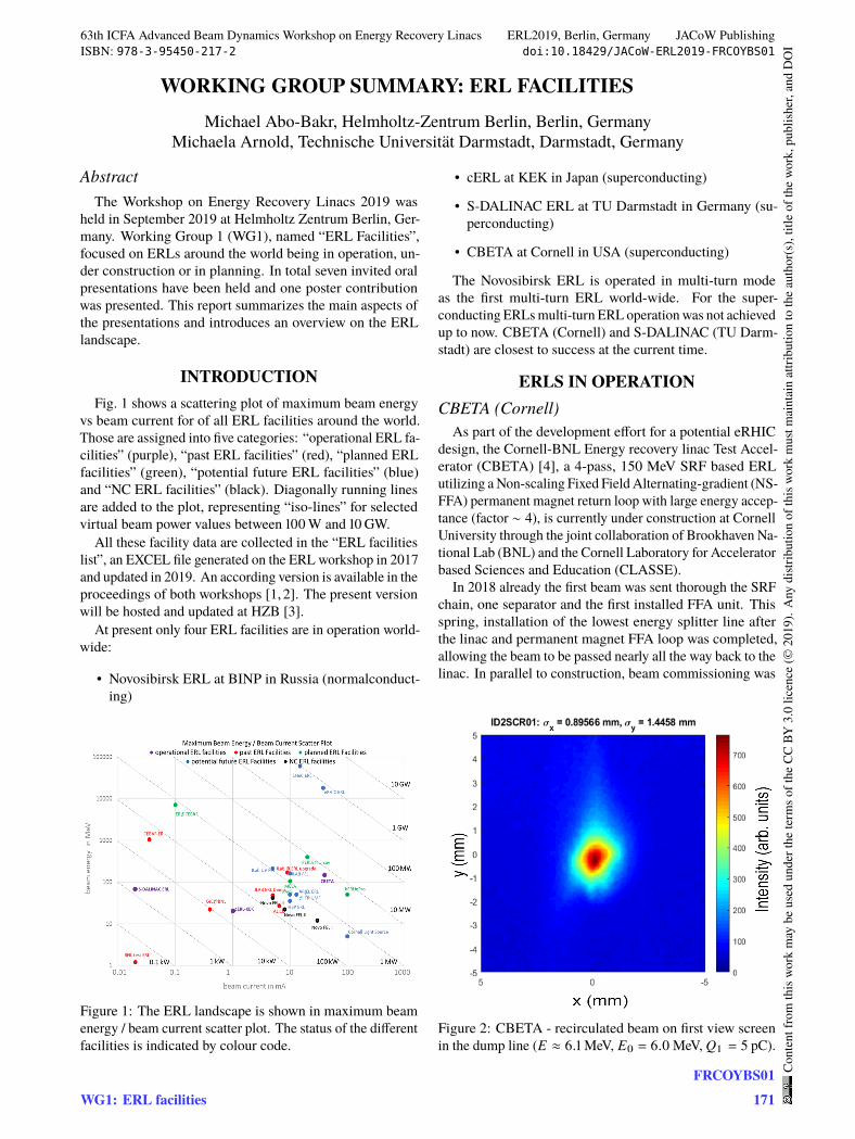
WORKING GROUP SUMMARY: ERL FACILITIESMichael Abo-Bakr, Helmholtz-Zentrum Berlin, Berlin, Germany
Michaela Arnold, Technische Universität Darmstadt, Darmstadt, Germany
AbstractThe Workshop on Energy Recovery Linacs 2019 was
held in September 2019 at Helmholtz Zentrum Berlin, Ger-many. Working Group 1 (WG1), named “ERL Facilities”,focused on ERLs around the world being in operation, un-der construction or in planning. In total seven invited oralpresentations have been held and one poster contributionwas presented. This report summarizes the main aspects ofthe presentations and introduces an overview on the ERLlandscape.
INTRODUCTIONFig. 1 shows a scattering plot of maximum beam energy
vs beam current for of all ERL facilities around the world.Those are assigned into five categories: “operational ERL fa-cilities” (purple), “past ERL facilities” (red), “planned ERLfacilities” (green), “potential future ERL facilities” (blue)and “NC ERL facilities” (black). Diagonally running linesare added to the plot, representing “iso-lines” for selectedvirtual beam power values between 100W and 10GW.
All these facility data are collected in the “ERL facilitieslist”, an EXCEL file generated on the ERL workshop in 2017and updated in 2019. An according version is available in theproceedings of both workshops [1, 2]. The present versionwill be hosted and updated at HZB [3].
At present only four ERL facilities are in operation world-wide:
• Novosibirsk ERL at BINP in Russia (normalconduct-ing)
Figure 1: The ERL landscape is shown in maximum beamenergy / beam current scatter plot. The status of the differentfacilities is indicated by colour code.
• cERL at KEK in Japan (superconducting)
• S-DALINAC ERL at TU Darmstadt in Germany (su-perconducting)
• CBETA at Cornell in USA (superconducting)
The Novosibirsk ERL is operated in multi-turn modeas the first multi-turn ERL world-wide. For the super-conducting ERLs multi-turn ERL operation was not achievedup to now. CBETA (Cornell) and S-DALINAC (TU Darm-stadt) are closest to success at the current time.
ERLS IN OPERATIONCBETA (Cornell)
As part of the development effort for a potential eRHICdesign, the Cornell-BNL Energy recovery linac Test Accel-erator (CBETA) [4], a 4-pass, 150 MeV SRF based ERLutilizing a Non-scaling Fixed Field Alternating-gradient (NS-FFA) permanent magnet return loop with large energy accep-tance (factor ∼ 4), is currently under construction at CornellUniversity through the joint collaboration of Brookhaven Na-tional Lab (BNL) and the Cornell Laboratory for Acceleratorbased Sciences and Education (CLASSE).
In 2018 already the first beam was sent thorough the SRFchain, one separator and the first installed FFA unit. Thisspring, installation of the lowest energy splitter line afterthe linac and permanent magnet FFA loop was completed,allowing the beam to be passed nearly all the way back to thelinac. In parallel to construction, beam commissioning was
Figure 2: CBETA - recirculated beam on first view screenin the dump line (𝐸 ≈ 6.1 MeV, 𝐸0 = 6.0 MeV, 𝑄𝑏 = 5 pC).
63th ICFA Advanced Beam Dynamics Workshop on Energy Recovery Linacs ERL2019, Berlin, Germany JACoW PublishingISBN: 978-3-95450-217-2 doi:10.18429/JACoW-ERL2019-FRCOYBS01
WG1: ERL facilitiesFRCOYBS01
171
Cont
entf
rom
this
wor
km
aybe
used
unde
rthe
term
soft
heCC
BY3.
0lic
ence
(©20
19).
Any
distr
ibut
ion
ofth
isw
ork
mus
tmai
ntai
nat
tribu
tion
toth
eau
thor
(s),
title
ofth
ew
ork,
publ
isher
,and
DO
I
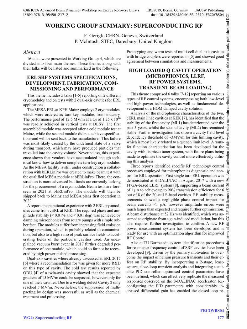
WORKING GROUP SUMMARY: SUPERCONDUCTING RF
F. Gerigk, CERN, Geneva, Switzerland P. McIntosh, STFC, Daresbury, United Kingdom
Abstract 16 talks were presented in Working Group 4, which are
divided into four main themes. These themes along with their talks will be listed and summarized in the following.
ERL SRF SYSTEMS SPECIFICATIONS, DEVELOPMENT, FABRICATION, COM-
MISSIONING AND PERFORMANCE This theme includes 5 talks [1-5] reporting on 2 different
cryomodules and on tests with 2 dual-axis cavities for ERL applications.
The MESA ERL at KPH Mainz employs 2 cryomodules, which were ordered as turn-key modules from industry. The performance goal of 12.5 MV/m at a Q0 of 1.25 x 10¹⁰ was readily achieved in vertical tests at DESY. The first assembled module was accepted after a cold module test at Mainz, while the second module did not achieve specifica-tions and will be sent back to the manufacturer. This failure was most likely caused by the undefined state of a valve during transport, which may have produced particles that travelled into the cavity volume. Nevertheless, this experi-ence shows that vendors have accumulated enough tech-nical know-how to deliver complete turn-key cryomodules. As the MESA facility is still under construction a collabo-ration with bERLinPro was created to make beam test with the qualified MESA module at bERLinPro. There, the con-struction is more advanced but funds are currently lacking for the procurement of a cryomodule. Beam tests are fore-seen in 2021 at bERLinPro. The module will then be shipped back to Mainz and MESA plans first operation in 2022.
A report on operational experience with 2 ERL cryomod-ules came from cERL at KEK. The required phase and am-plitude stability (< 0.01% and < 0.01 deg) was achieved by damping microphonics from rotary pumps with simple rub-ber feet. The modules suffer from increasing field emission during operation, which is probably related to contamina-tion, but also to a high ratio of peak surface fields to accel-erating fields of the particular cavities used. An unex-plained vacuum burst event in 2017 further degraded per-formance of one module, which could so far not be recov-ered by high power pulsed processing.
Dual-axis cavities where already discussed at ERL 2017 [6] where a recommendation for was given for more R&D on this type of cavity. The cold test results reported by ODU [4] of a twin-axis cavity showed that the expected gradient of 15 MV/m could be surpassed, however only for one of the 2 cavities. Due to a welding defect Cavity 2 only reached 5 MV/m. Nevertheless, the suppression of multi-pacting by design was successful as well as the chemical treatment and processing.
Prototyping and warm tests of multi-cell dual axis cavities with bridge couplers were reported in [5] and showed good agreement between simulations and measurements.
HIGH LOADED Q CAVITY OPERATION (MICROPHONICS, LLRF,
RF POWER SYSTEMS, TRANSIENT BEAM LOADING)
This theme comprised 6 talks [7-12] reporting on various types of RF control systems, encompassing both low-level and high-power technologies, as well as fundamental de-velopment of a HOM damped cavity solution.
Analysis of the microphonics characteristics of the two, cERL main linac cavities at KEK [7], has identified that the stability of the first cavity (ML1) has deteriorated over the past 5-years, whilst the second cavity (ML2) has remained stable. Further investigation has shown a cavity field-level dependency threshold of ~3MV/m for this limiting cavity, which is most likely related to a quench limit level. A trans-fer function characterisation has been developed for the cavity with its piezo tuner system, with future plans being made to optimise the cavity control more effectively utilis-ing this analysis.
Three reports identified specific RF technology control processes employed for microphonics diagnostic and con-trol for ERL operation. First single turn ERL operation was demonstrated at S-DALINAC in August 2017 with a new FPGA-based LLRF system [8], supporting a beam current of 1 μA to achieve up to 90% transmission efficiency for 6 out of 8 of the 20-cell S-band cavities. RF stability meas-urements showed a negligible phase control impact for beam currents <1 μA, however amplitude errors were much larger than expected and require further optimisation. A beam disturbance at 52 Hz was identified, which was as-sumed to originate from a gun-induced modulation, but this also requires further investigation to confirm. A new RF power measurement system has been developed and is ready for use with an optimization algorithm for improved RF Control.
Also at TU Darmstadt, system identification procedures for resonance frequency control of SRF cavities have been developed [9], driven by the primary motivation to over-come the impact of helium pressure transients and their ef-fect on RF stability. By incorporating a 2-stage, least-square, close-loop transient analysis and integrating a suit-able PID controller, optimised control parameters have been defined, which can effectively replicate the measured responses observed on the S-DALINAC accelerator. Re-configuring the PID parameters with considerably in-creased differential gain has enabled the closed-loop re-
63th ICFA Advanced Beam Dynamics Workshop on Energy Recovery Linacs ERL2019, Berlin, Germany JACoW PublishingISBN: 978-3-95450-217-2 doi:10.18429/JACoW-ERL2019-FRCOYBS04
WG4: Superconducting RFFRCOYBS04
177
Cont
entf
rom
this
wor
km
aybe
used
unde
rthe
term
soft
heCC
BY3.
0lic
ence
(©20
19).
Any
distr
ibut
ion
ofth
isw
ork
mus
tmai
ntai
nat
tribu
tion
toth
eau
thor
(s),
title
ofth
ew
ork,
publ
isher
,and
DO
I