ert 319 industrial waste treatment semester 1 2012/2013 huzairy hassan school of bioprocess...
TRANSCRIPT

ERT 319
Industrial Waste
TreatmentSemester 1 2012/2013
Huzairy HassanSchool of Bioprocess Engineering
UniMAP

Biological Treatment Processes of Industrial
Wastes

“Ability to calculate and compare the treatment methods for
particular wastes.&
Ability to design and evaluate various unit operations for waste treatments.”
Biological treatment / Unit operation

INTRODUCTIONObjectives of Biological Treatment:a) Transform (i.e., oxidize) dissolved and particulate
biodegradable constituent s by microorganisms into acceptable end products,
b) Capture and incorporate suspended and non-settleable colloidal solids into a biological floc or biofilm,
c) Transform and remove nutrients, such as nitrogen and phosphorus.. why???
d) In some cases, remove specific trace organic constituents and compounds.
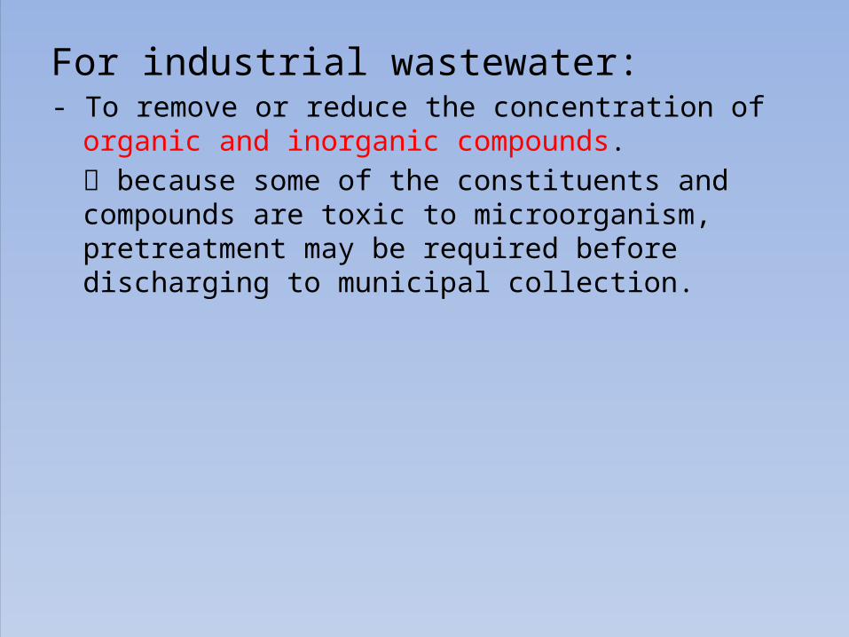
For industrial wastewater:- To remove or reduce the concentration of organic
and inorganic compounds. because some of the constituents and compounds are toxic to microorganism, pretreatment may be required before discharging to municipal collection.
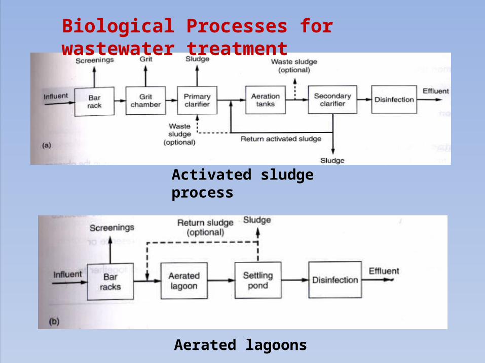
Activated sludge process
Aerated lagoons
Biological Processes for wastewater treatment

Trickling filters
Rotating biological contractors
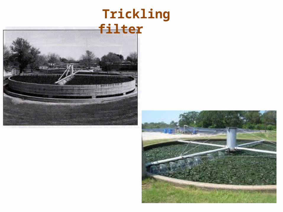
Trickling filter

Aerobic biological oxidation of organic matters
Nutrients for microbes to Converts organic matters to CO2 and H2O
Biomass produced
vi = stoichiometric coefficient
Composition & Classification of Microorganisms
** Revise the cell components, compositions, structure, DNA, RNA, microbial Growth & metabolism, C & N sources …


Aerobic, heterotrophic Aerobic, autotrophic
Anaerobic, heterotrophic
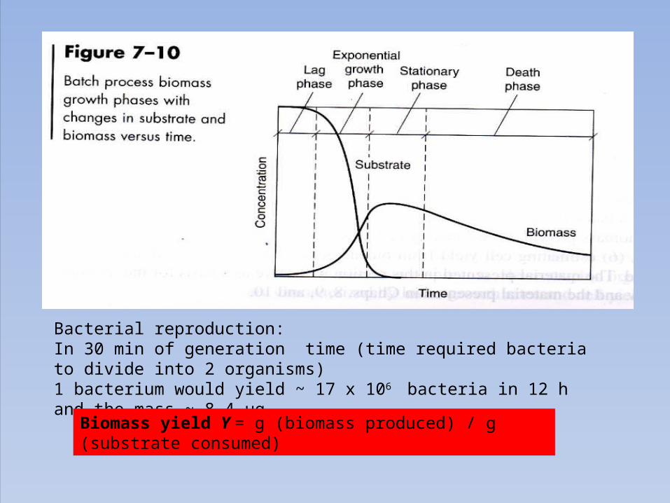
Bacterial reproduction: In 30 min of generation time (time required bacteria to divide into 2 organisms)1 bacterium would yield ~ 17 x 106 bacteria in 12 h and the mass ~ 8.4 µg
Biomass yield Y = g (biomass produced) / g (substrate consumed)
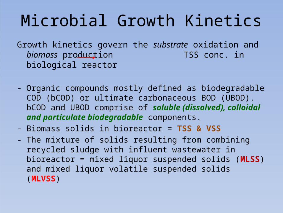
Microbial Growth KineticsGrowth kinetics govern the substrate oxidation and biomass
production TSS conc. in biological reactor
- Organic compounds mostly defined as biodegradable COD (bCOD) or ultimate carbonaceous BOD (UBOD). bCOD and UBOD comprise of soluble (dissolved), colloidal and particulate biodegradable components.
- Biomass solids in bioreactor = TSS & VSS- The mixture of solids resulting from combining recycled sludge
with influent wastewater in bioreactor = mixed liquor suspended solids (MLSS) and mixed liquor volatile suspended solids (MLVSS)

1) Rate of utilization of soluble substrates
(-ve : substrate decreases with time)
rsu = rate substrate conc. change due to utilization, g/m3.dk = max specific substrate utilization rate, g substrate/ g microbe . DKs = substrate conc. at one-half max substrate utilization rate g/m3

2) Rate of Biomass Growth with soluble substrate
3) Rate of oxygen uptake

4) Effects of temperature

5) Total volatile suspended solids & Active biomass
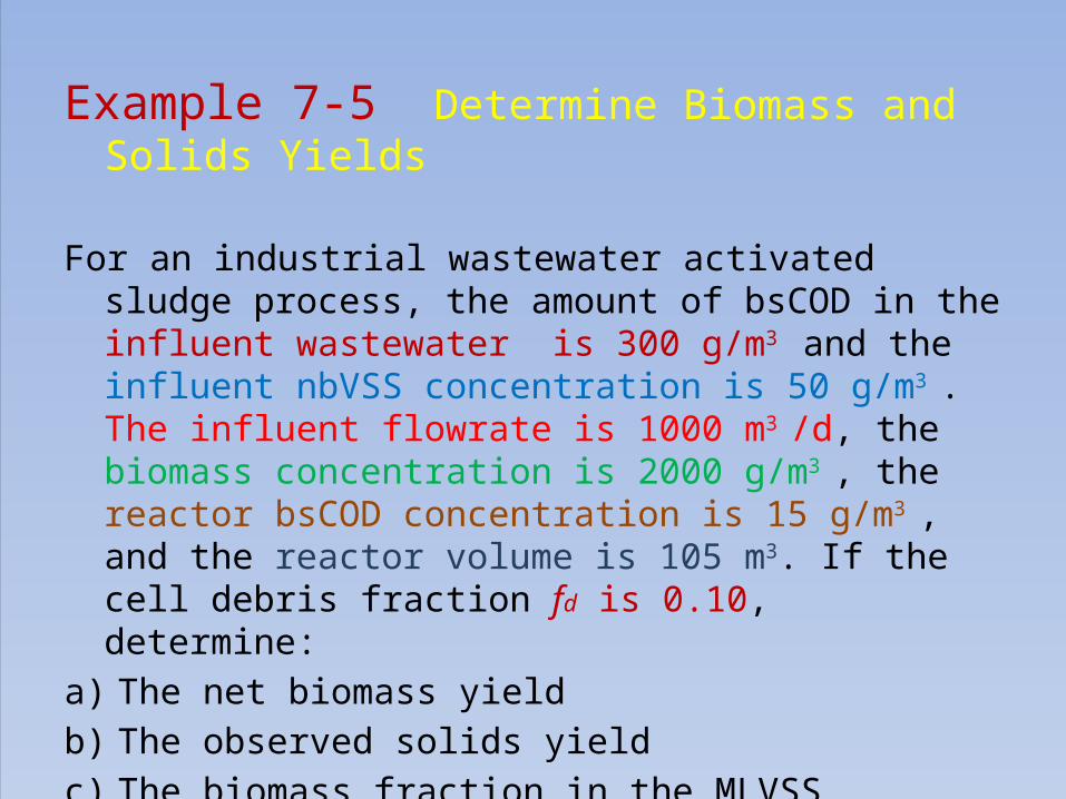
Example 7-5 Determine Biomass and Solids Yields
For an industrial wastewater activated sludge process, the amount of bsCOD in the influent wastewater is 300 g/m3 and the influent nbVSS concentration is 50 g/m3 . The influent flowrate is 1000 m3 /d, the biomass concentration is 2000 g/m3 , the reactor bsCOD concentration is 15 g/m3 , and the reactor volume is 105 m3. If the cell debris fraction fd is 0.10, determine:
a) The net biomass yieldb) The observed solids yieldc) The biomass fraction in the MLVSSd) Specific biomass growth rate, µ

Solution:??
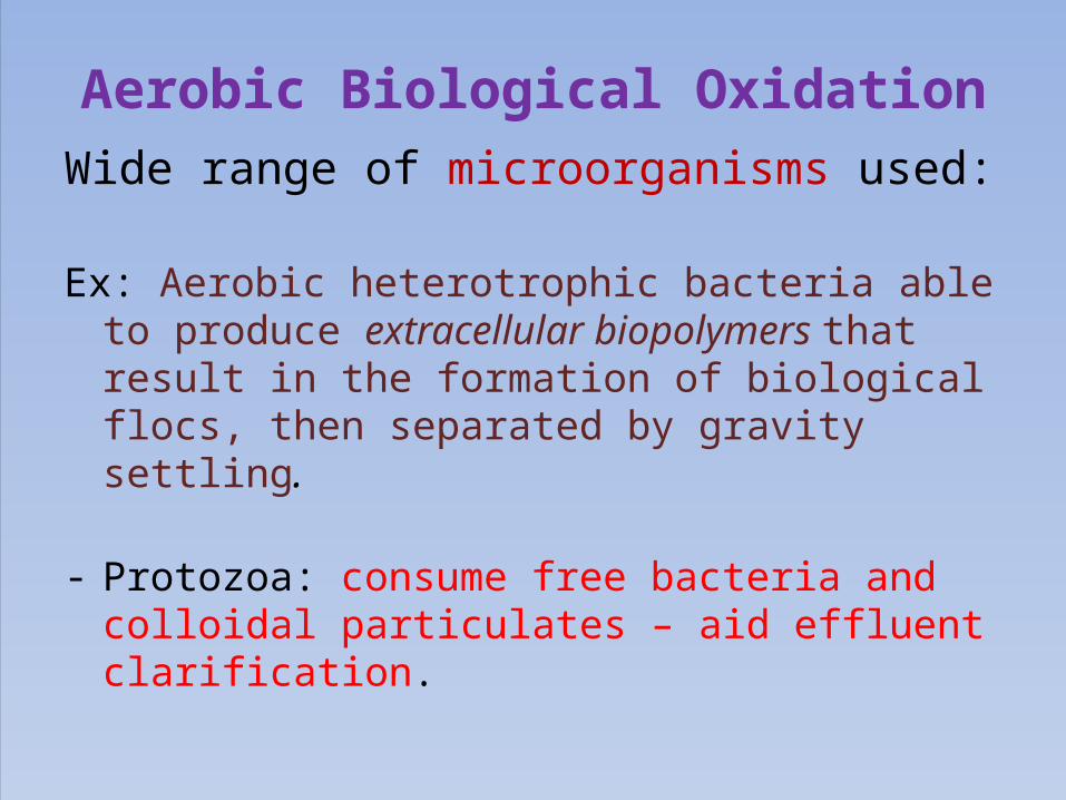
Aerobic Biological OxidationWide range of microorganisms used:
Ex: Aerobic heterotrophic bacteria able to produce extracellular biopolymers that result in the formation of biological flocs, then separated by gravity settling.
- Protozoa: consume free bacteria and colloidal particulates – aid effluent clarification.
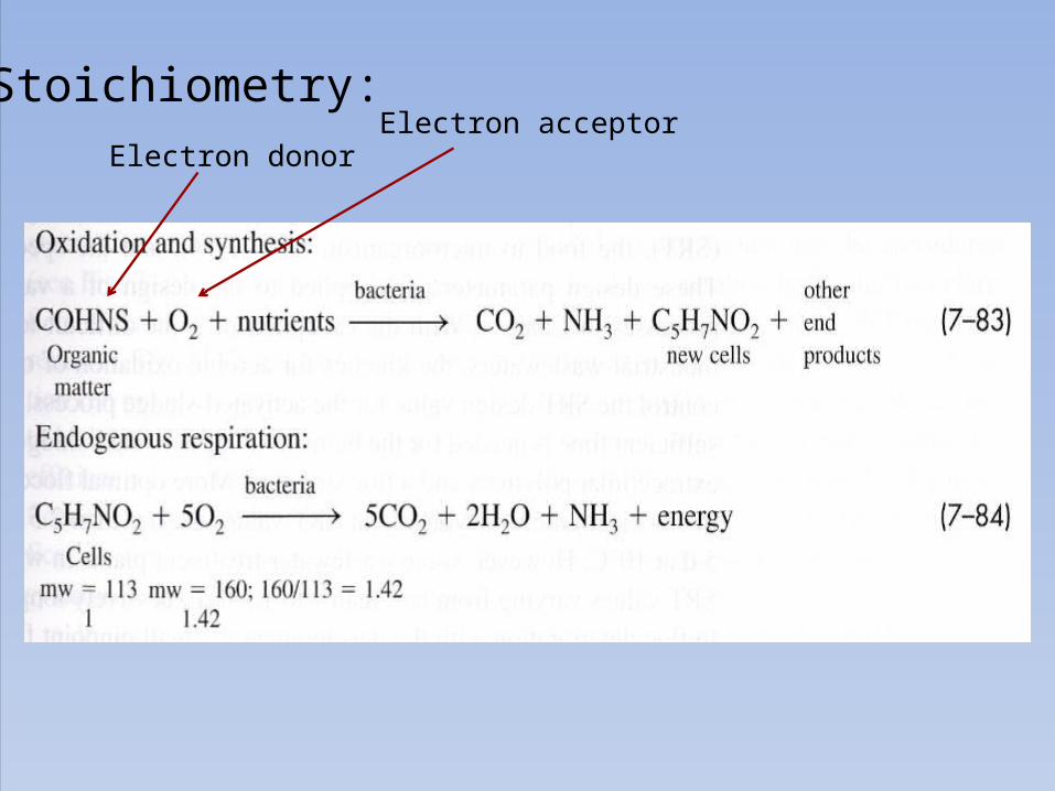
Stoichiometry:Electron donor
Electron acceptor

Biological NitrificationNitrification:2-step biological processes; • Ammonia (NH4-N) is oxidized to nitrite (NO2-N)• Nitrite is oxidized to nitrate (NO3-N)
Why??1) Ammonia & nitrite– associate DO conc. & fish toxicity2) Need for nitrogen removal:
– control eutrophication & water-reuse application

Nitroso-bacteria (Nitrosococcus, Nitrosospira, etc):2NH4+ + 3O2 2NO2- + 4H+ + 2H2O
Stoichiometry:
(Nitrobacter, Nitrococcus, Nitrospina, etc):
Nitrate:Safer form to aquatic lives

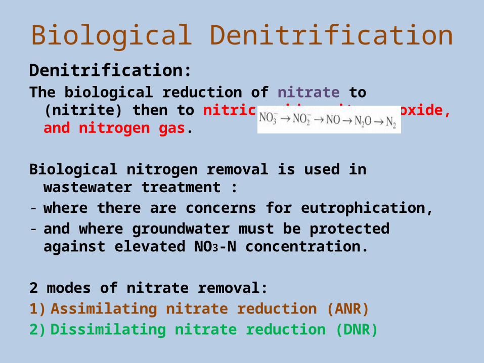
Biological DenitrificationDenitrification:The biological reduction of nitrate to (nitrite)
then to nitric oxide, nitrous oxide, and nitrogen gas.
Biological nitrogen removal is used in wastewater treatment :
- where there are concerns for eutrophication, - and where groundwater must be protected
against elevated NO3-N concentration.
2 modes of nitrate removal:1) Assimilating nitrate reduction (ANR)2) Dissimilating nitrate reduction (DNR)

• ANR involves the reduction of nitrate to ammonia for use in cell synthesis.Assimilation occurs when NH4-N is not available and is independent of DO concentration.
• DNR is coupled to the respiratory electron transport chain, and nitrate or nitrite is used as an electron acceptor for the oxidation of a variety of organic or inorganic electron donors.
• Microorganism for denitrification: both heterotrophic and autotrophic ( most are facultative aerobic organisms with the ability to use oxygen as well as nitrate or nitrite).
- Example: Achromobacter, Acinetobacter, Bacillus, Chromobacterium, Pseudomonas, Rhizobium, etc.

Biological Denitrification


In the first flow, nitrate produced in the aeration tank is recycled back to the anoxic tank (anaerobic). Because the organic substrate in the influent wastewater provides the e- donor for oxidation-reduction reactions using nitrate, the process is termed substrate denitrification. Or because the anoxic process precedes the aeration tank, the process is known as a preanoxic denitrification.
In the second process, denitrification occurs after nitrification and the e- donor source is from endogenous decay. BOD removal has occurred first, and is not available to drive the nitrate reduction reaction, and called postanoxic denitrification. It has much slower rate of reaction than preanoxic denitrification.Often, an exogenous carbon source such as methanol or acetate is added to postanoxic processes to provide sufficient BOD for nitrate reduction and to increase rate of denitrification.

Anaerobic Fermentation & Oxidation
Three basic steps in anaerobic oxidation of wastes:1) Hydrolysis:
particulate material is converted to soluble compounds that can then be hydrolyzed further to simple monomers that are used by bacteria that perform fermentation.
2) Fermentation (or acidogenesis):Amino acids, sugars, and some fatty acids are degraded further. The principle products are acetate, H2, CO2, and propionate and butyrate. Acetate, H2, CO2 precursors of methane formation (Methanogenesis)

3) Methanogenesis:Carried out by 2 groups of microorganisms (or Methanogens):
a) Aceticlastic methanogens– split acetate into methane and CO2
CH3COOH CH4 + CO2
b) Hydrogen-utilizing methanogens- use H2 as electron donor and CO2 as the
electron acceptor to produce methane
Nuisance organisms in anaerobic fermentation- When the wastewater contains significant concentrations of sulfate - Sulfate-reducing bacteria can reduce sulfate to sulfide (toxic to methanogenic bacteria)- Then, how to solve??
How??
Environmental factors:- Anaerobic processes are sensitive to pH & inhibitory
substances (ex: NH3, H2S, etc.)- pH near neutral preferred ;- pH below 6.8 methanogenic activity is inhibited- Due to about 30-35 % CO2 (high) produced in anaerobic
process, high alkalinity is needed to neutralize pH- Range of alkalinity, i.e., 3000-5000 mg/L as CaCO3 is often
found.
In industrial wastewater applications which mainly contain carbohydrates, it is necessary to
add alkalinity for pH control.
Types of Biological Process for Wastewater Treatment
Suspended Growth Process
Attached Growth Process (Biofilm)

SUSPENDED GROWTH BIOLOGICAL
TREATMENT PROCESS

Suspended Growth Processes (SGP) Microbes are maintained in liquid suspension by mixing
methods Most common SGP: Activated-sludge process (ASP)
- ASP uses activated mass of microbes capable of stabilizing a waste under aerobic conditions - mix wastewater with microbial suspension •MLSS•MLVSS
MLSS flows to clarifier (where microbial suspension is settled and thickened) “Activated sludge (AS)”
AS is returned to aeration tank to continue biodegradation of organic material

Activated Sludge Process
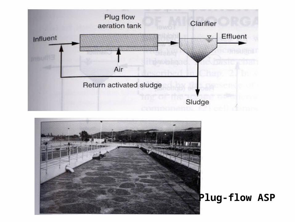
Plug-flow ASP

Complete mix ASP
Selection & Design ASP
Aeration
Systems
Aeration Tanks
Solids Separat
ion
Solid Separati
on Facilities

Selection & Design for Activated Sludge Processes
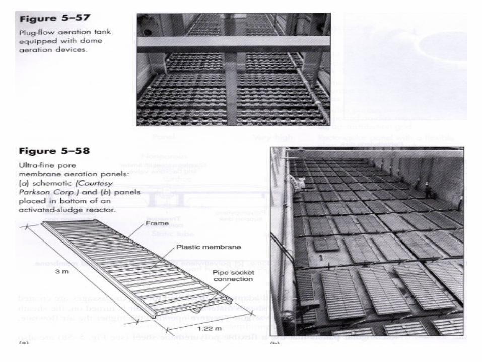
1) Aeration SystemAeration system must be adequate to:a) Satisfy the bCOD of the wastesb) Satisfy the endogenous respiration by the biomassc) Satisfy the O2 demand for nitrificationd) Provide adequate mixinge) Maintain minimum dissolved O2 conc. throughout the tank
Can design /estimate the actual air requirements for diffused air aeration or installed power of mechanical surface aerators.


2) Aeration Tanks and Appurtenances (support facilities)
a) Aeration Tanks- Usually constructed of reinforced concrete and left open to atmosphere- Capacity:
• capacity range of 0.22 to 0.44 m3 /s at least 2 tanks needed• capacity range of 0.44 to 2.2 m3 /s at least 4 tanks needed• capacity range over 2.2 m3 /s at least 6 tanks or more
- Depth of wastewater in the tanks: between 4.5 and 7.5 m- Freeboard: 0.3 – 0.6 m above waterline- Width-to-depth ratio of the tanks (spiral-flow mixing): 1:1, 2.2:1 or
1.5:1 (most common)

b) Flow distribution- from multiple units of primary sedimentation tanks & aeration tanks to ASP tanks- methods of splitting or controlling the flow rate, for ex: splitter boxes equipped with weirs or control valves or aeration tanks influent control gates. - Hydraulic balancing of flow by equalizing the headloss from the primary sedimentation basins.

c) Froth control systems- Foaming- when the aerated wastewater which contains soap, detergents & other surfactants- Foaming action produces froth that contains sludge solids, grease, and wastewater bacteria.- Wind may lift & blow the froth contaminate whatever it touches, slippery, and difficult to remove once it has dried.- solutions: remove froth by spraying clear water or screened effluent through nozzles or,adding antifoaming chemical additives in spray water

d) Nocardia Foam Control- Nocardia foam is a thick layer of brown biological foams that forms on the top of aeration tanks and clarifiers. - Nocardia organisms grows, tend to trap air bubbles float to the surface and accumulate as scum (dirty foam) - Controlled by:
i) Spraying chlorine solution directly into foam layer in some cases, spray nozzles installed within a hood located across the width of plug flow aeration tanks may not be effective, because it can cause floc
breakup & inhibit BOD removal and nitrification
ii) Addition of cationic polymer

3) Solids Separation Facilities
a) AS settling tank types- circular or rectangular- circular tank:
Diameter = 2 – 60 m (or 10 -40 m)tank radius > 5 X sidewater depth
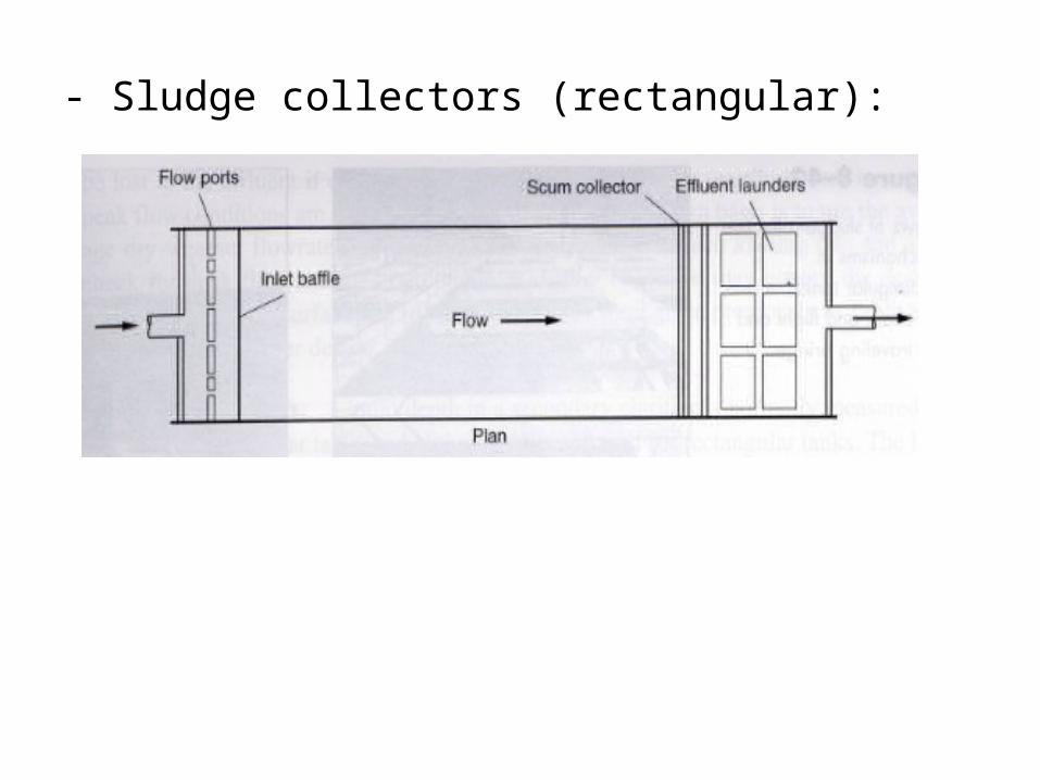
- Sludge collectors (rectangular):

Suspended Growth Aerated Lagoons• Suspended growth aerated lagoons (SGAL) are relatively shallow
earthen basins varying in depth from 2 – 5 m, provided with mechanical aerators on floats or fixed platforms.
• Mechanical aerators: - to provide oxygen for biological treatment of wastewater , - to keep the biological solids in suspension.• SGAL are operated on a flow-through basis or with solids recycle.
• Types of SGAL:1. Facultative partially mixed2. Aerobic flow through with partial mixing3. Aerobic with solids recycle and nominal complete mixing

Process Design Considerations for flow-through lagoons:
1) BOD Removal2) Effluent characteristics3) Temperature effects4) Oxygen requirement5) Energy requirement for mixing6) Solids separation.

Example 8-14 Design of a Flow-through Aerated LagoonDesign a flow-through aerated lagoon to treat a wastewater flow of 3800 m3/d,
including the number of surface aerators and their kilowatt rating. The treated liquid is to be held in a settling basin (lagoon) with a 2-d detention time before being discharged. Assume that the following conditions and requirements apply:
1. Influent TSS = 200 g/m3 (influent TSS are not degraded biologically)2. Influent sBOD = 200 g/m3
3. Effluent sBOD = 30 g/m3
4. Effluent suspended solids after settling = 20 g/m3
5. Kinetic coefficients: Y = 0.65 g/g, Ks = 100 g/m3, k = 6.0 g/g.d, kd = 0.07 g/g.d for T = 20 to 25 ⁰C
6. Total solids produced are equal to computed volatile suspended solids divided by 0.85
7. First-order observed soluble BOD removal-rate constant k20 = 2.5 d-1 at 20 ⁰C.

8. Summer air temperature = 30 ⁰C9. Winter air temperature during coldest month = 6 ⁰C10. Wastewater temperature during winter = 16 ⁰C11. Wastewater temperature during summer = 22 ⁰C12. Temperature coefficient, θ = 1.0613. Aeration constants: α = 0.85, β = 1.014. Aerator oxygen transfer rate = 1.8 kg O2/kWh
15. Elevation = 500 m16. Oxygen concentration to be maintained in liquid = 1.5 g/m3 17. Lagoon depth = 3.3 m18. Design SRT = 5d19. Power required for mixing = 8 kW/103/m3

ATTACHED GROWTH BIOLOGICAL TREATMENT
PROCESS
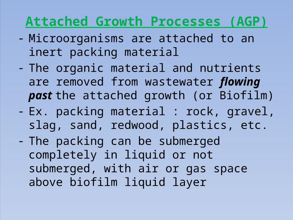
Attached Growth Processes (AGP)- Microorganisms are attached to an inert packing
material- The organic material and nutrients are removed from
wastewater flowing past the attached growth (or Biofilm)
- Ex. packing material : rock, gravel, slag, sand, redwood, plastics, etc.
- The packing can be submerged completely in liquid or not submerged, with air or gas space above biofilm liquid layer

- Most common: Trickling filter – wastewater is distributed over the top area of
a vessel containing non-submerged packing material
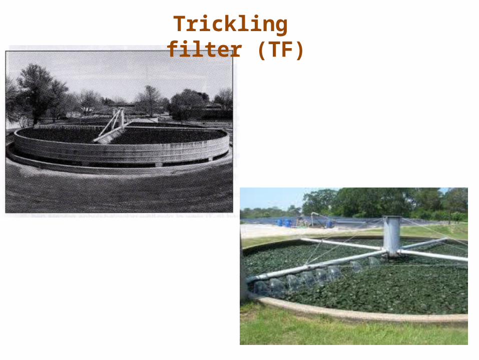
Trickling filter (TF)


Process flow in Trickling FilterThe wastewater is applied over the bed of supporting media (rocks, stones, ceramic
pieces, slag, etc) by rotating arms.The effluent is collected in the secondary clarifier, to separate washed out biomass
solids before final disposal.
As the wastewater trickles through the filter media, growth of microorganism takes place on the surface of packing material known as bio-film or slime layer.
When the wastewater passes over this film, contact between substrates or food (waste) and microorganism is established, thus, the waste is decomposed aerobically by the attached biomass. (Facultative bacteria –attach in trickling filters, decompose the organic material in the wastewater along with aerobic and anaerobic bacteria).
Then, a stage comes when anaerobic conditions are developed nearer to the media surface and the microorganisms cannot remain attached or fixed to the media.
the slime layer then eventually peels off (or washed out) and removed from the filter along with (next) flow.
- the washed out of slime layer is called sloughing.
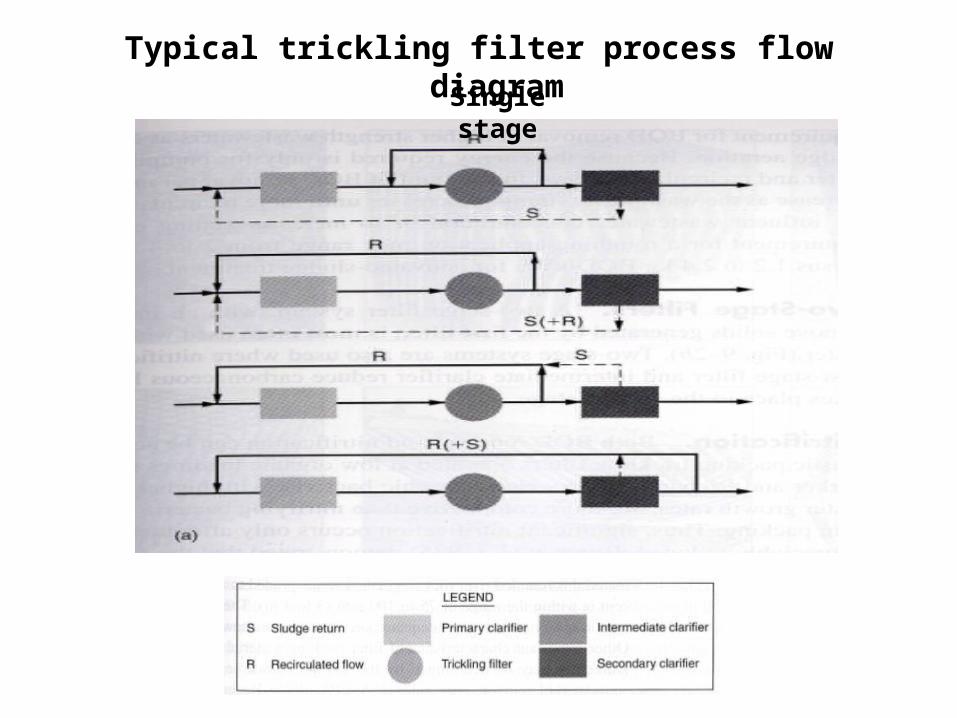
Typical trickling filter process flow diagramSingle stage
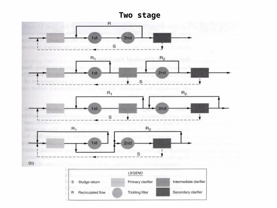
Two stage


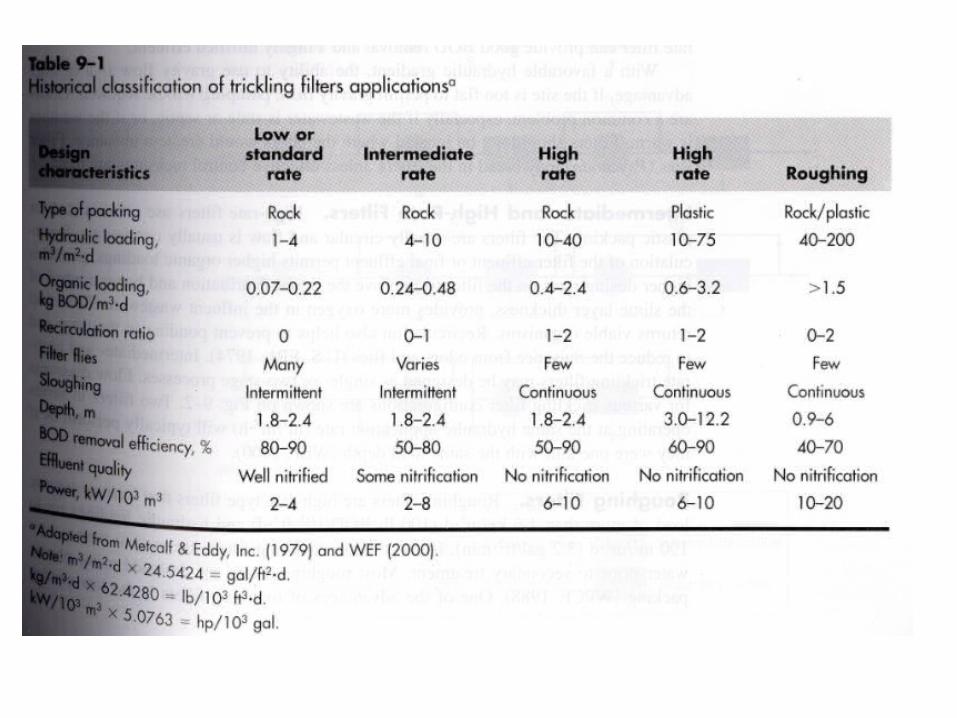
Design Criteria of Trickling Filtera) Dosing rate• Dosing rate in Trickling Filter (TF) is the depth of
liquid discharged on top of packing for each pass of the distributor.
• For higher distributor rotational speeds, the dosing rate is lower.
• With 2 or 4 arms, TF is dosed every 10 – 60s. • Investigations show that reducing distributor speed
results in better filter performance improve BOD removal, reduce Psychoda & Anisopus fly population, biofilm thickness, and odors.

b) Loading criteria Quantifying biomass / biological & hydrodynamic properties in
TF are not possible. Why ??
Attached growth is not uniformly distributed in TF The biofilm thickness can vary Biofilm solids concentration may range from 40 to 100 g/L The liquid does not uniformly flow over the entire packing
surface area. Hence, use to find broader parameters such as: volumetric
organic loading, unit area loadings, and hydraulic application rates used as design / operating parameters to relate treatment efficiency

Higher Dosing Rate
Larger water volume applied / revolution
Greater wetting efficiency
Greater agitation – causes more solids
to flush out
Thinner biofilm – increase surface area & more aerobic
biofilm
Wash away fly eggs

ROTATING BIOLOGICAL CONTACTORS (RBC)
RBC consists of series of closely spaced circular disks (polystyrene or polyvinyl chloride) submerged (typically 40%) in wastewater and rotated through it.
The dicks are attached to a horizontal shaft.
The assembly of shaft, disks and rotating equipments is called one module. Normally in industrial waste treatment, more than 3 modules arranged in series or parallel.


Removal Mechanism of RBCAs the shaft rotates, the surfaces of rotating disks alternately come
in contact with the microorganisms and organic content of wastewater and atmosphere.
During the rotation, the microbes get attached to the disks, and O2 from atmosphere is transferred to the wastewater to maintain aerobic condition.
The microbes attached to the disks surface grow in the form of biological film and consume organic content in the wastes.
After some times, as the bio-films thickens, an anaerobic condition develops nearer to the disks surface , then the slime layer gets washed out (sloughing) by incoming wastewater flow.
the sloughed bio-films is ultimately removed in the secondary clarifier before final disposal of treated effluent.
………>> Similar mechanism to Trickling filter <<…………


Example 9-7 Design of staged RBC for BOD RemovalGiven the following design conditions, develop a process
design for a staged RBC system
Parameter Unit Primary Effluent Target EffluentFlowrate
BOD
sBOD
TSS
m3/d
g/m3
g/m3
g/m3
4000
140
90
70
20
10
20

THANK YOU