es 282 002 - v1.1.1 - telecommunications and internet ... es 282 002 v1.1.1 (2006-03) etsi standard...
TRANSCRIPT
ETSI ES 282 002 V1.1.1 (2006-03)
ETSI Standard
Telecommunications and Internet converged Services andProtocols for Advanced Networking (TISPAN);
PSTN/ISDN Emulation Sub-system (PES);Functional architecture

ETSI
ETSI ES 282 002 V1.1.1 (2006-03) 2
Reference DES/TISPAN-02019-NGN-R1
Keywords ISDN, PSTN
ETSI
650 Route des Lucioles F-06921 Sophia Antipolis Cedex - FRANCE
Tel.: +33 4 92 94 42 00 Fax: +33 4 93 65 47 16
Siret N° 348 623 562 00017 - NAF 742 C
Association à but non lucratif enregistrée à la Sous-Préfecture de Grasse (06) N° 7803/88
Important notice
Individual copies of the present document can be downloaded from: http://www.etsi.org
The present document may be made available in more than one electronic version or in print. In any case of existing or perceived difference in contents between such versions, the reference version is the Portable Document Format (PDF).
In case of dispute, the reference shall be the printing on ETSI printers of the PDF version kept on a specific network drive within ETSI Secretariat.
Users of the present document should be aware that the document may be subject to revision or change of status. Information on the current status of this and other ETSI documents is available at
http://portal.etsi.org/tb/status/status.asp
If you find errors in the present document, please send your comment to one of the following services: http://portal.etsi.org/chaircor/ETSI_support.asp
Copyright Notification
No part may be reproduced except as authorized by written permission. The copyright and the foregoing restriction extend to reproduction in all media.
© European Telecommunications Standards Institute 2006.
All rights reserved.
DECTTM, PLUGTESTSTM and UMTSTM are Trade Marks of ETSI registered for the benefit of its Members. TIPHONTM and the TIPHON logo are Trade Marks currently being registered by ETSI for the benefit of its Members. 3GPPTM is a Trade Mark of ETSI registered for the benefit of its Members and of the 3GPP Organizational Partners.
ETSI
ETSI ES 282 002 V1.1.1 (2006-03) 3
Contents
Intellectual Property Rights ................................................................................................................................5
Foreword.............................................................................................................................................................5
Introduction ........................................................................................................................................................5
1 Scope ........................................................................................................................................................6
2 References ................................................................................................................................................6
3 Definitions and abbreviations...................................................................................................................6 3.1 Definitions..........................................................................................................................................................6 3.2 Abbreviations .....................................................................................................................................................7
4 Overall NGN context................................................................................................................................7 4.1 PSTN/ISDN emulation as part of NGN ...........................................................................................................10 4.2 Common reference points ................................................................................................................................10 4.2.1 Transport.....................................................................................................................................................10 4.2.2 Resource allocation.....................................................................................................................................10 4.2.3 Network access sub-system ........................................................................................................................10 4.2.4 Customer location .......................................................................................................................................11 4.2.5 Media server ...............................................................................................................................................11 4.2.6 Presence ......................................................................................................................................................12 4.2.7 Messaging ...................................................................................................................................................12 4.2.8 Application servers .....................................................................................................................................12 4.2.9 Customer data .............................................................................................................................................12
5 Overall architecture ................................................................................................................................12 5.1 Functional entities ............................................................................................................................................12 5.2 Reference points ...............................................................................................................................................14 5.2.1 Between AGF (analogue) and AGCF (a)....................................................................................................15 5.2.2 Between AGF (BRI) and AGCF (b) ...........................................................................................................15 5.2.3 Between AGF (PRI) and AGCF (c)............................................................................................................15 5.2.4 Between MGF (Trunk) and TGCF (d)........................................................................................................15 5.2.5 Between SGCF and PSTN (STP) (e) ..........................................................................................................15 5.2.6 Between Call Server/Topology Hiding Function and other NGNs (f)........................................................15 5.2.7 Between PSTN/ISDN services and RACS (g) (Gq') ..................................................................................16 5.2.8 Between Customer data and NASS for physical Location information (h) ................................................16 5.2.9 Between PSTN/ISDN Emulation Sub-system and IMS application servers (i)..........................................16 5.2.10 Between Customer Data and Application Servers (j) .................................................................................16 5.2.11 Between call servers and presence servers (k) ............................................................................................16 5.2.12 Between services and customer location function (m) ...............................................................................16 5.3 Guidance on protocol issues.............................................................................................................................17 5.3.1 Guidance for Internal protocols ..................................................................................................................17 5.4 PSTN/ISDN emulation using IMS ...................................................................................................................17
6 Resource allocation ................................................................................................................................17 6.1 Resource allocation architecture.......................................................................................................................18 6.2 Modes of operation...........................................................................................................................................19 6.2.1 One and two phase commit.........................................................................................................................19 6.2.2 Single and double requesters ......................................................................................................................19 6.2.3 Hard and soft State for Recovery................................................................................................................20 6.2.4 Transmission faults .....................................................................................................................................20 6.2.5 Overload .....................................................................................................................................................20 6.2.6 Gate control ................................................................................................................................................21 6.2.7 Bearer capabilities.......................................................................................................................................21 6.2.8 Priority ........................................................................................................................................................21 6.2.9 Derived PSTN/ISDN calls ..........................................................................................................................22 6.2.10 Three and more party calls..........................................................................................................................22 6.3 Functional entity model....................................................................................................................................23
ETSI
ETSI ES 282 002 V1.1.1 (2006-03) 4
6.3.1 Description of Model ..................................................................................................................................23 6.3.2 Description of functional entities................................................................................................................23 6.3.2.1 AF .........................................................................................................................................................23 6.3.2.2 SPDF.....................................................................................................................................................23 6.3.2.3 RACF ....................................................................................................................................................23 6.4 Information flows .............................................................................................................................................23 6.4.1 Definition of information flows across ra....................................................................................................24 6.5 Timers ..............................................................................................................................................................24 6.5.1 SPDFRespTimer .........................................................................................................................................25 6.6 Non-functional requirements............................................................................................................................25 6.7 Protocol requirements.......................................................................................................................................25
7 Network attachment ...............................................................................................................................25 7.1 General .............................................................................................................................................................25
8 Transport ................................................................................................................................................26
9 Common functions .................................................................................................................................27 9.1 Routing data .....................................................................................................................................................27 9.1.1 ENUM ........................................................................................................................................................27 9.1.1.1 Outline requirements.............................................................................................................................27 9.1.1.2 Information flows..................................................................................................................................28 9.2 IMS application servers....................................................................................................................................28 9.3 IN servers .........................................................................................................................................................29 9.4 Master data .......................................................................................................................................................29 9.5 IBCF.................................................................................................................................................................29
10 User signalling........................................................................................................................................29 10.1 Z and S/T reference points ...............................................................................................................................29 10.2 Derived voice interfaces ...................................................................................................................................30 10.2.1 PSTN ..........................................................................................................................................................30 10.2.2 ISDN...........................................................................................................................................................30
11 Network signalling .................................................................................................................................31
12 User management ...................................................................................................................................32 12.1 Customer data co-ordination ............................................................................................................................32 12.2 Customer data in routing database ...................................................................................................................32 12.3 Customer data in call server .............................................................................................................................32 12.4 Customer data in IMS application servers........................................................................................................33 12.5 Customer data seen by external systems including UPSF................................................................................33
Annex A (informative): PES interconnection scenarios......................................................................34
Annex B (informative): Bibliography...................................................................................................35
History ..............................................................................................................................................................36
ETSI
ETSI ES 282 002 V1.1.1 (2006-03) 5
Intellectual Property Rights IPRs essential or potentially essential to the present document may have been declared to ETSI. The information pertaining to these essential IPRs, if any, is publicly available for ETSI members and non-members, and can be found in ETSI SR 000 314: "Intellectual Property Rights (IPRs); Essential, or potentially Essential, IPRs notified to ETSI in respect of ETSI standards", which is available from the ETSI Secretariat. Latest updates are available on the ETSI Web server (http://webapp.etsi.org/IPR/home.asp).
Pursuant to the ETSI IPR Policy, no investigation, including IPR searches, has been carried out by ETSI. No guarantee can be given as to the existence of other IPRs not referenced in ETSI SR 000 314 (or the updates on the ETSI Web server) which are, or may be, or may become, essential to the present document.
Foreword This ETSI Standard (ES) has been produced by ETSI Technical Committee Telecommunications and Internet converged Services and Protocols for Advanced Networking (TISPAN).
Introduction The present document describes the emulation of a PSTN/ISDN within the context of an NGN. It is intended to allow designers and specifiers of an NGN to understand how to share the services of an NGN amongst many service types of which just one is the emulation of a PSTN.
It is not intended that the specification of the internal structure of an NGN emulation of the PSTN/ISDN be constrained by the present document and in particular it is expected that it may be different from the internal architecture of the other sub-systems within the NGN.

ETSI
ETSI ES 282 002 V1.1.1 (2006-03) 6
1 Scope The present document is part of NGN Release 1. The purpose of the present document is to describe the functional architecture for PSTN/ISDN Emulation as part of the NGN.
2 References The following documents contain provisions which, through reference in this text, constitute provisions of the present document.
• References are either specific (identified by date of publication and/or edition number or version number) or non-specific.
• For a specific reference, subsequent revisions do not apply.
• For a non-specific reference, the latest version applies.
Referenced documents which are not found to be publicly available in the expected location might be found at http://docbox.etsi.org/Reference.
[1] ETSI TS 124 229: "Digital cellular telecommunications system (Phase 2+); Universal Mobile Telecommunications System (UMTS); Internet Protocol (IP) multimedia call control protocol based on Session Initiation Protocol (SIP) and Session Description Protocol (SDP); Stage 3 (3GPP TS 24.229 version 7.2.0 Release 7)".
[2] ETSI TS 123 141: "Universal Mobile Telecommunications System (UMTS); Presence service; Architecture and functional description; Stage 2 (3GPP TS 23.141 version 6.9.0 Release 6)".
[3] ETSI ES 282 003: "Telecommunications and Internet converged Services and Protocols for Advanced Networking (TISPAN); Resource and Admission Control Sub-system (RACS); Functional Architecture".
[4] MSF Document MSF-IA-NRCP.001-FINAL: Implementation Agreement for Network Resource Control Protocol (NRCP) (http://www.msforum.org/techinfo/approved/MSF-IA-NRCP.001-FINAL.pdf).
[5] ETSI ES 283 002: "Telecommunications and Internet converged Services and Protocols for Advanced Networking (TISPAN); PSTN/ISDN Emulation Subsystem (PES); NGN Release 1 H.248 Profile for controlling Access and Residential Gateways".
[6] ETSI TR 183 014: "Telecommunications and Internet converged Services and Protocols for Advanced Networking (TISPAN); PSTN/ISDN Emulation; Development and Verification of PSTN/ISDN Emulation".
[7] ITU-T Recommendation E.164: "The international public telecommunication numbering plan".
3 Definitions and abbreviations
3.1 Definitions For the purposes of the present document, the following terms and definitions apply:
derived voice service: presentation of voice service using an interface that is derived from a broadband link such as DSL
NOTE: There is not a Network Termination Point (NTP) of the traditional kind since the NTP is carrying packets, instead the service presents itself at a termination on equipment in the customer's premises.
ETSI
ETSI ES 282 002 V1.1.1 (2006-03) 7
3.2 Abbreviations For the purposes of the present document, the following abbreviations apply:
AF Application Function AGCF Analogue Gateway Control Function AGF Analogue Gateway Function A-RACF Access-Resource and Admission Control Function AS Application Server BRI Basic Rate Interface CCBS Call Completion on Busy Service CSCF Call Server Control Function DSL Digital Subscriber Line GRE Generic Routing Encapsulation IBCF Interconnect Border Control Function I-BGF Interconnection Border Gateway Function I-CSCF Interrogating Call Server Control Function IMS IP Multimedia Sub-system IP Internet Protocol IPSec IP Security ISDN Integrated Service Digital Network ISUP ISDN User Part (of Signalling System 7) M2UA MTP2 User Adaptation Layer M3UA MTP3 User Adaptation Layer MGCP Media Gateway Control Protocol MGF Media Gateway Function MMS Multimedia Messaging Service MSF Multiservice Switching Forum MTP Message Transfer (Part of Signalling System 7) MWI Message Waiting Indication NASS Network Attachment Sub-System NGN Next Generation Network NNI Network-Network Interface NTE Network Termination Equipment NTP Network Termination Point PES PSTN/ISDN Emulation Sub-system PRI Primary Rate Interface PSTN Public Switched Telephone Network RACS Resource and Admission Control Sub-system RTCP Real Time Control Protocol RTP Real Time Protocol SCCP Signalling Connection Control Part (of Signalling System 7) S-CSCF Serving Call Server Control Function SGCF Signalling Gateway Control Function SIP Session Initiation Protocol SipURI Session initiation protocol Uniform Resource Identifier SMS Short Message Service SPDF Service-based Policy Decision Function TASI Time Assigned Speech Interpolation TDM Time Division Multiplexing TelURI Telephony Uniform Resource Identifier TGCF Trunk Gateway Control Function THF Topology Hiding Function TIPHON ETSI Project: Telecommunications and Internet Protocol Harmonization Over Networks VPN Virtual Private Network
4 Overall NGN context The present document will describe how the sub-system fits within the overall structure of NGN and what specific behaviour and functions are needed for the emulation sub-system to fulfil its goals.
ETSI
ETSI ES 282 002 V1.1.1 (2006-03) 8
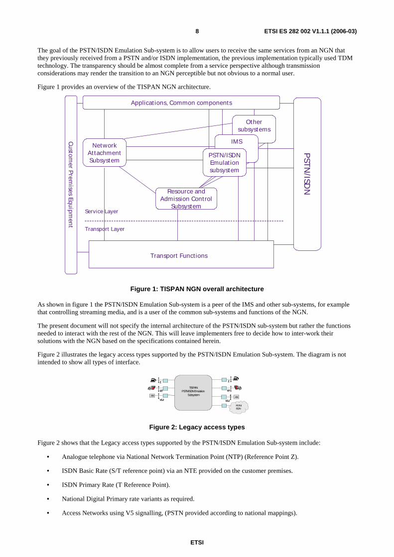
The goal of the PSTN/ISDN Emulation Sub-system is to allow users to receive the same services from an NGN that they previously received from a PSTN and/or ISDN implementation, the previous implementation typically used TDM technology. The transparency should be almost complete from a service perspective although transmission considerations may render the transition to an NGN perceptible but not obvious to a normal user.
Figure 1 provides an overview of the TISPAN NGN architecture.
Resource and Admission Control
Subsystem
PST
N/ISD
N
Other subsystems
IMS
PSTN/ISDN Emulat ionsubsystem
Applicat ions, Common components
Cu
stomer P
remises Equ
ipmen
t
Service Layer
Transport Layer
Transport Functions
Network At tachment Subsystem
Figure 1: TISPAN NGN overall architecture
As shown in figure 1 the PSTN/ISDN Emulation Sub-system is a peer of the IMS and other sub-systems, for example that controlling streaming media, and is a user of the common sub-systems and functions of the NGN.
The present document will not specify the internal architecture of the PSTN/ISDN sub-system but rather the functions needed to interact with the rest of the NGN. This will leave implementers free to decide how to inter-work their solutions with the NGN based on the specifications contained herein.
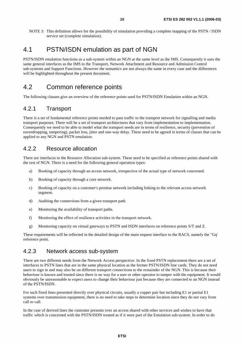
Figure 2 illustrates the legacy access types supported by the PSTN/ISDN Emulation Sub-system. The diagram is not intended to show all types of interface.
Z
S/T
Z
S/T
V5.2
AN AN
TISPANPSTN/ISDN Emulation
Subsystem
V5.2
PSTN/ISDN
Figure 2: Legacy access types
Figure 2 shows that the Legacy access types supported by the PSTN/ISDN Emulation Sub-system include:
• Analogue telephone via National Network Termination Point (NTP) (Reference Point Z).
• ISDN Basic Rate (S/T reference point) via an NTE provided on the customer premises.
• ISDN Primary Rate (T Reference Point).
• National Digital Primary rate variants as required.
• Access Networks using V5 signalling, (PSTN provided according to national mappings).

ETSI
ETSI ES 282 002 V1.1.1 (2006-03) 9
The list above is indicative only and not intended to be complete or exclusive. It is intended that inter-working between the PSTN and ISDN interface users be handled by the PSTN/ISDN Emulation Sub-system. The emulation sub-system also deals with the inter-working with Legacy PSTN and ISDN while they still serve customers.
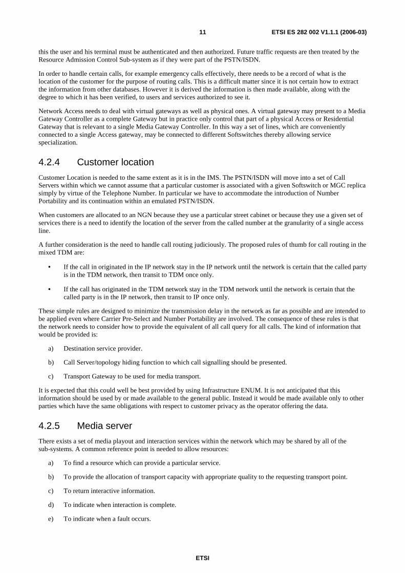
Figure 3 illustrates typical signalling configurations supported by the PSTN/ISDN Emulation Sub-system. For the sake of simplicity, only one type of access is represented on the left hand side. However, all combinations are to be supported by this sub-system. The diagram is intended to show how inter-working between instances of the PSTN/ISDN sub-system is done using ISUP messages and information elements when one of the inter-working parties is using ISDN signalling. This is meant to show the general case that SIP with encapsulated ISUP will be used to convey ISUP signalling within the NGN between ISDN legacy devices. Notwithstanding the use of SIP with encapsulated ISUP other SIP based signalling may be used to convey national signalling, as needed, within the general structure of an NGN.
In figure 3 there is reference to H.248 (ES 283 002 [5])but this is not to be taken as anything other than a reference to a specification that comprises information flows at a level commensurate with those expected within this architecture.
Z
H248
Z
H248
SIP-I
RGW or AGW
RGW or AGW
Z
H248 H248
SIP-I
RGW or AGW
H248
SIP-I
RGW or AGW
V5.2
V5.2/V5UA
ANZ
H248
S/T
DSS1/IUA
Z H248
H248
SIP-I
RGW or AGW
TGW
ISUP
PSTN/ISDN
Figure 3: PSTN/ISDN Emulation signalling configurations
An important principle of the emulation sub-system is that there is no intention to standardize the service set or signalling used in a national network or operator's network. The service set which is offered as part of emulation is expected to be a subset, which may range from only a small part of the feature set of the previous TDM network to a full implementation of the features of that network. The specification of the NGN emulation does not specify the extent or feature set within an NGN.
There are some features which an NGN emulation must be able to support if it is able to provide the functions of a Public Electronic Communications Network. These feature are specified in regulations in force in various states and the present document, and those to which it is related, assumes that these services are capable of being provided.
Emulation is defined within NGN as:
PSTN/ISDN Emulation: Provides PSTN/ISDN service capabilities and interfaces using adaptation to an IP infrastructure.
NOTE 1: Not all service capabilities and interfaces have to be present to provide an emulation.
NOTE 2: Those are definitions of the terms or concepts "simulation" and "emulation", not a definition of the architectural entities used to realize them. The architectural entity "emulation sub-system" is a consequence of the requirements posed on it, and it is called "emulation sub-system" because those requirements fit the above definition.
ETSI
ETSI ES 282 002 V1.1.1 (2006-03) 10
NOTE 3: This definition allows for the possibility of simulation providing a complete mapping of the PSTN / ISDN service set (complete simulation).
4.1 PSTN/ISDN emulation as part of NGN PSTN/ISDN emulation functions as a sub-system within an NGN at the same level as the IMS. Consequently it uses the same general interfaces as the IMS to the Transport, Network Attachment and Resource and Admission Control sub-systems and Support Functions. However the semantics are not always the same in every case and the differences will be highlighted throughout the present document.
4.2 Common reference points The following clauses give an overview of the reference points used for PSTN/ISDN Emulation within an NGN.
4.2.1 Transport
There is a set of fundamental reference points needed to pass traffic to the transport network for signalling and media transport purposes. There will be a set of transport architectures that vary from implementation to implementation. Consequently we need to be able to model what the transport needs are in terms of resilience, security (prevention of eavesdropping, tampering), packet loss, jitter and one-way delay. These need to be agreed in terms of classes that can be applied to any NGN and PSTN emulation.
4.2.2 Resource allocation
There are interfaces to the Resource Allocation sub-system. These need to be specified as reference points shared with the rest of NGN. There is a need for the following general operation types:
a) Booking of capacity through an access network, irrespective of the actual type of network concerned.
b) Booking of capacity through a core network.
c) Booking of capacity on a customer's premise network including linking to the relevant access network segment.
d) Auditing the connections from a given transport path.
e) Monitoring the availability of transport paths.
f) Monitoring the effect of resilience activities in the transport network.
g) Monitoring capacity on virtual gateways to PSTN and ISDN interfaces on reference points S/T and Z.
These requirements will be reflected in the detailed design of the main request interface to the RACS, namely the "Gq' reference point.
4.2.3 Network access sub-system
There are two different needs from the Network Access perspective. In the fixed PSTN replacement there are a set of interfaces to PSTN lines that are in the same physical location as the former PSTN/ISDN line cards. They do not need users to sign in and may also be on different transport connections to the remainder of the NGN. This is because their behaviour is known and trusted since there is no way for a user or other operator to tamper with the equipment. It would obviously be unreasonable to expect users to change their behaviour just because they are connected to an NGN instead of the PSTN/ISDN.
For such fixed lines presented directly over physical circuits, usually a copper pair but including E1 or partial E1 systems over transmission equipment, there is no need to take steps to determine location since they do not vary from call to call.
In the case of derived lines the customer presents over an access shared with other services and wishes to have that traffic which is concerned with the PSTN/ISDN treated as if it were part of the Emulation sub-system. In order to do
ETSI
ETSI ES 282 002 V1.1.1 (2006-03) 11
this the user and his terminal must be authenticated and then authorized. Future traffic requests are then treated by the Resource Admission Control Sub-system as if they were part of the PSTN/ISDN.
In order to handle certain calls, for example emergency calls effectively, there needs to be a record of what is the location of the customer for the purpose of routing calls. This is a difficult matter since it is not certain how to extract the information from other databases. However it is derived the information is then made available, along with the degree to which it has been verified, to users and services authorized to see it.
Network Access needs to deal with virtual gateways as well as physical ones. A virtual gateway may present to a Media Gateway Controller as a complete Gateway but in practice only control that part of a physical Access or Residential Gateway that is relevant to a single Media Gateway Controller. In this way a set of lines, which are conveniently connected to a single Access gateway, may be connected to different Softswitches thereby allowing service specialization.
4.2.4 Customer location
Customer Location is needed to the same extent as it is in the IMS. The PSTN/ISDN will move into a set of Call Servers within which we cannot assume that a particular customer is associated with a given Softswitch or MGC replica simply by virtue of the Telephone Number. In particular we have to accommodate the introduction of Number Portability and its continuation within an emulated PSTN/ISDN.
When customers are allocated to an NGN because they use a particular street cabinet or because they use a given set of services there is a need to identify the location of the server from the called number at the granularity of a single access line.
A further consideration is the need to handle call routing judiciously. The proposed rules of thumb for call routing in the mixed TDM are:
• If the call in originated in the IP network stay in the IP network until the network is certain that the called party is in the TDM network, then transit to TDM once only.
• If the call has originated in the TDM network stay in the TDM network until the network is certain that the called party is in the IP network, then transit to IP once only.
These simple rules are designed to minimize the transmission delay in the network as far as possible and are intended to be applied even where Carrier Pre-Select and Number Portability are involved. The consequence of these rules is that the network needs to consider how to provide the equivalent of all call query for all calls. The kind of information that would be provided is:
a) Destination service provider.
b) Call Server/topology hiding function to which call signalling should be presented.
c) Transport Gateway to be used for media transport.
It is expected that this could well be best provided by using Infrastructure ENUM. It is not anticipated that this information should be used by or made available to the general public. Instead it would be made available only to other parties which have the same obligations with respect to customer privacy as the operator offering the data.
4.2.5 Media server
There exists a set of media playout and interaction services within the network which may be shared by all of the sub-systems. A common reference point is needed to allow resources:
a) To find a resource which can provide a particular service.
b) To provide the allocation of transport capacity with appropriate quality to the requesting transport point.
c) To return interactive information.
d) To indicate when interaction is complete.
e) To indicate when a fault occurs.

ETSI
ETSI ES 282 002 V1.1.1 (2006-03) 12
f) To indicate when congestion or exhaustion of resources has occurred.
4.2.6 Presence
The PSTN/ISDN Emulation may act on behalf of customers to signal presence by direct invocation or as a result of activity monitoring. The PSTN may use the interfaces shared with IMS for this purpose to send messages on behalf of a presence. The presence information provided by the PSTN/ISDN Emulation sub-system includes user and call status resulting from a dialogue with the presence server. It can also act as a watcher offering call completion services linked to presence.
4.2.7 Messaging
The PSTN/ISDN emulation is related to the Messaging system in that it is a delivery mechanism for the Fixed SMS and MMS services.
4.2.8 Application servers
The PSTN/ISDN Emulation shall also have the ability to use services mounted on the same style of application servers as those in the IMS. This will allow new services to be provided in common with the IMS and offer new services to PSTN/ISDN customers. In order to use these services it is likely that there will need to be a co-ordination function and access to user data relating to the services in the PSTN/ISDN Emulation domain.
4.2.9 Customer data
Customer Data needs to be made accessible by Application servers and also by management systems. These interfaces are best co-ordinated with IMS and for that purpose are likely to share a common reference point or points with the IMS.
5 Overall architecture
5.1 Functional entities In specifying the Functional Entities in the NGN we bear in mind that there are many existing implementation which are either complete or in development. It is therefore inappropriate to attempt to standardize in an over prescriptive manner. The intention is only to standardize the information flows in and out of the PSTN/ISDN Emulation Sub-system and not to prescribe a particular implementation.
The following functional entities appear to be necessary from the perspective of specifying information flows and ensuring the interoperability of services:
• Access Gateway Analogue line function.
• Access Gateway BRI function.
• Access Gateway PRI function.
• Residential Gateway Analogue line function.
• Residential Gateway BRI function.
• Trunk Gateway function.
• Access Call Server function.
• Transit Call Server function.
• Packet Handler Gateway function.

ETSI
ETSI ES 282 002 V1.1.1 (2006-03) 13
• Media Gateway Controller function.
• Media Server Control Function.
• Customer Location function.
• IN Access Sub-system.
• SIP Server Access Function.
• Trunk Signalling Gateway.
Not all of these functions are shown in the following diagram in figure 4.
DistributorS
ervice A
Service B
Service C
MasterCustomer
Data
CustomerLocation
TrunkRouting
Service 1
Service 2
Service 3
PSTN/ISDNServices
AGCF TGCF
SGCF
AGF
AGF
S/T
Z
AS
MGF
e
A-BGF I-BGF
RACS
IN
PSTN/
ISDN
RG
Gq’
TopologyHiding
Gateway
OtherNGN’s
OtherNGN’s
PSTN/ISDNEmulationSubsystem
Transport
b
a
c
f
g
h
j
i
AGCF
NOTE:Lines inside the grey area are purely illustrative. Information flows mayBe though the DistributorOr direct as an implementation option
LocalData Distributor
Service A
Service B
Service C
MasterCustomer
Data
CustomerLocation
TrunkRouting
Service 1
Service 2
Service 3
PSTN/ISDNServices
AGCF TGCF
SGCF
AGF
AGF
S/T
Z
AS
MGF
e
A-BGF I-BGF
RACS
IN
PSTN/
ISDN
RG
Gq’
TopologyHiding
Function
OtherNGN’s
OtherNGN’s
PSTN/ISDNEmulationSubsystem
Transport
b
a
c
f
g
h
j
i
AGCF
NOTE:Lines inside the grey area are purely illustrative. Information flows mayBe though the DistributorOr direct as an implementation option
LocalData
Presence
Server
ki i
DistributorS
ervice A
Service B
Service C
MasterCustomer
Data
CustomerLocation
TrunkRouting
Service 1
Service 2
Service 3
PSTN/ISDNServices
AGCF TGCF
SGCF
AGF
AGF
S/T
Z
AS
MGF
e
A-BGF I-BGF
RACS
IN
PSTN/
ISDN
RG
Gq’
TopologyHiding
Function
OtherNGN’s
OtherNGN’s
PSTN/ISDNEmulationSubsystem
Transport
b
a
c
f
g
h
j
i
AGCF
NOTE:Lines inside the grey area are purely illustrative. Information flows mayBe though the DistributorOr direct as an implementation option
LocalData
Presence
Server
ki i
f
m
d
NOTE: Lines inside the grey are purely illustrative. Information flow may be though the Distributor or direct as an implementation option.
Figure 4: Overview of Functional Entities
It is rather easy to assume that diagrams such as figure 4 convey more information that than was intended when assumptions are made by the reader. To avoid this the following description is included.
The Functional Architecture is shown in figure 4 in such a way that it can be seen that multiple implementation architectures are possible. There are some fundamental points that should not be missed however. The first of these is that we have gateways that convert legacy interfaces such as national analogue PSTN Z reference points and ISDN S or T reference points into NGN interfaces. These are usually thought of as being H.248 interfaces but that is not the only interface that can be used. Depending on the service set MGCP or interfaces carrying suitable information in SIP can be used. The key point is that the information flow can carry the stimulus information traditionally needed in national PSTNs to carry both line and register signalling from customers as well as specialized service signalling.
Trunk Gateways may also be H.248 but once again MGCP and SIP could be used. Again the key point is that the information flow can carry the line and register signalling needed to interface to physical TDM trunks in the PSTN/ISDN.
ETSI
ETSI ES 282 002 V1.1.1 (2006-03) 14
The shaded area is to be taken as that set of functions which, taken together, provide the Emulation of a PSTN or ISDN. The use of a message distributor between the various parts of the Sub-system is optional and may be replaced by direct links if preferred. Note also that the PSTN/ISDN service is shown as the aggregate of Services 1 to 3. This is because existing implementations are sometimes spread amongst different servers where a consideration of service interactions permits this.
The AGCF is concerned with the control of Access lines and the TGCF is concerned with Trunk circuits are shown as separate from the PSTN/ISDN services there is no reason to force them to be separate. An implementation is free to combine any of these functions in the shaded area in any way.
There will only be a limitation where the interfaces may be opened up to the rest of NGS. For example when IMS application servers are added for new services, as in Services A, B and C, the interface will be SIP so as to align with IMS. Also in this case the instance of the Distributor will be a CSCF.
Trunk Routing represents a policy function that determines the routing for a given call. It may also need to consult Customer Location which determines the server or network that signalling is sent to for a given PSTN customer. This function will work whether the customer concerned is on the Emulation/NGN or Simulation of a PSTN or the traditional PSTN.
The functions shown as Services 1, 2 and 3 are just examples. They represent the basic call service and that set of supplementary services that are embedded in the Call Server. They are shown as Services 1, 2, etc. in order to highlight the possibility that the embedded services including basic call are distributed.
Calls are offered into the PSTN/ISDN via Signalling and Media Gateways or into other Emulations, or IMS based NGN Sub-systems, direct from Call Servers or via Topology Hiding Functions. The Topology Hiding Function may be co-located with a Call Server. It is these latter two entities that are identified by the Customer Location function. The Topology Hiding Function (THF) performs similar functions to the IBCF function used in the IMS sub-system. The IBCF function is not used in PSTN/ISDN Emulation sub-system. Instead the Topology Hiding Function operates on the signalling as encapsulated NNI signalling, e.g. SIP with encapsulated ISUP, and controls the BGF accordingly via the SPDF in the Resource and Admission Control Sub-system.
Customer services data is often only kept near the service instances in PSTNs. In order to interwork with IMS AS replicas there is a need to offer customer data as if the PSTN forms part of the UPSF. The AS is then able to request data about customers. This will be common to the IMS part of NGN.
Only an interface from the PSTN/ISDN services is shown here because if an independent request is needed from an AS it will be acting as an AS in the IMS, the architecture of which is shown elsewhere. The AS replicas and the services in the PSTN/ISDN Emulation act as Application Functions from the perspective of the RACS.
Media Servers are omitted from figure 4 the protocol choice for them is outside the scope of the present document but they are not regarded as Application Servers for the purpose of figure 4. Messaging servers may also be addressed by the Call Servers or by Application Servers, the architecture does not treat Messaging Servers as Application Servers.
5.2 Reference points The specification of reference points is strictly limited to those places where interworking is desirable either between networks or between manufacturers.
At present it is expected that these reference points will be:
• Between AGF (analogue) and AGCF.
• Between AGF (BRI) and AGCF.
• Between AGF (PRI) and AGCF.
• Between MGF (Trunk) and TGCF.
• Between SGCF and PSTN (STP).
• Between Call Server/Topology Hiding Function and other NGNs.
• Between PSTN/ISDN services and RACS (Gq').
ETSI
ETSI ES 282 002 V1.1.1 (2006-03) 15
• Between Customer data and NASS for physical Location information.
• Between Services and Customer Location Function.
• Between Customer Data and Application Servers.
• Between Call servers and Presence Server.
The following clauses go into a little more detail on the expectation for information flows across the above reference points.
5.2.1 Between AGF (analogue) and AGCF (a)
This reference point is used to specify the information flows between Analogue line interface devices, expected to be Access Gateways, and the PSTN/ISDN Service components. The information flows are expected to be at the level of messages associated with sending and receiving Line and Register signalling from Customer lines connected to the gateway. The Analogue Gateway may send information flows either direct to the PSTN/ISDN Services entity/entities or via a distributor function.
5.2.2 Between AGF (BRI) and AGCF (b)
This reference point is used to specify the information flows between ISDN Basic Rate line interface devices, expected to be Access Gateways, and the PSTN/ISDN Service components. The information flows are expected to be at the level of messages associated with sending and receiving DSS1 and in-band Register signalling from Customer lines connected to the gateway. The Access Gateways may send information flows either direct to the PSTN/ISDN Services entity/entities or via a distributor function.
5.2.3 Between AGF (PRI) and AGCF (c)
This reference point is used to specify the information flows between ISDN Primary Rate line interface devices, expected to be Access Gateways, and the PSTN/ISDN Service components. The information flows are expected to be at the level of messages associated with sending and receiving DSS1 and in-band Register signalling from Customer lines connected to the gateway. The Access Gateways may send information flows either direct to the PSTN/ISDN Services entity/entities or via a distributor function.
5.2.4 Between MGF (Trunk) and TGCF (d)
This reference point is used to specify the information flows between TDM Trunk interface devices, expected to be Trunk Gateways, and the PSTN/ISDN Service components. The information flows are expected to be at the level of messages associated with sending Line and Register signalling from Trunk circuits connected to the gateway. The Trunk Gateways may send information flows either direct to the Trunk Gateway Control Function or via a distributor function.
5.2.5 Between SGCF and PSTN (STP) (e)
This reference point appears between the Signalling Gateway and PSTN/ISDN Signalling Devices. The information flows across this interface are expected to relate to signalling used for Call Control and Supplementary Services as well as IN signalling.
5.2.6 Between Call Server/Topology Hiding Function and other NGNs (f)
This reference point appears between NGNs when a Topology Hiding Function is used by one both of the networks concerned. The information flows across this reference point are those associated with an NNI for PSTN/ISDN services including IN services where the Interconnect is based on IP.
ETSI
ETSI ES 282 002 V1.1.1 (2006-03) 16
5.2.7 Between PSTN/ISDN services and RACS (g) (Gq')
This reference point is shared with other sub-systems and is a general one for requesting facilities of the RACS. The information flow is used to request the capacity to create resources for the conveyance of media flows and to request that the capacity is withdrawn when no longer used. It is expected that it will also carry information about the loss of capacity, such events may result from infrastructure rearrangements or faults.
5.2.8 Between Customer data and NASS for physical Location information (h)
This reference point is a re-use of the NASS reference point and may only be useful where derived voice services are offered. The information flow is related to customer location and is sent in the event of terminal registration and de-registration.
5.2.9 Between PSTN/ISDN Emulation Sub-system and IMS application servers (i)
This reference point enables the PSTN/ISDN Emulation sub-system to invoke value-added services as defined by a particular user's profile. For maximum commonality and re-use across sub-systems in the TISPAN NGN architecture, value-added services (labelled Services A, B and C in figure 4) are assumed to be deployed in IMS Application Servers and therefore, the choice of protocol and information flows across the i reference point are equivalent to those of the ISC reference point in the IMS sub-system. For more information, please refer to clause 9.2. IMS application Servers.
In addition this reference point shall be able to carry IMS SIP signalling in TS 124 229 [1] to other IMS components and may be used to interconnect to an IMS using SIP. This reference point shall also enable presence-related subscriptions, notifications and publications between IMS Application Servers and the PSTN/ISDN Emulation Sub-system.
5.2.10 Between Customer Data and Application Servers (j)
The reference point is used to carry information flows to populate Application Servers with customer data. This is a reference point shared with the IMS and so will probably use the protocols as are defined for that reference point.
5.2.11 Between call servers and presence servers (k)
This reference point is used to carry presence information and is equivalent to the pen reference point described in TS 123 141 [2]. The Call Server decides on what presence information to send based on:
• explicit signals from the user; or
• as a result of interpreting the state, and/or changes in state, of a PSTN/ISDN user.
Additionally, in response to a request from a Presence Server, made to the call server monitoring the user's state,: the Call Server activates or deactivates monitoring and supplies, or updates, a specified subset of presence information about the user.
5.2.12 Between services and customer location function (m)
The services referred to in this clause may be those associated with the servers providing PSTN/ISDN emulation services (e.g. those numbered 1 to 3 in figure 4) and by different servers offering other, perhaps more advanced, services (e.g. those lettered A to C in figure 4). The information flows across this reference point are to allow servers to find where signalling is to be sent to reach the destination user or his signalling agent. An example implementation may include the use of ENUM or other DNS servers.
ETSI
ETSI ES 282 002 V1.1.1 (2006-03) 17
5.3 Guidance on protocol issues It is the clear intention of this architecture that there be a range of implementation architectures that can equally well implement the functionally architecture.
There is no intention within this architecture that protocols should be specified within the shaded area of figure 4. For the reference points outside the shaded area there are some standard protocols that appear to fit the needs of information flows. It is not intended that any limit be placed on protocol choices for each information flow. As an example the Line and Register signalling from the Analogue Gateway could be carried in more than one protocol - the obvious one being H.248.
5.3.1 Guidance for Internal protocols
It is not the intention that protocol choices should be made in standards for the functions shown within the shaded area of figure 4. However the following guidance is offered to implementers:
In order to allow simple adding of functional replicates it is recommended that the shaded area in figure 4 be treated as a secure zone. This means that steps should be taken to ensure that communications from outside the zone are controlled. Devices within the zone should communicate with each other in a manner that can be differentiated from communications from outside the zone.
Within the zone the reliability needed for transport may only be determined by reference to the application protocols concerned and that is a matter for implementers.
Implementers should recognize that the network inside the zone is not the Internet. Implementers should determine appropriate security measures commensurate with the risks encountered in the zone. Full consideration should be given to the effects of security measures on performance as part of the risk assessment [2].
5.4 PSTN/ISDN emulation using IMS Readers should note that TISPAN is also producing a further document that will describe the use of IMS components to provide the PSTN/ISDN Emulation Sub-system in a different way to that envisaged in the present document. For that reason the present document will not discuss the use of IMS servers for core services but will discuss their common use as feature additions to the PSTN.
6 Resource allocation Within a PSTN/ISDN emulation the range of requests that may be sent to the Resource an Admission Control Sub-system is significantly less flexible that for the IMS and other sub-systems. This is because the PSTN/ISDN Emulation Sub-system only has to request resources that match the existing PSTN and ISDN bearer capabilities.
There is a need to request a connection-oriented media flow that allows unidirectional or bidirectional media flows. Optionally the request may contain provision for RTCP in the same directions of flow as for the media. Again optionally the RTCP may be requested on specified ports rather than on adjacent ports to the media as would happen by convention.
Within the present document an analysis of the architecture is performed. It should be noted that this is not the same as the requirements actually placed on the RACS sub-system. The model here is used only to generate information flow requirements. In all cases the actual information flows and requirements for RACS shall take precedence in implementation. The present document is only an input document to the RACS.
The behaviour for PSTN/ISDN emulation requests should be that resources are reserved for both directions of transmission in order to ensure that the resources are available when needed. This is because it is normal to change flows from one way to two way, and back, with normal call flows as media "path split" is applied and removed.
Whilst the normal use of the PSTN/ISDN network is to make telephone or data calls there are also some uses of it for Private Circuits between PSTN/ISDN endpoints. In some networks these are controlled by the PSTN/ISDN service controllers and account is taken of this in the architecture that follows.
ETSI
ETSI ES 282 002 V1.1.1 (2006-03) 18
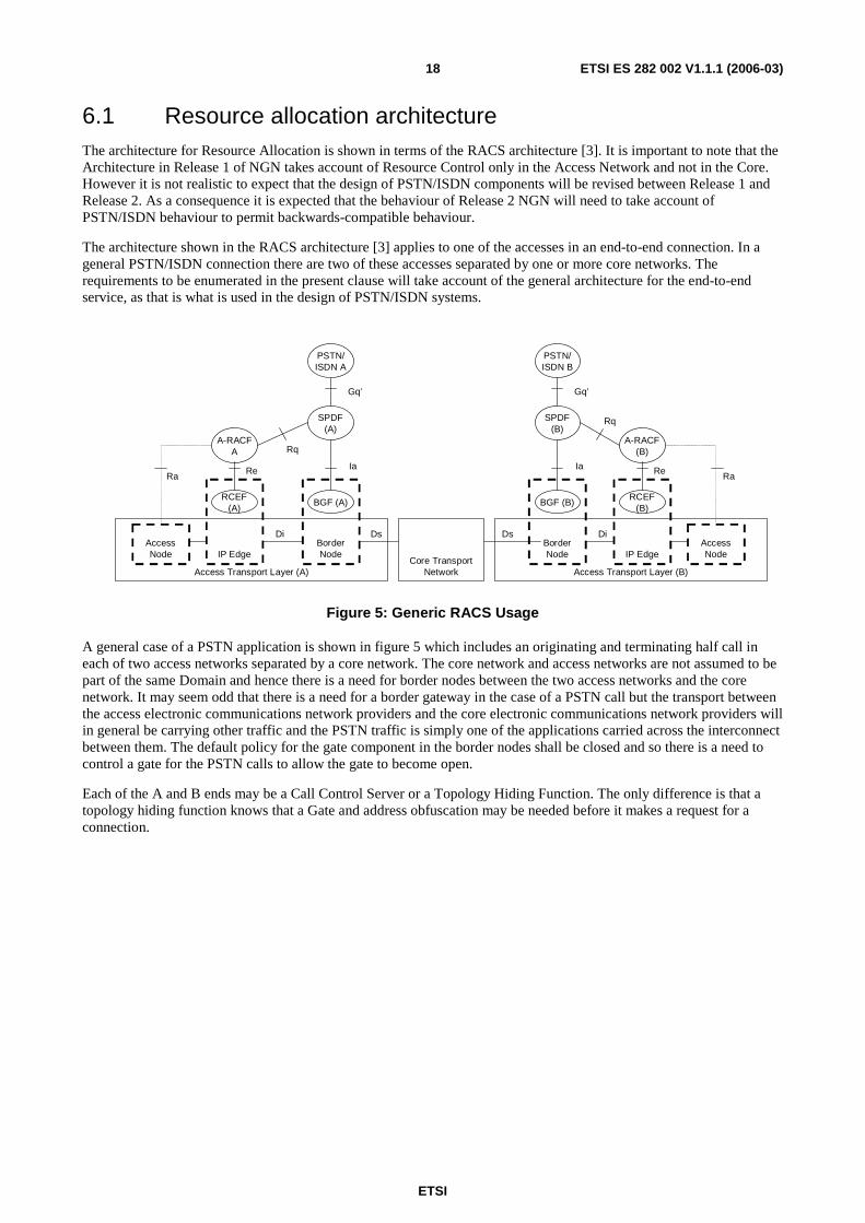
6.1 Resource allocation architecture The architecture for Resource Allocation is shown in terms of the RACS architecture [3]. It is important to note that the Architecture in Release 1 of NGN takes account of Resource Control only in the Access Network and not in the Core. However it is not realistic to expect that the design of PSTN/ISDN components will be revised between Release 1 and Release 2. As a consequence it is expected that the behaviour of Release 2 NGN will need to take account of PSTN/ISDN behaviour to permit backwards-compatible behaviour.
The architecture shown in the RACS architecture [3] applies to one of the accesses in an end-to-end connection. In a general PSTN/ISDN connection there are two of these accesses separated by one or more core networks. The requirements to be enumerated in the present clause will take account of the general architecture for the end-to-end service, as that is what is used in the design of PSTN/ISDN systems.
BorderNodeIP Edge
PSTN/ISDN A
A-RACFA
SPDF(A)
RCEF(A)
BGF (A)
AccessNode
Access Transport Layer (A)
RaRe Ia
Gq’
DsDiBorderNode
PSTN/ISDN B
SPDF(B)
BGF (B)
Ia
Gq’
Ds
IP Edge
A-RACF(B)
RCEF(B)
Re
AccessNode
Ra
Access Transport Layer (B)Core Transport
Network
Rq
Rq
Di
Figure 5: Generic RACS Usage
A general case of a PSTN application is shown in figure 5 which includes an originating and terminating half call in each of two access networks separated by a core network. The core network and access networks are not assumed to be part of the same Domain and hence there is a need for border nodes between the two access networks and the core network. It may seem odd that there is a need for a border gateway in the case of a PSTN call but the transport between the access electronic communications network providers and the core electronic communications network providers will in general be carrying other traffic and the PSTN traffic is simply one of the applications carried across the interconnect between them. The default policy for the gate component in the border nodes shall be closed and so there is a need to control a gate for the PSTN calls to allow the gate to become open.
Each of the A and B ends may be a Call Control Server or a Topology Hiding Function. The only difference is that a topology hiding function knows that a Gate and address obfuscation may be needed before it makes a request for a connection.

ETSI
ETSI ES 282 002 V1.1.1 (2006-03) 19
A simplification of this architecture can be derived in the case of a call where the networks involved are in the control of a single network provider and is shown in figure 6.
IP Edge
PSTN/ISDN A
A-RACFA
SPDF(A)
RCEF(A)
AccessNode
Access Transport Layer (A)
RaRe
Gq’
DsDi
PSTN/ISDN B
SPDF(B)
Gq’
Ds
IP Edge
A-RACF(B)
RCEF(B)
Re
AccessNode
Ra
Access Transport Layer (B)Core Transport
Network
Rq
Rq
Di
Figure 6: RACS Usage for Single Provider case
There is a further case of note which is generally related to private circuit use but may also be chosen when operation is intended to be exclusively restricted to a single network provider domain in which there is a single requesting PSTN/ISDN call control instance. This case is outside the scope of control by RACS. It will be necessary to provide such circuits by using the network management system rather than any per call scheme. Whist RACS will not have to co-ordinate the two ends the other considerations described later will still apply using the two end requestor model. Permanent pinholes for signalling etc. will also be handled by the management system.
Note that the role of Application Function (AF) can be performed by call servers, Application Servers or any other appropriate function that uses the Gq' reference point.
6.2 Modes of operation
6.2.1 One and two phase commit
In PSTN and ISDN emulation there are two different modes of transport operation which correspond to One and Two-phase commit. In the first case the call is established wholly between access gateways or residential gateways that are wholly under the control of the network provider(s). Because the equipment is known to work correctly and to interoperate there is an assumption that the call control operations on the media gateways will be co-ordinated such that two-way speech is not possible without payment for the call. Because the design can offer speech path policing without direct action by the transport network it is possible to have a single operation that requests a symmetrical media flow.
On the other hand persons who are not trusted by the network provider (s) could operate some access gateways or residential gateways and the means of fraud prevention may be to provide only a one-way path for the conveyance of call progress tones and permit two-way transmission only after payment is assured. It is essential that if payment is to be taken the resources needed for the second direction of transmission be assured at the same time as the first direction. There is therefore a need for a two-stage commit mechanism.
Having shown a need for both single and two stage mechanisms we have also to be aware that only the PSTN/ISDN emulation service, or Application Function, can tell which mechanism is appropriate for a given transport path and systems must allow for both.
6.2.2 Single and double requesters
In the previous clause it was identified that there is a need for double request operation where separate requests are made for each access network. Where the two ends of the call are associated with different access networks each of the relevant call control objects, media gateway controllers or call servers, make a request of their own access RACS. For the network they control it is essential that they request transmission capacity in both directions.
ETSI
ETSI ES 282 002 V1.1.1 (2006-03) 20
In Release 1 we assume that the core is not controlled by RACS however the information flow must be compatible between Release 1 and Release 2. In order to make this possible the two end must both control the core to the same degree and an appropriate mechanism is to have the core admission control effected by each requesting A-RACS forwards to the edge of the other A-RACF's domain through the core. The means of sending requests between A-RACF and C-RACF is not within the scope of the present document. However, when the core network or networks are access controlled there shall be no additional information flow from the PSTN/ISDN Emulation Sub-system. This is a requirement for backwards compatibility of Release 2 with Release 1 information flows.
It was also shown that in one mode of operation the PSTN/ISDN Emulation expects that one request will cover the operation of a Border Gate as well as allocating resources in the RACF, and potentially with the Access Node. In the other mode the Border Gate and RACF are controlled by different operations co-ordinated by the Call Server.
6.2.3 Hard and soft State for Recovery
It must be anticipated that at some point the A-RACF may fail due to equipment malfunction. There are two principal strategies that may be adopted to allow recovery from such events. In the first the state of a committed transport flow can be backed up as an atomic transaction and the call control, MGC or call server, can assume perfect recovery of state. This mode requires audit schemes to ensure that state is synchronized with the controlling Application Function in the PSTN/ISDN Emulation Sub-system.
A second mode of operation is that state about flows is allowed to time out and if flows persist for a long time there is a need to refresh the knowledge in the A-RACF. In this case the transactions do not need to secured at the same rate. The characteristics on failure are different and loss of state information results in a period where state information is rebuilt from the last secured position and after the timeout period the state is fully recovered. The timeout mechanism also removes the need for audit to track down reservations that have become orphaned from Call server state.
Both mechanisms have their place and both hard and soft state shall be supported by the architecture and information flows. It should be noted that this will result in a refresh primitive in the information flow but a separate refresh message is not mandated at the protocol level.
6.2.4 Transmission faults
Faults in the transport network will occult and the A-RACF may become aware of them by appropriate means. It is a requirement that the A-RACF is able to notify the PSTN/ISDN Emulation Sub-system of media paths that have failed. The strategy for how to do this is implementation dependent.
Implementers may choose to rely on detection mechanisms such as user cleardown, loss of RTP/RTCP etc to allow the faulty calls to clear down as a consequence of the transmission loss. The capacity lost as a consequence of the fault is not available in the A-RACF after the fault has been detected. The failed capacity is therefore not allocated for new flow requests. Some period after the flow has ceased as a result of the fault the A-RACF will report the loss of transport to the PSTN/ISDN Emulation Subsytem as a path loss. In turn the PSTN/ISDN Emulation Sub-system will cleardown the associated Call Control State.
For some kinds of path, notably special purpose pinholes and Private Circuits, there will be nothing to detect the fault. It is possible that for some kinds of connection implemented as an IP media flow there will be a need to terminate the PSTN/ISDN Emulation Call state faster than for other flows. An example is a Private Circuit with no human user, on fault notification the emulation sub-system may re-establish the path as a matter of urgency. It is common to set up Private Circuits with priority when switch faults have occurred.
There is therefore a requirement to report the loss of a flow state due to a fault after a time determined by the PSTN/ISDN Emulation Sub-system. The time to elapse before reporting a fault shall be variable on a per call basis but need not be a continuous variable. Two or three values may suffice such a long medium and short. The actual values will be set based on commercial grounds and with due regard to the self-healing properties of the transport network involved.
6.2.5 Overload
There is a requirement that overload on the PSTN/ISDN Emulation Sub-system to RACS interface be handled. When the RACS is overloaded the resulting loss of capacity should be reported to the PSTN/ISDN Emulation Sub-system. When faults occur it is possible that when timers expire a large number of failed flows need to be notified to the PSTN/ISDN Emulation Sub-system. These requests may overload the Call Server or MGC.

ETSI
ETSI ES 282 002 V1.1.1 (2006-03) 21
There is a requirement that overload control is available between PSTN/ISDN Emulation Sub-system and RACS in both directions. The efficiency of the control is most important in the case of potential overloads on RACS since that does not represent a fault case.
6.2.6 Gate control
The control of gates in Border Gateways is closely associated with the admission control function in RACF. So much so that both operations are shown as being accessible through the same reference point Gq'. However whilst RACF is allocating capacity on the basis of a perfect flow and can cope with a limited description of the flow requirements a Gate requires rather more rigorous specification of the flow. This is because a Gate will need to have the flow specification in terms of average and peak bit rates and details of the leaky bucket algorithm to be used. This information is usually referred to as a flow specification.
If a Gate applied header translation it will be necessary to either supply the binding to the gate or receive the binding back from the Gate. Such binding may involve translations of IP Address and/or Port numbers. In addition the opening of RTCP as well as RTP may be required either on standard or non standard ports. In the cause of efficiency these variations should all be handled without extra information exchange.
The information for Gate control shares some information with the Admission control flow but other information is specific to Gate control. It is required that either or both operations may be controlled with the same information flow in the cause of efficiency. Equally, if desired by the PSTN/ISDN Emulation the Gate control and admission operations may be performed separately. When performed separately the operations shall have different identifiers for response and notification correlation.
6.2.7 Bearer capabilities
Within the PSTN/ISDN there are a number of bearer capabilities. In practice these are usually implemented inside the PSTN/ISDN as 64 kbit unrestricted bearers. There are exceptions where calls traverse non-transparent transmission facilities such 56 kbit mu law systems, TASI systems, fax relay and analogue transmission systems. In PSTN/ISDN emulations using Access Gateways these transmission systems are connected to specialist gateways and the emulation sub-system only needs to provide 64 kbit/s clear channel connections in a symmetrical way.
For ISDN the vast majority of calls use forms of channel bonding which means that only 4 kbit clear channel is required for that service. However there remains a residual amount of N × 64 kbit/s ISDN equipment. The expectation of terminals for such services is that the channels are subject to the same transmission conditions as each other. Therefore when conveying N × 64 kbit/s services the PSTN/ISDN Emulation Sub-system shall request the RACS to provide a single flow sufficient to convey all n channels. The packetization details needed to use the flow are not in the scope of the present document. The requirement on the RACS is to allow bidirectional flows for 64 kbit/s clear channel calls and for N × 64 calls for users on Access Gateways connected to a PSTN/ISDN Emulation.
The Interfaces shall be capable of conveying flow specifications that correspond to 64 bit clear channel calls using at least 10 ms and 20 ms packetization period. It is desirable that lower packetization periods may also be indicated in the flow descriptor.
6.2.8 Priority
The information flows shall provide for a number of priority types. A particular request may ask for one or more priority types simultaneously. This is because we have multiple reasons for applying priority but standards do not indicate how they interact one with another. For example, the priority associated with a line used for Authority to Authority calls and it being used to dial the emergency code for Citizen to Authority (112, 999, 911) are completely separate. Whilst the former gives priority resource allocation the latter may include multiple retries until the call is connected. The actual behaviour for combinations is a national matter and the actual behaviour will be implementation dependent.

ETSI
ETSI ES 282 002 V1.1.1 (2006-03) 22
It is a requirement that at least eight different priority types be defined such that any number of them may be simultaneously active. The design of the information flow and subsequent protocol shall be such that any one priority may cause at least the following possible behaviours:
a) Use of a separate resource pool for fulfilling the request.
b) Providing priority when contending for resources such as by-passing queues for resources allocated on a delay basis.
c) Providing continuous retries for resources allocated on a demand basis.
And as a national option:
d) Providing facilities for pre-emption of flows.
6.2.9 Derived PSTN/ISDN calls
When the PSTN/ISDN user has a residential gateway it may be managed as part of the public electronic communications network. It may be at the end of aDSL, or some other kind of, limited capacity transmission system. It is a function of the A-RACF to ensure that sufficient priority and capacity is provided for the call on the Access System. In order to maximize the number of calls on such links the codec used may be one with a lower bit rate that A/mu law clear channel. The protocol used to convey information across the Gq' reference point shall be able to convey a range of codec bit rates such as not to limit the choice of low rate codecs for derived voice services. ISDN residential gateways will use the same packetization schemes and have the same protocol requirements as for Access Gateways.
When a codec other than A/mu law is used there is a need to perform transcoding. The Gq' reference point shall be capable of conveying the information needed to control a transcoder wherever it may be in the access network. This requirement extends to controlling the transcoder via the Rq reference point and any one of the Ia, Re and Ra reference points and their associated protocols.
The residential gateway may be situated inside a customer premises network in which case address and port translation binding may be required at the edge of the customer premise in his gateway router. Where this is so the control is as for a gate and gate control with bindings allocated by the network or the customer gate in his gateway may be required. The control of a gate at the customer side shall use the same information flows and preferably the same protocol as the border node gate. As for the border node gate it shall be possible to combine operations across Gq' on the same operation reference or to use multiple operations each with a unique reference.
The requirement identified so far show that operations of Border Node Gate (Ia), IP edge (via Re), within the Access System (via Ra), transcoder and if available in a customer gateway gate (via a second instance of Ia) may all be combined in a single operation or provided as separate operations. The more general requirement is that any or all of these actions should be conveyed in a given information flow and the protocol shall be capable of conveying which actions are required. In release 2 it is clear that further options relating to actions in the core will be needed. Therefore the information flow must be capable of indicating which parts of the network require to be bound to the operation identified by the particular reference in the current request. The network segments identified earlier need to be covered as well as an extensible set of core and customer network segments. The protocol shall be capable of identifying which information elements are relevant to each network segment.
6.2.10 Three and more party calls
Unlike SIP conferencing which occurs at the terminal the PSTN model uses conference bridges that are introduced in to the media flow. In order to efficiently insert a bridge and to re-arrange the media flow the call control needs to see the actual topology used so that it can choose where to place a bridge and what changes in the media flow address and ports are required. In architectures such as TIPHON the media layer abstracts this detail away from the call control layer but in TISPAN there is no Media Layer and the details of the transport arrangements must be disclosed to the call control entities.
There is a possibility that header translation devices exist in the path and the call control was unaware of them when it requested the initial connection. In order to make the call control aware of the devices and inform it of the issues for re-arrangement on insertion of a bridge the RACS shall include details of all gateway devices and their settings in the responses of information flows that establish media connections.
ETSI
ETSI ES 282 002 V1.1.1 (2006-03) 23
6.3 Functional entity model There has been considerable work done elsewhere on this subject in the MSF and in ETSI TIPHON. Many of the appropriate Information elements and primitives are described in [4].
6.3.1 Description of Model
AF
SPDF
RACF
ra(Gq’)
rb
1..2
Figure 7: Functional Entity relationship diagram
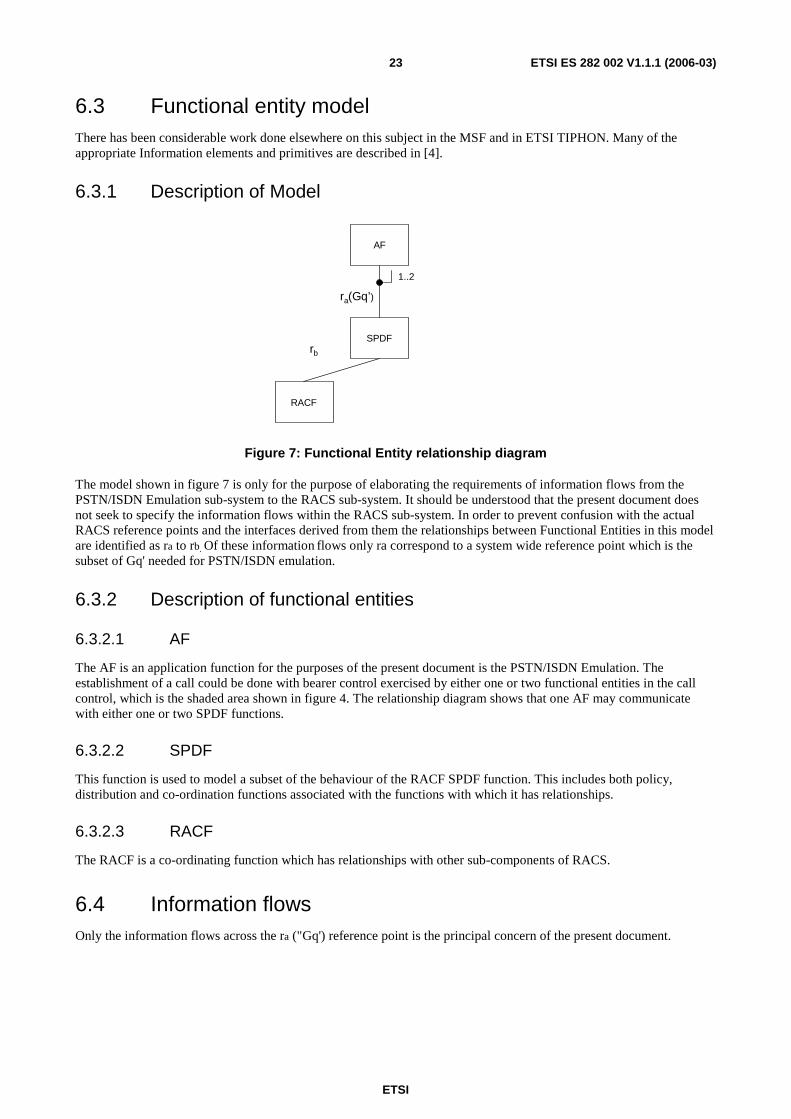
The model shown in figure 7 is only for the purpose of elaborating the requirements of information flows from the PSTN/ISDN Emulation sub-system to the RACS sub-system. It should be understood that the present document does not seek to specify the information flows within the RACS sub-system. In order to prevent confusion with the actual RACS reference points and the interfaces derived from them the relationships between Functional Entities in this model are identified as ra to rb. Of these information flows only ra correspond to a system wide reference point which is the subset of Gq' needed for PSTN/ISDN emulation.
6.3.2 Description of functional entities
6.3.2.1 AF
The AF is an application function for the purposes of the present document is the PSTN/ISDN Emulation. The establishment of a call could be done with bearer control exercised by either one or two functional entities in the call control, which is the shaded area shown in figure 4. The relationship diagram shows that one AF may communicate with either one or two SPDF functions.
6.3.2.2 SPDF
This function is used to model a subset of the behaviour of the RACF SPDF function. This includes both policy, distribution and co-ordination functions associated with the functions with which it has relationships.
6.3.2.3 RACF
The RACF is a co-ordinating function which has relationships with other sub-components of RACS.
6.4 Information flows Only the information flows across the ra ("Gq') reference point is the principal concern of the present document.
ETSI
ETSI ES 282 002 V1.1.1 (2006-03) 24
6.4.1 Definition of information flows across ra
Based on the requirements stated in clause 6.2 Modes of operation, the necessary information flows are derived with the context of the model shown in figure 7. The following is a list of operations needed with a brief description:
1) ReservationRequest The first stage of a two stage commit process where the transport facilities are requested and reserved if available. In the case of a derived call one direction of transport may also be committed using this action.
2) ReservationCommit The second stage of a two stage commit process where the transport facilities are put into use. For derived voice this would enable a path split to be removed within the network without trusting a residential gateway. note that the residential gateway can be beyond a trusted customer gateway device.
3) ReservationRequestAndCommit Used for reservation and commit function, used for single stage commit such as when access gateways and/or trunk gateways only are present in a call.
4) ReservationModify Used for derived voice to change codecs based on capacity available on access line.
5) ReservationRelease Releases all transport functions in use and removes reservations.
6) ReservationLost A fault indication from the transport layer that a reservation has become ineffective and call control may, at its discretion, clear down the call and optionally re-establish transport via different routes if that is possible or appropriate.
7) ReservationNotify Used to notify the call control of any event which may be detected in the transport. Examples of such events could be the access system requesting that a lower rate codec be used because of other subscription requests, an attempt to over-subscribe the policing function or excessive error rates or just lost of transmission of RTP. The latter event should be used sparingly to prevent overload conditions under faults.
8) ReservationRefresh Used by call control to notify the transport resources that the call is a long lasting one and that the existing resources are still in use. Failure to refresh would cause the transport to clear down the connection and report that fact using a ReservationLost operation. The use of this method prevents the creation of orphaned transport facilities.
9) OverloadState A request to limit the number of requests to a percentage of normal load in the direction PSTN/ISDN Emulation to RACS. Additionally it may be the number of ReservationNotifys or ReservationLosts to be sent per unit time in the direction RACS to PSTN/ISDN emulation.
The details of Information Elements to be sent on each request and the information on responses is included within the TISPAN RACS requirements [3].
6.5 Timers This clause provides details of the timers identified in the information flow sequences.

ETSI
ETSI ES 282 002 V1.1.1 (2006-03) 25
6.5.1 SPDFRespTimer
This timer covers the delegation of tasks to the RACF and other sub-functions of RACS. In Release 1 this timer does not need to cover communication with the core network. Given that the RACF also communicates with other devices it would be unreasonable to expect that the average delay is less than 10 ms to 20 ms before the final response is likely to arrive. Given the need to allow for load variation a timeout figure of around 50 ms to 100 ms is needed. It is recommended that 50 ms is used unless the load of the SPDF exceeds the normal load in which case 100 ms should be used. The delays are recommendations based of the extrapolated behaviour of earlier systems. Designers are urged to set timers in their system based upon modelling of the design in question so as to ensure that delay to dial tone and post dial delay values are acceptable at all loads.
6.6 Non-functional requirements The information flows need not be carried on a single protocol. Indeed it would appear that there are a number of disparate information flows that do not fit well together on the Gq' reference point.
The responses from the various configurations and topologies within the RACS will clearly take a range of times to execute. It is therefore a requirement that the responses be permitted to return out of order. For this reason a unique ID is needed as the RequestIdentifier. Sessions may last for a very long time and the degree to which identities are unique is an important issue. Because the identity may persist for some years the expense of generating unique identities at the rate needed for the PSTN is high. There is a need to set a target for uniqueness and allow mechanisms for detecting and preventing reuse of identities. There is a strong possibility that a number of long lasting circuits will be set up in a short space of time and that the sequence will be repeated if they are set up again at a later time. Thus reuse events may happen in bursts. This means that neither a simple counter nor a single pseudo random number sequence is optimal for the allocation of identities. A suitable design shall take into account the potential burst mechanism caused by Private Circuits and aim for no reuse of an identity within one month at normal rates of usage. Such a mechanism is needed even if the Gq' reference point is used by the management system for private circuits. A mechanism for detecting attempted reuse of identities and for preventing it shall be provided.
6.7 Protocol requirements The protocol or protocols used to convey the above information flows shall be reliable since we have unconfirmed information flows that, if lost, could cause disruption to operation, for example the fault sequences. The need for a reliable protocol does not, of itself, imply reliable transport must be used.
Loss of signalling capability could lead to substantial build up of queues in the system and increase post dial delays. To avoid this problem the detection of loss of communication should be rapid. In order to prevent overloads arising from faults detection should occur in 20 ms to 30 ms.
So that faults on interfaces do not cause significant loss of capacity in the PSTN the protocol between AF and SPDF shall be capable of duplication using separate interfaces and paths. Where such duplication is provided it is strongly recommended that messages should be sent down both paths in normal operation to prevent the appearance of dormant faults.
7 Network attachment
7.1 General PSTN/ISDN Emulation will only use the address allocation within the Network Attachment Sub-system for the purposes of derived PSTN/ISDN customers.
The normal behaviour of PSTN devices is that they are authorized by virtue of using a particular port on a gateway device. The PSTN is able to assign a particular gateway identity to customer service interface There may be more than one of these for each subscriber, for example where a subscriber has service on more than one interface or line at a time.

ETSI
ETSI ES 282 002 V1.1.1 (2006-03) 26
When derived service is used the terminal device used by the subscriber may present one or more gateway identities to the PSTN/ISDN Emulation and these will be linked to the hardware device he uses. The key difference is that the address and port of these gateway devices are not predictable to the PSTN/ISDN emulation. Furthermore the devices may be present or not present at any given time.
A key issue is the prevention of theft of service and there must be a link between some kind of authorization and the admittance of a user to service from the PSTN/ISDN. It is this area that the behaviour of NASS and its relationship to PSTN/ISDN emulation needs to be specified. A user's equipment will contain an H.248 residential gateway and possibly a controllable gate which allows address translation for streams inside the customer's network. The connection between the customer gateway and the public network is a VPN which allows the transport of media and gateway signalling to the customer gateway. The gateway shares a secret with the VPN server and that is used to authenticate the gateway to the PSTN/ISDN emulation.
When the authentication occurs as a result of starting up the VPN the credentials are requested via the NASS. Following a successful negotiation the residential gateway registers with the media gateway controller. This cause the lines on the residential gateway to come into use. The coming into service of the gateway tells the PSDN/ISDN emulation sub-system that the customer is available for use and terminating calls can be offered.
When the tunnel is terminated the effect will be to lose contact between the MGC and residential gateway. This will cause the lines on the gateway to enter a not present state. As an operator option the terminating behaviour of lines in the not present state shall be one of:
• Treat as out of service.
• Treat as line busy.
• Treat as on basic diversion.
If the user chooses to register his residential gateway other than at the normal location the authentication system for the VPN tunnel will work from the new location. The NASS will be able to identify that the subscription for the address from which the VPN is connected and the user of the subscription of the VPN do not match. It is essential that the mismatch is reported to the PSTN/ISDN emulation so that the routing of emergency calls can proceed in the knowledge that the caller is not at the normal address for derived service use.
The way in which the PSTN/ISDN emulation handles emergency calls from citizen to authority may be determined by regulation. Whenever the user is not at the address which he normally uses the access line will be a different identity from the normal one but caution must be used in the use of that identity. The Access Line identity may represent the closest identity to the location of the customer but calls returned to it may not reach the caller. Similarly it is possible that the identity may not closely match the actual location of the caller. These things, as well as other issues to taken into account, have been addressed in other ETSI work (see bibliography) and firm guidance will not be given in the present document.
8 Transport The architecture for PSTN/ISDN Emulation assumes that the RACS has complete control over the aspects related to Access and packet losses. It is also the case that an element of routing control is asserted by the call server. The design of the transport network shall be such that autonomous behaviour in the transport network could undermine the decisions made in the RACS or call server routing. In addition the network must not modify addresses without the explicit knowledge of the call server.
The transport network cannot be designed independently of the PSTN/ISDN emulation. In order to make the design more flexible operators may consider running the emulation inside VLANs such that design and addressing constraints have the minimum impact on other services.
Designers should take extreme care that access to the PSTN/ISDN emulation is restricted from user terminals and networks as well as the Internet. The range of accesses offered to user equipment may be limited in the interests of maintaining network integrity.

ETSI
ETSI ES 282 002 V1.1.1 (2006-03) 27
9 Common functions
9.1 Routing data Routing in the context of this clause means telephony routing. Telephony routing continues to be relevant in order to provide predictable Grades of Service in the Telephony Service. The purpose of routing data is to be used by routing rules in order to determine which exchange or NGN instance a particular call should be routed towards.
In the PSTN/ISDN emulation the users may only use legacy dialling procedures, which include keying, in accordance with the local or national number plan. If the plan is compliant with ITU-T Recommendation E.164 [7] the number plan will include escape codes for Trunk and International numbers and the national numbering plan will form part of the international numbering plan. This is important because it is a condition that allows any dialled number in the PSTN that corresponds to a number reachable in the International Telephone Service to be converted into one, and only one, telURI.
Other dialled numbers may not be diallable from abroad and are not technically E.164 numbers but may be national numbers or service codes. There may also be other categories or numbers for interconnection purposes between networks but are not the subject of the present document. What is important is that a unique telUri representation of each number received by the network must be reliably determined by the application of a single set of rules to dialled or keyed numbers. The reason that a telUri is chosen is that the domain part of a sipUri is indeterminate when the identity is provided from a legacy dial or keypad.
9.1.1 ENUM
9.1.1.1 Outline requirements
The use of infrastructure ENUM will be elaborated in this clause. There will be additional support for a scheme to allow routing data and number portability and carrier preselection to be supported. This clause is intended to ensure that inter-operability is available between different networks.
Detailed guidance will be sought on the way in which numbering and naming will be communicated for interconnect management.
There is a general requirement to find the uri to which sip messages should be sent to effect a connection with the customer at a dialled number. Whether the original enquiry is made as a telUri or using any other scheme. Whilst Enum appears to be a way of doing this at the level of this requirements document it is used as an indication of the class of system to which the requirement applies rather than a definitive statement of a system or solution.
The expected information flow is seemingly simple with a request containing a telephone number returning a response which is the a name that will provide an address of the server to which the SIP with encapsulated ISUP message should be sent to establish the call.
It should be anticipated that more complex algorithms are required since it is not the case that all applications to the PSTN with a single telephone number result in the next telephony routing hop being to the same telephone exchange, or point code.
In complex networks with wholesale and transit provisions the next hop chosen may depend on which person asks, be it a subscriber or an operator customer. It may also depend on where the question is asked from. A further case is the inclusion of network routing principles to minimize the transitions between IP and TDM networks. Logically there is a case for suggesting that a functional replacement for number portability with all call query should be used. This would allow the originating network to determine if a call is best addressed to a SIP with encapsulated ISUP server which will cause routing to the TDM network or to an IP network. The choice will need to be at a granularity of a single line so that the effect of number portability can be handled through a transition between TDM and IP networks.
Nothing in this clause is intended to determine how the function is provided or administered only what the requirements are from the PSTN, and in particular during its transition.
A further useful facility is to allow the presence of overload to be communicated before a call is placed. This has the effect of reducing the overload on the network at the originating edge during mass calling events.

ETSI
ETSI ES 282 002 V1.1.1 (2006-03) 28
9.1.1.2 Information flows
The numbering database query is a confirmed information flow which provides information that is of use from a requester located anywhere in a PSTN network. The value of this approach is to allow centralized control over some aspect of telephony routing and to allow a common NGN approach to number portability.
The query is expected to optionally spawn any appropriate query of the number portability information resulting in what looks like a single query that returns the next hop information. It is expected the next hop will include a decision on whether the route taken by the call should be TDM or IP. That decision could be based on where the call originates or which location it enters the network.
Table 1: Numbering Database Query
Number Query Information Element Value Request Response
telUri String, A dialled number M Point of Origin String (note 1) O Originating Telephone Number String, a telephone number O Result List of Strings, each being SipUri of
Call Server, in preferred order, (note 2)
M
Call Gapping percentage Integer ( to 100) (note 3) O Min Number length Integer, Minimum Number of
additional digits required (note 4) O
Max Number length Integer, Maximum Number of additional digits required (note 5)
O
Charge Band Enumerated (note 6) O IN Service Identifiers Set of integers, each representing an
IN service O
Load Factor Integer ( to 100) (note 7) O NOTE 1: The string is significant only within the context or the domain addressed by the server for the purposes of
responding to the query. It will typically represent a point of entry into the network, perhaps an interconnect. It will be relevant in ensuring that networks behave in accordance with interconnect agreements between operators.
NOTE 2: Each string in the set will be a SipUri to which SIP with encapsulated ISUP may be sent to allow the call to progress. The order in which the SipUris appear in the list is significant, being the order in which the call should be offered.
NOTE 3: The percentage of calls which should be abandoned at the requesting server. This number is based upon the telUri, i.e. destination number and not the route chosen.
NOTE 4: The number of digits, in addition to those provided in the telUri, which are required to identify a telephone number which has the minimum number of digits possible starting with the digit prefix identified in the telUri.
NOTE 5: The number of digits, in addition to those provided in the telUri, which are required to identify a telephone number which has the maximum number of digits possible starting with the digit prefix identified in the telUri.
NOTE 6: An enumeration that is specific to the domain addressed by the server. It is used to determine the charge category in a way that is relevant to the domain in which the server exists and may be used in call server appropriate to national PSTN services, such as barring. An example would be to prevent calls from users with real time metering using meter pulses making calls which would require meter pulse rates greater than could be conveyed by the system.
NOTE 7: A load factor, being that load being experienced by the server, as a percentage of normal load. This may help clients to spread the load across servers in conjunction with suitable procedures.
9.2 IMS application servers IMS application servers may be used to provide services to PSTN customers. Where this required the role of the Distributor in figure 4 may be performed by an S-CSCF which is common to the IMS. If an S-CSCF is not used the distributor function may be replaced by direct addressing of messages by the Call Server. The choice of protocol for communicating with Application Servers, and therefore the information flows, is common to the IMS and will be ISC.
Customer data in the IMS AS is managed from the HSS and consistency is required with other data relating to the same user as described in clause 9.4. Feature interaction is not specified in terms of information flows but it is wise to consider the effects of feature interaction in both the protocol used across the ISC interface as well as between managed data items. The interaction will have to be taken into account in order to accommodate master data as described later.
ETSI
ETSI ES 282 002 V1.1.1 (2006-03) 29
Interaction with presence and messaging services shall be from Application Servers. For the avoidance of doubt that may include application servers that are co-sited with Call Servers. The signalling from application server to application server shall be ISC for compatibility with IMS. This allows the use of presence and messaging techniques with the PSTN/ISDN and opens up a set of services as yet unavailable in the PSTN.
9.3 IN servers For the avoidance of doubt signalling to IN servers is performed through the signalling gateways. From those gateways to the IN the signalling used shall be such as to cause no change to the IN SCPs. In practice this means that the signalling will be INAP.
9.4 Master data There is a notion of master data associated with a customer and or subscriber to express the entirety of data about the services available to him. The data may be replicated in the same or a modified form in many service instances such as Call Servers, Application Servers, IMS Application Servers and IN SCPs. The master data shall be co-ordinated with the distributed forms of it. It is important to note that in some cases changes may be made first to one of the distributed instances, an example being the dialling of a service code to control a PSTN diversion number. In this example the data in the Call Server changes and the master data needs to be brought into line.
It is also possible for customer self-care systems to allow users to modify their master data using a web interface and in this case the distributed copies must be brought into line. It is possible for the user to change a single piece of data by more than one mechanism at a time and there must be conflict resolution procedures in place to cope with this possibility. It is important to note that an overriding principle should be that in the PSTN/ISDN emulation the user interface does not change so that any additional complexity involved in conflict resolution shall not require changes to the emulated services.
No further guidance is offered on the choice or use of protocols for this category of information flows since they are outside the scope of the PSTN/ISDN Emulation Sub-system.
9.5 IBCF The IBCF is a part of the TISPAN IMS architecture which deals with SIP signalling and has an interface to the BGF via RACS. The IBCF is described as a common sub-system but it is not used by the PSTN/ISDN Emulation Sub-system. It may be used by future sub-systems as well as by the IMS.
The behaviour of signalling converters between existing PSTNs has shown that it is best to avoid their use for stateful interfaces that are subject to ongoing design change. In addition the complex interactions that are already in PSTN/ISDN call server logic may not be visible in the SIP signalling that is passed to an IBCF. Since the IBCF can only establish media capabilities based on the signalling that it sees but the Call Servers can use Gq' directly to represent a complete requirement, the use of the IBCF would be a limiting factor. The functions provided by an IBCF, including the Topology Hiding Function, are therefore expected to be provided as part of the call servers. The THF is in any case within the "black-box" of a PSTN/ISDN emulation. For this reason, notwithstanding any indication to the contrary in other documents, the IBCF is not used by the PSTN/ISDN Emulation Sub-system.
10 User signalling
10.1 Z and S/T reference points On the normal user interfaces at the reference points Z, S/T there is no change to the signalling systems. It is possible that operators may choose to withdraw some services at the time of changeover to an emulation based PSTN/ISDN but that will not change the signalling rather it will remove it to the degree needed for the withdrawn service.
For networks that offer a standardized U reference point in the ISDN the effect will be as for the S/T and Z reference points.
ETSI
ETSI ES 282 002 V1.1.1 (2006-03) 30
10.2 Derived voice interfaces For derived interfaces there are a different set of considerations for user signalling. The normal design premise is that the Z and S/T (U) reference points are implemented in a secure network, typically copper which is nominally under lock and key. In derived lines there is often a broadcast network domain in the customer's premises, or in an intervening network, which may be regarded as insecure. In addition there are known hijack mechanisms that can cause traffic to be diverted from the intended destination. Added to this many of the existing VoIP solutions allow roaming to any location and very weak authentication mechanisms. As an example there are reports of systems that use a MAC address as the only identifier and that it is carried over the Internet in a plaintext message. Such systems are clearly open to replay type attacks if there is a wireless broadcast domain over which the packets travel.
10.2.1 PSTN
For PSTN services it is necessary to provide the same kind of signalling as at access gateways but in this case to reflect the location of the gateway we refer to them as residential gateways. In order to protect the signalling from the kinds of threat described that the start of this clause there needs to be some security scheme, however it should be applied to all of the flows related to telephony from the gateway and not just the signalling. Signalling should be in accordance with the TISPAN Access and Residential Gateway H.248 profile [6].
If H.248 is not used then other signalling systems may suffice but operators should consider the limited set of standardized services that can be supported by signalling protocols other than H.248. MGCP, for example, can support many services but there are some such as meter pulsing which are only available in a proprietary manner. For operators which have an obligation to disclose their interfaces and are under an obligation to use standards this may represent a significant barrier.
An event package that allows SIP to interwork in a useful way to provide a telephony profile may be of assistance. Such a profile is not part of release 1 of TISPAN.
The credentials used for the security system in the present clause should be linked to the customer identity but not his location, The location should be determined by reference to the NASS as described elsewhere in the present document. In some cases the location can be determined by access port if needed but the identity of the user should refer to credentials stored in, or given to, the security device protecting signalling, management and optionally media.
The mechanism that is to be used is subject to review but is assumed to be IPSec. The profile to be used is a matter for network operators but security recommendations will be made elsewhere in TISPAN documents [6].
10.2.2 ISDN
In order to convey ISDN interfaces to the emulation it is recommended that the approach used in TISPAN access and residential gateway H.248 profile [6] be used. This provides for the use of IUA, RTP/RTCP as well and GRE for carrying ISDN D-channel data.
It is strongly recommended that security is not asserted separately for each of these information flows but instead a single authentication and privacy arrangement should be made for all the flows.
The credentials used for the security system in the present clause should be linked to the customer identity but not his location, The location should be determined by reference to the NASS as described elsewhere in the present document. In some cases the location can be determined by access port if needed but the identity of the user should refer to credentials stored in, or given to, the security device protecting signalling, management and optionally media.
The mechanism that is to be used is subject to review but is initially assumed to be IPSec. The profile to be used is a matter for network operators but security recommendations will be made elsewhere in TISPAN documents [6].

ETSI
ETSI ES 282 002 V1.1.1 (2006-03) 31
11 Network signalling The PSTN Emulation sub-system may communicate to a number of other systems on a peer to peer basis. As a consequence there is a need for a number of mechanisms which are outlined in this clause.
The general mechanism of PSTN/Emulations is that they represent the calls that they handle in ways that are compatible with CCITT 7 signalling concepts, using data about the call and users that generally conform to descriptions related to ISUP like information elements. It is therefore appropriate to consider interworking cases that share the same basis of information elements as being the most straightforward. As a consequence a key design assumption has been that interconnection between PSTN/ISDN Emulations and other NGNs will be by using SIP with encapsulated ISUP. This corresponds to reference point f in figure 4.
In this context the TISPAN IMS is part of the same NGN, and it is intended that we can also use the application servers provided in IMS to provide services to the emulation sub-system. The signalling across this reference point, i, must align with that at the equivalent point in the IMS architecture. For this reason reference point i is constrained to be ISC/SIP.
The third mechanism is that of signalling using CCITT 7 signalling messages directly. A number of different possibilities exist with multiple presentations across reference point e. The possibilities here are:
• M3UA.
• M2UA.
• MTP.
For interworking with existing PSTN/ISDN networks, not owned by the same person as the PSTN/ISDN Emulation Sub-system, the preferred approach is to use the existing arrangements, which may be real MTP links. The use of M3UA and M2UA are more appropriate as means to design the NGN to MTP conversion than for direct use as interconnect standards.
If the operator is installing an NGN then the preferred mechanism for signalling between the two systems is SIP with encapsulated ISUP.
The use of either UA offers an IP interface that carries point codes within packets. These packets, if originated from a malicious sender, could affect the integrity of the traditional PSTN. Steps should be taken to ensure that these interfaces are not open to access either directly or indirectly from the public Internet or to customer connections. The design assumptions make by the existing networks assume that the injection of false messages into CCITT signalling system 7 links is broadly not possible. Network design for M3UA and M2UA must meet this stringent requirement if overall network security is not to be compromised.
If M2UA or M3UA are used between operators it should be noted that the security benefits ascribed to SCTP are only available when compared with TCP over the Internet. There is little to be gained in security terms by using SCTP when compared with the gains from using a security gateway via IPSec. There is always a need to perform a security analysis during the design stage of interconnect arrangements.
Signalling Interworking for services that use SCCP are assumed to be handled by the application servers in the PSTN/ISDN Emulation Sub-system. They will appear as if the interworking is in the MGCF and the SCCP is then passed to the Application rather than as if specific interworking were provided at the signalling entities. This is of relevance to CCBS and MWI services in the ISDN.
Figure 4 shows a function for topology hiding, which is not intended to be an IBCF for the reasons given in clause 9.5. It is not intended that this function be separate from the call servers shown as the collection of service 1, service 2, … Service N. Rather it is intended that the function is shown as being used for all signalling regressing via SIP with encapsulated ISUP within the emulation sub-system.
Services A, ...etc. are outside the PSTN/ISDN Emulation Sub-system and implemented using SIP interfaces. Appearing at the same level as these Applications Servers could be the IMS that is run by the same administrator as the PSTN/ISDN Emulation Sub-system. In this case the Emulation will use SIP across reference point i to the I-CSCF of the relevant IMS. The emulation sub-system will not perform the conversion from telephone number/telURI to sipURI needed to identify the relevant S-CSCF. Consequently if there are multiple I-CSCF entities traffic should be spread between them on a purely statistical basis.
ETSI
ETSI ES 282 002 V1.1.1 (2006-03) 32
Overload mechanisms should be available at all of the interfaces using protocols that are decided or elaborated to meet this set of requirements. It is recommended that mechanisms be made available to identify unusual surges in traffic volume whether directed in general or at restricted sets of numbers. In current networks the causes for overloads and focussed overloads are usually benign and respond to controls. In networks using IMS there is a greater ease of maliciously causing such events as denial of service attacks aimed at destinations in the old public network. Since the new networks are likely to have less controls to quench such traffic than the old TDM networks the NGN must protect the old network. Channelling interconnect via an emulation with full overload protection may be a useful means of protecting the existing networks from abuse.
12 User management
12.1 Customer data co-ordination The key issue of customer data co-ordination lies with the use of embedded data in a call server as well as data in the IMS. Data in the IMS must be co-ordinated with the initial trigger tables in the appropriate S-CSCF. In addition the data held by the call server shall be co-ordinated with the application server data (held in the UPSF) and the trigger tables.
The means by which the co-ordination is achieved is outside the scope of the present document. The issue involved in this co-ordination is very similar to the existing requirement to co-ordinate data in IN servers and PSTN/ISDN switches.
It is recommended that master customer data is held not in the HSS but in another system that can be used to populate both the HSS and the call server. That other system can ensure consistency between the data elements associated with the customer concerned.
12.2 Customer data in routing database Customer data in the routing database reflects the provision of a customer in other systems. In particular it reflects the allocation of a customer to a given call server or an addressable part thereof. It is strongly recommended that the addition of entries in the routing database for a given customer should be automated. The same processes that cause data to be entered in the IMS/S-CSCF/Call Server should ensure that the routing data is populated.
Each customer that is controlled by an emulation call server will set data for its customers in the routing databases. If the routing database is network wide in its scope then a look up of a customer associated with a different call server will give the identity of the controlling call server. If the Call Server concerned is in another network the address call server may be a gateway between networks. If the addressed call server is reachable using an IP interconnect then the call should be routed via that IP interconnect. The routing database can therefore be used to ensure that customers on PSTN/ISDN emulations are connected via IP interconnects as a first choice. This has the desirable effect of reducing delay and improving speech quality.
It may also be possible to use routing database entries in the handling of ported numbers so as to reduce the number of IP to TDM transitions to an absolute minimum.
If the routing database is a SIP uri the call is handed over to the IMS. Because the routing database can be populated with data from multiple sources, some being call servers and some being IMS components the design of the routing database shall take this requirement into account. The routing database shall be capable of acting as a network wide resource that can give varying results depending on which party makes the request.
12.3 Customer data in call server Customer data held in call servers will normally be managed by the management system associated with that call server. It is recommended that the data be made accessible and possibly mastered on an external system as described in clause 12.1.
The customer data in a call server is not standardized. This is because there are many national variations and it would be both difficult and unhelpful to force all systems to follow a standard.

ETSI
ETSI ES 282 002 V1.1.1 (2006-03) 33
12.4 Customer data in IMS application servers Customer data in the IMS application servers will be specific to the application concerned and may be held in any appropriate form. In line with the IMS architecture the storage of such data in the UPSF is essentially opaque. The designer of such IMS application servers shall ensure that it is possible to manage customer data in a way that is capable of ensuring consistency between the AS data and the data in a call server that concerns the same customer. Similarly the trigger data must be made consistent with the AS data for a given customer.
12.5 Customer data seen by external systems including UPSF The update mechanisms for all customer data should ensure that consistency is achieved despite the implementation of data for a given customer across distributed systems. The data must be consistent even in the face of failure of data storage platforms and communications links. There is a need to allow the processing and storage of all data associated with a given customer to be held in a master form on a different platform than any of the ones used for storage by call server, IMS etc components. Such an external form may be termed master data. Master data should be secured and capable of being audited against the individual component data stores.
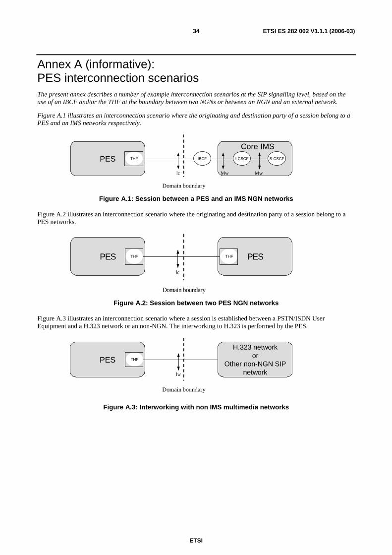
ETSI
ETSI ES 282 002 V1.1.1 (2006-03) 34
Annex A (informative): PES interconnection scenarios The present annex describes a number of example interconnection scenarios at the SIP signalling level, based on the use of an IBCF and/or the THF at the boundary between two NGNs or between an NGN and an external network.
Figure A.1 illustrates an interconnection scenario where the originating and destination party of a session belong to a PES and an IMS networks respectively.
PES IBCF S-CSCFI-CSCF
lc Mw Mw
THF
Core IMS
Domain boundary
Figure A.1: Session between a PES and an IMS NGN networks
Figure A.2 illustrates an interconnection scenario where the originating and destination party of a session belong to a PES networks.
PES PES
lc
THF THF
Domain boundary
Figure A.2: Session between two PES NGN networks
Figure A.3 illustrates an interconnection scenario where a session is established between a PSTN/ISDN User Equipment and a H.323 network or an non-NGN. The interworking to H.323 is performed by the PES.
PES
H.323 networkor
Other non-NGN SIPnetworklw
THF
Domain boundary
Figure A.3: Interworking with non IMS multimedia networks

ETSI
ETSI ES 282 002 V1.1.1 (2006-03) 35
Annex B (informative): Bibliography ETSI DTS/TISPAN-03048-EMTEL: "Telecommunications and Internet converged Services and Protocols for Advanced Networking (TISPAN); Analysis of Location Information produced by various SDOs".

ETSI
ETSI ES 282 002 V1.1.1 (2006-03) 36
History
Document history
V1.1.1 January 2006 Membership Approval Procedure MV 20060324: 2006-01-24 to 2006-03-24
V1.1.1 March 2006 Publication