es3510ma-dc 8-port layer 2 installation guide (ig).pdf · rfi emission: limit class a ... field...
TRANSCRIPT

Installation Guide
www.edge-core.com
ES3510MA-DC8-Port Layer 2Fast Ethernet Switch


INSTALLATION GUIDE
ES3510MA-DC FAST ETHERNET SWITCH
Layer 2 Switchwith 8 10/100BASE-T (RJ-45) Ports,and 2 Gigabit Combination Ports (RJ-45/SFP)
ES3510MA-DCE012011-CS-R01150200000250A


COMPLIANCES AND SAFETY STATEMENTS
FCC - CLASS AThis equipment has been tested and found to comply with the limits for a Class A digital device, pursuant to part 15 of the FCC Rules. These limits are designed to provide reasonable protection against harmful interference when the equipment is operated in a commercial environment. This equipment generates, uses, and can radiate radio frequency energy and, if not installed and used in accordance with the instruction manual, may cause harmful interference to radio communications. Operation of this equipment in a residential area is likely to cause harmful interference in which case the user will be required to correct the interference at his own expense.
You are cautioned that changes or modifications not expressly approved by the party responsible for compliance could void your authority to operate the equipment.
You may use unshielded twisted-pair (UTP) for RJ-45 connections - Category 3 or better for 10 Mbps connections, Category 5 or better for 100 Mbps connections, Category 5, 5e, or 6 for 1000 Mbps connections. For fiber optic connections, you may use 50/125 or 62.5/125 micron multimode fiber or 9/125 micron single-mode fiber.
– 5 –

COMPLIANCES AND SAFETY STATEMENTS
CE MARK DECLARATION OF CONFORMANCE FOR EMI AND SAFETY (EEC)This information technology equipment complies with the requirements of the Council Directive 89/336/EEC on the Approximation of the laws of the Member States relating to Electromagnetic Compatibility and 73/23/EEC for electrical equipment used within certain voltage limits and the Amendment Directive 93/68/EEC. For the evaluation of the compliance with these Directives, the following standards were applied:
RFI Emission: ◆ Limit class A according to EN 55022
◆ Limit class A for harmonic current emission according to EN 61000-3-2
◆ Limitation of voltage fluctuation and flicker in low-voltage supply system according to EN 61000-3-3
Immunity: ◆ Product family standard according to EN 55024
◆ Electrostatic Discharge according to EN 61000-4-2
◆ Radio-frequency electromagnetic field according to EN 61000-4-3
◆ Electrical fast transient/burst according to EN 61000-4-4
◆ Surge immunity test according to EN 61000-4-5
◆ Immunity to conducted disturbances, Induced by radio-frequency fields: EN 61000-4-6
◆ Power frequency magnetic field immunity test according to EN 61000-4-8
◆ Voltage dips, short interruptions and voltage variations immunity test according to EN 61000-4-11
LVD: ◆ EN 60950-1:2006
– 6 –

COMPLIANCES AND SAFETY STATEMENTS
SAFETY COMPLIANCEWarning: Fiber Optic Port Safety
Avertissment: Ports pour fibres optiques - sécurité sur le plan optique
Warnhinweis: Faseroptikanschlüsse - Optische Sicherheit
PSE ALARM本製品に同梱いたしております電源コードセットは、
本製品専用です。本電源コードセットは、本製品以外の
製品並びに他の用途でご使用いただくことは出来ません。
製品本体に同梱された電源コードセットを利用し、他製品
の電源コードセットを使用しないで下さい。
When using a fiber optic port, never look at the transmit laser while it is powered on. Also, never look directly at the fiber TX port and fiber cable ends when they are powered on.
Ne regardez jamais le laser tant qu'il est sous tension. Ne regardez jamais directement le port TX (Transmission) à fibres optiques et les embouts de câbles à fibres optiques tant qu'ils sont sous tension.
Niemals ein Übertragungslaser betrachten, während dieses eingeschaltet ist. Niemals direkt auf den Faser-TX-Anschluß und auf die Faserkabelenden schauen, während diese eingeschaltet sind.
CLASS I
LASER DEVICE
DISPOSITIF LASER
DE CLASSE I
LASERGER
DER KLASSE I
ÄT
– 7 –

COMPLIANCES AND SAFETY STATEMENTS
WARNINGS AND CAUTIONARY MESSAGES
ENVIRONMENTAL STATEMENTSThe manufacturer of this product endeavours to sustain an environmentally-friendly policy throughout the entire production process. This is achieved though the following means:
◆ Adherence to national legislation and regulations on environmental production standards.
◆ Conservation of operational resources.
◆ Waste reduction and safe disposal of all harmful un-recyclable by-products.
◆ Recycling of all reusable waste content.
◆ Design of products to maximize recyclables at the end of the product’s life span.
◆ Continual monitoring of safety standards.
WARNING: This product does not contain any serviceable user parts.
WARNING: Installation and removal of the unit must be carried out by qualified personnel only.
WARNING: When connecting this device to a power outlet, connect the field ground lead on the tri-pole power plug to a valid earth ground line to prevent electrical hazards.
WARNING: This switch uses lasers to transmit signals over fiber optic cable. The lasers are compliant with the requirements of a Class 1 Laser Product and are inherently eye safe in normal operation. However, you should never look directly at a transmit port when it is powered on.
CAUTION: Wear an anti-static wrist strap or take other suitable measures to prevent electrostatic discharge when handling this equipment.
CAUTION: Do not plug a phone jack connector in the RJ-45 port. This may damage this device.
CAUTION: Use only twisted-pair cables with RJ-45 connectors that conform to FCC standards.
– 8 –

COMPLIANCES AND SAFETY STATEMENTS
END OF PRODUCT LIFE SPANThis product is manufactured in such a way as to allow for the recovery and disposal of all included electrical components once the product has reached the end of its life.
MANUFACTURING MATERIALSThere are no hazardous nor ozone-depleting materials in this product.
DOCUMENTATIONAll printed documentation for this product uses biodegradable paper that originates from sustained and managed forests. The inks used in the printing process are non-toxic.
– 9 –

COMPLIANCES AND SAFETY STATEMENTS
– 10 –

ABOUT THIS GUIDE
PURPOSEThis guide details the hardware features of the switch, including the physical and performance-related characteristics, and how to install the switch.
AUDIENCEThe guide is intended for use by network administrators who are responsible for installing and setting up network equipment; consequently, it assumes a basic working knowledge of LANs (Local Area Networks).
CONVENTIONSThe following conventions are used throughout this guide to show information:
RELATED PUBLICATIONSThe following publication gives specific information on how to operate and use the management functions of the switch:
The Management Guide
Also, as part of the switch’s software, there is an online web-based help that describes all management related features.
NOTE: Emphasizes important information or calls your attention to related features or instructions.
CAUTION: Alerts you to a potential hazard that could cause loss of data, or damage the system or equipment.
WARNING: Alerts you to a potential hazard that could cause personal injury.
– 11 –

ABOUT THIS GUIDE
REVISION HISTORYThis section summarizes the changes in each revision of this guide.
JANUARY 2011 REVISIONThis is the first revision of this guide.
– 12 –

CONTENTS
COMPLIANCES AND SAFETY STATEMENTS 5
ABOUT THIS GUIDE 11
CONTENTS 13
TABLES 15
FIGURES 17
1 INTRODUCTION 19
Overview 19
Description of Hardware 21
2 NETWORK PLANNING 25
Introduction to Switching 25
Application Examples 26
Application Notes 30
3 INSTALLING THE SWITCH 31
Selecting a Site 31
Ethernet Cabling 32
Equipment Checklist 33
Mounting 33
Installing an Optional SFP Transceiver 35
Connecting to a Power Source 36
Connecting to the Console Port 38
4 MAKING NETWORK CONNECTIONS 41
Connecting Network Devices 41
Twisted-Pair Devices 41
– 13 –

CONTENTS
Fiber Optic SFP Devices 43
Connectivity Rules 45
Cable Labeling and Connection Records 47
A TROUBLESHOOTING 49
Diagnosing Switch Indicators 49
Power and Cooling Problems 50
Installation 50
In-Band Access 50
B CABLES 51
Twisted-Pair Cable and Pin Assignments 51
Fiber Standards 55
C SPECIFICATIONS 57
Physical Characteristics 57
Switch Features 58
Management Features 59
Standards 59
Compliances 60
GLOSSARY 61
INDEX 67
– 14 –

TABLES
Table 1: Supported SFP Transceivers 21
Table 2: 10/100 Mbps Port Status LEDs (1~8) 23
Table 3: 1000 Mbps Port Status LEDs (9~10) 23
Table 4: System Status LEDs 23
Table 5: Serial Cable Wiring 39
Table 6: Maximum 1000BASE-T Gigabit Ethernet Cable Length 45
Table 7: Maximum 1000BASE-SX Gigabit Ethernet Cable Lengths 45
Table 8: Maximum 1000BASE-LX Gigabit Ethernet Cable Length 46
Table 9: Maximum 1000BASE-LH Gigabit Ethernet Cable Length 46
Table 10: Maximum Fast Ethernet Cable Lengths 46
Table 11: Maximum Ethernet Cable Length 46
Table 12: Troubleshooting Chart 49
Table 13: 10/100BASE-TX MDI and MDI-X Port Pinouts 52
Table 14: 1000BASE-T MDI and MDI-X Port Pinouts 54
Table 15: Fiber Standards 55
– 15 –

TABLES
– 16 –
FIGURES
Figure 1: Front Panel 19
Figure 2: Rear Panel 20
Figure 3: Port LEDs 22
Figure 4: Power Supply Connector 24
Figure 5: Collapsed Backbone 26
Figure 6: Network Aggregation Plan 27
Figure 7: Remote Connections with Fiber Cable 28
Figure 8: Making VLAN Connections 29
Figure 9: RJ-45 Connections 32
Figure 10: Attaching the Adhesive Feet 34
Figure 11: Inserting an SFP Transceiver into a Slot 35
Figure 12: DC Power Supply Connector 36
Figure 13: DC Plug Connections 37
Figure 14: Console Cable 38
Figure 15: Making Twisted-Pair Connections 42
Figure 16: Making Fiber Port Connections 44
Figure 17: RJ-45 Connector Pin Numbers 51
Figure 18: Straight-through Wiring 53
Figure 19: Crossover Wiring 53
– 17 –

FIGURES
– 18 –

1 INTRODUCTION
OVERVIEW
The ES3510MA-DC is a Fast Ethernet Layer 2 switch with 8 100BASE-TX ports, and two combination 1000BASE-T ports: RJ-45 ports and Small Form Factor Pluggable (SFP) transceiver slots1. The switch also includes an SNMP-based management agent, which provides both in-band and out-of-band access for managing the switch.
The ES3510MA-DC provides a broad range of powerful features for Layer 2 switching, delivering reliability and consistent performance for your network traffic. It brings order to poorly performing networks by segregating them into separate broadcast domains with IEEE 802.1Q compliant VLANs, and empowers multimedia applications with multicast switching and CoS services.
Figure 1: Front Panel
1. If an SFP transceiver is plugged in, the corresponding RJ-45 port is disabled for ports 9-10.
Port Status Indicators
1000BASE-T/SFP Combination Ports
System Indicators Console Port
100 Mbps RJ-45 Ports
– 19 –

CHAPTER 1 | IntroductionOverview
Figure 2: Rear Panel
SWITCH ARCHITECTUREThe switch employs a wire-speed, non-blocking switching fabric. This permits simultaneous wire-speed transport of multiple packets at low latency on all ports. The switch also features full-duplex capability on all ports, which effectively doubles the bandwidth of each connection.
This switch uses store-and-forward switching to ensure maximum data integrity. With store-and-forward switching, the entire packet must be received into a buffer and checked for validity before being forwarded. This prevents errors from being propagated throughout the network.
NETWORK MANAGEMENT OPTIONSWith a comprehensive array of LEDs, the switch provides “at a glance” monitoring of network and port status. The switch can be managed over the network with a web browser or Telnet application, or via a direct connection to the console port. The switch includes a built-in network management agent that allows it to be managed in-band using SNMP or RMON (Groups 1, 2, 3, 9) protocols. It also has an RS-232 serial port (DB-9 connector) on the front panel for out-of-band management. A PC may be connected to this port for configuration and monitoring out-of-band via a null-modem serial cable.
For a detailed description of the management features, refer to the Management Guide.
Power Connector
– 20 –

CHAPTER 1 | IntroductionDescription of Hardware
DESCRIPTION OF HARDWARE
RJ-45 PORTSThe switch contains 8 100BASE-TX RJ-45 ports and 2 shared 1000BASE-T RJ-45/SFP ports. All RJ-45 ports support automatic MDI/MDI-X operation, so you can use straight-through cables for all network connections to PCs or servers, or to other switches or hubs. (See “1000BASE-T Pin Assignments” on page 54.)
Each of these ports support auto-negotiation, so the optimum transmission mode (half or full duplex), and data rate (10, or 100 Mbps - ports 1~8, and 10, 100, or 1000 - ports 9~10) can be selected automatically2.
Each port also supports IEEE 802.3x auto-negotiation of flow control, so the switch can automatically prevent port buffers from becoming saturated.
SFP TRANSCEIVER SLOTSThe Small Form Factor Pluggable (SFP) transceiver slots are shared with the two 1000BASE-T RJ-45 ports (ports 9~10). In the default configuration, if an SFP transceiver (purchased separately) is installed in a slot and has a valid link on the port, the associated RJ-45 port is disabled. The switch can also be configured to force the use of an RJ-45 port or SFP slot, as required.
The following “table” shows a list of transceiver types which have been tested with the switch. For an updated list of vendors supplying these transceivers, contact your local dealer. For information on the recommended standards for fiber optic cabling, see “1000 Mbps Gigabit Ethernet Collision Domain” on page 45.
2. The 1000BASE-T standard does not support forced mode. Auto-negotiation must always be used to establish a connection over any 1000BASE-T port or trunk.
Table 1: Supported SFP Transceivers
Media Standard Cable Diameter (microns)
Wavelength (nm) Maximum Distance*
1000BASE-SX 50/125 850 550 m
62.5/125 850 400 m
– 21 –

CHAPTER 1 | IntroductionDescription of Hardware
PORT AND SYSTEM STATUS LEDS The switch includes a display panel for key system and port indications that simplify installation and network troubleshooting. The LEDs, which are located on the front panel for easy viewing, are shown below and described in the following tables.
Figure 3: Port LEDs
1000BASE-LX 50/125 1300 550 m
62.5/125 1300 550 m
9/125 1300 10 km
1000BASE-LH 9/125 1310 35 km
1550 80 km
1000BASE-T 100 m
* Maximum distance may vary for different SFP vendors.
Table 1: Supported SFP Transceivers (Continued)
Media Standard Cable Diameter (microns)
Wavelength (nm) Maximum Distance*
Port Status LEDsSystem Status LEDs
– 22 –

CHAPTER 1 | IntroductionDescription of Hardware
Table 2: 10/100 Mbps Port Status LEDs (1~8)
LED Condition Status
(Link/Activity) On/Flashing Green Port has established a valid 10/100 Mbps network connection. Flashing indicates activity.
Off There is no valid link on the port.
Table 3: 1000 Mbps Port Status LEDs (9~10)
LED Condition Status
(Link/Activity) On/Flashing Green Port has established a valid 1000 Mbps network connection. Flashing indicates activity.
On/Flashing Amber Port has established a valid 10/100 Mbps network connection. Flashing indicates activity.
Off There is no valid link on the port.
Table 4: System Status LEDs
LED Condition Status
Power On Green The unit’s internal power supply is operating normally.
On Amber The unit has an internal power supply fault.
Off The unit has no power connected.
Diag On Green The system diagnostic test has completed successfully.
Flashing Green The system diagnostic test is in progress.
On Amber The system diagnostic test has detected a fault.
– 23 –

CHAPTER 1 | IntroductionDescription of Hardware
POWER SUPPLY CONNECTORThere is one DC power connector on the rear panel of the switch. The power connector is for connection to a 48 VDC supply circuit.
Figure 4: Power Supply Connector
– 24 –

2 NETWORK PLANNING
INTRODUCTION TO SWITCHING
A network switch allows simultaneous transmission of multiple packets via non-crossbar switching. This means that it can partition a network more efficiently than bridges or routers. The switch has, therefore, been recognized as one of the most important building blocks for today’s networking technology.
When performance bottlenecks are caused by congestion at the network access point (such as the network card for a high-volume file server), the device experiencing congestion (server, power user, or hub) can be attached directly to a switched port. And, by using full-duplex mode, the bandwidth of the dedicated segment can be doubled to maximize throughput.
When networks are based on repeater (hub) technology, the distance between end stations is limited by a maximum hop count. However, a switch turns the hop count back to zero. So subdividing the network into smaller and more manageable segments, and linking them to the larger network by means of a switch, removes this limitation.
A switch can be easily configured in any Ethernet, Fast Ethernet, or Gigabit Ethernet network to significantly boost bandwidth while using conventional cabling and network cards.
– 25 –

CHAPTER 2 | Network PlanningApplication Examples
APPLICATION EXAMPLES
The switch is not only designed to segment your network, but also to provide a wide range of options in setting up network connections. Some typical applications are described below.
COLLAPSED BACKBONEThe switch is an excellent choice for mixed Ethernet, Fast Ethernet, and Gigabit Ethernet installations where significant growth is expected in the near future. You can easily build on this basic configuration, adding direct full-duplex connections to workstations or servers. When the time comes for further expansion, just connect to another hub or switch using one of the Fast Ethernet ports built into the front panel or a Gigabit Ethernet port on a plug-in SFP transceiver.
In the figure below, the switch is operating as a collapsed backbone for a small LAN. It is providing dedicated 10 Mbps full-duplex connections to workstations, 100 Mbps full-duplex connections to power users, and 1 Gbps full-duplex connections to servers.
Figure 5: Collapsed Backbone
– 26 –

CHAPTER 2 | Network PlanningApplication Examples
NETWORK AGGREGATION PLANWith 10 parallel bridging ports (i.e., 10 distinct collision domains), the switch can collapse a complex network down into a single efficient bridged node, increasing overall bandwidth and throughput.
In the figure below, the 100BASE-TX ports on the switch are providing 100 Mbps connectivity for up to 8 segments. In addition, the switch is also connecting several servers at 1000 Mbps.
Figure 6: Network Aggregation Plan
– 27 –

CHAPTER 2 | Network PlanningApplication Examples
REMOTE CONNECTIONS WITH FIBER CABLEFiber optic technology allows for longer cabling than any other media type. A 1000BASE-SX (MMF) link can connect to a site up to 550 meters away, a 1000BASE-LX (SMF) link up to 10 km, and a 1000BASE-LH link up to 80 km. This allows the switch to serve as a collapsed backbone, providing direct connectivity for a widespread LAN.
The figure below illustrates the switch connecting multiple segments with fiber cable.
Figure 7: Remote Connections with Fiber Cable
– 28 –

CHAPTER 2 | Network PlanningApplication Examples
MAKING VLAN CONNECTIONSThis switch supports VLANs which can be used to organize any group of network nodes into separate broadcast domains. VLANs confine broadcast traffic to the originating group, and can eliminate broadcast storms in large networks. This provides a more secure and cleaner network environment.
VLANs can be based on untagged port groups, or traffic can be explicitly tagged to identify the VLAN group to which it belongs. Untagged VLANs can be used for small networks attached to a single switch. However, tagged VLANs should be used for larger networks, and all the VLANs assigned to the inter-switch links.
Figure 8: Making VLAN Connections
NOTE: When connecting to a switch that does not support IEEE 802.1Q VLAN tags, use untagged ports.
– 29 –

CHAPTER 2 | Network PlanningApplication Notes
APPLICATION NOTES
1. Full-duplex operation only applies to point-to-point access (such as when a switch is attached to a workstation, server or another switch). When the switch is connected to a hub, both devices must operate in half-duplex mode.
2. Avoid using flow control on a port connected to a hub unless it is actually required to solve a problem. Otherwise back pressure jamming signals may degrade overall performance for the segment attached to the hub.
3. Based on recommended standards, the length of fiber optic cable for a single switched link should not exceed:
■ 1000BASE-SX: 550 m (1805 ft) for multimode fiber.
■ 1000BASE-LX: 10 km (6.2 miles) for single-mode fiber.
■ 1000BASE-LH: 80 km (49.7 miles) for single-mode fiber.
However, power budget constraints must also be considered when calculating the maximum cable length for your specific environment.
– 30 –

3 INSTALLING THE SWITCH
SELECTING A SITE
Switch units can be mounted in a standard 19-inch equipment rack or on a flat surface. Be sure to follow the guidelines below when choosing a location.
◆ The site should:
■ be at the center of all the devices you want to link and near a power source.
■ be able to maintain its temperature within 0 to 45 °C (32 to 113 °F) and its humidity within 10% to 90%, non-condensing.
■ provide adequate space (approximately two inches) on all sides for proper air flow.
■ be accessible for installing, cabling and maintaining the devices.
■ allow the status LEDs to be clearly visible.
◆ Make sure twisted-pair cable is always routed away from power lines, fluorescent lighting fixtures and other sources of electrical interference, such as radios and transmitters.
◆ Make sure that the unit is connected to an independent grounded DC power circuit. Verify that the power requirements for the unit can be met as listed under “DC Input” on page 58.
– 31 –
CHAPTER 3 | Installing the SwitchEthernet Cabling
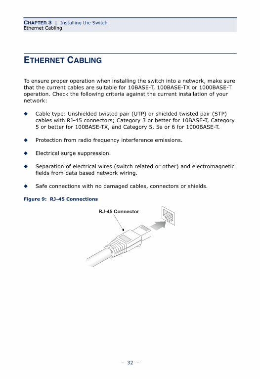
ETHERNET CABLING
To ensure proper operation when installing the switch into a network, make sure that the current cables are suitable for 10BASE-T, 100BASE-TX or 1000BASE-T operation. Check the following criteria against the current installation of your network:
◆ Cable type: Unshielded twisted pair (UTP) or shielded twisted pair (STP) cables with RJ-45 connectors; Category 3 or better for 10BASE-T, Category 5 or better for 100BASE-TX, and Category 5, 5e or 6 for 1000BASE-T.
◆ Protection from radio frequency interference emissions.
◆ Electrical surge suppression.
◆ Separation of electrical wires (switch related or other) and electromagnetic fields from data based network wiring.
◆ Safe connections with no damaged cables, connectors or shields.
Figure 9: RJ-45 Connections
RJ-45 Connector
– 32 –

CHAPTER 3 | Installing the SwitchEquipment Checklist
EQUIPMENT CHECKLIST
After unpacking this switch, check the contents to be sure you have received all the components. Then, before beginning the installation, be sure you have all other necessary installation equipment.
PACKAGE CONTENTS◆ Fast Ethernet Switch (ES3510MA-DC)
◆ Four adhesive foot pads
◆ Power Cord—either US, Continental Europe or UK
◆ RJ-45 to RS-232 console cable
◆ This Installation Guide
◆ Management Guide CD
MOUNTING
The switch can be mounted on a desktop or shelf. Mounting instructions follow.
DESKTOP OR SHELF MOUNTING1. Attach the four adhesive feet to the bottom of the first switch.
– 33 –

CHAPTER 3 | Installing the SwitchMounting
Figure 10: Attaching the Adhesive Feet
2. Set the device on a flat surface near an AC power source, making sure there are at least two inches of space on all sides for proper air flow.
3. If installing a single switch only, go to “Connecting to a Power Source” on page 36.
4. If installing multiple switches, attach four adhesive feet to each one. Place each device squarely on top of the one below, in any order.
– 34 –

CHAPTER 3 | Installing the SwitchInstalling an Optional SFP Transceiver
INSTALLING AN OPTIONAL SFP TRANSCEIVER
Figure 11: Inserting an SFP Transceiver into a Slot
The SFP slots support the following optional SFP transceivers:
◆ 1000BASE-SX
◆ 1000BASE-LX
◆ 1000BASE-LH
To install an SFP transceiver, do the following:
1. Consider network and cabling requirements to select an appropriate SFP transceiver type.
2. Insert the transceiver with the optical connector facing outward and the slot connector facing down. Note that SFP transceivers are keyed so they can only be installed in one orientation.
3. Slide the SFP transceiver into the slot until it clicks into place.
– 35 –

CHAPTER 3 | Installing the SwitchConnecting to a Power Source
CONNECTING TO A POWER SOURCE
An external 48 VDC power supply must be connected to the DC power connector on the rear panel of the switch.
Figure 12: DC Power Supply Connector
NOTE: SFP transceivers are hot-swappable. The switch does not need to be powered off before installing or removing a transceiver. However, always first disconnect the network cable before removing a transceiver.
NOTE: SFP transceivers are not provided in the switch package.
WARNING: Before wiring the DC plug or connecting power to the switch, ensure that power to the feed lines is turned off at the supply circuit breaker or disconnected from the power bus.
– 36 –

CHAPTER 3 | Installing the SwitchConnecting to a Power Source
To connect the switch to a power source:
1. Verify that the external DC power supply can provide 36 to 75 VDC, 0.373 A minimum.
2. Prepare two wires for the power source. Use 10 to 24 AWG stranded copper wire. Make sure these wires are not plugged into the power source.
3. Use a wire stripper to carefully strip about a half an inch of the outer insulation off the end of each wire, exposing the copper core.
4. Twist the copper wire strands together to form a tight braid. If possible, solder the exposed braid of wire together for better conductivity.
5. Connect the external power feed and power ground/return lines to the DC plug (provided with the switch). The power leads are labeled on the rear of the switch, above the DC power connection block. The 48 VDC power feed line connects to the “+” terminal, and the return line connects to the “-” terminal. Use a small flat-tip screwdriver to loosen the screws on the power plug and open the wire clamps.
Figure 13: DC Plug Connections
NOTE: To provide adequate circuit protection between the DC power supply and the switch, all intermediate wiring and circuitry should be rated to carry a load at least two times the maximum rating for this switch.
NOTE: The wiring between the DC power supply and the switch must be stranded copper wire within the range of 10 to 24 AWG.
NOTE: Wiring for the power input terminals on the switch are described below. Wiring of the DC power supply terminals depends on the equipment in use on the local site. The wiring should also be color coded according to local standards to ensure that the input power and ground lines can be easily distinguished.
48 VDC power feed
Ground
DC power return
– 37 –

CHAPTER 3 | Installing the SwitchConnecting to the Console Port
6. Insert the wire leads into the openings shown in the figure above. Each lead inserted in the power plug must match the lead attached to the power source. Use the labeling above the DC power connector to identify the appropriate power input and return or ground lines.
7. Tighten down each wire clamp screw securely. You should not be able to pull on a wire and dislodge it.
8. Insert the power plug into the power receptacle on the switch’s rear panel.
9. At the power source, turn on the power for the feed lines or power bus.
10. Check the Power LED indicator on the switch to verify that the power is on. If not, recheck the power supply and power cable connections at the supply source and at switch power connector.
CONNECTING TO THE CONSOLE PORT
This port is used to connect a console device to the switch through a serial cable. The console device can be a PC or workstation running a VT-100 terminal emulator, or a VT-100 terminal. A crossover RJ-45 to DB-9 cable is supplied with the unit for connecting to the console port, as illustrated below. The PIN assignments used to connect to the serial port are described below.
Figure 14: Console Cable
CAUTION: If the power leads are plugged into the wrong holes, the power supply will not work properly and may damage the switch.
RJ-45 ConnectorConsole Port
DB-9 Port
aaaaaaaaa
aaaaaaaaa
– 38 –

CHAPTER 3 | Installing the SwitchConnecting to the Console Port
WIRING MAP FOR SERIAL CABLE
The serial port’s configuration requirements are as follows:
◆ Default Baud rate—115,200 bps
◆ Character Size—8 Characters
◆ Parity—None
◆ Stop bit—One
◆ Data bits—8
◆ Flow control—none
Table 5: Serial Cable Wiring
Switch 8-PIN Serial Port Null Modem PC’s 9-PIN DTE Port
6 RXD (receive data) <----------------------- 3 TXD (transmit data)
3 TXD (transmit data) ------------------------> 2 RXD (receive data)
5 SGND (signal ground) -------------------------- 5 SGND (signal ground)
– 39 –

CHAPTER 3 | Installing the SwitchConnecting to the Console Port
– 40 –

4 MAKING NETWORK CONNECTIONS
CONNECTING NETWORK DEVICES
The switch is designed to be connected to 10 or 100 Mbps network cards in PCs and servers, as well as to other switches and hubs. It may also be connected to remote devices using optional 1000BASE-SX, 1000BASE-LX, or 1000BASE-LH SFP transceivers.
TWISTED-PAIR DEVICES
Each device requires an unshielded twisted-pair (UTP) cable with RJ-45 connectors at both ends. Use Category 5, 5e or 6 cable for 1000BASE-T connections, Category 5 or better for 100BASE-TX connections, and Category 3 or better for 10BASE-T connections.
CABLING GUIDELINESThe RJ-45 ports on the switch support automatic MDI/MDI-X pinout configuration, so you can use standard straight-through twisted-pair cables to connect to any other network device (PCs, servers, switches, routers, or hubs).
See Appendix B for further information on cabling.
CAUTION: Do not plug a phone jack connector into an RJ-45 port. This will damage the switch. Use only twisted-pair cables with RJ-45 connectors that conform to FCC standards.
– 41 –

CHAPTER 4 | Making Network ConnectionsTwisted-Pair Devices
CONNECTING TO PCS, SERVERS, HUBS AND SWITCHES1. Attach one end of a twisted-pair cable segment to the device’s RJ-45
connector.
Figure 15: Making Twisted-Pair Connections
2. If the device is a network card and the switch is in the wiring closet, attach the other end of the cable segment to a modular wall outlet that is connected to the wiring closet. Otherwise, attach the other end to an available port on the switch.
Make sure each twisted pair cable does not exceed 100 meters (328 ft) in length.
3. As each connection is made, the Link LED (on the switch) corresponding to each port will light green or amber to indicate that the connection is valid.
NOTE: Avoid using flow control on a port connected to a hub unless it is actually required to solve a problem. Otherwise back pressure jamming signals may degrade overall performance for the segment attached to the hub.
– 42 –

CHAPTER 4 | Making Network ConnectionsFiber Optic SFP Devices
FIBER OPTIC SFP DEVICES
An optional Gigabit SFP transceiver (1000BASE-SX, 1000BASE-LX or 1000BASE-LH) can be used for a backbone connection between switches, or for connecting to a high-speed server.
Each single-mode fiber port requires 9/125 micron single-mode fiber optic cable with an LC connector at both ends. Each multimode fiber optic port requires 50/125 or 62.5/125 micron multimode fiber optic cabling with an LC connector at both ends.
1. Remove and keep the LC port’s rubber plug. When not connected to a fiber cable, the rubber plug should be replaced to protect the optics.
2. Check that the fiber terminators are clean. You can clean the cable plugs by wiping them gently with a clean tissue or cotton ball moistened with a little ethanol. Dirty fiber terminators on fiber optic cables will impair the quality of the light transmitted through the cable and lead to degraded performance on the port.
3. Connect one end of the cable to the LC port on the switch and the other end to the LC port on the other device. Since LC connectors are keyed, the cable can be attached in only one orientation.
WARNING: This switch uses lasers to transmit signals over fiber optic cable. The lasers are compliant with the requirements of a Class 1 Laser Product and are inherently eye safe in normal operation. However, you should never look directly at a transmit port when it is powered on.
WARNING: When selecting a fiber SFP device, considering safety, please make sure that it can function at a temperature that is not less than the recommended maximum operational temperature of the product. You must also use an approved Laser Class 1 SFP transceiver.
– 43 –

CHAPTER 4 | Making Network ConnectionsFiber Optic SFP Devices
Figure 16: Making Fiber Port Connections
4. As a connection is made, check the Link LED on the switch corresponding to the port to be sure that the connection is valid.
The 1000BASE-SX, 1000BASE-LX, 1000BASE-LH fiber optic ports operate at 1 Gbps, full duplex, with auto-negotiation of flow control. The maximum length for fiber optic cable operating at Gigabit speed will depend on the fiber type as listed under “1000 Mbps Gigabit Ethernet Collision Domain” on page 45.
– 44 –

CHAPTER 4 | Making Network ConnectionsConnectivity Rules
CONNECTIVITY RULES
When adding hubs (repeaters) to your network, please follow the connectivity rules listed in the manuals for these products. However, note that because switches break up the path for connected devices into separate collision domains, you should not include the switch or connected cabling in your calculations for cascade length involving other devices.
1000BASE-T CABLE REQUIREMENTSAll Category 5 UTP cables that are used for 100BASE-TX connections should also work for 1000BASE-T, providing that all four wire pairs are connected. However, it is recommended that for all critical connections, or any new cable installations, Category 5e (enhanced Category 5) or Category 6 cable should be used. The Category 5e and 6 specifications include test parameters that are only recommendations for Category 5. Therefore, the first step in preparing existing Category 5 cabling for running 1000BASE-T is a simple test of the cable installation to be sure that it complies with the IEEE 802.3-2005 standards.
1000 MBPS GIGABIT ETHERNET COLLISION DOMAIN
Table 6: Maximum 1000BASE-T Gigabit Ethernet Cable Length
Cable Type Maximum Cable Length Connector
Category 5, 5e, or 6 100-ohm UTP or STP 100 m (328 ft) RJ-45
Table 7: Maximum 1000BASE-SX Gigabit Ethernet Cable Lengths
Fiber Size Fiber Bandwidth Maximum Cable Length Connector
62.5/125 micron multimode fiber
160 MHz/km 2-220 m (7-722 ft) LC
200 MHz/km 2-275 m (7-902 ft) LC
50/125 micron multimode fiber
400 MHz/km 2-500 m (7-1641 ft) LC
500 MHz/km 2-550 m (7-1805 ft) LC
– 45 –

CHAPTER 4 | Making Network ConnectionsConnectivity Rules
100 MBPS FAST ETHERNET COLLISION DOMAIN
10 MBPS ETHERNET COLLISION DOMAIN
Table 8: Maximum 1000BASE-LX Gigabit Ethernet Cable Length
Fiber Size Fiber Bandwidth Maximum Cable Length Connector
9/125 micron single-mode fiber
N/A 2 m - 10 km (7 ft - 6.2 miles) LC
Table 9: Maximum 1000BASE-LH Gigabit Ethernet Cable Length
Fiber Size Fiber Bandwidth Maximum Cable Length Connector
9/125 micron single-mode fiber
N/A 2 m - 80 km (7 ft - 49.7 miles)
LC
Table 10: Maximum Fast Ethernet Cable Lengths
Type Cable Type Max. Cable Length Connector
100BASE-TX Category 5 or better 100-ohm UTP or STP
100 m (328 ft) RJ-45
Table 11: Maximum Ethernet Cable Length
Type Cable Type Max. Cable Length Connector
10BASE-T Category 3 or better 100-ohm UTP 100 m (328 ft) RJ-45
– 46 –

CHAPTER 4 | Making Network ConnectionsCable Labeling and Connection Records
CABLE LABELING AND CONNECTION RECORDS
When planning a network installation, it is essential to label the opposing ends of cables and to record where each cable is connected. Doing so will enable you to easily locate inter-connected devices, isolate faults and change your topology without need for unnecessary time consumption.
To best manage the physical implementations of your network, follow these guidelines:
◆ Clearly label the opposing ends of each cable.
◆ Using your building’s floor plans, draw a map of the location of all network-connected equipment. For each piece of equipment, identify the devices to which it is connected.
◆ Note the length of each cable and the maximum cable length supported by the switch ports.
◆ For ease of understanding, use a location-based key when assigning prefixes to your cable labeling.
◆ Use sequential numbers for cables that originate from the same equipment.
◆ Differentiate between racks by naming accordingly.
◆ Label each separate piece of equipment.
◆ Display a copy of your equipment map, including keys to all abbreviations at each equipment rack.
– 47 –

CHAPTER 4 | Making Network ConnectionsCable Labeling and Connection Records
– 48 –

A TROUBLESHOOTING
DIAGNOSING SWITCH INDICATORS
Table 12: Troubleshooting Chart
Symptom Action
Power LED is Off ◆ Check connections between the switch and the DC power supply.
◆ Contact your dealer for assistance.
Power LED is On Amber ◆ Contact your local dealer for assistance.
DIAG LED is On Amber ◆ Power cycle the switch to try and clear the condition.
◆ If the condition does not clear, contact your dealer for assistance.
Link LED is Off ◆ Verify that the switch and attached device are powered on.
◆ Be sure the cable is plugged into both the switch and corresponding device.
◆ If the switch is installed in a rack, check the connections to the punch-down block and patch panel.
◆ Verify that the proper cable type is used and its length does not exceed specified limits.
◆ Check the adapter on the attached device and cable connections for possible defects. Replace the defective adapter or cable if necessary.
– 49 –

APPENDIX A | TroubleshootingPower and Cooling Problems
POWER AND COOLING PROBLEMS
If the power indicator does not turn on when the power cord is plugged in, you may have a problem with the power outlet, power cord, or internal power supply. However, if the unit powers off after running for a while, check for loose power connections, power losses or surges at the power outlet. If you still cannot isolate the problem, the internal power supply may be defective.
INSTALLATION
Verify that all system components have been properly installed. If one or more components appear to be malfunctioning (such as the power cord or network cabling), test them in an alternate environment where you are sure that all the other components are functioning properly.
IN-BAND ACCESS
You can access the management agent in the switch from anywhere within the attached network using Telnet, a web browser, or other network management software tools. However, you must first configure the switch with a valid IP address, subnet mask, and default gateway. If you have trouble establishing a link to the management agent, check to see if you have a valid network connection. Then verify that you entered the correct IP address. Also, be sure the port through which you are connecting to the switch has not been disabled. If it has not been disabled, then check the network cabling that runs between your remote location and the switch.
NOTE: The management agent accepts up to four simultaneous Telnet sessions. If the maximum number of sessions already exists, an additional Telnet connection will not be able to log into the system.
– 50 –

B CABLES
TWISTED-PAIR CABLE AND PIN ASSIGNMENTS
For 10/100BASE-TX connections, the twisted-pair cable must have two pairs of wires. For 1000BASE-T connections the twisted-pair cable must have four pairs of wires. Each wire pair is identified by two different colors. For example, one wire might be green and the other, green with white stripes. Also, an RJ-45 connector must be attached to both ends of the cable.
The figure below illustrates how the pins on the RJ-45 connector are numbered. Be sure to hold the connectors in the same orientation when attaching the wires to the pins.
Figure 17: RJ-45 Connector Pin Numbers
CAUTION: DO NOT plug a phone jack connector into any RJ-45 port. Use only twisted-pair cables with RJ-45 connectors that conform with FCC standards.
CAUTION: Each wire pair must be attached to the RJ-45 connectors in a specific orientation.
811
8
– 51 –

APPENDIX B | CablesTwisted-Pair Cable and Pin Assignments
10BASE-T/100BASE-TX PIN ASSIGNMENTSUse unshielded twisted-pair (UTP) or shielded twisted-pair (STP) cable for RJ-45 connections: 100-ohm Category 3 or better cable for 10 Mbps connections, or 100-ohm Category 5 or better cable for 100 Mbps connections. Also be sure that the length of any twisted-pair connection does not exceed 100 meters (328 feet).
The RJ-45 ports on the switch base unit support automatic MDI/MDI-X operation, so you can use straight-through cables for all network connections to PCs or servers, or to other switches or hubs. In straight-through cable, pins 1, 2, 3, and 6, at one end of the cable, are connected straight through to pins 1, 2, 3, and 6 at the other end of the cable. When using any RJ-45 port on this switch, you can use either straight-through or crossover cable.
Note: The “+” and “-” signs represent the polarity of the wires that make up each wire pair.
STRAIGHT-THROUGH WIRINGIf the twisted-pair cable is to join two ports and only one of the ports has an internal crossover (MDI-X), the two pairs of wires must be straight-through. (When auto-negotiation is enabled for any RJ-45 port on this switch, you can use either straight-through or crossover cable to connect to any device type.)
You must connect all four wire pairs as shown in the following diagram to support Gigabit Ethernet.
Table 13: 10/100BASE-TX MDI and MDI-X Port Pinouts
Pin MDI Signal Name MDI-X Signal Name
1 Transmit Data plus (TD+) Receive Data plus (RD+)
2 Transmit Data minus (TD-) Receive Data minus (RD-)
3 Receive Data plus (RD+) Transmit Data plus (TD+)
6 Receive Data minus (RD-) Transmit Data minus (TD-)
4,5,7,8 Not used Not used
– 52 –

APPENDIX B | CablesTwisted-Pair Cable and Pin Assignments
Figure 18: Straight-through Wiring
CROSSOVER WIRINGIf the twisted-pair cable is to join two ports and either both ports are labeled with an “X” (MDI-X) or neither port is labeled with an “X” (MDI), a crossover must be implemented in the wiring. (When auto-negotiation is enabled for any RJ-45 port on this switch, you can use either straight-through or crossover cable to connect to any device type.)
You must connect all four wire pairs as shown in the following diagram to support Gigabit Ethernet.
Figure 19: Crossover Wiring
White/Orange Stripe
Orange
White/Green Stripe
Green
1
2
3
4
5
6
7
8
1
2
3
4
5
6
7
8
EIA/TIA 568B RJ-45 Wiring Standard
10/100BASE-TX Straight-through Cable
End A End BBlue
White/Blue Stripe
Brown
White/Brown Stripe
White/Orange Stripe
Orange
White/Green Stripe1
2
3
4
5
6
7
8
1
2
3
4
5
6
7
8
EIA/TIA 568B RJ-45 Wiring Standard
10/100BASE-TX Crossover Cable
End A End B
Green
Blue
White/Blue Stripe
Brown
White/Brown Stripe
– 53 –
APPENDIX B | CablesTwisted-Pair Cable and Pin Assignments
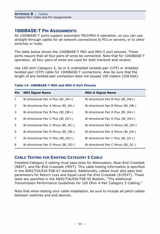
1000BASE-T PIN ASSIGNMENTSAll 1000BASE-T ports support automatic MDI/MDI-X operation, so you can use straight-through cables for all network connections to PCs or servers, or to other switches or hubs.
The table below shows the 1000BASE-T MDI and MDI-X port pinouts. These ports require that all four pairs of wires be connected. Note that for 1000BASE-T operation, all four pairs of wires are used for both transmit and receive.
Use 100-ohm Category 5, 5e or 6 unshielded twisted-pair (UTP) or shielded twisted-pair (STP) cable for 1000BASE-T connections. Also be sure that the length of any twisted-pair connection does not exceed 100 meters (328 feet).
CABLE TESTING FOR EXISTING CATEGORY 5 CABLE
Installed Category 5 cabling must pass tests for Attenuation, Near-End Crosstalk (NEXT), and Far-End Crosstalk (FEXT). This cable testing information is specified in the ANSI/TIA/EIA-TSB-67 standard. Additionally, cables must also pass test parameters for Return Loss and Equal-Level Far-End Crosstalk (ELFEXT). These tests are specified in the ANSI/TIA/EIA-TSB-95 Bulletin, “The Additional Transmission Performance Guidelines for 100 Ohm 4-Pair Category 5 Cabling.”
Note that when testing your cable installation, be sure to include all patch cables between switches and end devices.
Table 14: 1000BASE-T MDI and MDI-X Port Pinouts
Pin MDI Signal Name MDI-X Signal Name
1 Bi-directional Pair A Plus (BI_DA+) Bi-directional Pair B Plus (BI_DB+)
2 Bi-directional Pair A Minus (BI_DA-) Bi-directional Pair B Minus (BI_DB-)
3 Bi-directional Pair B Plus (BI_DB+) Bi-directional Pair A Plus (BI_DA+)
4 Bi-directional Pair C Plus (BI_DC+) Bi-directional Pair D Plus (BI_DD+)
5 Bi-directional Pair C Minus (BI_DC-) Bi-directional Pair D Minus (BI_DD-)
6 Bi-directional Pair B Minus (BI_DB-) Bi-directional Pair A Minus (BI_DA-)
7 Bi-directional Pair D Plus (BI_DD+) Bi-directional Pair C Plus (BI_DC+)
8 Bi-directional Pair D Minus (BI_DD-) Bi-directional Pair C Minus (BI_DC-)
– 54 –

APPENDIX B | CablesFiber Standards
ADJUSTING EXISTING CATEGORY 5 CABLING TO RUN 1000BASE-TIf your existing Category 5 installation does not meet one of the test parameters for 1000BASE-T, there are basically three measures that can be applied to try and correct the problem:
1. Replace any Category 5 patch cables with high-performance Category 5e or Category 6 cables.
2. Reduce the number of connectors used in the link.
3. Reconnect some of the connectors in the link.
FIBER STANDARDS
The International Telecommunication Union (ITU-T) has standardized various fiber types for data networks. These are summarized in the following table.
Table 15: Fiber Standards
ITU-T Standard
Description Application
G.651 Multimode Fiber50/125-micron core
Short-reach connections in the 1300-nm or 850-nm band
G.652 Non-Dispersion-Shifted FiberSingle-mode, 9/125-micron core
Longer spans and extended reach. Optimized for operation in the 1310-nm band. but can also be used in the 1550-nm band
G.652.C Low Water Peak Non-Dispersion-Shifted FiberSingle-mode, 9/125-micron core
Longer spans and extended reach. Optimized for wavelength-division multiplexing (WDM) transmission across wavelengths from 1285 to 1625 nm. The zero dispersion wavelength is in the 1310-nm region.
G.653 Dispersion-Shifted FiberSingle-mode, 9/125-micron core
Longer spans and extended reach. Optimized for operation in the region from 1500 to 1600-nm.
– 55 –

APPENDIX B | CablesFiber Standards
G.654 1550-nm Loss-Minimized FiberSingle-mode, 9/125-micron core
Extended long-haul applications. Optimized for high-power transmission in the 1500 to 1600-nm region, with low loss in the 1550-nm band.
G.655 Non-Zero Dispersion-Shifted FiberSingle-mode, 9/125-micron core
Extended long-haul applications. Optimized for high-power dense wavelength-division multiplexing (DWDM) operation in the region from 1500 to 1600-nm.
Table 15: Fiber Standards (Continued)
ITU-T Standard
Description Application
– 56 –

C SPECIFICATIONS
PHYSICAL CHARACTERISTICS
PORTS8 10/100BASE-TX, with auto-negotiation2 10/100/1000BASE-T, shared with two SFP transceiver slots
NETWORK INTERFACEPorts 1-10: RJ-45 connector, auto MDI/X
10BASE-T: RJ-45 (100-ohm, UTP cable; Category 3 or better)100BASE-TX: RJ-45 (100-ohm, UTP cable; Category 5 or better)1000BASE-T: RJ-45 (100-ohm, UTP or STP cable; Category 5, 5e or 6)*Maximum Cable Length - 100 m (328 ft)
BUFFER ARCHITECTURE4 Mbit packet buffer
AGGREGATE BANDWIDTH5.6 Gbps
SWITCHING DATABASE8K MAC address entries
LEDS System: Power, DIAG (Diagnostic), Port: status (link, speed, and activity)
– 57 –

APPENDIX C | SpecificationsSwitch Features
WEIGHT0.68 kg (1.5 lbs)
SIZE(W x D x H): 195 mm x 115 mm x 36 mm (7.68 x 4.53 x 1.42 inches)
TEMPERATUREOperating: 0°C to 45°C (32°F to 113°F)Storage: -40°C to 70°C (-40°F to 158°F)
HUMIDITYOperating: 10% to 90% (non-condensing)
DC INPUT36 to 75 VDC, 0.373 A
POWER CONSUMPTION32 Watts maximum
MAXIMUM CURRENT0.373 A @ 48 VDC
SWITCH FEATURES
FORWARDING MODEStore-and-forward
THROUGHPUTWire speed
– 58 –

APPENDIX C | SpecificationsManagement Features
FLOW CONTROLFull Duplex: IEEE 802.3xHalf Duplex: Back pressure
MANAGEMENT FEATURES
IN-BAND MANAGEMENTSSH, Telnet, SNMP, or HTTP
OUT-OF-BAND MANAGEMENTRS-232 RJ-45 console port
SOFTWARE LOADINGTFTP in-band, or XModem out-of-band
STANDARDS
IEEE 802.3-2005 Ethernet, Fast Ethernet, Gigabit EthernetFull-duplex flow controlLink Aggregation Control Protocol
IEEE 802.1D -2004Spanning Tree ProtocolRapid Spanning Tree ProtocolMultiple Spanning Tree Protocol
ISO/IEC 8802-3
– 59 –

APPENDIX C | SpecificationsCompliances
COMPLIANCES
EMISSIONSEN55022 (CISPR 22) Class AEN 61000-3-2/3FCC Class ACE Mark
IMMUNITYEN 61000-4-2/3/4/5/6/8/11
SAFETYCSA (CSA 22.2 NO 60950-1 & UL 60950-1)Attestation with (IEC/EN60950-1)
– 60 –

GLOSSARY
10BASE-TIEEE 802.3 specification for 10 Mbps Ethernet over two pairs of Category 3, 4, or 5 UTP cable.
100BASE-TXIEEE 802.3u specification for 100 Mbps Ethernet over two pairs of Category 5 UTP cable.
1000BASE-LHSpecification for long-haul Gigabit Ethernet over two strands of 9/125 micron core fiber cable.
1000BASE-LXIEEE 802.3z specification for Gigabit Ethernet over two strands of 50/125, 62.5/125 or 9/125 micron core fiber cable.
1000BASE-SXIEEE 802.3z specification for Gigabit Ethernet over two strands of 50/125 or 62.5/125 micron core fiber cable.
1000BASE-TIEEE 802.3ab specification for Gigabit Ethernet over 100-ohm Category 5, 5e or 6 twisted-pair cable (using all four wire pairs).
AUTO-NEGOTIATIONSignalling method allowing each node to select its optimum operational mode (e.g., speed and duplex mode) based on the capabilities of the node to which it is connected.
– 61 –

GLOSSARY
BANDWIDTHThe difference between the highest and lowest frequencies available for network signals. Also synonymous with wire speed, the actual speed of the data transmission along the cable.
COLLISION DOMAINSingle CSMA/CD LAN segment.
CSMA/CDCSMA/CD (Carrier Sense Multiple Access/Collision Detect) is the communication method employed by Ethernet, Fast Ethernet, and Gigabit Ethernet.
END STATIONA workstation, server, or other device that does not forward traffic.
ETHERNETA network communication system developed and standardized by DEC, Intel, and Xerox, using baseband transmission, CSMA/CD access, logical bus topology, and coaxial cable. The successor IEEE 802.3 standard provides for integration into the OSI model and extends the physical layer and media with repeaters and implementations that operate on fiber, thin coax and twisted-pair cable.
FAST ETHERNETA 100 Mbps network communication system based on Ethernet and the CSMA/CD access method.
FULL DUPLEXTransmission method that allows two network devices to transmit and receive concurrently, effectively doubling the bandwidth of that link.
GIGABIT ETHERNETA 1000 Mbps network communication system based on Ethernet and the CSMA/CD access method.
– 62 –

GLOSSARY
IEEEInstitute of Electrical and Electronic Engineers.
IEEE 802.3Defines carrier sense multiple access with collision detection (CSMA/CD) access method and physical layer specifications.
IEEE 802.3ABDefines CSMA/CD access method and physical layer specifications for 1000BASE-T Gigabit Ethernet. (Now incorporated in IEEE 802.3-2005.)
IEEE 802.3UDefines CSMA/CD access method and physical layer specifications for 100BASE-TX Fast Ethernet. (Now incorporated in IEEE 802.3-2005.)
IEEE 802.3XDefines Ethernet frame start/stop requests and timers used for flow control on full-duplex links. (Now incorporated in IEEE 802.3-2005.)
IEEE 802.3ZDefines CSMA/CD access method and physical layer specifications for 1000BASE Gigabit Ethernet. (Now incorporated in IEEE 802.3-2005.)
LAN SEGMENTSeparate LAN or collision domain.
LEDLight emitting diode used for monitoring a device or network condition.
LOCAL AREA NETWORK (LAN) A group of interconnected computer and support devices.
– 63 –

GLOSSARY
MEDIA ACCESS CONTROL (MAC)A portion of the networking protocol that governs access to the transmission medium, facilitating the exchange of data between network nodes.
MIBAn acronym for Management Information Base. It is a set of database objects that contains information about the device.
MODAL BANDWIDTHBandwidth for multimode fiber is referred to as modal bandwidth because it varies with the modal field (or core diameter) of the fiber. Modal bandwidth is specified in units of MHz per km, which indicates the amount of bandwidth supported by the fiber for a one km distance.
NETWORK DIAMETERWire distance between two end stations in the same collision domain.
RJ-45 CONNECTORA connector for twisted-pair wiring.
SWITCHED PORTSPorts that are on separate collision domains or LAN segments.
TIATelecommunications Industry Association
TRANSMISSION CONTROL PROTOCOL/INTERNET PROTOCOL (TCP/IP)Protocol suite that includes TCP as the primary transport protocol, and IP as the network layer protocol.
– 64 –

GLOSSARY
USER DATAGRAM PROTOCOL (UDP)UDP provides a datagram mode for packet-switched communications. It uses IP as the underlying transport mechanism to provide access to IP-like services. UDP packets are delivered just like IP packets – connection-less datagrams that may be discarded before reaching their targets. UDP is useful when TCP would be too complex, too slow, or just unnecessary.
UTPUnshielded twisted-pair cable.
VIRTUAL LAN (VLAN)A Virtual LAN is a collection of network nodes that share the same collision domain regardless of their physical location or connection point in the network. A VLAN serves as a logical workgroup with no physical barriers, allowing users to share information and resources as though located on the same LAN.
– 65 –

GLOSSARY
– 66 –

INDEX
NUMERICS10 Mbps connectivity rules 46100 Mbps connectivity rules 461000 Mbps connectivity rules 451000BASE-LH fiber cable Lengths 461000BASE-LX fiber cable Lengths 461000BASE-SX fiber cable Lengths 451000BASE-T
pin assignments 54ports 21
100BASE-TX, cable lengths 4610BASE-T, cable lengths 46
Aadhesive feet, attaching 34air flow requirements 31applications
central wiring closet 27collapsed backbone 26remote connections with fiber 28VLAN connections 29
Bbuffer size 57
Ccable
Ethernet cable compatibility 32fiber standards 55labeling and connection records 47lengths 46
cleaning fiber terminators 43compliances
EMC 60safety 60
connectivity rules10 Mbps 46100 Mbps 461000 Mbps 45
console port, pin assignments 38contents of package 33cooling problems 50
Ddesktop mounting 33device connections 41
Eelectrical interference, avoiding 31equipment checklist 33Ethernet connectivity rules 46
FFast Ethernet connectivity rules 46features 59fiber cables 43flow control, IEEE 802.3x 21front panel of switch 19full duplex connectivity 25
GGigabit Ethernet cable lengths 45
IIEEE 802.3x flow control 21indicators, LED 22installation
connecting devices to the switch 42desktop or shelf mounting 33network wiring connections 43port connections 41, 43power requirements 31problems 50rack mounting 33site requirements 31
Llaser safety 43LC port connections 43LED indicators
DIAG 23PWR 23
location requirements 31
– 67 –

INDEX
Mmanagement
agent 20features 59out-of-band 20SNMP 20web-based 20
mounting the switchin a rack 33on a desktop or shelf 33
multimode fiber optic cables 43
Nnetwork
connections 41, 43examples 26
Oout-of-band management 20
Ppackage contents 33pin assignments 51
1000BASE-T 5410BASE-T/100BASE-TX 52console port 38, 39
port saturation 21ports, connecting to 41, 43
Rrack mounting 33rear panel of switch 19rear panel socket 24RJ-45 port 21
connections 41pinouts 54
RMON 20RS-232 port 20rubber foot pads, attaching 34
Sserial
cable 20port 20
SFP transceiver slots 21single-mode fiber optic cables 43site selelction 31SNMP agent 20
specificationscompliances 60environmental 58power 58
standardscompliance 60IEEE 59
status LEDs 22switch architecture 20switching method 20
TTelnet 50troubleshooting
in-band access 50power and cooling problems 50
twisted-pair connections 41
VVLANS, tagging 29
Wweb-based management 20
– 68 –


ES3510MA-DCE012011-CS-R01150200000250A