esa space weather programme study wp 2400 report space...
TRANSCRIPT

ESA Space Weatherprogramme study
WP2400
Space SegmentDefinition and Analysis
Ref. ASPI-2001-OSM/IF-191
Issue : 1.0- Revision : 0
Date : 03/12/2001
Page 1/82
Reproduction interdite © Alcatel Space Industries - 2001 Reproduction forbidden
ESA SPACE WEATHER
PROGRAMME STUDY
WP 2400 REPORT
SPACE SEGMENT DEFINITION
AND ANALYSIS

ESA Space Weatherprogramme study
WP2400
Space SegmentDefinition and Analysis
Ref. ASPI-2001-OSM/IF-191
Issue : 1.0- Revision : 0
Date : 03/12/2001
Page 2/82
Reproduction interdite © Alcatel Space Industries - 2001 Reproduction forbidden
PAGE LEFT INTENTIONALLY BLANK

ESA Space Weatherprogramme study
WP2400
Space SegmentDefinition and Analysis
Ref. ASPI-2001-OSM/IF-191
Issue : 1.0- Revision : 0
Date : 03/12/2001
Page 3/82
Reproduction interdite © Alcatel Space Industries - 2001 Reproduction forbidden
TABLE OF CONTENTS
1. INTRODUCTION................................................................................................................................................................ 61.1 Applicable and reference Documents....................................................................................................................71.2 Acronyms ....................................................................................................................................................................8
2. SYSTEM ARCHITECTURE ................................................................................................................................................ 92.1 System requirements.................................................................................................................................................92.2 System options.........................................................................................................................................................102.3 Direct downlink to ground ....................................................................................................................................112.4 Data relay strategies ..............................................................................................................................................142.5 System options summary ........................................................................................................................................212.6 System scenarios selection ....................................................................................................................................24
3. ELEMENT DESIGN - FULL SCALE SPACE SEGMENT ................................................................................................... 283.1 Solar observer .........................................................................................................................................................283.2 Upstream Monitor...................................................................................................................................................373.3 Radiation Belt Monitors.........................................................................................................................................423.4 Ionospheric monitors..............................................................................................................................................51
4. ELEMENT DESIGN - MEDIUM SCALE SPACE SEGMENT ............................................................................................. 674.1 Combined Solar Observer - Upstream Monitor................................................................................................674.2 Radiation Belt Monitors.........................................................................................................................................714.3 Ionospheric Monitors.............................................................................................................................................74
5. ELEMENT DESIGN - MINIMUM SCALE SPACE SEGMENT .......................................................................................... 765.1 Solar Observer.........................................................................................................................................................765.2 Upstream Monitor...................................................................................................................................................785.3 Radiation Belt Monitor..........................................................................................................................................78
6. POSSIBLE ADDITIONS AND FUTURE DEVELOPMENTS............................................................................................... 786.1 Magnetospheric constellation...............................................................................................................................786.2 Solar wind monitor upstream of L1......................................................................................................................796.3 Solar wind monitor downstream of L1 ................................................................................................................80

ESA Space Weatherprogramme study
WP2400
Space SegmentDefinition and Analysis
Ref. ASPI-2001-OSM/IF-191
Issue : 1.0- Revision : 0
Date : 03/12/2001
Page 4/82
Reproduction interdite © Alcatel Space Industries - 2001 Reproduction forbidden
TABLE OF FIGURES
FIGURE 2-1- DATA TRANSMISSION WITH GEOSYNCHRONOUS RELAY SATELLITE.............................................................. 15FIGURE 2-2 - DATA FLOW ARCHITECTURE, DEDICATED RELAY, OPTION 1 ......................................................................... 16FIGURE 2-3 - DATA FLOW ARCHITECTURE, DEDICATED RELAY, OPTION 2 ......................................................................... 16FIGURE 2-4 - DATA FLOW ARCHITECTURE, INTEGRATED SO + RELAY ............................................................................... 18FIGURE 2-5 - GEO RELAY COVERAGE ..................................................................................................................................... 18FIGURE 2-6 - GTO RELAY COVERAGE (1)................................................................................................................................ 20FIGURE 2-7 - GTO RELAY COVERAGE (2)................................................................................................................................ 20FIGURE 3-1 - GEO SO VIEW (1)................................................................................................................................................ 30FIGURE 3-2 - GEO SO VIEW (2)................................................................................................................................................ 31FIGURE 3-3 - FULL SCALE SEGMENT - DATA FLOW ................................................................................................................ 34FIGURE 3-4 - L1 UM, SUNSIDE VIEW ....................................................................................................................................... 38FIGURE 3-5 - L1 UM, SIDE VIEW .............................................................................................................................................. 39FIGURE 3-6 - RBM ORBITS CONFIGURATION .......................................................................................................................... 43FIGURE 3-7 - IONOSPHERIC SPACE SEGMENT (F=FULL SCALE; M=MEDIUM SCALE)......................................................... 52FIGURE 3-8 : SSO IM DEPLOYMENT STRATEGY .................................................................................................................... 53FIGURE 3-9 - POLAR CAP MONITOR ORBIT CHARACTERISTICS.............................................................................................. 62FIGURE 5-1 - LEO SO ECLIPSES VS. ALTITUDE...................................................................................................................... 77
LIST OF TABLES
TABLE 2-1 - DATA TRANSMISSION REQUIREMENTS................................................................................................................. 9TABLE 2-2 - SYSTEM OPTIONS................................................................................................................................................... 11TABLE 2-3 - SYSTEM OPTIONS PEFORMANCES SUMMARY .................................................................................................... 22TABLE 2-4 - NUMBER OF SPACECRAFT VS. SO OPTION......................................................................................................... 24TABLE 2-5 - FULL SCALE SPACE SEGMENT .............................................................................................................................. 25TABLE 2-6 - MEDIUM SCALE SPACE SEGMENT ....................................................................................................................... 26TABLE 2-7 - MINIMUM SCALE SPACE SEGMENT ..................................................................................................................... 27TABLE 3-1 : FULL SCALE SO PAYLOAD SUMMARY................................................................................................................ 28TABLE 3-2 - GEO SO MASS BUDGET ....................................................................................................................................... 32TABLE 3-3 - GEO SO POWER BUDGET .................................................................................................................................... 33TABLE 3-4 - GEO SO BATTERY SIZING................................................................................................................................... 35TABLE 3-5 - GEO SO SOLAR ARRYAS SIZING......................................................................................................................... 35TABLE 3-6 -GEO SO PROPELLANT BUDGET ........................................................................................................................... 36TABLE 3-7 - GEO SO LAUNCH MASS BUDGET ....................................................................................................................... 37TABLE 3-8 - L1 UM PAYLOAD SUMMARY .............................................................................................................................. 37TABLE 3-9 - L1 UM MASS BUDGET.......................................................................................................................................... 39TABLE 3-10 - L1 UM POWER BUDGET ..................................................................................................................................... 40TABLE 3-11 - L1 UM SOLAR ARRAYS SIZING......................................................................................................................... 41TABLE 3-12 - L1 UM PROPELLANT BUDGET .......................................................................................................................... 41TABLE 3-13 - L1 UM LAUNCH MASS BUDGET........................................................................................................................ 42TABLE 3-14 - RBM PAYLOAD REQUIREMENTS....................................................................................................................... 42

ESA Space Weatherprogramme study
WP2400
Space SegmentDefinition and Analysis
Ref. ASPI-2001-OSM/IF-191
Issue : 1.0- Revision : 0
Date : 03/12/2001
Page 5/82
Reproduction interdite © Alcatel Space Industries - 2001 Reproduction forbidden
TABLE 3-15 - RBM ORBITAL ELEMENTS................................................................................................................................. 43TABLE 3-16 - RBM MASS BUDGET (DEDICATED LAUNCH)................................................................................................... 45TABLE 3-17 - RBM POWER BUDGET (DEDICATED LAUNCH) ................................................................................................ 46TABLE 3-18 - RBM POWER SUBSYSTEM SIZING..................................................................................................................... 46TABLE 3-19 - RBM PROPELLANT BUDGET (DEDICATED LAUNCH)...................................................................................... 47TABLE 3-20 - RBM DEDICATED LAUNCH MASS BUDGET...................................................................................................... 48TABLE 3-21 - MICROSAT RBM MASS BUDGET....................................................................................................................... 49TABLE 3-22 - MICROSAT RBM POWER BUDGET .................................................................................................................... 50TABLE 3-23 - MICROSAT RBM POWER SUBSYSTEM SIZING................................................................................................. 51TABLE 3-24 - MICROSAT RBM LAUNCH MASS BUDGET ....................................................................................................... 51TABLE 3-25 - SSO IM PAYLOAD REQUIREMENTS.................................................................................................................. 53TABLE 3-26 : SSO IM DEPLOYMENT SEQUENCE DURATION................................................................................................ 54TABLE 3-27 - SSO IM (FULL SCALE) MASS BUDGET............................................................................................................. 55TABLE 3-28 - SSO IM (FULL SCALE) POWER BUDGET .......................................................................................................... 56TABLE 3-29 - SSO IM (FULL SCALE) PROPELLANT BUDGET ................................................................................................ 56TABLE 3-30 - SSO IM (FULL SCALE) POWER SUBSYSTEM SIZING....................................................................................... 57TABLE 3-31 - SSO IM (FULL SCALE) LAUNCH MASS BUDGET ............................................................................................. 57TABLE 3-32 - HIGH INCLINATION IM PAYLOAD REQUIREMENTS......................................................................................... 58TABLE 3-33 - HIGH INCLINATION IM MASS BUDGET............................................................................................................. 59TABLE 3-34 - HIGH INCLINATION IM POWER BUDGET .......................................................................................................... 60TABLE 3-35 - HIGH INCLINATION IM PROPELLANT BUDGET ................................................................................................ 60TABLE 3-36 - HIGH INCLINATION IM POWER SUBSYSTEM SIZING....................................................................................... 61TABLE 3-37 - HIGH INCLINATION IM LAUNCH MASS BUDGET ............................................................................................. 61TABLE 3-38 - POLAR CAPS MONITOR PAYLOAD REQUIREMENTS......................................................................................... 62TABLE 3-39 - POLAR CAP MONITOR MASS BUDGET ............................................................................................................... 64TABLE 3-40 - POLAR CAP MONITOR POWER BUDGET ............................................................................................................. 64TABLE 3-41 - POLAR CAP MONITOR PROPELLANT BUDGET .................................................................................................. 65TABLE 3-42 - POLAR CAP MONITOR POWER SUBSYSTEM SIZING.......................................................................................... 66TABLE 3-43 - POLAR CAP MONITOR LAUNCH MASS BUDGET................................................................................................ 66TABLE 4-1 - SO/UM PAYLOAD SUMMARY ............................................................................................................................. 67TABLE 4-2 - SO/UM MASS BUDGET......................................................................................................................................... 68TABLE 4-3 - SO/UM POWER BUDGET ...................................................................................................................................... 69TABLE 4-4 - SO/UM PROPELLANT BUDGET ............................................................................................................................ 70TABLE 4-5 - SO/UM SOLAR ARRAYS SIZING.......................................................................................................................... 70TABLE 4-6 - COMBINED SO/UM LAUNCH MASS BUDGET..................................................................................................... 71TABLE 4-7 - MEDIUM SCALE RBM MASS BUDGET ................................................................................................................ 72TABLE 4-8 - MEDIUM SCALE RBM POWER BUDGET ............................................................................................................. 73TABLE 4-9 - MEDIUM SCALE RBM POWER SUBSYSTEM SIZING........................................................................................... 74TABLE 4-10 - MEDIUM SCALE RBM LAUNCH MASS BUDGET .............................................................................................. 74TABLE 5-1 - LEO SO PAYLOAD SUMMARY............................................................................................................................ 76TABLE 6-1 - ELECTRIC PROPULSION SYSTEMS CHARACTERISTICS....................................................................................... 80TABLE 6-2 - UM USING ELECTRIC PROPULSION..................................................................................................................... 81

ESA Space Weatherprogramme study
WP2400
Space SegmentDefinition and Analysis
Ref. ASPI-2001-OSM/IF-191
Issue : 1.0- Revision : 0
Date : 03/12/2001
Page 6/82
Reproduction interdite © Alcatel Space Industries - 2001 Reproduction forbidden
1. INTRODUCTION
This document presents the space segment definition and analysis performed in the WorkPackage 2400, in the frame of the Space Weather Programme Study by the Alcatel Consortium.
It is based on inputs from all the members of the consortium, and specifically on the WorkPackage 2200-2300 report compiled by Andrew Coates, Norma Crosby and Bob Bentley.
Chapter 2 describes the Space Weather system architecture selection, driven by observation anddata real time availability requirements, as well as complexity, cost and launch opportunities.The following chapters are dedicated to the platform design of the different elements, in thethree cases of full scale, medium scale and minimum space segment.

ESA Space Weatherprogramme study
WP2400
Space SegmentDefinition and Analysis
Ref. ASPI-2001-OSM/IF-191
Issue : 1.0- Revision : 0
Date : 03/12/2001
Page 7/82
Reproduction interdite © Alcatel Space Industries - 2001 Reproduction forbidden
1.1 Applicable and reference Documents
1.1.1 Applicable documents
[AD1] WP 2200-2300 report : Space segment : measurement and system requirements, SpaceWeather programme study.
[AD2] WP 4000 report : First iteration synthesis
1.1.2 Reference documents
[RD1] STORMS Assessment Study Report - ESA-SCI(2000)7
[RD2] Ariane 5 ASAP User’s Manual - Issue 1 - Revision 0 - May 2000
[RD3] Rockot User’s Guide, EHB-0003, Issue 2, Rev.1
[RD4] Cosmos Launcher System - User's Guide, March 1998
[RD5] PSLV User’s Manual, VSSC:PSLV:PM:65:87/4, Issue 4, December 1999
[RD6] SOYUZ User's Manual, ST-GTD-SUM-01, Issue 3 Revision 0, April 2001

ESA Space Weatherprogramme study
WP2400
Space SegmentDefinition and Analysis
Ref. ASPI-2001-OSM/IF-191
Issue : 1.0- Revision : 0
Date : 03/12/2001
Page 8/82
Reproduction interdite © Alcatel Space Industries - 2001 Reproduction forbidden
1.2 Acronyms
AOCS Attitude and Orbit Control SystemAsGa Gallium ArsenideASPI ALCATEL SPACE INDUSTRIESBOL Beginning of lifeEOL End of lifeESA European Space AgencyFDIR Failure detection, isolation and recoveryGEO Geosynchronous OrbitGS Ground StationGTO Geosynchronous Transfer orbitIM Ionospheric monitorsISL Inter-Satellite LinkLEO Low Earth OrbitOBDH Onboard Data HandlingPCDU Power Conditioning and Distribution UnitRAAN Right Ascension of Ascending NodeRBM Radiation Belt MonitorS/C SpacecraftSA Solar ArraySO Solar ObserverTM / TC Telemetry / TelecommandUM Upstream MonitorWP Work Package
ESA Space Weatherprogramme study
WP2400
Space SegmentDefinition and Analysis
Ref. ASPI-2001-OSM/IF-191
Issue : 1.0- Revision : 0
Date : 03/12/2001
Page 9/82
Reproduction interdite © Alcatel Space Industries - 2001 Reproduction forbidden
2. SYSTEM ARCHITECTURE
2.1 System requirements
The two main drivers of the system architecture are the need for continuous observations andthe need for near real-time data from the spacecraft.
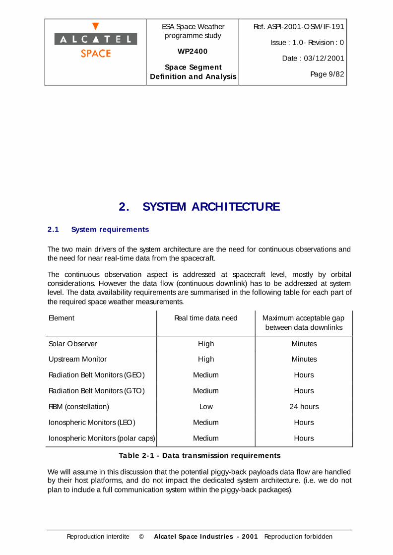
The continuous observation aspect is addressed at spacecraft level, mostly by orbitalconsiderations. However the data flow (continuous downlink) has to be addressed at systemlevel. The data availability requirements are summarised in the following table for each part ofthe required space weather measurements.
Element Real time data need Maximum acceptable gapbetween data downlinks
Solar Observer High Minutes
Upstream Monitor High Minutes
Radiation Belt Monitors (GEO) Medium Hours
Radiation Belt Monitors (GTO) Medium Hours
RBM (constellation) Low 24 hours
Ionospheric Monitors (LEO) Medium Hours
Ionospheric Monitors (polar caps) Medium Hours
Table 2-1 - Data transmission requirements
We will assume in this discussion that the potential piggy-back payloads data flow are handledby their host platforms, and do not impact the dedicated system architecture. (i.e. we do notplan to include a full communication system within the piggy-back packages).

ESA Space Weatherprogramme study
WP2400
Space SegmentDefinition and Analysis
Ref. ASPI-2001-OSM/IF-191
Issue : 1.0- Revision : 0
Date : 03/12/2001
Page 10/82
Reproduction interdite © Alcatel Space Industries - 2001 Reproduction forbidden
The architecture is therefore only dictated by the dedicated spacecraft data flows.
There are basically two ways to achieve a continuous downlink of a given data flow:
• One is to ensure the visibility of the spacecraft by a ground station at all times
• another is to use a relay on a set of spacecraft that have a continuous downlinkcapability, provided that the data rate can be ensured with a reasonable impact both onthe observing spacecraft and the relay spacecraft.
Depending on the actual data flow requirements for each type of measurements (ionospheric,magnetospheric, etc), the different possible architectures will be examined in terms ofperformance, complexity and cost of the overall system.
2.2 System options
These system options are presented in detail in WP2200-2300 report. Here are summarised thedifferent baseline options, not including options that could be implemented as additions to astandard system (such as a constellation of 30-50 satellites).
Considering that the solar wind in-situ measurements have to be performed outside the bowshock, two configurations are possible:
- 1 spacecraft located at L1 will constantly stay in the region of interest, at 1.5 million kmfrom the Earth in the sun direction. A continuous observation is therefore obtained with asingle spacecraft due to its particular orbit.
- Another solution is to have one or several spacecraft orbiting the Earth at a very highaltitude, in order to have them pass through the region of interest. If the orbits are elliptic(with measurements in the solar wind performed at apogee), the apogee will not remain inthe sun direction throughout the year, so several spacecraft will be needed to maintaincoverage. If the orbits are circular, they will have a very large period (several days) meaningthat several satellites will be required to maintain an acceptable gap between observationpasses in the solar wind upstream of the Earth.
The option consisting of several Earth-orbiting spacecraft appears much more complicated interms of number of spacecraft to launch, deploy and operate, for an observation andmeasurement potential that is less than the L1 option. From now on, this option will not bestudied further, and the baseline for solar wind monitoring will be the L1 option.
Solar observation can be performed from any location, as it is remote observation. Threerepresentative options will be considered here (but any location in view of the sun wouldtheoretically be suitable)
- Solar observation from an orbit around L1, which provides a continuous view of the sun.Only one spacecraft with sun observation instruments is needed.

ESA Space Weatherprogramme study
WP2400
Space SegmentDefinition and Analysis
Ref. ASPI-2001-OSM/IF-191
Issue : 1.0- Revision : 0
Date : 03/12/2001
Page 11/82
Reproduction interdite © Alcatel Space Industries - 2001 Reproduction forbidden
- Sun observation from a geosynchronous orbit
- Sun observation from low Earth orbit
Those orbits are either very well suited for sun observation or for data transmission to ground.Other orbits most often are less convenient for both of these functions, while not beingparticularly better in terms of platform design, launch strategies and operations.
Option Solar Observer UpstreamMonitor
Radiation BeltMonitors
Ionospheric Monitors
1 2 LEO L1
2 2 GEO L1
3 L1
1 GEO, 3 GTO +piggy-back
6 LEO + 2 oneccentric orbits
Table 2-2 - System options
2.3 Direct downlink to ground
The continuous data downlink requirement cannot be met using only spacecraft to ground links.However, a certain level of performance can be obtained. For each element of the system, whatcould be achieved with ground stations only is summarised hereafter:
2.3.1 LEO Solar Observer
The continuous downlink requirement will not be met with ground stations only, considering thesize of the instantaneous area in view of the satellite.
The central angle of the spherical cap in view of the satellite (with at least 10° elevation abovethe horizon) is 54° for a 1500km altitude (maximum order of magnitude of the LEO satellitealtitude). The number of ground stations required for continuous visibility of the satellite duringone revolution is therefore 7. Considering the rotation of the Earth the total number for full timecoverage is clearly unacceptable in terms of cost.
Moreover, a reduced number of ground stations would not allow a near-continuous downlink(with a delay of at most a few minutes, as required by the observations).
In this case where the requirement for continuous downlink is critical (sun data), one has toconsider a satellite data relay to meet this requirement, as the direct-to-ground data flow optionis excluded.

ESA Space Weatherprogramme study
WP2400
Space SegmentDefinition and Analysis
Ref. ASPI-2001-OSM/IF-191
Issue : 1.0- Revision : 0
Date : 03/12/2001
Page 12/82
Reproduction interdite © Alcatel Space Industries - 2001 Reproduction forbidden
2.3.2 GEO Solar Observer and Radiation Belt Monitor
The requirement has no particular impact on the overall system, as the satellite will always be inview of its control ground station, whether it is geostationary or geosynchronous only. Therequirement will have to be taken into account at satellite design level.
2.3.3 L1 Solar Observer and Upstream Monitor
The requirement can be met using three ground stations equally spaced around the equator,120° apart. Three such ground stations would allow continuous visibility of the spacecraft withsufficient elevation for data downlink.
It makes no difference in terms of spacecraft visibility whether the two functions (sun observationand solar wind monitoring) are grouped into one spacecraft or not.
2.3.4 GTO Radiation Belt Monitors
The orbit is such that the satellites spend most of the orbit at a high altitude, whereas the near-perigee phase is relatively short. Obtaining a good time coverage using equatorial groundstations is possible using at least three ground stations. However the perigee phase is at verylow altitude (a few hundred kilometers) making it difficult to have a good visibility of thesatellites during this phase without several more ground stations.
The satellite visibility performance achieved using three equatorial ground stations separated by120° is presented hereafter (using simplified geometric calculations, that are sufficient at thisstage).
These three ground stations (latitude = 0°, longitude = 0°, 120°E, 120°W) have visibility of anyspacecraft above 12000km in equatorial orbit around the Earth.
The three GTO spacecraft orbital characteristics are : perigee 650km, apogee 35786km,inclination 0°, and line of apsides separated by 120°.
Under these conditions the spacecraft are in view of one of the ground stations with more than10° elevation at least 83% of the time. Coverage under 12000km altitude (during the remaining17%) depends on the geometry of the Earth-satellite system. However the longest period withoutvisibility is on the order of 20 minutes.
As a summary
• Satellites visible more 90% of the orbit on average
• Longest time without visibility : about 20 minutes
Considering the data availability requirements presented in table 2-1, such a configuration isacceptable in terms of system performance.

ESA Space Weatherprogramme study
WP2400
Space SegmentDefinition and Analysis
Ref. ASPI-2001-OSM/IF-191
Issue : 1.0- Revision : 0
Date : 03/12/2001
Page 13/82
Reproduction interdite © Alcatel Space Industries - 2001 Reproduction forbidden
A configuration using only two ground stations (180° apart on the equator) is however notacceptable as it introduces gaps in the high altitude coverage of the satellites. In someconfigurations the satellite is not in view of any of the two ground stations at apogee, whichleads to several hours of coverage gap.
2.3.5 Radiation Belt Monitor Constellation
This part of the space segment is considered as optional in WP2200-2300 report. It might havea substantial impact on the data relay satellite design if the relay option is selected. Two optionsare possible :
- Consider this constellation as a stand-alone addition to the standard Space Weather system,or
- Implement on the data relay (if any) the ability to transmit the data generated by this part ofthe space segment, whether it is implemented at the same time as the rest of the system, orat a later stage to enhance its abilities.
In the eventuality of a stand alone constellation, given the very high altitude and period of thesatellites, it is possible to obtain long visibility periods with each of the satellites at their apogeesusing the existing ESA ground station network. Visibility around the perigee will be more difficultto achieve, but this is not a problem as the requirement on data transmission is not verydemanding (data transmission every 24h at worst).
2.3.6 LEO Ionospheric Monitors
Satellites orbits required for full capability observation :
- Two sun-synchronous spacecraft, 600 km altitude, 3h/15h and 9h/21h local time
- Two 625 km altitude, ~70° inclination satellites on the same orbit
- Two 600 km altitude (near-)equatorial satellites
The same remark as for the LEO Solar Observer applies. The spacecraft altitude is lower in thiscase, meaning that the ground area in view of one satellite is even smaller. At most, what canbe achieved at a realistic cost is a data downlink at each orbit, but not a continuous downlink.
2.3.7 Auroral ovals monitors
Satellite orbit required for observation :
- High inclination (~90°), eccentric orbit with apogee above the pole. (perigee 500 km,apogee 3 Re)
It seems reasonable to assume that a data link to the ground is required only when images aretaken by the spacecraft, i.e. when it is in view of the polar caps to be imaged. It is therefore

ESA Space Weatherprogramme study
WP2400
Space SegmentDefinition and Analysis
Ref. ASPI-2001-OSM/IF-191
Issue : 1.0- Revision : 0
Date : 03/12/2001
Page 14/82
Reproduction interdite © Alcatel Space Industries - 2001 Reproduction forbidden
possible to meet this requirement with a single high latitude ground station (if only north polarcap images are taken) or two if southern observations are also required. The fact that an highinclination elliptical orbit is baselined is in favor of this approach, as the spacecraft will be atapogee above the north pole. The high altitude of the satellite apogee introduces someflexibility in the selection of the high latitude ground station used for communication with thespacecraft.
2.4 Data relay strategies
Several possibilities exist for a satellite data relay permitting a continuous or near-continuousdownlink of the data for the different elements of the space segment. Three options areconsidered in the following discussion:
1. Two geostationary satellites dedicated to the data relay
2. Two Solar Observers in geostationary (or geosynchronous) orbit, also acting as data relays
3. Three Radiation Belt Monitors in GTO orbits, used as data relay
2.4.1 GEO relay
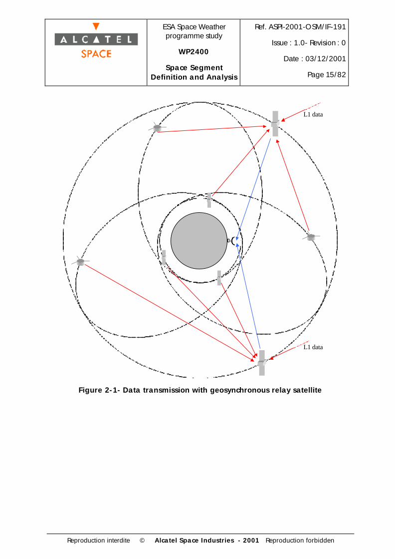
2.4.1.1 Dedicated relay satellites
This option consists of two geostationary or geosynchronous satellites dedicated to the relay ofdata from the elements of the space segment. The considered data sources are the potentialelements of the space weather system, namely:
- L1 Upstream Monitor
- L1 Upstream Monitor + Solar Observer, if combined
- LEO Solar Observer
- GTO Radiation Belt Monitors
- Radiation Belt Monitors Constellation
- LEO Ionospheric Monitors
- Polar caps Monitors
ESA Space Weatherprogramme study
WP2400
Space SegmentDefinition and Analysis
Ref. ASPI-2001-OSM/IF-191
Issue : 1.0- Revision : 0
Date : 03/12/2001
Page 15/82
Reproduction interdite © Alcatel Space Industries - 2001 Reproduction forbidden
L1 data
L1 data
Figure 2-1- Data transmission with geosynchronous relay satellite

ESA Space Weatherprogramme study
WP2400
Space SegmentDefinition and Analysis
Ref. ASPI-2001-OSM/IF-191
Issue : 1.0- Revision : 0
Date : 03/12/2001
Page 16/82
Reproduction interdite © Alcatel Space Industries - 2001 Reproduction forbidden
Solar ObserverL1 or LEO
Ground stations
Radiation BeltMonitorsGTO
IonosphericMonitorsLEO circular
Upstream MonitorL1
GEO data relay
Figure 2-2 - data flow architecture, dedicated relay, option 1
Solar ObserverGEO
Ground stations
Radiation BeltMonitorsGTO
IonosphericMonitorsLEO circular
Upstream MonitorL1
GEO data relay
Figure 2-3 - data flow architecture, dedicated relay, option 2
The advantage of this option is that it only requires at most two ground stations, and possiblyonly one, for the whole system for telemetry (TM), and they can be standard control segment forgeostationary satellites.
On the TC side there are two options : either it is also handled by the geosynchronous relays, ordirectly from the ground to the spacecraft. This depends on
• The level of autonomy of the different spacecraft
• The additional functions that must be implemented on the GEO relays to support a full TCcapability for the whole system (multidirectional transmit capability)

ESA Space Weatherprogramme study
WP2400
Space SegmentDefinition and Analysis
Ref. ASPI-2001-OSM/IF-191
Issue : 1.0- Revision : 0
Date : 03/12/2001
Page 17/82
Reproduction interdite © Alcatel Space Industries - 2001 Reproduction forbidden
• The opportunities of using existing ground stations for TC periods. Using dedicated groundstations is not desirable because it represents a loss of the advantage gained by using relaysatellites.
2.4.1.2 GEO combined Solar Observer and relay
This option combines the Sun observation payload and the data relay function on a singlesatellite. The satellite orbit might be dictated by payload pointing requirements (sun pointing) ordata relay requirements. Several options are being considered at this time
- Any orbit inclination is theoretically possible as long as the two satellites are not ineclipse simultaneously, and that a good coverage is achieved for the relay function.It is better to have the two satellites on the same orbit for this reason. A possibility isa 7° inclination, meaning that no inclination correction will be required if thespacecraft are launched on Ariane 5.
- a strictly geostationary orbit can be considered. The fact that the satellite is sun-pointed will introduce seasonal changes into the satellite attitude with respect to theEarth. On the other hand it will remain fixed with respect to the Earth surface
- a 23.4° inclined geosynchronous orbit is also an option, so that the orbit is in theecliptic plane. The will not be seasonal changes in the attitude of the satellite, but itwill not be fixed with respect to the Earth (north/south variations on a one orbit timescale)
The inclination selection however does not impact greatly the system architecture and will beexamined at platform level in the corresponding section of this document.
The overall system availability might be reduced in case of a GEO Solar Observer failure. In thecase of an L1 to GEO relay, at worst 70 minutes of visibility per day are lost, the remainingsatellite being in view of the sun almost 23 hours a day (In fact the loss of coverage is exactlythe same as for the Solar Observer instruments). However for the potential LEO to GEO relay,half the coverage disappears if a GEO satellite is lost, as a full Earth hemisphere is not in viewof the remaining GEO satellite.

ESA Space Weatherprogramme study
WP2400
Space SegmentDefinition and Analysis
Ref. ASPI-2001-OSM/IF-191
Issue : 1.0- Revision : 0
Date : 03/12/2001
Page 18/82
Reproduction interdite © Alcatel Space Industries - 2001 Reproduction forbidden
Solar ObserverGeosynchronous Ground stations
Radiation BeltMonitorsGTO
IonosphericMonitorsLEO circular
Upstream MonitorL1
Figure 2-4 - data flow architecture, integrated SO + relay
2.4.1.3 orbit requirements
If the two relay satellites are located 180° apart on their geosynchronous orbit, two groundstations are needed. These satellites maintain a continuous coverage of the LEO satellites at thealtitudes considered (600 km).
Geostationary satellites located less than 143° apart can be controlled by a single equatorialground station with 10° elevation. This would reduce the ground infrastructure and operationscosts, while still satisfying the observation requirement. However the coverage of the 600 kmLEO sphere is not complete : there is a small area up to 16° wide at the equator that is notcovered.
** include assumption on margin wrt earth surface for optical path **
GEOGEO
600km
143°
16°
Figure 2-5 - GEO relay coverage

ESA Space Weatherprogramme study
WP2400
Space SegmentDefinition and Analysis
Ref. ASPI-2001-OSM/IF-191
Issue : 1.0- Revision : 0
Date : 03/12/2001
Page 19/82
Reproduction interdite © Alcatel Space Industries - 2001 Reproduction forbidden
This geometrical characteristic leads to a 5 min coverage gap for an equatorial satellite at 600km altitude, and less than half an orbit for a polar satellite which orbit happens to be in thearea not covered, i.e. about 45 minutes at most, which is compatible with the data availabilityrequirements mentioned at the beginning of this chapter.
This option of a single ground station will therefore be selected in case the two GEO relays arechosen as the baseline scenario for data transmission.
2.4.2 GTO relay
A possibility exists of implementing a data relay from the LEO part of the space segment to theground via the GTO spacecraft. The performance of such a link will be less than that of ageostationary or geosynchronous relay, because both the LEO to GTO link and the GTO toground link are not continuous. The achievable coverage is described here.
The satellite to ground station link for the GTO S/C has already been described in the previoussection.
Considering the LEO to GTO link, and with no a priori knowledge of the relative positions of thedifferent satellites, one has to consider the visibility of the 600km altitude Earth-centred sphereby the three GTO satellites.
Orbit assumptions:
• Three 0° inclined GTO orbits with perigees 120° apart, with phased perigee (simultaneousperigee crossing)
• 100 km margin above the Earth surface for the optical path, meaning that the link betweentwo satellites shall not be closer than 100 km to the Earth
With these assumptions, the performance of the LEO to GTO link is as follows:
• full visibility is obtained 84.5% of the time. (meaning that all six LEO ionospheric monitorsare visible from the GTO spacecraft)
• This value reaches 95% for the equatorial pair of ionospheric monitors.
• the minimum latitude not in view of one satellite is plotted in the following graph (all thesatellites with a lower latitude than the one plotted are in view; some with a higher latitudemight still be in view, depending on the geometry of the system)

ESA Space Weatherprogramme study
WP2400
Space SegmentDefinition and Analysis
Ref. ASPI-2001-OSM/IF-191
Issue : 1.0- Revision : 0
Date : 03/12/2001
Page 20/82
Reproduction interdite © Alcatel Space Industries - 2001 Reproduction forbidden
Minimum visible latitude from GTO (3 satellites)
0
20
40
60
80
100
0 5 10 15 20 25 30 35 40 45 50 55 60 65 70 75 80 85 90 95 100
Figure 2-6 - GTO relay coverage (1)
• the percentage of the LEO sphere surface covered is plotted in the following graph
LEO sphere visibility proportion (3 satellites)
0
0,2
0,4
0,6
0,8
1
0 10 20 30 40 50 60 70 80 90
Figure 2-7 - GTO relay coverage (2)
The worst coverage is obviously obtained at the poles. The coverage could be increased usingtwo ground stations (one near each pole) providing visibility at the poles, if the coverage is notsufficient. This would provide a direct LEO to ground downlink capability when the LEOspacecraft pass over the poles.
A different satellite phasing could improve these values, by reducing the overlapping areas ofthe fields of view.
The values given here are only for the LEO to GTO link. The performance for the full data flowmust take into account the GTO to ground link as well. For real-time downlink both links needto be operational simultaneously. Otherwise, the access time is the time necessary to have asequence of a LEO to GTO data transfer, followed by a GTO to ground data transfer.

ESA Space Weatherprogramme study
WP2400
Space SegmentDefinition and Analysis
Ref. ASPI-2001-OSM/IF-191
Issue : 1.0- Revision : 0
Date : 03/12/2001
Page 21/82
Reproduction interdite © Alcatel Space Industries - 2001 Reproduction forbidden
As the visibility parameters greatly depend on the number of satellites (both GTO and LEO) andthe phasing between orbits (resonance, etc), a complete mission analysis study is necessary toderive more precise statistics on the downlink periods that can be achieved.
These geometric considerations show that the option of a data relay on the GTO radiation beltmonitors meets the requirements in terms of spacecraft and ground station visibility periods.
However there are several other aspects to take into account:
- The planned scientific payload is relatively simple, and the resources requirements are small(mass, power). This payload could easily be accommodated on spacecraft that would bespin-stabilised, which would even be better than 3-axis stabilisation for some experiments.
The communication equipment for data relay, on the other hand, would lead to a muchmore complex satellite. The different antennas will have to be accommodated on theplatform, the pointing being an issue that could even lead to require 3-axis stabilisationinstead of spin-stabilisation.
- The orbit is highly elliptic, which makes it more complex to implement a data relay than ona geostationary spacecraft. This also has an impact on the antenna pointing, because thegeometry of the system is much more variable.
- It is likely that from the resources point of view the driver for the platform sizing (and cost)will be the communications equipment and not the scientific payload.
- The use of standard communication equipment will be made difficult by the particular orbit(GTO), as very high radiation levels will be encountered throughout the spacecraft lifetime.
For all these reasons it appears that implementing the data relay on the GTO spacecraft willprove to be more difficult than on GEO spacecraft. This option, however, can be kept as abackup solution.
2.5 System options summary

ESA Space Weatherprogramme study
WP2400
Space SegmentDefinition and Analysis
Ref. ASPI-2001-OSM/IF-191
Issue : 1.0- Revision : 0
Date : 03/12/2001
Page 22/82
Reproduction interdite © Alcatel Space Industries - 2001 Reproduction forbidden
Element Direct to ground GEO relay GTO relay
LEO Solar Observer Performance insufficient Ok Performance insufficient
GEO Solar Observer Ok (1GS for 2 S/C) Onboard / N/A N/A
L1 Solar Observer At least 3 ground stationsnecessary
Ok Performance insufficient(GTO=>ground link)
Upstream Monitor At least 3 ground stationsnecessary
Ok Performance insufficient(GTO=>ground link)
RBM (GEO) Ok (1 GS) Onboard N/A
RBM (GTO) Ok (3 GS) Ok Onboard
RBM (constellation) Ok Ok Ok (but not required byvisibility conditions)
IM (LEO) Performance insufficient (withsmall number of GS)
Ok Depends of requiredperformance
IM (polar caps) 1 ground station per coveredpole, high latitude
Ok Ok
Number of groundstations
3 for GTO RBM and GEO or L1SO
IM not adequately covered.
1 high latitude for auroral imager
RBM constellation can be coveredby the aforementioned GS.
1 GS for GEO to ground 3 GS for GTO to ground
3 GS for L1 to ground (sameas previous but additionalantennae)
System robustness
(spacecraft failureeventuality – impact otherthan loss of onboardinstruments data)
Each spacecraft is independent ofthe rest of the space segment
Coverage loss is
- 39% for the LEO satellites
- low for GTO satellites(worst case = no GTOapogee - GEO relay link)
- at worst 70mn per day forL1 spacecraft
Coverage loss is about 1/3for the LEO spacecraft
Table 2-3 - System options peformances summary

ESA Space Weatherprogramme study
WP2400
Space SegmentDefinition and Analysis
Ref. ASPI-2001-OSM/IF-191
Issue : 1.0- Revision : 0
Date : 03/12/2001
Page 23/82
Reproduction interdite © Alcatel Space Industries - 2001 Reproduction forbidden
From this discussion it follows that a geostationary or geosynchronous data relay is desirable
The possible system implementations are
1 - L1 Solar Observer, GEO relay
2 - Combined GEO Solar Observer and relay
3 - Separate GEO Solar Observer and relay
4 - LEO Solar Observer and GEO relay
The following table presents the available options in terms of number of spacecraft. This is ofcourse a biased estimation of the development cost, as the cost the satellites depends on theiroperational orbit choice, payload mass, required performances... However this can give anorder of magnitude as there are many fixed costs to take into account in the development,production launch and operations of a spacecraft.
The number of spare spacecraft is simply taken to be the number of spacecraft types, to be ableto respond to one random failure among all the considered spacecraft.
The numbers presented in this table also take the Upstream Monitor into account, as there is aconfiguration where it can be combined with the Solar Observer.
A critical point that it is interesting to mention is the number of instrument sets that have to beproduced, given their high cost (estimated 80 MEuros from WP2200-2300 report, the recurrentcost being estimated to about 40 MEuros).

ESA Space Weatherprogramme study
WP2400
Space SegmentDefinition and Analysis
Ref. ASPI-2001-OSM/IF-191
Issue : 1.0- Revision : 0
Date : 03/12/2001
Page 24/82
Reproduction interdite © Alcatel Space Industries - 2001 Reproduction forbidden
Option 1 2 3 4
Number of Spacecraft(SO+UM+relay)
3/4
combined/separate SO and UM
3 5 5
Number of replacementspacecraft
2/3 2 3 3
Total spacecraft 5/7 5 8 8
Number of SolarObserver instrument sets(including spares)
2 3 3 3
Launches
(without spares)
2 2/3
dual / separate SO launches
3 3
Table 2-4 - Number of spacecraft vs. SO option
Another element to take into account is the fact that the GEO relay is the key point for datatransmission, and that system availability is critical. Therefore this element is a top priority interms of robustness considerations. It might be necessary to have an on-orbit spare satellite inorder to ensure the continuity of the service.
2.6 System scenarios selection
The different Space Weather programme scenarios have been selected by the entire Alcatelconsortium according to observation priorities, cost and programmatics aspects, as well as thespace segment performances described in the previous chapters.
As the purpose of this document is to describe the space segment of the Space Weatherprogramme, only the system scenarios that imply the deployment of dedicated spacecraft will behighlighted in this report. The individual spacecraft description will then be done in the nextchapters dedicated to the elements design.
2.6.1 Full Scale space segment
The full scale space segment option has been selected according to the performanceconsiderations mentioned above. Its main feature is the presence of two geosynchronous SolarObservers, also having radiation belt monitoring instruments as well as the communicationsfunctions necessary to relay to the ground the observation data from the rest of the spacesegment. This configuration requires a single ground station for the entire system.

ESA Space Weatherprogramme study
WP2400
Space SegmentDefinition and Analysis
Ref. ASPI-2001-OSM/IF-191
Issue : 1.0- Revision : 0
Date : 03/12/2001
Page 25/82
Reproduction interdite © Alcatel Space Industries - 2001 Reproduction forbidden
Spacecraft Number of spacecraft Orbit Instrumentation
Soft X-ray imagerEUV imager
MagnetographCoronagraph
H-alpha imagerSoft X-ray & UV flux monitor
EUV spectrographThermal plasma monitor
Mid energy particle monitorRadio spectrographSolar and galactic radiation monitor
Solar Wind monitorThermal plasma monitor
Mid energy particle monitorMagnetometer
Thermal plasma monitorMid energy particle monitor
MagnetometerWaves A
Waves BLow energy plasma monitor
E-field antennaNeutral mass spectrometer
GPS receiverTopside sounder
Low energy plasma monitorInterferometer
Neutral mass spectrometerGPS receiver
Topside sounderInterferometer
Neutral mass spectrometerGPS receiver
Topside sounderUV imager
Visible imager
apogee 35786km, perigee ~500km, both in the
equatorial planeinclination <18°
SSO, 3-15h and 9-21h, 600km altitude
Ionosphere/thermosphere monitoring
eccentric polar orbit (apogee ~3 Re)
1
2 equatorial, 600km
600km, 75° inclination2
2
Solar Observation 2
Magnetosphere monitoring 3
Geosynchronous, ~140° angular separation
L11Solar wind - heliosphere
Table 2-5 - Full scale space segment
2.6.2 Medium scale space segment
The medium scale space segment has been selected with an emphasis on the solar and solarwind observation. The data relay function present in the full scale system has been cancelled,meaning that the performance in terms of real time data will be less. The Solar Observer andUpstream Monitor have been grouped on a single spacecraft at L1, as the geosynchronous

ESA Space Weatherprogramme study
WP2400
Space SegmentDefinition and Analysis
Ref. ASPI-2001-OSM/IF-191
Issue : 1.0- Revision : 0
Date : 03/12/2001
Page 26/82
Reproduction interdite © Alcatel Space Industries - 2001 Reproduction forbidden
location was mainly driven by the data relay function. The other parts of the space segment(RBM and IM) have been reduced in scale and will require the use of separate ground stations.
Spacecraft Number of spacecraft Orbit Instrumentation
EUV imager
MagnetographCoronagraph
H-alpha imagerSoft X-ray & UV flux monitor
EUV spectrographRadio spectrograph
Solar and galactic radiation monitorSolar Wind monitor
Thermal plasma monitorMid energy particle monitor
MagnetometerThermal plasma monitorMid energy particle monitor
MagnetometerWaves A
Low energy plasma monitorE-field antenna
Neutral mass spectrometerGPS receiver
Topside sounder
2SSO, 3-15h and 9-21h,
600km altitude
Solar Observation / Solar wind - heliosphere
1 L1
Magnetosphere monitoring 3
apogee 35786km, perigee ~500km, both in the
equatorial planeinclination <18°
Ionosphere/thermosphere monitoring
Table 2-6 - Medium scale space segment
2.6.3 Minimum scale space segment
A minimum scale space segment has also been selected, aiming at maintaining a bareminimum observation capability. Its main features are
• the presence of a capable Upstream Monitor (similar to the full scale spacecraft), as this hasbeen considered a vital necessity
• a very reduced Solar Observer in LEO, allowing a reasonably good observation capabilityat low cost, but very far from satisfying the real-time data requirement
• a single Radiation Belt Monitor in GTO orbit, very good candidate for a cost effectivemicrosat launch on Ariane 5 ASAP.

ESA Space Weatherprogramme study
WP2400
Space SegmentDefinition and Analysis
Ref. ASPI-2001-OSM/IF-191
Issue : 1.0- Revision : 0
Date : 03/12/2001
Page 27/82
Reproduction interdite © Alcatel Space Industries - 2001 Reproduction forbidden
Spacecraft Number of spacecraft Orbit Instrumentation
EUV imagerCoronagraph
Soft X-ray & UV flux monitorEUV spectrograph
Radio spectrographSolar and galactic radiation monitor
Solar Wind monitorThermal plasma monitor
Mid energy particle monitorMagnetometerThermal plasma monitor
Mid energy particle monitorMagnetometer
Waves A
Solar Observation 1 SSO, 6-18h, 950km
Magnetosphere monitoring 1
apogee 35786km, perigee ~500km, both in the
equatorial planeinclination <18°
Solar wind - heliosphere 1 L1
Table 2-7 - Minimum scale space segment

ESA Space Weatherprogramme study
WP2400
Space SegmentDefinition and Analysis
Ref. ASPI-2001-OSM/IF-191
Issue : 1.0- Revision : 0
Date : 03/12/2001
Page 28/82
Reproduction interdite © Alcatel Space Industries - 2001 Reproduction forbidden
3. ELEMENT DESIGN - FULL SCALE SPACESEGMENT
3.1 Solar observer
The selected option for the Full Scale solar observation is to have two identical geostationarySolar Observers in orbit, so that at least one is in view of the sun at all times.
3.1.1 Payload requirements
The instruments accommodated on this satellite are the full scale solar observation instruments,and the inner-magnetospheric instruments meant to be operated in GEO orbit. The full set ofinstruments is summarised in Table 3-1.
WP2200-2300 ref. Instrument Mass (kg) Power (W) Telemetry (kbps)
1 Soft X-ray imager 25 20 702 EUV imager 28 20 283 Magnetograph 26 25 9,54 Coronagraph 25 25 505 Halpha imager 18 20 1206 Soft X-ray & UV flux monitor 5 5 0,28 EUV spectrograph 5 5 1
11 Thermal plasma monitor 6 8 212 Mid energy particle monitor 2 4 2
Total 140 132 282,7
Table 3-1 : Full scale SO payload summary
3.1.2 Orbital configuration and requirements
The selected orbit has been selected geosynchronous for communications reasons. The altitudeof the orbit is therefore 35786km.
The inclination can be selected according to several criteria :

ESA Space Weatherprogramme study
WP2400
Space SegmentDefinition and Analysis
Ref. ASPI-2001-OSM/IF-191
Issue : 1.0- Revision : 0
Date : 03/12/2001
Page 29/82
Reproduction interdite © Alcatel Space Industries - 2001 Reproduction forbidden
• Position of the satellite with respect to its control ground station ( fixed for i=0°; not fixed forany other inclination)
• Position of the sun with respect to the orbit plane (in the orbit plane for i=23.4° with properRAAN; outside of the orbit plane, and elevation varying in time for any other configuration)
• Inclination change after launch (none for i=7° if the spacecraft are launched by Ariane 5)
The inclination is selected to be 23.4° (both satellites in the ecliptic plane) as it is expected tofacilitate the relay antennae accommodation on the spacecraft.
In terms of orbital configuration of the two satellites, any Earth central angle of more than 17.7°is acceptable as it ensures that they are not in ecplise at the same time (including an arbitrary200km margin between the line of sight and the surface, to avoid atmospheric disturbances). Inother words the line of sight satellite-to-sun is never closer than 200km to the surface of theEarth for both SOs at the same time.
As far as the data relay function is concerned,
• The data received from the L1 Upstream Monitor imposes a further requirement on theseparation, as the lines of sight from the SO's to the UM are not parallel. The separationshould be larger than 18.2°, still with the aforementioned 200km margin.
• Considering the data links the SO's to the ground, the angular separation has to be limitedin order to allow the use of a single ground station for both spacecraft. The actual angledepends on the location of the ground station. For equatorial spacecraft and ground stationit has to be less than 143° (with 10° elevation of the S/C above the local horizon).

ESA Space Weatherprogramme study
WP2400
Space SegmentDefinition and Analysis
Ref. ASPI-2001-OSM/IF-191
Issue : 1.0- Revision : 0
Date : 03/12/2001
Page 30/82
Reproduction interdite © Alcatel Space Industries - 2001 Reproduction forbidden
3.1.3 Satellite configuration
1.5 m.
1.0 m.
2.0 m.
0.6 m.
1.4 m.
Solar array
Apogee Boost Motor
Central Tube
Instrumentaccommodation area
Platform equipment area
Propellant tanks
Pressurant tank
Figure 3-1 - GEO SO view (1)

ESA Space Weatherprogramme study
WP2400
Space SegmentDefinition and Analysis
Ref. ASPI-2001-OSM/IF-191
Issue : 1.0- Revision : 0
Date : 03/12/2001
Page 31/82
Reproduction interdite © Alcatel Space Industries - 2001 Reproduction forbidden
Magnetograph
EUV Spectrograph
EUV imagerSoft X-Ray imager
Coronagraph
H-alphaimagerSoft X-Ray & UV flux monitor
2.0 m.
Solar array
1.4 m.
1.0 m.
2.0 m.
Figure 3-2 - GEO SO view (2)

ESA Space Weatherprogramme study
WP2400
Space SegmentDefinition and Analysis
Ref. ASPI-2001-OSM/IF-191
Issue : 1.0- Revision : 0
Date : 03/12/2001
Page 32/82
Reproduction interdite © Alcatel Space Industries - 2001 Reproduction forbidden
3.1.4 System budgets
Spacecraft Mass Budget
Subsystem Mass Number Total massOBDH 20 1 20Power
PCDU 10 1 10Solar array 20 2 40
Batteries (Li-ion) 20 1 20
Structure 50 1 50Thermal 15 1 15AOCS
reaction wheels 5 4 20star trackers 3 2 6
IMU 2 2 4Sun sensors 1 2 2
CommL1 antenna 5 1 5
L1 electronics 5 1 5TMCU antenna 8 1 8
TMCU electronics 25 1 25TTC equipment 7 1 7
Propulsiontanks 25 2 50
press tank 15 1 1510N thrusters 0,65 16 10,4
tubing 5 1 5apogee boost motor 10 1 10
miscellaneous equipment 5 1 5
PayloadSoft X-ray imager 25 1 25
EUV imager 28 1 28Magnetograph 26 1 26
Coronagraph 25 1 25Halpha imager 18 1 18
Soft X-ray & UV flux monitor 5 1 5EUV spectrograph 5 1 5
Thermal plasma monitor 6 1 6Mid energy particle monitor 2 1 2
Total Spacecraft 472,4
Table 3-2 - GEO SO mass budget

ESA Space Weatherprogramme study
WP2400
Space SegmentDefinition and Analysis
Ref. ASPI-2001-OSM/IF-191
Issue : 1.0- Revision : 0
Date : 03/12/2001
Page 33/82
Reproduction interdite © Alcatel Space Industries - 2001 Reproduction forbidden
Spacecraft Power Budget
Subsystem Power (W)OBDH 25Power 20Thermal 15AOCS
reaction wheels 28star trackers 17
IMU 20Comm
L1 electronics 25TMCU electronics 150
TTC 20Payload
Soft X-ray imager 20EUV imager 20
Magnetograph 25Coronagraph 25
Halpha imager 20Soft X-ray & UV flux monitor 5
EUV spectrograph 5Thermal plasma monitor 8
Mid energy particle monitor 4Total spacecraft 452
Table 3-3 - GEO SO power budget
3.1.5 Communications subsystem
In the selected system configuration the following communications links have to be implementedon the Solar Observer:
• Instrument Data relay links from other spacecraft of the Space Weather system to the GEOSolar Observers
• Instrument data downlink from the GEO solar observers to the ground station(s)
• TM/TC link between the GEO solar observer and the ground

ESA Space Weatherprogramme study
WP2400
Space SegmentDefinition and Analysis
Ref. ASPI-2001-OSM/IF-191
Issue : 1.0- Revision : 0
Date : 03/12/2001
Page 34/82
Reproduction interdite © Alcatel Space Industries - 2001 Reproduction forbidden
IonosphericMonitors
UpstreamMonitor
SolarObserver
Radiation BeltMonitors
Figure 3-3 - Full scale segment - data flow
It must be noted that the TM/TC links for all other satellites will not relayed by the SolarObservers, (1) for system robustness reasons, (2) because the SO's would need a transmittingcapability towards the other spacecraft, which would add to the complexity of the satellite.
The required communication equipment on the solar observer can be summarised as follows:
• L1 Upstream Monitor to GEO Solar Observer data link
Electronics : 5 kg , 25 W
1 m diameter antenna, 2 axis steerable and pointed towards the L1 spacecraft : 5 kg
• GEO Solar Observer to ground station link
Onboard electronics : 25 kg, 150 W
2 m diameter antenna, 2 axis steerable : 8 kg
• TM/TC subsystem
Total 7 kg, 25 W
3.1.6 Power
A preliminary power subsystem sizing has been performed both for the batteries and the solararrays.
3.1.6.1 Batteries
The battery sizing has to take into account the total number of cycles over the spacecraftlifetime. The selected lifetime is 11 years. However there is some flexibility in the choice of the
ESA Space Weatherprogramme study
WP2400
Space SegmentDefinition and Analysis
Ref. ASPI-2001-OSM/IF-191
Issue : 1.0- Revision : 0
Date : 03/12/2001
Page 35/82
Reproduction interdite © Alcatel Space Industries - 2001 Reproduction forbidden
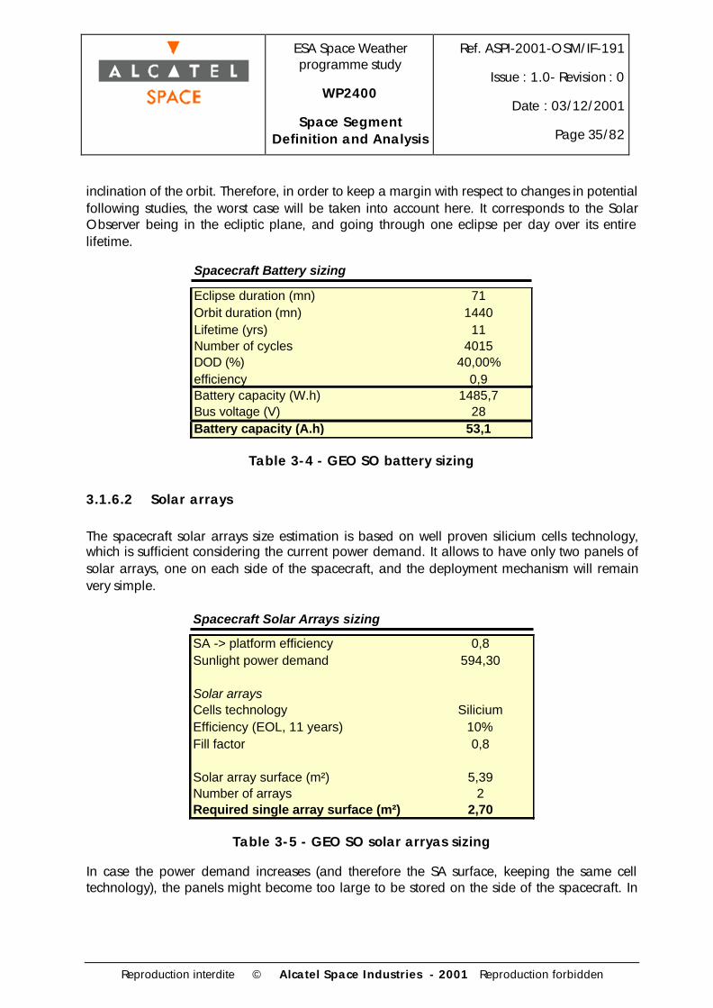
inclination of the orbit. Therefore, in order to keep a margin with respect to changes in potentialfollowing studies, the worst case will be taken into account here. It corresponds to the SolarObserver being in the ecliptic plane, and going through one eclipse per day over its entirelifetime.
Spacecraft Battery sizing
Eclipse duration (mn) 71Orbit duration (mn) 1440Lifetime (yrs) 11Number of cycles 4015DOD (%) 40,00%efficiency 0,9Battery capacity (W.h) 1485,7Bus voltage (V) 28Battery capacity (A.h) 53,1
Table 3-4 - GEO SO battery sizing
3.1.6.2 Solar arrays
The spacecraft solar arrays size estimation is based on well proven silicium cells technology,which is sufficient considering the current power demand. It allows to have only two panels ofsolar arrays, one on each side of the spacecraft, and the deployment mechanism will remainvery simple.
Spacecraft Solar Arrays sizing
SA -> platform efficiency 0,8Sunlight power demand 594,30
Solar arraysCells technology SiliciumEfficiency (EOL, 11 years) 10%Fill factor 0,8
Solar array surface (m²) 5,39Number of arrays 2Required single array surface (m²) 2,70
Table 3-5 - GEO SO solar arryas sizing
In case the power demand increases (and therefore the SA surface, keeping the same celltechnology), the panels might become too large to be stored on the side of the spacecraft. In

ESA Space Weatherprogramme study
WP2400
Space SegmentDefinition and Analysis
Ref. ASPI-2001-OSM/IF-191
Issue : 1.0- Revision : 0
Date : 03/12/2001
Page 36/82
Reproduction interdite © Alcatel Space Industries - 2001 Reproduction forbidden
this case there will be a need to either have four panels instead of two (increased deploymentcomplexity) or change the cells to AsGa solar cells which have a higher efficiency.
3.1.7 Propulsion
Considering the manoeuvres to be performed to reach the operational orbit of the SolarObserver from the GTO orbit in which it will be delivered by the launcher, a high efficiencybipropellant MON/MMH propulsion system is baselined.
In consists of
• An Apogee Boost Motor (ABM) in the 100-400N thrust range. 400N is the baselinefor most GEO telecom platforms, however the dry mass of the Solar Observer ismuch smaller, thus requiring less thrust for manoeuvres.
• 16 (TBC) attitude control thrusters, used for reaction wheels unloading andstationkeeping manoeuvres. The fuel and oxidizer are the same as for the mainengine.
• Two propellant tanks (identical volume) for storage of the propellant needed over the11 years lifetime.
• The associated equipment (valves, tubing, pressure transducers etc)
The following propellant budget has been performed in the option of a launch by Ariane 5 intoa 7° degrees inclination GTO orbit. The delta-V allocation includes the manoeuvres required toreach the operational orbit, and provisions for attitude control and stationkeeping over thespacecraft lifetime.
Spacecraft Propellant Budget
delta V 1700Isp 300Dry mass 472,4Propellant mass 369,34
Fuel MON/MMHdensity 1,16propellant volume 318,39number of tanks 2,00propellant volume per tank 159,20
Table 3-6 -GEO SO propellant budget
3.1.8 Launch strategy
The launch mass budget for one GEO Solar Observer is presented hereafter.

ESA Space Weatherprogramme study
WP2400
Space SegmentDefinition and Analysis
Ref. ASPI-2001-OSM/IF-191
Issue : 1.0- Revision : 0
Date : 03/12/2001
Page 37/82
Reproduction interdite © Alcatel Space Industries - 2001 Reproduction forbidden
Launch Mass Budget
S/C dry mass 472,4
propellant 369,3
launch wet mass 841,7
Table 3-7 - GEO SO launch mass budget
It appears that the launch mass is well under the Ariane 5 capability (only Ariane launcheravailable at the mission horizon - Ariane 4 will not be available anymore). It will therefore notbe cost efficient to launch both Solar Observers on the same dual launch.
A more reasonable strategy is to share two dual launches with other Ariane 5 customers,typically telecom platforms with a launch mass about 1 ton less than the Ariane 5 capability(which depends on the type of upper stage used).
3.2 Upstream Monitor
3.2.1 Payload requirements
The instruments considered for the L1 Upstream Monitor are the solar wind instruments with theaddition of the radiospectrograph.
WP2200-2300 ref. Instrument Mass (kg) Power (W) Telemetry (kbps)
7 Radio spectrograph 12 6 0,5
9 Solar and galactic radiation monitor 6 8 0,110 Solar Wind monitor 6 5 2
11 Thermal plasma monitor 6 8 212 Mid energy particle monitor 2 4 213 Magnetometer 1 2 0,2
Total 33 33 6,8
Table 3-8 - L1 UM payload summary
3.2.2 Orbital configuration and requirements
The Upstream Monitor will be placed on an orbit around the L1 Lagrange point, allowing acontinuous view of the sun. Such orbits (Halo or Lissajous orbits) are unstable, and will requireperiodic stationkeeping from the spacecraft, as is being done on SoHO and ACE.
Extensive mission analysis will be required in order to select the orbital transfer and insertionstrategy, select the orbit type and size, and assess the magnitude of the stationkeepingmanoeuvres over the spacecraft lifetime.

ESA Space Weatherprogramme study
WP2400
Space SegmentDefinition and Analysis
Ref. ASPI-2001-OSM/IF-191
Issue : 1.0- Revision : 0
Date : 03/12/2001
Page 38/82
Reproduction interdite © Alcatel Space Industries - 2001 Reproduction forbidden
For the purpose of this spacecraft dimensioning, the following assumptions have been made :
• The spacecraft will be launched into a GTO orbit on an ASAP5 mini launch (launch mass <300kg).
• The delta V needed to reach a transfer orbit to L1 has been estimated in terms of orbitenergy only. The required trajectory analysis will have to be performed in a following study.
• The insertion strategy is taken to be similar to the one used on Herschel - Planck uponarrival at L2. Therefore the same magnitude of insertion delta-V is assumed.
• The operational orbit size will also have to be studied, and the sun visibility, communicationrequirement, orbit stability and magnitude of the stationkeeping manoeuvres (fuel mass) willhave to be traded-off against each other. The assumption here is the ACE orbit, as the twospacecraft have very similar missions.
3.2.3 Spacecraft configuration
A spinned spacecraft concept has been selected, both for adequation with the payloadrequirements and for simplicity of the design and on-orbit control. The spin axis is orientedalong the sun-Earth line, and pointing at the Earth for communication reasons. The spacecrafthas an octogonal shape, with deployable solar panels mounted on four of its sides (conceptsimilar to ACE).
0.9 m.
1.3 m.
Solar and galacticradiation monitor
Solar wind monitor
Magnetometer
Mid-energy particlemonitor
Thermal plasmamonitor
Magnetometer
Magnetometerelectronics
Solar arrays
Propellant tank 0.6 m.
1.0 m.
Figure 3-4 - L1 UM, sunside view

ESA Space Weatherprogramme study
WP2400
Space SegmentDefinition and Analysis
Ref. ASPI-2001-OSM/IF-191
Issue : 1.0- Revision : 0
Date : 03/12/2001
Page 39/82
Reproduction interdite © Alcatel Space Industries - 2001 Reproduction forbidden
1.3 m.
0.9 m. Launcher interfaceASAP5 miniThruster
Solar array
0.8 m.
0.9 m.
Figure 3-5 - L1 UM, side view
3.2.4 System budgets
Spacecraft Mass Budget
Subsystem Mass Number Total massOBDH 10 1 10Power
PCDU 10 1 10solar panels 4 4 16
Structure 25 1 25Thermal 10 1 10AOCS 12 1 12Comm
TMCU electronics 15 1 15Antenna 5 1 5
TTC 7 1 7
Propulsion20N thrusters 0,5 4 2
1N thrusters 0,25 8 2hydrazine tank 7 1 7
misc equipment 2 1 2tubing 2 1 2
PayloadRadio spectrograph 12 1 12
Solar and galactic radiation monitor 6 1 6Solar Wind monitor 6 1 6
Thermal plasma monitor 6 1 6Mid energy particle monitor 2 1 2
Magnetometer 1 1 1Total Spacecraft 158
Table 3-9 - L1 UM mass budget

ESA Space Weatherprogramme study
WP2400
Space SegmentDefinition and Analysis
Ref. ASPI-2001-OSM/IF-191
Issue : 1.0- Revision : 0
Date : 03/12/2001
Page 40/82
Reproduction interdite © Alcatel Space Industries - 2001 Reproduction forbidden
Spacecraft Power Budget
Subsystem Power (W)OBDH 15Power 10Thermal 15AOCS 20Comm
TMCU 90TTC 30
PayloadRadiospectrograph 6
Solar and galactic radiation monitor 8Solar Wind monitor 5
Thermal plasma monitor 8Mid energy particle monitor 4
Magnetometer 2Total spacecraft 213
Table 3-10 - L1 UM power budget
3.2.5 Communication subsystem
A preliminary sizing of the Upstream Monitor communication subsystem for the L1 to GEOtransmissions and TTC equipment is as follows:
• 1m reflector antenna, 2 axis steerable, 5kg
• Onboard electronics, 15kg, 90W
• TTC subsystem : 7kg, 30W
3.2.6 Power subsystem
The spacecraft will not go through eclipses during its operational lifetime at L1. The nominalpower susbsystem operations make use of Solar Arrays, and a Power Conditionning andDistribution Unit (PCDU) only. However batteries will be required for (a) the launch andinsertion phase, during which eclipses can occur while the satellite is still in Earth orbit, and (b)contingency, i.e. in case the sun pointing attitude is temporarily lost during the operationallifetime.
For the purpose of this pre-sizing of the spacecraft, only the nominal case will be covered. Thecontingency cases should be covered in later studies, as they depend on a lot of factors such asS/C configuration, FDIR performances, AOCS performances etc.
A first cut of the solar arrays surface has been performed, and is summarised in the followingtable.

ESA Space Weatherprogramme study
WP2400
Space SegmentDefinition and Analysis
Ref. ASPI-2001-OSM/IF-191
Issue : 1.0- Revision : 0
Date : 03/12/2001
Page 41/82
Reproduction interdite © Alcatel Space Industries - 2001 Reproduction forbidden
Spacecraft Solar Arrays sizing
Spacecraft power 213SA -> platform efficiency 0,8SA power 266,25
Solar arraysCells technology AsGaEfficiency (EOL, 11 years) 13%Fill factor 0,8Max sun angle (°) 20
Solar array surface (m²) 1,98Number of arrays 4Required single array surface (m²) 0,49
Table 3-11 - L1 UM solar arrays sizing
3.2.7 Propulsion subsystem
As was previoulsy pointed out in the introduction to the Upstream Monitor, the actual trajectoryanalysis for deployment at L1, and associated delta-V calculations, need to be performed toconfirm this pre-sizing.
The assumed total delta-V required for the 11 years of the mission was taken to be 900m/s,including deployment from the initial orbit to the L1 orbit, and stationkeeping for the entirelifetime.
Considering this delta-V requirement and the expected launch mass of the spacecraft, it isproposed to use a monopropellant propulsion subsystem, using hydrazine. The low dry mass ofthe spacecraft should allow the use of four 20N thrusters used for orbit manoeuvres as well asattitude control, and of 8 (TBC) 1N thrusters for attitude control only.
The propellant budget for the mission is summarised in the following table.
Spacecraft Propellant Budget
delta V 900Isp 210Dry mass 158Propellant mass 86,56
Fuel N2H4density 1,00propellant volume 86,56tank diameter 0,55
Table 3-12 - L1 UM propellant budget

ESA Space Weatherprogramme study
WP2400
Space SegmentDefinition and Analysis
Ref. ASPI-2001-OSM/IF-191
Issue : 1.0- Revision : 0
Date : 03/12/2001
Page 42/82
Reproduction interdite © Alcatel Space Industries - 2001 Reproduction forbidden
3.2.8 Launch
The selection of the launch strategy is based on cost minimisation. The objective is to use the300kg capability of the ASAP5 mini launch to GTO, and make the transfer from GTO to L1 withonboard propulsion. The launch mass budget for this option is as follows.
Launch Mass Budget
S/C dry mass 158,0propellant 86,6launch wet mass 244,6
max launch mass 300,0margin 22,7%
Table 3-13 - L1 UM launch mass budget
Provided the magnitude of the required manoeuvres for deployment and insertion into the finalorbit is confirmed by accurate mission analysis, this option could prove to be a cost-efficient wayof implementing a European Upstream Monitor.
3.3 Radiation Belt Monitors
3.3.1 Payload requirements
The payload considered for the Radiation Belt Monitors is presented in the table hereafter. Thebaseline mission lifetime is 5 years. Given the harsh radiation environment on this orbit, alonger mission duration is not considered optimal, and design issues linked to radiations wouldbe increased.
WP2200-2300 ref. Instrument Mass (kg) Power (W) Telemetry (kbps)
11 Thermal plasma monitor 5 8 2
12 Mid energy particle monitor 2 4 213 Magnetometer 1,2 2 0,2
14 Waves A 1,3 1,2 2Waves B 8 0,6 2
15 Neutral particle imager 3 3 2
Total 20,5 18,8 10,2
Table 3-14 - RBM payload requirements
3.3.2 Orbital configuration and launch strategies
The selected orbital configuration is three low inclination elliptical orbits, with a 120° separationbetween each line of apsides.

ESA Space Weatherprogramme study
WP2400
Space SegmentDefinition and Analysis
Ref. ASPI-2001-OSM/IF-191
Issue : 1.0- Revision : 0
Date : 03/12/2001
Page 43/82
Reproduction interdite © Alcatel Space Industries - 2001 Reproduction forbidden
Figure 3-6 - RBM orbits configuration
Apogee altitude 35786 km
Perigee altitude About 500 km
Inclination Less than18°
Argument of perigee 0° or 180°
Right ascension of ascending node Separated by 120°
Table 3-15 - RBM orbital elements
Two launch strategies have been considered up to now, that lead to two completely differentspacecraft concepts. They will both be presented in this report.
The first option consists of a dedicated launch in low Earth orbit, in which the three satellites aredelivered at once. The deployment strategy takes advantage of the natural precession of theorbits in order to obtain the required spacing (strategy similar to STORMS).
The second option consists of three separate Ariane 5 ASAP micro launches, the three RBMbeing delivered directly into their final orbit. The advantage of this solution is a low-cost type ofsatellite, with minimal propulsion capabilities. However the programmatics constraint areimportant, because of the requirement on the launch dates to obtain the required orbit spacing,and on the availability of ASAP5 slots on the desired launches. For this reason the dedicatedlaunch is the baseline for this part of the space segment.

ESA Space Weatherprogramme study
WP2400
Space SegmentDefinition and Analysis
Ref. ASPI-2001-OSM/IF-191
Issue : 1.0- Revision : 0
Date : 03/12/2001
Page 44/82
Reproduction interdite © Alcatel Space Industries - 2001 Reproduction forbidden
3.3.3 Dedicated launch option
3.3.3.1 Deployment sequence
The apsidal line of the three orbits have to be separated by 120°. This separation will beaccomplished using the orbit perturbations, instead of a costly manoeuvre.
The deployment sequence is as follows:
- the three satellites are launched into a 350 km 18° inclination circular orbit. The PSLVperformance to this orbit is 3400 kg.
- Satellite 1 is injected into a 350x35786 km, 18° inclination, argument of perigee 0° orbit.The total delta V for this sequence of manoeuvres is 2440 m/s.
- At apogee, the perigee is raised to 650 km. If required by the mission, this manoeuvre canbe combined with an inclination change to 0°.
On this orbit the right ascending node precession is -7.86°/day. Therefore the time required toachieve a 60° rotation of the orbit plane is 7.5 days.
- 7.5 days later satellite 2 is injected into a 350x35786 km, 18° inclination, argument ofperigee 180° orbit. The same sequence of manoeuvres follows to put satellite 2 on its finalorbit.
- 15 days later the same sequence is applied to satellite 3,with argument of perigee 0° atinjection.
Advantages of this solution:
- The constellation deployment only takes 15 days from launch, due to the precession rate ofthe ascending node on this orbit.
- In the case of inclined orbits, two satellites have an argument of perigee of 0°, while thevalue is 180° for the other one (for equatorial orbits this does not apply). The minimum timein LEO can be obtained this way. However a deployment with the same argument ofperigee can be obtained, taking 28 days instead of 14.
Drawbacks of this solution
- The required total delta V is high, implying the use of a high thrust engine, to reduce gravitylosses. The manoeuvres might have to be performed sequentially to minimise gravity losses.
- Large propellant tanks will have to be included on the three spacecraft.

ESA Space Weatherprogramme study
WP2400
Space SegmentDefinition and Analysis
Ref. ASPI-2001-OSM/IF-191
Issue : 1.0- Revision : 0
Date : 03/12/2001
Page 45/82
Reproduction interdite © Alcatel Space Industries - 2001 Reproduction forbidden
3.3.3.2 Spacecraft configuration
The spacecraft configuration is also similar to STORMS. A cylindrical conguration has beenchosen for the three satellites, allowing them to be stacked at launch and allowing a reasonablemechanical behaviour of the stacked structure.
3.3.3.3 System budgets
Spacecraft Mass Budget
Subsystem Mass Number Total massOBDH 15 1 15Power
solar arrays 8 1 8battery 10 1 10PCDU 5 1 5
Structure 100 1 100Thermal 10 1 10AOCS
star trackers 3 2 6IMU 2 2 4
sun sensors 0,2 2 0,4Comm
TMCU antennas 1 2 2TMCU electronics 10 1 10
TTC equipment 5 1 5
Propulsiontanks 10 4 40
press tank 10 1 1010N thrusters 0,7 8 5,6
tubing 5 1 5apogee boost motor 5 1 5
miscellaneous equipment 5 1 5
PayloadThermal plasma monitor 5 1 5
Mid energy particle monitor 2 1 2Magnetometer 1,2 1 1,2
Waves A 1,3 1 1,3Waves B 8 1 8
Neutral particle imager 3 1 3Total Spacecraft 266,5
Table 3-16 - RBM mass budget (dedicated launch)

ESA Space Weatherprogramme study
WP2400
Space SegmentDefinition and Analysis
Ref. ASPI-2001-OSM/IF-191
Issue : 1.0- Revision : 0
Date : 03/12/2001
Page 46/82
Reproduction interdite © Alcatel Space Industries - 2001 Reproduction forbidden
Spacecraft Power Budget
Subsystem Power (W)OBDH 15Power 10Thermal 10AOCS
star trackers 5IMU 10
CommTMCU electronics 30
TTC 10
Payload
Thermal plasma monitor 8Mid energy particle monitor 4
Magnetometer 2Waves A 1,2Waves B 0,6
Neutral particle imager 3Total spacecraft 108,8
Table 3-17 - RBM power budget (dedicated launch)
3.3.3.4 Power subsystem
Spacecraft Battery sizing
Eclipse duration (mn) 130
Orbit duration (mn) 640
DOD (%) 40,00%
efficiency 0,8
Battery capacity (W.h) 727,9Bus voltage (V) 28
Battery capacity (A.h) 26,0
Spacecraft Solar Arrays sizing
SA -> platform efficiency 0,9Sunlight power demand 149,9
Solar arraysCells technology AsGaEfficiency (EOL, 5 years) 16%Fill factor 0,8
Solar array surface (m²) 0,8Number of arrays 1Required single array surface (m²) 0,8
Table 3-18 - RBM power subsystem sizing

ESA Space Weatherprogramme study
WP2400
Space SegmentDefinition and Analysis
Ref. ASPI-2001-OSM/IF-191
Issue : 1.0- Revision : 0
Date : 03/12/2001
Page 47/82
Reproduction interdite © Alcatel Space Industries - 2001 Reproduction forbidden
A preliminary sizing of the spacecraft power subsystem has bee performed based on the worsteclipse time encountered in the orbit, and on the spacecraft power budget.
The calculated solar array surface is for an array perpendicular to the sun direction. For aspinning spacecraft with solar cells placed on the circumference, this represents the area of theprojection of the illuminated panel on a plane perpendicular to the sun direction.
3.3.3.5 Propulsion subsystem
In order to perform the large insertion delta-V required to reach the final orbit, a bipropellantMON/MMH system is baselined.
It consists of
• A large thrust main engine for the insertion manoeuvre
• 8 low thrust attitude control thrusters
• 4 propellant tanks (2 for fuel, 2 for oxydizer)
• A pressurant tank (helium storage)
• Miscellaneous equipments (tubing, valves…)
Spacecraft Propellant Budget
delta V 2650Isp 300Dry mass 266,5Propellant mass 389,27
Fuel MON/MMHdensity 1,16propellant volume 335,58number of tanks 4,00volume per tank 83,90
Table 3-19 - RBM propellant budget (dedicated launch)
3.3.3.6 Launch
The three RBMs would be launched as a stack on a PSLV launcher.
The launch mass budget for the three spacecraft is as follows

ESA Space Weatherprogramme study
WP2400
Space SegmentDefinition and Analysis
Ref. ASPI-2001-OSM/IF-191
Issue : 1.0- Revision : 0
Date : 03/12/2001
Page 48/82
Reproduction interdite © Alcatel Space Industries - 2001 Reproduction forbidden
Launch Mass Budget
S/C dry mass 266,5propellant 389,3launch wet mass (1 satellite) 655,8
launch wet mass (3 satellites) 1967,4
max launch mass 3400,0margin 72,8%
Table 3-20 - RBM dedicated launch mass budget
This mass budget shows sufficient mass margin to have a good confidence on the outcome of afeasibility study on the Radiation Belt Monitors. It also shows that the instrumentation can beadded on the spacecraft at little cost, as resources
3.3.4 ASAP5 launch option
3.3.4.1 Spacecraft configuration
According to the ASAP5 user's guide, the allocated volume for a microsatellite has a squarebase of 600x600 mm and a height of 710 mm.
Given the fact that the spacecraft power budget is, for preliminary sizing, identical to the one forthe dedicated launch RBMs, it is not possible to have body-mounted solar panels, as the crosssection of the allocated spacecraft volume is less than the required solar array surface.
An ACE-like configuration will therefore be proposed : spinning spacecraft with its spin axisdirected towards the sun. The satellite will have a square base of 500x500 mm, leaving 50 mmto accommodate a deployable solar panel on each side. The satellite height is estimated toabout 350 mm, but is in any case limited by the stability requirements associated with the spinstabilisation.
Given the very low resources available on this type of launch, both from the volume and masspoints of view, no propulsion subsystem has been selected in the baseline. The main point ofconcern with this strategy is the atmospheric drag at perigee. The standard perigee altitude ofan Ariane 5 GTO orbit is 560km. Atmospheric drag will cause a decrease of the apogeealtitude over the mission lifetime. A precise analysis will be required to assess the apogeealtitude loss over the considered lifetime (currently five years) and decide if it is compatible withthe RBM mission and observation requirements.

ESA Space Weatherprogramme study
WP2400
Space SegmentDefinition and Analysis
Ref. ASPI-2001-OSM/IF-191
Issue : 1.0- Revision : 0
Date : 03/12/2001
Page 49/82
Reproduction interdite © Alcatel Space Industries - 2001 Reproduction forbidden
3.3.4.2 System budgets
Spacecraft Mass Budget
Subsystem Mass Number Total massOBDH 8 1 8Power
solar arrays 2 4 8battery 8 1 8PCDU 5 1 5
Structure 12 1 12Thermal 5 1 5AOCS
star trackers 3 2 6IMU 2 2 4
sun sensors 0,2 2 0,4Comm
TMCU antennas 1 2 2TMCU electronics 10 1 10
TTC equipment 5 1 5Payload
Thermal plasma monitor 5 1 5Mid energy particle monitor 2 1 2
Magnetometer 1,2 1 1,2Waves A 1,3 1 1,3Waves B 8 1 8
Neutral particle imager 3 1 3Total Spacecraft 93,9
Table 3-21 - Microsat RBM mass budget
As previously mentioned, in this first cut the RBM power budget is taken to be the same for boththe dedicated and ASAP5 launch.

ESA Space Weatherprogramme study
WP2400
Space SegmentDefinition and Analysis
Ref. ASPI-2001-OSM/IF-191
Issue : 1.0- Revision : 0
Date : 03/12/2001
Page 50/82
Reproduction interdite © Alcatel Space Industries - 2001 Reproduction forbidden
Spacecraft Power Budget
Subsystem Power (W)OBDH 15Power 10Thermal 10AOCS
star trackers 5IMU 10
CommTMCU electronics 30
TTC 10
PayloadThermal plasma monitor 8
Mid energy particle monitor 4Magnetometer 2
Waves A 1,2Waves B 0,6
Neutral particle imager 3Total spacecraft 108,8
Table 3-22 - Microsat RBM power budget
3.3.4.3 Power subsystem
The battery capacity and required solar array surface of this RBM microsat concept are the sameas the dedicated launch concept, as the power requirements are identical. The difference is thenumber of solar panels, as there are 4 deployable panels of the microsat RBM. Given the verylimited surface available for solar panels, very high efficiency cells have been selected, with amoderate impact on the cost, as they are more expensive, but in small number.

ESA Space Weatherprogramme study
WP2400
Space SegmentDefinition and Analysis
Ref. ASPI-2001-OSM/IF-191
Issue : 1.0- Revision : 0
Date : 03/12/2001
Page 51/82
Reproduction interdite © Alcatel Space Industries - 2001 Reproduction forbidden
Spacecraft Battery sizing
Eclipse duration (mn) 130Orbit duration (mn) 640
DOD (%) 40,00%efficiency 0,8Battery capacity (W.h) 727,9Bus voltage (V) 28
Battery capacity (A.h) 26,0
Spacecraft Solar Arrays sizing
SA -> platform efficiency 0,9Sunlight power demand 149,9
Solar arraysCells technology AsGaEfficiency (EOL, 5 years) 21%Fill factor 0,8
Solar array surface (m²) 0,6Number of arrays 4Required single array surface (m²) 0,2
Table 3-23 - Microsat RBM power subsystem sizing
3.3.4.4 Launch
Launch Mass Budget
S/C dry mass 93,9
max launch mass 120,0margin 27,8%
Table 3-24 - Microsat RBM launch mass budget
3.4 Ionospheric monitors
The Ionospheric/Thermospheric part of the full-scale space segment is presented in Figure 3-7.

ESA Space Weatherprogramme study
WP2400
Space SegmentDefinition and Analysis
Ref. ASPI-2001-OSM/IF-191
Issue : 1.0- Revision : 0
Date : 03/12/2001
Page 52/82
Reproduction interdite © Alcatel Space Industries - 2001 Reproduction forbidden
Highly eccentric orbit : M;F- UV imager
High inclined LEO : F- Interferometer- Neutral mass spectrometer- GPS receiver- Topside sounder- Particle spectrometer
Equatorial LEO : F- Interferometer- Neutral mass spectrometer- GPS receiver- Topside sounder
Polar-sun synchroneous orbits : M;F- Particle- E-field antenna- Neutral mass spectrometer- GPS receiver- Topside sounder
Figure 3-7 - Ionospheric space segment (F=full scale; M=medium scale)
The individual spacecraft launch and deployment strategies, as well as preliminary design, areaddressed in the following sections.
3.4.1 LEO Sun-synchronous IM
3.4.1.1 Payload requirements
The SSO spacecraft payload requirements are presented in Table 3-25.

ESA Space Weatherprogramme study
WP2400
Space SegmentDefinition and Analysis
Ref. ASPI-2001-OSM/IF-191
Issue : 1.0- Revision : 0
Date : 03/12/2001
Page 53/82
Reproduction interdite © Alcatel Space Industries - 2001 Reproduction forbidden
WP2200-2300 ref. Instrument Mass (kg) Power (W) Telemetry (kbps)
16 E-field antenna 2,7 0,5 2
18 Low energy plasma monitor 2 4 1
20 Neutral mass spectrometer 2,7 7,4 1
24 GPS receiver 8,5 12 0,1
25 Topside sounder 10 10 1
Total 25,9 33,9 5,1
Table 3-25 - SSO IM payload requirements
3.4.1.2 Launch and deployment strategy
The two sun-synchronous Ionospheric Monitors have orbits that have local times at equatorcrossing of 3h/15h and 9h/21h. The two orbital planes are separated by 90°. There are twopossible strategies to deploy these satellites:
• Two separate launches (but which can be dual launches with other missions). In this case thesatellites will have a very limited propulsion subsystem, for stationkeeping only.
• A single launch, with manoeuvres to reach the final orbits with the required local hours. Inthis strategy, it is not possible to perform the orbital plane separation using propulsion only,as this leads to an unacceptable amount of propellant required. The other way is to use astrategy similar to the one used for the RBM.
Single launch deployment strategy
The satellites would be launched into an intermediate orbit, a sun-synchronous 600km 6h/18horbit. This orbit is in between the two desired orbits and has a 97.8° inclination. Then eachsatellite performs an inclination change of a few degrees (while keeping the altitude constant),in opposite directions, i.e. one of the satellites increases its inclination by a few degrees and theother one decreases it by the same amount. This introduces a drift of the orbit planes inopposite directions with respect to the initial orbit. When the desired angular separation isreached, the inclination is corrected back to the initial value of 97.8°.
S/C #1 S/C #2
Figure 3-8 : SSO IM Deployment strategy

ESA Space Weatherprogramme study
WP2400
Space SegmentDefinition and Analysis
Ref. ASPI-2001-OSM/IF-191
Issue : 1.0- Revision : 0
Date : 03/12/2001
Page 54/82
Reproduction interdite © Alcatel Space Industries - 2001 Reproduction forbidden
This deployment sequence starting with a 6h/18h orbit leads one of the satellites to have itsascending node on the sunlit side of the Earth, and the other on the nightside. If both ascendingnodes a required to be on the same side of the planet the starting orbit for deployment shall bea noon/midnight orbit, leading to longer eclipse durations than during the nominal lifetime. Theadvantage of the 6h/18h is that there are no eclipses at the beginning of the deploymentphase.
For large inclination changes the deployment sequence will be shorter, but the propellant massrequired will be higher. Table 3-26 summarises the duration of the sequence for severalinclination changes.
Monopropellant (Isp = 210s)
Bipropellant (Isp = 310s)
3 791,4 46,8 29,7 119
4 1055,1 66,9 41,5 90
5 1318,7 89,7 54,3 726 1582,2 115,6 68,2 59
7 1845,6 144,9 83,5 51
Inclination change (°)
Propellant mass(in % of s/c dry mass)
Total Delta VDeployment duration
(days)
Table 3-26 : SSO IM deployment sequence duration
Two propulsion subsystems types have been envisaged : monopropellant and bipropellant. Theobjective of this launch strategy being to save the cost of one launch, the objective is to build aspacecraft which cost does not exceed, by half the launch cost, the cost of the separate launchspacecraft (that has a bare minimum propulsion subsystem). It is not clear that the bipropellantsystem will satisfy this requirement.
For the purpose of this study a monopropellant system is taken as the baseline in order to limitthe S/C cost. Should this option be studied at a later stage, the trade-off on the propulsionsubsystem type shall be consolidated.
Taking as a baseline a dual Rockot launch (cost-effective, dual launch capability), the launchercapability in the required orbit is 970kg. Keeping a 20% system margin at launch, this meansthat for a dual launch each of the satellite masses shall not exceed 400kg including propellant.
Considering the monopropellant propulsion and the launch mass target, the strategy with a 4°inclination change will be selected. It should be noted that a provision of propellant forstationkeeping shall be added to the deployment delta-V requirement.

ESA Space Weatherprogramme study
WP2400
Space SegmentDefinition and Analysis
Ref. ASPI-2001-OSM/IF-191
Issue : 1.0- Revision : 0
Date : 03/12/2001
Page 55/82
Reproduction interdite © Alcatel Space Industries - 2001 Reproduction forbidden
3.4.1.3 System budgets
Spacecraft Mass Budget
Subsystem Mass Number Total massOBDH 10 1 10Power
solar arrays 8 2 16battery 10 1 10PCDU 5 1 5
Structure 70 1 70Thermal 10 1 10AOCS
star trackers 3 2 6IMU 2 2 4
sun sensors 0,5 2 1reaction wheels 5 4 20
CommTM equipment (ISL) 5 1 5
TTC equipment 5 1 5Propulsion
tanks 12 1 1210N thrusters 0,7 8 5,6main engine 4 1 4
tubing 4 1 4miscellaneous equipment 4 1 4
PayloadLow energy plasma monitor 2,7 1 2,7
Interferometer 2 1 2Neutral mass spectrometer 2,7 1 2,7
GPS receiver 8,5 1 8,5Topside sounder 10 1 10
Total Spacecraft 217,5
Table 3-27 - SSO IM (full scale) mass budget

ESA Space Weatherprogramme study
WP2400
Space SegmentDefinition and Analysis
Ref. ASPI-2001-OSM/IF-191
Issue : 1.0- Revision : 0
Date : 03/12/2001
Page 56/82
Reproduction interdite © Alcatel Space Industries - 2001 Reproduction forbidden
Spacecraft Power Budget
Subsystem Power (W)OBDH 15Power 15Thermal 20AOCS
star trackers 17IMU 20
reaction wheels 20Comm
TM electronics 20TTC 10
PayloadE-field antenna 0,5
Low energy plasma monitor 4Neutral mass spectrometer 7,4
GPS receiver 12Topside sounder 10
Total spacecraft 170,9
Table 3-28 - SSO IM (full scale) power budget
3.4.1.4 Propulsion subsystem
As stated in the deployment strategy section, a monopropellant hydrazine propulsion subsystemhas been selected. The porpellant budget is as follows, including the deployment delta-V and a200m/s allocation for station keeping:
Spacecraft Propellant Budget
delta V 1255Isp 210Dry mass 217,5Propellant mass 182,47
Fuel N2H4density 1,00propellant volume 182,47number of tanks 1,00volume per tank 182,47
Table 3-29 - SSO IM (full scale) propellant budget
3.4.1.5 Power subsystem
The power subsystem is sized according to the worst case eclipse time. The sun elevation withrespect to the orbit plane is about 45° (with seasonal changes). Given the instrument

ESA Space Weatherprogramme study
WP2400
Space SegmentDefinition and Analysis
Ref. ASPI-2001-OSM/IF-191
Issue : 1.0- Revision : 0
Date : 03/12/2001
Page 57/82
Reproduction interdite © Alcatel Space Industries - 2001 Reproduction forbidden
requirements, a yaw steering strategy is possible (rotation of the spacecraft around the nadiraxis), which, combined with the rotation of the solar arrays around their axis, ensures that thesun direction is always perpendicular to the arrays.
Spacecraft Battery sizing
Eclipse duration (mn) 30Orbit duration (mn) 96,7DOD (%) 25,00%efficiency 0,8Battery capacity (W.h) 427,3Bus voltage (V) 28Battery capacity (A.h) 15,3
Spacecraft Solar Arrays sizing
SA -> platform efficiency 0,9Sunlight power demand 275,3
Solar arraysCells technology SiEfficiency (EOL, 5 years) 10%Fill factor 0,8
Solar array surface (m²) 2,5Number of arrays 2Required single array surface (m²) 1,2
Table 3-30 - SSO IM (full scale) power subsystem sizing
3.4.1.6 Launch mass budget
The launch mass budget is as follows, for a dual launch on Rockot:
Launch Mass Budget
S/C dry mass 217,5propellant 182,5launch wet mass (1 satellite) 400,0
launch wet mass (2 satellites) 799,9
max launch mass 960,0margin 20,0%
Table 3-31 - SSO IM (full scale) launch mass budget

ESA Space Weatherprogramme study
WP2400
Space SegmentDefinition and Analysis
Ref. ASPI-2001-OSM/IF-191
Issue : 1.0- Revision : 0
Date : 03/12/2001
Page 58/82
Reproduction interdite © Alcatel Space Industries - 2001 Reproduction forbidden
3.4.2 LEO high inclination IM
3.4.2.1 Payload requirements
The payload resources for the high-inclination IM are summarised in Table 3-32. The spacecraftorbit and attitude control mode (3 axis) are also driven by the observation requirements.
WP2200-2300 ref. Instrument Mass (kg) Power (W) Telemetry (kbps)
18 Low energy plasma monitor 2 4 1
19 Interferometer 42 19 120 Neutral mass spectrometer 2,7 7,4 1
24 GPS receiver 8,5 12 0,125 Topside sounder 10 10 1
Total 65,2 52,4 4,1
Table 3-32 - High inclination IM payload requirements
3.4.2.2 Spacecraft configuration
The selected orbit is a 600km altitude, 75° inclination orbit. The sun elevation with respect to theorbit plane is not constant over the spacecraft lifetime (unlike a sun-synchronous orbit). Thesolar array design must take this into account, and two combined rotations of the solar arraysare required to properly orient the solar arrays towards the sun. A "yaw-steering" strategy couldbe used, one of the rotations being provided by a rotation of the spacecraft itself around thenadir axis. However the spacecraft must keep a constant along track attitude, due to thepresence of the interferometer. Therefore two-axis steerable solar arrays are required.
The two spacecraft have the same orbit, only the phasing is different (i.e. they have an angularseparation on the orbit). Therefore they can be launched on a single launch, and thedeployment phase does not require large delta-Vs, only small altitude changes in order tointroduce a drift between the two satellites.

ESA Space Weatherprogramme study
WP2400
Space SegmentDefinition and Analysis
Ref. ASPI-2001-OSM/IF-191
Issue : 1.0- Revision : 0
Date : 03/12/2001
Page 59/82
Reproduction interdite © Alcatel Space Industries - 2001 Reproduction forbidden
3.4.2.3 System budgets
Spacecraft Mass Budget
Subsystem Mass Number Total massOBDH 10 1 10Power
solar arrays 8 2 16battery 10 1 10PCDU 5 1 5
Structure 40 1 40Thermal 8 1 8AOCS
star trackers 3 2 6IMU 2 2 4
sun sensors 0,5 2 1reaction wheels 5 4 20
CommTM equipment (ISL) 5 1 5
TTC equipment 5 1 5Propulsion
tanks 6 1 610N thrusters 0,7 8 5,6
tubing 3 1 3miscellaneous equipment 3 1 3
PayloadLow energy plasma monitor 2 1 2
Interferometer 42 1 42Neutral mass spectrometer 2,7 1 2,7
GPS receiver 8,5 1 8,5Topside sounder 10 1 10
Total Spacecraft 212,8
Table 3-33 - High inclination IM mass budget

ESA Space Weatherprogramme study
WP2400
Space SegmentDefinition and Analysis
Ref. ASPI-2001-OSM/IF-191
Issue : 1.0- Revision : 0
Date : 03/12/2001
Page 60/82
Reproduction interdite © Alcatel Space Industries - 2001 Reproduction forbidden
Spacecraft Power Budget
Subsystem Power (W)OBDH 15Power 15Thermal 20AOCS
star trackers 17IMU 20
reaction wheels 20Comm
TM electronics 20TTC 10
PayloadLow energy plasma monitor 4
Interferometer 19Neutral mass spectrometer 7,4
GPS receiver 12Topside sounder 10
Total spacecraft 189,4
Table 3-34 - High inclination IM power budget
3.4.2.4 Propulsion subsystem
Given the low overall delta-V requirement, a simple monopropellant propulsion system isselected. An allocation of 200m/s has been done, including deployment and stationkeeping.
Spacecraft Propellant Budget
delta V 200Isp 210Dry mass 212,8Propellant mass 21,70
Fuel N2H4density 1,00propellant volume 21,70number of tanks 1,00volume per tank 21,70
Table 3-35 - High inclination IM propellant budget
3.4.2.5 Power subsystem
The power subsystem sizing is as follows:

ESA Space Weatherprogramme study
WP2400
Space SegmentDefinition and Analysis
Ref. ASPI-2001-OSM/IF-191
Issue : 1.0- Revision : 0
Date : 03/12/2001
Page 61/82
Reproduction interdite © Alcatel Space Industries - 2001 Reproduction forbidden
Spacecraft Battery sizing
Eclipse duration (mn) 35,5Orbit duration (mn) 96,7DOD (%) 25,00%efficiency 0,8Battery capacity (W.h) 560,3Bus voltage (V) 28Battery capacity (A.h) 20,0
Spacecraft Solar Arrays sizing
SA -> platform efficiency 0,9Sunlight power demand 332,5
Solar arraysCells technology SiEfficiency (EOL, 5 years) 10%Fill factor 0,8
Solar array surface (m²) 3,0Number of arrays 2Required single array surface (m²) 1,5
Table 3-36 - High inclination IM power subsystem sizing
3.4.2.6 Launch mass budget
Launch Mass Budget
S/C dry mass 212,8propellant 21,7launch wet mass (1 satellite) 234,5
launch wet mass (2 satellites) 469,0
Table 3-37 - High inclination IM launch mass budget
The selected launcher is PSLV, the main reasons being the low inclination requirement on theorbit, and the relatively low cost. The capability of this launcher for low inclinations is about2900kg. There is therefore a very large margin at launch, and it could be envisaged to sharethe launch with another mission in a similar orbit.

ESA Space Weatherprogramme study
WP2400
Space SegmentDefinition and Analysis
Ref. ASPI-2001-OSM/IF-191
Issue : 1.0- Revision : 0
Date : 03/12/2001
Page 62/82
Reproduction interdite © Alcatel Space Industries - 2001 Reproduction forbidden
3.4.3 Auroral and Polar cap monitor
3.4.3.1 Payload requirements
WP2200-2300 ref. Instrument Mass (kg) Power (W) Telemetry (kbps)
22 UV imager 20 10 10
23 Visible imager 29 10 10Total 49 20 20
Table 3-38 - Polar caps monitor payload requirements
3.4.3.2 Spacecraft configuration and launch strategy
The spacecraft must have 3-axis stabilisation, because of the presence of the two imagers. As itsfunction is to image the north pole area, it will be pointed towards the north pole region duringthe phase where it is in view of the pole.
The selected orbit is as follows:
3 Re
270°
500km
Apogee 3 Re
Perigee ~500km
Inclination 90°
Argument of perigee 270°
Figure 3-9 - Polar cap monitor orbit characteristics
The sun elevation with respect to the orbit plane will vary over time, as the orbit is not sun-synchronous. Two rotations of the solar arrays are required to be able to point them at the sunat any time. One can be provided by the rotation of the arrays around their symmetry axis. Asthe rotation of the spacecraft around the pointing (imaging) direction is not constrained, a "yawsteering" strategy is possible and will be used in this case, and this provides the second rotation.
The possible launch strategies are:

ESA Space Weatherprogramme study
WP2400
Space SegmentDefinition and Analysis
Ref. ASPI-2001-OSM/IF-191
Issue : 1.0- Revision : 0
Date : 03/12/2001
Page 63/82
Reproduction interdite © Alcatel Space Industries - 2001 Reproduction forbidden
• Launch by a low-cost type LEO launcher (Rockot class). These launchers do not have thecapability to launch directly into the required orbit (TBC on a case-by-case basis withlauncher authority - the different user's guides are taken as reference in the frame of thisstudy). Therefore the strategy is to launch into LEO and raise the apogee with onboardpropulsion (delta-V on the order of 2000m/s).
This strategy will require a dedicated single launch, considering the spacecraft andpropellant mass required.
• Direct launch into the final orbit, which requires a more capable launcher (Soyuz class).
This strategy will lead to a low spacecraft launch mass, well below the launcher capability inthe case of Soyuz. A multiple launch with another mission destined to a similar orbit wouldbe a very good opportunity in this case.
In the frame of this study the first strategy will be selected. However if a candidate mission formultiple launch is identified, one could reconsider this choice in favour of the second strategy.
3.4.3.3 System budgets
The mass and power budgets for the polar cap monitor (for a launch into LEO and deploymentusing onboard propulsion) are presented herafter:

ESA Space Weatherprogramme study
WP2400
Space SegmentDefinition and Analysis
Ref. ASPI-2001-OSM/IF-191
Issue : 1.0- Revision : 0
Date : 03/12/2001
Page 64/82
Reproduction interdite © Alcatel Space Industries - 2001 Reproduction forbidden
Spacecraft Mass Budget
Subsystem Mass Number Total massOBDH 15 1 15Power
solar arrays 8 2 16battery 15 1 15PCDU 5 1 5
Structure 80 1 80Thermal 15 1 15AOCS
star trackers 3 2 6IMU 2 2 4
sun sensors 0,5 2 1reaction wheels 5 4 20
CommTM equipment (ISL) 5 1 5
TTC equipment 5 1 5Propulsion
tanks 10 2 20pressurant tank 8 1 8
10N thrusters 0,7 8 5,6main engine 4 1 4
tubing 4 1 4miscellaneous equipment 5 1 5
PayloadUV imager 20 1 20
Visible imager 29 1 29Total Spacecraft 282,6
Table 3-39 - Polar cap monitor mass budget
Spacecraft Power Budget
Subsystem Power (W)OBDH 15Power 15Thermal 20AOCS
star trackers 17IMU 20
reaction wheels 20Comm
TM electronics 20TTC 10
PayloadUV imager 10
Visible imager 10Total spacecraft 157
Table 3-40 - Polar cap monitor power budget

ESA Space Weatherprogramme study
WP2400
Space SegmentDefinition and Analysis
Ref. ASPI-2001-OSM/IF-191
Issue : 1.0- Revision : 0
Date : 03/12/2001
Page 65/82
Reproduction interdite © Alcatel Space Industries - 2001 Reproduction forbidden
3.4.3.4 Propulsion subsystem
The required delta-V to reach the final orbit from a 500x500km orbit, with 90° inclination, is1950m/s. The total allocation including stationkeeping will be 2150m/s.
A bipropellant subsystem is selected as the delta-V requirement is high. It will mainly consist offuel and oxydizer tanks (one each), a pressurant tank (helium), a main thruster, and attitudecontrol thrusters.
The propellant budget is shown hereafter:
Spacecraft Propellant Budget
delta V 2150Isp 310Dry mass 282,6Propellant mass 290,47
Fuel MON/MMHdensity 1,16propellant volume 250,41number of tanks 2,00volume per tank 125,20
Table 3-41 - Polar cap monitor propellant budget
3.4.3.5 Power subsystem
The power subsystem has been performed taking into account the worst case eclipse time (sunin the orbit plane) which is about 90mn, for an orbit period of 342mn.
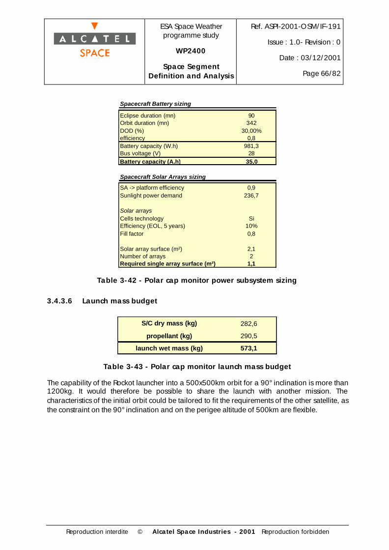
ESA Space Weatherprogramme study
WP2400
Space SegmentDefinition and Analysis
Ref. ASPI-2001-OSM/IF-191
Issue : 1.0- Revision : 0
Date : 03/12/2001
Page 66/82
Reproduction interdite © Alcatel Space Industries - 2001 Reproduction forbidden
Spacecraft Battery sizing
Eclipse duration (mn) 90Orbit duration (mn) 342DOD (%) 30,00%efficiency 0,8Battery capacity (W.h) 981,3Bus voltage (V) 28Battery capacity (A.h) 35,0
Spacecraft Solar Arrays sizing
SA -> platform efficiency 0,9Sunlight power demand 236,7
Solar arraysCells technology SiEfficiency (EOL, 5 years) 10%Fill factor 0,8
Solar array surface (m²) 2,1Number of arrays 2Required single array surface (m²) 1,1
Table 3-42 - Polar cap monitor power subsystem sizing
3.4.3.6 Launch mass budget
S/C dry mass (kg) 282,6
propellant (kg) 290,5
launch wet mass (kg) 573,1
Table 3-43 - Polar cap monitor launch mass budget
The capability of the Rockot launcher into a 500x500km orbit for a 90° inclination is more than1200kg. It would therefore be possible to share the launch with another mission. Thecharacteristics of the initial orbit could be tailored to fit the requirements of the other satellite, asthe constraint on the 90° inclination and on the perigee altitude of 500km are flexible.

ESA Space Weatherprogramme study
WP2400
Space SegmentDefinition and Analysis
Ref. ASPI-2001-OSM/IF-191
Issue : 1.0- Revision : 0
Date : 03/12/2001
Page 67/82
Reproduction interdite © Alcatel Space Industries - 2001 Reproduction forbidden
4. ELEMENT DESIGN - MEDIUM SCALE SPACESEGMENT
4.1 Combined Solar Observer - Upstream Monitor
In the medium scale space segment, the concept of data relay, which was the design driver forthe full scale space segment, is not used. Each part of the space segment is independent fromthe other satellites in terms of instrument telemetry. For this reason the solar observation andupstream monitoring instruments can be grouped on a single spacecraft at L1.
4.1.1 Payload requirements
The payload of this combined SO/UM at L1 is a consists of a reduced capability set of theinstruments of the full scale SO and UM.
WP2200-2300 ref. Instrument Mass (kg) Power (W) Telemetry (kbps)2 EUV imager 28 20 283 Magnetograph 26 25 9,54 Coronagraph 25 25 505 Halpha imager 18 20 TBD6 Soft X-ray & UV flux monitor 5 5 0,27 Radio spectrograph 12 6 0,58 EUV spectrograph 5 5 19 Solar and galactic radiation monitor 6 8 0,1
10 Solar Wind monitor 6 5 211 Thermal plasma monitor 6 8 212 Mid energy particle monitor 2 4 213 Magnetometer 1 2 0,2
Total 140 133 95,5
Table 4-1 - SO/UM payload summary

ESA Space Weatherprogramme study
WP2400
Space SegmentDefinition and Analysis
Ref. ASPI-2001-OSM/IF-191
Issue : 1.0- Revision : 0
Date : 03/12/2001
Page 68/82
Reproduction interdite © Alcatel Space Industries - 2001 Reproduction forbidden
4.1.2 Spacecraft configuration
The spacecraft configuration is driven by the solar observation instrument, that require 3 axisstabilisation and a sun-pointing attitude. The resulting configuration is comparable the theSoHO configuration except that this spacecraft has a lower launch mass.
4.1.3 System budgets
Spacecraft Mass Budget
Subsystem Mass Number Total massOBDH 20 1 20Power
PCDU 10 1 10Solar array 20 2 40
Batteries (Li-ion) 5 1 5
Structure 40 1 40Thermal 15 1 15AOCS
reaction wheels 5 4 20star trackers 3 2 6
IMU 2 2 4Sun sensors 1 2 2
CommTM antenna 8 1 8
TM electronics 25 1 25TTC equipment 7 1 7
Propulsiontanks 10 1 10
10N thrusters 0,65 16 10,4tubing 5 1 5
miscellaneous equipment 5 1 5
PayloadEUV imager 28 1 28
Magnetograph 26 1 26Coronagraph 25 1 25
Halpha imager 18 1 18Soft X-ray & UV flux monitor 5 1 5
Radio spectrograph 12 1 12EUV spectrograph 5 1 5
Solar and galactic radiation monitor 6 1 6Solar Wind monitor 6 1 6
Thermal plasma monitor 6 1 6Mid energy particle monitor 2 1 2
Magnetometer 1 1 1Total Spacecraft 372,4
Table 4-2 - SO/UM mass budget

ESA Space Weatherprogramme study
WP2400
Space SegmentDefinition and Analysis
Ref. ASPI-2001-OSM/IF-191
Issue : 1.0- Revision : 0
Date : 03/12/2001
Page 69/82
Reproduction interdite © Alcatel Space Industries - 2001 Reproduction forbidden
Spacecraft Power Budget
Subsystem Power (W)OBDH 25Power 20Thermal 15AOCS
reaction wheels 28star trackers 17
IMU 20Comm
TM electronics 150TTC 20
PayloadEUV imager 20
Magnetograph 25Coronagraph 25
Halpha imager 20Soft X-ray & UV flux monitor 5
Radio spectrograph 6EUV spectrograph 5
Solar and galactic radiation monitor 8Solar Wind monitor 5
Thermal plasma monitor 8Mid energy particle monitor 4
Magnetometer 2Total spacecraft 428
Table 4-3 - SO/UM power budget
4.1.4 Propulsion subsystem
A dedicated launch is necessary considering the expected spacecraft dry mass. The strategy issimilar to the one used for Herschel/Planck at L2 : direct launch into a transfer orbit to L1,allowing to perform only trajectory corrections during the “cruise” phase and a low delta-Vinsertion manoeuvre.
For this purpose a monopropellant propulsion subsystem is sufficient. It allows to have areasonably good performance (specific impulse of about 210s) associated with a low subsystemdry mass (only 1 low volume propellant tank).
The 10N thrusters used for stationkeeping, attitude control and wheels unloading during thespacecraft lifetime have been supposed to be enough to perform the course corrections andinsertion manoeuvres. This needs to be confirmed, and 20N thrusters might be implemented isnecessary.
The total delta-V allocation for course corrections, insertion and stationkeeping is taken to be200m/s, based on Hershel/Planck similarities. Mission analysis will be required to confirm thesevalues. A preliminary propellant budget is shown hereafter.

ESA Space Weatherprogramme study
WP2400
Space SegmentDefinition and Analysis
Ref. ASPI-2001-OSM/IF-191
Issue : 1.0- Revision : 0
Date : 03/12/2001
Page 70/82
Reproduction interdite © Alcatel Space Industries - 2001 Reproduction forbidden
Spacecraft Propellant Budget
delta V 200Isp 210Dry mass 372,4Propellant mass 37,97
Fuel N2H4density 1,00propellant volume 37,97tank diameter 0,42
Table 4-4 - SO/UM propellant budget
4.1.5 Power subsystem
The spacecraft is always in view of the sun during its operational lifetime. The spacecraft batterycapacity is not driven by the nominal operations, during which there are no eclipses, but by thelaunch and cruise phase, and by the safe mode requirements. The spacecraft might encounteran eclipse period shortly after launcher separation, depending on the ascent trajectory. Duringthe operational lifetime, possible losses of attitude control must be taken into account, duringwhich the solar arrays might not be illuminated. The batteries will have to power the spacecraftduring the time necessary to recover the sun-pointing attitude.
This preliminary sizing is for the nominal operations only, i.e. the solar arrays are the onlypower source for the platform and payload.
Spacecraft Solar Arrays sizing
SA -> platform efficiency 0,8Sunlight power demand 535,00
Solar arraysCells technology AsGaEfficiency (EOL, 11 years) 13%Fill factor 0,8
Solar array surface (m²) 3,73Number of arrays 2Required single array surface (m²) 1,87
Table 4-5 - SO/UM solar arrays sizing

ESA Space Weatherprogramme study
WP2400
Space SegmentDefinition and Analysis
Ref. ASPI-2001-OSM/IF-191
Issue : 1.0- Revision : 0
Date : 03/12/2001
Page 71/82
Reproduction interdite © Alcatel Space Industries - 2001 Reproduction forbidden
4.1.6 Launch mass budget
Launch Mass Budget
S/C dry mass 372,4
propellant 38,0
launch wet mass 410,4
Table 4-6 - Combined SO/UM launch mass budget
As was already mentioned, extensive mission analysis will be required to determine the besttrajectory for the transfer of the S/C to L1, and the launcher selection will be a consequence ofthe trajectory requirements. However the capability of the Soyuz launcher into Earth escapetrajectories is clearly sufficient for this application (C3 > 36 km²/s² for the considered launchmass).
4.2 Radiation Belt Monitors
In the medium scale space segment, the Radiation Belt Monitors instrumentation and orbitrequirements are identical to the ones for the full scale space segment (see §3.3), except thatthe WAVES B instrument is not included. The only other difference in the design is thecommunications subsystem, as in the present case the data is not relayed by the SolarObserver, but is transmitted directly to the Earth.
The impact on the satellite is a communication subsystem requiring less resources than on thefull scale RBM, as larger antennae can be used on ground, thus limiting the required RF poweron the satellite.
The baseline launch strategy, however, remains the dedicated launch option on PSLV, for theprogrammatics constraints associated with the separate ASAP5 launches already mentioned.
4.2.1 System budgets
The system budgets are derived from the full scale RBM's budgets, with the requiredmodifications on the communications subsystem.

ESA Space Weatherprogramme study
WP2400
Space SegmentDefinition and Analysis
Ref. ASPI-2001-OSM/IF-191
Issue : 1.0- Revision : 0
Date : 03/12/2001
Page 72/82
Reproduction interdite © Alcatel Space Industries - 2001 Reproduction forbidden
Spacecraft Mass Budget
Subsystem Mass Number Total massOBDH 15 1 15Power
solar arrays 8 1 8battery 10 1 10PCDU 4 1 4
Structure 100 1 100Thermal 10 1 10AOCS
star trackers 3 2 6IMU 2 2 4
sun sensors 0,5 2 1Comm
TMTC 8 1 8
Propulsiontanks 10 4 40
press tank 10 1 1010N thrusters 0,7 8 5,6
tubing 5 1 5apogee boost motor 5 1 5
miscellaneous equipment 5 1 5
PayloadThermal plasma monitor 5 1 5
Mid energy particle monitor 2 1 2Magnetometer 1,2 1 1,2
Waves A 1,3 1 1,3Neutral particle imager 3 1 3
Total Spacecraft 249,1
Table 4-7 - Medium scale RBM mass budget

ESA Space Weatherprogramme study
WP2400
Space SegmentDefinition and Analysis
Ref. ASPI-2001-OSM/IF-191
Issue : 1.0- Revision : 0
Date : 03/12/2001
Page 73/82
Reproduction interdite © Alcatel Space Industries - 2001 Reproduction forbidden
Spacecraft Power Budget
Subsystem Power (W)OBDH 15Power 10Thermal 10AOCS
star trackers 5IMU 10
CommTMTC electronics 20
PayloadThermal plasma monitor 8
Mid energy particle monitor 4Magnetometer 2
Waves A 1,2Neutral particle imager 3
Total spacecraft 88,2
Table 4-8 - Medium scale RBM power budget
4.2.2 Communication subsystem
The baseline is an S-band communication system, with a quasi-omnidirectional antenna and3W RF power. The mass of the subsystem is estimated to less than 8kg, and the powerrequirement to 20W.
An optional system could be envisaged, consisting of an X-band transponder and antenna,allowing more flexibility in the transmissions. The power requirements would be 45W (with 10WRF power) and the mass less than 10kg.
4.2.3 Power subsystem
The power subsystem is identical to the full scale RBMs, taking into account the updated powerrequirement. The new sizing is shown hereafter:
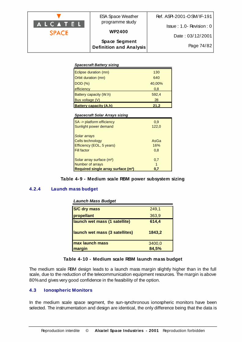
ESA Space Weatherprogramme study
WP2400
Space SegmentDefinition and Analysis
Ref. ASPI-2001-OSM/IF-191
Issue : 1.0- Revision : 0
Date : 03/12/2001
Page 74/82
Reproduction interdite © Alcatel Space Industries - 2001 Reproduction forbidden
Spacecraft Battery sizing
Eclipse duration (mn) 130Orbit duration (mn) 640
DOD (%) 40,00%efficiency 0,8Battery capacity (W.h) 592,4Bus voltage (V) 28
Battery capacity (A.h) 21,2
Spacecraft Solar Arrays sizing
SA -> platform efficiency 0,9Sunlight power demand 122,0
Solar arraysCells technology AsGaEfficiency (EOL, 5 years) 16%Fill factor 0,8
Solar array surface (m²) 0,7Number of arrays 1Required single array surface (m²) 0,7
Table 4-9 - Medium scale RBM power subsystem sizing
4.2.4 Launch mass budget
Launch Mass Budget
S/C dry mass 249,1
propellant 363,9launch wet mass (1 satellite) 614,4
launch wet mass (3 satellites) 1843,2
max launch mass 3400,0margin 84,5%
Table 4-10 - Medium scale RBM launch mass budget
The medium scale RBM design leads to a launch mass margin slightly higher than in the fullscale, due to the reduction of the telecommunication equipment resources. The margin is above80% and gives very good confidence in the feasibility of the option.
4.3 Ionospheric Monitors
In the medium scale space segment, the sun-synchronous ionospheric monitors have beenselected. The instrumentation and design are identical, the only difference being that the data is

ESA Space Weatherprogramme study
WP2400
Space SegmentDefinition and Analysis
Ref. ASPI-2001-OSM/IF-191
Issue : 1.0- Revision : 0
Date : 03/12/2001
Page 75/82
Reproduction interdite © Alcatel Space Industries - 2001 Reproduction forbidden
not transmitted through the GEO relay but directly to the ground. The communicationequipment has to be replaced with the following characteritics : mass 8kg including antenna,power 20W (3W RF). This has very little impact on the overall design and none on the launchstrategy.

ESA Space Weatherprogramme study
WP2400
Space SegmentDefinition and Analysis
Ref. ASPI-2001-OSM/IF-191
Issue : 1.0- Revision : 0
Date : 03/12/2001
Page 76/82
Reproduction interdite © Alcatel Space Industries - 2001 Reproduction forbidden
5. ELEMENT DESIGN - MINIMUM SCALE SPACESEGMENT
5.1 Solar Observer
Considering the objective of designing a cost effective minimal Solar Observer, the option ofbasing the spacecraft on a European recurrent platform will be considered here. The payloadrequirements are within the capability of the currently available or planned platforms (the massand power requirements are quite low as compared to other planned missions of theseplatforms.
Special attention will be needed, however, for the pointing requirements, that more demandingthan for most common Earth observation missions.
5.1.1 Payload requirements
WP2200-2300 ref. Instrument Mass (kg) Power (W) Telemetry (kbps)2 EUV imager 28 20 284 Coronagraph 25 25 506 Soft X-ray & UV flux monitor 5 5 0,28 EUV spectrograph 5 5 1
Total 63 55 79,2
Table 5-1 - LEO SO payload summary
5.1.2 Orbit selection
In order to maximise the sun observation time, the natural choice is a sun-synchronous dawn-dusk orbit (local time at equator crossing : 6h/18h). The altitude of the orbit has to be selectedaccording to launch constraints, platform cost minimisation and observation time maximisation.

ESA Space Weatherprogramme study
WP2400
Space SegmentDefinition and Analysis
Ref. ASPI-2001-OSM/IF-191
Issue : 1.0- Revision : 0
Date : 03/12/2001
Page 77/82
Reproduction interdite © Alcatel Space Industries - 2001 Reproduction forbidden
E c l i p s e s p a r a m e t e r s
0
1 0
2 0
3 0
4 0
5 0
6 0
0
300
600
900
1200
1500
1800
2100
2400
2700
3000
3300
3600
3900
4200
4500
4800
5100
5400
Al t i tude
E c l i p s e d u r a t i o n ( m i n ) % o f o rb i t i n ec l i pse
Figure 5-1 - LEO SO eclipses vs. altitude
The eclipse characteristics for dawn-dusk sun-synchronous orbits are plotted in table xx. Thistable shows that there are no eclipses for altitudes between 1500km and 3300km.
The capability of available (today and considering the mission horizon) low cost LEO launchersfor this kind of orbit is on the order of 1000km (Rockot, COSMOS). Moreover, selecting ahigher orbit altitude leads to an harsher radiation environment.
The baseline orbit altitude is 950km.
5.1.3 PROTEUS based Solar Observer
The PROTEUS capability for this mission can be summarised as follows
• Compatible with SSO orbits with altitudes of up to 1500km
• Compatible with inertial pointing
• Payload capability of up to 300kg, 300W
The principle of the implementation of a payload on PROTEUS is to build an independentpayload module that has a square base of 1m x 1m, which is mounted on the platform. Theplatform design itself is recurrent and independent of the payload.
The aspects that would have to be investigated more particularly in an accommodation studyare:
• Thermal design of the payload module
• AOCS, pointing precision, stability

ESA Space Weatherprogramme study
WP2400
Space SegmentDefinition and Analysis
Ref. ASPI-2001-OSM/IF-191
Issue : 1.0- Revision : 0
Date : 03/12/2001
Page 78/82
Reproduction interdite © Alcatel Space Industries - 2001 Reproduction forbidden
• Downlink strategy and equipment
5.2 Upstream Monitor
In the minimum scale system scenario, the Upstream Monitor is identical to the full scale design.See §3.2.
5.3 Radiation Belt Monitor
In this scenario there is only one RBM, and the following differences can be identified withrespect to the full scale RBM design
• There is no more need for a precise orbit orientation, as there is only one "petal" instead ofthree that had to be evenly spaced
• The data transfer does not go through a GEO relay as in the full scale option, therefore thecommunication equipment will be lighter.
• The WAVES B instrument is not included.
Under these assumptions a cost effective launch and design can be baselined : Ariane ASAP5micro.
The design is very similar to the one presented for the full-scale RBM, in §3.3.4. The onlydifference is the communication equipment, as the observation data is transmitted directly to theground, instead of the GEO relay. (Comm subsystem characteristics in this case : 8kg, 20W).
6. POSSIBLE ADDITIONS AND FUTUREDEVELOPMENTS
6.1 Magnetospheric constellation
A total of 32 small satellites are distributed into several orbits, as discussed below.

ESA Space Weatherprogramme study
WP2400
Space SegmentDefinition and Analysis
Ref. ASPI-2001-OSM/IF-191
Issue : 1.0- Revision : 0
Date : 03/12/2001
Page 79/82
Reproduction interdite © Alcatel Space Industries - 2001 Reproduction forbidden
Orbital characteristics
• Equatorial highly elliptical orbits
4 orbits with inclination 0°, perigee 2.5 Re, apogee 20 Re
line of apsides separated by 90°
6 evenly spaced satellites per orbit
• Polar orbit
1 orbit with inclination 90°, perigee 2.5 Re, apogee 15 Re
6 evenly spaced satellites in this orbit
• Molniya-type orbit
1 orbit with inclination 63.4°, perigee 2 Re, apogee 8 Re
2 evenly spaced satellites in this orbit
This is very similar to the SWARM (Space Weather Advanced Research Mission) that wasproposed to ESA for a F2/F3 Flexi-Mission.
6.2 Solar wind monitor upstream of L1
A possibility of placing a solar wind monitor upstream of L1 using solar sail technologies can beconsidered.
To have a significant advantage over an L1 Upstream Monitor, such a spacecraft shouldsignificantly increase the warning time. We will here consider a monitor 3 million kilometersfrom the Earth, which doubles the warning time as compared to an L1 monitor.
The idea is to create an artificial libration point closer to the sun by adding an acceleration tothe ones whose equilibrium leads to the existence of L1. The solar radiation pressure on a solarsail is the source of this acceleration.
For a distance of 3 million km, the necessary S/m ratio is on the order of 47, meaning that a4700m² sail is required for a 100kg spacecraft.
The most promising technologies for future solar sails are inflatable structures, which allow tohave very large surfaces with a very low mass (basically the soft envelope and the gas used forinflation) .
However, considering the current state of development of solar sail technologies, this option willnot be considered in the first system implementation that will be proposed. It might contribute toan extension of the system capacity and performance at a later stage.

ESA Space Weatherprogramme study
WP2400
Space SegmentDefinition and Analysis
Ref. ASPI-2001-OSM/IF-191
Issue : 1.0- Revision : 0
Date : 03/12/2001
Page 80/82
Reproduction interdite © Alcatel Space Industries - 2001 Reproduction forbidden
6.3 Solar wind monitor downstream of L1
The principle is the same as for the spacecraft upstream of L1. However a solar sail cannot beused here as the artificial acceleration required is directed towards the sun. This spacecraft willhave to rely on another propulsion device. As the propulsion needs to be low thrust andcontinuous, electric propulsion would be a natural choice.
A characteristic of electric propulsion systems is that they have a very high specific impulse (i.e.are very efficient propellant-wise) but that they require very high amounts of power to operate.
The main design challenge is expected to be the high power required by electric propulsionrather than the propellant mass, as it is contradictory to have a high power generationcapability on a spacecraft that would otherwise be of the minisat or microsat class. Thereforethe propulsion type shall have a high thrust/power ratio in addition of a high specific impulse.
We will examine here Arcjet, Hall Effect and Ion thrusters, and a spacecraft dry mass of 200 kg.
The assumptions and results are summarised in the following tables:
Propulsion type Arcjet Hall Effect Ion thrusters
Electric propulsion Isp (s) 480 1600 2500
Electric propulsion thrust/power ratio (mN/kW) 130 55 35
Electric propulsion specific mass (kg/kW) 3.5 7 25
Table 6-1 - Electric propulsion systems characteristics
These values are typical values for electric propulsion systems, in order to derive orders ofmagnitude. However there are variations depending on the thrust range required. A more indepth study would take these variations into account.
The lifetime has to be selected so that it is compatible with the "operational" characteristic of theoverall system:
- If it has only one thruster, the spacecraft will have to be replaced at the end of life
- If it has several thrusters, they can be used alternatively, but at the expense of the spacecraftdry mass.
For a two years lifetime, the results are presented in the following table.

ESA Space Weatherprogramme study
WP2400
Space SegmentDefinition and Analysis
Ref. ASPI-2001-OSM/IF-191
Issue : 1.0- Revision : 0
Date : 03/12/2001
Page 81/82
Reproduction interdite © Alcatel Space Industries - 2001 Reproduction forbidden
ArcjetDistance from Earth (km) 1 000 000 1 100 000 1 200 000 1 300 000 1 400 000Required propellant mass (kg) 8752 2781 1042 406 131Required maximum thrust (N) 2,541 0,601 0,169 0,05 0,013Required power (kW) 19,54 4,63 1,3 0,39 0,1
Hall EffectDistance from Earth (km) 1 000 000 1 100 000 1 200 000 1 300 000 1 400 000Required propellant mass (kg) 425 249 145 78 32Required maximum thrust (N) 0,178 0,091 0,047 0,023 0,009Required power (kW) 3,23 1,65 0,86 0,42 0,16
Ion ThrustersDistance from Earth (km) 1 000 000 1 100 000 1 200 000 1 300 000 1 400 000Required propellant mass (kg) 214,96 135,98 84,01 47,48 20,43Required maximum thrust (N) 0,118 0,068 0,039 0,02 0,008Required power (kW) 3,36 1,94 1,11 0,59 0,24
Table 6-2 - UM using electric propulsion
The thrust, power and mass results are directly proportional to the spacecraft dry mass.Therefore the problem has to be examined in terms of power/mass ratio (A spacecraft able toproduce several kW will be more massive, and therefore will require more thrust and propellantto maintain its position, and finally more power). The limitation of this approach is that as thespacecraft becomes more massive, a higher proportion of its mass is dedicated to powergeneration.
The demonstrated lifetimes for electric propulsion systems are today on the order of 10000hours, or about 1.2 years. Such a lifetime for an operational solar wind monitor is notacceptable as it would lead to building and launching a spacecraft each year. However theelectric propulsion technologies are evolving rapidly, and sufficient lifetime and performancecapabilities might become available soon.
Considering a 2 years mission, a spacecraft 100,000 km downstream of L1 (1,400,000 kmfrom the Earth) using Hall Effect thrusters seems a reasonable option. It would require about160W dedicated to propulsion (to be added to the payload and platform requirement), andabout 32 kg of propellant (Xenon).
A spacecraft operational lifetime of more than two years will definitely require several electricthrusters due to lifetime issues.
It must be noted that the presented results suppose a constant thrust during the spacecraftlifetime. It might be possible to have an electric thruster operation only during givenstationkeeping periods (a higher thrust would then be needed). However determining the actualthrust duration over a given lifetime requires extensive mission analysis that could not beperformed here. This would an issue to be addressed in case this option is studied further at alater stage.

ESA Space Weatherprogramme study
WP2400
Space SegmentDefinition and Analysis
Ref. ASPI-2001-OSM/IF-191
Issue : 1.0- Revision : 0
Date : 03/12/2001
Page 82/82
Reproduction interdite © Alcatel Space Industries - 2001 Reproduction forbidden
Considering the complexity of the implementation of a monitor downstream of L1, and theoverall system complexity, this option is not considered a priority and will not appear in thebaseline proposal. However it might be considered for an addition to the baseline system in afuture time.