esfr cold storage manual a4 ud march 2008
TRANSCRIPT
ESFR Pre-primed Single Interlock Preaction Cold Storage System
Technical Manual for Design, Installation,Operation and Maintenance
March 7, 2008 Form No. F_122807
Page II
TECHNICAL DATA
The Viking Corporation, 210 N Industrial Park Road, Hastings MI 49058Telephone: 269-945-9501 Technical Services 877-384-5464 Fax: 269-945-4495 Email: [email protected]
ESFR PRE-PRIMED SINGLE INTERLOCK PREACTION COLD STORAGE SYSTEM
March 07, 2008
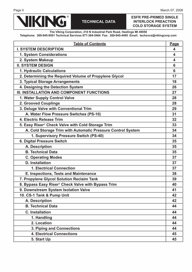
Table of Contents PageI. SYSTEM DESCRIPTION 4
1. System Considerations 42. System Makeup 4
II. SYSTEM DESIGN 61. Hydraulic Calculations 62. Determining the Required Volume of Propylene Glycol 173. Typical Storage Arrangements 184. Designing the Detection System 26
III. INSTALLATION AND COMPONENT FUNCTIONS 271. Water Supply Control Valve 282. Grooved Couplings 283. Deluge Valve with Conventional Trim 29
A. Water Flow Pressure Switches (PS-10) 314. Electric Release Trim 325. Easy Riser® Check Valve with Cold Storage Trim 33
A. Cold Storage Trim with Automatic Pressure Control System 341. Supervisory Pressure Switch (PS-40) 34
6. Digital Pressure Switch 35A. Description 35B. Technical Data 35C. Operating Modes 37D. Installation 37
1. Electrical Connection 37E. Inspections, Tests and Maintenance 38
7. Propylene Glycol Solution Reclaim Tank 398. Bypass Easy Riser® Check Valve with Bypass Trim 409. Downstream System Isolation Valve 4110. CS-1 Tank & Pump Unit 42
A. Description 42B. Technical Data 44C. Installation 44
1. Handling 442. Location 443. Piping and Connections 444. Electrical Connections 455. Start Up 45
Page IIIMarch 07, 2008
TECHNICAL DATAESFR PRE-PRIMED SINGLE
INTERLOCK PREACTION COLD STORAGE SYSTEM
The Viking Corporation, 210 N Industrial Park Road, Hastings MI 49058Telephone: 269-945-9501 Technical Services 877-384-5464 Fax: 269-945-4495 Email: [email protected]
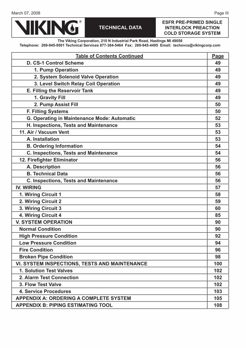
Table of Contents Continued PageD. CS-1 Control Scheme 49
1. Pump Operation 492. System Solenoid Valve Operation 493. Level Switch Relay Coil Operation 49
E. Filling the Reservoir Tank 491. Gravity Fill 492. Pump Assist Fill 50
F. Filling Systems 50G. Operating in Maintenance Mode: Automatic 52H. Inspections, Tests and Maintenance 53
11. Air / Vacuum Vent 53A. Installation 53B. Ordering Information 54C. Inspections, Tests and Maintenance 54
12. Firefi ghter Eliminator 56A. Description 56B. Technical Data 56C. Inspections, Tests and Maintenance 56
IV. WIRING 571. Wiring Circuit 1 582. Wiring Circuit 2 593. Wiring Circuit 3 604. Wiring Circuit 4 85
V. SYSTEM OPERATION 90Normal Condition 90High Pressure Condition 92Low Pressure Condition 94Fire Condition 96Broken Pipe Condition 98
VI. SYSTEM INSPECTIONS, TESTS AND MAINTENANCE 1001. Solution Test Valves 1022. Alarm Test Connection 1023. Flow Test Valve 1024. Service Procedures 103
APPENDIX A: ORDERING A COMPLETE SYSTEM 105APPENDIX B: PIPING ESTIMATING TOOL 108
Page 4
TECHNICAL DATA
The Viking Corporation, 210 N Industrial Park Road, Hastings MI 49058Telephone: 269-945-9501 Technical Services 877-384-5464 Fax: 269-945-4495 Email: [email protected]
ESFR PRE-PRIMED SINGLE INTERLOCK PREACTION COLD STORAGE SYSTEM
March 07, 2008
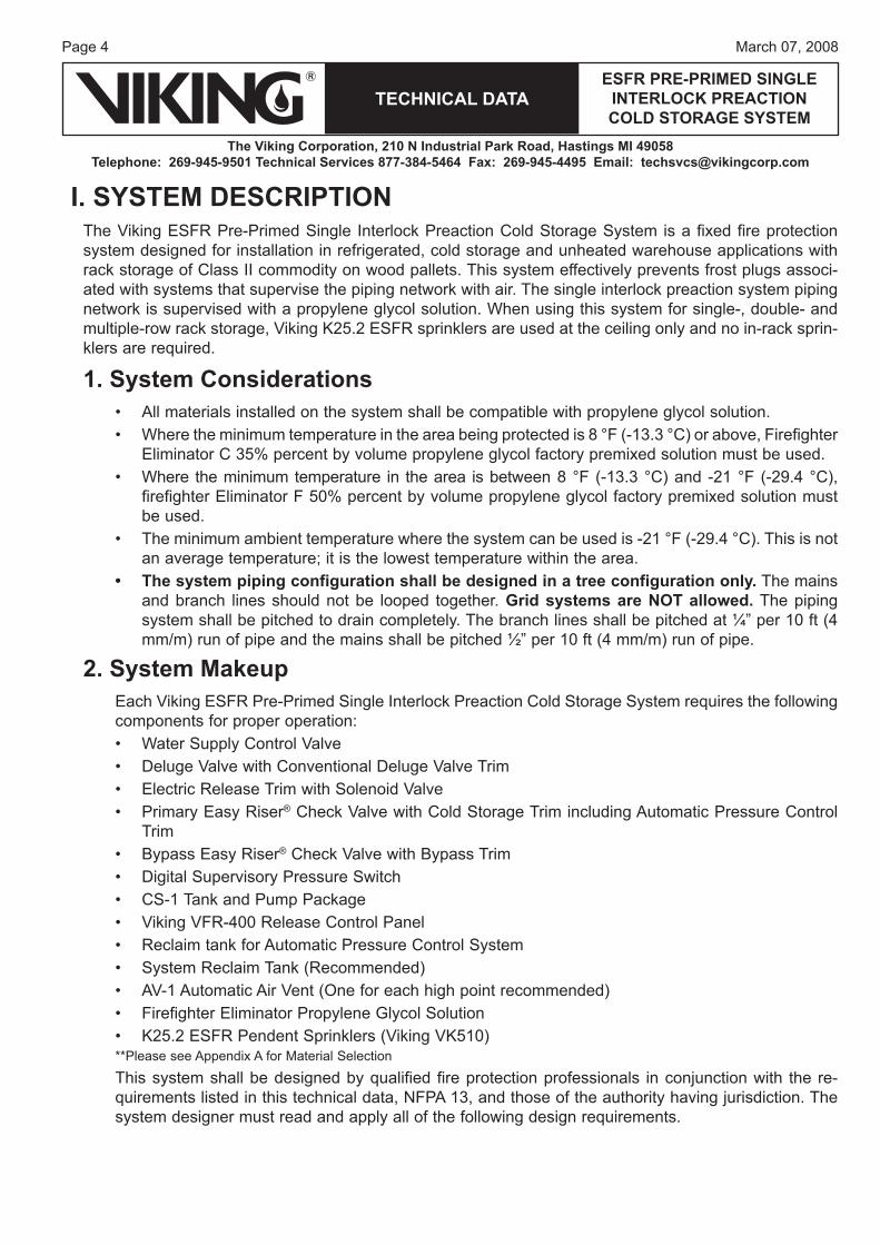
I. SYSTEM DESCRIPTIONThe Viking ESFR Pre-Primed Single Interlock Preaction Cold Storage System is a fixed fire protection system designed for installation in refrigerated, cold storage and unheated warehouse applications with rack storage of Class II commodity on wood pallets. This system effectively prevents frost plugs associ-ated with systems that supervise the piping network with air. The single interlock preaction system piping network is supervised with a propylene glycol solution. When using this system for single-, double- and multiple-row rack storage, Viking K25.2 ESFR sprinklers are used at the ceiling only and no in-rack sprin-klers are required.
1. System ConsiderationsAll materials installed on the system shall be compatible with propylene glycol solution.Where the minimum temperature in the area being protected is 8 °F (-13.3 °C) or above, Firefighter Eliminator C 35% percent by volume propylene glycol factory premixed solution must be used.Where the minimum temperature in the area is between 8 °F (-13.3 °C) and -21 °F (-29.4 °C), firefighter Eliminator F 50% percent by volume propylene glycol factory premixed solution must be used.The minimum ambient temperature where the system can be used is -21 °F (-29.4 °C). This is not an average temperature; it is the lowest temperature within the area.The system piping configuration shall be designed in a tree configuration only. The mains and branch lines should not be looped together. Grid systems are NOT allowed. The piping system shall be pitched to drain completely. The branch lines shall be pitched at ¼” per 10 ft (4 mm/m) run of pipe and the mains shall be pitched ½” per 10 ft (4 mm/m) run of pipe.
2. System MakeupEach Viking ESFR Pre-Primed Single Interlock Preaction Cold Storage System requires the following components for proper operation:
Water Supply Control ValveDeluge Valve with Conventional Deluge Valve Trim Electric Release Trim with Solenoid ValvePrimary Easy Riser® Check Valve with Cold Storage Trim including Automatic Pressure Control TrimBypass Easy Riser® Check Valve with Bypass TrimDigital Supervisory Pressure SwitchCS-1 Tank and Pump PackageViking VFR-400 Release Control PanelReclaim tank for Automatic Pressure Control SystemSystem Reclaim Tank (Recommended)AV-1 Automatic Air Vent (One for each high point recommended)Firefighter Eliminator Propylene Glycol SolutionK25.2 ESFR Pendent Sprinklers (Viking VK510)
**Please see Appendix A for Material Selection
This system shall be designed by qualified fire protection professionals in conjunction with the re-quirements listed in this technical data, NFPA 13, and those of the authority having jurisdiction. The system designer must read and apply all of the following design requirements.
••
•
•
•
••••
•••••••••
Page 5March 07, 2008
TECHNICAL DATAESFR PRE-PRIMED SINGLE
INTERLOCK PREACTION COLD STORAGE SYSTEM
The Viking Corporation, 210 N Industrial Park Road, Hastings MI 49058Telephone: 269-945-9501 Technical Services 877-384-5464 Fax: 269-945-4495 Email: [email protected]
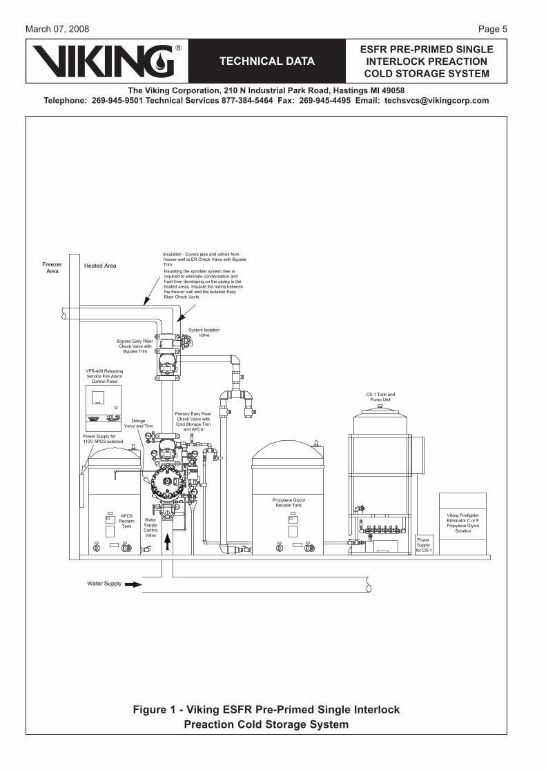
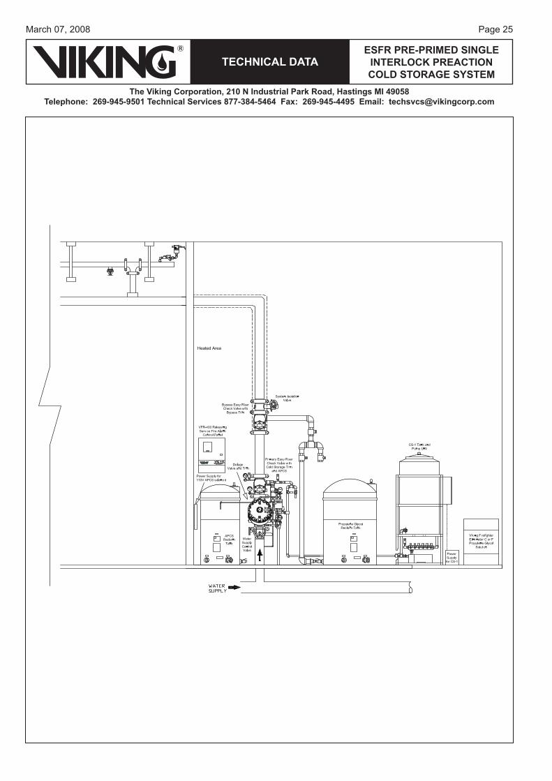
Figure 1 - Viking ESFR Pre-Primed Single Interlock Preaction Cold Storage System
Page 6
TECHNICAL DATA
The Viking Corporation, 210 N Industrial Park Road, Hastings MI 49058Telephone: 269-945-9501 Technical Services 877-384-5464 Fax: 269-945-4495 Email: [email protected]
ESFR PRE-PRIMED SINGLE INTERLOCK PREACTION COLD STORAGE SYSTEM
March 07, 2008
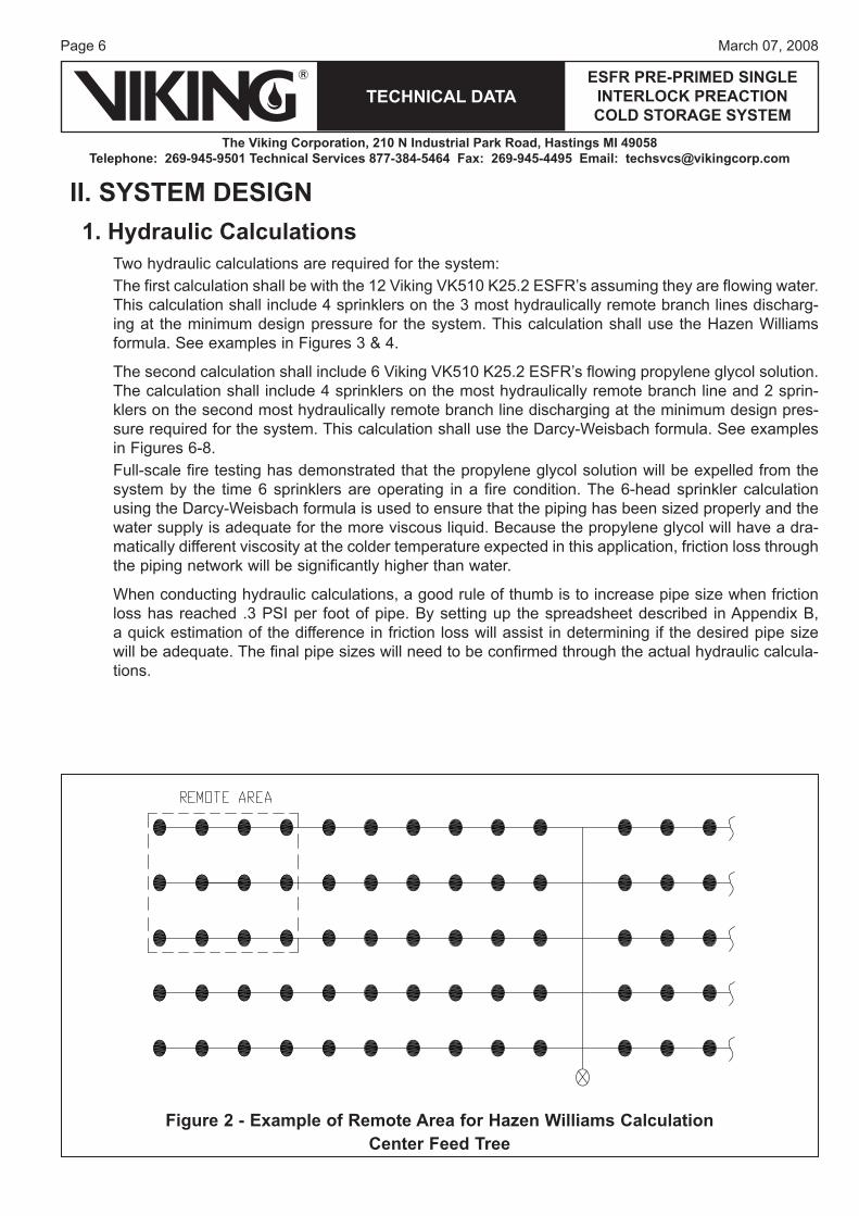
II. SYSTEM DESIGN1. Hydraulic Calculations
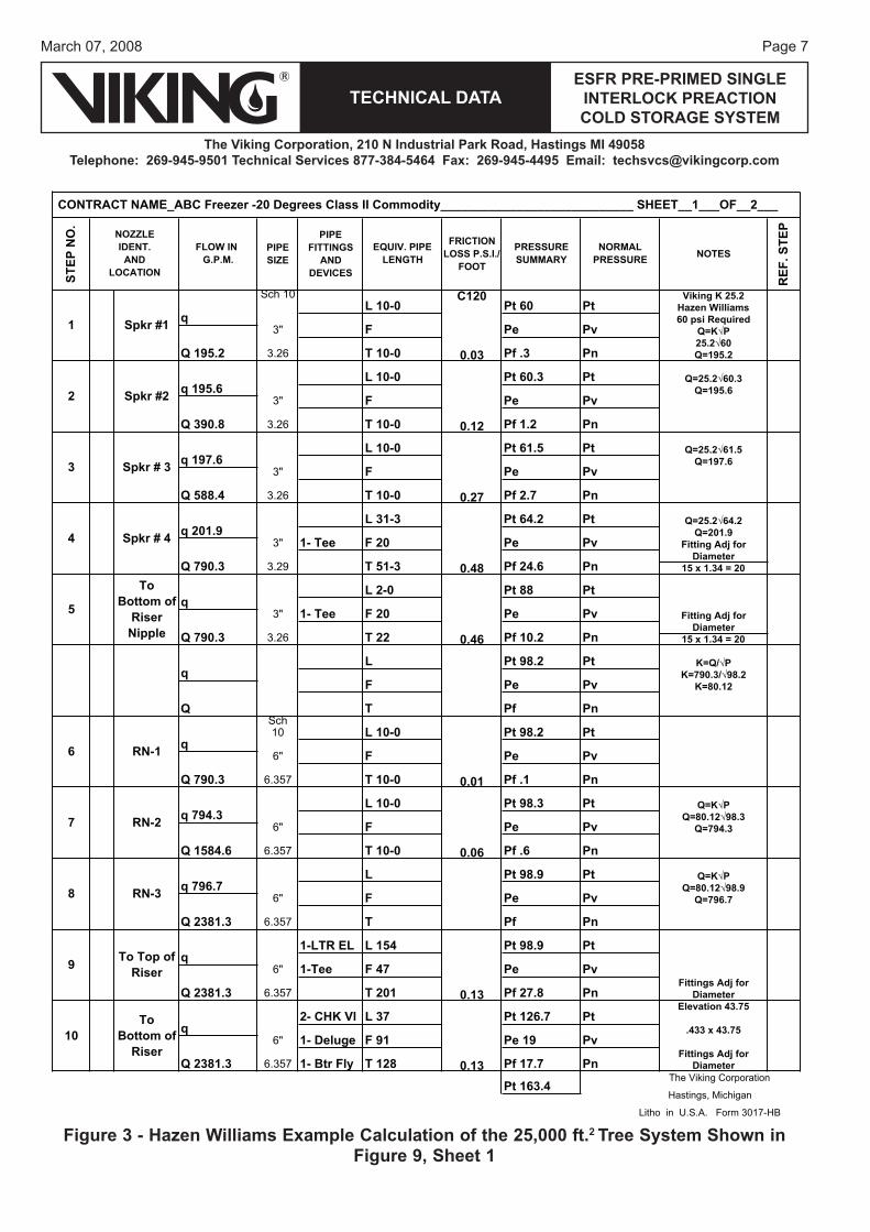
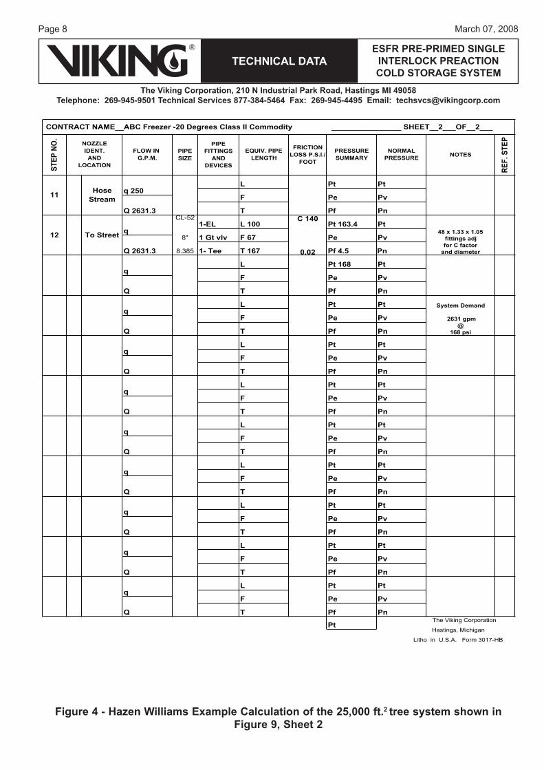
Two hydraulic calculations are required for the system:The first calculation shall be with the 12 Viking VK510 K25.2 ESFR’s assuming they are flowing water. This calculation shall include 4 sprinklers on the 3 most hydraulically remote branch lines discharg-ing at the minimum design pressure for the system. This calculation shall use the Hazen Williams formula. See examples in Figures 3 & 4.
The second calculation shall include 6 Viking VK510 K25.2 ESFR’s flowing propylene glycol solution. The calculation shall include 4 sprinklers on the most hydraulically remote branch line and 2 sprin-klers on the second most hydraulically remote branch line discharging at the minimum design pres-sure required for the system. This calculation shall use the Darcy-Weisbach formula. See examples in Figures 6-8.Full-scale fire testing has demonstrated that the propylene glycol solution will be expelled from the system by the time 6 sprinklers are operating in a fire condition. The 6-head sprinkler calculation using the Darcy-Weisbach formula is used to ensure that the piping has been sized properly and the water supply is adequate for the more viscous liquid. Because the propylene glycol will have a dra-matically different viscosity at the colder temperature expected in this application, friction loss through the piping network will be significantly higher than water.
When conducting hydraulic calculations, a good rule of thumb is to increase pipe size when friction loss has reached .3 PSI per foot of pipe. By setting up the spreadsheet described in Appendix B, a quick estimation of the difference in friction loss will assist in determining if the desired pipe size will be adequate. The final pipe sizes will need to be confirmed through the actual hydraulic calcula-tions.
Figure 2 - Example of Remote Area for Hazen Williams CalculationCenter Feed Tree
Page 7March 07, 2008
TECHNICAL DATAESFR PRE-PRIMED SINGLE
INTERLOCK PREACTION COLD STORAGE SYSTEM
The Viking Corporation, 210 N Industrial Park Road, Hastings MI 49058Telephone: 269-945-9501 Technical Services 877-384-5464 Fax: 269-945-4495 Email: [email protected]
STEP
NO
.
PIPESIZE
PIPEFITTINGS
ANDDEVICES
FRICTIONLOSS P.S.I./
FOOTNOTES
REF
.STE
P
Sch 10 C120 Viking K 25.2Hazen Williams60 psi Required
3" Q=K√P25.2√60
3.26 0.03 Q=195.2
Q=25.2√60.3Q=195.6
3"
3.26 0.12
Q=25.2√61.5Q=197.6
3"
3.26 0.27
Q=25.2√64.2Q=201.9
3" Fitting Adj for Diameter
3.29 0.48 15 x 1.34 = 20
3" Fitting Adj for Diameter
3.26 0.46 15 x 1.34 = 20
K=Q/√PK=790.3/√98.2
K=80.12
Sch10
6"
6.357 0.01
Q=K√PQ=80.12√98.3
6" Q=794.3
6.357 0.06
Q=K√PQ=80.12√98.9
6" Q=796.7
6.357
6"Fittings Adj for
6.357 0.13 DiameterElevation 43.75
.433 x 43.756"
Fittings Adj for 6.357 0.13 Diameter
Pt 126.7 Pt
Pe 19 Pv
Pf 17.7 Pn
F 91
Pt 163.4 The Viking Corporation
Hastings, Michigan
Litho in U.S.A. Form 3017-HB
1- Btr Fly T 128
10To
Bottom of Riser
q
Q 2381.3
2- CHK Vl L 37
1- Deluge
F 47
Pt 98.9 Pt
Pe Pv
Pf 27.8 PnT 201
9 To Top of Riser
q
Q 2381.3
1-LTR EL L 154
1-Tee
F
Pt 98.9 Pt
Pe Pv
Pf PnT
8 RN-3 q 796.7
Q 2381.3
L
F
Pt 98.3 Pt
Pe Pv
Pf .6 PnT 10-0
7 RN-2 q 794.3
Q 1584.6
L 10-0
F
Pt 98.2 Pt
Pe Pv
Pf .1 PnT 10-0
6 RN-1 q
Q 790.3
L 10-0
fPTQ
CONTRACT NAME_ABC Freezer -20 Degrees Class II Commodity____________________________ SHEET__1___OF__2___
2 Spkr #2 q 195.6L 10-0
1 Spkr #1 q
Q 195.2
Q 390.8
Pe Pv
Pf 1.2
3 Spkr # 3 q 197.6
Q 588.4
Pn
Pv
Pf 2.7 Pn
Pt 61.5 Pt
Pe
Pt 60.3 Pt
4 Spkr # 4 q 201.9
Q 790.3
1- Tee F 20
T 51-3
Pt 64.2 Pt
Pe Pv
Pf 24.6 Pn
Pv
Pn
PRESSURESUMMARY
NORMALPRESSURE
Pt 60 Pt
Pe
Pf .3
EQUIV. PIPE LENGTH
L 10-0
F
T 10-0
T 22
5
ToBottom of
RiserNipple
q
Q 790.3
L 2-0
1- Tee
L 31-3
F
T 10-0
F
L 10-0
T 10-0
NOZZLEIDENT.
ANDLOCATION
FLOW ING.P.M.
Pt
Pv
Pt 88
PeF 20
Pf 10.2
q2.89tPL
Pn
Pt
vPePF
Pn
Figure 3 - Hazen Williams Example Calculation of the 25,000 ft.2 Tree System Shown in Figure 9, Sheet 1
Page 8
TECHNICAL DATA
The Viking Corporation, 210 N Industrial Park Road, Hastings MI 49058Telephone: 269-945-9501 Technical Services 877-384-5464 Fax: 269-945-4495 Email: [email protected]
ESFR PRE-PRIMED SINGLE INTERLOCK PREACTION COLD STORAGE SYSTEM
March 07, 2008
STEP
NO.
PIPESIZE
PIPEFITTINGS
ANDDEVICES
FRICTIONLOSS P.S.I./
FOOTNOTES
REF.
STEP
CL-52 C 140
48 x 1.33 x 1.058" fittings adj
for C factor8.385 0.02 and diameter
System Demand
2631 gpm@
168 psi
Pt The Viking Corporation
Hastings, Michigan
Litho in U.S.A. Form 3017-HB
Pt
vPePF
nPfPT
tPLq
Q
Pt
vPePF
nPfPT
tPLq
Q
Pt
vPePF
nPfPT
tPLq
Q
Pt
vPePF
nPfPT
tPLq
Q
Pt
vPePF
nPfPT
tPLq
Q
Pt
vPePF
nPfPT
tPLq
Q
Pt
vPePF
nPfPT
tPLq
Q
Pt
vPePF
nPfPT
tPLq
Q
Pt
vPePF
nPfPT
861tPLq
Q
Pt
1 Gt vlv F 67 Pe Pv
1- Tee T 167 Pf 4.5 Pn
1-EL L 100 Pt 163.412 To Street q
Q 2631.3
Pt
vPePF
nPfPT
tPL11 Hose
Streamq 250
Q 2631.3
CONTRACT NAME__ABC Freezer -20 Degrees Class II Commodity ________________ SHEET__2___OF__2___
NOZZLEIDENT.AND
LOCATION
FLOW ING.P.M.
EQUIV. PIPE LENGTH
PRESSURESUMMARY
NORMALPRESSURE
Figure 4 - Hazen Williams Example Calculation of the 25,000 ft.2 tree system shown in Figure 9, Sheet 2
Page 9March 07, 2008
TECHNICAL DATAESFR PRE-PRIMED SINGLE
INTERLOCK PREACTION COLD STORAGE SYSTEM
The Viking Corporation, 210 N Industrial Park Road, Hastings MI 49058Telephone: 269-945-9501 Technical Services 877-384-5464 Fax: 269-945-4495 Email: [email protected]
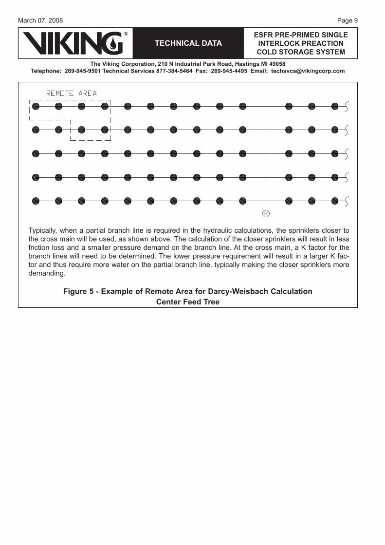
Figure 5 - Example of Remote Area for Darcy-Weisbach CalculationCenter Feed Tree
Typically, when a partial branch line is required in the hydraulic calculations, the sprinklers closer to the cross main will be used, as shown above. The calculation of the closer sprinklers will result in less friction loss and a smaller pressure demand on the branch line. At the cross main, a K factor for the branch lines will need to be determined. The lower pressure requirement will result in a larger K fac-tor and thus require more water on the partial branch line, typically making the closer sprinklers more demanding.
Page 10
TECHNICAL DATA
The Viking Corporation, 210 N Industrial Park Road, Hastings MI 49058Telephone: 269-945-9501 Technical Services 877-384-5464 Fax: 269-945-4495 Email: [email protected]
ESFR PRE-PRIMED SINGLE INTERLOCK PREACTION COLD STORAGE SYSTEM
March 07, 2008
Darcy-Weisbach Method for Calculating Friction in Piping:Most hydraulic calculation software used in the sprinkler industry today has the option for conducting the piping friction loss calculations with the Darcy-Weisbach method. The reason for conducting the additional 6 sprinkler head calculation is to verify that the available water supply pressure is adequate for the initial discharge of propylene glycol solution. The example calculations provided in Figures 6-8 illustrate the dif-ference in results that can occur when calculating for the more viscous propylene glycol solution versus the standard Hazen-Williams calculation for water illustrated in Figures 3-4. For those not familiar with the Darcy-Weisbach method below is the basic procedure that is used to conduct the calculation. This is intended only to provide the designer with an understanding of the concepts of the method. It is not practical that the calculation be done by hand as this would be much too time consuming and subject to potential errors.
The Darcy-Weisbach Formula as found in most text is written as: h= (f) (l) (v)2 / (d) (2) (g)h=friction loss (ft of head)f=friction factor (from Moody Diagram-Figure 10)l=length of pipe (ft)v=velocity (ft/sec)d=diameter of pipe (ft)g=gravitational constant (32.2 ft/sec2)
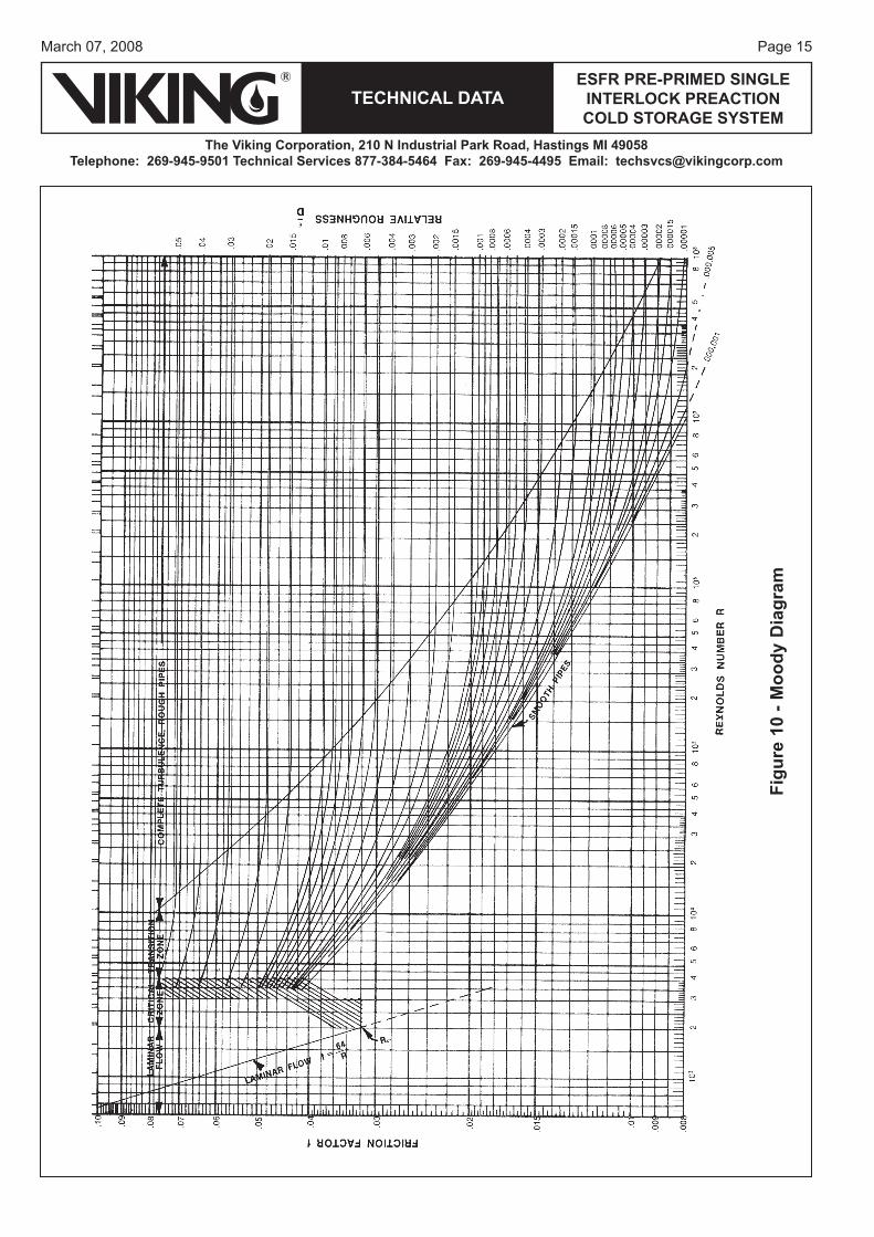
This formula can be rearranged and simplified to:When the calculated Reynolds Number (Re) is >2000 =0.000216 fLρQ2/d5 =Friction Loss (psi)When the calculated Reynolds Number (Re) is <2000 =0.000273 μLQ/d4 =Friction Loss (psi)Where:Re=50.6Qρ/dμQ=flow (gpm)ρ=density (lbs/ft3)d=internal pipe diameter (in)D=internal pipe diameter (ft)L=pipe length (ft)μ=dynamic viscosity (cps)ε= .00033 for steel pipef=friction factor, If Re > 2000, use Moody Diagram (Figure 10). If Re < 2000, f = 64/Re.Procedure:1. Calculate Reynolds Number (Re) = 50.6Qρ/dμ2. Calculate relative roughness of pipe = ε/Dε= .00033 (ft)D=internal pipe diameter (ft)3. Use Moody Diagram (Figure 10) to find “f” if Re > 2000. If Re < 2000, f = 64/Re.4. Use fiction loss in hydraulic calculation.
Page 11March 07, 2008
TECHNICAL DATAESFR PRE-PRIMED SINGLE
INTERLOCK PREACTION COLD STORAGE SYSTEM
The Viking Corporation, 210 N Industrial Park Road, Hastings MI 49058Telephone: 269-945-9501 Technical Services 877-384-5464 Fax: 269-945-4495 Email: [email protected]
STEP
NO.
PIPESIZE
PIPEFITTINGS
ANDDEVICES
FRICTIONLOSS P.S.I./
FOOTNOTES
REF.
STEP
Sch 10 Viking K 25.2Darcy Weisbach60 psi Required
3" Q=K√P25.2√60
3.26 0.08 Q=195.2
Q=25.2√60.8Q=196.4
3"
3.26 0.3
Q= 25.2√63.8Q=201.2
3"
3.26 0.61
Q=25.2√69.9Q=210.6
3" Fitting Adj for Diameter
3.26 1.03 15 x 1.34 = 20
3" Fitting Adj for Diameter
3.26 1.03 15 x 1.34 = 20
K=Q/√PK=803.4/√143.6
K=67
Sch10
6"
6.357 0.04
Q=K√PQ=45√144
6" Q=540K 45 from
6.357 Sheet 3 of 3
6"Fitting Adj for
6.357 0.1 DiameterElevation 43.75
.433 x 43.7519 psi
Fitting Adj for 0.1 Diameter
Pt 196.8 The Viking Corporation
Hastings, Michigan
Litho in U.S.A. Form 3017-HB
Pt
vPePF
nPfPT
8.691tPL10 Hose
Streamq 250
Q 1593.4
Pt
1- Deluge F 91 Pe 19 Pv
1- Btr Fly T 128 Pf 12.8 Pn
2- Chk Vl L 37 Pt 1659
ToBottom of
Riser
q
Q 1343.4
Pt
1- Tee F 47-0 Pe Pv
T 201-0 Pf 21 Pn
1- LTR EL L 154-0 Pt 1448 To Top of
Riserq
Q 1343.4
Pt
vPePF
nPfPT
441tPL7 RN-2 q 540
Q 1343.4
Pt
vPePF
T 10-0 Pf .4 Pn
L 10-0 Pt 143.66 RN-1 q
Q 803.4
Pt
vPePF
nPfPT
6.341tPLq
Q
Pt
1-Tee F 20 Pe Pv
T 22-0 Pf 22.6 Pn
L 2-0 Pt 1215
ToBottom of
RiserNipple
q
Q 803.4
Pt
1-Tee F 20 Pe Pv
T 51-3 Pf 52 Pn
L 31-3 Pt 69.94 Spkr #4 q 210.6
Q 803.4
Pt
vPePF
T 10-0 Pf 6.1 Pn
L 10-0 Pt 63.83 Spkr #3 q 201.2
Q 592.8
Pt
vPePF
T 10-0 Pf 3.0 Pn
L 10-0 Pt 60.82 Spkr #2 q 196.4
Q 391.6
Pt
vPePF
T 10-0 Pf .8 Pn
L 10-0 Pt 601 Spkr #1 q
Q 195.2
CONTRACT NAME_ABC Freezer -20 Degrees Class II Commodity___________________________ SHEET__1___OF__3___
NOZZLEIDENT.
ANDLOCATION
FLOW ING.P.M.
EQUIV. PIPE LENGTH
PRESSURESUMMARY
NORMALPRESSURE
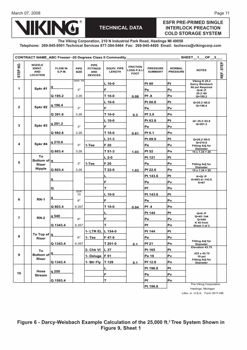
Figure 6 - Darcy-Weisbach Example Calculation of the 25,000 ft.2 Tree System Shown in Figure 9, Sheet 1
Page 12
TECHNICAL DATA
The Viking Corporation, 210 N Industrial Park Road, Hastings MI 49058Telephone: 269-945-9501 Technical Services 877-384-5464 Fax: 269-945-4495 Email: [email protected]
ESFR PRE-PRIMED SINGLE INTERLOCK PREACTION COLD STORAGE SYSTEM
March 07, 2008
STEP
NO.
PIPESIZE
PIPEFITTINGS
ANDDEVICES
FRICTIONLOSS P.S.I./
FOOTNOTES
REF.
STEP
CL-52 C 140
8" Fittings AdjAdj for C Factor
8.385 0.03 and Diameter
System Demand
1593 gpm@
203 psi
Pt The Viking Corporation
Hastings, Michigan
Litho in U.S.A. Form 3017-HB
Pt
vPePF
nPfPT
tPLq
Q
Pt
vPePF
nPfPT
tPLq
Q
Pt
vPePF
nPfPT
tPLq
Q
Pt
vPePF
nPfPT
tPLq
Q
Pt
vPePF
nPfPT
tPLq
Q
Pt
vPePF
nPfPT
tPLq
Q
Pt
vPePF
nPfPT
tPLq
Q
Pt
vPePF
nPfPT
tPLq
Q
Pt
vPePF
nPfPT
tPLq
Q
Pt
vPePF
nPfPT
02tPL 3.2q
Q
1593.4 1-Tee T 167 Pf 6.4
1- GT Vl F 67 Pe Pv
Pn
NORMALPRESSURE
11 To Street q1-El L 100 Pt 196.8 Pt 48 x 1.33 x 1.05
NOZZLEIDENT.
ANDLOCATION
FLOW IN G.P.M.
EQUIV. PIPE LENGTH
PRESSURESUMMARY
CONTRACT NAME_ABC Freezer -20 Degrees Class II Commodity__________________________ SHEET__2___OF__3___
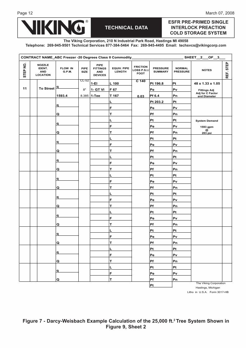
Figure 7 - Darcy-Weisbach Example Calculation of the 25,000 ft.2 Tree System Shown in Figure 9, Sheet 2
Page 13March 07, 2008
TECHNICAL DATAESFR PRE-PRIMED SINGLE
INTERLOCK PREACTION COLD STORAGE SYSTEM
The Viking Corporation, 210 N Industrial Park Road, Hastings MI 49058Telephone: 269-945-9501 Technical Services 877-384-5464 Fax: 269-945-4495 Email: [email protected]
STEP
NO.
PIPESIZE
PIPEFITTINGS
ANDDEVICES
FRICTIONLOSS P.S.I./
FOOTNOTES
REF.
STEP
Sch10 Q=K√P
Q=25.2√603" Q=195.2
3.26 0.08
Q=K√PQ=25.2√60.8
3" Q=195.2Fitting Adj for
3.26 retemaiD3.0
K=Q/√PK=391.6/√75.7
K=45
Pt The Viking Corporation
Hastings, Michigan
Litho in U.S.A. Form 3017-HB
Pt
Pf Pn
vPePF
tPLq
TQ
Pt
vPePF
nPfPT
tPLq
Q
Pt
vPePF
nPfPT
tPLq
Q
Pt
vPePF
nPfPT
tPLq
Q
Pt
vPePF
nPfPT
tPLq
Q
Pt
vPePF
nPfPT
tPLq
Q
Pt
vPePF
nPfPT
tPLq
Q
Pt
vPePF
nPfPT
tPLq
Q
Pt
vPePF
nPfPT
7.57tPLq
Q
Pt
1-Tee F 20-0 Pe Pv
T 48-9 Pf 14.9 Pn
L 28-9 Pt 60.813 Spkr#6 q 196.4
Q 391.6
8.fP0-01T2.591Q
vPePF
Pn
NORMALPRESSURE
12 Spkr #5 qL 10-0 Pt 60 Pt
NOZZLEIDENT.
ANDLOCATION
FLOW IN G.P.M.
EQUIV. PIPE LENGTH
PRESSURESUMMARY
CONTRACT NAME__ABC Freezer -20 Degrees Class II Commodity___________________________ SHEET__3___OF__3___
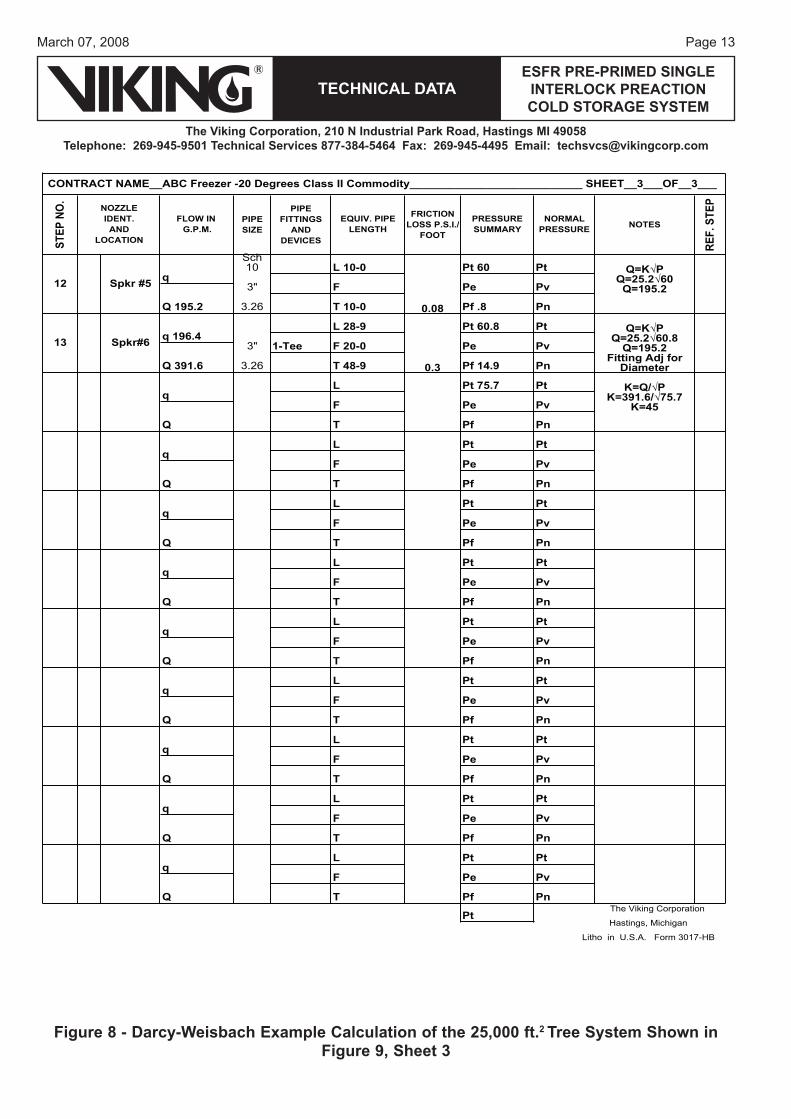
Figure 8 - Darcy-Weisbach Example Calculation of the 25,000 ft.2 Tree System Shown in Figure 9, Sheet 3
Page 14
TECHNICAL DATA
The Viking Corporation, 210 N Industrial Park Road, Hastings MI 49058Telephone: 269-945-9501 Technical Services 877-384-5464 Fax: 269-945-4495 Email: [email protected]
ESFR PRE-PRIMED SINGLE INTERLOCK PREACTION COLD STORAGE SYSTEM
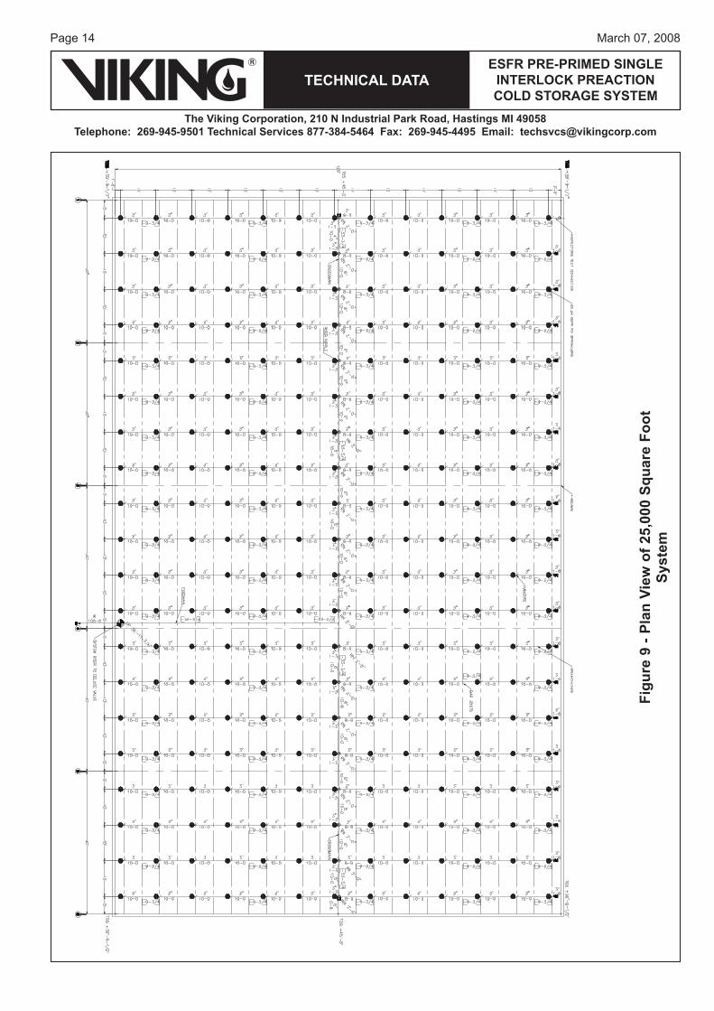
March 07, 2008
Figu
re 9
- Pl
an V
iew
of 2
5,00
0 Sq
uare
Foo
t Sy
stem
Page 15March 07, 2008
TECHNICAL DATAESFR PRE-PRIMED SINGLE
INTERLOCK PREACTION COLD STORAGE SYSTEM
The Viking Corporation, 210 N Industrial Park Road, Hastings MI 49058Telephone: 269-945-9501 Technical Services 877-384-5464 Fax: 269-945-4495 Email: [email protected]
Figu
re 1
0 - M
oody
Dia
gram
Page 16
TECHNICAL DATA
The Viking Corporation, 210 N Industrial Park Road, Hastings MI 49058Telephone: 269-945-9501 Technical Services 877-384-5464 Fax: 269-945-4495 Email: [email protected]
ESFR PRE-PRIMED SINGLE INTERLOCK PREACTION COLD STORAGE SYSTEM
March 07, 2008
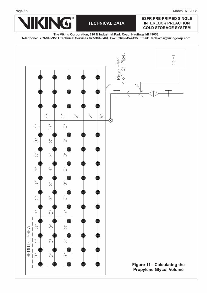
Figure 11 - Calculating the Propylene Glycol Volume
Page 17March 07, 2008
TECHNICAL DATAESFR PRE-PRIMED SINGLE
INTERLOCK PREACTION COLD STORAGE SYSTEM
The Viking Corporation, 210 N Industrial Park Road, Hastings MI 49058Telephone: 269-945-9501 Technical Services 877-384-5464 Fax: 269-945-4495 Email: [email protected]
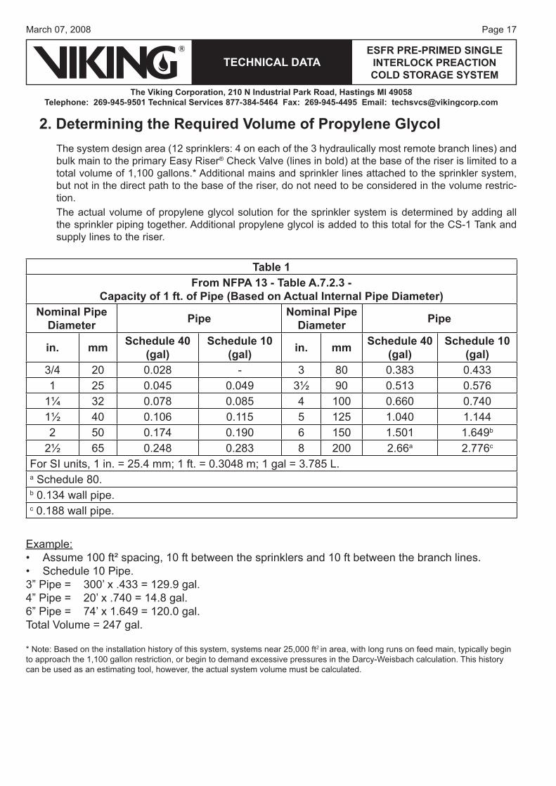
2. Determining the Required Volume of Propylene Glycol
Table 1From NFPA 13 - Table A.7.2.3 -
Capacity of 1 ft. of Pipe (Based on Actual Internal Pipe Diameter)Nominal Pipe
Diameter Pipe Nominal Pipe Diameter Pipe
in. mm Schedule 40 (gal)
Schedule 10 (gal) in. mm Schedule 40
(gal)Schedule 10
(gal)3/4 20 0.028 - 3 80 0.383 0.4331 25 0.045 0.049 3½ 90 0.513 0.576
1¼ 32 0.078 0.085 4 100 0.660 0.7401½ 40 0.106 0.115 5 125 1.040 1.1442 50 0.174 0.190 6 150 1.501 1.649b
2½ 65 0.248 0.283 8 200 2.66a 2.776c
For SI units, 1 in. = 25.4 mm; 1 ft. = 0.3048 m; 1 gal = 3.785 L.a Schedule 80.b 0.134 wall pipe.c 0.188 wall pipe.
Example:Assume 100 ft² spacing, 10 ft between the sprinklers and 10 ft between the branch lines.Schedule 10 Pipe.
3” Pipe = 300’ x .433 = 129.9 gal.4” Pipe = 20’ x .740 = 14.8 gal.6” Pipe = 74’ x 1.649 = 120.0 gal.Total Volume = 247 gal.
* Note: Based on the installation history of this system, systems near 25,000 ft2 in area, with long runs on feed main, typically begin to approach the 1,100 gallon restriction, or begin to demand excessive pressures in the Darcy-Weisbach calculation. This history can be used as an estimating tool, however, the actual system volume must be calculated.
••
The system design area (12 sprinklers: 4 on each of the 3 hydraulically most remote branch lines) and bulk main to the primary Easy Riser® Check Valve (lines in bold) at the base of the riser is limited to a total volume of 1,100 gallons.* Additional mains and sprinkler lines attached to the sprinkler system, but not in the direct path to the base of the riser, do not need to be considered in the volume restric-tion.The actual volume of propylene glycol solution for the sprinkler system is determined by adding all the sprinkler piping together. Additional propylene glycol is added to this total for the CS-1 Tank and supply lines to the riser.
Page 18
TECHNICAL DATA
The Viking Corporation, 210 N Industrial Park Road, Hastings MI 49058Telephone: 269-945-9501 Technical Services 877-384-5464 Fax: 269-945-4495 Email: [email protected]
ESFR PRE-PRIMED SINGLE INTERLOCK PREACTION COLD STORAGE SYSTEM
March 07, 2008
Figure 12 - Single Row Rack Storage Figure 13 - Double Row Rack Storage
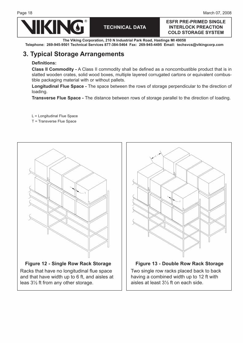
3. Typical Storage ArrangementsDefinitions:Class II Commodity - A Class II commodity shall be defined as a noncombustible product that is in slatted wooden crates, solid wood boxes, multiple layered corrugated cartons or equivalent combus-tible packaging material with or without pallets.Longitudinal Flue Space - The space between the rows of storage perpendicular to the direction of loading.Transverse Flue Space - The distance between rows of storage parallel to the direction of loading.
L = Longitudinal Flue SpaceT = Transverse Flue Space
Racks that have no longitudinal fl ue space and that have width up to 6 ft, and aisles at leas 3½ ft from any other storage.
Two single row racks placed back to back having a combined width up to 12 ft with aisles at least 3½ ft on each side.
Page 19March 07, 2008
TECHNICAL DATAESFR PRE-PRIMED SINGLE
INTERLOCK PREACTION COLD STORAGE SYSTEM
The Viking Corporation, 210 N Industrial Park Road, Hastings MI 49058Telephone: 269-945-9501 Technical Services 877-384-5464 Fax: 269-945-4495 Email: [email protected]
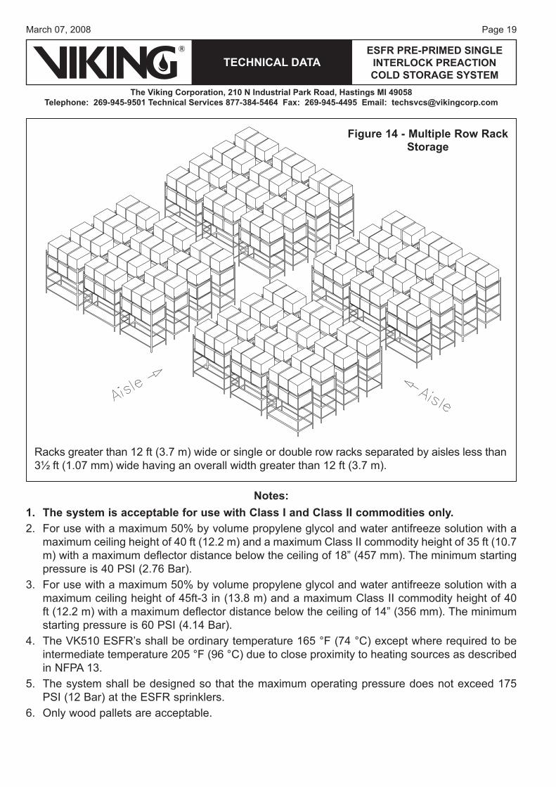
Notes:The system is acceptable for use with Class I and Class II commodities only. For use with a maximum 50% by volume propylene glycol and water antifreeze solution with a maximum ceiling height of 40 ft (12.2 m) and a maximum Class II commodity height of 35 ft (10.7 m) with a maximum deflector distance below the ceiling of 18” (457 mm). The minimum starting pressure is 40 PSI (2.76 Bar).For use with a maximum 50% by volume propylene glycol and water antifreeze solution with a maximum ceiling height of 45ft-3 in (13.8 m) and a maximum Class II commodity height of 40 ft (12.2 m) with a maximum deflector distance below the ceiling of 14” (356 mm). The minimum starting pressure is 60 PSI (4.14 Bar).The VK510 ESFR’s shall be ordinary temperature 165 °F (74 °C) except where required to be intermediate temperature 205 °F (96 °C) due to close proximity to heating sources as described in NFPA 13.The system shall be designed so that the maximum operating pressure does not exceed 175 PSI (12 Bar) at the ESFR sprinklers.Only wood pallets are acceptable.
1.2.
3.
4.
5.
6.
Figure 14 - Multiple Row Rack Storage
Racks greater than 12 ft (3.7 m) wide or single or double row racks separated by aisles less than 3½ ft (1.07 mm) wide having an overall width greater than 12 ft (3.7 m).
Page 20
TECHNICAL DATA
The Viking Corporation, 210 N Industrial Park Road, Hastings MI 49058Telephone: 269-945-9501 Technical Services 877-384-5464 Fax: 269-945-4495 Email: [email protected]
ESFR PRE-PRIMED SINGLE INTERLOCK PREACTION COLD STORAGE SYSTEM
March 07, 2008
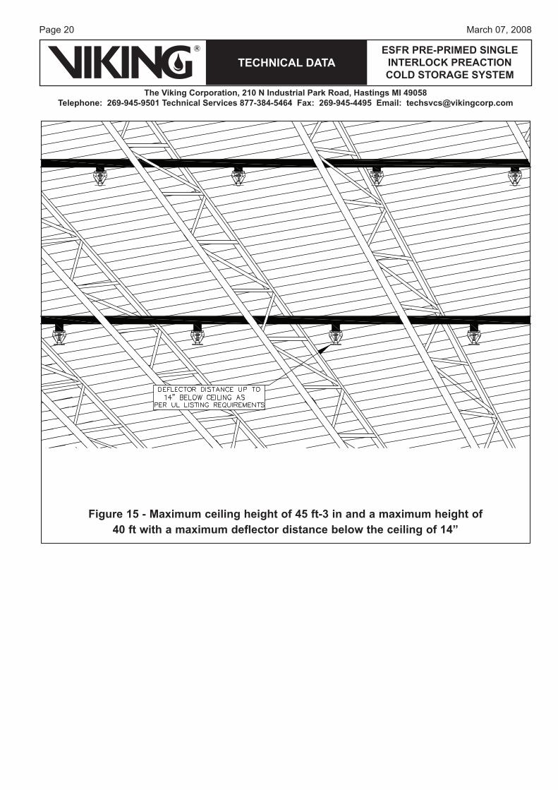
Figure 15 - Maximum ceiling height of 45 ft-3 in and a maximum height of 40 ft with a maximum deflector distance below the ceiling of 14”
Page 21March 07, 2008
TECHNICAL DATAESFR PRE-PRIMED SINGLE
INTERLOCK PREACTION COLD STORAGE SYSTEM
The Viking Corporation, 210 N Industrial Park Road, Hastings MI 49058Telephone: 269-945-9501 Technical Services 877-384-5464 Fax: 269-945-4495 Email: [email protected]
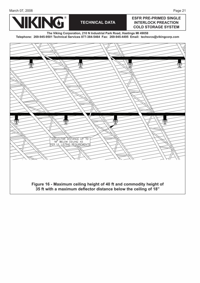
Figure 16 - Maximum ceiling height of 40 ft and commodity height of35 ft with a maximum deflector distance below the ceiling of 18”
Page 22
TECHNICAL DATA
The Viking Corporation, 210 N Industrial Park Road, Hastings MI 49058Telephone: 269-945-9501 Technical Services 877-384-5464 Fax: 269-945-4495 Email: [email protected]
ESFR PRE-PRIMED SINGLE INTERLOCK PREACTION COLD STORAGE SYSTEM
March 07, 2008
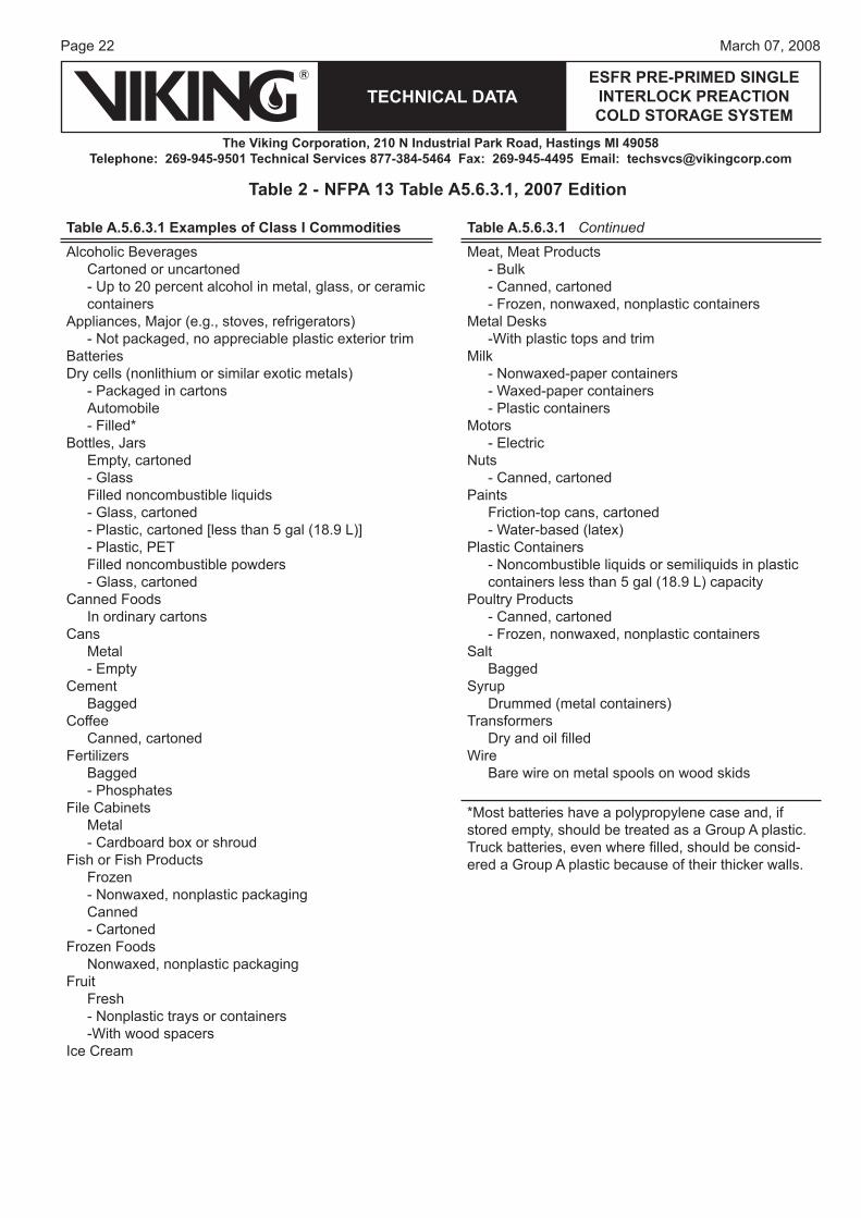
Table A.5.6.3.1 Examples of Class I Commodities Table A.5.6.3.1 Continued
Alcoholic BeveragesCartoned or uncartoned- Up to 20 percent alcohol in metal, glass, or ceramic containers
Appliances, Major (e.g., stoves, refrigerators)- Not packaged, no appreciable plastic exterior trim
BatteriesDry cells (nonlithium or similar exotic metals)
- Packaged in cartonsAutomobile- Filled*
Bottles, JarsEmpty, cartoned- GlassFilled noncombustible liquids- Glass, cartoned- Plastic, cartoned [less than 5 gal (18.9 L)]- Plastic, PETFilled noncombustible powders- Glass, cartoned
Canned FoodsIn ordinary cartons
CansMetal- Empty
CementBagged
CoffeeCanned, cartoned
FertilizersBagged- Phosphates
File CabinetsMetal- Cardboard box or shroud
Fish or Fish ProductsFrozen- Nonwaxed, nonplastic packagingCanned- Cartoned
Frozen FoodsNonwaxed, nonplastic packaging
FruitFresh- Nonplastic trays or containers-With wood spacers
Ice Cream
Meat, Meat Products- Bulk- Canned, cartoned- Frozen, nonwaxed, nonplastic containers
Metal Desks-With plastic tops and trim
Milk- Nonwaxed-paper containers- Waxed-paper containers- Plastic containers
Motors- Electric
Nuts- Canned, cartoned
PaintsFriction-top cans, cartoned- Water-based (latex)
Plastic Containers- Noncombustible liquids or semiliquids in plastic containers less than 5 gal (18.9 L) capacity
Poultry Products- Canned, cartoned- Frozen, nonwaxed, nonplastic containers
SaltBagged
SyrupDrummed (metal containers)
TransformersDry and oil fi lled
WireBare wire on metal spools on wood skids
*Most batteries have a polypropylene case and, if stored empty, should be treated as a Group A plastic. Truck batteries, even where fi lled, should be consid-ered a Group A plastic because of their thicker walls.
Table 2 - NFPA 13 Table A5.6.3.1, 2007 Edition
Page 23March 07, 2008
TECHNICAL DATAESFR PRE-PRIMED SINGLE
INTERLOCK PREACTION COLD STORAGE SYSTEM
The Viking Corporation, 210 N Industrial Park Road, Hastings MI 49058Telephone: 269-945-9501 Technical Services 877-384-5464 Fax: 269-945-4495 Email: [email protected]
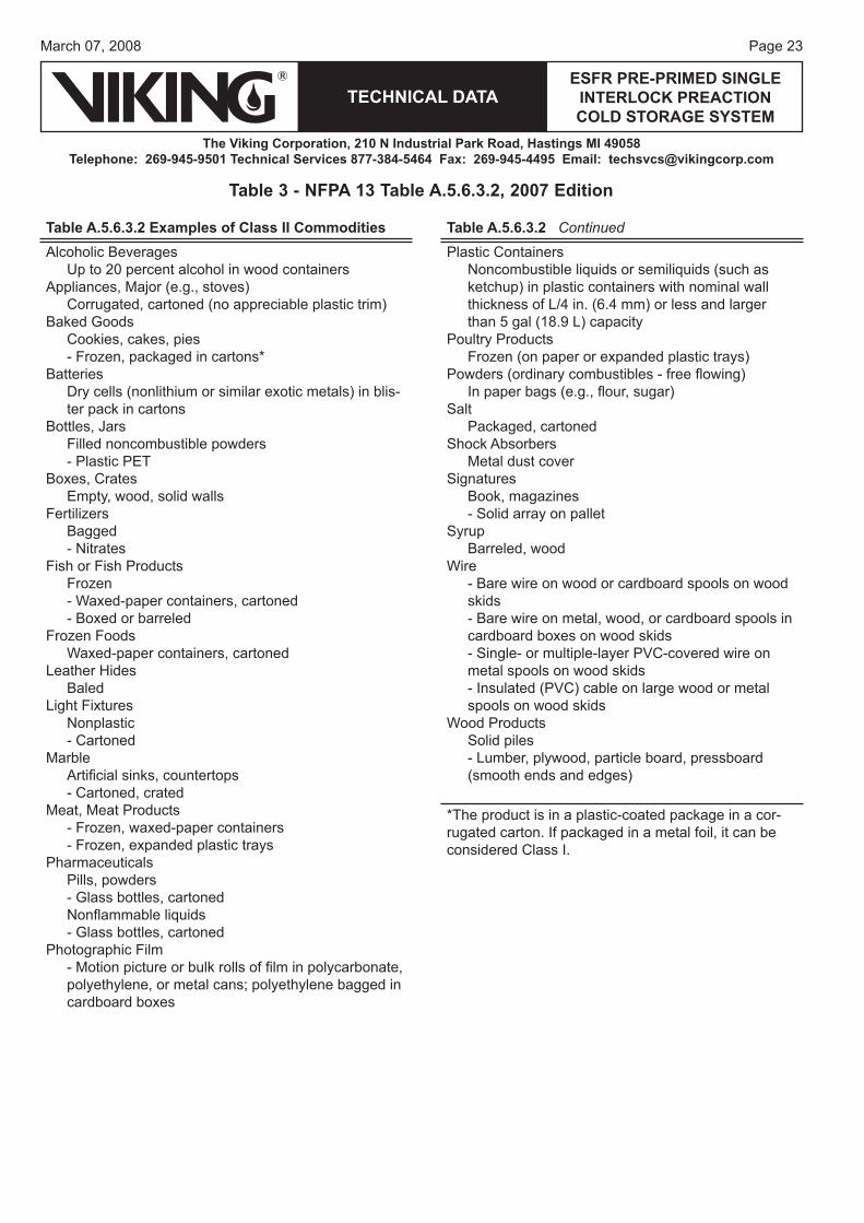
Table A.5.6.3.2 Examples of Class II Commodities Table A.5.6.3.2 Continued
Alcoholic BeveragesUp to 20 percent alcohol in wood containers
Appliances, Major (e.g., stoves)Corrugated, cartoned (no appreciable plastic trim)
Baked GoodsCookies, cakes, pies- Frozen, packaged in cartons*
BatteriesDry cells (nonlithium or similar exotic metals) in blis-ter pack in cartons
Bottles, JarsFilled noncombustible powders- Plastic PET
Boxes, CratesEmpty, wood, solid walls
FertilizersBagged- Nitrates
Fish or Fish ProductsFrozen- Waxed-paper containers, cartoned- Boxed or barreled
Frozen FoodsWaxed-paper containers, cartoned
Leather HidesBaled
Light FixturesNonplastic- Cartoned
MarbleArtifi cial sinks, countertops- Cartoned, crated
Meat, Meat Products- Frozen, waxed-paper containers- Frozen, expanded plastic trays
PharmaceuticalsPills, powders- Glass bottles, cartonedNonfl ammable liquids- Glass bottles, cartoned
Photographic Film- Motion picture or bulk rolls of fi lm in polycarbonate, polyethylene, or metal cans; polyethylene bagged in cardboard boxes
Plastic ContainersNoncombustible liquids or semiliquids (such as ketchup) in plastic containers with nominal wall thickness of L/4 in. (6.4 mm) or less and larger than 5 gal (18.9 L) capacity
Poultry ProductsFrozen (on paper or expanded plastic trays)
Powders (ordinary combustibles - free fl owing)In paper bags (e.g., fl our, sugar)
SaltPackaged, cartoned
Shock AbsorbersMetal dust cover
SignaturesBook, magazines- Solid array on pallet
SyrupBarreled, wood
Wire- Bare wire on wood or cardboard spools on wood skids- Bare wire on metal, wood, or cardboard spools in cardboard boxes on wood skids- Single- or multiple-layer PVC-covered wire on metal spools on wood skids- Insulated (PVC) cable on large wood or metal spools on wood skids
Wood ProductsSolid piles- Lumber, plywood, particle board, pressboard (smooth ends and edges)
*The product is in a plastic-coated package in a cor-rugated carton. If packaged in a metal foil, it can be considered Class I.
Table 3 - NFPA 13 Table A.5.6.3.2, 2007 Edition
Page 24
TECHNICAL DATA
The Viking Corporation, 210 N Industrial Park Road, Hastings MI 49058Telephone: 269-945-9501 Technical Services 877-384-5464 Fax: 269-945-4495 Email: [email protected]
ESFR PRE-PRIMED SINGLE INTERLOCK PREACTION COLD STORAGE SYSTEM
March 07, 2008
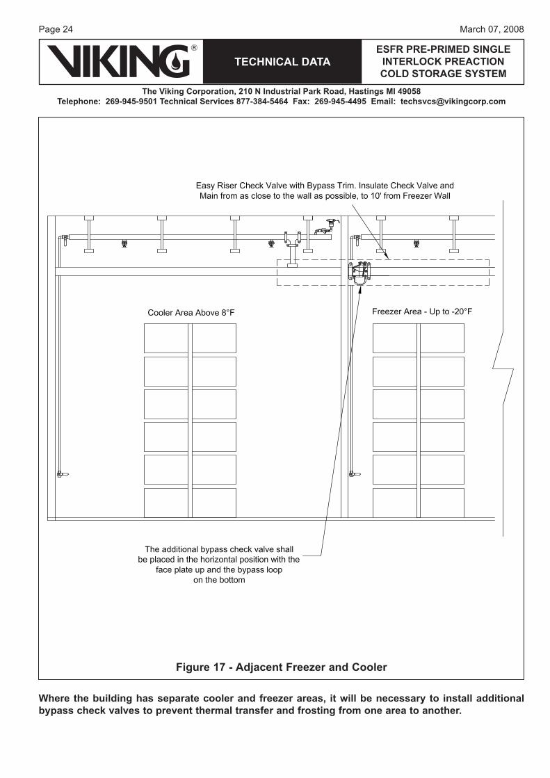
Where the building has separate cooler and freezer areas, it will be necessary to install additional bypass check valves to prevent thermal transfer and frosting from one area to another.
Figure 17 - Adjacent Freezer and Cooler
Page 25March 07, 2008
TECHNICAL DATAESFR PRE-PRIMED SINGLE
INTERLOCK PREACTION COLD STORAGE SYSTEM
The Viking Corporation, 210 N Industrial Park Road, Hastings MI 49058Telephone: 269-945-9501 Technical Services 877-384-5464 Fax: 269-945-4495 Email: [email protected]
Page 26
TECHNICAL DATA
The Viking Corporation, 210 N Industrial Park Road, Hastings MI 49058Telephone: 269-945-9501 Technical Services 877-384-5464 Fax: 269-945-4495 Email: [email protected]
ESFR PRE-PRIMED SINGLE INTERLOCK PREACTION COLD STORAGE SYSTEM
March 07, 2008
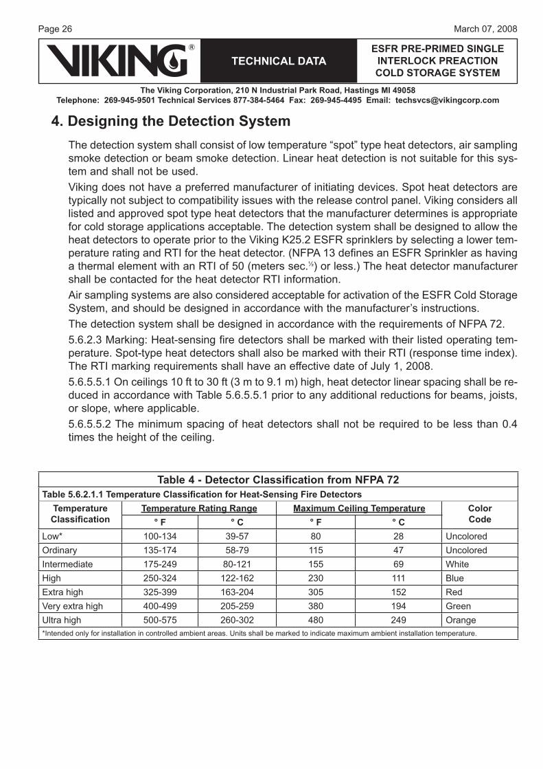
4. Designing the Detection SystemThe detection system shall consist of low temperature “spot” type heat detectors, air sampling smoke detection or beam smoke detection. Linear heat detection is not suitable for this sys-tem and shall not be used.Viking does not have a preferred manufacturer of initiating devices. Spot heat detectors are typically not subject to compatibility issues with the release control panel. Viking considers all listed and approved spot type heat detectors that the manufacturer determines is appropriate for cold storage applications acceptable. The detection system shall be designed to allow the heat detectors to operate prior to the Viking K25.2 ESFR sprinklers by selecting a lower tem-perature rating and RTI for the heat detector. (NFPA 13 defines an ESFR Sprinkler as having a thermal element with an RTI of 50 (meters sec.½) or less.) The heat detector manufacturer shall be contacted for the heat detector RTI information.Air sampling systems are also considered acceptable for activation of the ESFR Cold Storage System, and should be designed in accordance with the manufacturer’s instructions.The detection system shall be designed in accordance with the requirements of NFPA 72.5.6.2.3 Marking: Heat-sensing fire detectors shall be marked with their listed operating tem-perature. Spot-type heat detectors shall also be marked with their RTI (response time index). The RTI marking requirements shall have an effective date of July 1, 2008.5.6.5.5.1 On ceilings 10 ft to 30 ft (3 m to 9.1 m) high, heat detector linear spacing shall be re-duced in accordance with Table 5.6.5.5.1 prior to any additional reductions for beams, joists, or slope, where applicable.5.6.5.5.2 The minimum spacing of heat detectors shall not be required to be less than 0.4 times the height of the ceiling.
Table 4 - Detector Classification from NFPA 72Table 5.6.2.1.1 Temperature Classifi cation for Heat-Sensing Fire Detectors
Temperature Classifi cation
Temperature Rating Range Maximum Ceiling Temperature ColorCode° F ° C ° F ° C
Low* 100-134 39-57 80 28 UncoloredOrdinary 135-174 58-79 115 47 UncoloredIntermediate 175-249 80-121 155 69 WhiteHigh 250-324 122-162 230 111 BlueExtra high 325-399 163-204 305 152 RedVery extra high 400-499 205-259 380 194 GreenUltra high 500-575 260-302 480 249 Orange*Intended only for installation in controlled ambient areas. Units shall be marked to indicate maximum ambient installation temperature.
Page 27March 07, 2008
TECHNICAL DATAESFR PRE-PRIMED SINGLE
INTERLOCK PREACTION COLD STORAGE SYSTEM
The Viking Corporation, 210 N Industrial Park Road, Hastings MI 49058Telephone: 269-945-9501 Technical Services 877-384-5464 Fax: 269-945-4495 Email: [email protected]
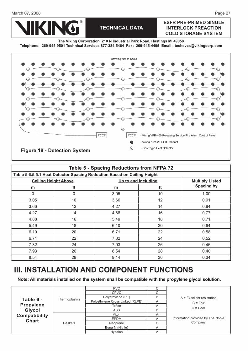
Figure 18 - Detection System
Table 5 - Spacing Reductions from NFPA 72Table 5.6.5.5.1 Heat Detector Spacing Reduction Based on Ceiling Height
Ceiling Height Above Up to and Including Multiply Listed Spacing bym ft m ft
0 0 3.05 10 1.003.05 10 3.66 12 0.913.66 12 4.27 14 0.844.27 14 4.88 16 0.774.88 16 5.49 18 0.715.49 18 6.10 20 0.646.10 20 6.71 22 0.586.71 22 7.32 24 0.527.32 24 7.93 26 0.467.93 26 8.54 28 0.408.54 28 9.14 30 0.34
III. INSTALLATION AND COMPONENT FUNCTIONSNote: All materials installed on the system shall be compatible with the propylene glycol solution.
Table 6 - Propylene
Glycol Compatibility
Chart
Thermoplastics
PVC C
A = Excellent resistanceB = FairC = Poor
Information provided by The Noble Company
CPVC CPolyethylene (PE) B
Polyethylene Cross Linked (XLPE) ATeflon AABS B
Gaskets
Viton AEPDM A
Neoprene CBuna N (Nitrile) A
Hypalon A
Page 28
TECHNICAL DATA
The Viking Corporation, 210 N Industrial Park Road, Hastings MI 49058Telephone: 269-945-9501 Technical Services 877-384-5464 Fax: 269-945-4495 Email: [email protected]
ESFR PRE-PRIMED SINGLE INTERLOCK PREACTION COLD STORAGE SYSTEM
March 07, 2008
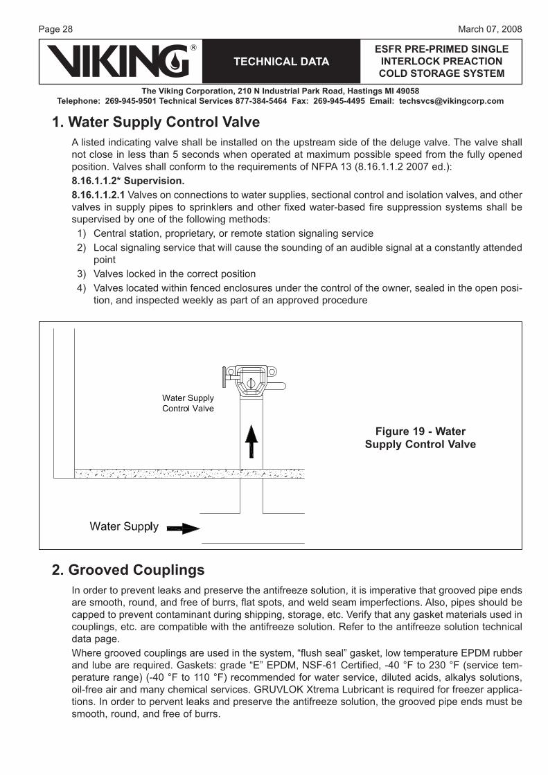
1. Water Supply Control ValveA listed indicating valve shall be installed on the upstream side of the deluge valve. The valve shall not close in less than 5 seconds when operated at maximum possible speed from the fully opened position. Valves shall conform to the requirements of NFPA 13 (8.16.1.1.2 2007 ed.):8.16.1.1.2* Supervision.8.16.1.1.2.1 Valves on connections to water supplies, sectional control and isolation valves, and other valves in supply pipes to sprinklers and other fixed water-based fire suppression systems shall be supervised by one of the following methods:
Central station, proprietary, or remote station signaling serviceLocal signaling service that will cause the sounding of an audible signal at a constantly attended pointValves locked in the correct positionValves located within fenced enclosures under the control of the owner, sealed in the open posi-tion, and inspected weekly as part of an approved procedure
1)2)
3)4)
Figure 19 - Water Supply Control Valve
2. Grooved CouplingsIn order to prevent leaks and preserve the antifreeze solution, it is imperative that grooved pipe ends are smooth, round, and free of burrs, flat spots, and weld seam imperfections. Also, pipes should be capped to prevent contaminant during shipping, storage, etc. Verify that any gasket materials used in couplings, etc. are compatible with the antifreeze solution. Refer to the antifreeze solution technical data page.Where grooved couplings are used in the system, “flush seal” gasket, low temperature EPDM rubber and lube are required. Gaskets: grade “E” EPDM, NSF-61 Certified, -40 °F to 230 °F (service tem-perature range) (-40 °F to 110 °F) recommended for water service, diluted acids, alkalys solutions, oil-free air and many chemical services. GRUVLOK Xtrema Lubricant is required for freezer applica-tions. In order to pervent leaks and preserve the antifreeze solution, the grooved pipe ends must be smooth, round, and free of burrs.
Page 29March 07, 2008
TECHNICAL DATAESFR PRE-PRIMED SINGLE
INTERLOCK PREACTION COLD STORAGE SYSTEM
The Viking Corporation, 210 N Industrial Park Road, Hastings MI 49058Telephone: 269-945-9501 Technical Services 877-384-5464 Fax: 269-945-4495 Email: [email protected]
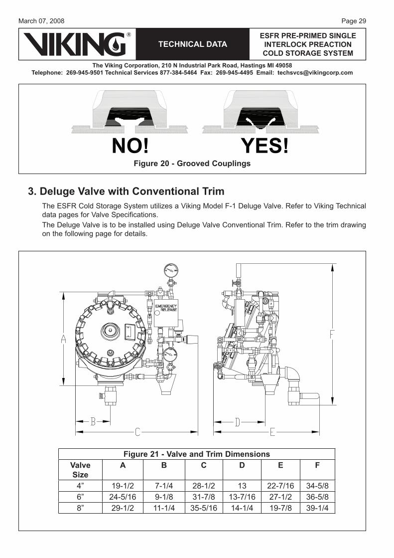
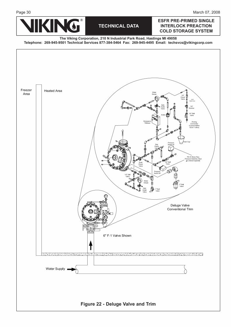
3. Deluge Valve with Conventional TrimThe ESFR Cold Storage System utilizes a Viking Model F-1 Deluge Valve. Refer to Viking Technical data pages for Valve Specifications.The Deluge Valve is to be installed using Deluge Valve Conventional Trim. Refer to the trim drawing on the following page for details.
Figure 21 - Valve and Trim DimensionsValve Size
A B C D E F
4” 19-1/2 7-1/4 28-1/2 13 22-7/16 34-5/86” 24-5/16 9-1/8 31-7/8 13-7/16 27-1/2 36-5/88” 29-1/2 11-1/4 35-5/16 14-1/4 19-7/8 39-1/4
Figure 20 - Grooved Couplings
Page 30
TECHNICAL DATA
The Viking Corporation, 210 N Industrial Park Road, Hastings MI 49058Telephone: 269-945-9501 Technical Services 877-384-5464 Fax: 269-945-4495 Email: [email protected]
ESFR PRE-PRIMED SINGLE INTERLOCK PREACTION COLD STORAGE SYSTEM
March 07, 2008
Figure 22 - Deluge Valve and Trim
Page 31March 07, 2008
TECHNICAL DATAESFR PRE-PRIMED SINGLE
INTERLOCK PREACTION COLD STORAGE SYSTEM
The Viking Corporation, 210 N Industrial Park Road, Hastings MI 49058Telephone: 269-945-9501 Technical Services 877-384-5464 Fax: 269-945-4495 Email: [email protected]
NOTES: An alarm test connection is provided on the deluge valve trim. When testing the alarm, the downstream isolation valve (illustrated in Figure 30) and antifreeze isolation valve (illustrated in Figure 33) must be shut before opening the test valve.
This is a precaution in case the deluge valve would inadvertently operate due to problems in the trim components and cause water to enter the system causing possible contamination of antifreeze. After testing of the alarm, restore the control valves to their normal operating position and open the antifreeze supply valve.
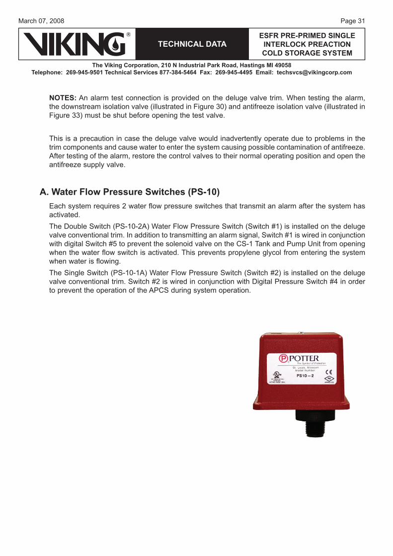
A. Water Flow Pressure Switches (PS-10)Each system requires 2 water flow pressure switches that transmit an alarm after the system has activated. The Double Switch (PS-10-2A) Water Flow Pressure Switch (Switch #1) is installed on the deluge valve conventional trim. In addition to transmitting an alarm signal, Switch #1 is wired in conjunction with digital Switch #5 to prevent the solenoid valve on the CS-1 Tank and Pump Unit from opening when the water flow switch is activated. This prevents propylene glycol from entering the system when water is flowing.The Single Switch (PS-10-1A) Water Flow Pressure Switch (Switch #2) is installed on the deluge valve conventional trim. Switch #2 is wired in conjunction with Digital Pressure Switch #4 in order to prevent the operation of the APCS during system operation.
Page 32
TECHNICAL DATA
The Viking Corporation, 210 N Industrial Park Road, Hastings MI 49058Telephone: 269-945-9501 Technical Services 877-384-5464 Fax: 269-945-4495 Email: [email protected]
ESFR PRE-PRIMED SINGLE INTERLOCK PREACTION COLD STORAGE SYSTEM
March 07, 2008
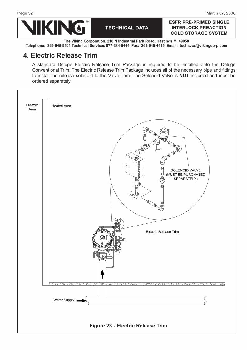
4. Electric Release TrimA standard Deluge Electric Release Trim Package is required to be installed onto the Deluge Conventional Trim. The Electric Release Trim Package includes all of the necessary pipe and fittings to install the release solenoid to the Valve Trim. The Solenoid Valve is NOT included and must be ordered separately.
Figure 23 - Electric Release Trim
Page 33March 07, 2008
TECHNICAL DATAESFR PRE-PRIMED SINGLE
INTERLOCK PREACTION COLD STORAGE SYSTEM
The Viking Corporation, 210 N Industrial Park Road, Hastings MI 49058Telephone: 269-945-9501 Technical Services 877-384-5464 Fax: 269-945-4495 Email: [email protected]
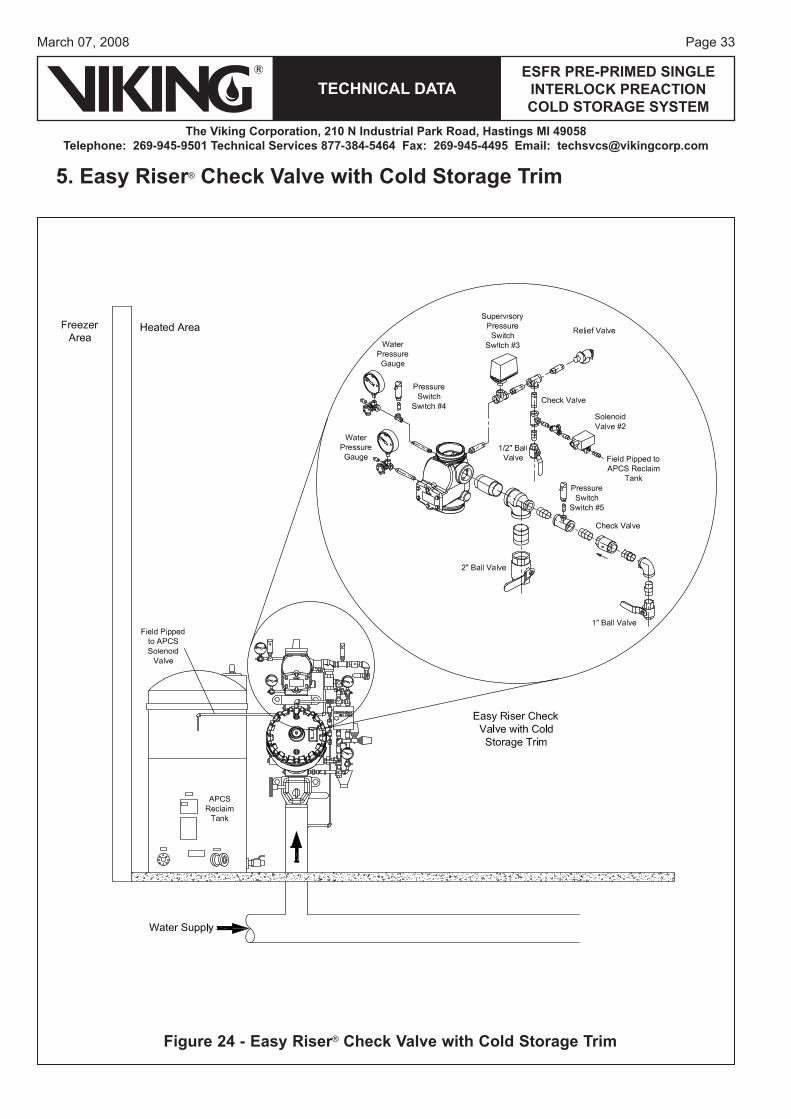
5. Easy Riser® Check Valve with Cold Storage Trim
Figure 24 - Easy Riser® Check Valve with Cold Storage Trim

Page 34
TECHNICAL DATA
The Viking Corporation, 210 N Industrial Park Road, Hastings MI 49058Telephone: 269-945-9501 Technical Services 877-384-5464 Fax: 269-945-4495 Email: [email protected]
ESFR PRE-PRIMED SINGLE INTERLOCK PREACTION COLD STORAGE SYSTEM
March 07, 2008
A. Cold Storage Trim with Automatic Pressure Control SystemIn cold storage areas where temperatures can fluctuate, over-pressurization of the system can occur. The Automatic Pressure Control System (APCS) is used to prevent this from occurring. The pressure relief valve (PRV) operates when the set point of 205 PSI (14.1 Bar) is reached. Normal operation of the PRV includes operation at 90-105% of the set point and closing at 80% of the set point. The Automatic Pressure Control System (APCS) is designed to maintain a safe operat-ing pressure below the set point of the PRV and above the maximum residual or static pressure of water supply system or maximum set pressure of the system pressure switch. The Automatic Pressure Control Trim is included with the Easy Riser® Cold Storage Trim and installed on the pri-mary Easy Riser® Check Valve.The APCS includes an electronic digital pressure switch that includes a normally open SPST switch that is set to close at a pressure below the PRV set point and open above the static water supply or shut-off pressure of the riser system. A waterflow switch is to be installed on the non-interruptible alarm port of the conventional trim on the deluge valve. A normally closed solenoid valve is to be installed on the cold storage trim at the ¼” connection provided. A 115-220 VAC, (50 or 60 Hz) GFI protected electrical power supply is to be provided directly to the switch. During normal operating condition, the propylene glycol within the system piping network is pres-surized to 50 PSI (3.45 Bar). The APCS uses a digital pressure switch (Switch #4) in conjunction with a 120 VAC solenoid (Switch #2) to relieve pressure from the system when the pressure ex-ceeds 85 PSI (5.86 Bar). The digital pressure switch (#4) comes factory set to operate and energize the solenoid (#2) at 75 PSI (5.17 Bar). The digital pressure switch will change state and remove power from the solenoid (#2) at 85 PSI (5.86 Bar).The digital pressure switch (#4) and solenoid (#2) are wired and powered from a dedicated 115-220 VAC (50 or 60 Hz) power supply and routed through a water flow pressure switch (#2) as shown in Figure 39. These devices operate independently and are not connected to either the release control panel or the CS-1 tank and pump unit. The water flow pressure switch prevents the APCS from operating under normal water flow conditions.The pressure switch on the deluge valve will make the APCS inoperable when the detection system causes the deluge valve to open. This prevents water flow from the APCS.
1. Supervisory Pressure Switch (PS-40)The Automatic Pressure Control System includes aPS-40 Supervisory Pressure Switch that is installedon the primary Easy Riser® Check Valve and wired tothe appropriate supervisory circuit on the Viking VFR-400 to annunciate a supervisory signal upon a lowpressure condition with the propylene glycol. It isrecommended to set the switch to activate at 30 PSI(2.07 Bar).
Page 35March 07, 2008
TECHNICAL DATAESFR PRE-PRIMED SINGLE
INTERLOCK PREACTION COLD STORAGE SYSTEM
The Viking Corporation, 210 N Industrial Park Road, Hastings MI 49058Telephone: 269-945-9501 Technical Services 877-384-5464 Fax: 269-945-4495 Email: [email protected]
Pressure Connection: ¼” female NPTElectrical Connection: ½” UNF-Connector, angled designMaximum System Pressure: 175 PSI (12 Bar)Voltage: 85-265 AC (45-65 HZ)Current Rating [mA]:2.5A @ 68 °F (20 °C)1.5A @ 113 °F (45 °C)1A @ 140 °F (60 °C)0.25A @ 158 °F (70 °C)Current Consumption: < 10 mAProtection: IP65, Protection Class: IIOperating Temperature: -13 °F (-25 °C) to 176 °F (80 °C)Not for use in hazardous locationsCable Part Number 13231 is 13 ft (4 m) longMaterial Standards:Stainless Steel (303S22), ceramics; FPM (Viton)Housing: EPDM/X (Santoprene), FPM (Viton), PA, Pocan, PC (Macrolon), Stainless Steel (304S15)Body: TPU (urethane)Nut: Brass, nickel platedWrench Flats: 30 mm
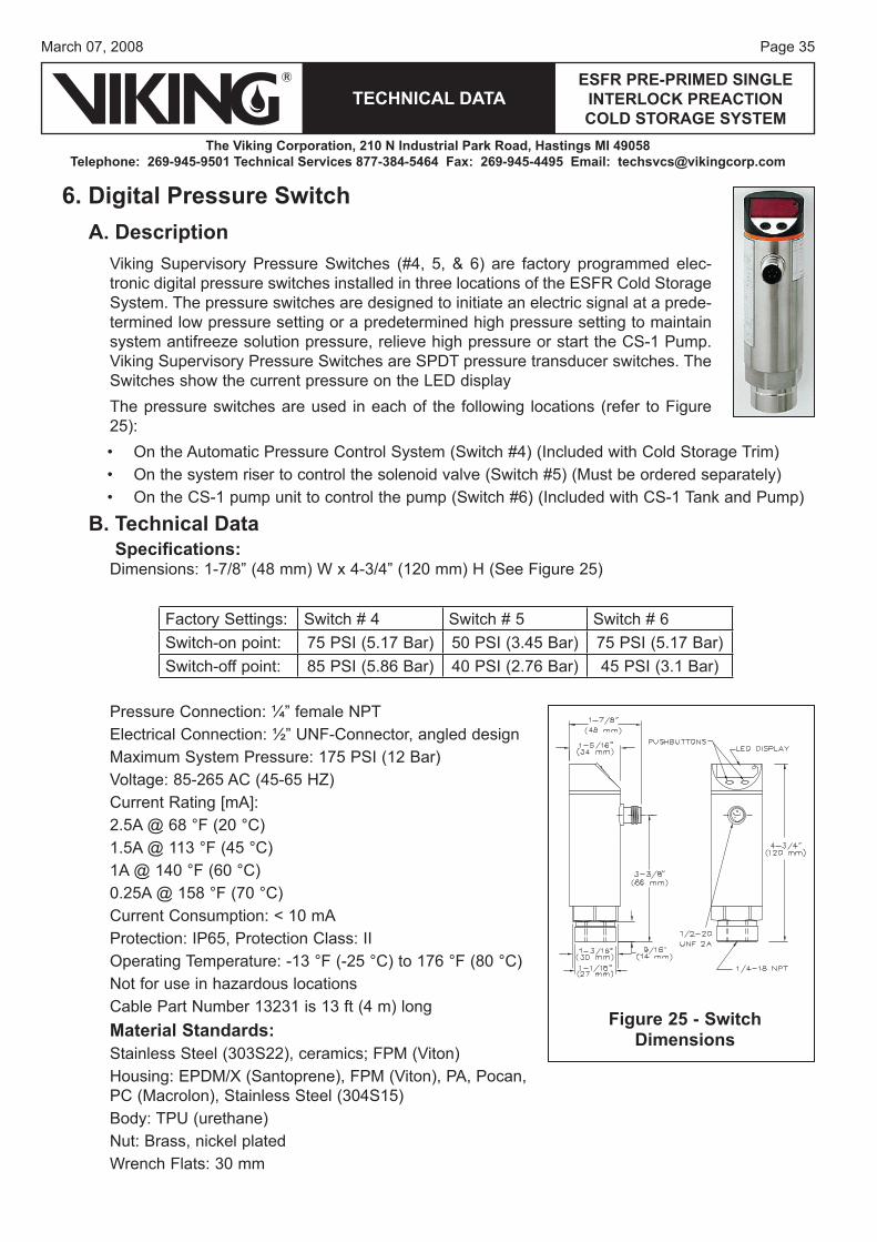
6. Digital Pressure Switch A. Description
Viking Supervisory Pressure Switches (#4, 5, & 6) are factory programmed elec-tronic digital pressure switches installed in three locations of the ESFR Cold Storage System. The pressure switches are designed to initiate an electric signal at a prede-termined low pressure setting or a predetermined high pressure setting to maintain system antifreeze solution pressure, relieve high pressure or start the CS-1 Pump. Viking Supervisory Pressure Switches are SPDT pressure transducer switches. The Switches show the current pressure on the LED displayThe pressure switches are used in each of the following locations (refer to Figure 25):
On the Automatic Pressure Control System (Switch #4) (Included with Cold Storage Trim)On the system riser to control the solenoid valve (Switch #5) (Must be ordered separately)On the CS-1 pump unit to control the pump (Switch #6) (Included with CS-1 Tank and Pump)
B. Technical DataSpecifi cations:
Dimensions: 1-7/8” (48 mm) W x 4-3/4” (120 mm) H (See Figure 25)
•••
Factory Settings: Switch # 4 Switch # 5 Switch # 6Switch-on point: 75 PSI (5.17 Bar) 50 PSI (3.45 Bar) 75 PSI (5.17 Bar)Switch-off point: 85 PSI (5.86 Bar) 40 PSI (2.76 Bar) 45 PSI (3.1 Bar)
Figure 25 - Switch Dimensions
Page 36
TECHNICAL DATA
The Viking Corporation, 210 N Industrial Park Road, Hastings MI 49058Telephone: 269-945-9501 Technical Services 877-384-5464 Fax: 269-945-4495 Email: [email protected]
ESFR PRE-PRIMED SINGLE INTERLOCK PREACTION COLD STORAGE SYSTEM
March 07, 2008
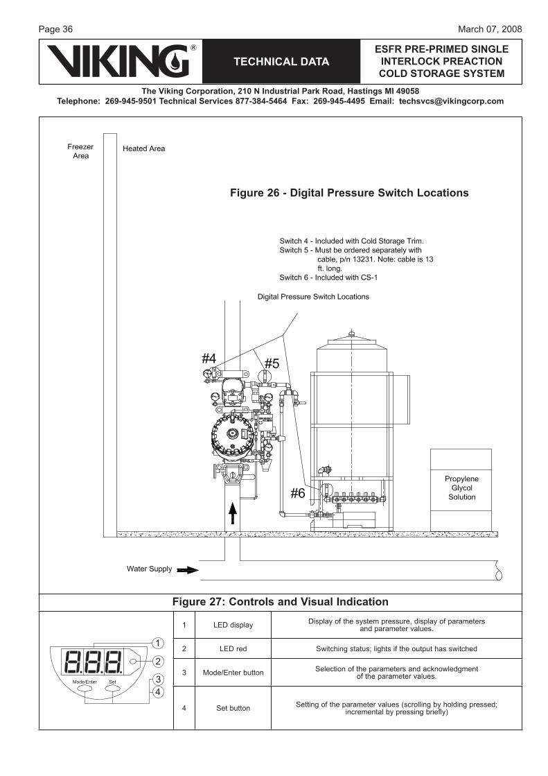
Figure 27: Controls and Visual Indication
Mode/Enter Set
1
2
34
1 LED display Display of the system pressure, display of parametersand parameter values.
2 LED red Switching status; lights if the output has switched
3 Mode/Enter button Selection of the parameters and acknowledgmentof the parameter values.
4 Set button Setting of the parameter values (scrolling by holding pressed;incremental by pressing briefly)
Figure 26 - Digital Pressure Switch Locations
Page 37March 07, 2008
TECHNICAL DATAESFR PRE-PRIMED SINGLE
INTERLOCK PREACTION COLD STORAGE SYSTEM
The Viking Corporation, 210 N Industrial Park Road, Hastings MI 49058Telephone: 269-945-9501 Technical Services 877-384-5464 Fax: 269-945-4495 Email: [email protected]
Ordering Information:Part Numbers: Switch - 13057 (Must be ordered for Switch #5) Cable - 13231
C. Operating ModesRun Mode (normal operating mode): When the supply voltage has been applied, the unit is in the Run mode. It monitors and switches the output according to the set parameters. The display shows the current system pressure. The red LED indicates the switching state of the output. Display Mode (indication of parameters and the set parameter values): When the “Mode/Enter” button is pressed for a short time, the unit passes to the Display mode. Internally it remains in the operating mode. The parameter names are scrolled with each pressing of the “Mode/Enter” button. When the “Set” button is pressed for a short time, the corresponding pa-rameter value is displayed for approximately 15 seconds. Then the unit returns to the Run mode.Locking / UnlockingThe units are electronically locked to prevent unwanted adjustment of the set parameters; Press (in Run mode) both setting buttons for 10 seconds. As soon as the indication goes out, the unit is locked or unlocked. Units are delivered from the factory in the locked state. With the unit in the locked state, “Loc” is indicated briefly when you try to change parameter values.
D. Installation Before installing or removing a pressure switch, make sure that no pressure is applied to the system.
1. When installing the switch, apply Teflon tape sealant to the male threads only.2. Install the Supervisory Pressure Switch in the ¼” NPT connection. Use a wrench applied to
the wrench flats to tighten the unit. Do not over-tighten. Mount the switch in the upright posi-tion (threaded connection down).
3. To wire the unit proceed as follows: a. De-energize electrical circuits involved.b. Connect cable (Viking Part No. 13213) to the ½” conduit opening provided.c. Connect electrical circuitry for the signalling device and auxiliary equipment being controlled
by the switch. Refer to the wiring diagrams. Wire all devices to national and local codes and requirements of the Authority Having Jurisdiction.
4. Energize the circuits.
1. Electrical Connection:The unit must only be connected by a certified electrician. National and international regulations for the installation of electrical equipment must be observed. Caution: For the output circuit, the same protective measures as for the supply circuit must be taken. A 115 VAC (60 HZ) or 220 VAC (50 HZ) electrical power supply is to be provided directly to the switch when used for APCS. Alternately, connect to the CS-1 panel. When used for system control, direct connection to the switch must be made with Viking Cable Part No. 13231.
Page 38
TECHNICAL DATA
The Viking Corporation, 210 N Industrial Park Road, Hastings MI 49058Telephone: 269-945-9501 Technical Services 877-384-5464 Fax: 269-945-4495 Email: [email protected]
ESFR PRE-PRIMED SINGLE INTERLOCK PREACTION COLD STORAGE SYSTEM
March 07, 2008
E. Inspections, Tests and MaintenanceOperate and test the Supervisory Pressure Switch after installation, prior to start-up, and periodically as required in the Viking technical data pages, the installation standards, and/or the Authority Having Jurisdiction. Quarterly testing of Pressure Supervisory Switches is recommended. Refer to ESFR Cold Storage System data page 45a-j for testing requirements and procedures. NOTICE: The owner is responsible for maintaining the fire-protection system and devices in proper operating condition. For minimum maintenance and inspection requirements, refer to NFPA 25 and Viking’s ESFR Cold Storage System Manual.
1. Periodic Test and MaintenanceCaution: For auxiliary equipment controlled by operation of the switch, take the steps neces-sary to prevent unwanted operation or shutdown of those devices when testing.Warning: Any system maintenance that involves placing a control valve or detection system out of service may eliminate the fire-protection capabilities of that system. Prior to proceeding, notify all Authorities Having Jurisdiction. Consideration should be given to employment of a fire patrol in the affected areas.1. Refer to Viking technical data page 45a-j and the ESFR Cold Storage System Manual for
testing and maintenance instructions.2. If test is satisfactory, reset all necessary equipment, and place the system in service.
2. Supervisory Switch AdjustmentConsult the ESFR Cold Storage System technical data pages for recommended pressure set-tings for each location where the Supervisory Pressure Switch is installed on the system. The switches are factory set. If adjustment is necessary, proceed according to the instructions given below.1. If the unit is in the locked state, “Loc” is indicated briefly when you try to change parameter
values, press (in Run mode) both setting buttons for 10 seconds. As soon as the indication goes out, the unit is unlocked.
2. Verify pressure settings of the switch.3. Test for proper operation of the device.4. The unit can be electronically locked to prevent unwanted adjustment of the set parameters;
Press (in Run mode) both setting buttons for 10 seconds. As soon as the indication goes out, the unit is locked. With the unit in the locked state, “Loc” is indicated briefly when you try to change parameter values.
5. Reset all necessary equipment and place the system in service. Refer to the ESFR Cold Storage System technical data pages.
Page 39March 07, 2008
TECHNICAL DATAESFR PRE-PRIMED SINGLE
INTERLOCK PREACTION COLD STORAGE SYSTEM
The Viking Corporation, 210 N Industrial Park Road, Hastings MI 49058Telephone: 269-945-9501 Technical Services 877-384-5464 Fax: 269-945-4495 Email: [email protected]
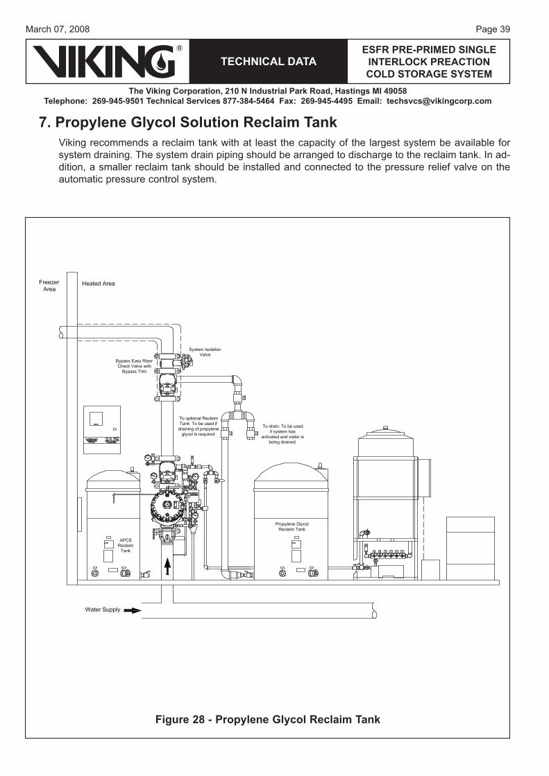
7. Propylene Glycol Solution Reclaim TankViking recommends a reclaim tank with at least the capacity of the largest system be available for system draining. The system drain piping should be arranged to discharge to the reclaim tank. In ad-dition, a smaller reclaim tank should be installed and connected to the pressure relief valve on the automatic pressure control system.
Figure 28 - Propylene Glycol Reclaim Tank
Page 40
TECHNICAL DATA
The Viking Corporation, 210 N Industrial Park Road, Hastings MI 49058Telephone: 269-945-9501 Technical Services 877-384-5464 Fax: 269-945-4495 Email: [email protected]
ESFR PRE-PRIMED SINGLE INTERLOCK PREACTION COLD STORAGE SYSTEM
March 07, 2008
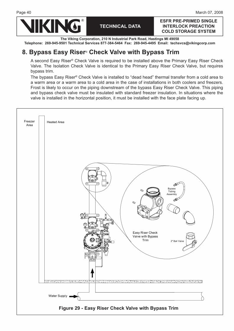
8. Bypass Easy Riser® Check Valve with Bypass TrimA second Easy Riser® Check Valve is required to be installed above the Primary Easy Riser Check Valve. The Isolation Check Valve is identical to the Primary Easy Riser Check Valve, but requires bypass trim. The bypass Easy Riser® Check Valve is installed to “dead head” thermal transfer from a cold area to a warm area or a warm area to a cold area in the case of installations in both coolers and freezers. Frost is likely to occur on the piping downstream of the bypass Easy Riser Check Valve. This piping and bypass check valve must be insulated with standard freezer insulation. In situations where the valve is installed in the horizontal position, it must be installed with the face plate facing up.
Figure 29 - Easy Riser Check Valve with Bypass Trim
Page 41March 07, 2008
TECHNICAL DATAESFR PRE-PRIMED SINGLE
INTERLOCK PREACTION COLD STORAGE SYSTEM
The Viking Corporation, 210 N Industrial Park Road, Hastings MI 49058Telephone: 269-945-9501 Technical Services 877-384-5464 Fax: 269-945-4495 Email: [email protected]
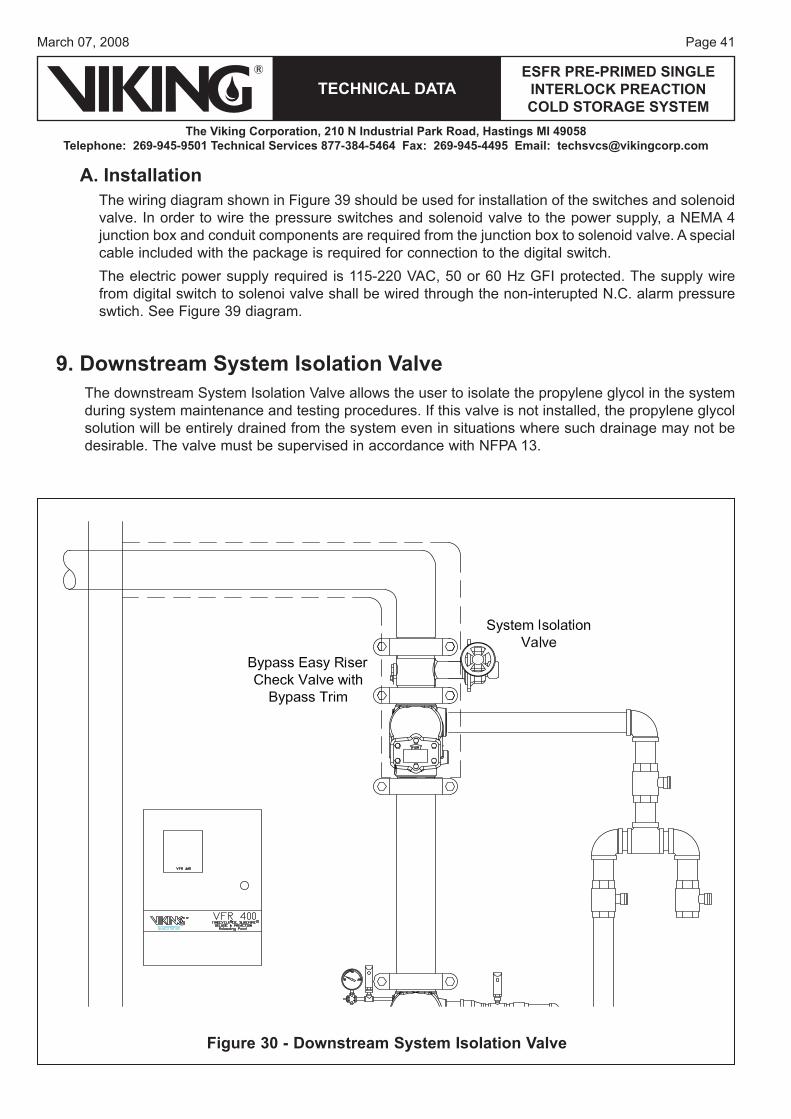
A. InstallationThe wiring diagram shown in Figure 39 should be used for installation of the switches and solenoid valve. In order to wire the pressure switches and solenoid valve to the power supply, a NEMA 4 junction box and conduit components are required from the junction box to solenoid valve. A special cable included with the package is required for connection to the digital switch.The electric power supply required is 115-220 VAC, 50 or 60 Hz GFI protected. The supply wire from digital switch to solenoi valve shall be wired through the non-interupted N.C. alarm pressure swtich. See Figure 39 diagram.
9. Downstream System Isolation ValveThe downstream System Isolation Valve allows the user to isolate the propylene glycol in the system during system maintenance and testing procedures. If this valve is not installed, the propylene glycol solution will be entirely drained from the system even in situations where such drainage may not be desirable. The valve must be supervised in accordance with NFPA 13.
Figure 30 - Downstream System Isolation Valve
Page 42
TECHNICAL DATA
The Viking Corporation, 210 N Industrial Park Road, Hastings MI 49058Telephone: 269-945-9501 Technical Services 877-384-5464 Fax: 269-945-4495 Email: [email protected]
ESFR PRE-PRIMED SINGLE INTERLOCK PREACTION COLD STORAGE SYSTEM
March 07, 2008
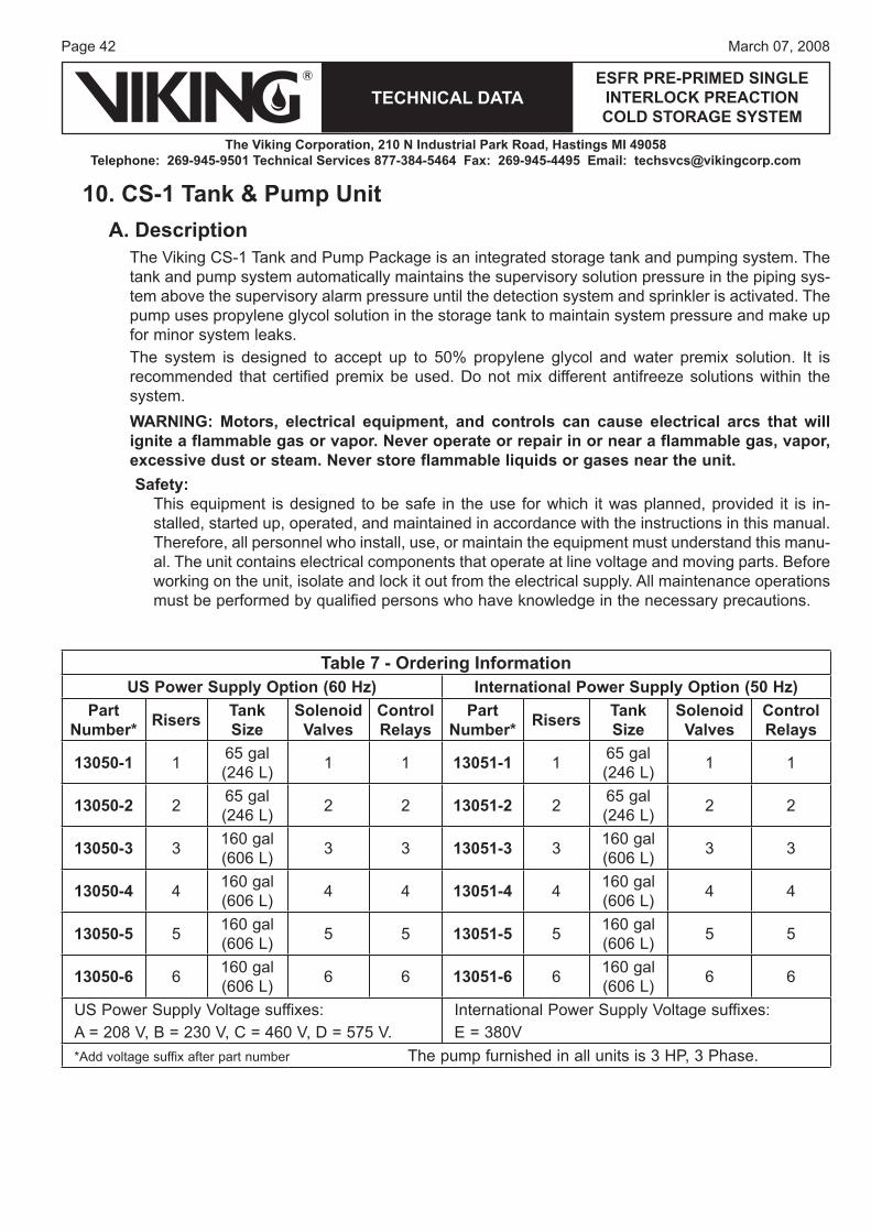
10. CS-1 Tank & Pump UnitA. Description
The Viking CS-1 Tank and Pump Package is an integrated storage tank and pumping system. The tank and pump system automatically maintains the supervisory solution pressure in the piping sys-tem above the supervisory alarm pressure until the detection system and sprinkler is activated. The pump uses propylene glycol solution in the storage tank to maintain system pressure and make up for minor system leaks.The system is designed to accept up to 50% propylene glycol and water premix solution. It is recommended that certified premix be used. Do not mix different antifreeze solutions within the system.WARNING: Motors, electrical equipment, and controls can cause electrical arcs that will ignite a flammable gas or vapor. Never operate or repair in or near a flammable gas, vapor, excessive dust or steam. Never store flammable liquids or gases near the unit.Safety:
This equipment is designed to be safe in the use for which it was planned, provided it is in-stalled, started up, operated, and maintained in accordance with the instructions in this manual. Therefore, all personnel who install, use, or maintain the equipment must understand this manu-al. The unit contains electrical components that operate at line voltage and moving parts. Before working on the unit, isolate and lock it out from the electrical supply. All maintenance operations must be performed by qualified persons who have knowledge in the necessary precautions.
Table 7 - Ordering InformationUS Power Supply Option (60 Hz) International Power Supply Option (50 Hz)
Part Number* Risers Tank
SizeSolenoid Valves
Control Relays
Part Number* Risers Tank
SizeSolenoid Valves
Control Relays
13050-1 1 65 gal (246 L) 1 1 13051-1 1 65 gal
(246 L) 1 1
13050-2 2 65 gal (246 L) 2 2 13051-2 2 65 gal
(246 L) 2 2
13050-3 3 160 gal (606 L) 3 3 13051-3 3 160 gal
(606 L) 3 3
13050-4 4 160 gal (606 L) 4 4 13051-4 4 160 gal
(606 L) 4 4
13050-5 5 160 gal (606 L) 5 5 13051-5 5 160 gal
(606 L) 5 5
13050-6 6 160 gal (606 L) 6 6 13051-6 6 160 gal
(606 L) 6 6
US Power Supply Voltage suffixes:A = 208 V, B = 230 V, C = 460 V, D = 575 V.
International Power Supply Voltage suffixes:E = 380V
*Add voltage suffix after part number The pump furnished in all units is 3 HP, 3 Phase.
Page 43March 07, 2008
TECHNICAL DATAESFR PRE-PRIMED SINGLE
INTERLOCK PREACTION COLD STORAGE SYSTEM
The Viking Corporation, 210 N Industrial Park Road, Hastings MI 49058Telephone: 269-945-9501 Technical Services 877-384-5464 Fax: 269-945-4495 Email: [email protected]
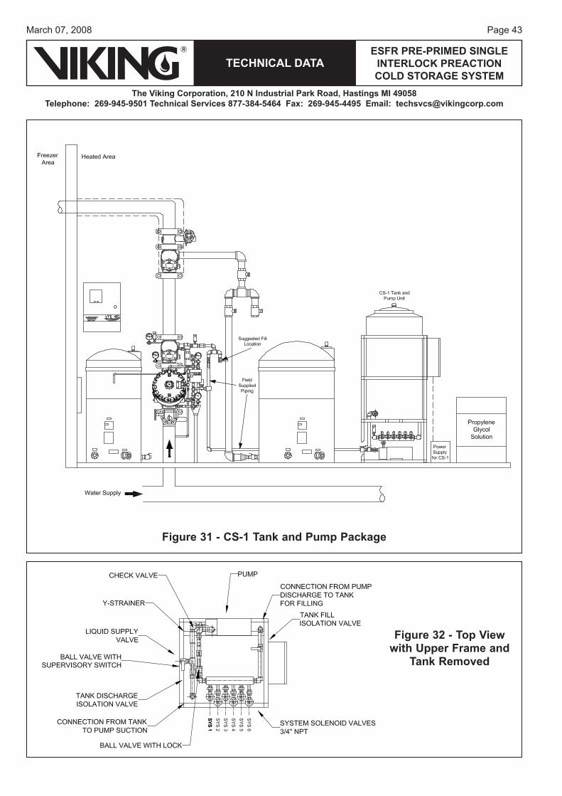
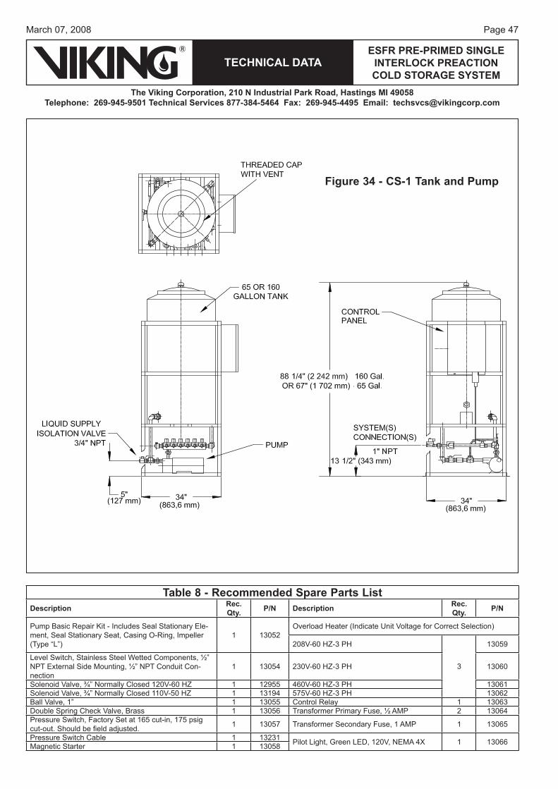
Figure 31 - CS-1 Tank and Pump Package
Figure 32 - Top View with Upper Frame and
Tank Removed
Page 44
TECHNICAL DATA
The Viking Corporation, 210 N Industrial Park Road, Hastings MI 49058Telephone: 269-945-9501 Technical Services 877-384-5464 Fax: 269-945-4495 Email: [email protected]
ESFR PRE-PRIMED SINGLE INTERLOCK PREACTION COLD STORAGE SYSTEM
March 07, 2008
B. Technical DataNOTE: The pressure switch (#6) on the CS-1 pump unit is factory set at cut-in pressure and cut-out pressure. The pressure downstream of the Easy Riser® Check Valve is maintained at 50 PSI Max to 35 PSI Min. (3.4 bar - 2.4 bar) by digital pressure switch (#5).
C. Installation1. Handling
Move the CS-1 on the shipping pallet as close to the final location as possible. Always lift the unit from underneath. Never lift the unit when it is full of liquid. Personal injury and/or equipment damage could result.Ensure that all equipment used to lift the CS-1 is capable of lifting the weight. Nylon straps and soft rigging devices should be used whenever possible to protect the components and finish.If the unit is being transported overhead, be sure that all personnel are alerted and safety pro-cedures are followed.
2. LocationInstall the CS-1 indoors in a clean, dry, non-corrosive environment. This equipment is not to be installed outdoors exposed to the weather. Position the CS-1 in an upright position on a solid, level, vibration-free surface capable of supporting the weight of the unit and liquid in the tank. Bolt the unit to the floor using the bolt holes provided in the frame. Always shim the unit level before bolting it to the floor. Install the CS-1 in a protected, well-ventilated area where the ambi-ent temperatures are between 40 °F and 100 °F (4.4 °C to 37.8 °C).Locate the CS-1 to allow access to supply and discharge connections. Clearance around the unit should be at least 24” (610 mm) on all sides for maintenance. Some jurisdictions require specific clearances around equipment. Check with all local Authorities to ensure compliance with applicable state, local, and national codes.
3. Piping and ConnectionsA slight downward slope from the supply container to the CS-1 supply valve connection is rec-ommended to maintain positive head on the pump inlet.Always use a backup wrench when making piping connections to avoid damage to the unit’s piping.Size piping between the CS-1 and the system to minimize pressure drop. Too small of a line size restricts pump flow, lowering capacity when filling the system. Lower capacity while fill-ing the system requires longer fill times. The sprinkler system must contain air vent/bleed valves at all local high points. These are used to let air out of the system while filling with antifreeze. Consult the system instructions for specifics.Individual check valves and isolation valves are required for each system. This allows system maintenance without disturbing other systems the CS-1 is connected to.Piping and/or hoses from the antifreeze supply containers to the unit should be sloped downhill slightly to provide positive head on the pump suction connection. These lines should be as large as possible and as short as possible to provide unrestricted flow to the pump while filling. A separate shut-off valve in the supply line is required.Unit piping is copper, brass and bronze. An aluminum manifold is included for mounting multiple system solenoids. Use dielectric unions to isolate copper piping from iron piping, if used, to reduce the possibility of electrolytic action on pipes and other components.
Page 45March 07, 2008
TECHNICAL DATAESFR PRE-PRIMED SINGLE
INTERLOCK PREACTION COLD STORAGE SYSTEM
The Viking Corporation, 210 N Industrial Park Road, Hastings MI 49058Telephone: 269-945-9501 Technical Services 877-384-5464 Fax: 269-945-4495 Email: [email protected]
All pipes should be de-burred and threaded to a proper depth and length before installation. Threads should be inspected for cleanliness and depth of cut. Good quality pipe compound should be used to ensure a good, leak-tight fit of piping components.NOTE: Pipe must be supported separately from the CS-1. At no time should the CS-1 sup-port the weight or load of the pipe. Acceptable pipe mounting devices would be unistrut supports anchored to walls, hangers suspended from ceilings, or pedestals mounted from the floor. Be sure all pipe installation conforms to all building and fire codes.
4. Electrical ConnectionsSERIOUS PERSONAL INJURY AND DAMAGE TO THE CS-1 WILL OCCUR IF IT IS CONNECTED TO A POWER SOURCE OTHER THAN THE VOLTAGE LISTED ON THE DATA TAG. THE MANUFACTURER IS NOT LIABLE FOR DAMAGE DUE TO IMPROPER WIRING, PROTECTION, OR ELECTRICAL SERVICE INSTALLATION.When installing electrical service to this machine, comply with the National Electric Code as well as state and local building codes. Failure to install the proper electrical protection can result in personal injury, fire, equipment damage or death. The manufacturer is not responsible for damage or injury caused by lack of or improperly installed electrical protection.Electrical connection to the unit is made in the control enclosure. Connect appropriate supply power to the terminals provided. The supply wire must be of adequate size and no other equip-ment should be connected to the same circuit. An arrow on the pump indicates the correct direc-tion of rotation. If the pump rotates in the opposite direction, reverse the rotation of the motor. Interchanging any two incoming 3-phase supply wires reverses rotation of 3-phase motors.WARNING: Operating the pump in the wrong direction may damage the pump. Verify pump rotation is correct before placing the unit in service. Make sure there is liquid on the suction side of the pump before checking rotation.Connect system inputs to the proper terminals in the CS-1 control enclosure. Each system pressure switch and alarm flow switch are connected as shown on the electrical schematic.NOTE: All system inputs must be connected before operating the unit. System valves will not respond unless the system pressure switch and flow alarm switch are con-nected correctly.
5. Start-UpThe following points must be verified before putting the unit into service. Correct any discrepan-cies before operating the unit:
The unit is bolted to a firm level surface.Area temperature will always remain between 40 °F and 100 °F (4.4 °C to 37.8 °C).Dielectric unions, if needed, are installed between the pump station piping and system piping.All piping to and from the pump station is independently supported and does not place any strain on the unit’s piping.Power supplied to the unit is appropriate.Pump rotation has been checked and is correct.System inputs are connected according to the electrical schematic. All pressure switches are set or programmed correctly.Air can be vented from the system when filling with antifreeze.
•••
•
•••
•
Page 46
TECHNICAL DATA
The Viking Corporation, 210 N Industrial Park Road, Hastings MI 49058Telephone: 269-945-9501 Technical Services 877-384-5464 Fax: 269-945-4495 Email: [email protected]
ESFR PRE-PRIMED SINGLE INTERLOCK PREACTION COLD STORAGE SYSTEM
March 07, 2008
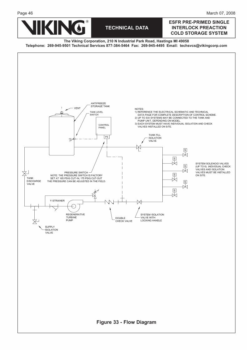
Figure 33 - Flow Diagram
Page 47March 07, 2008
TECHNICAL DATAESFR PRE-PRIMED SINGLE
INTERLOCK PREACTION COLD STORAGE SYSTEM
The Viking Corporation, 210 N Industrial Park Road, Hastings MI 49058Telephone: 269-945-9501 Technical Services 877-384-5464 Fax: 269-945-4495 Email: [email protected]
Figure 34 - CS-1 Tank and Pump
Table 8 - Recommended Spare Parts ListDescription Rec.
Qty. P/N Description Rec. Qty. P/N
Pump Basic Repair Kit - Includes Seal Stationary Ele-ment, Seal Stationary Seat, Casing O-Ring, Impeller (Type “L”)
1 13052Overload Heater (Indicate Unit Voltage for Correct Selection)
208V-60 HZ-3 PH
3
13059
Level Switch, Stainless Steel Wetted Components, ½” NPT External Side Mounting, ½” NPT Conduit Con-nection
1 13054 230V-60 HZ-3 PH 13060
Solenoid Valve, ¾” Normally Closed 120V-60 HZ 1 12955 460V-60 HZ-3 PH 13061Solenoid Valve, ¾” Normally Closed 110V-50 HZ 1 13194 575V-60 HZ-3 PH 13062Ball Valve, 1” 1 13055 Control Relay 1 13063Double Spring Check Valve, Brass 1 13056 Transformer Primary Fuse, ½ AMP 2 13064Pressure Switch, Factory Set at 165 cut-in, 175 psig cut-out. Should be fi eld adjusted. 1 13057 Transformer Secondary Fuse, 1 AMP 1 13065
Pressure Switch Cable 1 13231 Pilot Light, Green LED, 120V, NEMA 4X 1 13066Magnetic Starter 1 13058
Page 48
TECHNICAL DATA
The Viking Corporation, 210 N Industrial Park Road, Hastings MI 49058Telephone: 269-945-9501 Technical Services 877-384-5464 Fax: 269-945-4495 Email: [email protected]
ESFR PRE-PRIMED SINGLE INTERLOCK PREACTION COLD STORAGE SYSTEM
March 07, 2008
Table 10 - Inputs and OutputsInputs Outputs
Input 1 “Manual” position of Hand-Off- Auto Switch Output 1 “Power On” lightInput 2 “Auto” position of Hand-Off- Auto Switch Output 2 Pump Motor Starter Coil and “Pump” lightInput 3 Pressure Switch of Pumping Unit Output 3 System 1 Solenoid ValveInput 4 Tank Level Switch Output 4 System 2 Solenoid ValveInput 5 System 1 Inputs Output 5 System 3 Solenoid ValveInput 6 System 2 Inputs Output 6 System 4 Solenoid ValveInput 7 System 3 Inputs Output 7 System 5 Solenoid ValveInput 8 System 4 Inputs Output 8 System 6 Solenoid ValveInput 9 System 5 Inputs Output 9 Level Switch Relay Coil
Input 10 System 6 InputsInput 11 Switch A – Down PositionInput 12 Switch A – Up PositionInput 13 Switch B – Down PositionInput 14 Switch B – Up Position
Table 9 - CS-1 Schematic Drawing NumbersDrawing Number Manual Page
60Hz 50Hz 60Hz 50HzSingle Riser 13050-1 13051-1 60-61 72-73
Two Risers 13050-2 13051-2 62-63 74-75
Three Risers 13050-3 13051-3 64-65 76-77
Four Risers 13050-4 13051-4 66-67 78-79
Five Risers 13050-5 13051-5 68-69 80-81
Six Risers 13050-6 13051-6 70-71 82-83
Table 11 - Control LogicOutput 1 “Power On” light Output 1 on when: Input 1 or Input 2 are on.
Output 2Pump Motor Starter Coil and “Pump” light
Output 2 on when: (Manual Mode System and Tank Filling) Input 1 on + Input 3 on. -or-
(Automatic Mode) Input 2 on + Input 3 on + Input 4 on +And Internal Timer times to 10 minutes. The timer be-gins when Manual or Automatic mode is started and is reset when pump turns off in Automatic Mode.
Output 3 System 1 Solenoid Valve
Output 3 on when: (Manual Mode) Input 1 on and Input 5 on and Input 12 on and Input 13 off and Input 14 off.
-or- (Automatic Mode) Input 2 on and Input 5 on.
Output 4 System 2 Solenoid Valve
Output 4 on when: (Manual Mode) Input 1 on and Input 6 on and Input 11 on and Input 13 off and Input 14 off.
-or- (Automatic Mode) Input 2 on and Input 6 on.
Output 5 System 3 Solenoid Valve
Output 5 on when: (Manual Mode) Input 1 on and Input 7 on and Input 11 off and Input 12 off and Input 14 on.
-or- (Automatic Mode) Input 2 on and Input 7 on.
Output 6 System 4 Solenoid Valve
Output 6 on when: (Manual Mode) Input 1 on and Input 8 on and Input 11 off and Input 12 off and Input 13 on. -or- (Automatic Mode) Input 2 on and Input 8 on.
Output 7 System 5 Solenoid Valve
Output 7 on when: (Manual Mode) Input 1 on and Input 9 on and Input 12 on and Input 14 on. -or- (Automatic Mode) Input 2 on and Input 9 on.
Output 8 System 6 Solenoid Valve
Output 8 on when: (Manual Mode) Input 1 on and Input 10 on and Input 11 on and Input 13 on. -or- (Automatic Mode) Input 2 on and Input 10 on.
Output 9 Level Switch Relay Coil
Output 9 on when: Input 4 on.
Page 49March 07, 2008
TECHNICAL DATAESFR PRE-PRIMED SINGLE
INTERLOCK PREACTION COLD STORAGE SYSTEM
The Viking Corporation, 210 N Industrial Park Road, Hastings MI 49058Telephone: 269-945-9501 Technical Services 877-384-5464 Fax: 269-945-4495 Email: [email protected]
D. CS-1 Control Scheme1. Pump Operation
The pressure switch mounted on the CS-1 controls pump operation. When the pressure at the CS-1 drops, the pump will turn on until the pressure at the CS-1 rises above a set level. In “Automatic” mode, pump operation is inhibited if the level of liquid in the unit’s storage tank drops below the level switch height.In “Manual” mode, the pump operates when CS-1 pressure drops, a system valve is selected, if that system pressure is not met, and there is no alarm condition. The pump can also fill the tank in Manual mode. For tank filling, the level switch position is not used and the operator must start and stop the pump, using the “Man” position of the Man-Off-Auto Switch on the control panel.In Automatic mode, there is a 10-minute time delay between pump operations. After the 10-minute delay, the pump operates if the CS-1 pressure drops and tank fluid level is above the level switch height. When the pump shuts off, the 10-minute timer starts again and the pump will not operate until 10 minutes is complete.
2. System Solenoid Valve OperationEach system (riser) pressure switch and alarm pressure switch contacts are connected in se-ries to one input on the PLC. The system pressure switch closes on falling pressure. The alarm pressure switch normally closed contacts are used and open in the alarm condition.In Automatic mode, each system solenoid valve opens if its system pressure drops to a low-pressure condition and there is no alarm pressure signal. In manual mode, each sys-tem valve is selected by means of two selector switches and the solenoid valve opens as long as system pressure is below the set-point value and there is no system alarm.Note: To operate in manual mode, all switches must be wired.
3. Level Switch Relay Coil OperationThe level switch relay coil is energized when the tank level is above the level switch height. This is when tank level is satisfied. The switch relay coil de-energizes when tank level drops to the level switch height, at low tank level.
E. Filling the Reservoir TankThe CS-1 has been designed to fill the reservoir tank using either of two methods: gravity fill or pumped fill. NOTE: This is NOT a self-priming pump. Manually prime or fill the reservoir for prime.NOTE: Never leave the unit unattended when filling the system or tank. Running the pump dry, without liquid, will damage pump seals and possibly damage pump impeller.Follow the steps below:1. Gravity Fill:
Turn off and isolate the electrical supply to the unit.Close Supply Isolation valve.Connect the antifreeze supply container to the supply isolation valve. A flexible hose may be used, but must not restrict the flow from the supply container to the valve. An additional isolation valve must be installed in the line between the supply container and unit’s supply isolation valve. Open the shut off valve on the supply container and supply isolation valve on the CS-1.
1.2.3.
4.
Page 50
TECHNICAL DATA
The Viking Corporation, 210 N Industrial Park Road, Hastings MI 49058Telephone: 269-945-9501 Technical Services 877-384-5464 Fax: 269-945-4495 Email: [email protected]
ESFR PRE-PRIMED SINGLE INTERLOCK PREACTION COLD STORAGE SYSTEM
March 07, 2008
Open the pump suction isolation valve and allow liquid to enter the reservoir tank. If there is enough liquid in the supply container, the tank may be filled completely using this method. The tank is full when the liquid level rises to the top of the straight section of the tank.
2. Pump Assist Fill:If there is not sufficient liquid in the supply container to fill the tank or the tank fills too slowly, the pump on the CS-1 may be manually operated to speed up this process. Follow steps 1 to 4 above and 2 to 5 below to fill the storage tank using the pump. A slight downward slope from the supply container to the valve connection is required to prime the pump and maintain posi-tive head on the pump inlet. Always use a backup wrench when making piping connections to avoid damage to the unit’s piping.
Close the tank discharge isolation valve and open the tank fill isolation valve.With the CS-1 “OFF-ON” switch in the “OFF” position, turn on power supply to the unit.Position switches “A” and “B” in the center/off position. Switch the “Man-O-AUTO” switch on the unit control panel to “Man” and the “OFF-ON” switch to “ON”. Liquid will begin to fill the storage tank at the fill connection.Be careful to observe the liquid level to prevent overfilling. When the liquid level reaches the top of the straight section of tank, switch the unit’s “Man-O-AUTO” switch to “O”.Close the liquid supply isolation and tank fill isolation valves. Open the tank discharge isolation valve.
F. Filling SystemsA suitable portable pump can be utilized to fill the system. (The CS-1 pump can be used for fill-ing the system initially at 15 GPM (56 l/min) to 100 ft head pressure or system static pressure. However, it is a less efficient pump for filling the system because of the duration of time required to do so. To fill the system, the system solenoid on the CS-1 is connected to the liquid supply isolation valve of the Easy Riser® Check Valve for that system. All pressure switches must be installed and set. The system to be filled is selected using two toggle switches on the CS-1 control enclosure. Antifreeze from the supply is pumped to the system piping. Pump operation is manually controlled during the fill process. The CS-1 pump is to be utilized to bring the solution to maintenance pres-sure, and is designed to maintain system pressure once the system is initially filled. Appropriate vent/bleed valves must be installed on each system’s piping at all local high points to allow air to escape while liquid fills the system.NOTE: Never leave the unit unattended when filling the system. Running the pump dry, with-out liquid, will damage pump seals and possibly damage the pump impeller.
Follow the steps below:Turn off and isolate the electrical supply to the unit.Close the liquid supply valve and Tank Fill isolation valves.If not already connected to fill the storage tank, connect the antifreeze supply container to the liquid supply valve. A flexible hose may be used, but must not restrict the flow from the sup-ply container to the valve. An additional isolation valve must be installed in the line between the supply container and unit’s liquid supply valve. A slight downward slope from the supply container to the unit’s valve connection is required to prime the pump and maintain positive head on pump inlet. Always use a backup wrench when making piping connections to avoid damage to the unit’s piping.Open the shut-off valve on the supply container and liquid supply valve on the CS-1.Open high-point vent/bleed valves on the system.
5.
1.2.3.
4.
5.
1.2.3.
4.5.
Page 51March 07, 2008
TECHNICAL DATAESFR PRE-PRIMED SINGLE
INTERLOCK PREACTION COLD STORAGE SYSTEM
The Viking Corporation, 210 N Industrial Park Road, Hastings MI 49058Telephone: 269-945-9501 Technical Services 877-384-5464 Fax: 269-945-4495 Email: [email protected]
Table 12 - Input Descriptions
Input Description1 “Man” position of Hand-Off-
Auto Switch2 “Auto” position of Hand-
Off- Auto Switch3 Pressure Switch of
Pumping Unit4 Tank Level Switch5 System 1 Inputs6 System 2 Inputs7 System 3 Inputs8 System 4 Inputs9 System 5 Inputs
10 System 6 Inputs11 Switch A – Down Position12 Switch A – Up Position13 Switch B – Down Position14 Switch B – Up Position
Table 13 - Output DescriptionsOutput Description Control Logic
1 “Power On” light Output 1 on when: Input 1 or Input 2 are on.2 Pump Motor
Starter Coil and “Pump” light
Output 2 on when: (Manual Mode System and Tank Filling) Input 1 on + Input 3 on. OR(Automatic Mode) Input 2 on + Input 3 on + Input 4 on and Internal Timer times to 10 minutes. The timer begins when Manual or Automatic mode is started and is reset when pump turns off in Automatic Mode.
3 System 1 Solenoid Valve
Output 3 on when: (Manual Mode) Input 1 on and Input 5 on and Input 12 on and Input 13 off and Input 14 off. OR(Automatic Mode) Input 2 on and Input 5 on.
4 System 2 Solenoid Valve
Output 4 on when: (Manual Mode) Input 1 on and Input 6 on and Input 11 on and Input 13 off and Input 14 off. OR(Automatic Mode) Input 2 on and Input 6 on.
5 System 3 Solenoid Valve
Output 5 on when:(Manual Mode) Input 1 on and Input 7 on and Input 11 off and Input 12 off and Input 14 on. OR(Automatic Mode) Input 2 on and Input 7 on.
6 System 4 Solenoid Valve
Output 6 on when:(Manual Mode) Input 1 on and Input 8 on and Input 11 off and Input 12 off and Input 13 on. OR(Automatic Mode) Input 2 on and Input 8 on.
7 System 5 Solenoid Valve
Output 7 on when:(Manual Mode) Input 1 on and Input 9 on and Input 12 on and Input 14 on. OR(Automatic Mode) Input 2 on and Input 9 on.
8 System 6 Solenoid Valve
Output 8 on when:(Manual Mode) Input 1 on and Input 10 on and Input 11 on and Input 13 on. OR(Automatic Mode) Input 2 on and Input 10 on.
9 Level Switch Relay Coil
Output 9 on when: Input 4 on.
Select system to be filled using switches “A” and “B”. Use Table 14 or the table on the CS-1 Panel to determine switch “A” and “B” position.With the CS-1’s “OFF-ON” switch in the “OFF” position, turn on the power supply to the unit. Switch the “Man-O-AUTO” switch on the unit control panel to “Man”. Turn the “Off-On” switch to “ON”. Liquid will begin to fill the selected system.As the system fills, monitor the system vent/bleed valves. Close each valve when liquid leaks from it.When the liquid leaks from the uppermost vent/bleed valve, close the vent valve. The system pressure switch will close that system’s solenoid valve when set pressure is established. The pump pressure switch will turn the pump off when set pressure is established.If another system is to be filled, turn the “Man-O-AUTO” switch to “O” and select the next system using switches A and B.Turn the “Man-O-AUTO” switch to “Man” and repeat steps 8 through 10.After filling all systems and the CS-1 tank, close the liquid supply valve.All air must be out of the system before switching the unit to maintenance mode. Follow the system manufacturer’s recommendations to ensure all air is removed.
G. Operating in Maintenance Mode: AutomaticAs previously stated, the CS-1 is designed to maintain the antifreeze pressure in the sprinkler sys-tem at a supervisory pressure of 50 PSI (3.4 Bar). A pressure switch installed in the pump discharge line operates the pump between two pressures sensed in the unit’s piping. A pressure switch on each system sends a signal to the CS-1 to open and close that system’s solenoid valve.Ensure all air is removed from system piping before placing the unit in automatic operation.Liquid level in the storage tank must be above the level switch height or pump operation is inhib-ited.
6.
7.
8.
9.
10.
11.
12.13.14.
Page 52
TECHNICAL DATA
The Viking Corporation, 210 N Industrial Park Road, Hastings MI 49058Telephone: 269-945-9501 Technical Services 877-384-5464 Fax: 269-945-4495 Email: [email protected]
ESFR PRE-PRIMED SINGLE INTERLOCK PREACTION COLD STORAGE SYSTEM
March 07, 2008
Close the liquid supply and tank fill isolation valves. Open the tank discharge isolation valve and system liquid supply isolation valve.With the “ON-OFF” switch “ON”, switch the “Man-O-AUTO” switch to the “AUTO” position. The CS-1 is now operating in Maintenance mode.NOTE: The CS-1 control system uses a time delay relay, set at 10 minutes, to limit pump opera-tion to six times per hour maximum. When the unit is first energized in “AUTO”, pump operation is delayed for 10 minutes.After 10 minutes, if the CS-1 piping is below the unit’s pressure switch setting, the pump motor will operate, raising CS-1 manifold pressure.The pump will turn off at the pressure switch cutout pressure.Each system’s solenoid valve will open in response to system pressure switch.
Table 14 - Switch Settings
System Selected Switch A Position Switch B PositionNo System - Tank Fill Centered Centered
System 1 Up Centered
System 2 Down Centered
System 3 Centered Up
System 4 Centered Down
System 5 Up Up
System 6 Down Down
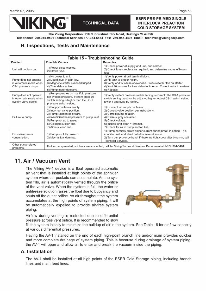
Page 53March 07, 2008
TECHNICAL DATAESFR PRE-PRIMED SINGLE
INTERLOCK PREACTION COLD STORAGE SYSTEM
The Viking Corporation, 210 N Industrial Park Road, Hastings MI 49058Telephone: 269-945-9501 Technical Services 877-384-5464 Fax: 269-945-4495 Email: [email protected]
11. Air / Vacuum VentThe Viking AV-1 device is a float operated automatic air vent that is installed at high points of the sprinkler system where air pockets can accumulate. As the sys-tem fills, air is automatically vented through the orifice of the vent valve. When the system is full, the water or antifreeze solution raises the float due to buoyancy and shuts off the outlet orifice. As air throughout the system accumulates at the high points of system piping, it will be automatically expelled to provide air-free system piping.Airflow during venting is restricted due to differential pressure across vent orifice. It is recommended to slow fill the system initially to minimize the buildup of air in the system. See Table 16 for air flow capacity at various differential pressures.Having the AV-1 installed on the end of each high-point branch line and/or main provides quicker and more complete drainage of system piping. This is because during drainage of system piping, the AV-1 will open and allow air to enter and break the vacuum inside the piping.
A. InstallationThe AV-1 shall be installed at all high points of the ESFR Cold Storage piping, including branch lines and main feed lines.
Table 15 - Troubleshooting GuideProblem Possible Causes Remedies
Unit will not turn on. 1) Power disconnected.2) Blown fuse.
1) Check power at supply and unit, and correct.2) Check fuses, replace as required, and determine cause of blown fuse.
Pump does not operate in Automatic mode when CS-1 pressure drops.
1) No power to unit.2) Liquid level in tank low.3) Magnetic starter overload tripped.4) Time delay active.5) Pump motor defective.
1) Verify power at unit terminal block.2) Fill tank to proper height.3) Verify and fi x cause of overload. Press reset button on starter.4) Wait 10 minutes for time delay to time out. Correct leaks in system.5) Replace.
Pump does not operate in Automatic mode when system valve opens.
1) Pump operates on manifold pressure, not system pressure. System pressure switch setting is higher than the CS-1 pressure switch setting.
1) Verify system pressure switch setting is correct. The CS-1 pressure switch setting must not be adjusted higher. Adjust CS-1 switch setting lower if approved by factory.
Failure to pump.
1) Supply container empty.2) Incorrect valve position.3) Pump rotation backward.4) Insuffi cient head pressure to pump inlet.5) Pump not up to speed.6) Clogged suction line.7) Air in suction line.
1) Connect full supply container.2) Correct valve position per instructions.3) Correct pump rotation.4) Raise supply container.5) Check voltage.6) Inspect and clean Y-Strainer.7) Check for air in pump suction line.
Excessive power consumption.
1) Pump not fully broken in.2) Mechanical damage.
1) Pump normally draws higher current during break-in period. This condition will work itself out after several weeks.2) Turn pump over by hand. If there are tight spots after break-in, call Technical Services.
Other pump-related problems. If other pump related problems are suspected, call the Viking Technical Services Department at 1-877-384-5464.
H. Inspections, Tests and Maintenance
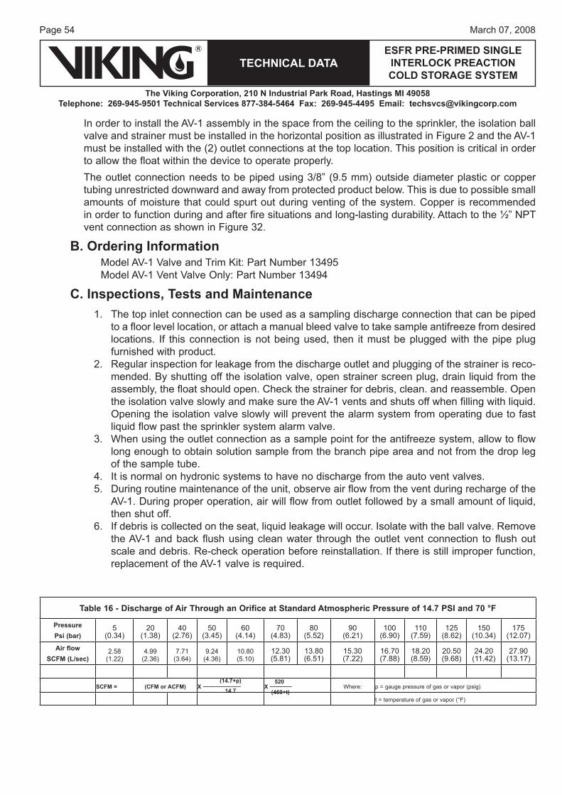
Page 54
TECHNICAL DATA
The Viking Corporation, 210 N Industrial Park Road, Hastings MI 49058Telephone: 269-945-9501 Technical Services 877-384-5464 Fax: 269-945-4495 Email: [email protected]
ESFR PRE-PRIMED SINGLE INTERLOCK PREACTION COLD STORAGE SYSTEM
March 07, 2008
Table 16 - Discharge of Air Through an Orifice at Standard Atmospheric Pressure of 14.7 PSI and 70 °F
PressurePsi (bar)
5(0.34)
20(1.38)
40(2.76)
50(3.45)
60(4.14)
70(4.83)
80(5.52)
90(6.21)
100(6.90)
110(7.59)
125(8.62)
150(10.34)
175(12.07)
Air flow SCFM (L/sec)
2.58(1.22)
4.99(2.36)
7.71(3.64)
9.24(4.36)
10.80(5.10)
12.30(5.81)
13.80(6.51)
15.30(7.22)
16.70(7.88)
18.20(8.59)
20.50(9.68)
24.20(11.42)
27.90(13.17)
(14.7+p) 520SCFM = (CFM or ACFM) X ____________ X _______ Where: p = gauge pressure of gas or vapor (psig)
14.7 (460+t)t = temperature of gas or vapor (°F)
In order to install the AV-1 assembly in the space from the ceiling to the sprinkler, the isolation ball valve and strainer must be installed in the horizontal position as illustrated in Figure 2 and the AV-1 must be installed with the (2) outlet connections at the top location. This position is critical in order to allow the float within the device to operate properly.The outlet connection needs to be piped using 3/8” (9.5 mm) outside diameter plastic or copper tubing unrestricted downward and away from protected product below. This is due to possible small amounts of moisture that could spurt out during venting of the system. Copper is recommended in order to function during and after fire situations and long-lasting durability. Attach to the ½” NPT vent connection as shown in Figure 32.
B. Ordering InformationModel AV-1 Valve and Trim Kit: Part Number 13495Model AV-1 Vent Valve Only: Part Number 13494
C. Inspections, Tests and MaintenanceThe top inlet connection can be used as a sampling discharge connection that can be piped to a floor level location, or attach a manual bleed valve to take sample antifreeze from desired locations. If this connection is not being used, then it must be plugged with the pipe plug furnished with product.Regular inspection for leakage from the discharge outlet and plugging of the strainer is reco-mended. By shutting off the isolation valve, open strainer screen plug, drain liquid from the assembly, the float should open. Check the strainer for debris, clean. and reassemble. Open the isolation valve slowly and make sure the AV-1 vents and shuts off when filling with liquid. Opening the isolation valve slowly will prevent the alarm system from operating due to fast liquid flow past the sprinkler system alarm valve.When using the outlet connection as a sample point for the antifreeze system, allow to flow long enough to obtain solution sample from the branch pipe area and not from the drop leg of the sample tube.It is normal on hydronic systems to have no discharge from the auto vent valves.During routine maintenance of the unit, observe air flow from the vent during recharge of the AV-1. During proper operation, air will flow from outlet followed by a small amount of liquid, then shut off.If debris is collected on the seat, liquid leakage will occur. Isolate with the ball valve. Remove the AV-1 and back flush using clean water through the outlet vent connection to flush out scale and debris. Re-check operation before reinstallation. If there is still improper function, replacement of the AV-1 valve is required.
1.
2.
3.
4.5.
6.
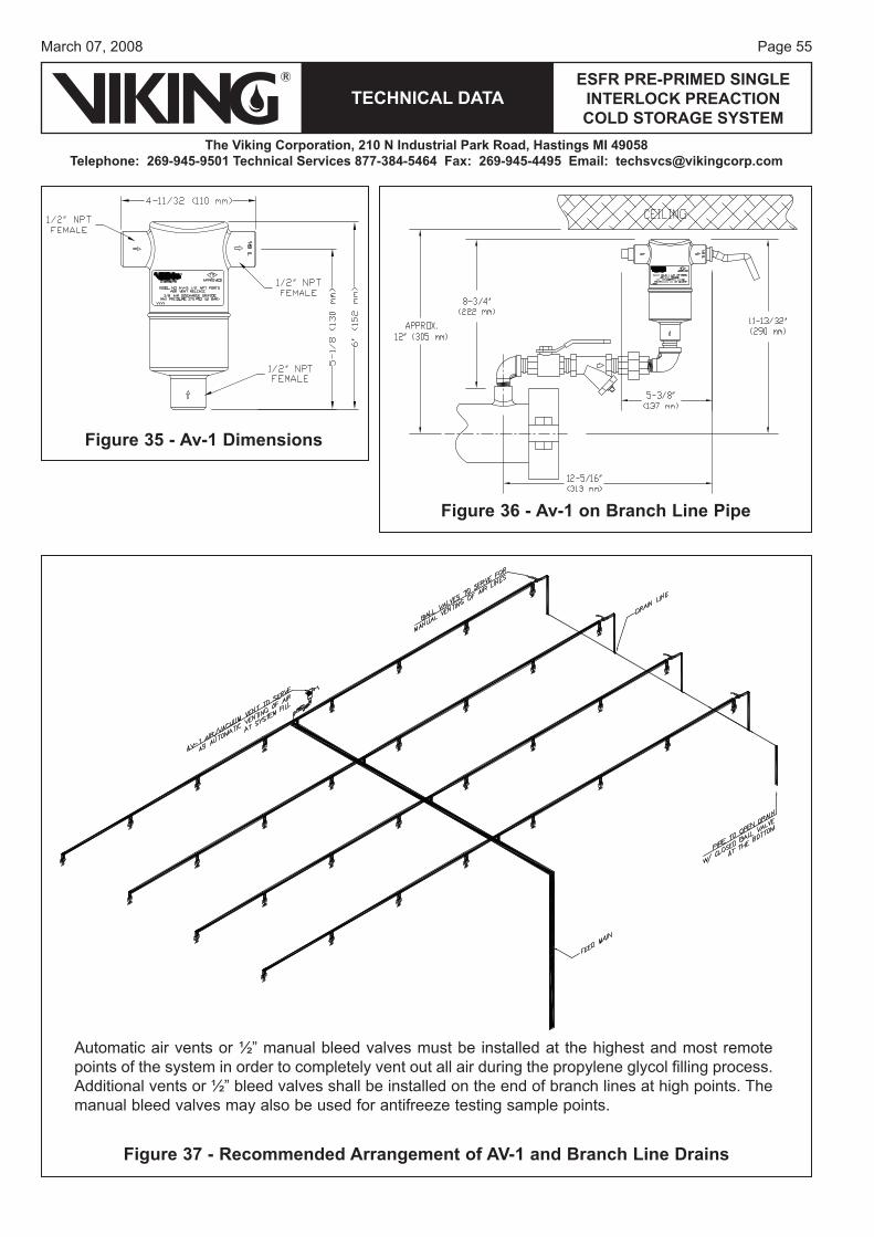
Page 55March 07, 2008
TECHNICAL DATAESFR PRE-PRIMED SINGLE
INTERLOCK PREACTION COLD STORAGE SYSTEM
The Viking Corporation, 210 N Industrial Park Road, Hastings MI 49058Telephone: 269-945-9501 Technical Services 877-384-5464 Fax: 269-945-4495 Email: [email protected]
Figure 35 - Av-1 Dimensions
Figure 36 - Av-1 on Branch Line Pipe
Automatic air vents or ½” manual bleed valves must be installed at the highest and most remotepoints of the system in order to completely vent out all air during the propylene glycol filling process.Additional vents or ½” bleed valves shall be installed on the end of branch lines at high points. Themanual bleed valves may also be used for antifreeze testing sample points.
Figure 37 - Recommended Arrangement of AV-1 and Branch Line Drains
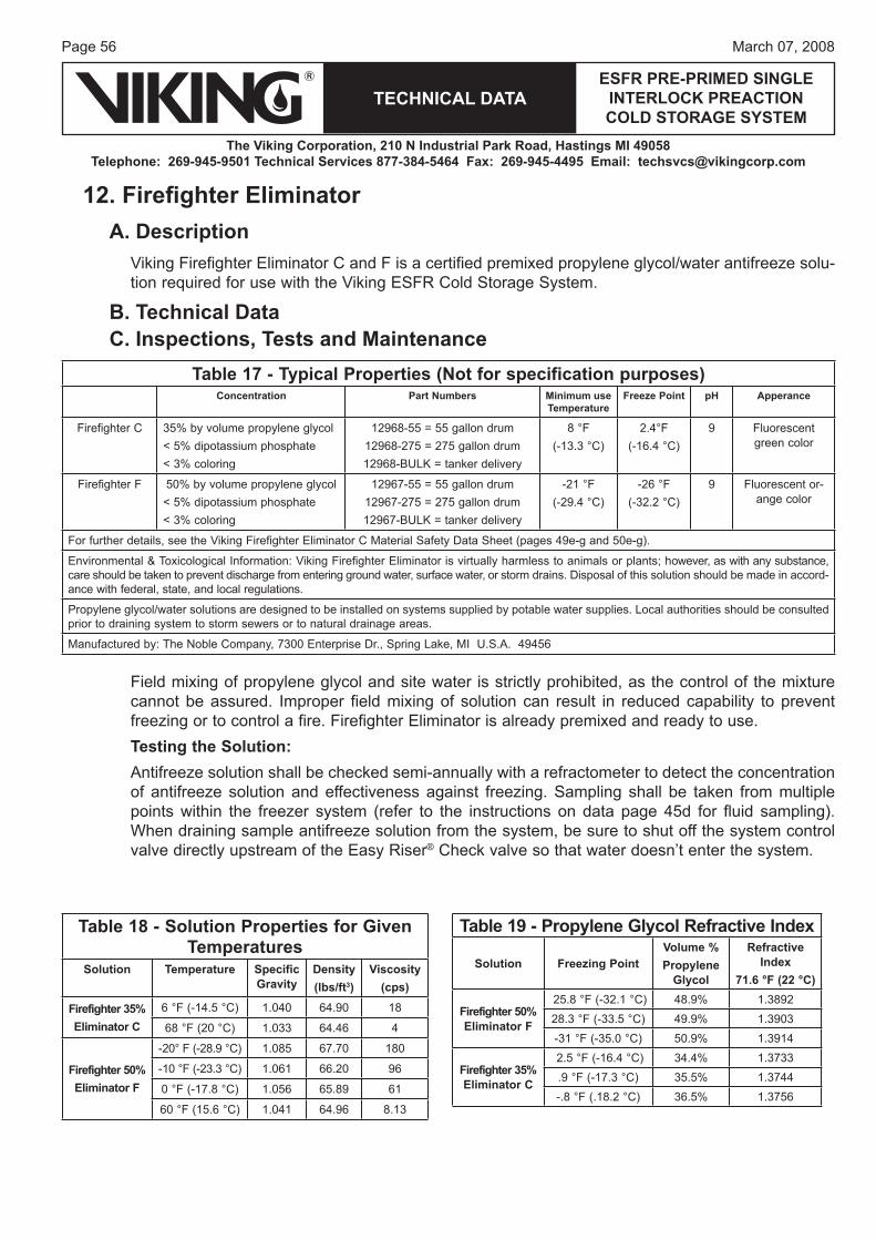
Page 56
TECHNICAL DATA
The Viking Corporation, 210 N Industrial Park Road, Hastings MI 49058Telephone: 269-945-9501 Technical Services 877-384-5464 Fax: 269-945-4495 Email: [email protected]
ESFR PRE-PRIMED SINGLE INTERLOCK PREACTION COLD STORAGE SYSTEM
March 07, 2008
12. Firefi ghter Eliminator A. Description
Viking Firefighter Eliminator C and F is a certified premixed propylene glycol/water antifreeze solu-tion required for use with the Viking ESFR Cold Storage System.
B. Technical DataC. Inspections, Tests and Maintenance
Field mixing of propylene glycol and site water is strictly prohibited, as the control of the mixture cannot be assured. Improper field mixing of solution can result in reduced capability to prevent freezing or to control a fire. Firefighter Eliminator is already premixed and ready to use.Testing the Solution: Antifreeze solution shall be checked semi-annually with a refractometer to detect the concentration of antifreeze solution and effectiveness against freezing. Sampling shall be taken from multiple points within the freezer system (refer to the instructions on data page 45d for fluid sampling). When draining sample antifreeze solution from the system, be sure to shut off the system control valve directly upstream of the Easy Riser® Check valve so that water doesn’t enter the system.
Table 17 - Typical Properties (Not for specification purposes)Concentration Part Numbers Minimum use
TemperatureFreeze Point pH Apperance
Firefighter C 35% by volume propylene glycol< 5% dipotassium phosphate< 3% coloring
12968-55 = 55 gallon drum12968-275 = 275 gallon drum12968-BULK = tanker delivery
8 °F (-13.3 °C)
2.4°F (-16.4 °C)
9 Fluorescent green color
Firefighter F 50% by volume propylene glycol< 5% dipotassium phosphate< 3% coloring
12967-55 = 55 gallon drum12967-275 = 275 gallon drum12967-BULK = tanker delivery
-21 °F(-29.4 °C)
-26 °F (-32.2 °C)
9 Fluorescent or-ange color
For further details, see the Viking Firefighter Eliminator C Material Safety Data Sheet (pages 49e-g and 50e-g).
Environmental & Toxicological Information: Viking Firefighter Eliminator is virtually harmless to animals or plants; however, as with any substance, care should be taken to prevent discharge from entering ground water, surface water, or storm drains. Disposal of this solution should be made in accord-ance with federal, state, and local regulations.
Propylene glycol/water solutions are designed to be installed on systems supplied by potable water supplies. Local authorities should be consulted prior to draining system to storm sewers or to natural drainage areas.
Manufactured by: The Noble Company, 7300 Enterprise Dr., Spring Lake, MI U.S.A. 49456
Table 19 - Propylene Glycol Refractive Index
Solution Freezing PointVolume % Propylene
Glycol
Refractive Index
71.6 °F (22 °C)
Firefighter 50% Eliminator F
25.8 °F (-32.1 °C) 48.9% 1.389228.3 °F (-33.5 °C) 49.9% 1.3903-31 °F (-35.0 °C) 50.9% 1.3914
Firefighter 35%Eliminator C
2.5 °F (-16.4 °C) 34.4% 1.3733.9 °F (-17.3 °C) 35.5% 1.3744-.8 °F (.18.2 °C) 36.5% 1.3756
Table 18 - Solution Properties for Given Temperatures
Solution Temperature Specific Gravity
Density(lbs/ft3)
Viscosity (cps)
Firefighter 35% Eliminator C
6 °F (-14.5 °C) 1.040 64.90 18
68 °F (20 °C) 1.033 64.46 4
Firefighter 50% Eliminator F
-20° F (-28.9 °C) 1.085 67.70 180
-10 °F (-23.3 °C) 1.061 66.20 96
0 °F (-17.8 °C) 1.056 65.89 61
60 °F (15.6 °C) 1.041 64.96 8.13
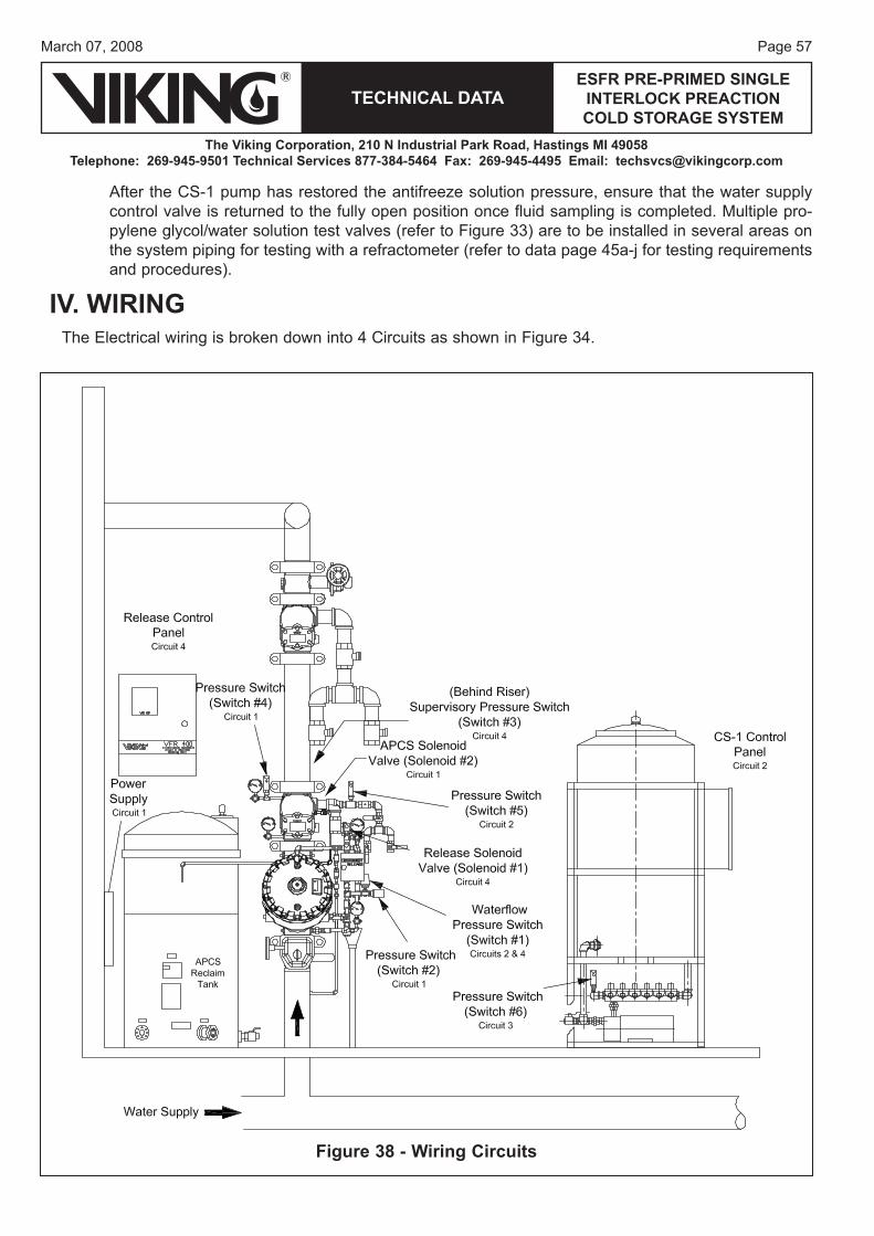
Page 57March 07, 2008
TECHNICAL DATAESFR PRE-PRIMED SINGLE
INTERLOCK PREACTION COLD STORAGE SYSTEM
The Viking Corporation, 210 N Industrial Park Road, Hastings MI 49058Telephone: 269-945-9501 Technical Services 877-384-5464 Fax: 269-945-4495 Email: [email protected]
After the CS-1 pump has restored the antifreeze solution pressure, ensure that the water supply control valve is returned to the fully open position once fluid sampling is completed. Multiple pro-pylene glycol/water solution test valves (refer to Figure 33) are to be installed in several areas on the system piping for testing with a refractometer (refer to data page 45a-j for testing requirements and procedures).
IV. WIRING The Electrical wiring is broken down into 4 Circuits as shown in Figure 34.
Figure 38 - Wiring Circuits
Page 58
TECHNICAL DATA
The Viking Corporation, 210 N Industrial Park Road, Hastings MI 49058Telephone: 269-945-9501 Technical Services 877-384-5464 Fax: 269-945-4495 Email: [email protected]
ESFR PRE-PRIMED SINGLE INTERLOCK PREACTION COLD STORAGE SYSTEM
March 07, 2008
Figure 39 - Circuit 1
1. Wiring Circuit 1Wiring circuit 1 is described in Section IV.5.A - Cold Storage Trim with Automatic Pressure Control System.
Digital Pressure Switch PinConnections
L1
N
N.C
RELAY
CIRCUIT
Page 59March 07, 2008
TECHNICAL DATAESFR PRE-PRIMED SINGLE
INTERLOCK PREACTION COLD STORAGE SYSTEM
The Viking Corporation, 210 N Industrial Park Road, Hastings MI 49058Telephone: 269-945-9501 Technical Services 877-384-5464 Fax: 269-945-4495 Email: [email protected]
Figure 40 - Circuit 2
2. Wiring Cicuit 2
Page 60
TECHNICAL DATA
The Viking Corporation, 210 N Industrial Park Road, Hastings MI 49058Telephone: 269-945-9501 Technical Services 877-384-5464 Fax: 269-945-4495 Email: [email protected]
ESFR PRE-PRIMED SINGLE INTERLOCK PREACTION COLD STORAGE SYSTEM
March 07, 2008
3. Wiring Circuit 3Wiring Circuit 3 is comprised of the CS-1 solenoid valve(s) and the CS-1 pressure switch. There are 12 wiring diagrams in the following pages, one for each model CS-1 Tank and Pump Package.
Table 20 - CS-1 Schematic Drawing NumbersDrawing Number Manual Page
60Hz 50Hz 60Hz 50HzSingle Riser 13050-1 13051-1 60-61 72-73
Two Risers 13050-2 13051-2 62-63 74-75
Three Risers 13050-3 13051-3 64-65 76-77
Four Risers 13050-4 13051-4 66-67 78-79
Five Risers 13050-5 13051-5 68-69 80-81
Six Risers 13050-6 13051-6 70-71 82-83
Page 61March 07, 2008
TECHNICAL DATAESFR PRE-PRIMED SINGLE
INTERLOCK PREACTION COLD STORAGE SYSTEM
The Viking Corporation, 210 N Industrial Park Road, Hastings MI 49058Telephone: 269-945-9501 Technical Services 877-384-5464 Fax: 269-945-4495 Email: [email protected]
Figure 41a - Wiring Diagram 13050-160 Hz - 1 Solenoid
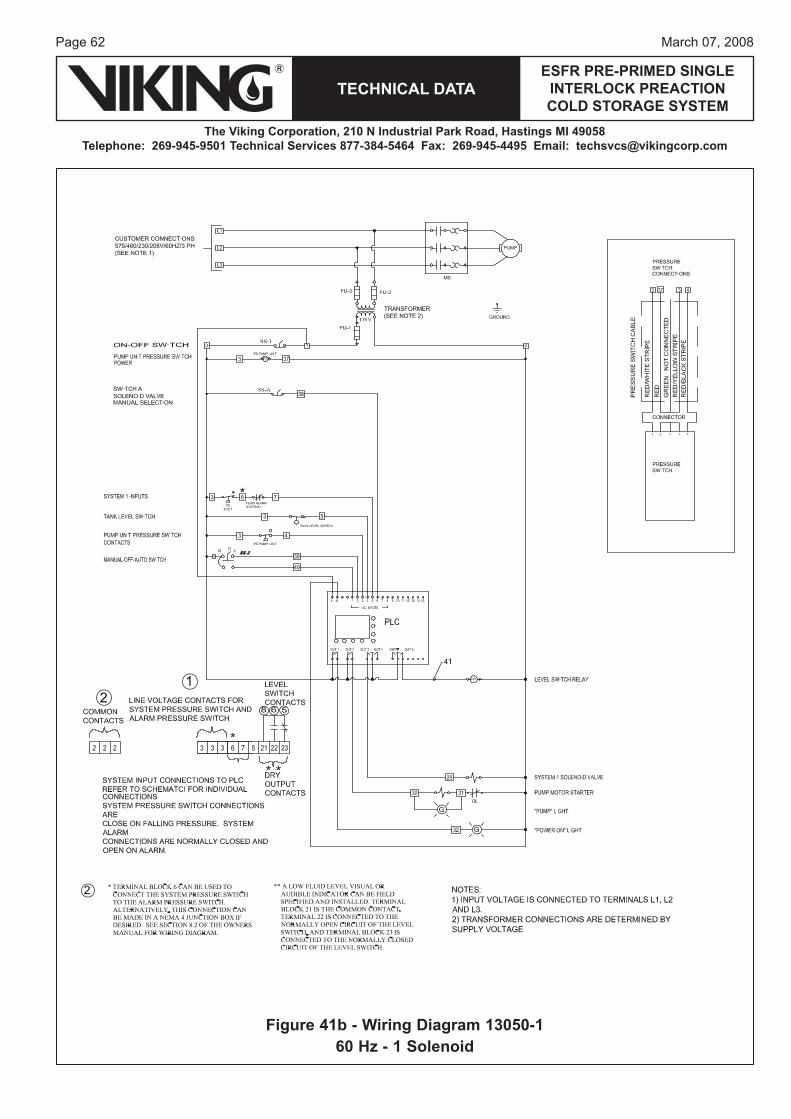
Page 62
TECHNICAL DATA
The Viking Corporation, 210 N Industrial Park Road, Hastings MI 49058Telephone: 269-945-9501 Technical Services 877-384-5464 Fax: 269-945-4495 Email: [email protected]
ESFR PRE-PRIMED SINGLE INTERLOCK PREACTION COLD STORAGE SYSTEM
March 07, 2008
Figure 41b - Wiring Diagram 13050-160 Hz - 1 Solenoid
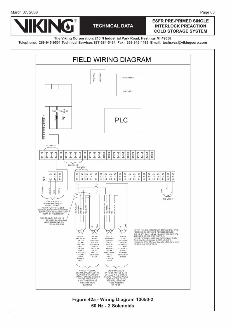
Page 63March 07, 2008
TECHNICAL DATAESFR PRE-PRIMED SINGLE
INTERLOCK PREACTION COLD STORAGE SYSTEM
The Viking Corporation, 210 N Industrial Park Road, Hastings MI 49058Telephone: 269-945-9501 Technical Services 877-384-5464 Fax: 269-945-4495 Email: [email protected]
Figure 42a - Wiring Diagram 13050-260 Hz - 2 Solenoids
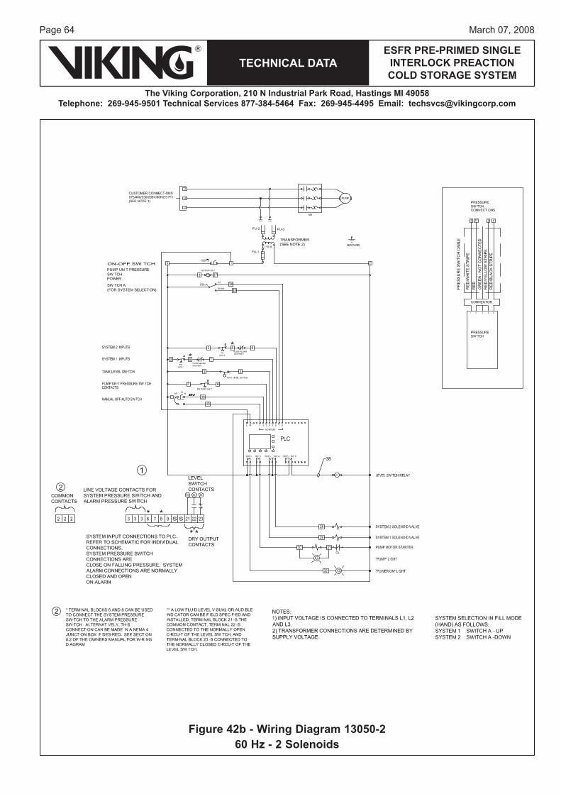
Page 64
TECHNICAL DATA
The Viking Corporation, 210 N Industrial Park Road, Hastings MI 49058Telephone: 269-945-9501 Technical Services 877-384-5464 Fax: 269-945-4495 Email: [email protected]
ESFR PRE-PRIMED SINGLE INTERLOCK PREACTION COLD STORAGE SYSTEM
March 07, 2008
Figure 42b - Wiring Diagram 13050-260 Hz - 2 Solenoids
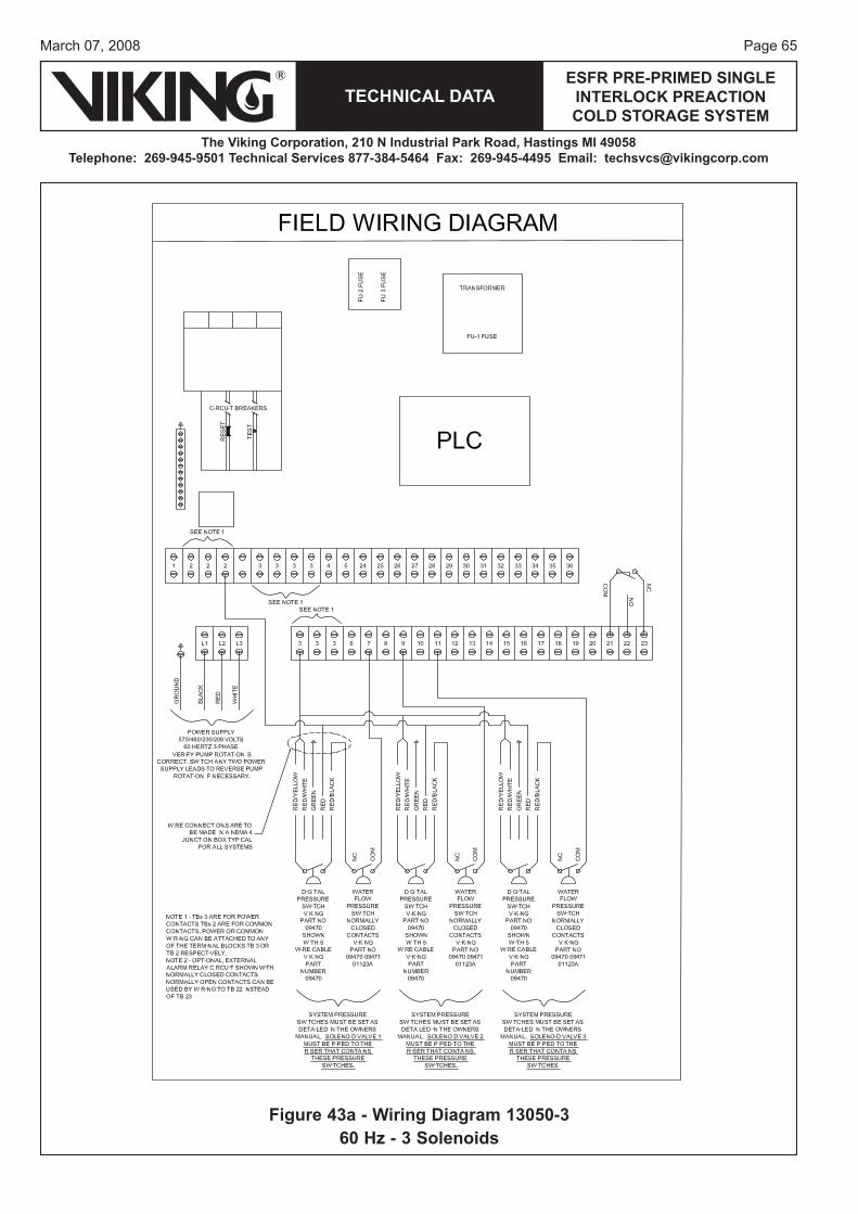
Page 65March 07, 2008
TECHNICAL DATAESFR PRE-PRIMED SINGLE
INTERLOCK PREACTION COLD STORAGE SYSTEM
The Viking Corporation, 210 N Industrial Park Road, Hastings MI 49058Telephone: 269-945-9501 Technical Services 877-384-5464 Fax: 269-945-4495 Email: [email protected]
Figure 43a - Wiring Diagram 13050-360 Hz - 3 Solenoids
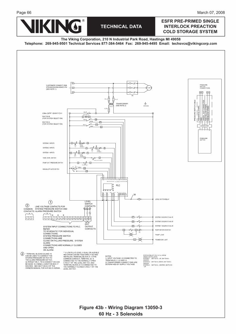
Page 66
TECHNICAL DATA
The Viking Corporation, 210 N Industrial Park Road, Hastings MI 49058Telephone: 269-945-9501 Technical Services 877-384-5464 Fax: 269-945-4495 Email: [email protected]
ESFR PRE-PRIMED SINGLE INTERLOCK PREACTION COLD STORAGE SYSTEM
March 07, 2008
Figure 43b - Wiring Diagram 13050-360 Hz - 3 Solenoids

Page 67March 07, 2008
TECHNICAL DATAESFR PRE-PRIMED SINGLE
INTERLOCK PREACTION COLD STORAGE SYSTEM
The Viking Corporation, 210 N Industrial Park Road, Hastings MI 49058Telephone: 269-945-9501 Technical Services 877-384-5464 Fax: 269-945-4495 Email: [email protected]
Figure 44a - Wiring Diagram 13050-460 Hz - 4 Solenoids
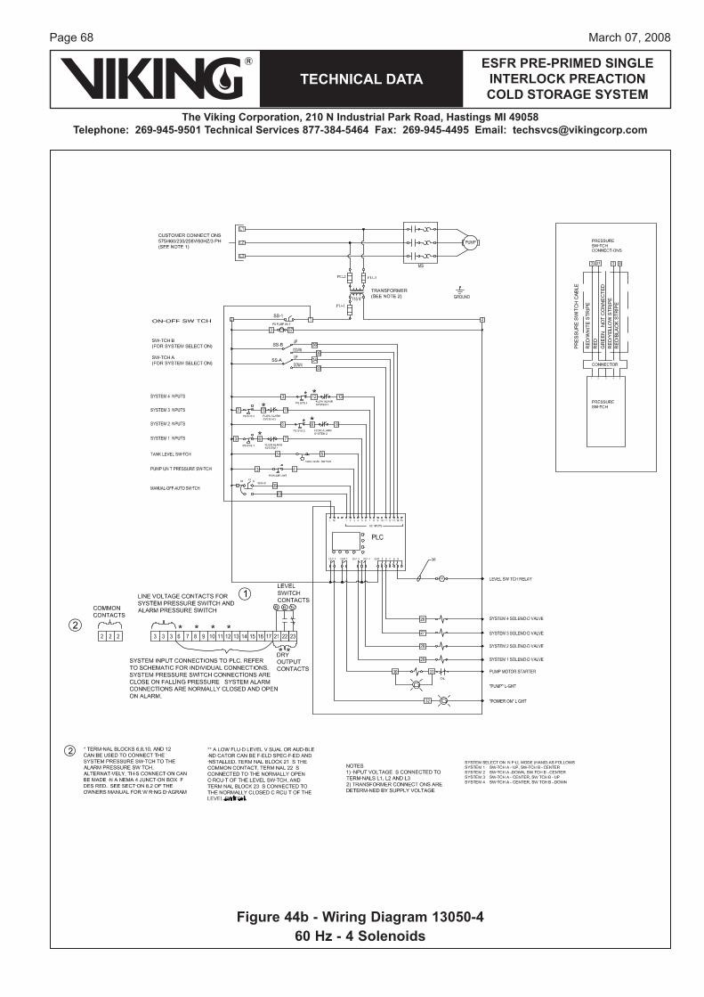
Page 68
TECHNICAL DATA
The Viking Corporation, 210 N Industrial Park Road, Hastings MI 49058Telephone: 269-945-9501 Technical Services 877-384-5464 Fax: 269-945-4495 Email: [email protected]
ESFR PRE-PRIMED SINGLE INTERLOCK PREACTION COLD STORAGE SYSTEM
March 07, 2008
Figure 44b - Wiring Diagram 13050-460 Hz - 4 Solenoids
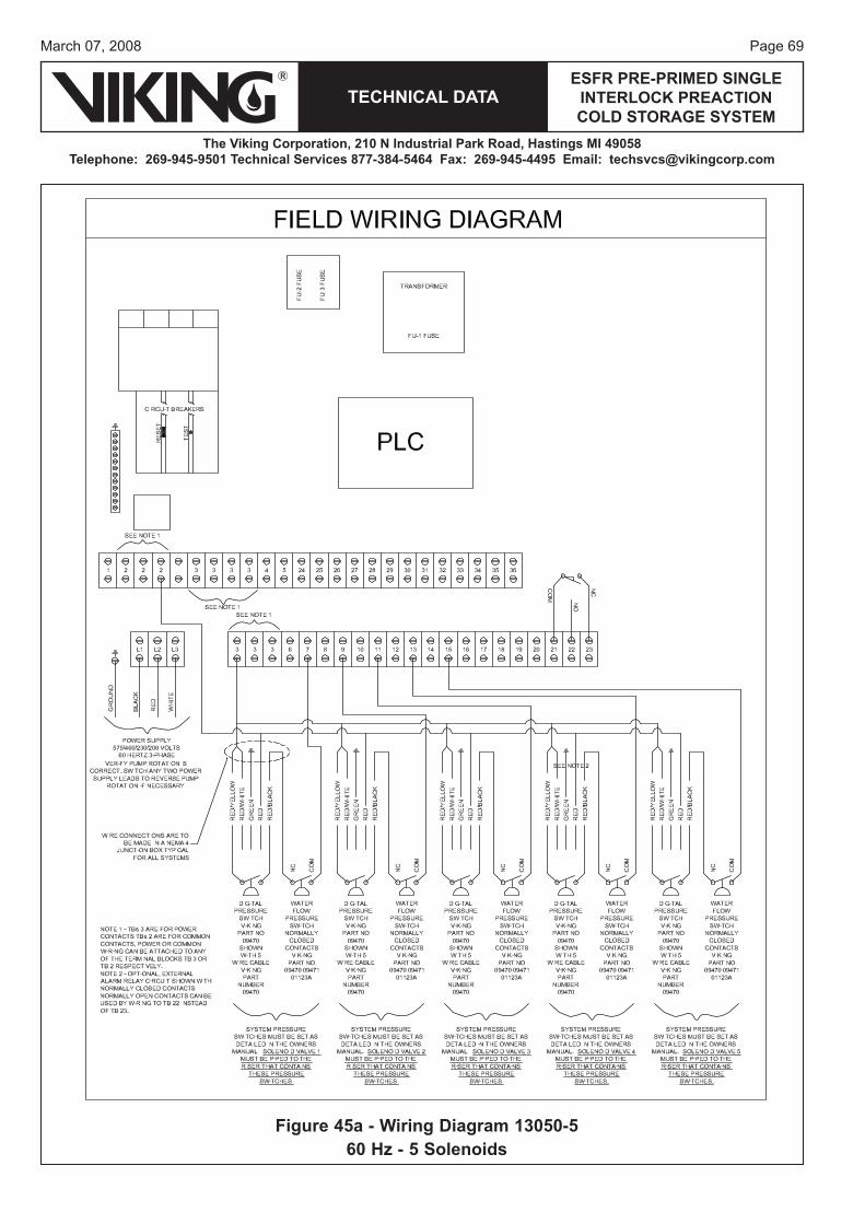
Page 69March 07, 2008
TECHNICAL DATAESFR PRE-PRIMED SINGLE
INTERLOCK PREACTION COLD STORAGE SYSTEM
The Viking Corporation, 210 N Industrial Park Road, Hastings MI 49058Telephone: 269-945-9501 Technical Services 877-384-5464 Fax: 269-945-4495 Email: [email protected]
Figure 45a - Wiring Diagram 13050-560 Hz - 5 Solenoids
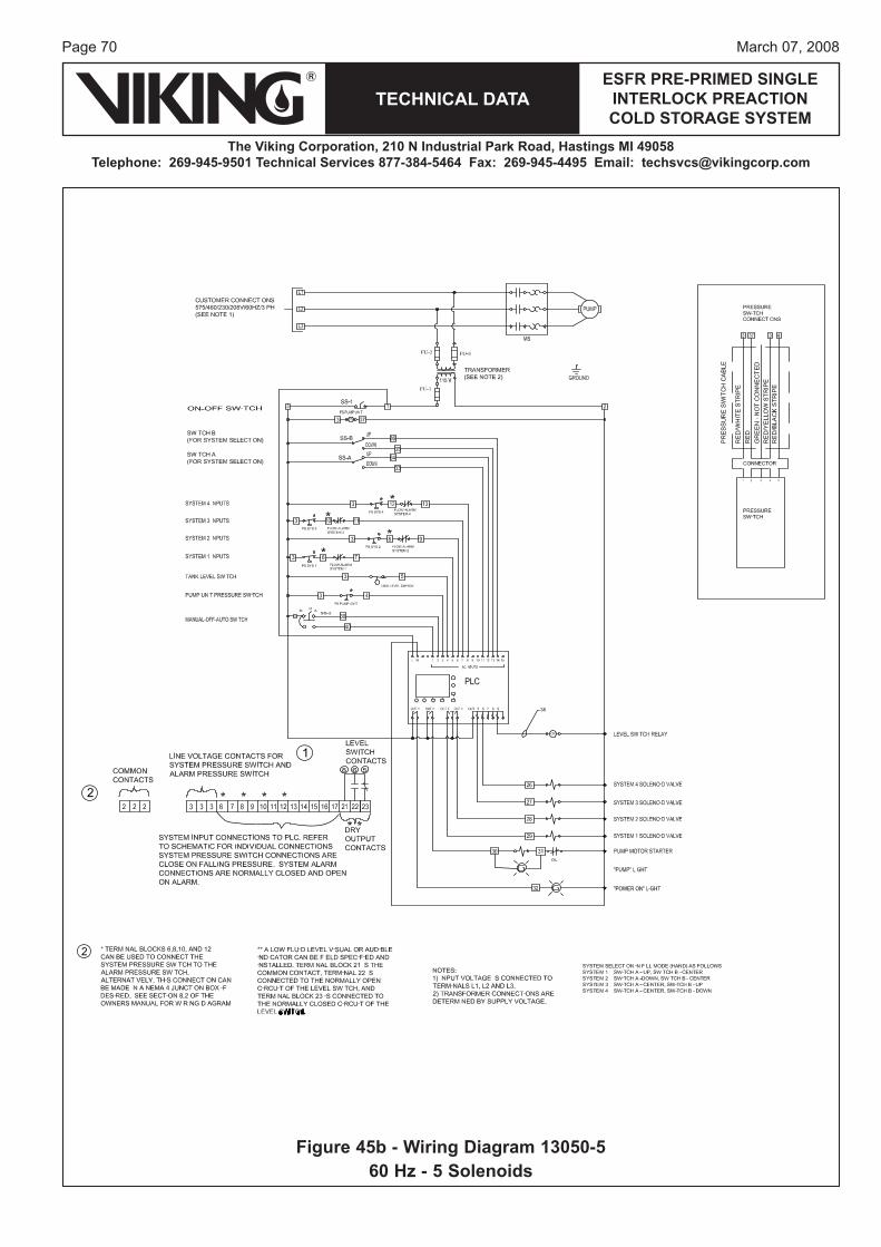
Page 70
TECHNICAL DATA
The Viking Corporation, 210 N Industrial Park Road, Hastings MI 49058Telephone: 269-945-9501 Technical Services 877-384-5464 Fax: 269-945-4495 Email: [email protected]
ESFR PRE-PRIMED SINGLE INTERLOCK PREACTION COLD STORAGE SYSTEM
March 07, 2008
Figure 45b - Wiring Diagram 13050-560 Hz - 5 Solenoids
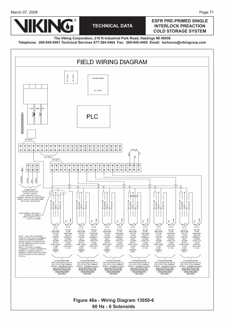
Page 71March 07, 2008
TECHNICAL DATAESFR PRE-PRIMED SINGLE
INTERLOCK PREACTION COLD STORAGE SYSTEM
The Viking Corporation, 210 N Industrial Park Road, Hastings MI 49058Telephone: 269-945-9501 Technical Services 877-384-5464 Fax: 269-945-4495 Email: [email protected]
Figure 46a - Wiring Diagram 13050-660 Hz - 6 Solenoids
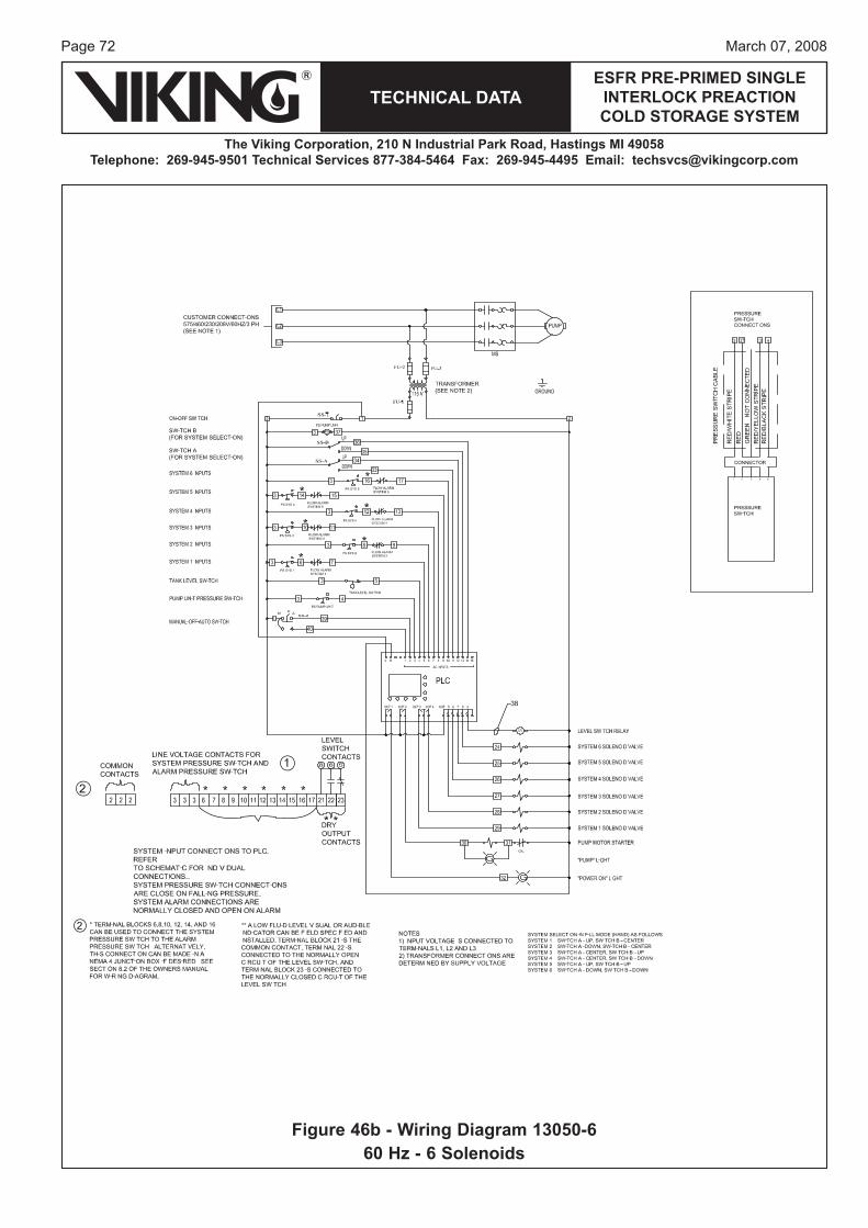
Page 72
TECHNICAL DATA
The Viking Corporation, 210 N Industrial Park Road, Hastings MI 49058Telephone: 269-945-9501 Technical Services 877-384-5464 Fax: 269-945-4495 Email: [email protected]
ESFR PRE-PRIMED SINGLE INTERLOCK PREACTION COLD STORAGE SYSTEM
March 07, 2008
Figure 46b - Wiring Diagram 13050-660 Hz - 6 Solenoids
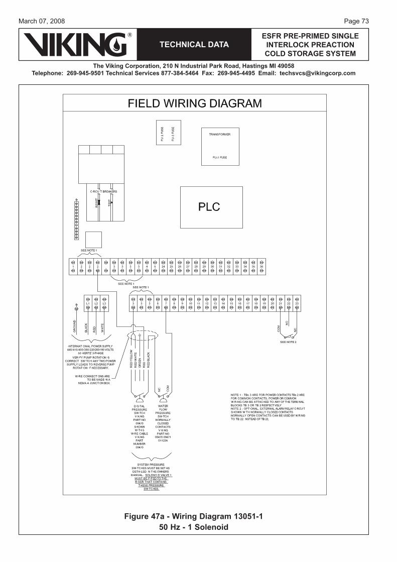
Page 73March 07, 2008
TECHNICAL DATAESFR PRE-PRIMED SINGLE
INTERLOCK PREACTION COLD STORAGE SYSTEM
The Viking Corporation, 210 N Industrial Park Road, Hastings MI 49058Telephone: 269-945-9501 Technical Services 877-384-5464 Fax: 269-945-4495 Email: [email protected]
Figure 47a - Wiring Diagram 13051-150 Hz - 1 Solenoid
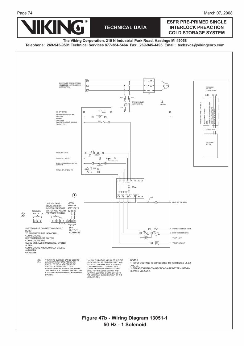
Page 74
TECHNICAL DATA
The Viking Corporation, 210 N Industrial Park Road, Hastings MI 49058Telephone: 269-945-9501 Technical Services 877-384-5464 Fax: 269-945-4495 Email: [email protected]
ESFR PRE-PRIMED SINGLE INTERLOCK PREACTION COLD STORAGE SYSTEM
March 07, 2008
Figure 47b - Wiring Diagram 13051-150 Hz - 1 Solenoid
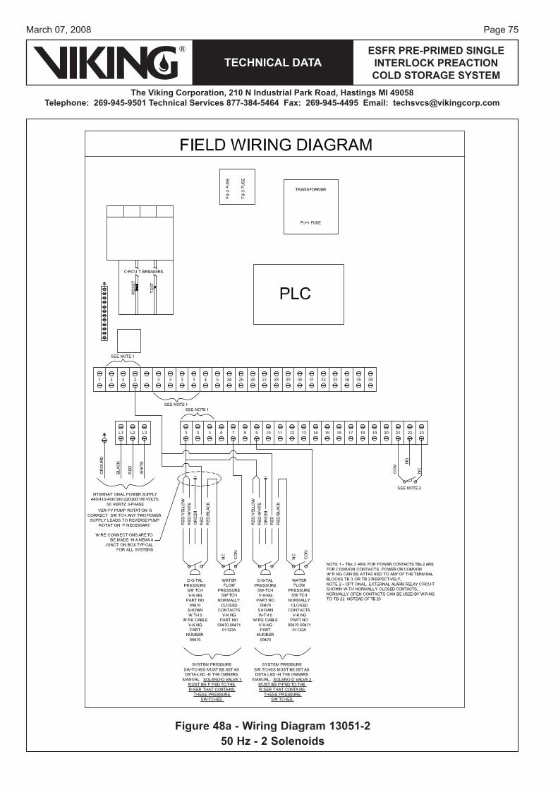
Page 75March 07, 2008
TECHNICAL DATAESFR PRE-PRIMED SINGLE
INTERLOCK PREACTION COLD STORAGE SYSTEM
The Viking Corporation, 210 N Industrial Park Road, Hastings MI 49058Telephone: 269-945-9501 Technical Services 877-384-5464 Fax: 269-945-4495 Email: [email protected]
Figure 48a - Wiring Diagram 13051-250 Hz - 2 Solenoids
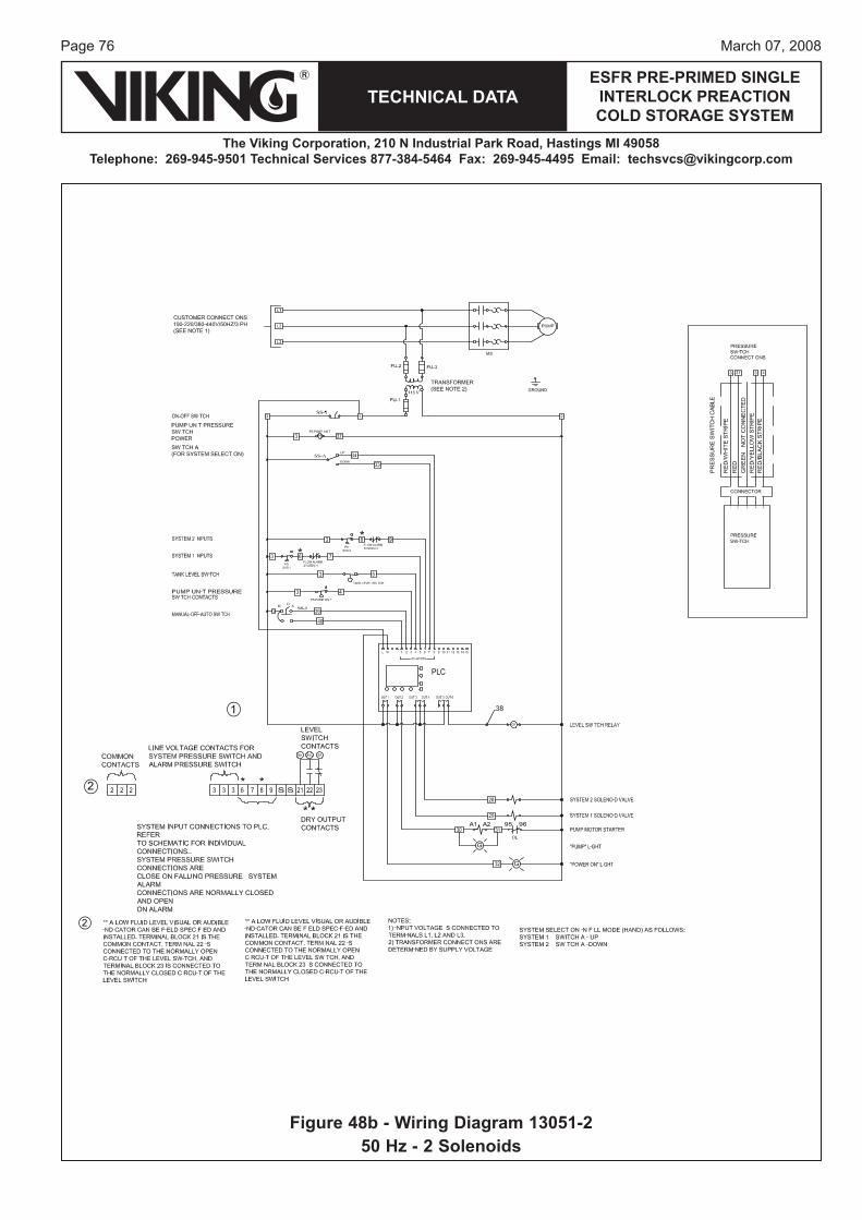
Page 76
TECHNICAL DATA
The Viking Corporation, 210 N Industrial Park Road, Hastings MI 49058Telephone: 269-945-9501 Technical Services 877-384-5464 Fax: 269-945-4495 Email: [email protected]
ESFR PRE-PRIMED SINGLE INTERLOCK PREACTION COLD STORAGE SYSTEM
March 07, 2008
Figure 48b - Wiring Diagram 13051-250 Hz - 2 Solenoids

Page 77March 07, 2008
TECHNICAL DATAESFR PRE-PRIMED SINGLE
INTERLOCK PREACTION COLD STORAGE SYSTEM
The Viking Corporation, 210 N Industrial Park Road, Hastings MI 49058Telephone: 269-945-9501 Technical Services 877-384-5464 Fax: 269-945-4495 Email: [email protected]
Figure 49a - Wiring Diagram 13051-350 Hz - 3 Solenoids
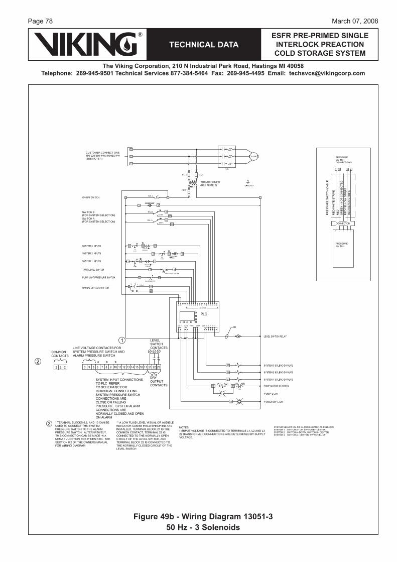
Page 78
TECHNICAL DATA
The Viking Corporation, 210 N Industrial Park Road, Hastings MI 49058Telephone: 269-945-9501 Technical Services 877-384-5464 Fax: 269-945-4495 Email: [email protected]
ESFR PRE-PRIMED SINGLE INTERLOCK PREACTION COLD STORAGE SYSTEM
March 07, 2008
Figure 49b - Wiring Diagram 13051-350 Hz - 3 Solenoids
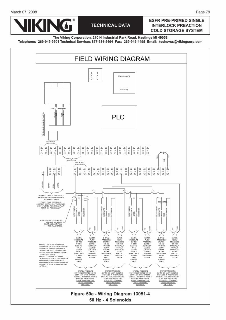
Page 79March 07, 2008
TECHNICAL DATAESFR PRE-PRIMED SINGLE
INTERLOCK PREACTION COLD STORAGE SYSTEM
The Viking Corporation, 210 N Industrial Park Road, Hastings MI 49058Telephone: 269-945-9501 Technical Services 877-384-5464 Fax: 269-945-4495 Email: [email protected]
Figure 50a - Wiring Diagram 13051-450 Hz - 4 Solenoids
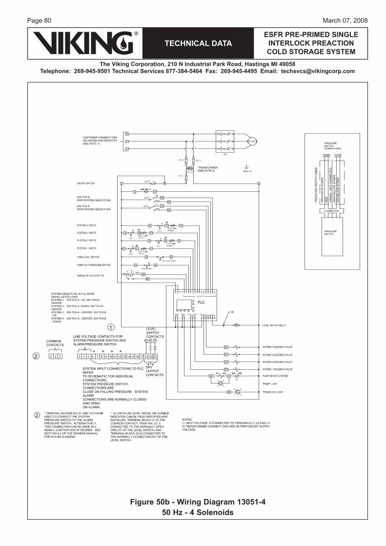
Page 80
TECHNICAL DATA
The Viking Corporation, 210 N Industrial Park Road, Hastings MI 49058Telephone: 269-945-9501 Technical Services 877-384-5464 Fax: 269-945-4495 Email: [email protected]
ESFR PRE-PRIMED SINGLE INTERLOCK PREACTION COLD STORAGE SYSTEM
March 07, 2008
Figure 50b - Wiring Diagram 13051-450 Hz - 4 Solenoids

Page 81March 07, 2008
TECHNICAL DATAESFR PRE-PRIMED SINGLE
INTERLOCK PREACTION COLD STORAGE SYSTEM
The Viking Corporation, 210 N Industrial Park Road, Hastings MI 49058Telephone: 269-945-9501 Technical Services 877-384-5464 Fax: 269-945-4495 Email: [email protected]
Figure 51a - Wiring Diagram 13051-550 Hz - 5 Solenoids
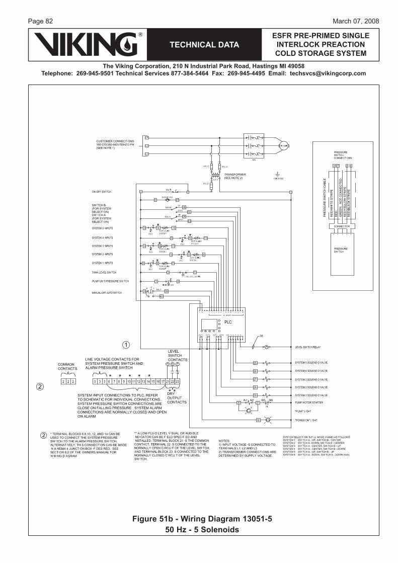
Page 82
TECHNICAL DATA
The Viking Corporation, 210 N Industrial Park Road, Hastings MI 49058Telephone: 269-945-9501 Technical Services 877-384-5464 Fax: 269-945-4495 Email: [email protected]
ESFR PRE-PRIMED SINGLE INTERLOCK PREACTION COLD STORAGE SYSTEM
March 07, 2008
Figure 51b - Wiring Diagram 13051-550 Hz - 5 Solenoids
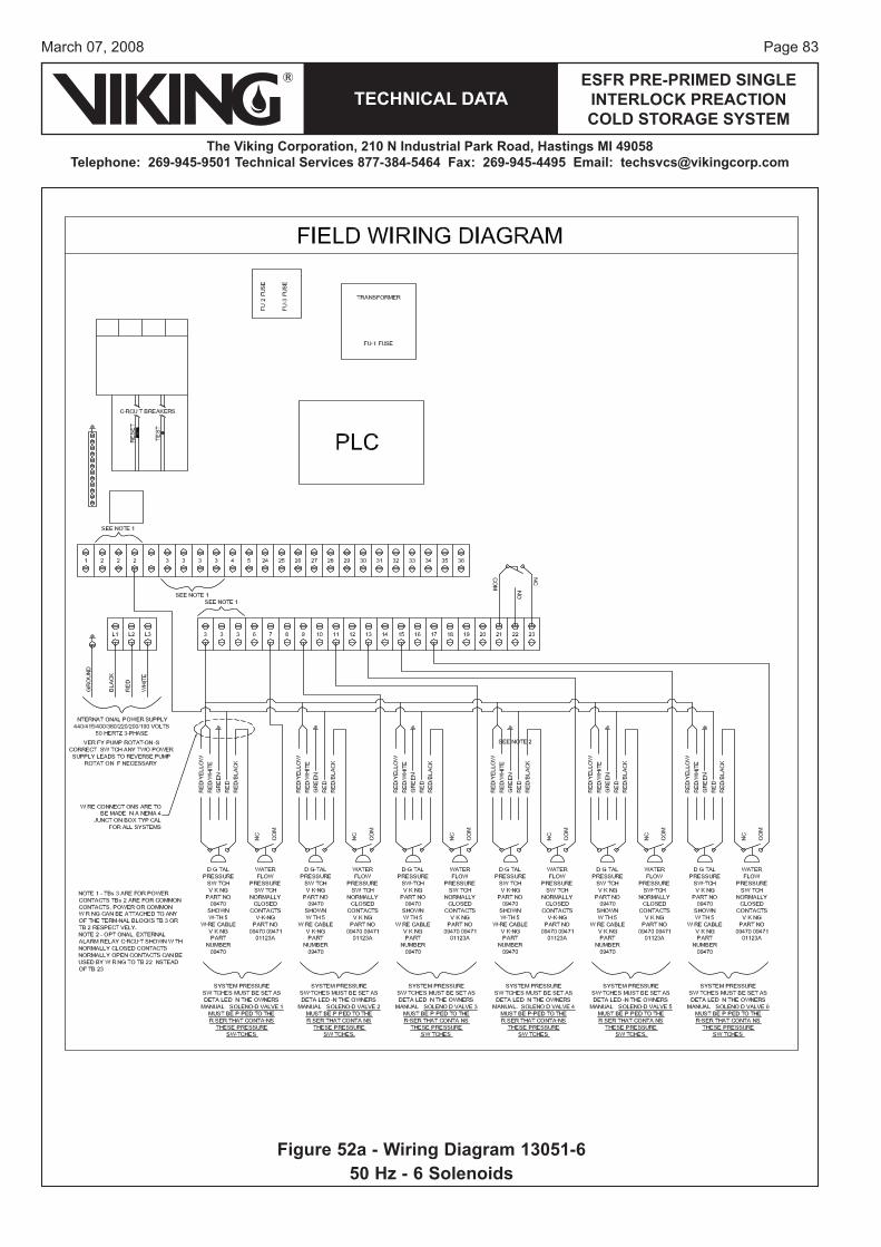
Page 83March 07, 2008
TECHNICAL DATAESFR PRE-PRIMED SINGLE
INTERLOCK PREACTION COLD STORAGE SYSTEM
The Viking Corporation, 210 N Industrial Park Road, Hastings MI 49058Telephone: 269-945-9501 Technical Services 877-384-5464 Fax: 269-945-4495 Email: [email protected]
Figure 52a - Wiring Diagram 13051-650 Hz - 6 Solenoids
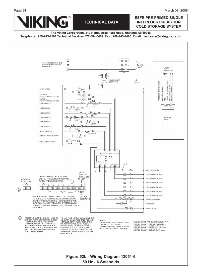
Page 84
TECHNICAL DATA
The Viking Corporation, 210 N Industrial Park Road, Hastings MI 49058Telephone: 269-945-9501 Technical Services 877-384-5464 Fax: 269-945-4495 Email: [email protected]
ESFR PRE-PRIMED SINGLE INTERLOCK PREACTION COLD STORAGE SYSTEM
March 07, 2008
Figure 52b - Wiring Diagram 13051-650 Hz - 6 Solenoids
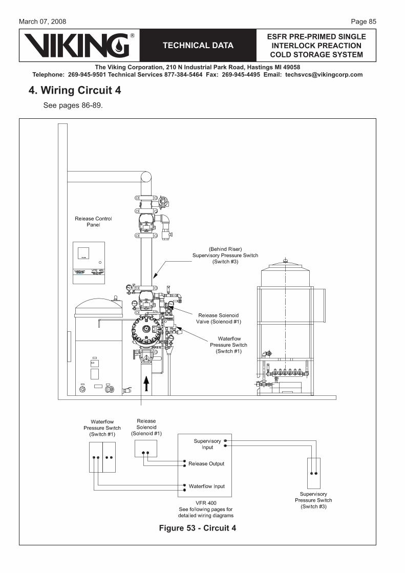
Page 85March 07, 2008
TECHNICAL DATAESFR PRE-PRIMED SINGLE
INTERLOCK PREACTION COLD STORAGE SYSTEM
The Viking Corporation, 210 N Industrial Park Road, Hastings MI 49058Telephone: 269-945-9501 Technical Services 877-384-5464 Fax: 269-945-4495 Email: [email protected]
4. Wiring Circuit 4See pages 86-89.
Figure 53 - Circuit 4
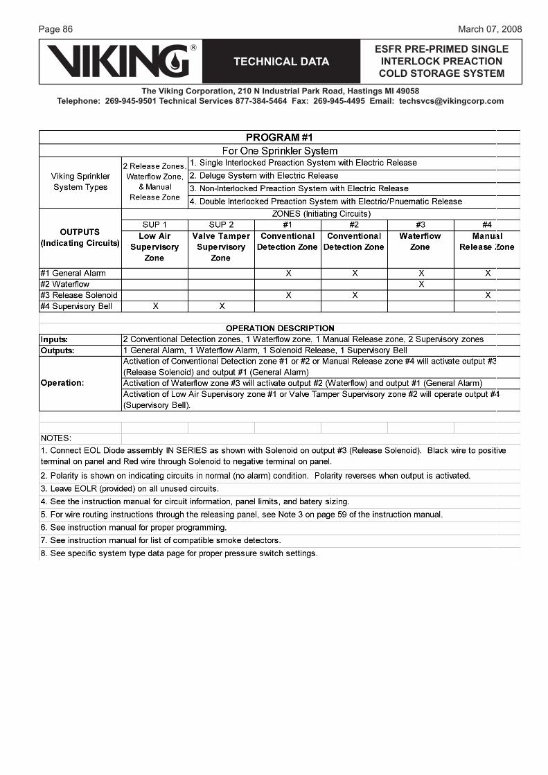
Page 86
TECHNICAL DATA
The Viking Corporation, 210 N Industrial Park Road, Hastings MI 49058Telephone: 269-945-9501 Technical Services 877-384-5464 Fax: 269-945-4495 Email: [email protected]
ESFR PRE-PRIMED SINGLE INTERLOCK PREACTION COLD STORAGE SYSTEM
March 07, 2008
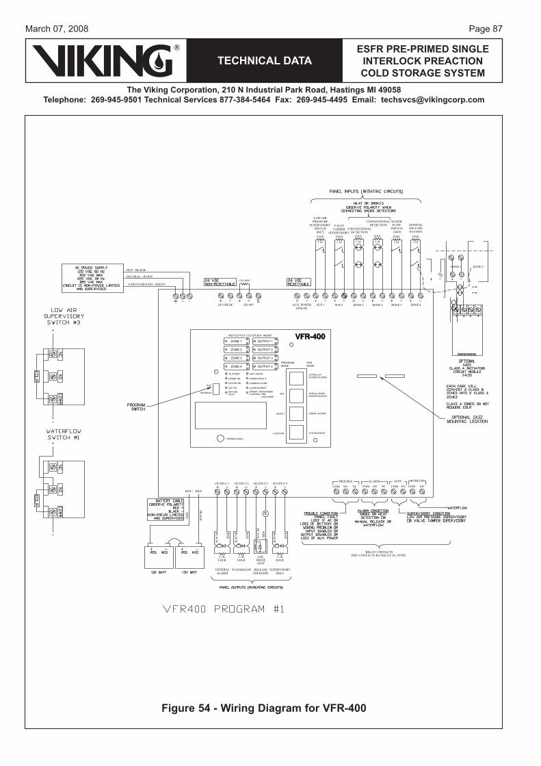
Page 87March 07, 2008
TECHNICAL DATAESFR PRE-PRIMED SINGLE
INTERLOCK PREACTION COLD STORAGE SYSTEM
The Viking Corporation, 210 N Industrial Park Road, Hastings MI 49058Telephone: 269-945-9501 Technical Services 877-384-5464 Fax: 269-945-4495 Email: [email protected]
N L
HOT - BLACK
NEUTRAL - WHITE
EARTH GROUND - GREEN
OUTPUT 1
BAT+
ASSYDIODEEOL
RED
BLACK
NOCOMNCNC NONONO COMCOMCOM
BLACK
RED
5.1KEOLR
BLACK
RED
EOLR5.1K
BLACK
RED
RELEASEALARMGENERAL
SOLENOID
ZONE 4
RELEASESTATION
WATERFLOW
ZONE 3
SWITCH
ZONE 2ZONE 1
DETECTIONCONVENTIONAL
SUP 2SUP 1
DRY CONTACTS RATED AT 3A, 30VDC
VPUSELBUORT
RELAY CONTACTS
ALARM
EOLR
5.1K
SUPERVISORYBELL
WATERFLOW
AUX. POWERRS-48524 VNR DC
120 OHM
VALVETAMPER
SUPERVISORY
LOW AIRPRESSURE
SUPERVISORYSWITCH09472
24VR DC
WTRFLW
09470
ZONE 1
ZONE 2
ZONE 3
ZONE 4
OUTPUT 1
OUTPUT 2
OUTPUT 3
OUTPUT 4PROGRAMMODE
RUNMODE
AC POWER
POWER TBL
SYSTEM TBL
SUP TBL
GROUNDFAULT
SUP 1/ABORT
SUPERVISORY 2
COMMON ALARM
ALARM SILENCE
STEADY: DISCHARGEDFLASHING: PRE- DISCHARGE
RUN
PROGRAM SET
SELECT
FUNCTION
SCROLL-DOWNBUZZER SILENCE
SIGNAL SILENCE
SYSTEM RESET
SCROLL-UPBUZZER SILENCE
VIEWING ANGLE
RED OUTPUT LED STEADY: ABORT VFR-400
EOLR
5.1K
EOLR
5.1K
EOLR
5.1K
EOLR
5.1K
BAT-
OUTPUT 2 OUTPUT 3 OUTPUT 4
MANUAL
ZONE 1
DETECTIONCONVENTIONAL
ZONE 2
EOLR5.1K
BLACK
RED
EOLR
5.1K
Figure 54 - Wiring Diagram for VFR-400
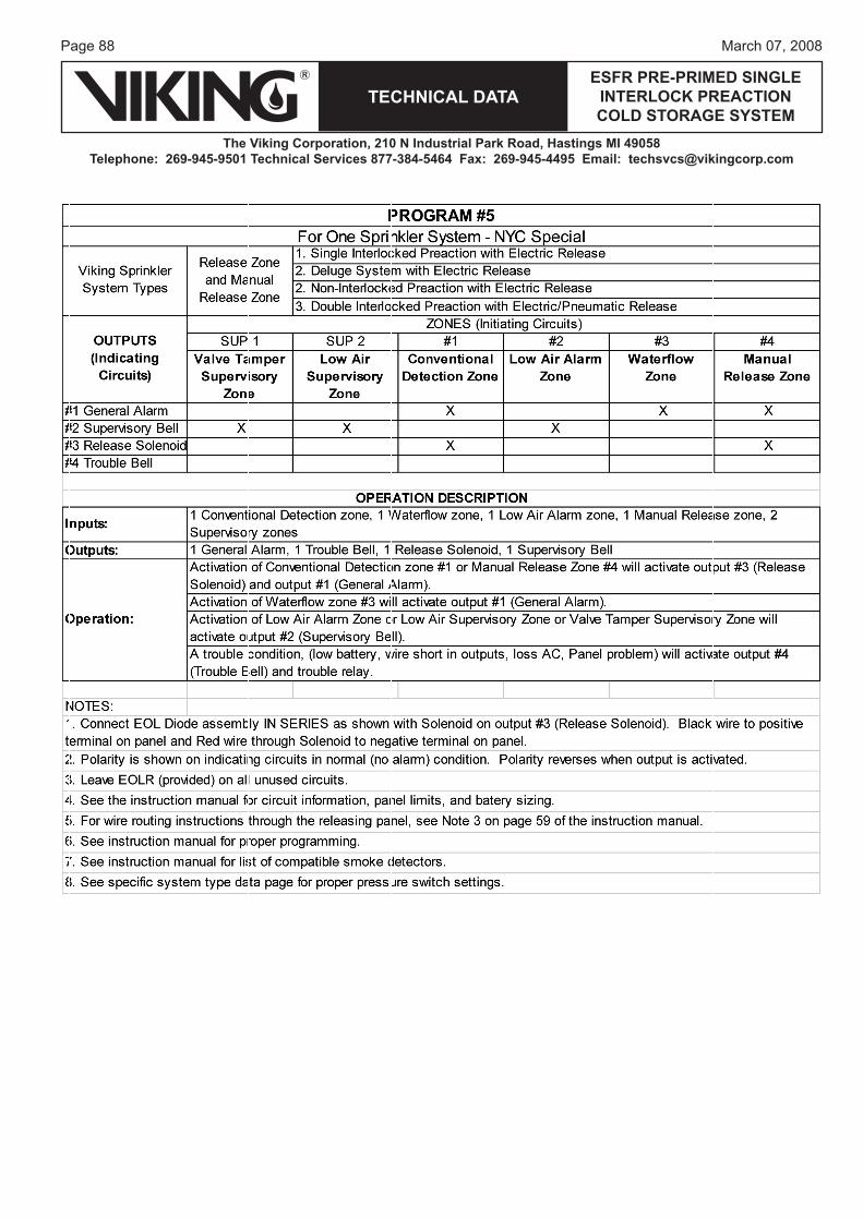
Page 88
TECHNICAL DATA
The Viking Corporation, 210 N Industrial Park Road, Hastings MI 49058Telephone: 269-945-9501 Technical Services 877-384-5464 Fax: 269-945-4495 Email: [email protected]
ESFR PRE-PRIMED SINGLE INTERLOCK PREACTION COLD STORAGE SYSTEM
March 07, 2008
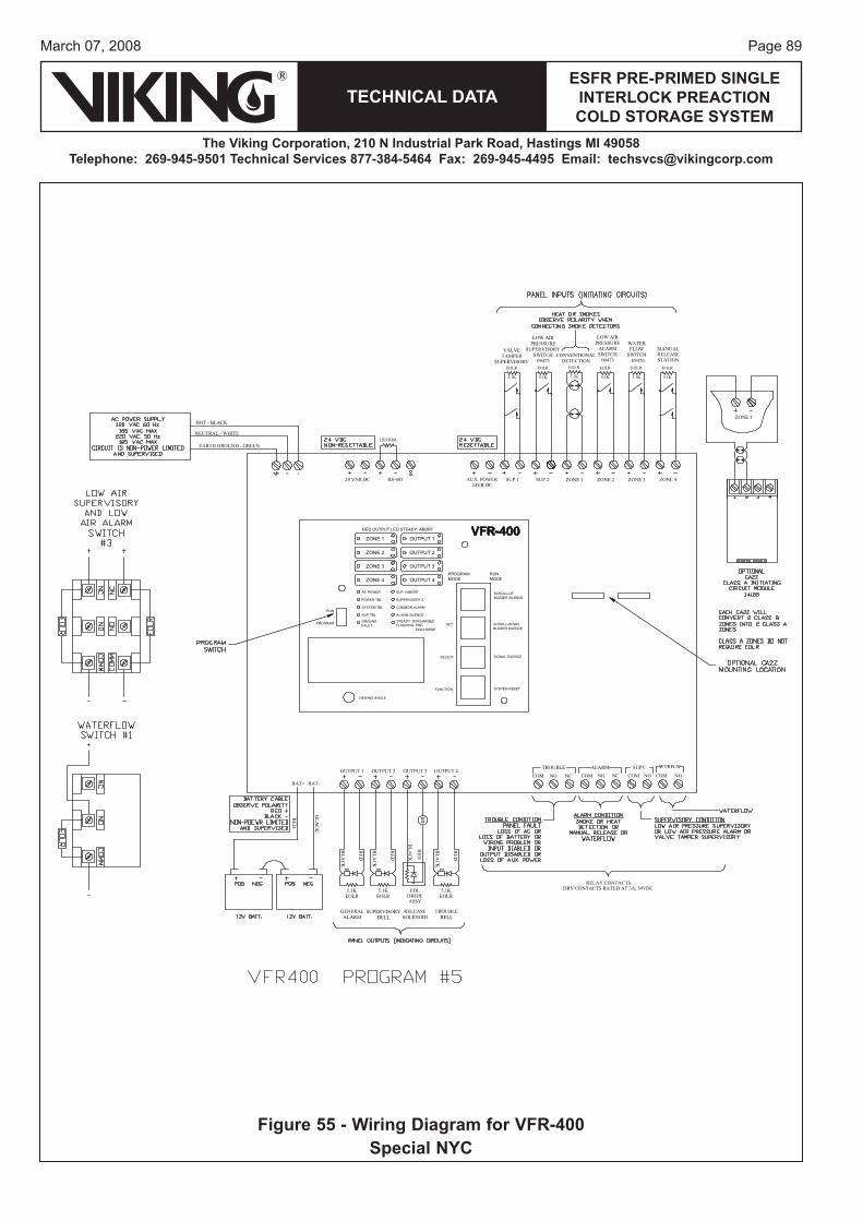
Page 89March 07, 2008
TECHNICAL DATAESFR PRE-PRIMED SINGLE
INTERLOCK PREACTION COLD STORAGE SYSTEM
The Viking Corporation, 210 N Industrial Park Road, Hastings MI 49058Telephone: 269-945-9501 Technical Services 877-384-5464 Fax: 269-945-4495 Email: [email protected]
N L
HOT - BLACK
NEUTRAL - WHITE
EARTH GROUND - GREEN
OUTPUT 1
BAT+
ASSYDIODEEOL
RED
BLACK
NOCOMNCNC NONONO COMCOMCOM
BLACK
RED
5.1KEOLR
BLACK
RED
EOLR5.1K
BLACK
RED
RELEASEALARMGENERAL
SOLENOID
ZONE 4
RELEASESTATION
WATERFLOW
ZONE 3
SWITCH
ZONE 2ZONE 1
DETECTIONCONVENTIONAL
SUP 2SUP 1
DRY CONTACTS RATED AT 3A, 30VDC
VPUSELBUORT
RELAY CONTACTS
ALARM
EOLR
5.1K
TROUBLEBELL
SUPERVISORYBELL
AUX. POWERRS-48524 VNR DC
120 OHM
VALVETAMPER
SUPERVISORY
LOW AIRPRESSURE
SUPERVISORYSWITCH09473
LOW AIRPRESSUREALARMSWITCH09473
24VR DC
WTRFLW
09470
ZONE 1
ZONE 2
ZONE 3
ZONE 4
OUTPUT 1
OUTPUT 2
OUTPUT 3
OUTPUT 4PROGRAMMODE
RUNMODE
AC POWER
POWER TBL
SYSTEM TBL
SUP TBL
GROUNDFAULT
SUP 1/ABORT
SUPERVISORY 2
COMMON ALARM
ALARM SILENCE
STEADY: DISCHARGEDFLASHING: PRE- DISCHARGE
RUN
PROGRAM SET
SELECT
FUNCTION
SCROLL-DOWNBUZZER SILENCE
SIGNAL SILENCE
SYSTEM RESET
SCROLL-UPBUZZER SILENCE
VIEWING ANGLE
RED OUTPUT LED STEADY: ABORT VFR-400
EOLR
5.1K
EOLR
5.1K
EOLR
5.1K
EOLR
5.1K
EOLR
5.1K
BAT-
OUTPUT 2 OUTPUT 3 OUTPUT 4
MANUAL
ZONE 1
EOLR5.1K
BLACK
RED
Figure 55 - Wiring Diagram for VFR-400Special NYC
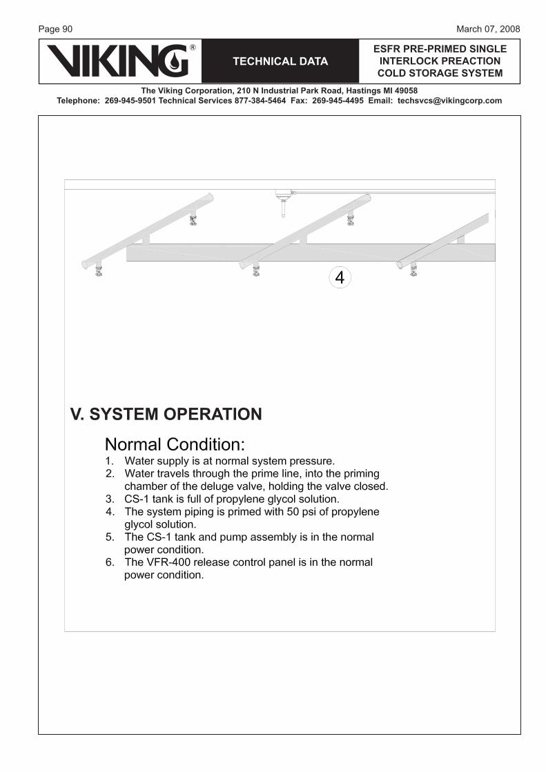
Page 90
TECHNICAL DATA
The Viking Corporation, 210 N Industrial Park Road, Hastings MI 49058Telephone: 269-945-9501 Technical Services 877-384-5464 Fax: 269-945-4495 Email: [email protected]
ESFR PRE-PRIMED SINGLE INTERLOCK PREACTION COLD STORAGE SYSTEM
March 07, 2008
V. SYSTEM OPERATION

Page 91March 07, 2008
TECHNICAL DATAESFR PRE-PRIMED SINGLE
INTERLOCK PREACTION COLD STORAGE SYSTEM
The Viking Corporation, 210 N Industrial Park Road, Hastings MI 49058Telephone: 269-945-9501 Technical Services 877-384-5464 Fax: 269-945-4495 Email: [email protected]
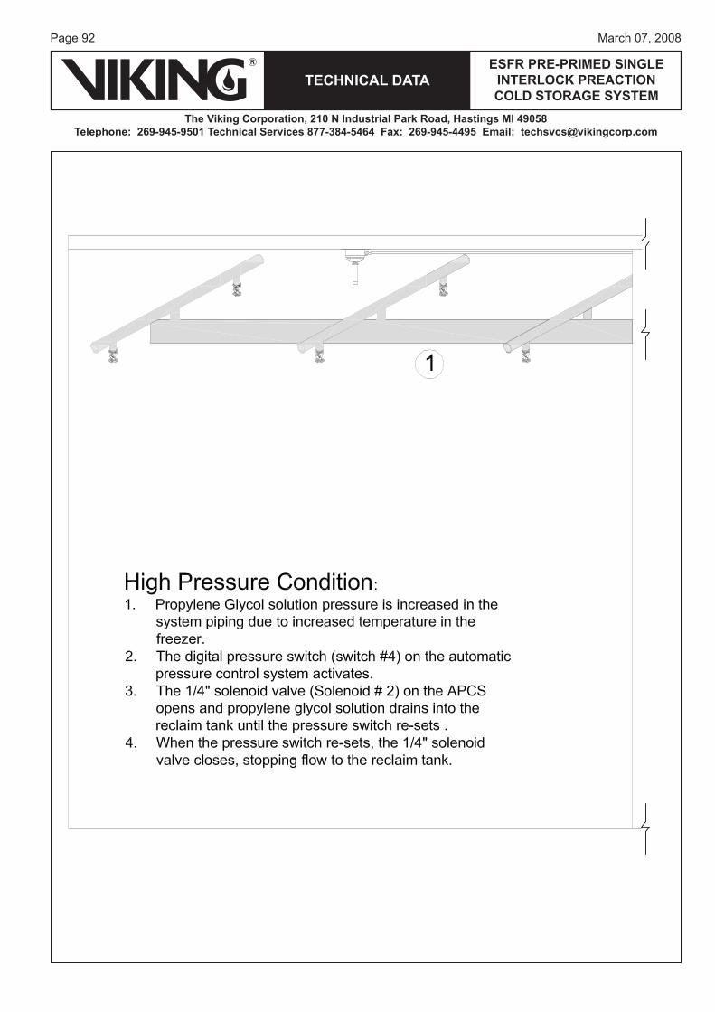
Page 92
TECHNICAL DATA
The Viking Corporation, 210 N Industrial Park Road, Hastings MI 49058Telephone: 269-945-9501 Technical Services 877-384-5464 Fax: 269-945-4495 Email: [email protected]
ESFR PRE-PRIMED SINGLE INTERLOCK PREACTION COLD STORAGE SYSTEM
March 07, 2008
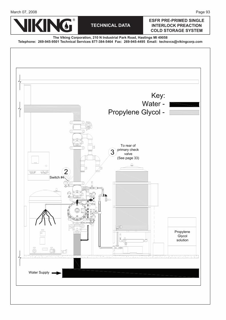
Page 93March 07, 2008
TECHNICAL DATAESFR PRE-PRIMED SINGLE
INTERLOCK PREACTION COLD STORAGE SYSTEM
The Viking Corporation, 210 N Industrial Park Road, Hastings MI 49058Telephone: 269-945-9501 Technical Services 877-384-5464 Fax: 269-945-4495 Email: [email protected]
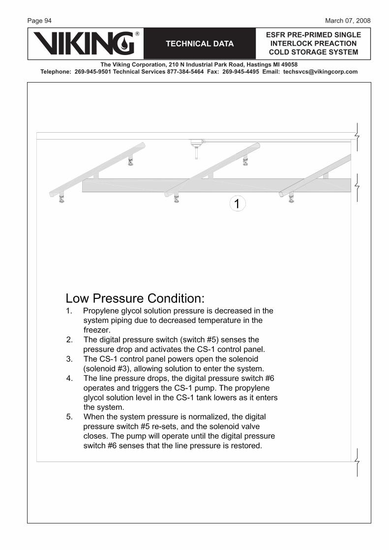
Page 94
TECHNICAL DATA
The Viking Corporation, 210 N Industrial Park Road, Hastings MI 49058Telephone: 269-945-9501 Technical Services 877-384-5464 Fax: 269-945-4495 Email: [email protected]
ESFR PRE-PRIMED SINGLE INTERLOCK PREACTION COLD STORAGE SYSTEM
March 07, 2008
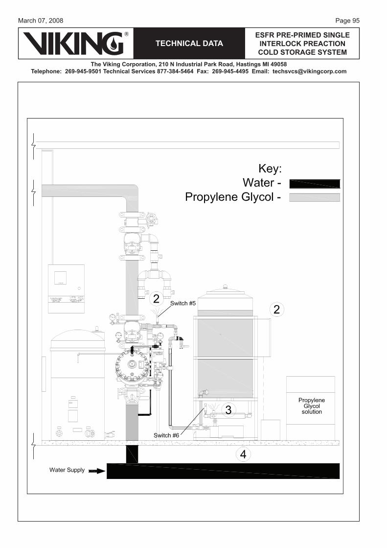
Page 95March 07, 2008
TECHNICAL DATAESFR PRE-PRIMED SINGLE
INTERLOCK PREACTION COLD STORAGE SYSTEM
The Viking Corporation, 210 N Industrial Park Road, Hastings MI 49058Telephone: 269-945-9501 Technical Services 877-384-5464 Fax: 269-945-4495 Email: [email protected]
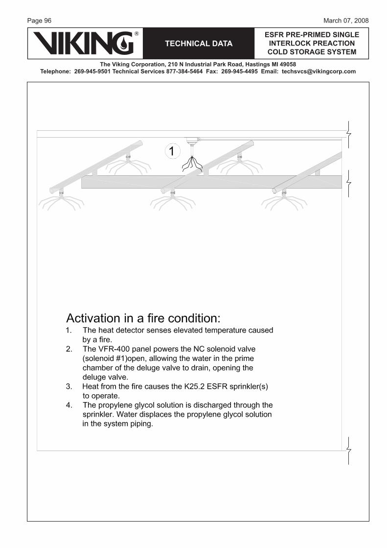
Page 96
TECHNICAL DATA
The Viking Corporation, 210 N Industrial Park Road, Hastings MI 49058Telephone: 269-945-9501 Technical Services 877-384-5464 Fax: 269-945-4495 Email: [email protected]
ESFR PRE-PRIMED SINGLE INTERLOCK PREACTION COLD STORAGE SYSTEM
March 07, 2008
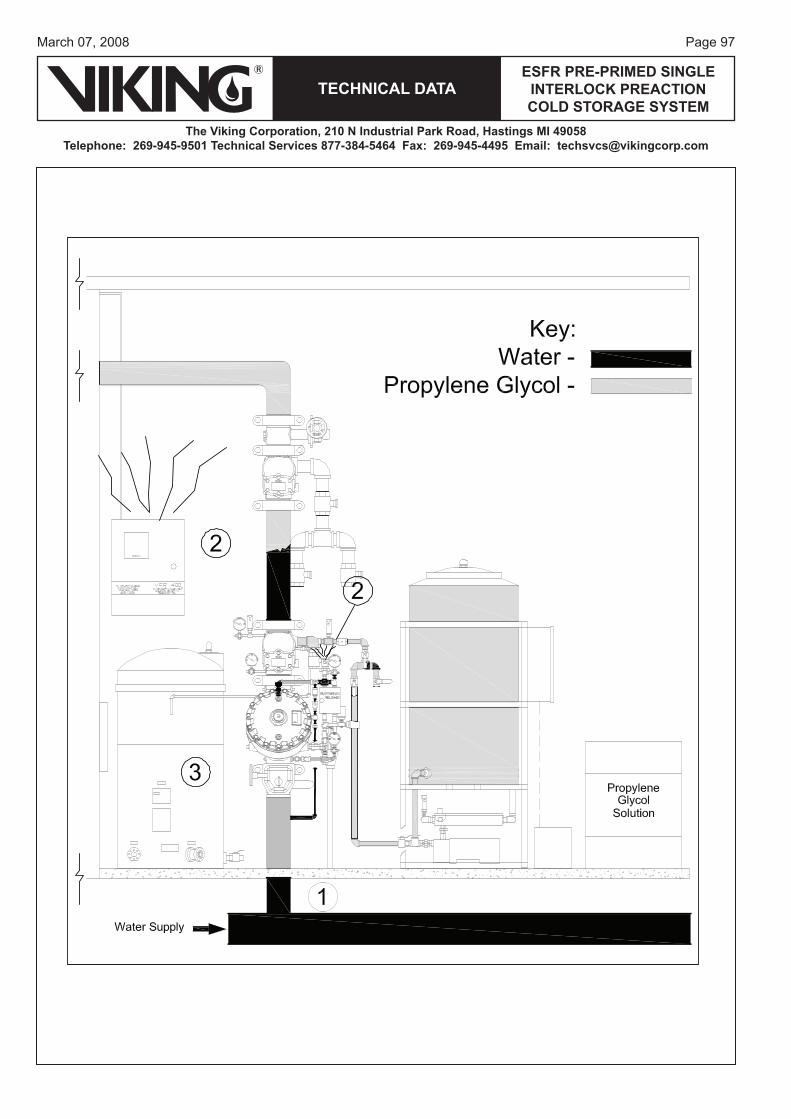
Page 97March 07, 2008
TECHNICAL DATAESFR PRE-PRIMED SINGLE
INTERLOCK PREACTION COLD STORAGE SYSTEM
The Viking Corporation, 210 N Industrial Park Road, Hastings MI 49058Telephone: 269-945-9501 Technical Services 877-384-5464 Fax: 269-945-4495 Email: [email protected]
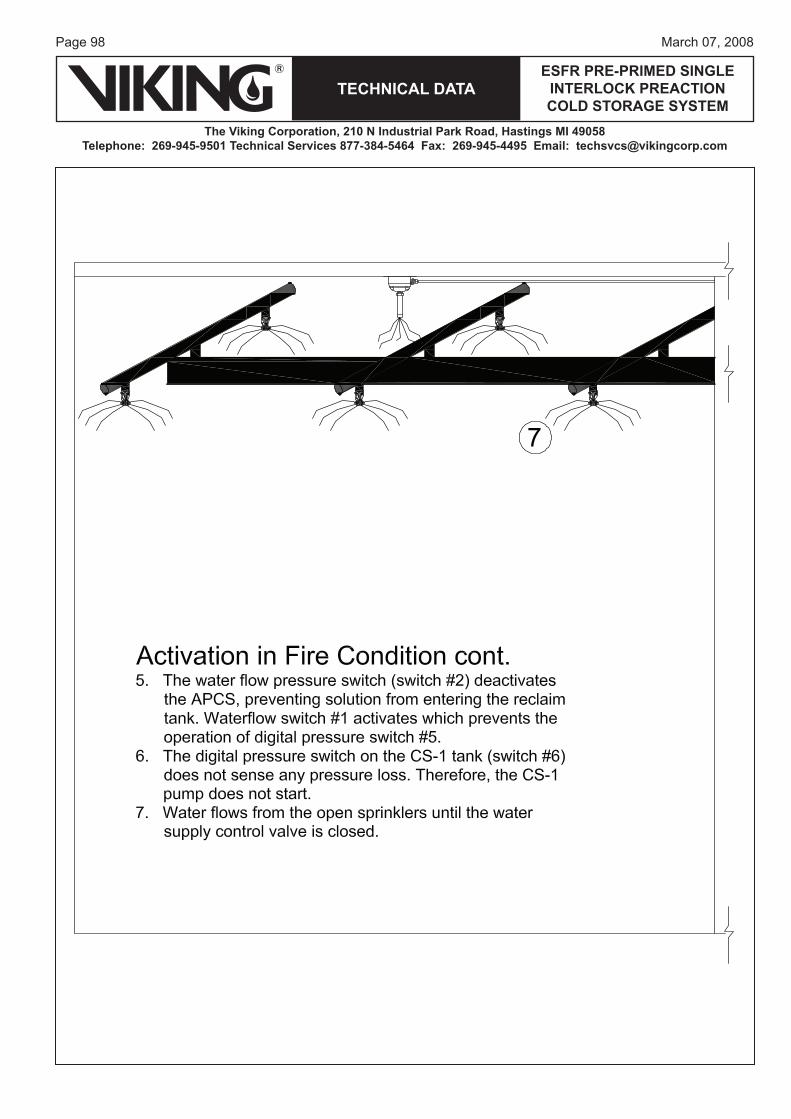
Page 98
TECHNICAL DATA
The Viking Corporation, 210 N Industrial Park Road, Hastings MI 49058Telephone: 269-945-9501 Technical Services 877-384-5464 Fax: 269-945-4495 Email: [email protected]
ESFR PRE-PRIMED SINGLE INTERLOCK PREACTION COLD STORAGE SYSTEM
March 07, 2008
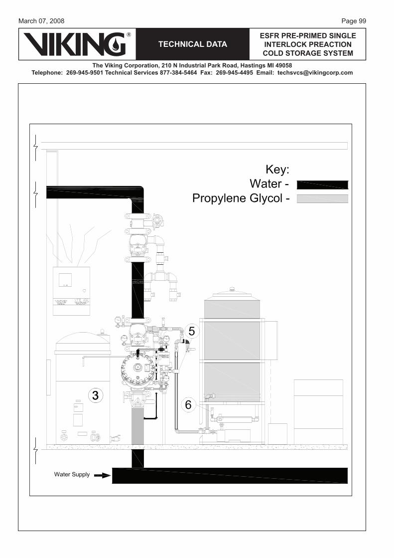
Page 99March 07, 2008
TECHNICAL DATAESFR PRE-PRIMED SINGLE
INTERLOCK PREACTION COLD STORAGE SYSTEM
The Viking Corporation, 210 N Industrial Park Road, Hastings MI 49058Telephone: 269-945-9501 Technical Services 877-384-5464 Fax: 269-945-4495 Email: [email protected]
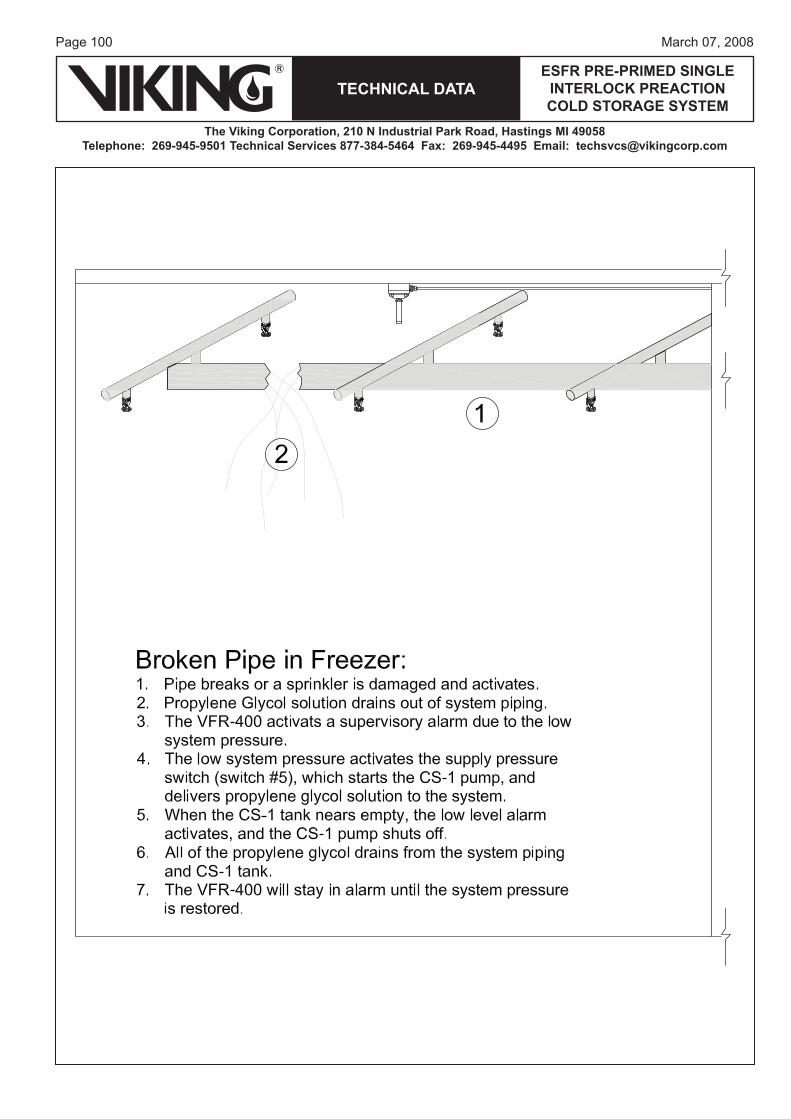
Page 100
TECHNICAL DATA
The Viking Corporation, 210 N Industrial Park Road, Hastings MI 49058Telephone: 269-945-9501 Technical Services 877-384-5464 Fax: 269-945-4495 Email: [email protected]
ESFR PRE-PRIMED SINGLE INTERLOCK PREACTION COLD STORAGE SYSTEM
March 07, 2008
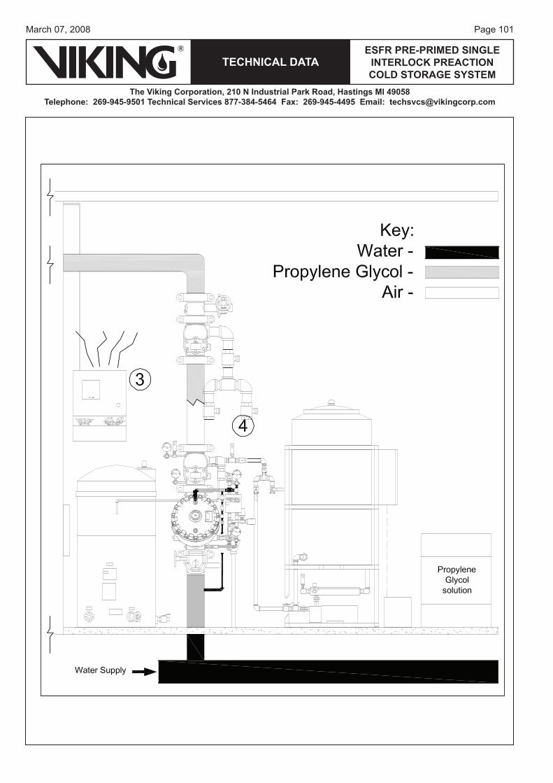
Page 101March 07, 2008
TECHNICAL DATAESFR PRE-PRIMED SINGLE
INTERLOCK PREACTION COLD STORAGE SYSTEM
The Viking Corporation, 210 N Industrial Park Road, Hastings MI 49058Telephone: 269-945-9501 Technical Services 877-384-5464 Fax: 269-945-4495 Email: [email protected]
Page 102
TECHNICAL DATA
The Viking Corporation, 210 N Industrial Park Road, Hastings MI 49058Telephone: 269-945-9501 Technical Services 877-384-5464 Fax: 269-945-4495 Email: [email protected]
ESFR PRE-PRIMED SINGLE INTERLOCK PREACTION COLD STORAGE SYSTEM
March 07, 2008
VI. SYSTEM INSPECTIONS, TESTS AND MAINTENANCE1. Solution Test Valves Multiple propylene glycol/water solution test valves are to be installed on the system piping for semi-annual testing with a refractometer to detect the concentration of antifreeze solution and effectiveness against freezing. When draining sample antifreeze solution from the system, be sure to shut off the system control valve directly upstream of the deluge valve so that water doesn’t enter the system. Sampling shall be taken from multiple points within the freezer system. The testing stated in this section is more restrictive than the required test frequency indicated in NFPA 25. Solution test valves should be located in several areas of the system piping as follows:
The most practical location immediately downstream of the primary Easy Riser® Check Valve.The most remote location from the Easy Riser® Check Valve.One valve located at the end of 50% of the line piping directly on the AV-1 Air/Vent Valve assem-bly.A test valve shall be located at the end of the nearest line on the tree system and the last line on the tree system.
If the propylene glycol/water solution becomes diluted or does not pass the refractometer test, the entire system is to be drained; all sections of trapped piping are to be drained. Five percent (5%) of the pendent ESFR sprinklers are to be removed and inspected for frozen solution. If any of the pendent ESFR sprin-klers are found with frozen solution, then all the pendent ESFR sprinklers are to be removed and replaced with new Viking K25.2 Pendent ESFR VK510 Sprinklers prior to re-charging the system with new 35% or 50% premix propylene glycol/water solution. If the 5% of removed sprinklers are not damaged, they can be re-installed in the system. (Refer to the system service schedule for additional solution tests.)Ensure that the CS-1 pump antifreeze supply control system is returned to the fully pressurized state once fluid sampling is completed. After the CS-1 pump has restored the antifreeze solution pressure, ensure that the water supply control valve is returned to the fully open position once fluid sampling is completed.
2. Alarm Test ConnectionAn alarm test connection is provided on the deluge valve trim. When testing the alarm, the downstream isolation valve and antifreeze isolation valve must be shut before opening the test valve. This is a precau-tion in case the deluge valve would inadvertently operate due to problems in the trim components and cause water to enter the system causing possible contamination of antifreeze. After testing of the alarm, restore the control valves to their normal operating position and open the antifreeze supply valve.
3. Flow Test ValveAnnual flow tests are required for every sprinkler system. When performing annual water flow tests for the ESFR Pre-Primed Single Interlocked Preaction Cold Storage System, you will utilize the main drain of the isolation check valve. This will allow the primary check valve clapper to open also. First, close the supervised system isolation valve downstream of the isolation check valve. Close the antifreeze inlet ball valve.The deluge valve must be operated (opened) to perform the flow test. Close the prime line valve and open the emergency manual release valve. Make sure the diversion drain valve is open to flow water to a drain area or the recovery tank as desired. Note: If antifreeze is stored in the recovery tank, do not allow water to enter, or contamination of solution will occur. Record the water supply pressure on the water supply pressure gauge upstream of the deluge valve.
•••
•
Page 103March 07, 2008
TECHNICAL DATAESFR PRE-PRIMED SINGLE
INTERLOCK PREACTION COLD STORAGE SYSTEM
The Viking Corporation, 210 N Industrial Park Road, Hastings MI 49058Telephone: 269-945-9501 Technical Services 877-384-5464 Fax: 269-945-4495 Email: [email protected]
Open the main drain on the downstream Isolation check valve fully. This will allow water to flow through the deluge valve and both the primary and isolation check valves. Once the pressure gauge has settled to flowing pressure, record the pressure on the water supply pressure gauge upstream of the deluge valve.After the water flow test is completed, close the water supply control valve upstream of the deluge valve, drain all the water located between the primary and isolation check valves. Then drain all water from between the deluge valve and the primary check valve using the auxiliary drain on the deluge valve trim. Close the main drain and auxiliary drain once water is completely drained. Open the antifreeze supply isolation valve. The CS-1 pump will supply propylene glycol/water solution from the maintenance solu-tion supply tank. The CS-1 pump will stop running when the pressure in the section of piping is 50 PSI (3.45 Bar) or the set pressure of the system pressure switch. Ensure there is no trapped air in the piping between check valves by bleeding through the main drain valve of the isolation check valve. After system pressure is built, the CS-1 pump will stop running. Open the down stream system isolation valve, when system antifreeze pressure is at desired pressure and the CS-1 pump stops. Now, prime the deluge valve by opening the prime supply valve and watch for pressure to build in the prime chamber of the deluge valve. Now, open the system shut-off valve up stream of the deluge valve. Any supervisory alarm switches silenced for system maintenance must be re-set. The system is now in service.
4. SERVICE PROCEDURESA. Drain-Down of the Individual System (if system operation has occurred):
1. After system trip and sprinkler(s) have operated and water has entered the system, the complete system must be drained down immediately and solution within the piping system disposed of.
2. All sprinklers are pendent type and must be removed and replaced with new sprinklers. This is due to possible collection of water at each sprinkler and creation of a small ice plug in each sprinkler.
3. If using the Viking Model AV-1 Air/vent Valve assembly the device also breaks a vacuum in the piping system and provides faster and more complete drainage of the system piping.
B. Taking the System Out of Service:1. Close the water supply control valve to the riser being serviced.2. Close the antifreeze supply valve to the riser being serviced.3. If the system is being serviced, then the solution in the system can be drained into clean con-
tainers or reclaim tank and reused as long as water has not entered the systems. Solution should be checked at various points while draining for proper refractometer readings to verify freeze-protection properties.
4. Open vent/bleed valves at high points of the system or if the AV-1 Vent Valve is applied it will automatically open.
5. Open the main drain and collect solution in clean containers or recovery tank for re-use in system.
6. After the system is completely drained from the main drain, open any low-point drains to remove the remaining solution from the system.
C. Placing the System in Service (after it has been completely drained):1. Close the main drain valve on the riser.

Page 104
TECHNICAL DATA
The Viking Corporation, 210 N Industrial Park Road, Hastings MI 49058Telephone: 269-945-9501 Technical Services 877-384-5464 Fax: 269-945-4495 Email: [email protected]
ESFR PRE-PRIMED SINGLE INTERLOCK PREACTION COLD STORAGE SYSTEM
March 07, 2008
2. Connect the propylene glycol/water solution fill pump (NOT the CS-1 pump) to the connec-tion located on the main drain assembly.
3. Close the main drain valve, vent/bleed valves, and low-point drains if opened. Ensure there are no openings on system piping.
4. Fill system with Firefighter Eliminator C or Eliminator F propylene glycol/water solution. While filling, periodically open the manual vent/bleed valves or allow the Model AV-1 Vent Valve to automatically open on system piping to ensure air is eliminated from system piping. Slow fill is recommended to minimize the entrainment of air.
5. Fill and pressurize system piping to 50 PSI (3.45 Bar) minimum using the CS-1 Pump sys-tem to provide the final set system pressure.
6. Check for trapped air by cracking open vent/bleed valves or observe the AV-1 Vent Valve. Ensure all trapped air is eliminated from the system.
7. After system pressure is attained, the water supply control valve up stream of the deluge valve can be opened.
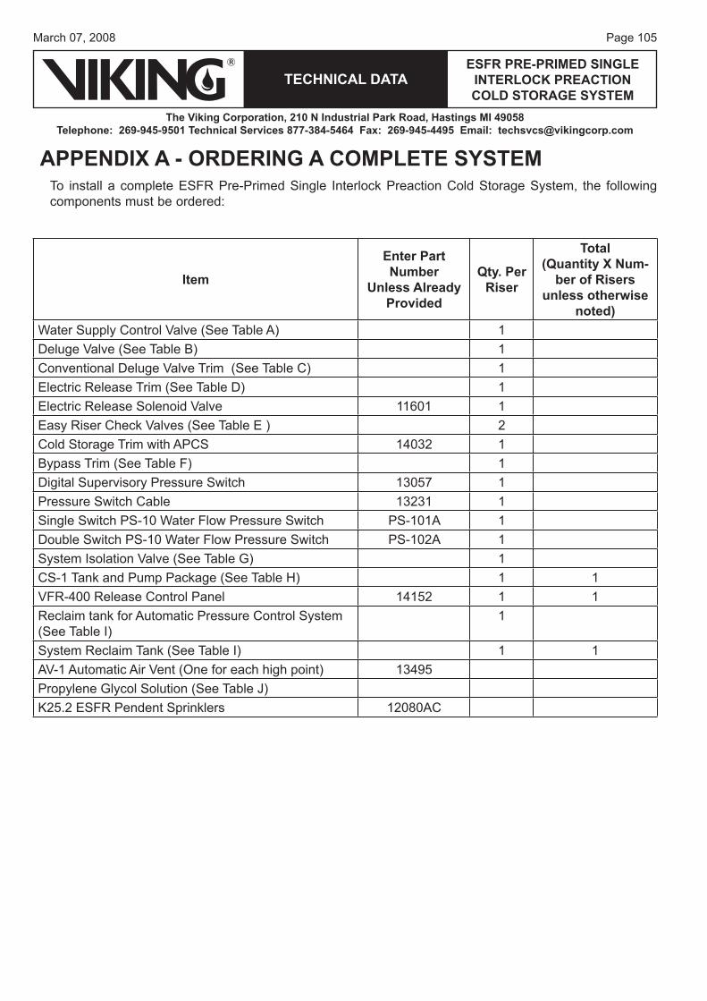
Page 105March 07, 2008
TECHNICAL DATAESFR PRE-PRIMED SINGLE
INTERLOCK PREACTION COLD STORAGE SYSTEM
The Viking Corporation, 210 N Industrial Park Road, Hastings MI 49058Telephone: 269-945-9501 Technical Services 877-384-5464 Fax: 269-945-4495 Email: [email protected]
APPENDIX A - ORDERING A COMPLETE SYSTEMTo install a complete ESFR Pre-Primed Single Interlock Preaction Cold Storage System, the following components must be ordered:
Item
Enter Part Number
Unless Already Provided
Qty. Per Riser
Total(Quantity X Num-
ber of Risers unless otherwise
noted)Water Supply Control Valve (See Table A) 1Deluge Valve (See Table B) 1Conventional Deluge Valve Trim (See Table C) 1Electric Release Trim (See Table D) 1Electric Release Solenoid Valve 11601 1Easy Riser Check Valves (See Table E ) 2Cold Storage Trim with APCS 14032 1Bypass Trim (See Table F) 1Digital Supervisory Pressure Switch 13057 1Pressure Switch Cable 13231 1Single Switch PS-10 Water Flow Pressure Switch PS-101A 1Double Switch PS-10 Water Flow Pressure Switch PS-102A 1System Isolation Valve (See Table G) 1CS-1 Tank and Pump Package (See Table H) 1 1VFR-400 Release Control Panel 14152 1 1Reclaim tank for Automatic Pressure Control System (See Table I)
1
System Reclaim Tank (See Table I) 1 1AV-1 Automatic Air Vent (One for each high point) 13495Propylene Glycol Solution (See Table J)K25.2 ESFR Pendent Sprinklers 12080AC
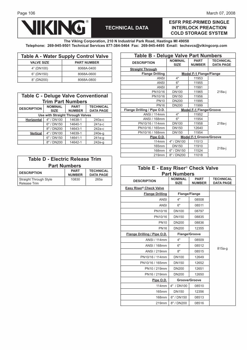
Page 106
TECHNICAL DATA
The Viking Corporation, 210 N Industrial Park Road, Hastings MI 49058Telephone: 269-945-9501 Technical Services 877-384-5464 Fax: 269-945-4495 Email: [email protected]
ESFR PRE-PRIMED SINGLE INTERLOCK PREACTION COLD STORAGE SYSTEM
March 07, 2008
Table C - Deluge Valve Conventional Trim Part Numbers
DESCRIPTION NOMINAL SIZE
PARTNUMBER
TECHNICAL DATA PAGE
Use with Straight Through ValvesHorizontal 4" / DN100 14638-1 240a-c
6" / DN150 14640-1 241a-c8" / DN200 14643-1 242a-c
Vertical 4" / DN100 14639-1 240e-g6" / DN150 14641-1 241e-g8" / DN200 14642-1 242e-g
Table D - Electric Release TrimPart Numbers
DESCRIPTION PARTNUMBER
TECHNICAL DATA PAGE
Straight Through StyleRelease Trim
10830 265a
Table B - Deluge Valve Part NumbersDESCRIPTION NOMINAL
SIZEPART
NUMBERTECHNICAL DATA PAGE
Straight Through Flange Drilling Model F-1 Flange/Flange
ANSI 4" 11953
218a-j
ANSI 6" 11955ANSI 8" 11991
PN10/16 DN100 11965PN10/16 DN150 11956
PN10 DN200 11995PN16 DN200 11999
Flange Drilling / Pipe O.D. Model F-1 Flange/GrooveANSI / 114mm 4" 11952
218a-jANSI / 168mm 6" 11954
PN10/16 / 114mm DN100 11958PN10/16 / 165mm DN150 12640PN10/16 / 168mm DN150 11954
Pipe O.D. Model F-1 Groove/Groove114mm 4" / DN100 11513
218a-j165mm DN150 11910168mm 6" / DN150 11524219mm 8" / DN200 11018
Table E - Easy Riser® Check ValvePart Numbers
DESCRIPTION NOMINAL SIZE
PART NUMBER
TECHNICAL DATA PAGE
Easy Riser® Check Valve Flange Drilling Flange/Flange
815a-g
ANSI 4" 08508
ANSI 6" 08511
PN10/16 DN100 08797
PN10/16 DN150 08835
PN10 DN200 08836
PN16 DN200 12355
Flange Drilling / Pipe O.D. Flange/GrooveANSI / 114mm 4" 08509
ANSI / 168mm 6" 08512
ANSI / 219mm 8" 08515
PN10/16 / 114mm DN100 12649
PN10/16 / 165mm DN150 12652
PN10 / 219mm DN200 12651
PN16 / 219mm DN200 12650
Pipe O.D. Groove/Groove114mm 4" / DN100 08510
165mm DN150 12356
168mm 6" / DN150 08513
219mm 8" / DN200 08516
Table A - Water Supply Control ValveVALVE SIZE PART NUMBER4” (DN100) 8068A-0400
6” (DN150) 8068A-0600
8” (DN200) 8068A-0800
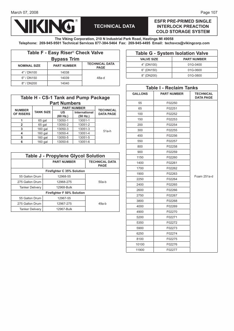
Page 107March 07, 2008
TECHNICAL DATAESFR PRE-PRIMED SINGLE
INTERLOCK PREACTION COLD STORAGE SYSTEM
The Viking Corporation, 210 N Industrial Park Road, Hastings MI 49058Telephone: 269-945-9501 Technical Services 877-384-5464 Fax: 269-945-4495 Email: [email protected]
Table J - Propylene Glycol SolutionPART NUMBER TECHNICAL DATA
PAGEFirefi ghter C 35% Solution
55 Gallon Drum 12968-55
50a-b275 Gallon Drum 12968-275
Tanker Delivery 12968-Bulk
Firefi ghter F 50% Solution55 Gallon Drum 12967-55
49a-b275 Gallon Drum 12967-275
Tanker Delivery 12967-Bulk
Table H - CS-1 Tank and Pump PackagePart Numbers
NUMBER OF RISERS TANK SIZE
PART NUMBER TECHNICAL DATA PAGEUS
(60 Hz.)International
(50 Hz.)1 65 gal 13050-1 13051-1
51a-h
2 65 gal 13050-2 13051-23 160 gal 13050-3 13051-34 160 gal 13050-4 13051-45 160 gal 13050-5 13051-56 160 gal 13050-6 13051-6
Table I - Reclaim TanksGALLONS PART NUMBER TECHNICAL
DATA PAGE55 F02250
Foam 251a-d
65 F02251
100 F02252
150 F02253
200 F02254
300 F02255
450 F02256
550 F02257
800 F02258
900 F02259
1150 F02260
1400 F02261
1700 F02262
1900 F02263
2250 F02264
2400 F02265
2600 F02266
2750 F02267
3800 F02268
4000 F02269
4900 F02270
5200 F02271
5350 F02272
5900 F02273
6250 F02274
8100 F02275
10100 F02276
11900 F02277
Table G - System Isolation ValveVALVE SIZE PART NUMBER4” (DN100) 01G-0400
6” (DN150) 01G-0600
8” (DN200) 01G-0800
Table F - Easy Riser® Check Valve Bypass Trim
NOMINAL SIZE PART NUMBER TECHNICAL DATA PAGE
4" / DN100 14038
48a-d6" / DN150 14039
8" / DN200 14040
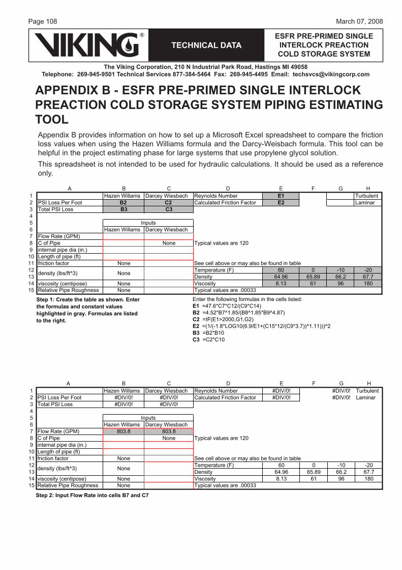
Page 108
TECHNICAL DATA
The Viking Corporation, 210 N Industrial Park Road, Hastings MI 49058Telephone: 269-945-9501 Technical Services 877-384-5464 Fax: 269-945-4495 Email: [email protected]
ESFR PRE-PRIMED SINGLE INTERLOCK PREACTION COLD STORAGE SYSTEM
March 07, 2008
APPENDIX B - ESFR PRE-PRIMED SINGLE INTERLOCK PREACTION COLD STORAGE SYSTEM PIPING ESTIMATING TOOLAppendix B provides information on how to set up a Microsoft Excel spreadsheet to compare the friction loss values when using the Hazen Williams formula and the Darcy-Weisbach formula. This tool can be helpful in the project estimating phase for large systems that use propylene glycol solution.This spreadsheet is not intended to be used for hydraulic calculations. It should be used as a reference only.
HGFEDCB1 Hazen Willams Darcey Wiesbach Reynolds Number E1 Turbulent2 PSI Loss Per Foot B2 C2 Calculated Friction Factor E2 Laminar3 Total PSI Loss B3 C3456 Hazen Willams Darcey Wiesbach7 Flow Rate (GPM)8 021eraseulavlacipyTenoNepiPfoC9 internal pipe dia (in.)10 Length of pipe (ft)11 elbatnidnuofeboslayamroevoballeceeSenoNrotcafnoitcirf12 Temperature (F) 60 0 -10 -2013 7.762.6698.5669.46ytisneD14 viscosity (centipose) None 081691631.8ytisocsiV15 3000.eraseulavlacipyTenoNssenhguoRepiPevitaleR 3
B2 =4.52*B7^1.85/(B8^1.85*B9^4.87)C2 =IF(E1>2000,G1,G2)E2 =(1/(-1.8*LOG10(6.9/E1+(C15*12/(C9*3.7))^1.11)))^2B3 =B2*B10C3 =C2*C10
Enter the following formulas in the cells listed:E1 =47.6*C7*C12/(C9*C14)
Step 1: Create the table as shown. Enter the formulas and constant values highlighted in gray. Formulas are listed to the right.
Inputs
density (lbs/ft^3) None
A
HGFEDCB1 Hazen Willams Darcey Wiesbach Reynolds Number #DIV/0! #DIV/0! Turbulent2 PSI Loss Per Foot #DIV/0! #DIV/0! Calculated Friction Factor #DIV/0! #DIV/0! Laminar3 Total PSI Loss #DIV/0! #DIV/0!456 Hazen Willams Darcey Wiesbach7 Flow Rate (GPM) 803.8 803.88 021eraseulavlacipyTenoNepiPfoC9 internal pipe dia (in.)10 Length of pipe (ft)11 elbatnidnuofeboslayamroevoballeceeSenoNrotcafnoitcirf12 Temperature (F) 60 0 -10 -2013 7.762.6698.5669.46ytisneD14 viscosity (centipose) None 081691631.8ytisocsiV15 33000.eraseulavlacipyTenoNssenhguoRepiPevitaleR
Step 2: Input Flow Rate into cells B7 and C7
Inputs
density (lbs/ft^3) None
A
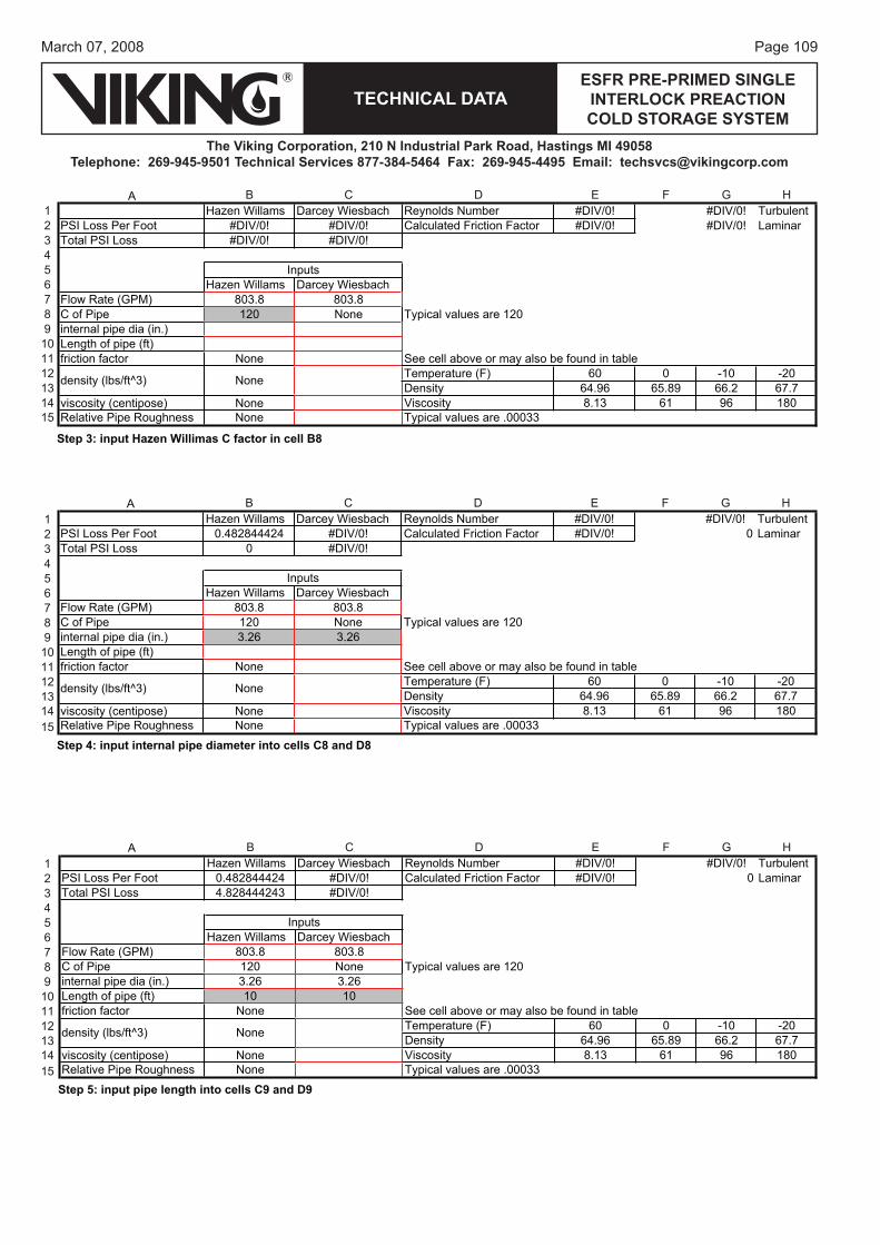
Page 109March 07, 2008
TECHNICAL DATAESFR PRE-PRIMED SINGLE
INTERLOCK PREACTION COLD STORAGE SYSTEM
The Viking Corporation, 210 N Industrial Park Road, Hastings MI 49058Telephone: 269-945-9501 Technical Services 877-384-5464 Fax: 269-945-4495 Email: [email protected]
HGFEDCB1 Hazen Willams Darcey Wiesbach Reynolds Number #DIV/0! #DIV/0! Turbulent2 PSI Loss Per Foot #DIV/0! #DIV/0! Calculated Friction Factor #DIV/0! #DIV/0! Laminar3 Total PSI Loss #DIV/0! #DIV/0!456 Hazen Willams Darcey Wiesbach7 Flow Rate (GPM) 803.8 803.88 021eraseulavlacipyTenoN021epiPfoC9 internal pipe dia (in.)10 Length of pipe (ft)11 elbatnidnuofeboslayamroevoballeceeSenoNrotcafnoitcirf12 Temperature (F) 60 0 -10 -2013 7.762.6698.5669.46ytisneD14 viscosity (centipose) None 081691631.8ytisocsiV15 33000.eraseulavlacipyTenoNssenhguoRepiPevitaleR
Step 3: input Hazen Willimas C factor in cell B8
Inputs
density (lbs/ft^3) None
A
HGFEDCBHazen Willams Darcey Wiesbach Reynolds Number #DIV/0! #DIV/0! Turbulent1
ranimaL0!0/VID#rotcaFnoitcirFdetaluclaC!0/VID#424448284.0tooFrePssoLISP2Total PSI Loss 0 #DIV/0!3
45
Hazen Willams Darcey Wiesbach6Flow Rate (GPM) 803.8 803.87
021eraseulavlacipyTenoN021epiPfoC8internal pipe dia (in.) 3.26 3.269Length of pipe (ft)10
elbatnidnuofeboslayamroevoballeceeSenoNrotcafnoitcirf11Temperature (F) 60 0 -10 -2012
7.762.6698.5669.46ytisneD13viscosity (centipose) None 081691631.8ytisocsiV14
33000.eraseulavlacipyTenoNssenhguoRepiPevitaleR15Step 4: input internal pipe diameter into cells C8 and D8
Inputs
density (lbs/ft^3) None
A
HGFEDCBHazen Willams Darcey Wiesbach Reynolds Number #DIV/0! #DIV/0! Turbulent1
ranimaL0!0/VID#rotcaFnoitcirFdetaluclaC!0/VID#424448284.0tooFrePssoLISP2Total PSI Loss 4.828444243 #DIV/0!3
45
Hazen Willams Darcey Wiesbach6Flow Rate (GPM) 803.8 803.87
021eraseulavlacipyTenoN021epiPfoC8internal pipe dia (in.) 3.26 3.269Length of pipe (ft) 10 1010
elbatnidnuofeboslayamroevoballeceeSenoNrotcafnoitcirf11Temperature (F) 60 0 -10 -2012
7.762.6698.5669.46ytisneD13viscosity (centipose) None 081691631.8ytisocsiV14
33000.eraseulavlacipyTenoNssenhguoRepiPevitaleR15Step 5: input pipe length into cells C9 and D9
Inputs
density (lbs/ft^3) None
A
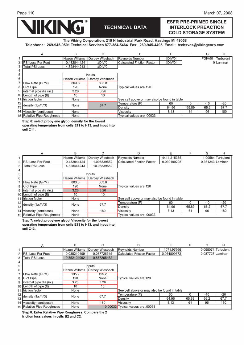
Page 110
TECHNICAL DATA
The Viking Corporation, 210 N Industrial Park Road, Hastings MI 49058Telephone: 269-945-9501 Technical Services 877-384-5464 Fax: 269-945-4495 Email: [email protected]
ESFR PRE-PRIMED SINGLE INTERLOCK PREACTION COLD STORAGE SYSTEM
March 07, 2008
HGFEDCBHazen Willams Darcey Wiesbach Reynolds Number #DIV/0! #DIV/0! Turbulent1
ranimaL0!0/VID#rotcaFnoitcirFdetaluclaC!0/VID#424448284.0tooFrePssoLISP2Total PSI Loss 4.828444243 #DIV/0!3
45
Hazen Willams Darcey Wiesbach6Flow Rate (GPM) 803.8 803.87
021eraseulavlacipyTenoN021epiPfoC8internal pipe dia (in.) 3.26 3.269Length of pipe (ft) 10 1010
elbatnidnuofeboslayamroevoballeceeSenoNrotcafnoitcirf11Temperature (F) 60 0 -10 -2012
7.762.6698.5669.46ytisneD13viscosity (centipose) None 081691631.8ytisocsiV14
33000.eraseulavlacipyTenoNssenhguoRepiPevitaleR15
Step 6: select propylene glycol density for the lowest operating temperature from cells E11 to H13, and input into cell C11.
Inputs
density (lbs/ft^3) None 67.7
A
HGFEDCBHazen Willams Darcey Wiesbach Reynolds Number 4414.215365 1.00584 Turbulent1
PSI Loss Per Foot 0.482844424 1.005839552 Calculated Friction Factor 0.039199298 0.361243 Laminar2Total PSI Loss 4.828444243 10.058395523
45
Hazen Willams Darcey Wiesbach6Flow Rate (GPM) 803.8 803.87
021eraseulavlacipyTenoN021epiPfoC8internal pipe dia (in.) 3.26 3.269Length of pipe (ft) 10 1010
elbatnidnuofeboslayamroevoballeceeSenoNrotcafnoitcirf11Temperature (F) 60 0 -10 -2012
7.762.6698.5669.46ytisneD13viscosity (centipose) None 180 081691631.8ytisocsiV14
33000.eraseulavlacipyTenoNssenhguoRepiPevitaleR15Step 7: select propylene glycol Viscosity for the lowest operating temperature from cells E13 to H13, and input into cell C13.
Inputs
density (lbs/ft^3) None 67.7
A
HGFEDCBHazen Willams Darcey Wiesbach Reynolds Number 1071.97666 0.098074 Turbulent1
PSI Loss Per Foot 0.035210409 0.087726545 Calculated Friction Factor 0.064809672 0.087727 Laminar2Total PSI Loss 0.352104092 0.8772654523
45
Hazen Willams Darcey Wiesbach6Flow Rate (GPM) 195.2 195.27
021eraseulavlacipyTenoN021epiPfoC8internal pipe dia (in.) 3.26 3.269Length of pipe (ft) 10 1010
elbatnidnuofeboslayamroevoballeceeSenoNrotcafnoitcirf11Temperature (F) 60 0 -10 -2012
7.762.6698.5669.46ytisneD13viscosity (centipose) None 180 081691631.8ytisocsiV14Relative Pipe Roughness None 0.00033 Typical values are .0003315
Step 8: Enter Relative Pipe Roughness. Compare the 2 friction loss values in cells B2 and C2.
Inputs
density (lbs/ft^3) None 67.7
A

Form No. F_122807