establishing an arc flash loss prevention program that can be used to calculate best risk management...
TRANSCRIPT
A White Paper
Establishing an Arc Flash Loss Prevention Program
By John F. Welch, Jr., Marvin O. Tibbetts, III,
Apostolos Vranis, P.E. and Robert E. Hoyt, Ph.D.
©M.C. Dean, 2008

M.C. DEAN, INC. WHITE Establishing an Arc Flash Loss Prevention Program
©M.C. Dean, 2008 2
PAPER
Table of Contents
1 EXECUTIVE SUMMARY ........................................................................................... 3
2 PURPOSE OF THIS WHITE PAPER .......................................................................... 3
3 GENERAL INFORMATION ....................................................................................... 3
3.1 WHAT IS AN ARC FLASH? ......................................................................................... 3 3.2 WHAT CAUSES AN ARC FLASH? ................................................................................. 4 3.3 WHAT ARE THE RESULTING INJURIES FROM AN ARC FLASH? ........................................... 4 3.4 WHAT ARE THE RESULTING BUSINESS CONSEQUENCES OF AN ARC FLASH? ....................... 4 3.5 WHO ARE THE AUTHORITIES? ................................................................................... 4
4 WHO IS RESPONSIBLE? ......................................................................................... 5
5 “THOU SHALL” – SAYS WHO? ................................................................................. 6
OSHA’S STANDARDS AND ENFORCEMENT POLICIES .............................................................. 6
6 PUBLISHED COMPLIANCE & STANDARDS GUIDELINES .......................................... 6
6.1 WARNING & LABELING: NEC-2002 .......................................................................... 7 6.2 IMPLEMENTING THE WORK PRACTICES: NFPA 70E-2004 .............................................. 7
7 CAUTION: USING SIMPLIFIED TABLES & IEEE STANDARD 1584 CHARTS ............. 7
8 HERE IS HOW – AN ARC FLASH LOSS PREVENTION (AFLP) PROGRAM ................... 7
8.1 RISK MANAGEMENT APPLIED .................................................................................... 8 8.2 ARC FLASH LOSS PREVENTION (AFLP) PROGRAM ......................................................... 8
9 CHOOSING THE RIGHT AFLP PARTNER - SELECTION CRITERIA ........................... 10
9.1 TRAINING AND PROGRAM REVIEWS BY CERTIFIED SAFETY OFFICERS .............................. 10 9.2 CUSTOMER SERVICE AND SUPPORT .......................................................................... 11
10 CONCLUSION ........................................................................................................ 11
11 DEFINITION OF TERMS ......................................................................................... 11
12 FREQUENTLY ASKED QUESTIONS ......................................................................... 12
13 ABOUT THE AUTHORS .......................................................................................... 13
13.1 JOHN F. WELCH, JR. ............................................................................................ 13 13.2 MARVIN (MARK) O. TIBBETTS, III ............................................................................ 13 13.3 APOSTOLOS (TOLIS) VRANIS, P.E. ........................................................................... 14 13.4 ROBERT E. HOYT, PH.D. ....................................................................................... 14
14 ABOUT M.C. DEAN, INC. ........................................................................................ 14
15 APPENDIX: OVERVIEWS, TABLES AND ILLUSTRATIONS ....................................... 16
15.1 OVERVIEW – POTENTIAL MITIGATION TECHNIQUES ...................................................... 16 15.2 FIGURE 1 ― ARC FLASH LOSS PREVENTION (AFLP) LIFECYCLE ..................................... 17 15.3 FIGURE 2 ― BOUNDARY APPROACH DIAGRAM* ........................................................... 18 15.4 TABLE 1: APPROACH BOUNDARIES .......................................................................... 19 15.5 TABLE 2: PPE/ARC RATING TABLE* ....................................................................... 20 15.6 FIGURE 3 – HAZARD/RISK ANALYSIS FLOW CHART* ................................................... 21
M.C. DEAN, INC. WHITE PAPER Establishing an Arc Flash Loss Prevention Program
1 Executive Summary The facts are eye opening. An arc flash explosion occurs between five and ten times a day somewhere in the U.S.1 Up to 80% of all electrical injuries are burns resulting from an arc flash and the resultant ignition of flammable clothing.2 Electrical accidents contribute to billions of dollars of lost property and litigation related to injuries and loss of life.3
To reduce the potential for injuries or deaths from arc flash incidents, the Occupational Safety and Health Administration (OSHA) has issued regulations designed to promote workplace safety.4 Concurrently, the National Fire Protection Association (NFPA) is working to “reduce the worldwide burden of fire and other hazards on the quality of life by providing and advocating consensus codes and standards, research, training, and education.”5 Together, these two organizations are setting the industry standard for regulations and standard practices that influence workplace safety.
The industry has responded by designing safer power systems, reducing worker exposure to arc flash energy, and initiating Arc Flash Loss Protection (AFLP) programs. This White Paper will discuss arc flash loss prevention regulations and industry best practices, the causes and effects of arc flash hazards, the need for an AFLP Program, and the steps necessary to implement an effective AFLP Program.
2 Purpose of this White Paper Most arc flash guidance materials available today are written by the engineering community for the engineering community. Yet, it is the middle and upper managers, many of whom do not have engineering or technical backgrounds, who are responsible for making loss prevention decisions, including those aimed at minimizing and mitigating the risk associated with electrical hazards in the workplace. Therefore, this white paper is focused on those individuals accountable for protecting their organizations from harm.
This white paper is designed to:
● Give middle and upper management an executive level description of the details surrounding arc flash and the industry’s best
1http://ecmweb.com/market/electric_arc_flash_safety/ 2 http://www.optimation.us/arcflash.aspx 3 http://en/wikipedia.org/wiki/electric shock # shock _effects 4 OSHA Code of Federal Regulations (CFR) 29, Section 1910.333 (a) (2) 5 NFPA 70E provides the tools and explanations to employees so that they will walk away from an arc flash incident unhurt.
proven business practices. After reading this paper and applying the knowledge gained to his/her organization, executives should have the confidence to begin the process of assigning the right team and resources needed to develop the methodology that best carries out a safety and arc flash loss prevention program tailored to their organizations.
● Provide the technical manager with a support document that can be presented to upper management along with his/her recommended initiatives to improve corporate safety policies by integrating an Arc Flash Loss Prevention (AFLP) Program.
• Provide business leaders a quick reference guide to the questions they may have involving who is responsible (in the eyes of OSHA and the judicial system), how to resource, how to control cost and how to build a sustainable program that can be monitored by a non-technical manager.
● Equip risk managers with a methodology to process a loss prevention program targeted to exposure related to arc flash. This includes the means to identify, evaluate, choose, implement, monitor and manage a comprehensive program that is sustainable and provides measureable data that can be used to calculate best risk management decisions.
● Caution on the use of “over-simplified” allowable tables and charts the industry has developed to establish arc flash protective measures. The risks include controlling the cost of expensive personal protective equipment (PPE) that may or may not be needed and giving untrained workers the false sense of confidence when working on energized electrical equipment. The result is a mismanaged safety program.
3 General Information To better understand the need to protect electrical workers from electric hazards, such as shock, arc-flash, and arc-blast hazards, one must first understand the impact of an arc flash. The following section defines arc flash, lists causes, and details the possible results of an arc flash incident.
3.1 What Is an Arc Flash? An arc flash is a hazardous arcing short circuit or fault, potentially occurring anywhere in an electrical system, phase-to-phase or phase-to-ground. The arcing fault causes rapidly excessive heating of air molecules, ionizes and vaporizes conductive metal materials and generates a densely concentrated blast of pressure formed by light and heat energy.
©M.C. Dean, 2008 3
M.C. DEAN, INC. WHITE PAPER Establishing an Arc Flash Loss Prevention Program
The arc flash blast can propel molten metal, shrapnel, and tools through the air, potentially knocking workers off of ladders and even launching them across a room.6
3.2 What Causes an Arc Flash? There can be numerous causes for an arc flash incident. The most common are human error, neglecting proper preventive maintenance, and an improperly designed electrical system or legacy equipment. The following details each of the above causes:
● Human Error: An arc flash incident could occur due to human error as a result of unsafe work procedures. Most commonly, these mistakes are made during maintenance activities and are caused by mishandling a tool, wire, metal cover, etc.
● Neglecting Proper Preventive Maintenance: An arc flash incident could occur due to neglecting preventive maintenance tasks and activities. Proper preventive maintenance should include:
Checking for loose wiring and improperly torqued electrical terminations;
Cleaning and inspecting electrical equipment to prevent the build-up of dust, dirt, particles, debris or corrosion that could become an arc conductor between live parts;
Periodically testing and operating the electrical equipment’s moving parts that are designed to clear electrical faults;
Adhering to NFPA 70-B Annex I defined maintenance intervals.
● Improperly Designed Electrical System or Legacy Equipment: An arc flash incident could occur due to an improperly designed electrical system, incorrect electrical system modifications and legacy electrical equipment.
3.3 What Are the Resulting Injuries from an Arc Flash?
Between five and ten times a day an arc flash explosion occurs in the United States, according to CapSchell, Inc., a Chicago research company that specializes in workplace accident prevention.
Injuries resulting from an arc flash are typical of an explosion and may include flash burns, hearing loss, vision loss, general trauma and death.
6 http://en.wikipedia.org/wiki/arc_flash
Proper personal protective equipment (PPE) is critical to mitigating injuries. An arc flash incident has the ability to melt man-made fibers to one’s skin. This includes underwear and bras worn under Flame Resistant (FR) clothing. Even FR clothing has an ignition point. Only clothing tested to meet specific calorie ratings can be trusted to withstand arc flash incident energies per their ratings.7
Electrical dangers, including arc flashes, will always be present on the job, but proper installations, training, and safety strategies, processes and procedures for operating and maintaining electrical systems and equipment can minimize the likelihood of injuries and fatalities.
3.4 What Are the Resulting Business Consequences of an Arc Flash?
Arc flash incidents have numerous consequences beyond the obvious, and most serious, which are injury or death of an employee. Additional consequences include:
● Damage to Equipment
● Business Disruption
● Increased Experience Modification Rate (EMR)
● OSHA Citations
● Litigation
● Bad Public Relations
3.5 Who Are the Authorities? Effective August 31, 2007, the Occupational Safety and Health Administration (OSHA) has provided legal motivation to employers to protect from arc flash hazards any personnel who install or maintain electrical systems. The agency published a final ruling in the Federal Register on February 14, 2007 that mandated new guidelines for equipment design, equipment classification, electrical system installation and electrical maintenance practices.
The mission for OSHA, part of the Department of Human and Health Services, is “to assure the safety and health of America's workers by setting and enforcing standards; providing training, outreach, and education; establishing partnerships; and encouraging continual improvement in workplace safety and health.” This makes OSHA the nation’s preeminent enforcer of workplace safety regulations.8
The National Fire Protection Association (NFPA), established in 1896, serves as the world's leading
7 www.westexinc.com 8 www.osha.gov
©M.C. Dean, 2008 4
M.C. DEAN, INC. WHITE PAPER Establishing an Arc Flash Loss Prevention Program
advocate of fire prevention and is an authoritative source on public safety. In fact, the NFPA's 300 codes and standards influence every building, process, service, design, and installation in the United States, as well as many of those used in other countries. The NFPA publishes both the NFPA 70 National Electrical Code (NEC) and the Standard for Electrical Safety in the Workplaces (NFPA 70E). These publications are nationally recognized as providing the industry’s acceptable standard practices used by federal, state and local building authorities to regulate safe electrical installation and maintenance. The NFPA’s purpose is to “reduce the worldwide burden of fire and other hazards on the quality of life by providing and advocating consensus codes and standards, research, training, and education.”9
The NFPA routinely updates their publications which allow local and state building authorities to adopt these changes into their laws and ordinances.
OSHA’s previous update to its general-industry electrical standard was in 1981 and its renewed effort in 2007 adds multi-agency consistency, as it aligns itself more closely with the 2000 edition of the NFPA 70E-2000 and the 2002 edition of the NEC-2002.
The American Society of Safety Engineers (ASSE) represents 30,000 safety, health and environmental professionals committed to safety in the workplace. In a letter to OSHA in 2004, ASSE’s president wrote, “It is appropriate to move forward with this revision, given the seriousness of electrical hazards and the fact that nearly 300 workers are killed each year from contact with electrical current or as the result of injuries caused by fires and explosions related to electrical accidents.”
Guidelines recently published by the Institute of Electrical and Electronics Engineers (IEEE), has developed “IEEE Standard 1584, Guide for Performing Arc Flash Hazardous Calculations.” The purpose of IEEE 1584 is to:
“Provide techniques for designers and facility operators to apply in determining the arc flash hazard distance and the incident energy to which employees could be exposed during their work on or near electrical equipment.”10
The IEEE guide provides the means of identifying and quantifying potential arc flash hazards so that proper labeling and personal protective equipment (PPE) can be selected.
9 “Guide to the Conduct of Participants in the NFPA Codes
and Standards Development Process,” November 2003. www.nfpa.org. Retrieved May 24, 2008 10http://grouper.ieee.org/groups/1584/index.html
The American National Standards Institute (ANSI) is a non-profit organization that is the voice of U.S. standards and conformity assessment system. Its members are required to be accredited. The ANSI mission is to:
“Enhance both the global competitiveness of U.S. business and the U.S. quality of life by promoting and facilitating voluntary consensus standards and conformity assessment systems, and safeguarding their integrity.”
The NFPA and IEEE are both members of ANSI.11
The National Institute for Occupational Safety and Health (NIOSH) is the federal agency responsible for conducting research and making recommendations for the prevention of work-related injury and illness. NIOSH is part of the Centers for Disease Control (CDC) in the Department of Health and Human Services (DHHS). NIOSH includes research and development for the Mine Safety and Health Administration (MSHA). A separate agency from OSHA, MSHA, part of DHHS, is the safety and health inspection and enforcement agency for nation’s mines includes coal, gravel, sand, stone, and metal amongst others.
In 2007, NIOSH recognized arc flash as the most common cause of electrical industry in the mining workplace. Also in 2007, NIOSH published “Understanding and Quantifying Arc Flash Hazards in the Mining Industry.” In this paper, NIOSH states:
“Arc flash hazards are an issue that has not yet been effectively addressed in the mining industry, but intervention strategies and techniques developed in other industries over the last two decades can be applied to help solve this problem. NFPA 70E, Standard for Electrical Safety in the Workplace, is the most comprehensive and widely used source for recommendations on this topic.”12
4 Who Is Responsible? In OSHA’s General Duty Clause and the Multiple-Employer Citation Policy Section 5(a)(1) of the Occupational Safety and Health Act, employers are required to furnish their employees a place of employment free from recognized hazards that cause or are likely to cause death or serious physical harm to the employees.13
In addition to the employers who directly employ the exposed electrical workers, building owners, property managers, facility managers and general contractors have responsibility to the process as
11 http://www.ansi.org 12 http://www.cdc.gov/niosh/about/html 13 OSHA CFR 29 USC 654-200
©M.C. Dean, 2008 5
M.C. DEAN, INC. WHITE PAPER Establishing an Arc Flash Loss Prevention Program
well. In response to the Associated Building Contractors’ concerns on this subject, OSHA posted on its website these definitions of the four employer role categories:14
● Exposing: This is an employer whose own employees are exposed to the hazard.
● Creating: This is an employer who creates a hazard to which a different employer’s employees are exposed.
● Correcting: This is an employer who has been brought in to specifically correct a hazard.
● Controlling: This is an employer with general supervisory authority over the worksite with the authority to have safety and health violations corrected.15
5 “Thou Shall” – Says Who? As stated earlier, OSHA regulations, effective August 31, 2007, mandate that employers shall protect employees from electrical hazards. OSHA is clearly the lead enforcer, and is supported by both the NFPA 70E-2004 and NEC-2005.
OSHA’s Standards and Enforcement Policies In the United States, the Office of the Federal Register (OFR) is the official archive of laws published by Congress, presidential documents, descriptions of federal agencies and the regulations by which they govern.
OSHA’s mission, as pointed out previously is to assure the safety and health of U.S. workers. The agency’s governance includes both setting and enforcing standards.
OSHA recorded its new electrical safety standards in the Federal Register on February 14, 2007 (Department of Labor, OSHA, 29-CFR, Part 1910, Electrical Standard, Final Rule). These standards became enforceable on August 31, 2007.
In this government archive, OSHA states:
“The Occupational Safety and Health Administration (OSHA) is revising the general industry electrical installation standard found in Subpart S of 29 CFR Part 1910. The Agency has determined that electrical hazards in the workplace pose a significant risk of injury or death to employees, and that the requirements in the revised standard, which draw heavily from the 2000 edition of the National Fire Protection Association’s (NFPA) Electrical Safety Requirements for Employee Workplaces (NFPA 70E),
14http://www.osha.gov/pls/oshaweb/owadisp. show_document?p_table=news_releases&p_id=501 15 Ibid.
and the 2002 edition of the National Electrical Code (NEC), are reasonably necessary to provide protection from these hazards. This final rule focuses on safety in the design and installation of electric equipment in the workplace. This revision will provide the first update of the installation requirements in the general industry electrical installation standard since 1981. OSHA is also replacing the reference to the 1971 NEC in the mandatory appendix to the general industry powered platform standard found in Subpart F of 29 CFR Part 1910 with a reference to OSHA’s electrical installation standard.”
(To view the latest NFPA and NEC regulations, visit the NFPA website, http://www.nfpa70national electricalcode.com.)
OSHA regulations state in 1910.333 (a) that workers should not work on live equipment (greater than 50 volts) except for one of two reasons:
● If de-energizing introduces additional or increased hazards such as the shutdown of ventilation to a hazardous location, interruption of life support equipment, or deactivation of emergency alarm systems.
● If it is infeasible due to equipment design or operational limitations such as when voltage testing is required for diagnostics.
When it is necessary to work on energized equipment, workers should follow safe work practices including assessing the risks, wearing proper PPE, and using the proper tools.
6 Published Compliance & Standards Guidelines
The NFPA led diligently with IEEE to gather a true consensus among other agencies, industry associations and industry organizations to create with accreditation from ANSI compliance standards and guidelines to improve and mitigate hazards in the workplace surrounding arc flash.
The NFPA’s current industry standards publications referencing arc flash protection practices include:
● How to Warn and Label: NEC-2002; and
● How to Implement Work Practices: NFPA 70E-2004.
(For a complete understanding and a review of the NFPA 70E, visit the NFPA web site at http://www.nfpa.org/aboutthecodes/AboutTheCodes.asp?DocNum=70E.)
The following subsections of that code detail the scope of information provided by the NFPA:
©M.C. Dean, 2008 6
M.C. DEAN, INC. WHITE PAPER Establishing an Arc Flash Loss Prevention Program
6.1 Warning & Labeling: NEC-2002 NEC-2002, 2005, 2008 Article 110.16, covering the provision for flash protection, states that electrical equipment “likely to require examination, adjustment, servicing, or maintenance while energized shall be field marked to warn qualified persons of potential electric arc flash hazards.” It makes reference in FPN No.1 to NFPA 70E-2000 that provides the associated work practices and is described below. The article makes reference in FPN No. 2 to the ANSI Z535.4-1998 specification that provides the industry’s recognized standard for product safety signs and warning labels.
Note: Even though OSHA references NEC-2002 in its revisions to Subpart S of 29 CFR Part 1910, the governing regulations were developed specifically to minimize the need for revision as new standards to the NEC are released. Therefore, to date, NEC 2008 is the recommended standard to follow.
6.2 Implementing the Work Practices: NFPA 70E-2004
This standard provides guidance on implementing appropriate work practices required to safeguard workers from injury while working on or near exposed electrical conductors or circuit parts that could become energized. Some requirements of NFPA 70E-2004 include:
● Equipment must be placed in a safe working condition;
● Personal Protective Equipment (PPE) must be worn when work is conducted within a flash protection boundary. This work includes lockout/tagout, testing, and inspecting visual breaks within flash boundaries of energized equipment; and
● Facility owners are required to perform a flash hazard analysis prior to allowing a worker to work on energized equipment. This is necessary for determining the flash protection boundary and type of PPE required.
Note: Even though OSHA references NFPA 70E-2000 in its revisions to Subpart S of 29 CFR Part 1910, the governing regulations were developed specifically to minimize the need for revision as new standards from the NFPA are released. Therefore, to date, the NFPA 70E-2004 is the current consensus standard to follow in the industry.
7 CAUTION: Using Simplified Tables & IEEE Standard 1584 Charts
It is best practice and is always recommended that workers follow de-energized lockout/tagout safety procedures while working on electrical equipment.
However, when workers must work on energized electrical equipment, they must be qualified to do so, be made aware of the hazards and follow proper work practices as described in NFPA 70E. This includes wearing proper personal protective equipment (PPE).16
This section addresses the concern with using the published tables. These charts allow for simplified analysis techniques to determine the required arc flash PPE based on IEEE Standard 1584.
IEEE states that:
“While the method does not exactly calculate incident energy levels and flash protection boundaries at the buses under consideration, it does allow for an accurate determination of required PPE levels and maximum flash-protection boundary distances.”
Using this technique could create the environment for the following:
● Restrictive Safety Equipment: For example, Category 4 PPE is a full suit with hood that is restrictive. Working in a Category 4 suit is very slow, time consuming, and air flow restrictive. A Category 4 suit also limits the field of vision and does not allow reasonable dexterity on complex work. Having to default to maximum flash-protection boundaries could make the use of the required PPE unreasonable and increase the likelihood of human error.
● Mismanaged Safety Program: The same discipline that seeks simplicity may roll into expensive purchase orders for PPE, improper inventory control, improper use, and documentation control; i.e. permitting for energized work.
● False Sense of Security: Any part of the safety program can put untrained workers and others at risk by misinterpreting the PPE as “maximum protection” when, in this instance, lockout/tagout procedures would provide the adequate protection.
It is important to understand the organizations’ real electrical arc flash hazards and to create a culture that focuses on the true seriousness of an arc flash. Misapplication creates unforeseen hazards that can lead to loss and elevated costs.
8 Here Is How – An Arc Flash Loss Prevention (AFLP) Program
OSHA has provided the legal motivation for an AFLP program by setting and enforcing new arc flash
16 NFPA 70E, 2004 EDITION, Ray A. Jones, page 25, section 130.3 (B)
©M.C. Dean, 2008 7
M.C. DEAN, INC. WHITE PAPER Establishing an Arc Flash Loss Prevention Program
protection regulations. Additionally, the NFPA established some reference guidelines and recommendations to identify and implement an arc flash protection strategy/program. Finally, the electrical engineering community has developed recommended products and professional services to implement arc flash protection. Unfortunately, too often due to poor execution and application of these services and products, an organization is exposed to the risk of an incident, OSHA fines, and damaged reputation.
8.1 Risk Management Applied A serious gap exists in most arc flash programs today. These programs are not sustainable unless there is a process that assures:
• Complete List of Electrical Assets
• Risk Assessment
• Hazards are Identified & Labeled
• Established Processes
• Trained Personnel
• Document Control
• Management Controls
• Reviewed & Updated
This section 8.0 specifically addresses the necessary steps to build a sustainable Arc Flash Loss Prevention (AFLP) Program and gives information that risk managers and others can use. Some major areas commonly missed include:
● Identifying: Discovering the complete electrical system, including the intent of the engineered design, system changes, and any unforeseen electrical arc flash hazards that may exist in the electrical system.
● Evaluating: Assessing the potential frequency and severity of risk associated with each electrical system asset discovered by performing a site specific engineered arc flash analysis, documenting each electrical asset to its level of risk and labeling it accordingly in the field.
● Quantifying: Equipping risk management with the ability to quantify the number of electrical assets by severity and the frequency by which personnel are exposed to the risk of arc flash. With this information, risk management can decide the emphasis to place on loss control measures to avoid, retain and/or insure the risk associated with arc flash.
● Developing & Controlling Process: Assuring that OSHA’s and NFPA’s regulations and recommended work practices are properly
integrated to the organization’s work flow processes. This includes work ticket initiation, work practices in the field, field documentation, work history logging and safety program enforcement.
● Training: Assuring that program consistency is accomplished with an ongoing training program that is integrated into the corporate safety program process. This includes initial employee training, new employee orientation, employee scheduled refresher training, outside contractor/vendor compliance training and AFLP program updates.
● Protecting: Establishing a program to identify proper types and inventory of Personal Protection (PPE) is readily available for use, is properly being applied, and is routinely inspected to assure it’s protective reliability.
● Controlling Cost: Developing a measured approach to spending money on expensive PPE. Haphazardly buying equipment just for show is expensive and creates hazards in itself by giving a false sense of security putting workers in harms way when they don’t even realize it.
● Documenting: Assuring that the organization is ready for an OSHA audit that could occur unannounced without an incident or as a follow-up behind one. OSHA is pretty straight forward: “If it’s not documented, it didn’t happen.” An AFLP Program assures the documentation process properly occurs to show training, work processes, engineering updates and electrical asset identification updates.
● Reviewing & Updating: Any sustainable process has a method to track, evaluate and improve. A sustainable AFLP is no different and should place the controls in the hands of management.
An Arc Flash Loss Prevention (AFLP) Program goes beyond an Arc Flash Analysis and Arc Flash Study. A site-specific engineered analysis and study are critical pieces. However, an AFLP Program is a commitment to safety for zero accidents by a comprehensive process that assures sustainability by incorporating discovery, engineering, identification, reporting, administrative planning, training, field execution, documentation control, program review, and annual program updates. These are the elements that answer the question: “What happens when…?”
8.2 Arc Flash Loss Prevention (AFLP) Program
An effective AFLP Program is not something that can be created and then ignored. The true value of an
©M.C. Dean, 2008 8
M.C. DEAN, INC. WHITE PAPER Establishing an Arc Flash Loss Prevention Program
AFLP Program can only be determined after it has been implemented and the long term reduction in arc flash incidents documented. This requires a program that continually evolves as equipment and technology evolve and as personnel come into and out of the program. To accomplish this, the program must be viewed as cyclical with each step in the lifecycle of the program. New information must be incorporated to ensure the safety of the workers is paramount and uncompromised. Figure 1, presented in the Appendix, illustrates the AFLP Program lifecycle and highlights the interdependency of each of six steps involved in the process. These six steps are described in detailed below.
8.2.1 Discovery & Engineering
AFLP Program discovery initially involves gathering pre-existing engineering data. For a new construction project, the data is pulled from the design and construction drawings. Existing facilities will require site visits to verify the engineering data and drawings (to the extent that such exist). AFLP Program discovery also includes interviews, historical failures and fault data collection, and data gathering on the facilities’ department operating process associated with issuing and maintaining records that involve work tickets / purchase orders for electrical maintenance activities.
AFLP Program engineering and analysis derived from the discovery details will result in updated risk assessments, recommended system improvements (risk/reward notes), engineered and design improve coordination studies, and updated electrical diagrams.
8.2.2 Identification & Documentation
Each electrical asset must be labeled and identified with a warning label that meets the ANSI Z535.4-1998 specification per the reference in NEC-2002 or later revision.
AFLP Program submittals should include accumulated data used for risk assessments, electrical asset inventory list, arc flash category results, engineered drawings, TCC curves, breakers and fuses, set points, and copies of labels.
8.2.3 Program Preparation & Administration
Key elements of program administration include:
● Listing staff responsibilities and documenting the AFLP Program process for internal coordination;
● Creating the AFLP Program document designed for electrical asset control;
● Initiating Personal Protective Equipment (PPE) selection. PPE inventory levels should be based on the probability of use, AFLP Program category classification, number of personnel, size, voltage classes, boundary levels; and
● Initiating the AFLP Program Standard Operational Procedure manual submission tailored to the specific facility. This manual shall be updated annually and cataloged accordingly.
8.2.4 Program Training & Certification
To ensure that an AFLP Program remains in compliance, one must invest in certified AFLP Program training for its personnel. This includes:
● Providing administrative staff AFLP Program training for personnel who approve and issue work tickets, coordinate with outside contractors, and maintain activities logs.
● Providing field worker certified AFLP Program training to “qualify” personnel to work on the facility’s electrical system. This includes initial startup, ongoing and new employee training, as well as the methodology used to train outside contractors.
8.2.5 Field Execution & Document Control
Field execution and document control are essential elements of an AFLP Program. They include:
● Integrating AFLP Program methods into internal maintenance work tickets, change control and service history records.
● Integrating AFLP Program methods into external service providers such as outside contractors. These include credentialing, control of scope of work, change control, and as-built documentation.
8.2.6 Program Review & Update
On a quarterly or bi-annual basis, depending on the complexity and history of the program, it is important to review the previous period’s experience and activities. This includes interviews with field personnel, staff and management. It also includes a review of field documentation and field inspection (visual) for accurate records, logs, and electrical system modifications that need to be labeled and classified.
On an annual basis, all the maintenance records, interviews and system modifications should be reviewed and records updated. From this activity, the newly updated annual AFLP Program Standard Operating Procedural manual shall be put into use
©M.C. Dean, 2008 9

M.C. DEAN, INC. WHITE PAPER Establishing an Arc Flash Loss Prevention Program
along with updated engineering drawings and records.
An effective AFLP Program includes more than the initial electrical engineering arc flash analysis that many professional service companies are performing today. Establishing a comprehensive program that is sustainable is a much more complex undertaking. It includes creating the checks and balances that assure program continuity. The six-step AFLP Program process, which is both proven and tested, helps avoid accidents, reduces risk and provides responsible document control as proof that the program is in compliance with OSHA and the NFPA.
9 Choosing the Right AFLP Partner – Selection Criteria
Selecting an AFLP Program facilitating partner is an important step in creating an AFLP Program. Critical evaluation factors include:
● Engineering capabilities,
● Employment of certified safety officers,
● Experience and specific industry expert is,
● Software capabilities, and
● Customer service and support.
An AFLP Program facilitating partner should be credentialed in programs similar to the program that is best suited to the facility. Important factors to consider include:
● Selecting an electrical engineering firm that is trustworthy, developed specific industry expertise and has experience in the specific type of operation, facility and safety requirements needed.
● Asking the AFLP Program firm for the resumes of individuals who will work on the project. This should include engineers, electricians and safety officers.
● Asking for a discovery safety plan and making sure the partnering firm is trained in NFPA 70E.
● Obtaining sample deliverables that include engineering calculations and reports, warning labels, operating procedures, etc.
● Ensuring that the firm has engineers, electricians and safety officers on staff. One should avoid firms that subcontract some of their services. This outsourcing may show either inexperience in specific areas or inability to properly resource.
● Asking the AFLP Program firm for references for similar jobs (scope, complexity, etc.)
● Asking the AFLP Program firm partner to guarantee its reporting and submissions will be reviewed and signed by a professional engineer (P.E.)
The leading engineering organizations will use arc flash analysis software to perform their arc flash studies. Some software is not electrical system wide verified and validated for arc flash application and of limited value because it is specialized for specific equipment manufacturers. The real value of the software is an electrical system-wide verified and validated program, which adheres to NFPA and IEEE pertinent standards, and is supported by the equipment inventory technical library used for short circuit, load flow and coordination studies.
Engineering accuracy, efficiency, being able to perform the proper analytics and providing the information needed to make solid electrical system recommendations are critical. It takes an un-biased technical catalog to do so. When reviewing arc flash analysis software, it is critical to understand the software’s limitations. It is also critical that the AFLP partnering firm understands:
● OSHA’s newest requirements in 29 CFR Part 1910 Subpart S,
● NFPA 70E-2004 standards,
● IEEE 1584, and
● NEC-2008 standards.
A professional AFLP Program firm must be able to create engineering records and one-line electrical diagrams with incident energy levels and arc flash boundaries.
9.1 Training and Program Reviews by Certified Safety Officers
An AFLP Program firm must have a professional safety program, which supports the commitment to safety for zero accidents. The AFLP Program firm shall produce resumes that show the proposed safety professionals who will work on the program have the proper credentials and a demonstrated commitment to safety for zero accidents. Those credentials should come from two of the nation’s top safety credentialing organizations are the Board of Certified Safety Professionals (BCSP) and the American Society of Safety Engineers (ASSE).
The AFLP Program firm’s safety officers shall have the knowledge and experience to train personnel on NFPA 70E, lockout /tagout, OSHA penalties, the limitations of “unqualified” workers, identifying energized components, and determining equipment voltage classes.
©M.C. Dean, 2008 10
M.C. DEAN, INC. WHITE PAPER Establishing an Arc Flash Loss Prevention Program
9.2 Customer Service and Support The AFLP Program firm shall understand the electric utility’s configuration, short circuit capability and the available fault currents entering the facility. The ability to access accurate data from the electric utility is critical to ensuring all of the calculations fundamentally align.
The AFLP Program provider must be experienced and have the capability to create recommendations and options to mitigate and lower the risks associated with arc flash for both the proposed (new) or existing installation. These recommendations, as stated in the Potential Mitigation Techniques Overview in the Appendix, may include changes to the types of overcurrent protection, selectivity of settings for different settings between operation and maintenance, corrective adjustments and other recommendations that could reduce or eliminate arc flash hazards. (An additional benefit of reducing or eliminating hazards is to downsize the arc flash category, which reduces the PPE cal/cm2 requirements.) Any recommendations made by the AFLP Program provider shall include a scope and budget.
10 Conclusion Electrical dangers, including arc flash will always be present on the job, but with proper designs, installations, processes, procedures, training, and safety strategies/programs, the likelihood of arc flash can be minimized and thus injuries and fatalities can be prevented. The cornerstone of any strategy to reduce arc flash hazards is a properly defined, implemented and administrated Arc Flash Loss Protection Program.
11 Definition of Terms Certain words and phrases are specific to any discussion of arc flash hazards and are, therefore, vital to understanding the OSHA and NFPA regulations and guidelines.
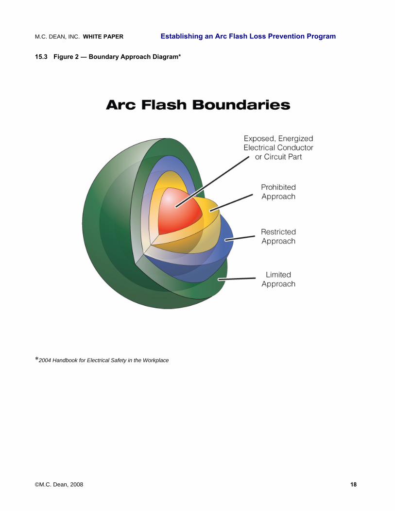
Arc Flash Boundaries
The three classifications of arc flash boundaries are 1) Limited Approach, 2) Restricted Approach, and 3) Prohibited Approach. These boundaries are distances determined from the potential origination source of the arcing fault which produces 1.2 calories/cm2 incident energy.
Figure 2, provided in the Appendix, illustrates the distance for each boundary from the potential origination point of the arc flash. Note: This is equal to holding your finger over the tip of a flame from a common household lighter for one second.
The following are descriptions of each boundary.
● Limited Approach Boundary: The boundary around exposed, live parts that may not be crossed by “unqualified” person(s) unless accompanied by a “qualified” person(s).
● Restricted Approach Boundary: The boundary that marks the area from exposed energized “live” parts that may be crossed only by “qualified” persons using appropriate shock prevention techniques and equipment.
● Prohibited Approach Boundary: The boundary that marks the area from exposed energized “live” parts that may be crossed only by “qualified” persons using the same type of protection as if direct contact with live parts is planned.
(See Table 1 for detailed distances for Approach Boundaries to Live Parts/or Shock Protection.)
Arcing Time
Arcing time is the amount of time that the arc flash incident has the potential to last depending on the electrical system’s settings of the upstream overcurrent protective devices.
Calorie
A calorie is a unit of measure for the amount of energy required to raise one gram of water one degree Celsius at one atmosphere. Second degree burns occur at 1.2 calories per centimeter squared per second.
Distance
The distance an individual is from an arc flash originating source. In more sophisticated electrical systems, equipment manufacturers have begun using remote operating equipment, circuit breaker racking, and other means to place distance between personnel and potential arc flash sources.
Fault Current
Fault current is the abnormal flow of electrical current due to an electrical fault condition. Overcurrent devices (i.e. circuit breakers, fuses, etc.) are designed in electrical systems to protect electrical circuits from too much current flow. They work by interrupting fault currents. The method of protection is commonly known as “tripping a breaker” or “blowing a fuse.” If a circuit is to be properly protected, the fault current must be high enough to operate the primary protective device within as short a time as possible. Also, the protective device must be able to withstand the fault current and extinguish internally any resulting arcs without sustaining the external arc for any significant length of time.
©M.C. Dean, 2008 11
M.C. DEAN, INC. WHITE PAPER Establishing an Arc Flash Loss Prevention Program
Flash Hazard
A dangerous condition associated with the release of energy caused by an electric arc.
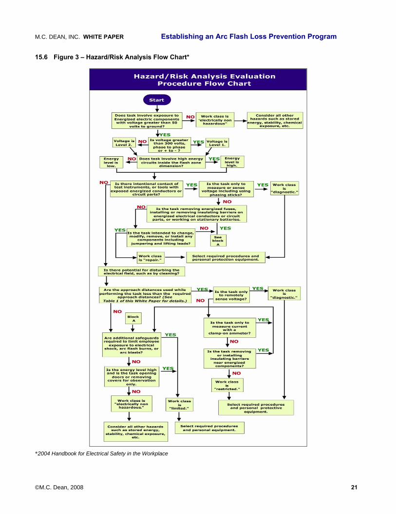
Hazard / Risk Category
The hazard/risk category is the danger level of the potential arc flash incident. The category ratings range from 0 to 4. Category 0 represents little or no risk and Category 4 represents the greatest risk. Table 2, provided in the Appendix, shows the types of PPE needed for each category.
Determining the actions once a hazard is identified is the key. (See Figure 3, a flow chart that outlines the evaluation procedure for Hazard/Risk Analysis.)
Qualified Worker
A qualified worker is defined as an individual who has received documented training in the hazards of working on energized equipment in general, and has been trained in the hazards of the particular equipment being serviced. Training must include the necessary information to protect him or herself from arc flash hazards including the use of proper procedures and the application of PPE.
12 Frequently Asked Questions When it comes to understanding the importance of an AFLP Program and how an arc flash can impact an organization, people ask a lot of questions. This section answers those most frequently asked questions.
Why is a flash hazard analysis necessary?
First, the NFPA 70E-2004 requires facility owners to perform a flash hazard analysis prior to allowing a worker to work on energized equipment. This analysis is necessary to determine the flash protection boundaries and the type of PPE that must be worn.
How long does an Arc Flash analysis take?
It obviously depends on the size of the plant. The analysis requires inspections of all electrical bus’s nameplate data, conduit type, length and feeder type (AL or CU). The typical site should take, on average, 45 minutes per bus. 17
What if one only wants to do an arc flash analysis?
An arc flash analysis is a good first step. An ongoing program with training, procedures, checks and balances, and documentation offers much greater risk reduction.
17 Timeframe based on actual Arc Flash analyses conducted by M.C. Dean, Inc.
If an organization always subcontracts its electrical work when energized work needs to be performed, isn’t the subcontractor accountable, thus no need for an Arc Hazard Study?
Yes. The subcontractor is accountable for understanding the incident energy level, and the building owner is accountable for ensuring a safe work environment. If an accident occurs, OSHA will fine the building owner and will still consider the building owner at fault.
If an employee from an outside company is injured while working on electrical equipment, is the organization that hired the outside company liable for damages?
Yes. According to OSHA, employers must ensure safe work environments for ALL who come in contact with electrical equipment.
What is an AFLP program?
AFLP stands for Arc Flash Loss Protection. An AFLP Program is a comprehensive process that assures complete program sustainability. Components include discover, engineering, identification, reporting, administrative planning, training, field execution, documentation control, program review and annual program updates.
Why should an AFLP program be sustainable?
A true Arc Flash Loss Prevention Program must be ongoing, not just analyzing or testing equipment. An organization needs a comprehensive AFLP program PLUS one that sets up training programs for new employees, updates documentation and reports and constantly works to reduce risks and accidents.
If an arc flash occurs and an organization doesn’t have an AFLP Program in place, what can happen?
Besides the risk of someone being terribly injured, burned, disfigured or even killed, an organization will also face fines from OSHA, the possibility of litigation, damaged reputation and a public relations nightmare. The risks of an arc flash are too great not to implement an AFLP Program.
Can an AFLP program be tailored specifically to an organization?
Yes. An engineering firm that is an expert in AFLP will know how to determine a facility’s needs and understand processes, budgets, staff resources and infrastructure.
Will an AFLP program prevent all electrical accidents from happening?
Although the possibility of an electrical accident, including arc flashes, will always be present on the job, proper design, installation, training and safety
©M.C. Dean, 2008 12

M.C. DEAN, INC. WHITE PAPER Establishing an Arc Flash Loss Prevention Program
strategies/programs can minimize the likelihood of those accidents and prevent injuries and fatalities.
What is PPE and when is it required?
PPE stands for Personal Protection Equipment used to safeguard employees who work on electrical equipment. PPE must be worn when work is conducted within flash protection boundaries, such as lockout/tagout, testing and inspecting visual breaks.
13 About the Authors
13.1 John F. Welch, Jr. John Welch is a highly qualified electrical engineer with more than 14 years of experience in the design, implementation, operation, and maintenance of electrical systems. He is a proven leader with the ability to take projects from feasibility to completion. He joined M.C. Dean, Inc.’s Service and Critical Support Division in January 2007 as a Group Manager.
Under his direction, the CPG provides the engineering, installation, critical support, and preventive maintenance programs. At M.C. Dean, Inc., Mr. Welch worked on a number of critical power projects including large data center expansion efforts for Equinix and Verio corporations and the delivery of critical power services for Federal government clients such as the Department of Defense.
Prior to joining M.C. Dean, Inc., Mr. Welch was a Technical Product Manager with I Power Energy Systems. He was accountable for several strategic projects, including a new product launch. He was the Lead Engineer of I Power Energy Systems, a startup company that provided low emissions distributed generation equipment to customers in the United States and Korea. He launched 33 units in 2005 and 70 receivables in 2006. He also led the product re-alignment efforts and the development of an 8.1L aggregation well pump boosting monthly revenue by 20%. In addition, Mr. Welch identified and signed 12 distribution partners, energy service companies, and architectural design firms.
Before joining I Power Energy, he was the Engines Program Manager for DTE Energy Technologies in Michigan and was accountable for the 2007 CARB emission compliance.
Mr. Welch holds a Master of Science degree in Industrial Operations from Lawrence Technological University and a Bachelor of Science degree in Electronic Engineering from DeVry Technological University. He holds a Journeyman Electrician license in Michigan, and is trained in NFPA 70E.
13.2 Marvin (Mark) O. Tibbetts, III Mark Tibbetts is President/General Manager of Tibs, a division of M. C. Dean. He assumed that role in December 2004 when M.C. Dean, Inc., acquired Tibs Group, a business that Mr. Tibbetts’ family owned and operated for over 30 years.
Mr. Tibbetts joined Tibs Group while still in school, working first part time and then full time after he graduated from West Georgia College with a degree in business.
Starting as an electrical apprentice, he would work in practically every role in the family business including technical field positions, field management positions, estimating, engineering, project management, and client management, learning the business from the top down.
He was instrumental in expanding the company’s operations from an electrical contracting business by launching the firm’s telecommunications group. In 1996, Mr. Tibbetts became the President and CEO of the company.
Over the next eight years, he guided the company as it expanded programs focused on serving industrial and commercial clients who were critically dependent on technology and complex electrical systems to run their operations which include power quality assurance services, electrical preventative maintenance services, critical power services, safety training, building automation, and electronic security systems.
A partial list of clients developed and served under his leadership include Delta Airlines, Bank of America, Emory University, Coca Cola, Hewlett Packard, Georgia Power, Southern Company, the Centers for Disease Control, BellSouth, AT&T, State Farm Insurance, SunGard Availability Services, Georgia Pacific, United Parcel Service, Federal Express, Raytheon, Oglethorpe Power Corporation, Georgia Transmission, Vulcan Materials, LaFarge Aggregates, Hansen Materials, the State Board of Regents and MBNA.
Mr. Tibbetts is accredited by BICSI as a Registered Communication Distribution Designer (RCDD). He is a member of the Atlanta Independent Electrical Contractors (IEC) and previous member of their Board of Directors. He serves on the Board of Directors for the Gwinnett Chamber of Commerce, the Gwinnett Technical College Foundation Board as a Bank Director for Georgia Trust Bank and on Gwinnett’s Fellowship of Christian Athletes’ Board of Directors. He was named the Gwinnett Chamber of Commerce Small Business Person of the Year in 2003 and the 2002 Member of the Year by Atlanta IEC.
©M.C. Dean, 2008 13
M.C. DEAN, INC. WHITE PAPER Establishing an Arc Flash Loss Prevention Program
13.3 Apostolos (Tolis) Vranis, P.E. Vice President of Electrical Engineering for M.C. Dean, Inc., Apostolos (Tolis) Vranis has more than 26 years experience in progressive professional engineering with 16 of those years as a lead engineer and supervisor with Bechtel. He has in-depth experience in electrical engineering and design for MV and LV substations, transformer stations, multi-fuel power generation plants, various types of desalination plants, transmission and distribution.
Mr. Vranis is an expert in all voltage levels in electrical engineering system studies, paralleling and controlling of dissimilar transformers, electrical equipment and cable sizing, relay protection systems and coordination studies. He has been involved and performed electrical engineering studies and optimized designs for mission critical electrical systems, labs and biological research centers, datacenters and super-computer power distribution systems.
Conversant in both North American and European codes and standards, he developed and reviewed electrical designs for control rooms, battery and UPS rooms, switchgear buildings, turbine halls, boiler islands, auxiliary power and desalination plant buildings and process buildings for nuclear waste clean-up and chemical weapon demilitarization sites.
Mr. Vranis coauthored the Power System Concepts for the Lunar Outpost technical paper for NASA. At Bechtel he was engineering lead for a $360 million 340 MW CC power and desalination project in Abu Dhabi and a $626 million, 600 MW, project in Saudi Arabia. He also led subcontractor’s engineering, detailed design and construction work for 13 rehabilitation and 14 new substations for the $1.3 billion Iraq Infrastructure Reconstruction Program as well as led the Oracle Database Design Group at Browns Ferry Nuclear Power Plant in Alabama.
Prior to joining Bechtel, he worked in Toronto for nine years at Poulos Engineering as an Electrical Engineer, at Lavalin-Shawinigan as an Electrical Group Supervisor and Sherwood Electrical as an Electrical Engineer. Mr. Vranis has an MS degree in Electrical Engineering.
13.4 Robert E. Hoyt, Ph.D. Robert E. Hoyt is the Dudley L. Moore, Jr. Chair of Risk Management and Insurance in the Terry College of Business at the University of Georgia. He teaches corporate risk management and enterprise risk management and serves as the Department Head for Insurance, Legal Studies, and Real Estate. He was Interim Dean of the Terry College in 2007 and has been on the UGA faculty since 1988. He is a recipient of the Richard B. Russell Outstanding
Undergraduate Teaching Award from UGA and the Teacher of the Year Award from the Terry College. In 2006 he received the Terry College’s Outstanding Service Award.
Dr. Hoyt holds a degree in actuarial science from the University of Nebraska and M.A. and Ph.D. degrees in risk and insurance from the Wharton School of the University of Pennsylvania where he was an S.S. Huebner Fellow. In 1995 he was a Fulbright Visiting Professor of Risk Management at the Vienna University of Economics and Business Administration, and he studied at the University of Cologne, Germany.
His research interests are focused in the areas of corporate hedging, enterprise risk management, catastrophe risk management, the economics of insurance fraud, liability system costs and insurer insolvency. His research has appeared in various scholarly and trade journals including the Journal of Risk and Insurance, the Journal of Risk and Uncertainty, the Journal of Law and Economics, the North American Actuarial Journal, the Journal of Business Finance and Accounting, Risk Management and Insurance Review, the Journal of Insurance Regulation, the Journal of Insurance Issues, the CPCU Journal and the Journal of Actuarial Practice. Dr. Hoyt has served as a risk management consultant to various public and private sector organizations including the U.S. Department of Homeland Security.
Dr. Hoyt is Past President of the American Risk and Insurance Association, Past President of the Risk Theory Society, Past President of the Southern Risk and Insurance Association, a board member of the International Insurance Society, and a member of the Risk and Insurance Management Society, the Western Risk and Insurance Association, and the American Finance Association. He serves on the Board of Directors of the Journal of Insurance Regulation and on the editorial board of Risk Management and Insurance Review. He holds the professional designations of CLU and ChFC.
14 About M.C. Dean, Inc. M.C. Dean, Inc. is one of the nation's premier design/build electrical engineering firms, offering solutions for protection of critical infrastructure and key assets, continuity of operations, and related engineering support. The firm offers full lifecycle support, from requirements analysis and design, through construction, installation, and testing, to operations and maintenance.
Their solutions support more than 3000 uniformed and civilian federal government agencies, state and municipal governments, transit authorities, public utilities, biopharmaceutical firms, health care
©M.C. Dean, 2008 14
M.C. DEAN, INC. WHITE Establishing an Arc Flash Loss Prevention Program
©M.C. Dean, 2008 15
PAPER
facilities, educational institutions and Fortune 1000 firms worldwide. M.C. Dean, Inc. employs nearly 3000 personnel at 22 offices worldwide, and has a six decade history of high quality, on time, on budget service delivery.
M.C. Dean, Inc. is exclusively dedicated to lifecycle solutions for electrical and electronic systems. Areas of expertise include power distribution systems construction, testing and maintenance, high voltage cabling, critical power systems, substation design,
substation and distribution automation, energy management systems, generation and control, environmental management, and lighting systems.
Mastery of the state of the art, comprehensive technical capabilities, streamlined service delivery, and effective project management are just a few of the reasons that public and private sector entities have selected M.C. Dean, Inc. to meet their mission-critical needs.
M.C. DEAN, INC. WHITE Establishing an Arc Flash Loss Prevention Program
©M.C. Dean, 2008 16
PAPER
15 Appendix: Overviews, Tables and Illustrations
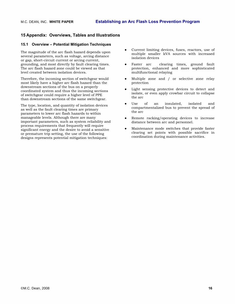
15.1 Overview – Potential Mitigation Techniques
The magnitude of the arc flash hazard depends upon several parameters, such as voltage, arcing distance or gap, short-circuit current or arcing current, grounding, and most directly by fault clearing times. The arc flash hazard zone could be viewed as that level created between isolation devices.
Therefore, the incoming section of switchgear would most likely have a higher arc flash hazard than the downstream sections of the bus on a properly coordinated system and thus the incoming sections of switchgear could require a higher level of PPE than downstream sections of the same switchgear.
The type, location, and quantity of isolation devices as well as the fault clearing times are primary parameters to lower arc flash hazards to within manageable levels. Although there are many important parameters, such as system reliability and process requirements that frequently will require significant energy and the desire to avoid a sensitive or premature trip setting, the use of the following designs represents potential mitigation techniques:
● Current limiting devices, fuses, reactors, use of multiple smaller kVA sources with increased isolation devices
● Faster arc clearing times, ground fault protection, enhanced and more sophisticated multifunctional relaying
● Multiple zone and / or selective zone relay protection
● Light sensing protective devices to detect and isolate, or even apply crowbar circuit to collapse the arc
● Use of an insulated, isolated and compartmentalized bus to prevent the spread of the arc
● Remote racking/operating devices to increase distance between arc and personnel.
● Maintenance mode switches that provide faster clearing set points with possible sacrifice in coordination during maintenance activities.

M.C. DEAN, INC. WHITE Establishing an Arc Flash Loss Prevention Program
©M.C. Dean, 2008 17
PAPER
15.2 Figure 1 ― Arc Flash Loss Prevention (AFLP) Lifecycle
M.C. DEAN, INC. WHITE Establishing an Arc Flash Loss Prevention Program
©M.C. Dean, 2008 18
PAPER
15.3 Figure 2 ― Boundary Approach Diagram*
*2004 Handbook for Electrical Safety in the Workplace
M.C. DEAN, INC. WHITE Establishing an Arc Flash Loss Prevention Program
©M.C. Dean, 2008 19
PAPER
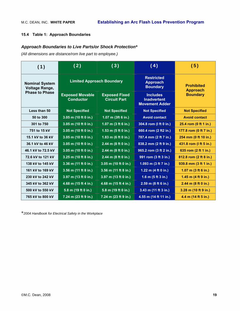
15.4 Table 1: Approach Boundaries
Approach Boundaries to Live Parts/or Shock Protection* (All dimensions are distance/rom live part to employee.)
(1) (2) (3) (4) (5)
Nominal System Voltage Range, Phase to Phase
Limited Approach Boundary
Restricted Approach Boundary
Prohibited Approach Boundary Exposed Movable
Conductor Exposed Fixed
Circuit Part Includes
Inadvertent Movement Adder
Less than 50 Not Specified Not Specified Not Specified Not Specified
50 to 300 3.05 m (10 ft 0 in.) 1.07 m (3ft 6 in.) Avoid contact Avoid contact
301 to 750 3.05 m (10 ft 0 in.) 1.07 m (3 ft 6 in.) 304.8 rom (I ft 0 in.) 25.4 rom (0 ft 1 in.)
751 to 15 kV 3.05 m (10 ft 0 in.) 1.53 m (5 ft 0 in.) 660.4 rom (2 ft2 in.) 177.8 rom (0 ft 7 in.)
15.1 kV to 36 kV 3.05 m (10 ft 0 in.) 1.83 m (6 ft 0 in.) 787.4 mm (2 ft 7 in.) 254 mm (0 ft 10 in.)
36.1 kV to 46 kV 3.05 m (10 ft 0 in.) 2.44 m (8 ft 0 in.) 838.2 mm (2 ft 9 in.) 431.8 rom (I ft 5 in.)
46.1 kV to 72.5 kV 3.05 m (10 ft 0 in.) 2.44 m (8 ft 0 in.) 965.2 rom (3 ft 2 in.) 635 rom (2 ft 1 in.)
72.6 kV to 121 kV 3.25 m (10 ft 8 in.) 2.44 m (8 ft 0 in.) 991 rom (3 ft 3 in.) 812.8 rom (2 ft 8 in.)
138 kV to 145 kV 3.36 m (11 ft 0 in.) 3.05 m (10 ft 0 in.) 1.093 m (3 ft 7 in.) 939.8 mm (3 ft 1 in.)
161 kV to 169 kV 3.56 m (11 ft 8 in.) 3.56 m (11 ft 8 in.) 1.22 m (4 ft 0 in.) 1.07 m (3 ft 6 in.)
230 kV to 242 kV 3.97 m (13 ft 0 in.) 3.97 m (13 ft 0 in.) 1.6 m (5 ft 3 in.) 1.45 m (4 ft 9 in.)
345 kV to 362 kV 4.68 m (15 ft 4 in.) 4.68 m (15 ft 4 in.) 2.59 m (8 ft 6 in.) 2.44 m (8 ft 0 in.)
500 kV to 550 kV 5.8 m (19 ft 0 in.) 5.8 m (19 ft 0 in.) 3.43 m (11 ft 3 in.) 3.28 m (10 ft 9 in.)
765 kV to 800 kV 7.24 m (23 ft 9 in.) 7.24 m (23 ft 9 in.) 4.55 m (14 ft 11 in.) 4.4 m (14 ft 5 in.)
*2004 Handbook for Electrical Safety in the Workplace

M.C. DEAN, INC. WHITE Establishing an Arc Flash Loss Prevention Program
©M.C. Dean, 2008 20
PAPER
15.5 Table 2: PPE/Arc Rating Table*
*Table based on NFPA 70E-2004
M.C. DEAN, INC. WHITE Establishing an Arc Flash Loss Prevention Program
©M.C. Dean, 2008 21
PAPER
15.6 Figure 3 – Hazard/Risk Analysis Flow Chart*
*2004 Handbook for Electrical Safety in the Workplace