et-200s position 6es7 138 4ca01 0ab0
DESCRIPTION
ET 200S POSITION MODULETRANSCRIPT
Positioning
___________________
___________________
___________________
SIMATIC
ET 200S Positioning
Operating Instructions
06/2010 A5E00124872-05
Preface 1
1STEP 5V
2
1PosUniversal
3
Legal information
Legal information Warning notice system
This manual contains notices you have to observe in order to ensure your personal safety, as well as to prevent damage to property. The notices referring to your personal safety are highlighted in the manual by a safety alert symbol, notices referring only to property damage have no safety alert symbol. These notices shown below are graded according to the degree of danger.
DANGER indicates that death or severe personal injury will result if proper precautions are not taken.
WARNING indicates that death or severe personal injury may result if proper precautions are not taken.
CAUTION with a safety alert symbol, indicates that minor personal injury can result if proper precautions are not taken.
CAUTION without a safety alert symbol, indicates that property damage can result if proper precautions are not taken.
NOTICE indicates that an unintended result or situation can occur if the corresponding information is not taken into account.
If more than one degree of danger is present, the warning notice representing the highest degree of danger will be used. A notice warning of injury to persons with a safety alert symbol may also include a warning relating to property damage.
Qualified Personnel The product/system described in this documentation may be operated only by personnel qualified for the specific task in accordance with the relevant documentation for the specific task, in particular its warning notices and safety instructions. Qualified personnel are those who, based on their training and experience, are capable of identifying risks and avoiding potential hazards when working with these products/systems.
Proper use of Siemens products Note the following:
WARNING Siemens products may only be used for the applications described in the catalog and in the relevant technical documentation. If products and components from other manufacturers are used, these must be recommended or approved by Siemens. Proper transport, storage, installation, assembly, commissioning, operation and maintenance are required to ensure that the products operate safely and without any problems. The permissible ambient conditions must be adhered to. The information in the relevant documentation must be observed.
Trademarks All names identified by ® are registered trademarks of the Siemens AG. The remaining trademarks in this publication may be trademarks whose use by third parties for their own purposes could violate the rights of the owner.
Disclaimer of Liability We have reviewed the contents of this publication to ensure consistency with the hardware and software described. Since variance cannot be precluded entirely, we cannot guarantee full consistency. However, the information in this publication is reviewed regularly and any necessary corrections are included in subsequent editions.
Siemens AG Industry Sector Postfach 48 48 90026 NÜRNBERG GERMANY
A5E00124872-05 06/2010
Copyright © Siemens AG 2010. Technical data subject to change
Positioning Operating Instructions, 06/2010, A5E00124872-05 3
Table of contents
1 Preface ...................................................................................................................................................... 5 2 1STEP 5V.................................................................................................................................................. 7
2.1 Product overview ...........................................................................................................................7 2.2 Isochronous mode .........................................................................................................................9 2.3 Safety concept .............................................................................................................................10 2.4 Brief description of how to commission the 1STEP 5V ...............................................................11 2.5 Terminal Assignment Diagram.....................................................................................................16 2.6 Fundamentals of Positioning........................................................................................................18 2.6.1 Overview ......................................................................................................................................18 2.6.2 Parameters and Settings .............................................................................................................19 2.6.3 Traversal curve of the 1STEP 5V ................................................................................................20 2.6.4 Setting the Base Frequency.........................................................................................................23 2.7 Functions of the 1STEP 5V..........................................................................................................25 2.7.1 Overview ......................................................................................................................................25 2.7.2 Search for Reference...................................................................................................................26 2.7.3 Sequence of Execution of the Search for Reference ..................................................................28 2.7.4 Set home position ........................................................................................................................31 2.7.5 Relative incremental mode (relative positioning) .........................................................................32 2.7.6 Absolute incremental mode (absolute positioning) ......................................................................33 2.7.7 Speed-control mode.....................................................................................................................34 2.7.8 Hold traversing job .......................................................................................................................36 2.7.9 Axis type and traversing range ....................................................................................................38 2.7.10 Pulse Enable................................................................................................................................40 2.7.11 Changing Parameters during Operation ......................................................................................41 2.7.12 Behavior of the Digital Inputs .......................................................................................................42 2.7.13 Behavior at CPU-Master-STOP...................................................................................................44 2.8 Parameter assignment.................................................................................................................45 2.9 Diagnostics...................................................................................................................................47 2.9.1 Diagnostics using the LED display ..............................................................................................47 2.9.2 Error types....................................................................................................................................48 2.10 Feedback and Control Interface ..................................................................................................49 2.10.1 Assignment of the Feedback and Control Interfaces...................................................................49 2.10.2 Traversing job, changing parameters and troubleshooting .........................................................56 2.11 Technical Specifications ..............................................................................................................59
Table of contents
Positioning 4 Operating Instructions, 06/2010, A5E00124872-05
3 1PosUniversal ......................................................................................................................................... 61 3.1 Product overview......................................................................................................................... 61 3.2 Safety concept ............................................................................................................................ 63 3.3 Brief Instructions on Commissioning the 1PosU......................................................................... 64 3.4 Terminal Assignment Diagram.................................................................................................... 70 3.5 Fundamentals of Controlled Positioning Using Rapid/Creep Feed ............................................ 72 3.6 Functions of the 1PosU............................................................................................................... 75 3.6.1 Overview of the Functions........................................................................................................... 75 3.6.2 Axis, Drive and Encoder.............................................................................................................. 79 3.6.3 Effect of the Directional Enables................................................................................................. 82 3.6.4 Stop (MODE 0)............................................................................................................................ 83 3.6.5 Inching (MODE 1) ....................................................................................................................... 84 3.6.6 Reference Point Run (MODE 3) ................................................................................................. 86 3.6.7 Relative Positioning (MODE 4) ................................................................................................... 93 3.6.8 Absolute Positioning (MODE 5) .................................................................................................. 96 3.6.9 Canceling JOB Processing (JOB 0)............................................................................................ 99 3.6.10 Setting the Actual Value (JOB 1) .............................................................................................. 100 3.6.11 Moving the Encoder Range (JOB 2) ......................................................................................... 102 3.6.12 Changing the Switch-Off Difference (JOB 3) ............................................................................ 104 3.6.13 Changing the Switchover Difference (JOB 4) ........................................................................... 105 3.6.14 Evaluating the Reference Signal (JOB 9) ................................................................................. 106 3.6.15 Latch Function (JOB 10) ........................................................................................................... 108 3.6.16 Setting the Monitoring of the Direction of Rotation (JOB 11).................................................... 110 3.6.17 Displaying Current Values (JOB 15) ......................................................................................... 112 3.6.18 Error Detection/Diagnostics ...................................................................................................... 114 3.7 CPU/Master Stop and RESET State......................................................................................... 121 3.8 Parameter List........................................................................................................................... 122 3.9 Diagnostics................................................................................................................................ 129 3.9.1 Diagnostics using the LED display............................................................................................ 129 3.9.2 Error Types of Channel-Specific Diagnostics ........................................................................... 130 3.10 Control and Feedback Signals.................................................................................................. 131 3.11 Technical Specifications............................................................................................................ 134
Index...................................................................................................................................................... 139
Positioning Operating Instructions, 06/2010, A5E00124872-05 5
Preface 1
How the Manual is Structured This manual is supplementary to the ET 200S Distributed I/O System operating instructions. The ET 200S Distributed I/O System (http://support.automation.siemens.com/WW/view/en/1144348) operating instructions provide comprehensive information pertaining to the hardware configuration, installation, wiring, commissioning, diagnostics and technical specifications of the ET 200S distributed I/O system. This manual provides a description of functions and the technical specifications of the ET 200S modules for positioning tasks: 1STEP 5V and 1PosUniversal.
How to Find Your Way Around At the beginning of each section you will find a Product Overview, which lists the features and applications of the module described. You will also find the order number of the module and the name and release of the software required. For the current GSD file, go to: http://www.automation.siemens.com/csi/gsd In each section you will then find a section with the heading Brief Instructions on Commissioning followed by the name of the relevant module. These brief instructions tell you in a series of short steps how to install and configure the module, how to integrate it in your use program, and how to test it in your user program.
Index The index contains keywords that come up in the manual.
Standards and approvals For information about standards and approvals, refer to the section "General technical specifications" in the ET 200S Distributed I/O System (http://support.automation.siemens.com/WW/view/en/1144348) operating instructions.
Recycling and disposal The ET 200S 1STEP 5V and ET 200S 1PosUniversal modules can be recycled due to the non-toxic materials from which they are assembled. For environmentally sustainable recycling and disposal of your old device, contact a certified disposal service for electronic scrap.
Preface
Positioning 6 Operating Instructions, 06/2010, A5E00124872-05
Additional support If you have any further questions about the use of products described in this manual and do not find the right answers here, contact your local Siemens representative (http://www.siemens.com/automation/partner): A guide to the technical documentation for the various products and systems is available on the Internet: SIMATIC Guide manuals (http://www.siemens.com/simatic-tech-doku-portal) The online catalog and online ordering systems are also available on the Internet: A&D Mall (http://www.siemens.com/automation/mall)
Training center To help you get started with automation technology and systems, we offer a variety of courses. Contact your regional Training Center or the central Training Center in D-90327 Nuremberg, Germany. Internet: SITRAIN homepage (http://www.sitrain.com)
Technical Support You can access technical support for all A&D projects via the following: Online support request form: (http://www.siemens.com/automation/support-request)
Service & Support on the Internet In addition to our documentation, we offer a comprehensive online knowledge base on the Internet at: Industry Automation and Drive Technologies - Homepage (http://www.siemens.com/automation/service&support) There you will find the following information, for example: The newsletter that provides up-to-date information on your products. The documents you need via our Search function in Service & Support. A forum for global information exchange by users and specialists. Your local partner for Automation and Drives. Information about on-site service, repairs, and spare parts. Much more can be found
under "Services".
Positioning Operating Instructions, 06/2010, A5E00124872-05 7
1STEP 5V 22.1 Product overview
Order number 6ES7 138-4DC01-0AB0
Description The 1STEP 5V generates pulses for the power units of stepping motors. The number of pulses emitted determines the distance traversed. The pulse frequency determines the velocity. The change in the pulse frequency per time unit (second) is a measure for the acceleration or deceleration. A stepping motor shaft turns by a certain angle with every pulse. During rapid pulse sequences, this stepping movement becomes a continuous turning motion.
Compatibility The 1STEP 5V with the order number 6ES7 138-4DC01-0AB0 replaces the 1STEP 5V/204kHz with the order number 6ES7 138-4DC00-0AB0 compatibly.
Features The 1STEP 5V has the following characteristic features: Modes:
– Reference point approach – Relative incremental mode (relative positioning) – Absolute incremental mode (absolute positioning) – Speed-control mode – Set home position
Can be used with STEP 7 Version V5.4 SP4 and later in non-isochronous and isochronous modes.
Interface to commonly available stepping motor power units with differential signals for pulses and direction to RS 422
Maximum output frequency 510 kHz Distance up to 16 777 215 (= 224 – 1) pulses Support of linear and modulo axes (rotary axes) Function and active level of the digital inputs can be configured
1STEP 5V 2.1 Product overview
Positioning 8 Operating Instructions, 06/2010, A5E00124872-05
Type of the feedback value can be set in the feedback interface (residual distance, position or frequency)
Firmware update 1) Identification data 1) 1) The function is only available if the used interface module supports the required system services.
Configuration In order to configure the 1STEP 5V use one of the following options STEP 7 as of Version V5.4 SP4 with the HSP 2068 (Hardware Support Package from the
Internet) A GSD file (http://www.automation.siemens.com/csi/gsd)
Firmware update In order to extend the functionality and eliminate errors, firmware updates can be downloaded to the 1STEP 5V using STEP 7 HW Config.
Note When you launch the firmware update, the old firmware is deleted. If the firmware update is interrupted or canceled for any reason, the 1STEP 5V will no longer function correctly as a result. Restart the firmware update and wait until it has completed successfully.
Identification data The following identification data are stored on the 1STEP 5V: Hardware version Firmware product version Serial number For additional information, refer to the "Identification data" section in the ET 200S Distributed I/O System (http://support.automation.siemens.com/WW/view/en/1144348) operating instructions.
1STEP 5V 2.2 Isochronous mode
Positioning Operating Instructions, 06/2010, A5E00124872-05 9
2.2 Isochronous mode
Note For basic information on isochronous mode, refer to the Isochronous mode (http://support.automation.siemens.com/WW/view/en/15218045) function manual.
Hardware requirements You will require the following for the 1STEP 5V in isochronous mode: A CPU that supports isochronous mode PROFIBUS master or PROFINET controller that supports the constant bus cycle time IM 151 that supports isochronous mode
Response of the 1STEP 5V Depending on the system parameter assignment, the 1STEP 5V works in either non-isochronous or isochronous mode. In isochronous mode Motion commands are started or stopped isochronously. The feedback interface is updated isochronously. All 8 bytes of the user data interface are consistent. If a parameter assignment error occurs, the 1STEP 5V does not go into isochronous mode. If isochronous mode fails due to faults or failure/delay of global control (GC), the 1STEP 5V returns to isochronous mode during the next cycle without an error response. If isochronous mode fails, the user data interface is no longer updated synchronously.
1STEP 5V 2.3 Safety concept
Positioning 10 Operating Instructions, 06/2010, A5E00124872-05
2.3 Safety concept
Safety Measures The following measures are vital to the safety of the system. Carry out the safety measures with particular care and adapt them to meet the requirements of the system.
WARNING To prevent personal injury and damage to equipment please observe the following points: Install an emergency stop system in keeping with current technical standards (for
example, European norms EN 60204, EN 418, etc.). Make sure that no one has access to areas of the system with moving parts. Install, for example, hardware limit switches for the end positions of the axes that switch
off the power control system directly. Install devices and take steps to protect motors and power electronics.
Setting up a positioning control
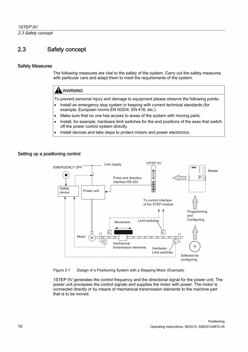
Figure 2-1 Design of a Positioning System with a Stepping Motor (Example)
1STEP 5V generates the control frequency and the directional signal for the power unit. The power unit processes the control signals and supplies the motor with power. The motor is connected directly or by means of mechanical transmission elements to the machine part that is to be moved.
1STEP 5V 2.4 Brief description of how to commission the 1STEP 5V
Positioning Operating Instructions, 06/2010, A5E00124872-05 11
2.4 Brief description of how to commission the 1STEP 5V
Introduction The task of 1STEP 5V is to position a drive at certain predefined targets. Using the example of an incremental run, it guides you to a functioning application in which you get to know and check a traversing job (both hardware and software) of your 1STEP 5V.
Note Note that the power unit must process signals for pulses and direction in accordance with RS 422. Make sure you also adapt the wiring to the products you have chosen.
Prerequisites for the Example The following prerequisites must be fulfilled: You must have put an ET 200S station on an S7 station with a DP master into operation. You must have the following:
– A terminal module TM-E15x24-01 or TM-E15x26-A1 (order number 6ES7 193-4CBx0-0AA0 or 6ES7 193-4CAx0-0AA0)
– A 1STEP 5V (order number 6ES7 138-4DC01-0AB0)
– A stepping motor with the corresponding power unit – The necessary wiring material
1STEP 5V 2.4 Brief description of how to commission the 1STEP 5V
Positioning 12 Operating Instructions, 06/2010, A5E00124872-05
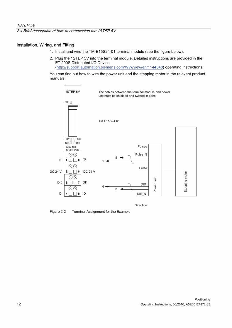
Installation, Wiring, and Fitting 1. Install and wire the TM-E15S24-01 terminal module (see the figure below). 2. Plug the 1STEP 5V into the terminal module. Detailed instructions are provided in the
ET 200S Distributed I/O Device (http://support.automation.siemens.com/WW/view/en/1144348) operating instructions.
You can find out how to wire the power unit and the stepping motor in the relevant product manuals.
Figure 2-2 Terminal Assignment for the Example
1STEP 5V 2.4 Brief description of how to commission the 1STEP 5V
Positioning Operating Instructions, 06/2010, A5E00124872-05 13
Using HW Config to configure with STEP 7 You begin by adapting the hardware configuration to your existing ET 200S station. 1. Open the relevant project in SIMATIC Manager. 2. Open the HW Config configuration table in your project. 3. Select 1STEP in the hardware catalog. The number 6ES7 138-4DC01-0AB0 is displayed
in the infotext. Drag the entry to the slot at which you have mounted your 1STEP 5V. 4. Double-click this number to open the DP Slave Properties dialog box. 5. On the Addresses tab, you will find the addresses of the slot to which you have dragged
the 1STEP 5V. Make a note of these addresses for subsequent programming. 6. The Parameters tab contains the default settings for the 1STEP 5V. Set the "DI0 function"
as an "external STOP". The "Input DI0" has to be set as a "NO contact". 7. Save and compile your configuration, and download the configuration in STOP mode of
the CPU by choosing "PLC -> Download to Module".
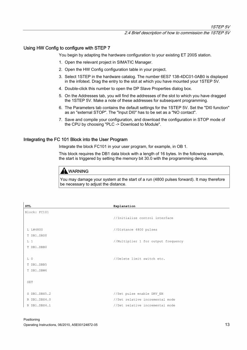
Integrating the FC 101 Block into the User Program Integrate the block FC101 in your user program, for example, in OB 1. This block requires the DB1 data block with a length of 16 bytes. In the following example, the start is triggered by setting the memory bit 30.0 with the programming device.
WARNING You may damage your system at the start of a run (4800 pulses forward). It may therefore be necessary to adjust the distance.
STL Explanation
Block: FC101
//Initialize control interface
L L#4800
T DB1.DBD0
L 1
T DB1.DBB0
//Distance 4800 pulses
//Multiplier 1 for output frequency
L 0
T DB1.DBB5
T DB1.DBW6
//Delete limit switch etc.
SET
S DB1.DBX5.2
R DB1.DBX4.0
R DB1.DBX4.1
//Set pulse enable DRV_EN
//Set relative incremental mode
//Set relative incremental mode
1STEP 5V 2.4 Brief description of how to commission the 1STEP 5V
Positioning 14 Operating Instructions, 06/2010, A5E00124872-05
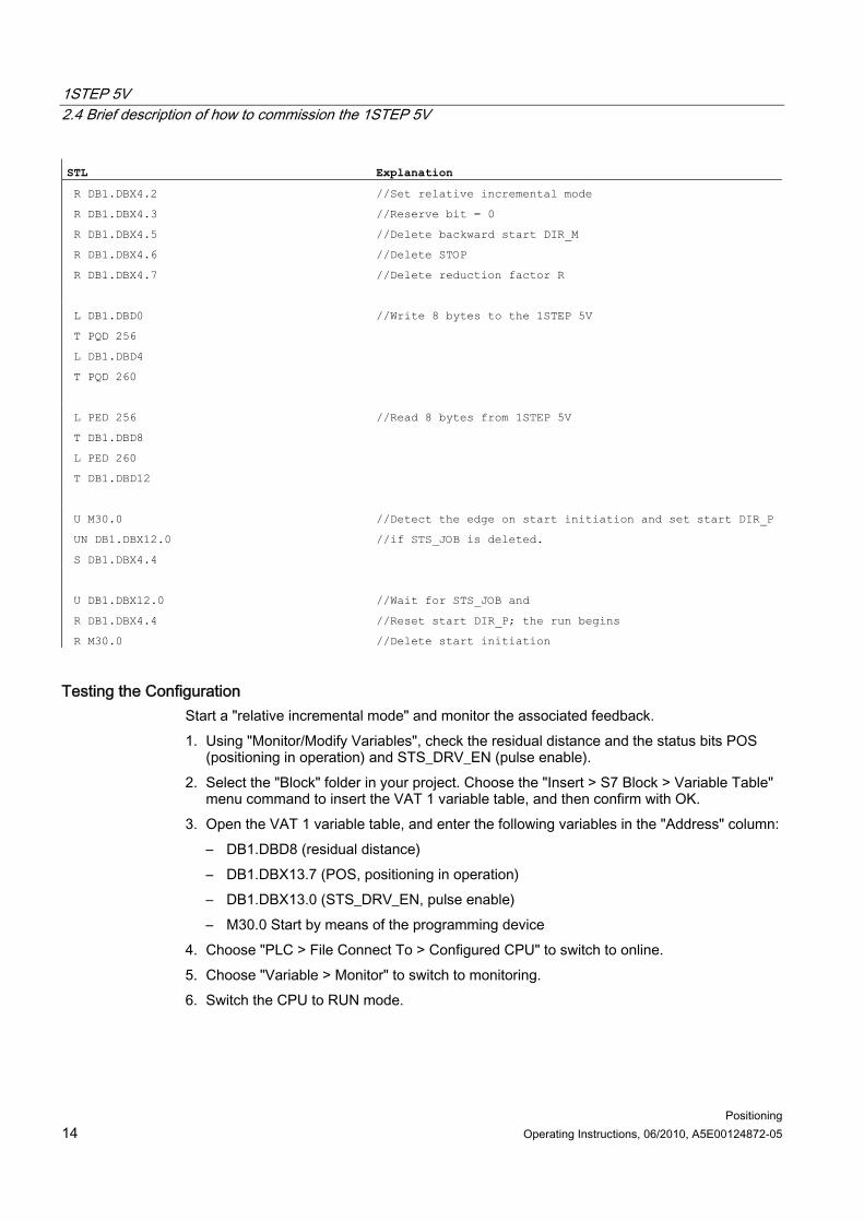
STL Explanation
R DB1.DBX4.2
R DB1.DBX4.3
R DB1.DBX4.5
R DB1.DBX4.6
R DB1.DBX4.7
//Set relative incremental mode
//Reserve bit = 0
//Delete backward start DIR_M
//Delete STOP
//Delete reduction factor R
L DB1.DBD0
T PQD 256
L DB1.DBD4
T PQD 260
//Write 8 bytes to the 1STEP 5V
L PED 256
T DB1.DBD8
L PED 260
T DB1.DBD12
//Read 8 bytes from 1STEP 5V
U M30.0
UN DB1.DBX12.0
S DB1.DBX4.4
//Detect the edge on start initiation and set start DIR_P
//if STS_JOB is deleted.
U DB1.DBX12.0
R DB1.DBX4.4
R M30.0
//Wait for STS_JOB and
//Reset start DIR_P; the run begins
//Delete start initiation
Testing the Configuration Start a "relative incremental mode" and monitor the associated feedback. 1. Using "Monitor/Modify Variables", check the residual distance and the status bits POS
(positioning in operation) and STS_DRV_EN (pulse enable). 2. Select the "Block" folder in your project. Choose the "Insert > S7 Block > Variable Table"
menu command to insert the VAT 1 variable table, and then confirm with OK. 3. Open the VAT 1 variable table, and enter the following variables in the "Address" column:
– DB1.DBD8 (residual distance) – DB1.DBX13.7 (POS, positioning in operation) – DB1.DBX13.0 (STS_DRV_EN, pulse enable) – M30.0 Start by means of the programming device
4. Choose "PLC > File Connect To > Configured CPU" to switch to online. 5. Choose "Variable > Monitor" to switch to monitoring. 6. Switch the CPU to RUN mode.
1STEP 5V 2.4 Brief description of how to commission the 1STEP 5V
Positioning Operating Instructions, 06/2010, A5E00124872-05 15
Result When you switch the CPU to RUN, the following results are obtained: The RDY LED lights up The POS status bit is deleted The STS_DRV_EN status bit is set Start the run by setting memory bit 30.0 ("Variable > Modify >"). The following result is obtained during the run: The POS status bit is set (you can see this by monitoring the variable); that is, the POS
LED lights up. The residual distance is continuously updated. The STS_DRV_EN status bit (pulse enable) is set. The following result is obtained after the run has been completed: The POS status bit is deleted (you can see this by monitoring the variable); that is, the
POS LED is no longer illuminated The residual distance is 0. The STS_DRV_EN status bit (pulse enable) is set.

1STEP 5V 2.5 Terminal Assignment Diagram
Positioning 16 Operating Instructions, 06/2010, A5E00124872-05
2.5 Terminal Assignment Diagram
Wiring rules The cables (terminals 1 and 5 and terminals 4 and 8) to the power unit must be shielded, twisted-pair cables. The shield must be supported at both ends. You use the shield contact element (Order Number: 6ES7 390-5AA00-0AA0).
1STEP 5V 2.5 Terminal Assignment Diagram
Positioning Operating Instructions, 06/2010, A5E00124872-05 17
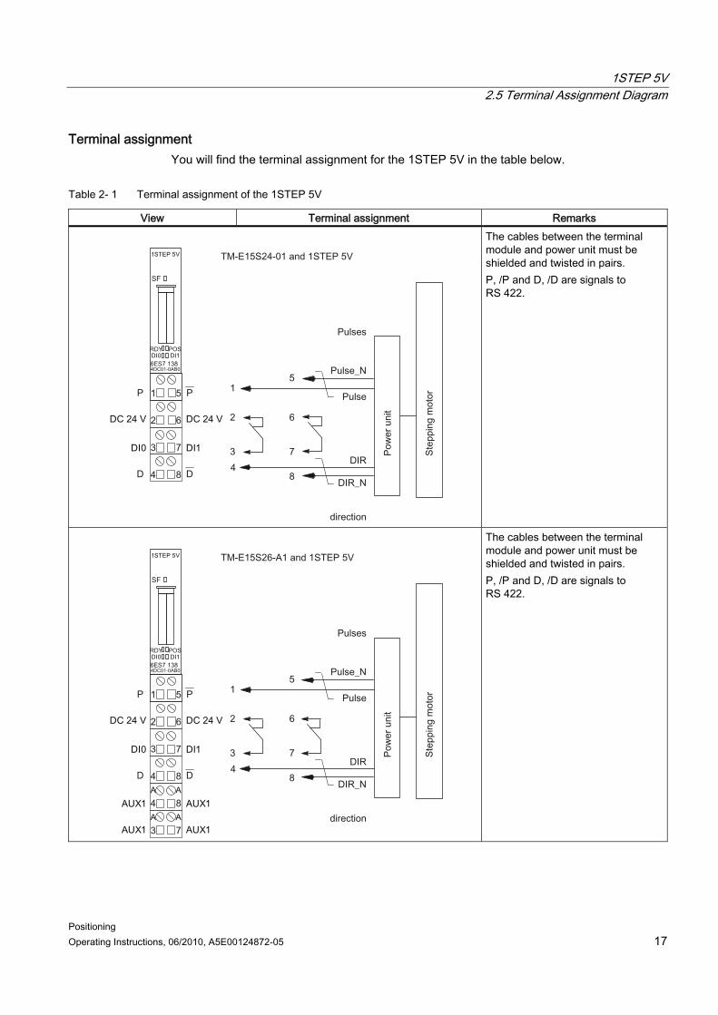
Terminal assignment You will find the terminal assignment for the 1STEP 5V in the table below.
Table 2- 1 Terminal assignment of the 1STEP 5V
View Terminal assignment Remarks
The cables between the terminal module and power unit must be shielded and twisted in pairs. P, /P and D, /D are signals to RS 422.
The cables between the terminal module and power unit must be shielded and twisted in pairs. P, /P and D, /D are signals to RS 422.
1STEP 5V 2.6 Fundamentals of Positioning
Positioning 18 Operating Instructions, 06/2010, A5E00124872-05
2.6 Fundamentals of Positioning
2.6.1 Overview
Introduction The following informs about how the individual components - the electronic module, the power unit, and the motor - affect each other.
Stepping motors Stepping motors are used to position axes. They represent the simple and cost-effective solution for precision positioning tasks in wide performance ranges. A stepping motor shaft turns by a certain angle with every pulse. During rapid pulse sequences, this stepping movement becomes a continuous turning motion.
Power unit for stepping motors The power unit is the link between the 1STEP 5V and the stepping motor. The 1STEP 5V sends RS 422 differential signals for frequency and direction. These signals are converted in the power unit into motor currents that control the movements of the motor with a very high degree of precision.
1STEP 5V The 1STEP 5V generates pulses and a directional signal for the power units of stepping motors. The number of pulses emitted determines the distance traversed. The pulse frequency determines the velocity. The change in the pulse frequency per time unit (second) is a measure for the acceleration or deceleration. 1STEP 5V is influenced by its parameters and settings.
1STEP 5V 2.6 Fundamentals of Positioning
Positioning Operating Instructions, 06/2010, A5E00124872-05 19
2.6.2 Parameters and Settings
Required Information To ensure optimum interplay between the individual components, you must provide the 1STEP 5V with information: One time: during parameter configuration using your configuration software
– Base Frequency Fb:(see section "Setting the Base Frequency (Page 25)") – Multiplier n for setting the start-stop frequency Fss(see section "Traversal curve of the
1STEP 5V (Page 22)") – Multiplier i for setting the acceleration/delay (see section "Traversal curve of the
1STEP 5V (Page 22)") – Function and behavior of the digital inputs (see section "Behavior of the Digital Inputs
(Page 42)") – Traversing range (see section "Axis type and traversing range (Page 38)")
In operation: movement of the motor by means of a traversing job in your user program – Multiplier G for the velocity/output frequency Fa(see section "Traversal curve of the
1STEP 5V (Page 22)") – Reduction factor R (see section "Setting the Base Frequency (Page 25)") – Distance, position or frequency – Operating mode – Direction specification (traversing job) to the start
In operation: to adjust to different load conditions as a parameter assignment request in your user program – Base Frequency Fb:(see section "Setting the Base Frequency (Page 25)") – Multiplier n for setting the start-stop frequency Fss(see section "Traversal curve of the
1STEP 5V (Page 22)") – Multiplier i for setting the acceleration/delay (see section "Traversal curve of the
1STEP 5V (Page 22)")
1STEP 5V 2.6 Fundamentals of Positioning
Positioning 20 Operating Instructions, 06/2010, A5E00124872-05
2.6.3 Traversal curve of the 1STEP 5V
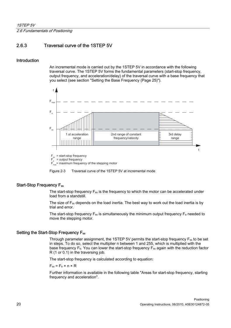
Introduction An incremental mode is carried out by the 1STEP 5V in accordance with the following traversal curve. The 1STEP 5V forms the fundamental parameters (start-stop frequency, output frequency, and acceleration/delay) of the traversal curve with a base frequency that you select (see section "Setting the Base Frequency (Page 25)").
Figure 2-3 Traversal curve of the 1STEP 5V at incremental mode
Start-Stop Frequency Fss The start-stop frequency Fss is the frequency to which the motor can be accelerated under load from a standstill. The size of Fss depends on the load inertia. The best way to work out the load inertia is by trial and error. The start-stop frequency Fss is simultaneously the minimum output frequency Fa needed to move the stepping motor.
Setting the Start-Stop Frequency Fss Through parameter assignment, the 1STEP 5V permits the start-stop frequency Fss to be set in steps. To do so, select the multiplier n between 1 and 255, which is multiplied with the base frequency Fb. You can lower the start-stop frequency Fss again with the reduction factor R (1 or 0.1) in the traversing job. The start-stop frequency is calculated according to equation: Fss = Fb × n × R Further information is available in the following table "Areas for start-stop frequency, starting frequency and acceleration".
1STEP 5V 2.6 Fundamentals of Positioning
Positioning Operating Instructions, 06/2010, A5E00124872-05 21
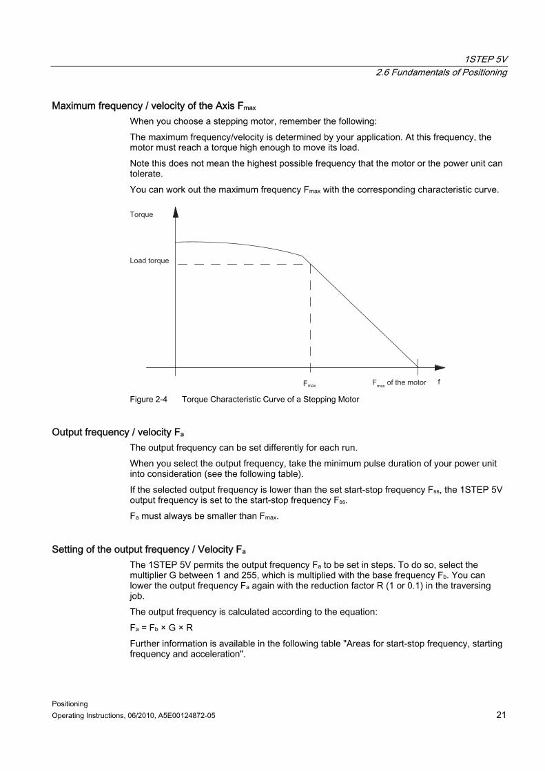
Maximum frequency / velocity of the Axis Fmax When you choose a stepping motor, remember the following: The maximum frequency/velocity is determined by your application. At this frequency, the motor must reach a torque high enough to move its load. Note this does not mean the highest possible frequency that the motor or the power unit can tolerate. You can work out the maximum frequency Fmax with the corresponding characteristic curve.
Figure 2-4 Torque Characteristic Curve of a Stepping Motor
Output frequency / velocity Fa The output frequency can be set differently for each run. When you select the output frequency, take the minimum pulse duration of your power unit into consideration (see the following table). If the selected output frequency is lower than the set start-stop frequency Fss, the 1STEP 5V output frequency is set to the start-stop frequency Fss. Fa must always be smaller than Fmax.
Setting of the output frequency / Velocity Fa The 1STEP 5V permits the output frequency Fa to be set in steps. To do so, select the multiplier G between 1 and 255, which is multiplied with the base frequency Fb. You can lower the output frequency Fa again with the reduction factor R (1 or 0.1) in the traversing job. The output frequency is calculated according to the equation: Fa = Fb × G × R Further information is available in the following table "Areas for start-stop frequency, starting frequency and acceleration".
1STEP 5V 2.6 Fundamentals of Positioning
Positioning 22 Operating Instructions, 06/2010, A5E00124872-05
Acceleration / delay a The maximum permitted acceleration / delay depends on the load to be moved. The motor must reach a torque high enough to accelerate or delay the load without loss of step. Depending on the application, you must also take into account additional criteria for setting the acceleration/delay, such as smooth starting and stopping.
Setting the acceleration / delay a Through parameter assignment, the 1STEP 5V permits the acceleration / delay to be set in steps by means of the multiplier i. During the acceleration phase, the frequency is increased continuously starting from the start-stop frequency Fss until the output frequency Fa has been reached. The time interval for the continuous increase in frequency can be set in steps. To do so you select a multiplier i between 1 and 255. In the delay phase, the output frequency is reduced in the same way. You can lower the acceleration / delay a again with the reduction factor R (1 or 0.1) in the traversing job. The acceleration / deceleration is calculated according to the equation: a = Fb × R / (i × 0.128 ms) Further information is available in the following table "Areas for start-stop frequency, starting frequency and acceleration".
1STEP 5V 2.6 Fundamentals of Positioning
Positioning Operating Instructions, 06/2010, A5E00124872-05 23
2.6.4 Setting the Base Frequency
Introduction Through parameter assignment, the 1STEP 5V permits the base frequency to be set in steps. The base frequency sets the range for the start-stop frequency, the output frequency, and the acceleration.
Procedure 1. Depending on the priority of your requirements select a suitable range either of the start-
stop frequency Fss and of the starting frequency Fa or of the acceleration a from the following table in accordance with the following criteria: – Range for the start-stop frequency Fss,
for example, for starting and stopping as soon as possible – Range for the output frequency Fa,
for example, for a velocity setting that is as precise as possible – Range for the acceleration a,
for example, for the fastest possible positioning operations 2. Use the table to determine the base frequency Fb.
To optimize the base frequency Fb, proceed as follows: 3. Check whether the other corresponding values meet your requirements. If necessary,
select another base frequency Fb, which meets your requirements better. 4. Define the multipliers required to set the output frequency Fa, the acceleration/delay a,
and the start-stop frequency Fss. 5. Determine the corresponding reduction factor R from the table.
1STEP 5V 2.6 Fundamentals of Positioning
Positioning 24 Operating Instructions, 06/2010, A5E00124872-05
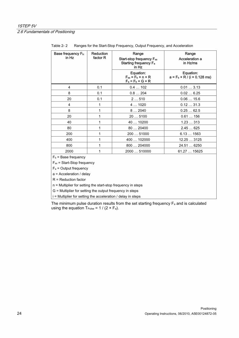
Table 2- 2 Ranges for the Start-Stop Frequency, Output Frequency, and Acceleration
Range Start-stop frequency Fss
Starting frequency Fa in Hz
Range Acceleration a
in Hz/ms
Base frequency Fb: in Hz
Reduction factor R
Equation: Fss = Fb × n × R Fa = Fb × G × R
Equation: a = Fb × R / (i × 0.128 ms)
4 0.1 0.4 … 102 0.01 … 3.13 8 0.1 0.8 … 204 0.02 … 6.25 20 0.1 2 … 510 0.06 … 15.6 4 1 4 … 1020 0.12 … 31.3 8 1 8 … 2040 0.25 … 62.5 20 1 20 … 5100 0.61 … 156 40 1 40 … 10200 1.23 … 313 80 1 80 … 20400 2.45 … 625
200 1 200 … 51000 6.13 … 1563 400 1 400 … 102000 12.25 … 3125 800 1 800 … 204000 24.51 … 6250
2000 1 2000 … 510000 61.27 … 15625 Fb = Base frequency Fss = Start-Stop frequency Fa = Output frequency a = Acceleration / delay R = Reduction factor n = Multiplier for setting the start-stop frequency in steps G = Multiplier for setting the output frequency in steps i = Multiplier for setting the acceleration / delay in steps
The minimum pulse duration results from the set starting frequency Fa and is calculated using the equation TPulse = 1 / (2 × Fa).
1STEP 5V 2.7 Functions of the 1STEP 5V
Positioning Operating Instructions, 06/2010, A5E00124872-05 25
2.7 Functions of the 1STEP 5V
2.7.1 Overview
Introduction The task of the 1STEP 5V is to position a drive on certain predefined targets (incremental modes) and to travel continuously with specifiable frequencies (speed-control mode). The following functions are available to you to this purpose: Reference point approach: The axis is synchronized to a reference point Set home position: A value is assigned to the current position. Relative incremental mode (relative positioning): The axis is moved by a predefined
distance. Absolute incremental mode (absolute positioning): The axis is traveled to a predefined
position. Speed-control mode: The drive is moved with a speed that can be specified flexibly
(pulse frequency). Hold traversing job Changing Parameters during Operation For information on the functions, refer to the section Assignment of the Feedback and Control Interfaces (Page 49)
1STEP 5V 2.7 Functions of the 1STEP 5V
Positioning 26 Operating Instructions, 06/2010, A5E00124872-05
2.7.2 Search for Reference
Description of the function The home position marks the point of reference of your drive system (reference cam) for the following traversing jobs. You can determine the home position by, for example, installing an initiator on the reference cam and connecting it to the DI1 digital input. The 1STEP 5V ensures the reference point can be reproduced accurately in that it is always approached from the same direction. You can specify this direction by always starting the search for reference in the same direction.
Traversing job for reference point approach The traversing job contains the following information: Multiplier G for the velocity/output frequency Fa Reduction factor R for the assigned parameters base frequency Fb Reference point position Mode = 1 for reference point approach Stop at reference cam (see section "Hold traversing job (Page 36)") Direction selection as Start (see section Assignment of the Feedback and Control
Interfaces (Page 49))
Note The 1STEP 5V checks the set position for limits (minimum 0 and maximum 16777215). The full-scale value can be configured.
Note If you have configured the behavior of the digital input DI1 (7) as a "Reference switch and limit switch" (see section "Behavior of the Digital Inputs (Page 42)"), the 1STEP 5V automatically selects the starting direction toward the limit switch, irrespective of the direction specified in the traversing job.
Status bit SYNC The SYNC status bit informs you that the axis has been synchronized, that is, after the correct reference point approach, this status bit is set and deleted during the run. The SYNC status bit is deleted After parameter assignment of your ET 200S station After deletion of the pulse enable After a CPU-/Master-STOP In these cases it is advisable to carry out a search for reference.

1STEP 5V 2.7 Functions of the 1STEP 5V
Positioning Operating Instructions, 06/2010, A5E00124872-05 27
POS and POS_RCD status bits While reference point approach is active, it is indicated by the set POS feedback bit. On completion of a reference point approach, the set POS_RCD feedback bit indicates that the position has been reached. If the reference point approach is interrupted, the POS_RCD feedback bit remains reset.
Residual distance, position, frequency The residual distance reported is irrelevant during the reference point approach (see section "Assignment of the Feedback and Control Interfaces (Page 49)").
Note In order for the 1STEP 5V to approach the home position with repeated precision, the period duration of the start-stop frequency has to be greater than the runtime of a single step from the 1STEP 5V to the stepping motor and via the reference cam back to 1STEP 5V. See also "Input delay of the digital inputs" in the section "Technical Specifications (Page 59)". When stopping at the reference cam or at one of the limit switches during the acceleration phase, the 1STEP 5V continues to send pulses for a maximum of 50 ms at the frequency already reached before it starts braking. This avoids abrupt changes in frequency, which can lead to step losses.
1STEP 5V 2.7 Functions of the 1STEP 5V
Positioning 28 Operating Instructions, 06/2010, A5E00124872-05
2.7.3 Sequence of Execution of the Search for Reference
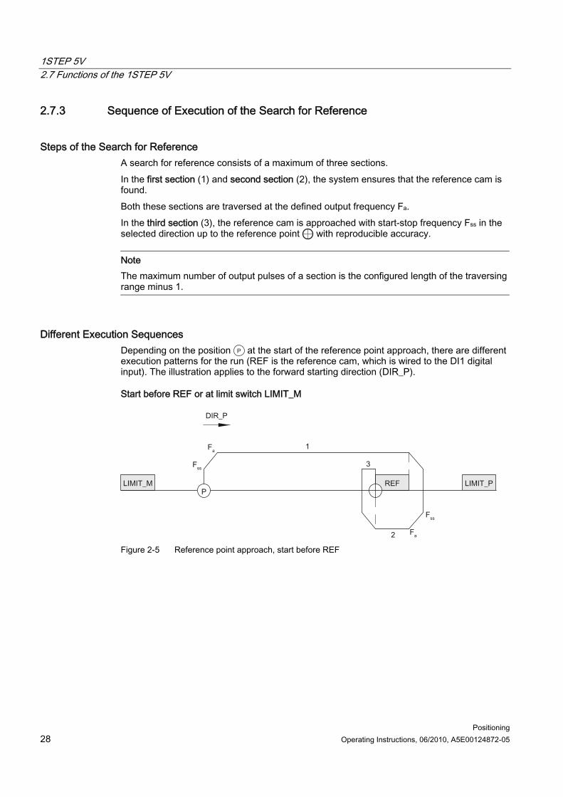
Steps of the Search for Reference A search for reference consists of a maximum of three sections. In the first section (1) and second section (2), the system ensures that the reference cam is found. Both these sections are traversed at the defined output frequency Fa. In the third section (3), the reference cam is approached with start-stop frequency Fss in the selected direction up to the reference point with reproducible accuracy.
Note The maximum number of output pulses of a section is the configured length of the traversing range minus 1.
Different Execution Sequences Depending on the position at the start of the reference point approach, there are different execution patterns for the run (REF is the reference cam, which is wired to the DI1 digital input). The illustration applies to the forward starting direction (DIR_P).
Start before REF or at limit switch LIMIT_M
Figure 2-5 Reference point approach, start before REF
1STEP 5V 2.7 Functions of the 1STEP 5V
Positioning Operating Instructions, 06/2010, A5E00124872-05 29
Start after REF
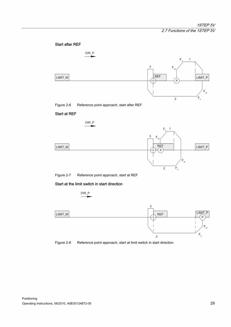
Figure 2-6 Reference point approach, start after REF
Start at REF
Figure 2-7 Reference point approach, start at REF
Start at the limit switch in start direction
Figure 2-8 Reference point approach, start at limit switch in start direction
1STEP 5V 2.7 Functions of the 1STEP 5V
Positioning 30 Operating Instructions, 06/2010, A5E00124872-05
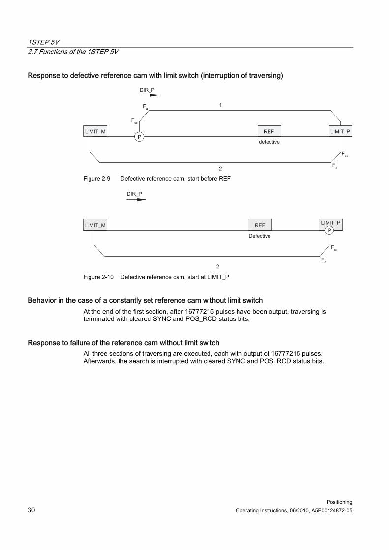
Response to defective reference cam with limit switch (interruption of traversing)
Figure 2-9 Defective reference cam, start before REF
Figure 2-10 Defective reference cam, start at LIMIT_P
Behavior in the case of a constantly set reference cam without limit switch At the end of the first section, after 16777215 pulses have been output, traversing is terminated with cleared SYNC and POS_RCD status bits.
Response to failure of the reference cam without limit switch All three sections of traversing are executed, each with output of 16777215 pulses. Afterwards, the search is interrupted with cleared SYNC and POS_RCD status bits.
1STEP 5V 2.7 Functions of the 1STEP 5V
Positioning Operating Instructions, 06/2010, A5E00124872-05 31
2.7.4 Set home position
Description of the function The home position marks the reference point of your drive system which the subsequent absolute incremental modes and the position value in the feedback interface reference. You define the home position by specifying the absolute position value for the current position of the stepping motor.
Job for setting the home position A job for setting the home position is a virtual job without traversing movement. It contains the following information: Position of the home position Mode = 4 for setting home position Any direction specification as start (see section "Assignment of the Feedback and Control
Interfaces (Page 49)")
Note The 1STEP 5V checks the set position for limits (minimum 0 and maximum 16777215). The full-scale value can be configured.
Feedback messages Correct execution of the job is indicated by the set SYNC and POS_RCD feedback bits.
1STEP 5V 2.7 Functions of the 1STEP 5V
Positioning 32 Operating Instructions, 06/2010, A5E00124872-05
2.7.5 Relative incremental mode (relative positioning)
Description of the function You can use the relative incremental mode to move the stepping motor a defined distance and thus approach a specified position. You can determine the direction of traversing and the velocity at the start.
Traversing job for relative incremental mode The traversing job contains the following information: Distance (number of pulses to be emitted) Multiplier G for the velocity/output frequency Fa Reduction factor R for the assigned parameters base frequency Fb Mode = 0 for incremental mode, relative Stop at reference cam (see section "Hold traversing job (Page 36)") Direction selection as start (see section "Assignment of the Feedback and Control
Interfaces (Page 49)")
Note The 1STEP 5V checks the specified distance for limits (minimum 1 and maximum 16777215 pulses). The distance to the limit switch is not checked by the 1STEP 5V. Traversing is stopped at the latest when the limit switch is reached.
Feedback messages The POS_RCD feedback bit is reset at the beginning of incremental mode. While the incremental mode is active, it is indicated by the set POS feedback bit. After incremental mode has been correctly executed, the set POS_RCD feedback bit indicates that the position has been reached. If the incremental mode is interrupted, the POS_RCD feedback bit remains reset. After incremental mode has been stopped, the distance still to be traversed is displayed if the feedback value is set to "Residual distance (see section "Assignment of the Feedback and Control Interfaces (Page 49)").
1STEP 5V 2.7 Functions of the 1STEP 5V
Positioning Operating Instructions, 06/2010, A5E00124872-05 33
2.7.6 Absolute incremental mode (absolute positioning)
Description of the function You can use the absolute mode to move the stepping motor to a defined position and thus approach a specified position. The velocity is specified at the start. The direction and the distance of traversing are determined automatically by the 1STEP 5V on the basis of the starting position (actual position value). You can also specify the direction for a modulo axis.
Note If you set Forward start and Backward start (DIR_P and DIR_M) simultaneously at a modulo axis, the 1STEP 5V then automatically selects the shortest distance to reach the target position (see section "Axis type and traversing range (Page 38)").
Traversing job for absolute incremental mode The traversing job contains the following information: Target position Multiplier G for the velocity/output frequency Fa Reduction factor R for the assigned parameters base frequency Fb Mode = 2 for incremental mode Any direction specification as start (see section "Assignment of the Feedback and Control
Interfaces (Page 49)")
Note The 1STEP 5V checks the set position for limits (minimum 0 and maximum 16777215). The full-scale value can be configured. The traversing job is only executed if you have determined or specified the position of the home position beforehand (the SYNC bit has to be set, see section "Search for Reference (Page 28)" or "Set home position (Page 31)"). The control signal "Hold at reference cam" is not taken into consideration (see section "Assignment of the Feedback and Control Interfaces (Page 49)").
Feedback messages The POS_RCD feedback bit is reset at the beginning of incremental mode. While the incremental mode is active, it is indicated by the set POS feedback bit. After incremental mode has been correctly executed, the set POS_RCD feedback bit indicates that the position has been reached. If the incremental mode is interrupted, the POS_RCD feedback bit remains reset. After incremental mode has been stopped, the distance still to be traversed is displayed if the feedback value is set to "Residual distance (see section "Assignment of the Feedback and Control Interfaces (Page 49)").
1STEP 5V 2.7 Functions of the 1STEP 5V
Positioning 34 Operating Instructions, 06/2010, A5E00124872-05
2.7.7 Speed-control mode
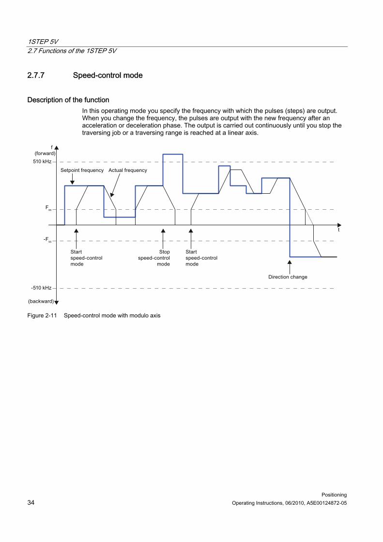
Description of the function In this operating mode you specify the frequency with which the pulses (steps) are output. When you change the frequency, the pulses are output with the new frequency after an acceleration or deceleration phase. The output is carried out continuously until you stop the traversing job or a traversing range is reached at a linear axis.
Figure 2-11 Speed-control mode with modulo axis
1STEP 5V 2.7 Functions of the 1STEP 5V
Positioning Operating Instructions, 06/2010, A5E00124872-05 35
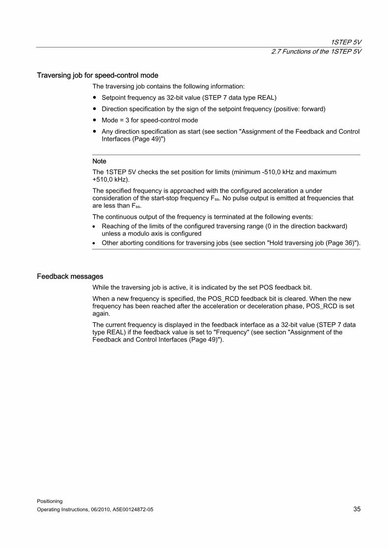
Traversing job for speed-control mode The traversing job contains the following information: Setpoint frequency as 32-bit value (STEP 7 data type REAL) Direction specification by the sign of the setpoint frequency (positive: forward) Mode = 3 for speed-control mode Any direction specification as start (see section "Assignment of the Feedback and Control
Interfaces (Page 49)")
Note The 1STEP 5V checks the set position for limits (minimum -510,0 kHz and maximum +510,0 kHz). The specified frequency is approached with the configured acceleration a under consideration of the start-stop frequency Fss. No pulse output is emitted at frequencies that are less than Fss. The continuous output of the frequency is terminated at the following events: Reaching of the limits of the configured traversing range (0 in the direction backward)
unless a modulo axis is configured Other aborting conditions for traversing jobs (see section "Hold traversing job (Page 36)").
Feedback messages While the traversing job is active, it is indicated by the set POS feedback bit. When a new frequency is specified, the POS_RCD feedback bit is cleared. When the new frequency has been reached after the acceleration or deceleration phase, POS_RCD is set again. The current frequency is displayed in the feedback interface as a 32-bit value (STEP 7 data type REAL) if the feedback value is set to "Frequency" (see section "Assignment of the Feedback and Control Interfaces (Page 49)").
1STEP 5V 2.7 Functions of the 1STEP 5V
Positioning 36 Operating Instructions, 06/2010, A5E00124872-05
2.7.8 Hold traversing job
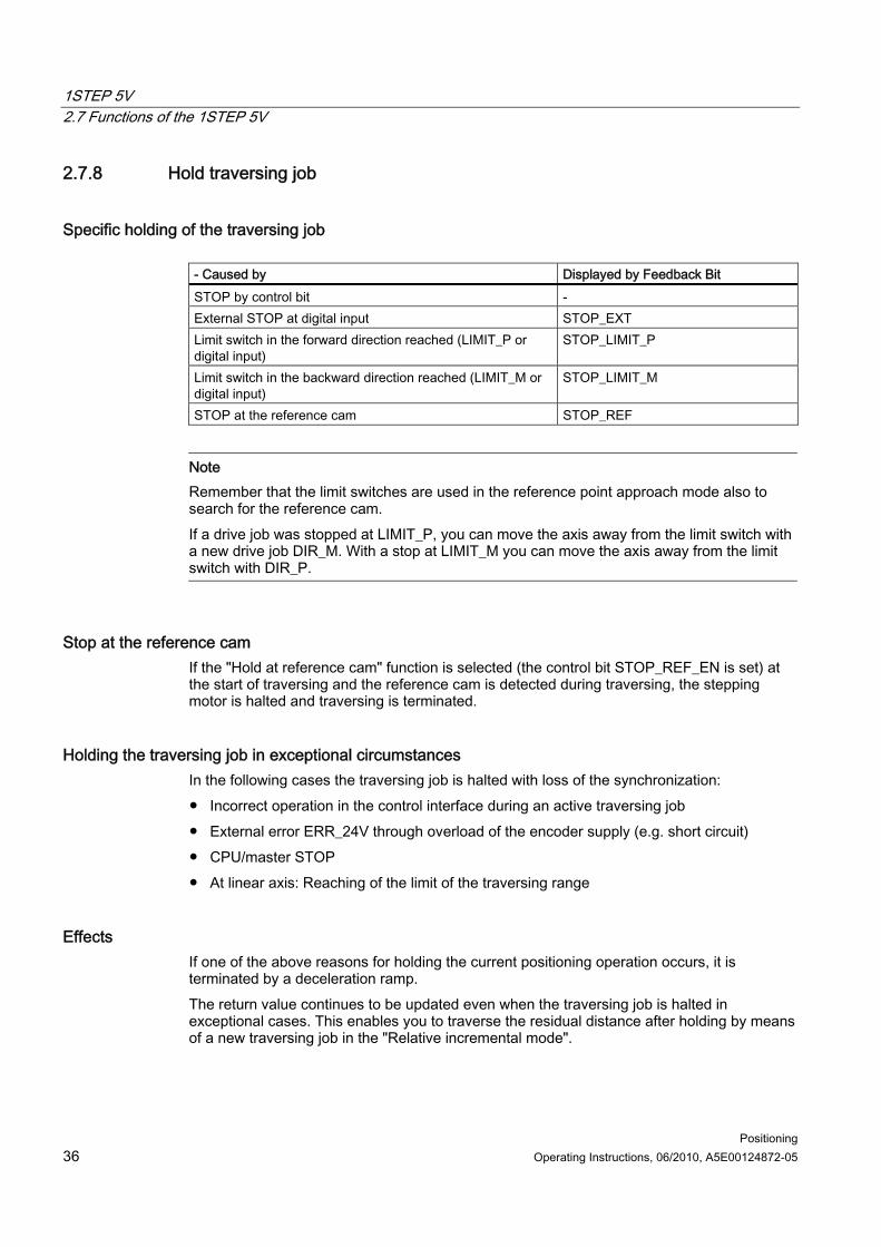
Specific holding of the traversing job - Caused by Displayed by Feedback Bit STOP by control bit - External STOP at digital input STOP_EXT Limit switch in the forward direction reached (LIMIT_P or digital input)
STOP_LIMIT_P
Limit switch in the backward direction reached (LIMIT_M or digital input)
STOP_LIMIT_M
STOP at the reference cam STOP_REF
Note Remember that the limit switches are used in the reference point approach mode also to search for the reference cam. If a drive job was stopped at LIMIT_P, you can move the axis away from the limit switch with a new drive job DIR_M. With a stop at LIMIT_M you can move the axis away from the limit switch with DIR_P.
Stop at the reference cam If the "Hold at reference cam" function is selected (the control bit STOP_REF_EN is set) at the start of traversing and the reference cam is detected during traversing, the stepping motor is halted and traversing is terminated.
Holding the traversing job in exceptional circumstances In the following cases the traversing job is halted with loss of the synchronization: Incorrect operation in the control interface during an active traversing job External error ERR_24V through overload of the encoder supply (e.g. short circuit) CPU/master STOP At linear axis: Reaching of the limit of the traversing range
Effects If one of the above reasons for holding the current positioning operation occurs, it is terminated by a deceleration ramp. The return value continues to be updated even when the traversing job is halted in exceptional cases. This enables you to traverse the residual distance after holding by means of a new traversing job in the "Relative incremental mode".
1STEP 5V 2.7 Functions of the 1STEP 5V
Positioning Operating Instructions, 06/2010, A5E00124872-05 37
Limit Switches and External STOP By assigning parameters, you can choose to wire normally open or normally closed contacts for the external STOP and the limit switches. Normally closed contact means: The external STOP and the effect of the limit switches
are triggered by a 0 signal. When the limit switches are reached, delete the associated control bit.
Normally open contact means: The external STOP and the effect of the limit switches are triggered by a 1 signal. When the limit switches are reached, set the associated control bit.
Note In case of holding during the acceleration phase the 1STEP 5V continues to send pulses for a maximum of 50 ms at the frequency already reached before it starts braking. This avoids abrupt changes in frequency, which can lead to step losses.
1STEP 5V 2.7 Functions of the 1STEP 5V
Positioning 38 Operating Instructions, 06/2010, A5E00124872-05
2.7.9 Axis type and traversing range
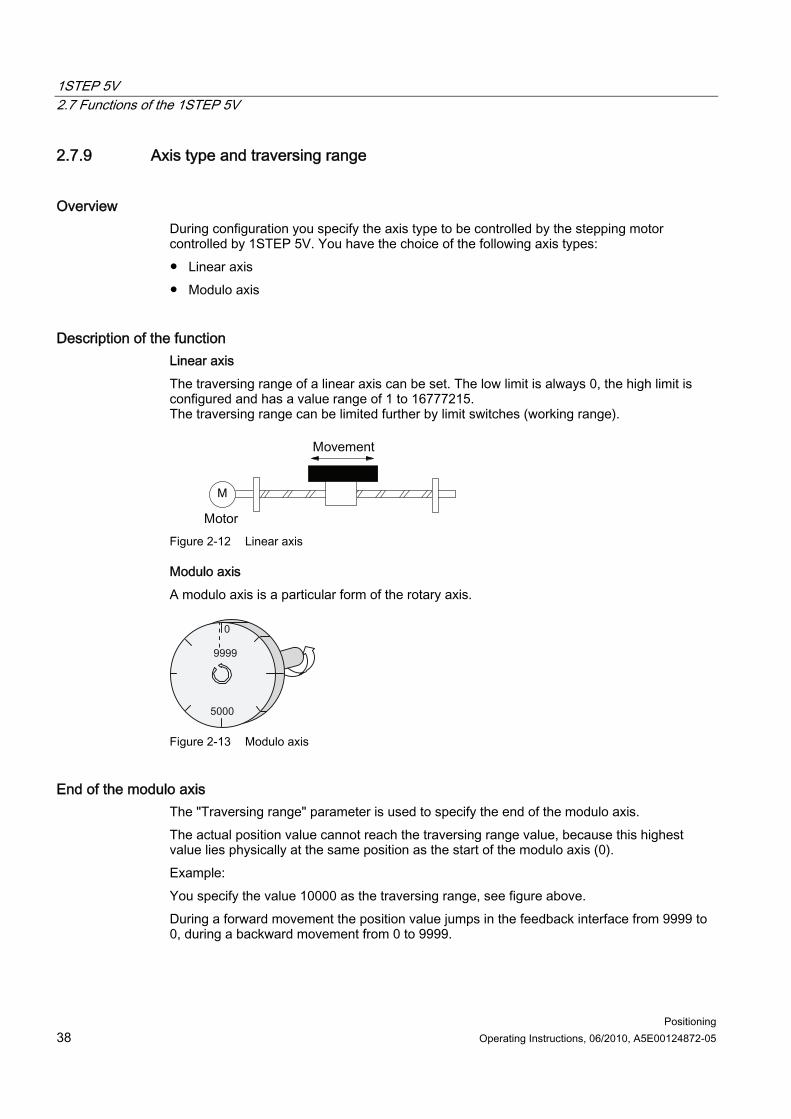
Overview During configuration you specify the axis type to be controlled by the stepping motor controlled by 1STEP 5V. You have the choice of the following axis types: Linear axis Modulo axis
Description of the function Linear axis The traversing range of a linear axis can be set. The low limit is always 0, the high limit is configured and has a value range of 1 to 16777215. The traversing range can be limited further by limit switches (working range).
M
Figure 2-12 Linear axis
Modulo axis A modulo axis is a particular form of the rotary axis.
Figure 2-13 Modulo axis
End of the modulo axis The "Traversing range" parameter is used to specify the end of the modulo axis. The actual position value cannot reach the traversing range value, because this highest value lies physically at the same position as the start of the modulo axis (0). Example: You specify the value 10000 as the traversing range, see figure above. During a forward movement the position value jumps in the feedback interface from 9999 to 0, during a backward movement from 0 to 9999.
1STEP 5V 2.7 Functions of the 1STEP 5V
Positioning Operating Instructions, 06/2010, A5E00124872-05 39
Reference point approach If you have selected the modulo axis during the configuration and have assigned a reference cam to your drive system, you can carry out a reference point approach (see section "Search for Reference (Page 28)"). Traversing is aborted unsuccessfully if the reference cam is not found after the output of a number of pulses that corresponds to the configured traversing range. The SYNC and POS_RCD status bits then remain deleted.
Set home position You may only specify values from 0 to the end of the configured end of the traversing range – 1 for the position of the home position.
Relative positioning The end of the traversing range (end of the modulo axis) may be exceeded in both directions.
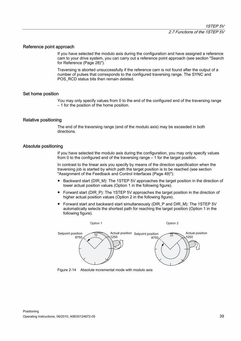
Absolute positioning If you have selected the modulo axis during the configuration, you may only specify values from 0 to the configured end of the traversing range – 1 for the target position. In contrast to the linear axis you specify by means of the direction specification when the traversing job is started by which path the target position is to be reached (see section "Assignment of the Feedback and Control Interfaces (Page 49)"): Backward start (DIR_M): The 1STEP 5V approaches the target position in the direction of
lower actual position values (Option 1 in the following figure). Forward start (DIR_P): The 1STEP 5V approaches the target position in the direction of
higher actual position values (Option 2 in the following figure). Forward start and backward start simultaneously (DIR_P and DIR_M): The 1STEP 5V
automatically selects the shortest path for reaching the target position (Option 1 in the following figure).
Figure 2-14 Absolute incremental mode with modulo axis
1STEP 5V 2.7 Functions of the 1STEP 5V
Positioning 40 Operating Instructions, 06/2010, A5E00124872-05
2.7.10 Pulse Enable
Description of the function Pulse enable permits the output of pulses from the 1STEP 5V to the power unit. A run is not possible without pulse enable.
Activating Pulse Enable You can activate pulse enable by one of the following methods: Through the digital input DI0 when "Function DI0" is configured as an external pulse
enable (see section "Behavior of the Digital Inputs (Page 42)") or Through the control bit DRV_EN when the "Function DI0" is configured as an external
STOP or limit switch forward or backward (see section "Behavior of the Digital Inputs (Page 42)")
You can recognize the assigned pulse enable through the fact that The RDY LED at the 1STEP 5V light up in case of correct configuration. The STS_DRV_EN feedback bit is set.
Deleting the Pulse Enable Deleting the pulse enable during a run terminates the run immediately because no more pulses are emitted to the power unit. The residual distance and actual position value are no longer valid. The synchronization of the axis by means of the reference point is lost. The SYNC feedback bit and the RDY LED are deleted. Deleting the pulse enable when the motor is at standstill deletes the SYNC feedback bit and the RDY LED. In this case it may be necessary to carry out a reference point approach.
1STEP 5V 2.7 Functions of the 1STEP 5V
Positioning Operating Instructions, 06/2010, A5E00124872-05 41
2.7.11 Changing Parameters during Operation
Introduction You can change several of the 1STEP 5V parameters during operation without having to reassign the parameters of the whole ET 200S station.
Parameters That Can Be Changed The following parameters can be changed: Base Frequency Fb: Multiplier n for start-stop frequency Fss Multiplier i for acceleration / delay Feedback value in the feedback interface When you start changing parameters by means of the C_PAR control bit, the parameters are checked for permitted values (see section "Parameter assignment (Page 45)"). If you have set invalid values, the ERR_JOB feedback bit is set. Only the feedback bits for the ERR_JOB and STS_JOB job processing are affected by the configuration job.
1STEP 5V 2.7 Functions of the 1STEP 5V
Positioning 42 Operating Instructions, 06/2010, A5E00124872-05
2.7.12 Behavior of the Digital Inputs
Introduction You can configure the function and the behavior (active level) of the digital inputs DI0 (3) and DI1 (7). These parameters cannot be changed using the user program.
Digital input DI0 (3) You can configure the function of the digital input DI0 (3) as: An external pulse enable An external STOP Limit switch in the forward direction Limit switch in the backward direction You can also configure the behavior of the digital input DI0 (3) as: Normally closed contact Normally open contact
Digital input DI0 (3) as an external pulse enable The input must be put into operation (activated). If the input is set and the configuration correct, the 1STEP 5V is ready for operation (see section "Pulse Enable (Page 40)").
Digital input DI0 (3) as an external STOP With this input function, you can halt a current transverse job by means of an external signal (see section "Hold traversing job (Page 36)").
Digital input DI0 (3) as a limit switch in the direction forward or backward With these input functions, you limit the traversing range in the forward or backward direction through an external signal. The signal has the same effect as one of the two control bits LIMIT_P or LIMIT_M in the control interface (see section "Assignment of the Feedback and Control Interfaces (Page 49)").
1STEP 5V 2.7 Functions of the 1STEP 5V
Positioning Operating Instructions, 06/2010, A5E00124872-05 43
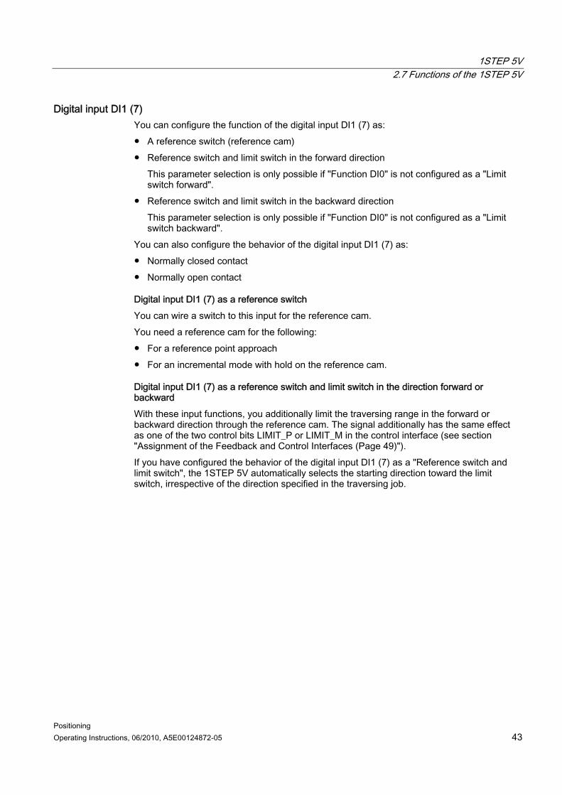
Digital input DI1 (7) You can configure the function of the digital input DI1 (7) as: A reference switch (reference cam) Reference switch and limit switch in the forward direction
This parameter selection is only possible if "Function DI0" is not configured as a "Limit switch forward".
Reference switch and limit switch in the backward direction This parameter selection is only possible if "Function DI0" is not configured as a "Limit switch backward".
You can also configure the behavior of the digital input DI1 (7) as: Normally closed contact Normally open contact
Digital input DI1 (7) as a reference switch You can wire a switch to this input for the reference cam. You need a reference cam for the following: For a reference point approach For an incremental mode with hold on the reference cam.
Digital input DI1 (7) as a reference switch and limit switch in the direction forward or backward With these input functions, you additionally limit the traversing range in the forward or backward direction through the reference cam. The signal additionally has the same effect as one of the two control bits LIMIT_P or LIMIT_M in the control interface (see section "Assignment of the Feedback and Control Interfaces (Page 49)"). If you have configured the behavior of the digital input DI1 (7) as a "Reference switch and limit switch", the 1STEP 5V automatically selects the starting direction toward the limit switch, irrespective of the direction specified in the traversing job.
1STEP 5V 2.7 Functions of the 1STEP 5V
Positioning 44 Operating Instructions, 06/2010, A5E00124872-05
2.7.13 Behavior at CPU-Master-STOP
Introduction The 1STEP 5V detects the CPU/master STOP. It reacts to this by stopping the active traversing job (see section "Hold traversing job (Page 36)").
Exiting the CPU-Master-STOP Status ET 200S station 1STEP 5V Without reconfiguration of the ET 200S station The feedback interface of the 1STEP 5V remains
current. The values changed by means of parameter
assignment job are maintained. If a control bit was set (DIR_P, DIR_M, C_PAR)
when the CPU/master STOP occurred, the bits STS_JOB and ERR_JOB are set when the CPU/master STOP status is exited. Delete the control bit. Traversing / the parameter assignment job is not executed. You can then start a new traversing by means of the control bit.
After the delay ramp, the pulse enable, the RDY LED, and the SYNC status bit are deleted.
With reconfiguration of the ET 200S station Information on previous searches and parameter assignment jobs is reset.
If pulse enable was activated by means of the control bit DRV_EN at the time of the CPU/master STOP, the pulse enable, the RDY LED, and the SYNC status bit are deleted after the delay ramp.
Reconfiguration of the ET 200S station Reconfiguration of the ET 200S station is carried out by your CPU/ DP master at: POWER ON of the CPU / DP master POWER ON of the IM 151 / IM 151 FO After failure of the DP transmission Upon loading changed parameters or configuration of the ET 200S station into the CPU /
DP master When the 1STEP 5V is plugged Upon power on or inserting of the appropriate power module
See also Pulse Enable (Page 40)
1STEP 5V 2.8 Parameter assignment
Positioning Operating Instructions, 06/2010, A5E00124872-05 45
2.8 Parameter assignment
Setting the Parameters You set the parameters for the 1STEP 5V by means of the GSD file for the ET 200S using the STEP 7 parameter assignment software.
Parameter List You can enter the following parameters (default bold):
Parameter Value range Explanation Enable Group diagnostics Disable/enable If you have enabled group diagnostics,
the "Sensor supply short circuit" error or "Parameter assignment error" results in a channel-specific diagnostics.
Traversal Frequency Base Frequency Fb: in Hz 2000 / 800 / 400 / 200 / 80 / 40 / 20 / 8 / 4 This is the base value for setting the
start-stop frequency, the output frequency, and the acceleration / deceleration.
Multiplier n: Fss = Fb × n 1 … 255 Using the multiplier n, you can set the start-stop frequency in steps.
Acceleration/Delay Time interval i: a = Fb / (i × 0.128 ms)
1 … 255 Using the multiplier i, you can set the acceleration / deceleration in steps.
Digital Inputs Function DI0 External pulse enable /
external STOP / Limit switch forward / Limit switch backward
-
Function DI1 Reference switch / Reference switch and limit switch forward / Reference switch and limit switch backward
-
Input DI0 Normally closed contact / normally open contact
-
Input DI1 Normally closed contact / normally open contact
-
Limit switch in the control interface Normally closed contact / normally open contact
-
Feedback interface Feedback value Residual distance / position / frequency - Axis type and traversing range Modulo axis No / Yes - Travel range 1 … 16777216 -

1STEP 5V 2.8 Parameter assignment
Positioning 46 Operating Instructions, 06/2010, A5E00124872-05
Causes of Parameter Assignment Errors Invalid base frequency Multiplier n = 0 Multiplier i = 0 Invalid combination of the functions of the digital inputs (both as limit switch forward or
both as limit switch backward) Invalid feedback value for the feedback interface Traversing range out of range of values
1STEP 5V 2.9 Diagnostics
Positioning Operating Instructions, 06/2010, A5E00124872-05 47
2.9 Diagnostics
2.9.1 Diagnostics using the LED display
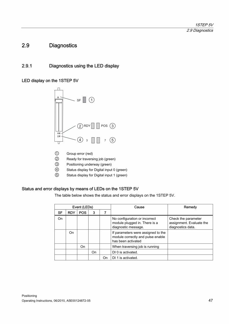
LED display on the 1STEP 5V
1
2 3
4 5 3 7 ① Group error (red) ② Ready for traversing job (green) ③ Positioning underway (green) ④ Status display for Digital input 0 (green) ⑤ Status display for Digital input 1 (green)
Status and error displays by means of LEDs on the 1STEP 5V The table below shows the status and error displays on the 1STEP 5V.
Event (LEDs) SF RDY POS 3 7
Cause Remedy
On No configuration or incorrect module plugged in. There is a diagnostic message.
Check the parameter assignment. Evaluate the diagnostics data.
On If parameters were assigned to the module correctly and pulse enable has been activated
On When traversing job is running On DI 0 is activated. On DI 1 is activated.
1STEP 5V 2.9 Diagnostics
Positioning 48 Operating Instructions, 06/2010, A5E00124872-05
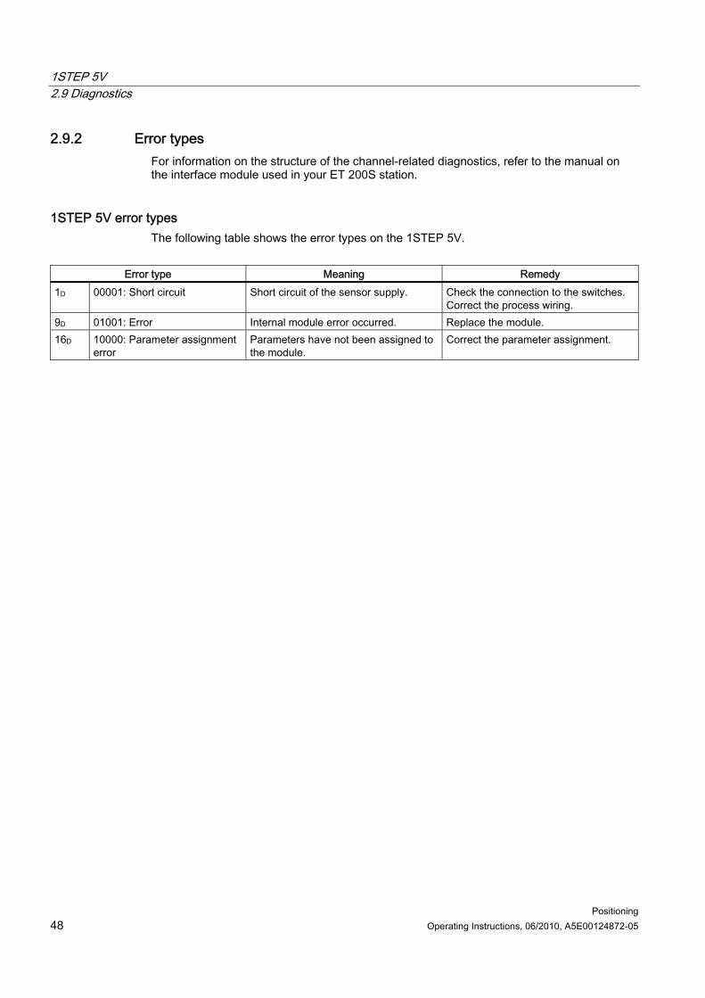
2.9.2 Error types For information on the structure of the channel-related diagnostics, refer to the manual on the interface module used in your ET 200S station.
1STEP 5V error types The following table shows the error types on the 1STEP 5V.
Error type Meaning Remedy
1D 00001: Short circuit Short circuit of the sensor supply. Check the connection to the switches. Correct the process wiring.
9D 01001: Error Internal module error occurred. Replace the module. 16D 10000: Parameter assignment
error Parameters have not been assigned to the module.
Correct the parameter assignment.
1STEP 5V 2.10 Feedback and Control Interface
Positioning Operating Instructions, 06/2010, A5E00124872-05 49
2.10 Feedback and Control Interface
2.10.1 Assignment of the Feedback and Control Interfaces
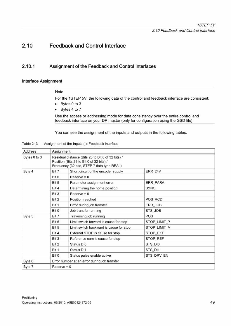
Interface Assignment
Note For the 1STEP 5V, the following data of the control and feedback interface are consistent: Bytes 0 to 3 Bytes 4 to 7 Use the access or addressing mode for data consistency over the entire control and feedback interface on your DP master (only for configuration using the GSD file).
You can see the assignment of the inputs and outputs in the following tables:
Table 2- 3 Assignment of the Inputs (I): Feedback interface
Address Assignment Bytes 0 to 3 Residual distance (Bits 23 to Bit 0 of 32 bits) /
Position (Bits 23 to Bit 0 of 32 bits) / Frequency (32 bits, STEP 7 data type REAL) Bit 7 Short circuit of the encoder supply ERR_24V Bit 6 Reserve = 0 Bit 5 Parameter assignment error ERR_PARA Bit 4 Determining the home position SYNC Bit 3 Reserve = 0 Bit 2 Position reached POS_RCD Bit 1 Error during job transfer ERR_JOB
Byte 4
Bit 0 Job transfer running STS_JOB Bit 7 Traversing job running POS Bit 6 Limit switch forward is cause for stop STOP_LIMIT_P Bit 5 Limit switch backward is cause for stop STOP_LIMIT_M Bit 4 External STOP is cause for stop STOP_EXT Bit 3 Reference cam is cause for stop STOP_REF Bit 2 Status DI0 STS_DI0 Bit 1 Status DI1 STS_DI1
Byte 5
Bit 0 Status pulse enable active STS_DRV_EN Byte 6 Error number at an error during job transfer Byte 7 Reserve = 0
1STEP 5V 2.10 Feedback and Control Interface
Positioning 50 Operating Instructions, 06/2010, A5E00124872-05
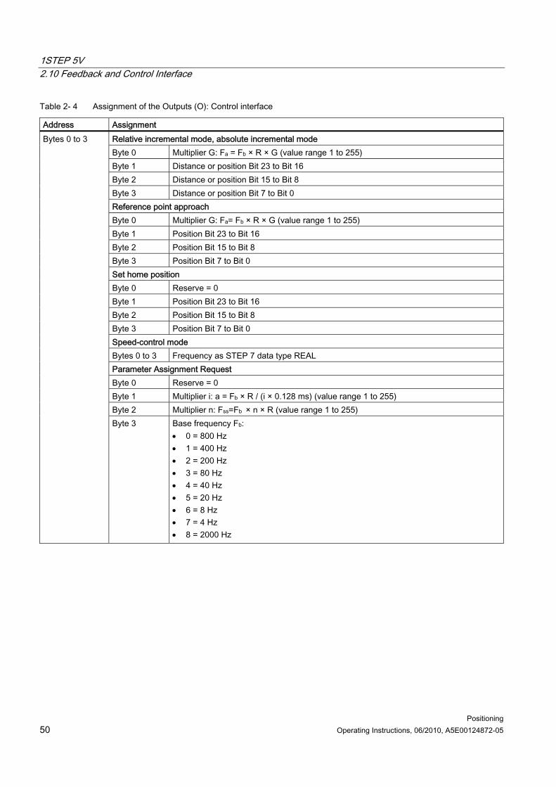
Table 2- 4 Assignment of the Outputs (O): Control interface
Address Assignment Relative incremental mode, absolute incremental mode Byte 0 Multiplier G: Fa = Fb × R × G (value range 1 to 255) Byte 1 Distance or position Bit 23 to Bit 16 Byte 2 Distance or position Bit 15 to Bit 8 Byte 3 Distance or position Bit 7 to Bit 0 Reference point approach Byte 0 Multiplier G: Fa= Fb × R × G (value range 1 to 255) Byte 1 Position Bit 23 to Bit 16 Byte 2 Position Bit 15 to Bit 8 Byte 3 Position Bit 7 to Bit 0 Set home position Byte 0 Reserve = 0 Byte 1 Position Bit 23 to Bit 16 Byte 2 Position Bit 15 to Bit 8 Byte 3 Position Bit 7 to Bit 0 Speed-control mode Bytes 0 to 3 Frequency as STEP 7 data type REAL Parameter Assignment Request Byte 0 Reserve = 0 Byte 1 Multiplier i: a = Fb × R / (i × 0.128 ms) (value range 1 to 255) Byte 2 Multiplier n: Fss=Fb × n × R (value range 1 to 255)
Bytes 0 to 3
Byte 3 Base frequency Fb: 0 = 800 Hz 1 = 400 Hz 2 = 200 Hz 3 = 80 Hz 4 = 40 Hz 5 = 20 Hz 6 = 8 Hz 7 = 4 Hz 8 = 2000 Hz
1STEP 5V 2.10 Feedback and Control Interface
Positioning Operating Instructions, 06/2010, A5E00124872-05 51
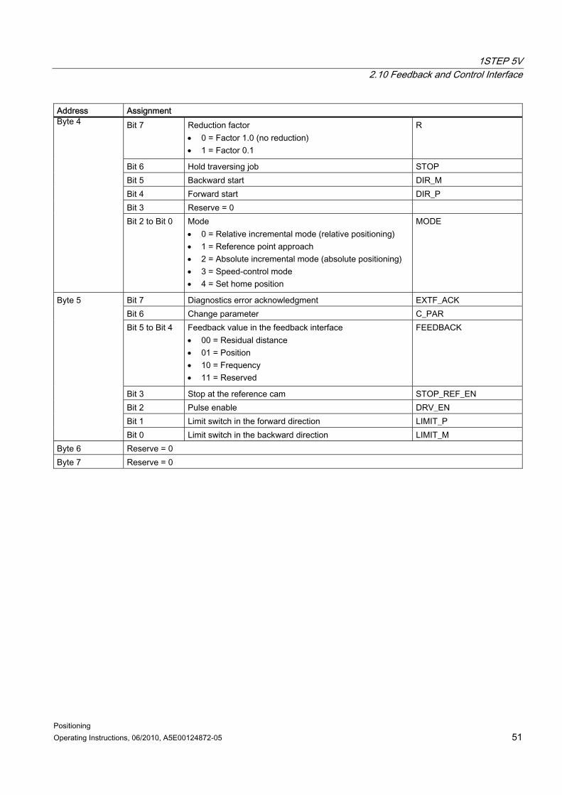
Address Assignment Bit 7 Reduction factor
0 = Factor 1.0 (no reduction) 1 = Factor 0.1
R
Bit 6 Hold traversing job STOP Bit 5 Backward start DIR_M Bit 4 Forward start DIR_P Bit 3 Reserve = 0
Byte 4
Bit 2 to Bit 0 Mode 0 = Relative incremental mode (relative positioning) 1 = Reference point approach 2 = Absolute incremental mode (absolute positioning) 3 = Speed-control mode 4 = Set home position
MODE
Bit 7 Diagnostics error acknowledgment EXTF_ACK Bit 6 Change parameter C_PAR Bit 5 to Bit 4 Feedback value in the feedback interface
00 = Residual distance 01 = Position 10 = Frequency 11 = Reserved
FEEDBACK
Bit 3 Stop at the reference cam STOP_REF_EN Bit 2 Pulse enable DRV_EN Bit 1 Limit switch in the forward direction LIMIT_P
Byte 5
Bit 0 Limit switch in the backward direction LIMIT_M Byte 6 Reserve = 0 Byte 7 Reserve = 0
1STEP 5V 2.10 Feedback and Control Interface
Positioning 52 Operating Instructions, 06/2010, A5E00124872-05
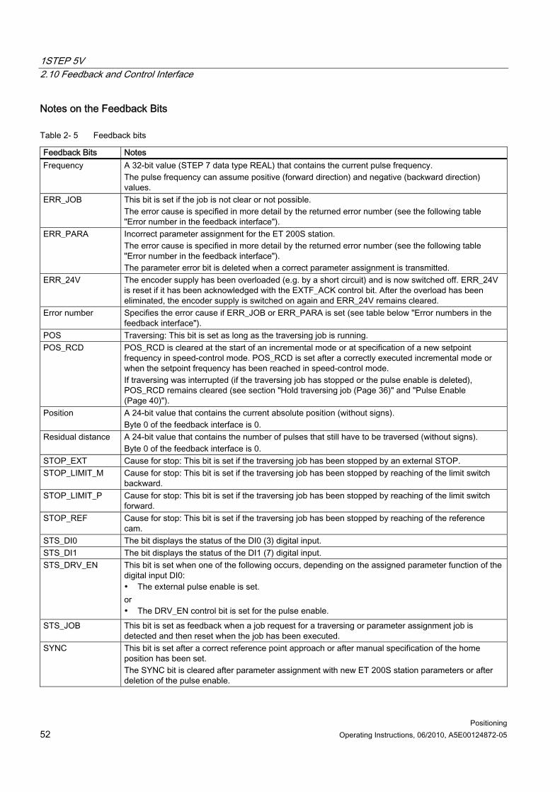
Notes on the Feedback Bits
Table 2- 5 Feedback bits
Feedback Bits Notes Frequency A 32-bit value (STEP 7 data type REAL) that contains the current pulse frequency.
The pulse frequency can assume positive (forward direction) and negative (backward direction) values.
ERR_JOB This bit is set if the job is not clear or not possible. The error cause is specified in more detail by the returned error number (see the following table "Error number in the feedback interface").
ERR_PARA Incorrect parameter assignment for the ET 200S station. The error cause is specified in more detail by the returned error number (see the following table "Error number in the feedback interface"). The parameter error bit is deleted when a correct parameter assignment is transmitted.
ERR_24V The encoder supply has been overloaded (e.g. by a short circuit) and is now switched off. ERR_24V is reset if it has been acknowledged with the EXTF_ACK control bit. After the overload has been eliminated, the encoder supply is switched on again and ERR_24V remains cleared.
Error number Specifies the error cause if ERR_JOB or ERR_PARA is set (see table below "Error numbers in the feedback interface").
POS Traversing: This bit is set as long as the traversing job is running. POS_RCD POS_RCD is cleared at the start of an incremental mode or at specification of a new setpoint
frequency in speed-control mode. POS_RCD is set after a correctly executed incremental mode or when the setpoint frequency has been reached in speed-control mode. If traversing was interrupted (if the traversing job has stopped or the pulse enable is deleted), POS_RCD remains cleared (see section "Hold traversing job (Page 36)" and "Pulse Enable (Page 40)").
Position A 24-bit value that contains the current absolute position (without signs). Byte 0 of the feedback interface is 0.
Residual distance A 24-bit value that contains the number of pulses that still have to be traversed (without signs). Byte 0 of the feedback interface is 0.
STOP_EXT Cause for stop: This bit is set if the traversing job has been stopped by an external STOP. STOP_LIMIT_M Cause for stop: This bit is set if the traversing job has been stopped by reaching of the limit switch
backward. STOP_LIMIT_P Cause for stop: This bit is set if the traversing job has been stopped by reaching of the limit switch
forward. STOP_REF Cause for stop: This bit is set if the traversing job has been stopped by reaching of the reference
cam. STS_DI0 The bit displays the status of the DI0 (3) digital input. STS_DI1 The bit displays the status of the DI1 (7) digital input. STS_DRV_EN This bit is set when one of the following occurs, depending on the assigned parameter function of the
digital input DI0: The external pulse enable is set. or The DRV_EN control bit is set for the pulse enable.
STS_JOB This bit is set as feedback when a job request for a traversing or parameter assignment job is detected and then reset when the job has been executed.
SYNC This bit is set after a correct reference point approach or after manual specification of the home position has been set. The SYNC bit is cleared after parameter assignment with new ET 200S station parameters or after deletion of the pulse enable.
1STEP 5V 2.10 Feedback and Control Interface
Positioning Operating Instructions, 06/2010, A5E00124872-05 53
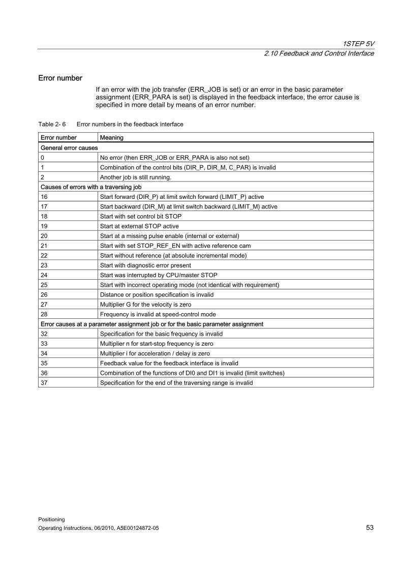
Error number If an error with the job transfer (ERR_JOB is set) or an error in the basic parameter assignment (ERR_PARA is set) is displayed in the feedback interface, the error cause is specified in more detail by means of an error number.
Table 2- 6 Error numbers in the feedback interface
Error number Meaning General error causes 0 No error (then ERR_JOB or ERR_PARA is also not set) 1 Combination of the control bits (DIR_P, DIR_M, C_PAR) is invalid 2 Another job is still running. Causes of errors with a traversing job 16 Start forward (DIR_P) at limit switch forward (LIMIT_P) active 17 Start backward (DIR_M) at limit switch backward (LIMIT_M) active 18 Start with set control bit STOP 19 Start at external STOP active 20 Start at a missing pulse enable (internal or external) 21 Start with set STOP_REF_EN with active reference cam 22 Start without reference (at absolute incremental mode) 23 Start with diagnostic error present 24 Start was interrupted by CPU/master STOP 25 Start with incorrect operating mode (not identical with requirement) 26 Distance or position specification is invalid 27 Multiplier G for the velocity is zero 28 Frequency is invalid at speed-control mode Error causes at a parameter assignment job or for the basic parameter assignment 32 Specification for the basic frequency is invalid 33 Multiplier n for start-stop frequency is zero 34 Multiplier i for acceleration / delay is zero 35 Feedback value for the feedback interface is invalid 36 Combination of the functions of DI0 and DI1 is invalid (limit switches) 37 Specification for the end of the traversing range is invalid
1STEP 5V 2.10 Feedback and Control Interface
Positioning 54 Operating Instructions, 06/2010, A5E00124872-05
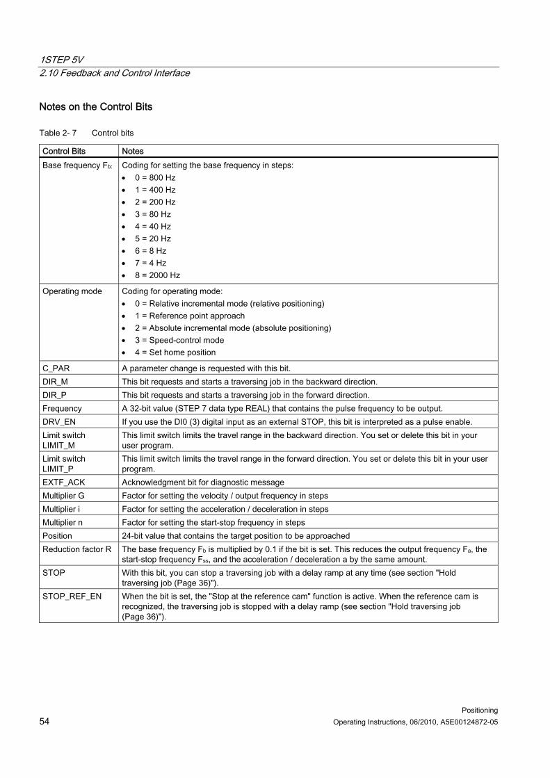
Notes on the Control Bits
Table 2- 7 Control bits
Control Bits Notes Base frequency Fb: Coding for setting the base frequency in steps:
0 = 800 Hz 1 = 400 Hz 2 = 200 Hz 3 = 80 Hz 4 = 40 Hz 5 = 20 Hz 6 = 8 Hz 7 = 4 Hz 8 = 2000 Hz
Operating mode Coding for operating mode: 0 = Relative incremental mode (relative positioning) 1 = Reference point approach 2 = Absolute incremental mode (absolute positioning) 3 = Speed-control mode 4 = Set home position
C_PAR A parameter change is requested with this bit. DIR_M This bit requests and starts a traversing job in the backward direction. DIR_P This bit requests and starts a traversing job in the forward direction. Frequency A 32-bit value (STEP 7 data type REAL) that contains the pulse frequency to be output. DRV_EN If you use the DI0 (3) digital input as an external STOP, this bit is interpreted as a pulse enable. Limit switch LIMIT_M
This limit switch limits the travel range in the backward direction. You set or delete this bit in your user program.
Limit switch LIMIT_P
This limit switch limits the travel range in the forward direction. You set or delete this bit in your user program.
EXTF_ACK Acknowledgment bit for diagnostic message Multiplier G Factor for setting the velocity / output frequency in steps Multiplier i Factor for setting the acceleration / deceleration in steps Multiplier n Factor for setting the start-stop frequency in steps Position 24-bit value that contains the target position to be approached Reduction factor R The base frequency Fb is multiplied by 0.1 if the bit is set. This reduces the output frequency Fa, the
start-stop frequency Fss, and the acceleration / deceleration a by the same amount. STOP With this bit, you can stop a traversing job with a delay ramp at any time (see section "Hold
traversing job (Page 36)"). STOP_REF_EN When the bit is set, the "Stop at the reference cam" function is active. When the reference cam is
recognized, the traversing job is stopped with a delay ramp (see section "Hold traversing job (Page 36)").
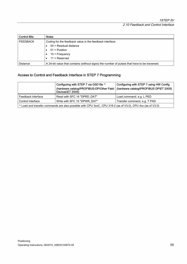
1STEP 5V 2.10 Feedback and Control Interface
Positioning Operating Instructions, 06/2010, A5E00124872-05 55
Control Bits Notes FEEDBACK Coding for the feedback value in the feedback interface:
00 = Residual distance 01 = Position 10 = Frequency 11 = Reserved
Distance A 24-bit value that contains (without signs) the number of pulses that have to be traversed.
Access to Control and Feedback Interface in STEP 7 Programming Configuring with STEP 7 via GSD file 1)
(hardware catalog\PROFIBUS-DP\Other Field Devices\ET 200S)
Configuring with STEP 7 using HW Config (hardware catalog\PROFIBUS DP\ET 200S)
Feedback interface Read with SFC 14 "DPRD_DAT" Load command, e.g. L PED Control interface Write with SFC 15 "DPWR_DAT" Transfer command, e.g. T PAD 1) Load and transfer commands are also possible with CPU 3xxC, CPU 318-2 (as of V3.0), CPU 4xx (as of V3.0)
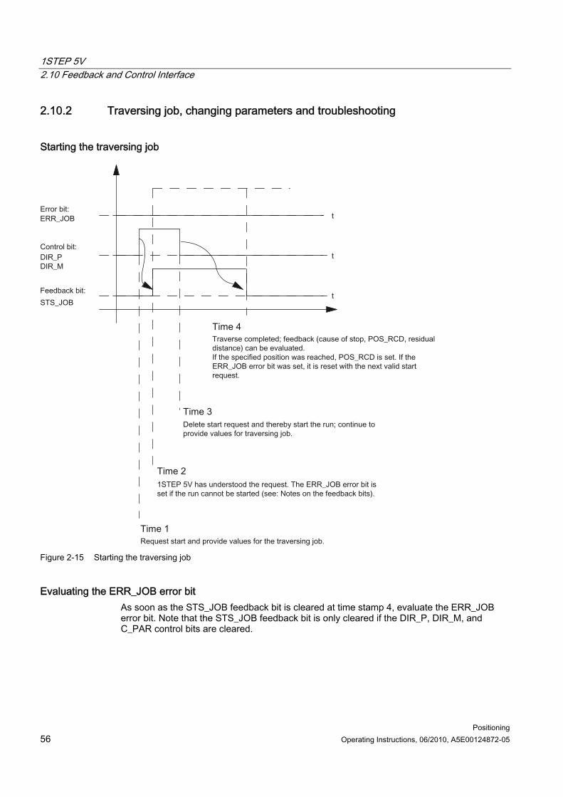
1STEP 5V 2.10 Feedback and Control Interface
Positioning 56 Operating Instructions, 06/2010, A5E00124872-05
2.10.2 Traversing job, changing parameters and troubleshooting
Starting the traversing job
Figure 2-15 Starting the traversing job
Evaluating the ERR_JOB error bit As soon as the STS_JOB feedback bit is cleared at time stamp 4, evaluate the ERR_JOB error bit. Note that the STS_JOB feedback bit is only cleared if the DIR_P, DIR_M, and C_PAR control bits are cleared.
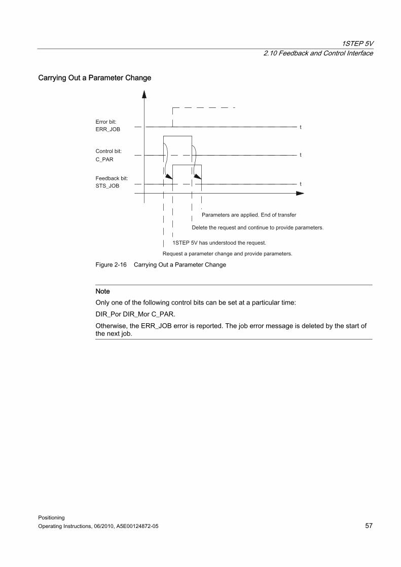
1STEP 5V 2.10 Feedback and Control Interface
Positioning Operating Instructions, 06/2010, A5E00124872-05 57
Carrying Out a Parameter Change
Figure 2-16 Carrying Out a Parameter Change
Note Only one of the following control bits can be set at a particular time: DIR_Por DIR_Mor C_PAR. Otherwise, the ERR_JOB error is reported. The job error message is deleted by the start of the next job.
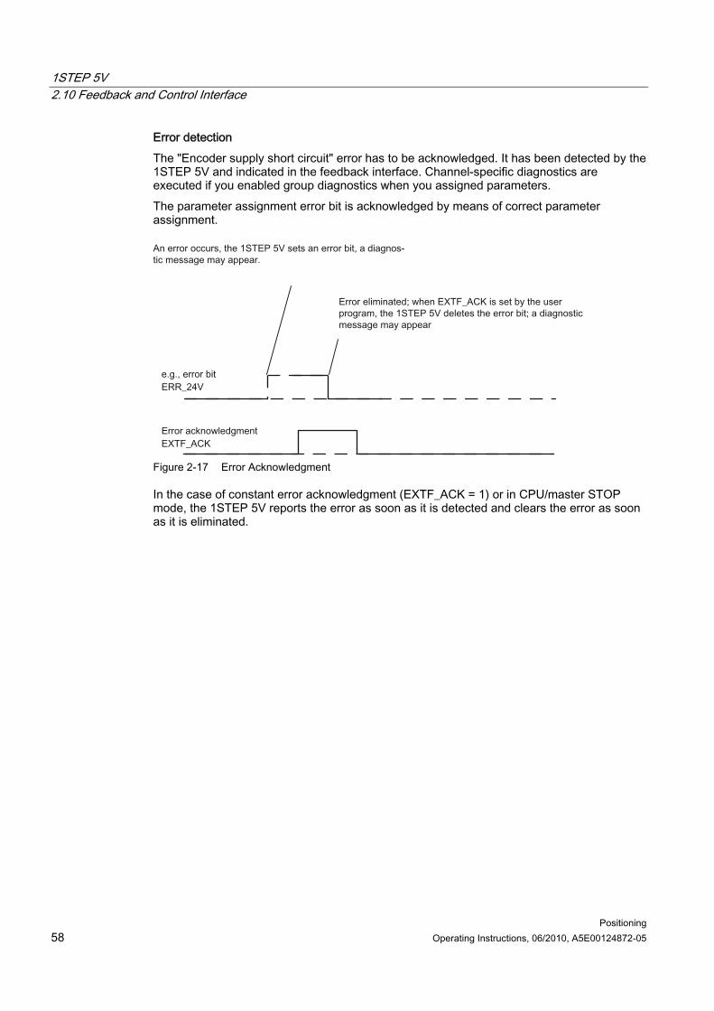
1STEP 5V 2.10 Feedback and Control Interface
Positioning 58 Operating Instructions, 06/2010, A5E00124872-05
Error detection The "Encoder supply short circuit" error has to be acknowledged. It has been detected by the 1STEP 5V and indicated in the feedback interface. Channel-specific diagnostics are executed if you enabled group diagnostics when you assigned parameters. The parameter assignment error bit is acknowledged by means of correct parameter assignment.
Figure 2-17 Error Acknowledgment
In the case of constant error acknowledgment (EXTF_ACK = 1) or in CPU/master STOP mode, the 1STEP 5V reports the error as soon as it is detected and clears the error as soon as it is eliminated.
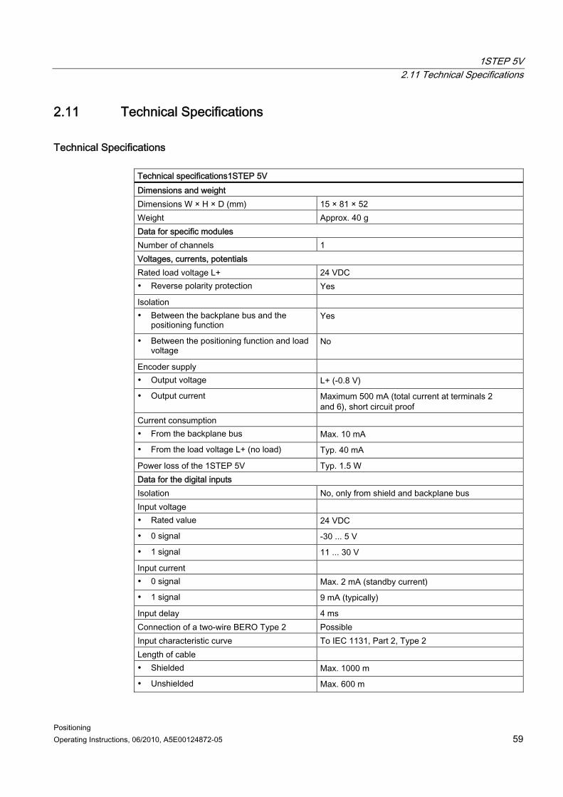
1STEP 5V 2.11 Technical Specifications
Positioning Operating Instructions, 06/2010, A5E00124872-05 59
2.11 Technical Specifications
Technical Specifications Technical specifications1STEP 5V Dimensions and weight Dimensions W × H × D (mm) 15 × 81 × 52 Weight Approx. 40 g Data for specific modules Number of channels 1 Voltages, currents, potentials Rated load voltage L+ 24 VDC Reverse polarity protection Yes
Isolation Between the backplane bus and the
positioning function Yes
Between the positioning function and load voltage
No
Encoder supply Output voltage L+ (-0.8 V)
Output current Maximum 500 mA (total current at terminals 2 and 6), short circuit proof
Current consumption From the backplane bus Max. 10 mA
From the load voltage L+ (no load) Typ. 40 mA
Power loss of the 1STEP 5V Typ. 1.5 W Data for the digital inputs Isolation No, only from shield and backplane bus Input voltage Rated value 24 VDC
0 signal -30 ... 5 V
1 signal 11 ... 30 V
Input current 0 signal Max. 2 mA (standby current)
1 signal 9 mA (typically)
Input delay 4 ms Connection of a two-wire BERO Type 2 Possible Input characteristic curve To IEC 1131, Part 2, Type 2 Length of cable Shielded Max. 1000 m
Unshielded Max. 600 m
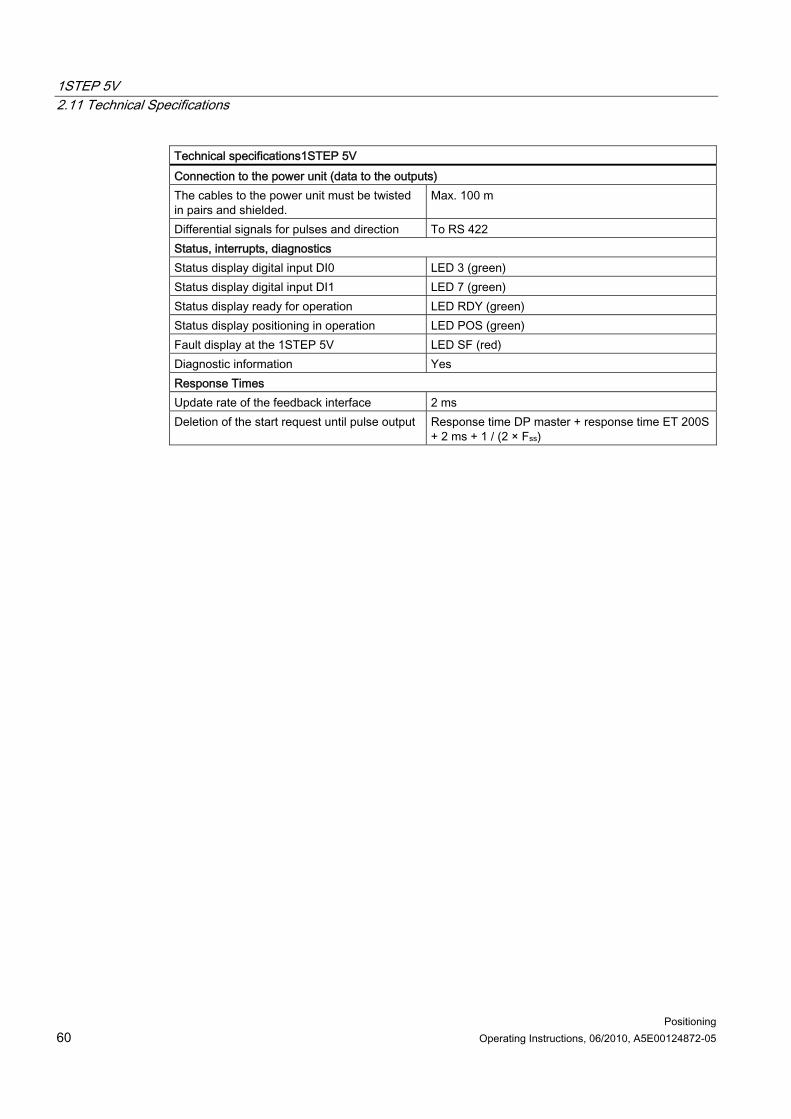
1STEP 5V 2.11 Technical Specifications
Positioning 60 Operating Instructions, 06/2010, A5E00124872-05
Technical specifications1STEP 5V Connection to the power unit (data to the outputs) The cables to the power unit must be twisted in pairs and shielded.
Max. 100 m
Differential signals for pulses and direction To RS 422 Status, interrupts, diagnostics Status display digital input DI0 LED 3 (green) Status display digital input DI1 LED 7 (green) Status display ready for operation LED RDY (green) Status display positioning in operation LED POS (green) Fault display at the 1STEP 5V LED SF (red) Diagnostic information Yes Response Times Update rate of the feedback interface 2 ms Deletion of the start request until pulse output Response time DP master + response time ET 200S
+ 2 ms + 1 / (2 × Fss)
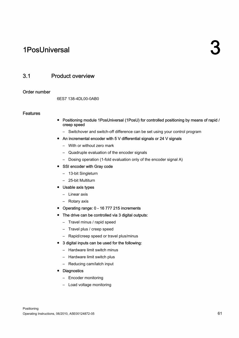
Positioning Operating Instructions, 06/2010, A5E00124872-05 61
1PosUniversal 33.1 Product overview
Order number 6ES7 138-4DL00-0AB0
Features Positioning module 1PosUniversal (1PosU) for controlled positioning by means of rapid /
creep speed – Switchover and switch-off difference can be set using your control program
An incremental encoder with 5 V differential signals or 24 V signals – With or without zero mark – Quadruple evaluation of the encoder signals – Dosing operation (1-fold evaluation only of the encoder signal A)
SSI encoder with Gray code – 13-bit Singleturn – 25-bit Multiturn
Usable axis types – Linear axis – Rotary axis
Operating range: 0 - 16 777 215 increments The drive can be controlled via 3 digital outputs:
– Travel minus / rapid speed – Travel plus / creep speed – Rapid/creep speed or travel plus/minus
3 digital inputs can be used for the following: – Hardware limit switch minus – Hardware limit switch plus – Reducing cam/latch input
Diagnostics – Encoder monitoring – Load voltage monitoring
1PosUniversal 3.1 Product overview
Positioning 62 Operating Instructions, 06/2010, A5E00124872-05
Firmware update1) – In order to extend the functionality and eliminate errors, firmware updates can be
downloaded to the operating system memory of the 1PosU by means of the STEP 7 HW Config software.
Note When you start the firmware update, the old firmware is deleted. If the firmware update is interrupted or canceled for any reason, 1PosU will no longer function correctly as a result. Restart the firmware update and wait until it has completed successfully.
Information function 1) – Hardware version – Firmware product version – Serial number
1) The function is only available if the used interface module supports the required system services
Configuration In order to configure the 1PosU use one of the following A GSD file (http://www.automation.siemens.com/csi/gsd) STEP 7 as of Version V5.3 SP2 or with the HSP (hardware support package, available
online) as of STEP 7 Version V.5.2 SP1
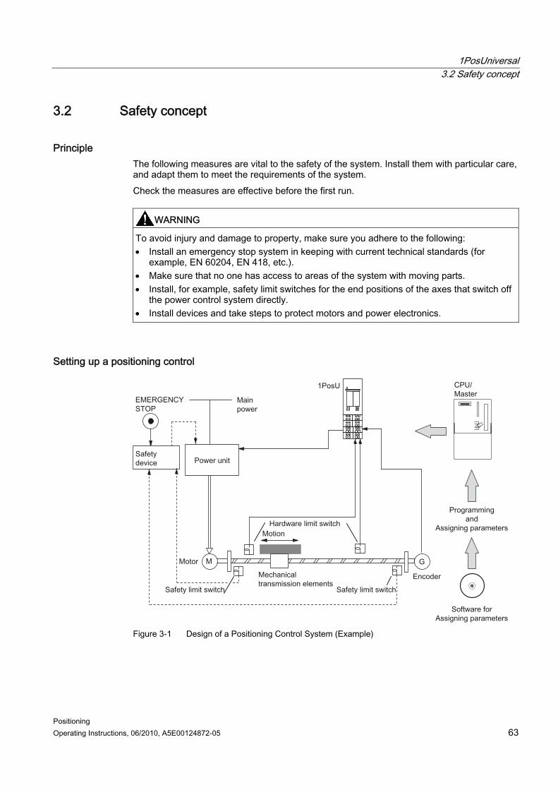
1PosUniversal 3.2 Safety concept
Positioning Operating Instructions, 06/2010, A5E00124872-05 63
3.2 Safety concept
Principle The following measures are vital to the safety of the system. Install them with particular care, and adapt them to meet the requirements of the system. Check the measures are effective before the first run.
WARNING To avoid injury and damage to property, make sure you adhere to the following: Install an emergency stop system in keeping with current technical standards (for
example, EN 60204, EN 418, etc.). Make sure that no one has access to areas of the system with moving parts. Install, for example, safety limit switches for the end positions of the axes that switch off
the power control system directly. Install devices and take steps to protect motors and power electronics.
Setting up a positioning control
Figure 3-1 Design of a Positioning Control System (Example)
1PosUniversal 3.3 Brief Instructions on Commissioning the 1PosU
Positioning 64 Operating Instructions, 06/2010, A5E00124872-05
3.3 Brief Instructions on Commissioning the 1PosU
Introduction These brief instructions guide you to a functioning application that will enable you to become familiar and check the basic hardware and software involved in a positioning operation of your 1PosU. The inching mode used in this example.
Prerequisites for the Example The following prerequisites must be fulfilled: You must have put an ET 200S station on an S7 station with a DP master into operation. You must have:
– A terminal module TM-E30x44-01 (order number 6ES7 193-4CGx0-0AA0)
– A 1PosU (order number 6ES7 138-4DL00-0AB0)
– A position encoder (incremental encoder with 5 V differential signals, incremental encoder with 24 V signals or SSI encoder)
– A drive with power control (e.g. a pole-changing motor with contactor switching) – A 24 VDC power supply – The necessary wiring material
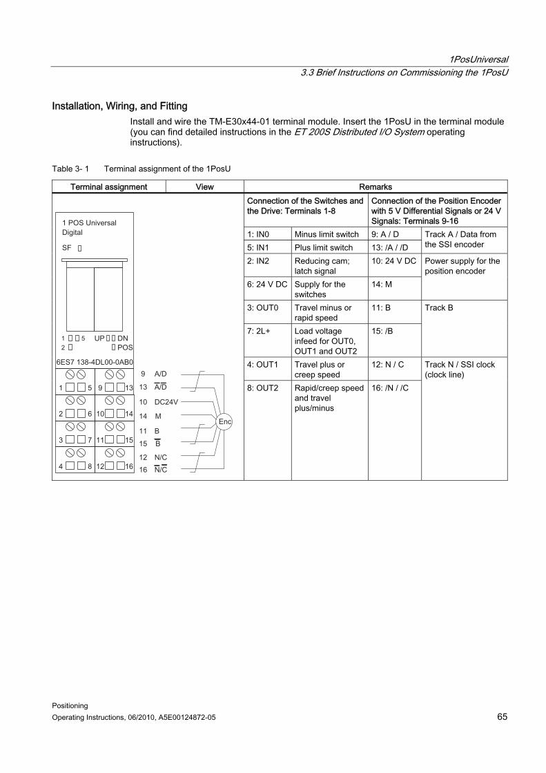
1PosUniversal 3.3 Brief Instructions on Commissioning the 1PosU
Positioning Operating Instructions, 06/2010, A5E00124872-05 65
Installation, Wiring, and Fitting Install and wire the TM-E30x44-01 terminal module. Insert the 1PosU in the terminal module (you can find detailed instructions in the ET 200S Distributed I/O System operating instructions).
Table 3- 1 Terminal assignment of the 1PosU
Terminal assignment View Remarks Connection of the Switches and the Drive: Terminals 1-8
Connection of the Position Encoder with 5 V Differential Signals or 24 V Signals: Terminals 9-16
1: IN0 Minus limit switch 9: A / D 5: IN1 Plus limit switch 13: /A / /D
Track A / Data from the SSI encoder
2: IN2 Reducing cam; latch signal
10: 24 V DC
6: 24 V DC Supply for the switches
14: M
Power supply for the position encoder
3: OUT0 Travel minus or rapid speed
11: B
7: 2L+ Load voltage infeed for OUT0, OUT1 and OUT2
15: /B
Track B
4: OUT1 Travel plus or creep speed
12: N / C
8: OUT2 Rapid/creep speed and travel plus/minus
16: /N / /C
Track N / SSI clock (clock line)
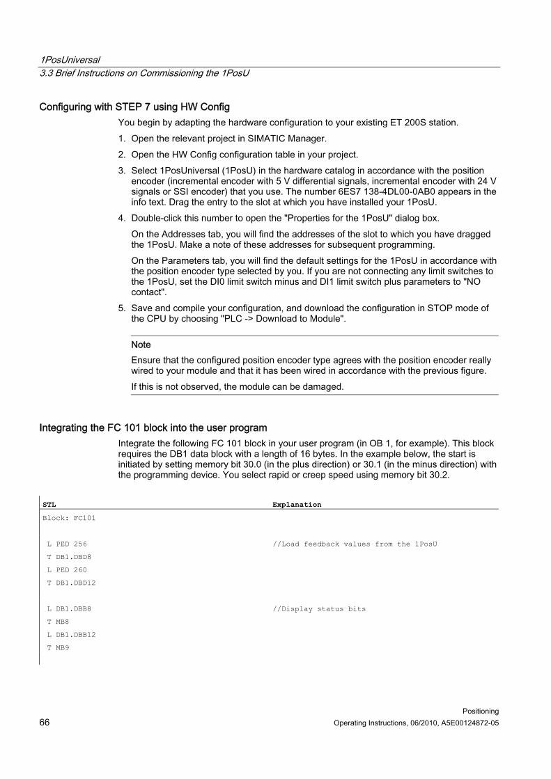
1PosUniversal 3.3 Brief Instructions on Commissioning the 1PosU
Positioning 66 Operating Instructions, 06/2010, A5E00124872-05
Configuring with STEP 7 using HW Config You begin by adapting the hardware configuration to your existing ET 200S station. 1. Open the relevant project in SIMATIC Manager. 2. Open the HW Config configuration table in your project. 3. Select 1PosUniversal (1PosU) in the hardware catalog in accordance with the position
encoder (incremental encoder with 5 V differential signals, incremental encoder with 24 V signals or SSI encoder) that you use. The number 6ES7 138-4DL00-0AB0 appears in the info text. Drag the entry to the slot at which you have installed your 1PosU.
4. Double-click this number to open the "Properties for the 1PosU" dialog box. On the Addresses tab, you will find the addresses of the slot to which you have dragged the 1PosU. Make a note of these addresses for subsequent programming. On the Parameters tab, you will find the default settings for the 1PosU in accordance with the position encoder type selected by you. If you are not connecting any limit switches to the 1PosU, set the DI0 limit switch minus and DI1 limit switch plus parameters to "NO contact".
5. Save and compile your configuration, and download the configuration in STOP mode of the CPU by choosing "PLC -> Download to Module".
Note Ensure that the configured position encoder type agrees with the position encoder really wired to your module and that it has been wired in accordance with the previous figure. If this is not observed, the module can be damaged.
Integrating the FC 101 block into the user program Integrate the following FC 101 block in your user program (in OB 1, for example). This block requires the DB1 data block with a length of 16 bytes. In the example below, the start is initiated by setting memory bit 30.0 (in the plus direction) or 30.1 (in the minus direction) with the programming device. You select rapid or creep speed using memory bit 30.2.
STL Explanation
Block: FC101
L PED 256
T DB1.DBD8
L PED 260
T DB1.DBD12
//Load feedback values from the 1PosU
L DB1.DBB8
T MB8
L DB1.DBB12
T MB9
//Display status bits
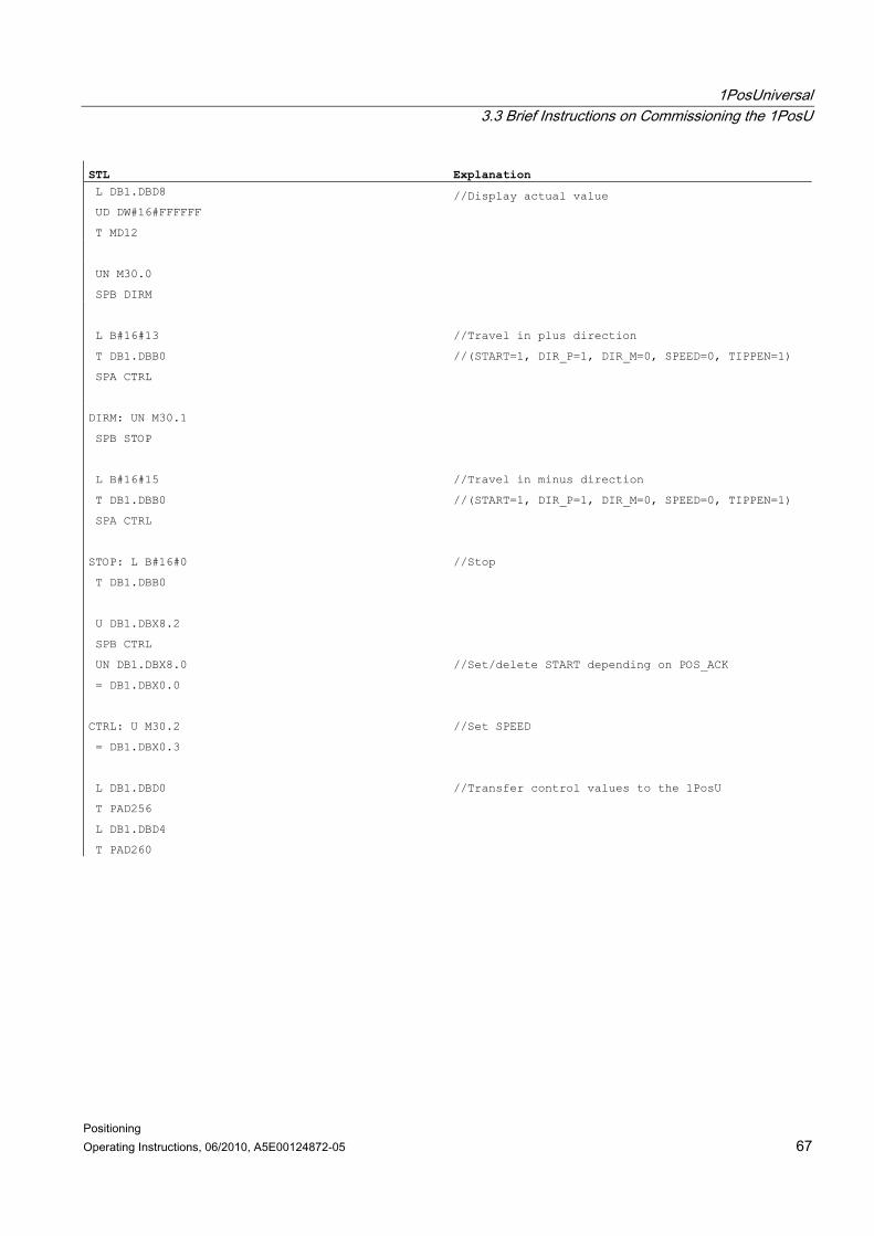
1PosUniversal 3.3 Brief Instructions on Commissioning the 1PosU
Positioning Operating Instructions, 06/2010, A5E00124872-05 67
STL Explanation
L DB1.DBD8
UD DW#16#FFFFFF
T MD12
//Display actual value
UN M30.0
SPB DIRM
L B#16#13
T DB1.DBB0
SPA CTRL
//Travel in plus direction
//(START=1, DIR_P=1, DIR_M=0, SPEED=0, TIPPEN=1)
DIRM: UN M30.1
SPB STOP
L B#16#15
T DB1.DBB0
SPA CTRL
//Travel in minus direction
//(START=1, DIR_P=1, DIR_M=0, SPEED=0, TIPPEN=1)
STOP: L B#16#0
T DB1.DBB0
U DB1.DBX8.2
SPB CTRL
UN DB1.DBX8.0
= DB1.DBX0.0
//Stop
//Set/delete START depending on POS_ACK
CTRL: U M30.2
= DB1.DBX0.3
L DB1.DBD0
T PAD256
L DB1.DBD4
T PAD260
//Set SPEED
//Transfer control values to the 1PosU
1PosUniversal 3.3 Brief Instructions on Commissioning the 1PosU
Positioning 68 Operating Instructions, 06/2010, A5E00124872-05
Test Start inching mode, and monitor the associated feedback. 1. Using "Monitor/Modify Variables", check the actual value and the status bits POS_ACK,
POS_ERR, POS_DONE, ERR_ENCODER and ERR_2L+. 2. Select the "Block" folder in your project. Choose the "Insert > S7 Block > Variable Table"
menu command to insert the VAT 1 variable table, and then confirm with OK. 3. Open the VAT 1 variable table, and enter the following variables in the "Address" column:
– MD12 (actual value) – M8.0 (POS_ACK) – M8.1 (POS_ERR) – M8.2 (POS_DONE) – M8.7 (ERR_ENCODER) – M9.7 (ERR_2L+) – M30.0 (inching in plus direction) – M30.1 (inching in minus direction) – M30.2 (SPEED; 0 = creep speed; 1 = rapid speed)
4. Choose "PLC > File Connect To > Configured CPU" to switch to online. 5. Choose "Variable > Monitor" to switch to monitoring. 6. Switch the CPU to RUN mode.
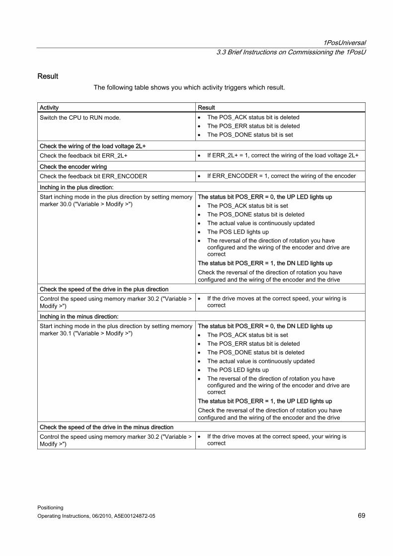
1PosUniversal 3.3 Brief Instructions on Commissioning the 1PosU
Positioning Operating Instructions, 06/2010, A5E00124872-05 69
Result The following table shows you which activity triggers which result.
Activity Result Switch the CPU to RUN mode. The POS_ACK status bit is deleted
The POS_ERR status bit is deleted The POS_DONE status bit is set
Check the wiring of the load voltage 2L+ Check the feedback bit ERR_2L+ If ERR_2L+ = 1, correct the wiring of the load voltage 2L+
Check the encoder wiring Check the feedback bit ERR_ENCODER If ERR_ENCODER = 1, correct the wiring of the encoder
Inching in the plus direction: Start inching mode in the plus direction by setting memory marker 30.0 ("Variable > Modify >")
The status bit POS_ERR = 0, the UP LED lights up The POS_ACK status bit is set The POS_DONE status bit is deleted The actual value is continuously updated The POS LED lights up The reversal of the direction of rotation you have
configured and the wiring of the encoder and drive are correct
The status bit POS_ERR = 1, the DN LED lights up Check the reversal of the direction of rotation you have configured and the wiring of the encoder and the drive
Check the speed of the drive in the plus direction Control the speed using memory marker 30.2 ("Variable > Modify >")
If the drive moves at the correct speed, your wiring is correct
Inching in the minus direction: Start inching mode in the plus direction by setting memory marker 30.1 ("Variable > Modify >")
The status bit POS_ERR = 0, the DN LED lights up The POS_ACK status bit is set The POS_ERR status bit is deleted The POS_DONE status bit is deleted The actual value is continuously updated The POS LED lights up The reversal of the direction of rotation you have
configured and the wiring of the encoder and drive are correct
The status bit POS_ERR = 1, the UP LED lights up Check the reversal of the direction of rotation you have configured and the wiring of the encoder and the drive
Check the speed of the drive in the minus direction Control the speed using memory marker 30.2 ("Variable > Modify >")
If the drive moves at the correct speed, your wiring is correct
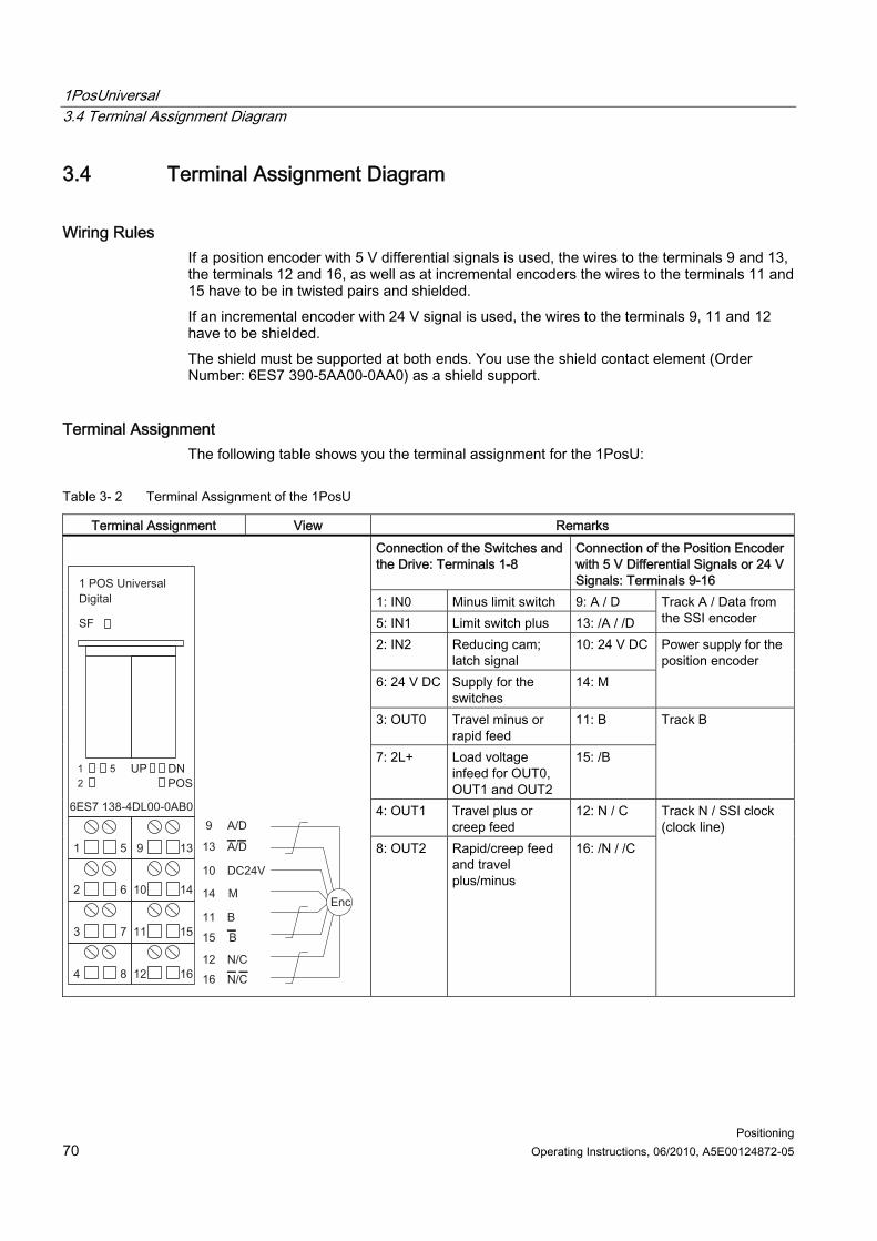
1PosUniversal 3.4 Terminal Assignment Diagram
Positioning 70 Operating Instructions, 06/2010, A5E00124872-05
3.4 Terminal Assignment Diagram
Wiring Rules If a position encoder with 5 V differential signals is used, the wires to the terminals 9 and 13, the terminals 12 and 16, as well as at incremental encoders the wires to the terminals 11 and 15 have to be in twisted pairs and shielded. If an incremental encoder with 24 V signal is used, the wires to the terminals 9, 11 and 12 have to be shielded. The shield must be supported at both ends. You use the shield contact element (Order Number: 6ES7 390-5AA00-0AA0) as a shield support.
Terminal Assignment The following table shows you the terminal assignment for the 1PosU:
Table 3- 2 Terminal Assignment of the 1PosU
Terminal Assignment View Remarks Connection of the Switches and the Drive: Terminals 1-8
Connection of the Position Encoder with 5 V Differential Signals or 24 V Signals: Terminals 9-16
1: IN0 Minus limit switch 9: A / D 5: IN1 Limit switch plus 13: /A / /D
Track A / Data from the SSI encoder
2: IN2 Reducing cam; latch signal
10: 24 V DC
6: 24 V DC Supply for the switches
14: M
Power supply for the position encoder
3: OUT0 Travel minus or rapid feed
11: B
7: 2L+ Load voltage infeed for OUT0, OUT1 and OUT2
15: /B
Track B
4: OUT1 Travel plus or creep feed
12: N / C
8: OUT2 Rapid/creep feed and travel plus/minus
16: /N / /C
Track N / SSI clock (clock line)
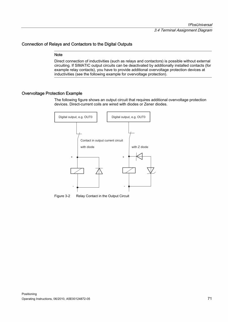
1PosUniversal 3.4 Terminal Assignment Diagram
Positioning Operating Instructions, 06/2010, A5E00124872-05 71
Connection of Relays and Contactors to the Digital Outputs
Note Direct connection of inductivities (such as relays and contactors) is possible without external circuiting. If SIMATIC output circuits can be deactivated by additionally installed contacts (for example relay contacts), you have to provide additional overvoltage protection devices at inductivities (see the following example for overvoltage protection).
Overvoltage Protection Example The following figure shows an output circuit that requires additional overvoltage protection devices. Direct-current coils are wired with diodes or Zener diodes.
Figure 3-2 Relay Contact in the Output Circuit
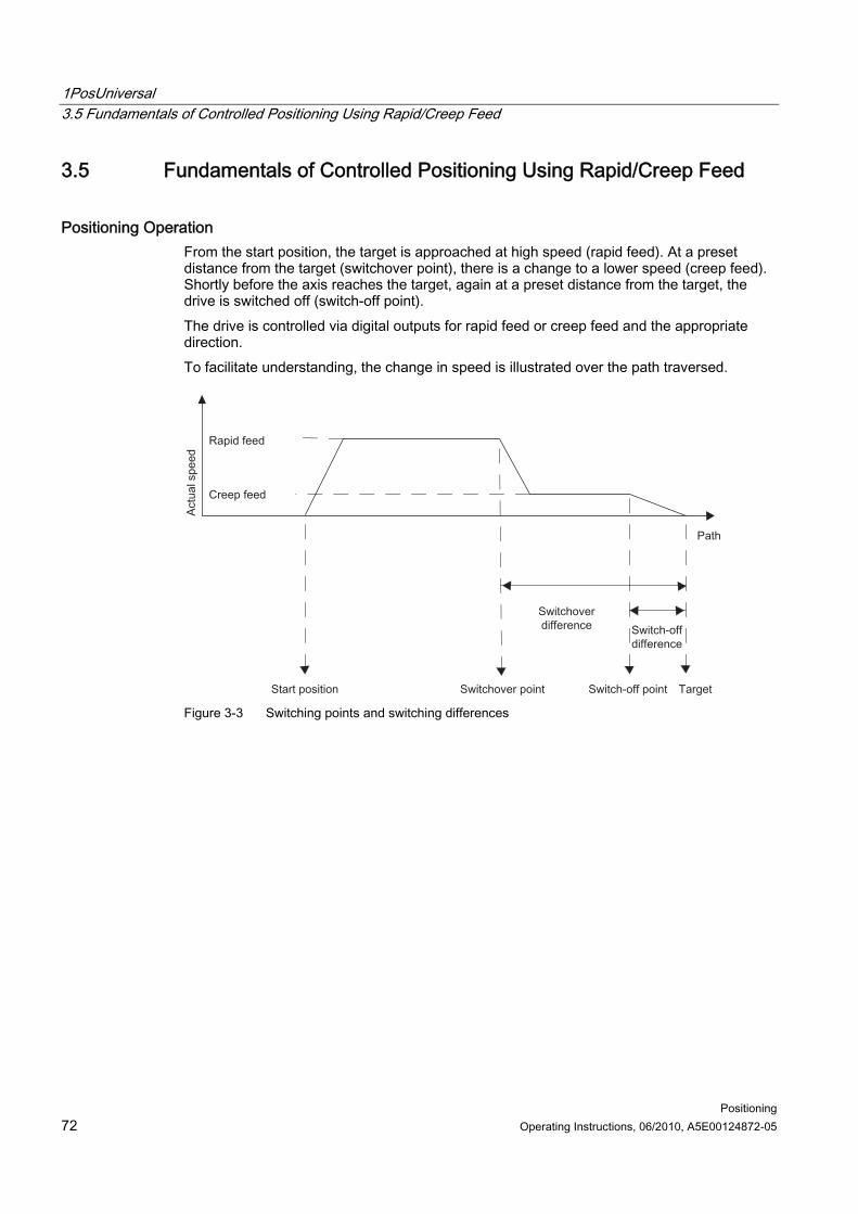
1PosUniversal 3.5 Fundamentals of Controlled Positioning Using Rapid/Creep Feed
Positioning 72 Operating Instructions, 06/2010, A5E00124872-05
3.5 Fundamentals of Controlled Positioning Using Rapid/Creep Feed
Positioning Operation From the start position, the target is approached at high speed (rapid feed). At a preset distance from the target (switchover point), there is a change to a lower speed (creep feed). Shortly before the axis reaches the target, again at a preset distance from the target, the drive is switched off (switch-off point). The drive is controlled via digital outputs for rapid feed or creep feed and the appropriate direction. To facilitate understanding, the change in speed is illustrated over the path traversed.
Figure 3-3 Switching points and switching differences
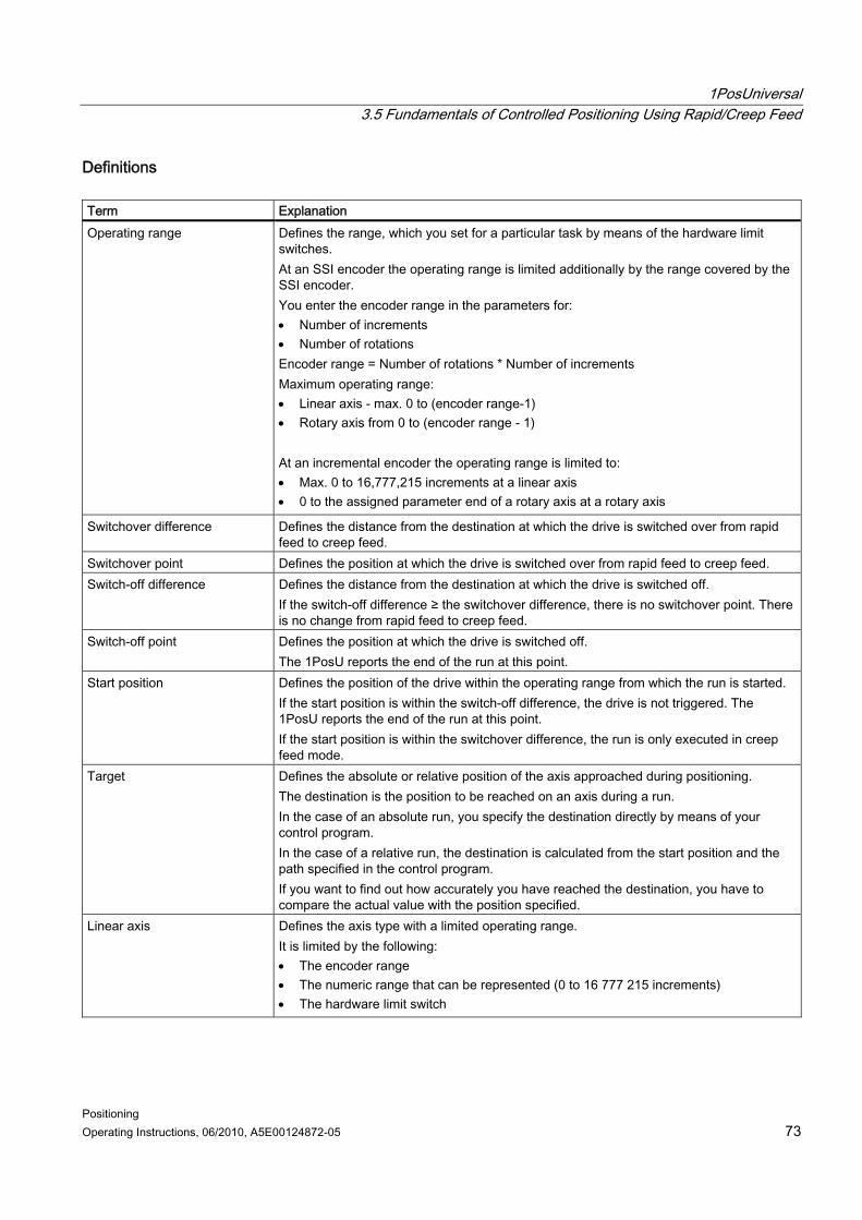
1PosUniversal 3.5 Fundamentals of Controlled Positioning Using Rapid/Creep Feed
Positioning Operating Instructions, 06/2010, A5E00124872-05 73
Definitions Term Explanation Operating range Defines the range, which you set for a particular task by means of the hardware limit
switches. At an SSI encoder the operating range is limited additionally by the range covered by the SSI encoder. You enter the encoder range in the parameters for: Number of increments Number of rotations Encoder range = Number of rotations * Number of increments Maximum operating range: Linear axis - max. 0 to (encoder range-1) Rotary axis from 0 to (encoder range - 1) At an incremental encoder the operating range is limited to: Max. 0 to 16,777,215 increments at a linear axis 0 to the assigned parameter end of a rotary axis at a rotary axis
Switchover difference Defines the distance from the destination at which the drive is switched over from rapid feed to creep feed.
Switchover point Defines the position at which the drive is switched over from rapid feed to creep feed. Switch-off difference Defines the distance from the destination at which the drive is switched off.
If the switch-off difference ≥ the switchover difference, there is no switchover point. There is no change from rapid feed to creep feed.
Switch-off point Defines the position at which the drive is switched off. The 1PosU reports the end of the run at this point.
Start position Defines the position of the drive within the operating range from which the run is started. If the start position is within the switch-off difference, the drive is not triggered. The 1PosU reports the end of the run at this point. If the start position is within the switchover difference, the run is only executed in creep feed mode.
Target Defines the absolute or relative position of the axis approached during positioning. The destination is the position to be reached on an axis during a run. In the case of an absolute run, you specify the destination directly by means of your control program. In the case of a relative run, the destination is calculated from the start position and the path specified in the control program. If you want to find out how accurately you have reached the destination, you have to compare the actual value with the position specified.
Linear axis Defines the axis type with a limited operating range. It is limited by the following: The encoder range The numeric range that can be represented (0 to 16 777 215 increments) The hardware limit switch

1PosUniversal 3.5 Fundamentals of Controlled Positioning Using Rapid/Creep Feed
Positioning 74 Operating Instructions, 06/2010, A5E00124872-05
Term Explanation Rotary axis Defines the axis type with an infinite operating range.
This includes resetting the axis position to 0 after one rotation (assigned parameter end of a rotary axis at an incremental encoder or parameterized encoder range at an SSI encoder).
Minus direction If the drive moves in the minus direction, the actual value displayed is decreased. Plus direction If the drive moves in the plus direction, the actual value displayed is increased.
1PosUniversal 3.6 Functions of the 1PosU
Positioning Operating Instructions, 06/2010, A5E00124872-05 75
3.6 Functions of the 1PosU
3.6.1 Overview of the Functions
Overview The 1PosU offers you the following functions for moving your axis: Stop Search for Reference Inching Absolute Positioning Relative Positioning In addition to the different types of motion, the 1PosU also offers functions for: Setting of Actual Value Move Encoder Range Change Switch-Off Difference Change Switchover Difference Reference Signal Evaluation Latch Function Setting the Monitoring of the Direction of Rotation Display Current Values Error Detection/Diagnostics Behavior at CPU-Master-STOP Parameters: Define the variables that depend on the drive, axis, and encoder uniquely in the parameters. You can find a complete list of parameters for the 1PosU in the section "Parameter List (Page 122)".

1PosUniversal 3.6 Functions of the 1PosU
Positioning 76 Operating Instructions, 06/2010, A5E00124872-05
Dosing operation: If incremental encoders are used, the 1PosU can be used for dosing. Dosing operation is set once in the parameters. In dosing operation the 1PosU only evaluates the encoder signal A (/A). The actual value is incremented at each rising edge. In dosing operation only the functions inching and relative positioning are available for controlling the digital outputs. The dosing function itself is triggered by means of the relative positioning function. The dosing quantity is specified during starting by means of the control signals (distance). At every start the actual value is set to 0 and the digital outputs are controlled as a function of the switchover and switch-off difference. You use the parameters to select the function of the digital outputs.
Figure 3-4 How the 1PosU Works
Interfaces to the Control Program and the Axis To execute the function, the 1PosU has digital inputs as an interface to the axis, encoder signals for the connection to an encoder and digital outputs to control the drive. You can modify and monitor the types of motion (MODES) and functions (JOBs) with your control program using control signals and feedback signals.
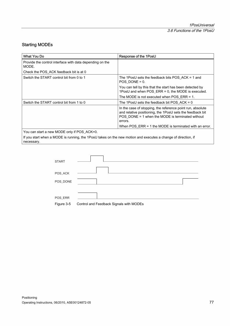
1PosUniversal 3.6 Functions of the 1PosU
Positioning Operating Instructions, 06/2010, A5E00124872-05 77
Starting MODEs What You Do Response of the 1PosU Provide the control interface with data depending on the MODE. Check the POS_ACK feedback bit is at 0
Switch the START control bit from 0 to 1 The 1PosU sets the feedback bits POS_ACK = 1 and POS_DONE = 0. You can tell by this that the start has been detected by 1PosU and when POS_ERR = 0, the MODE is executed. The MODE is not executed when POS_ERR = 1.
Switch the START control bit from 1 to 0 The 1PosU sets the feedback bit POS_ACK = 0 In the case of stopping, the reference point run, absolute
and relative positioning, the 1PosU sets the feedback bit POS_DONE = 1 when the MODE is terminated without errors. When POS_ERR = 1 the MODE is terminated with an error.
You can start a new MODE only if POS_ACK=0. If you start when a MODE is running, the 1PosU takes on the new motion and executes a change of direction, if necessary.
Figure 3-5 Control and Feedback Signals with MODEs
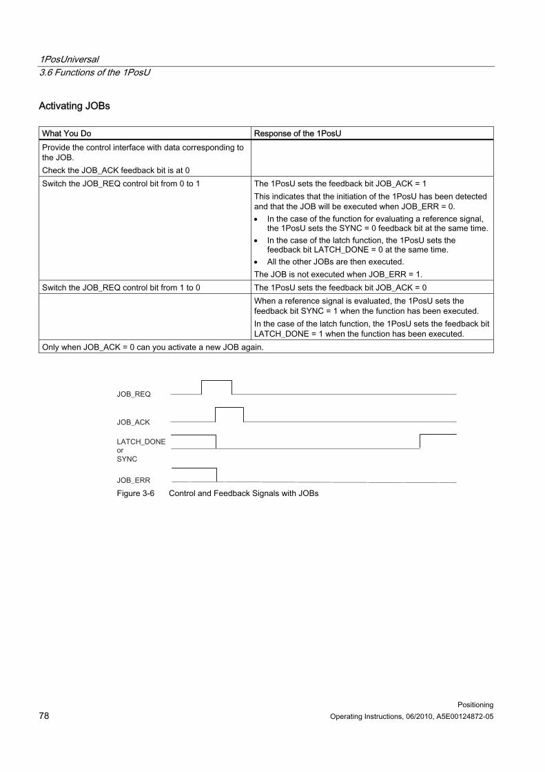
1PosUniversal 3.6 Functions of the 1PosU
Positioning 78 Operating Instructions, 06/2010, A5E00124872-05
Activating JOBs What You Do Response of the 1PosU Provide the control interface with data corresponding to the JOB. Check the JOB_ACK feedback bit is at 0
Switch the JOB_REQ control bit from 0 to 1 The 1PosU sets the feedback bit JOB_ACK = 1 This indicates that the initiation of the 1PosU has been detected and that the JOB will be executed when JOB_ERR = 0. In the case of the function for evaluating a reference signal,
the 1PosU sets the SYNC = 0 feedback bit at the same time. In the case of the latch function, the 1PosU sets the
feedback bit LATCH_DONE = 0 at the same time. All the other JOBs are then executed. The JOB is not executed when JOB_ERR = 1.
Switch the JOB_REQ control bit from 1 to 0 The 1PosU sets the feedback bit JOB_ACK = 0 When a reference signal is evaluated, the 1PosU sets the
feedback bit SYNC = 1 when the function has been executed. In the case of the latch function, the 1PosU sets the feedback bit LATCH_DONE = 1 when the function has been executed.
Only when JOB_ACK = 0 can you activate a new JOB again.
Figure 3-6 Control and Feedback Signals with JOBs
1PosUniversal 3.6 Functions of the 1PosU
Positioning Operating Instructions, 06/2010, A5E00124872-05 79
3.6.2 Axis, Drive and Encoder
Evaluation of the Encoder Signals The 1PosU evaluates the signals supplied by the position encoder differently depending on the position encoder type: SSI encoder: The 1PosU evaluates the encoder value supplied by the SSI encoder directly in increments and forms the actual value in increments (actual value = encoder value). The actual value lies in the encoder range from 0-(number of rotations * number of increments)-1. The 1PosU generates an overrun or underrun of the actual value at the limits of the operating range. Incremental encoder: The 1PosU evaluates the pulses supplied by the position encoder four times and adds them up direction-specifically to form the actual value. You must take the quadruple evaluation into account when you make settings for paths in the parameters and in the control and feedback interfaces: 1 pulse of the incremental encoder corresponds to 4 increments of the 1PosU. The current value is in the operating range 0 - 16 777 215 increments. The 1PosU generates an overrun or underrun of the actual value at the limits of the operating range. Incremental encoder at dosing operation: The 1PosU only evaluates the rising edges of the "Track A" signal and adds them up to form the actual value. The current value is in the operating range 0 - 16 777 215 increments. The 1PosU creates an overflow of the actual value at the upper limit of the operating range.
Reversal of the direction of rotation You can use the parameter for the reversal of the direction of rotation to adapt the direction of rotation of the encoder to that of the drive and the axis. In dosing operation reversal of the direction of rotation is not possible.
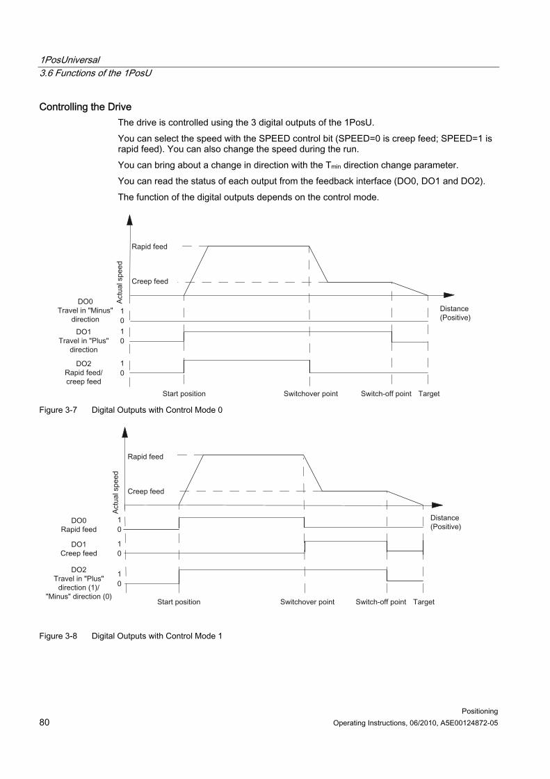
1PosUniversal 3.6 Functions of the 1PosU
Positioning 80 Operating Instructions, 06/2010, A5E00124872-05
Controlling the Drive The drive is controlled using the 3 digital outputs of the 1PosU. You can select the speed with the SPEED control bit (SPEED=0 is creep feed; SPEED=1 is rapid feed). You can also change the speed during the run. You can bring about a change in direction with the Tmin direction change parameter. You can read the status of each output from the feedback interface (DO0, DO1 and DO2). The function of the digital outputs depends on the control mode.
Figure 3-7 Digital Outputs with Control Mode 0
Figure 3-8 Digital Outputs with Control Mode 1
1PosUniversal 3.6 Functions of the 1PosU
Positioning Operating Instructions, 06/2010, A5E00124872-05 81
Parameters Meaning Value range Default setting Drive Control mode Type 0 means:
DO0 travel minus DO1 travel plus DO2 rapid/creep feed Type 1 means: DO0 rapid feed DO1 creep feed (rapid feed is 0) DO2 travel plus (1)/minus (0)
0 1
0
Tmin direction change The digital outputs are switched off, and a change of direction by Tmin is executed with a delay. Tmin is effective at each change of direction during a run. Tmin is not effective at startup after POS_DONE = 1 or POS_ERR = 1. Your input value is multiplied by 10. You thus specify Tmin in increments of 10 ms (for example, 0 ms, 10 ms or 2550 ms)
0 - 255 0
Effect of the Hardware Limit Switches The two digital inputs (DI0 and DI1) are evaluated by the 1PosU as limit switches: DI0 is the minus limit switch and limits the operating range in the minus direction. DI1 is the plus limit switch and limits the operating range in the plus direction. You can assign parameters to the hardware limit switches separately as break contacts or make contacts. The hardware limit switches are evaluated with linear axes and rotary axes. Only the hardware limit switch that lies in the direction in which the drive is being moved is evaluated. This enables you to move away from a hardware limit switch without additional error acknowledgment by moving in the other direction if you reach or overrun a hardware limit switch. The current signal level of the digital inputs is displayed in the feedback interface, delayed by the update rate.
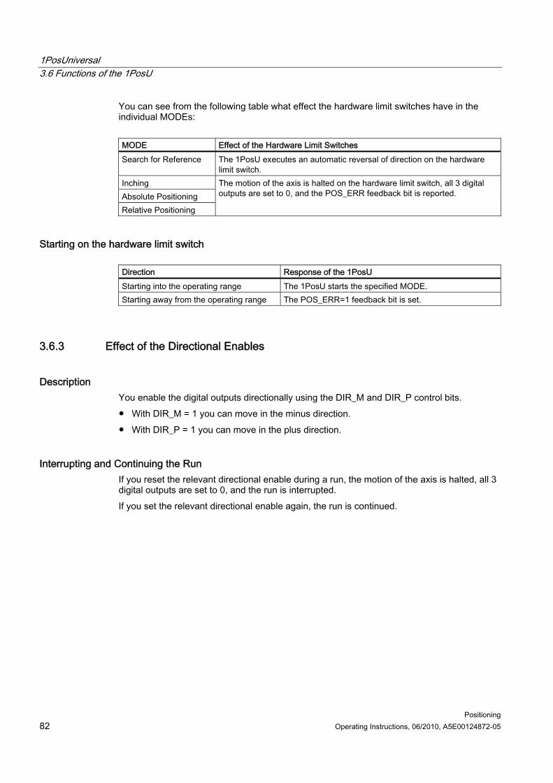
1PosUniversal 3.6 Functions of the 1PosU
Positioning 82 Operating Instructions, 06/2010, A5E00124872-05
You can see from the following table what effect the hardware limit switches have in the individual MODEs: MODE Effect of the Hardware Limit Switches Search for Reference The 1PosU executes an automatic reversal of direction on the hardware
limit switch. Inching Absolute Positioning Relative Positioning
The motion of the axis is halted on the hardware limit switch, all 3 digital outputs are set to 0, and the POS_ERR feedback bit is reported.
Starting on the hardware limit switch Direction Response of the 1PosU Starting into the operating range The 1PosU starts the specified MODE. Starting away from the operating range The POS_ERR=1 feedback bit is set.
3.6.3 Effect of the Directional Enables
Description You enable the digital outputs directionally using the DIR_M and DIR_P control bits. With DIR_M = 1 you can move in the minus direction. With DIR_P = 1 you can move in the plus direction.
Interrupting and Continuing the Run If you reset the relevant directional enable during a run, the motion of the axis is halted, all 3 digital outputs are set to 0, and the run is interrupted. If you set the relevant directional enable again, the run is continued.
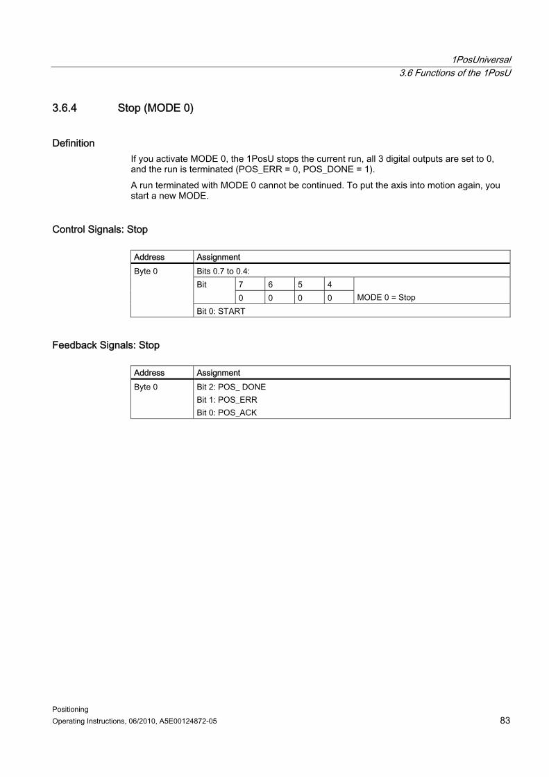
1PosUniversal 3.6 Functions of the 1PosU
Positioning Operating Instructions, 06/2010, A5E00124872-05 83
3.6.4 Stop (MODE 0)
Definition If you activate MODE 0, the 1PosU stops the current run, all 3 digital outputs are set to 0, and the run is terminated (POS_ERR = 0, POS_DONE = 1). A run terminated with MODE 0 cannot be continued. To put the axis into motion again, you start a new MODE.
Control Signals: Stop Address Assignment
Bits 0.7 to 0.4: 7 6 5 4 Bit 0 0 0 0
MODE 0 = Stop
Byte 0
Bit 0: START
Feedback Signals: Stop Address Assignment Byte 0 Bit 2: POS_ DONE
Bit 1: POS_ERR Bit 0: POS_ACK
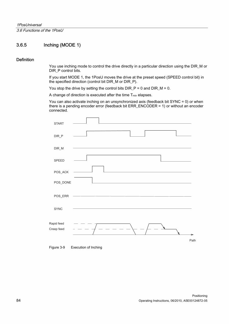
1PosUniversal 3.6 Functions of the 1PosU
Positioning 84 Operating Instructions, 06/2010, A5E00124872-05
3.6.5 Inching (MODE 1)
Definition You use inching mode to control the drive directly in a particular direction using the DIR_M or DIR_P control bits. If you start MODE 1, the 1PosU moves the drive at the preset speed (SPEED control bit) in the specified direction (control bit DIR_M or DIR_P). You stop the drive by setting the control bits DIR_P = 0 and DIR_M = 0. A change of direction is executed after the time Tmin elapses. You can also activate inching on an unsynchronized axis (feedback bit SYNC = 0) or when there is a pending encoder error (feedback bit ERR_ENCODER = 1) or without an encoder connected.
SPEED
DIR_P
POS_ERR
POS_DONE
POS_ACK
DIR_M
SYNC
START
Rapid feed
Creep feed
Path Figure 3-9 Execution of Inching
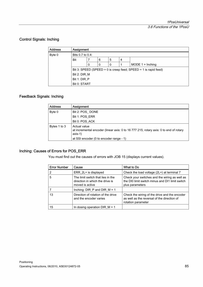
1PosUniversal 3.6 Functions of the 1PosU
Positioning Operating Instructions, 06/2010, A5E00124872-05 85
Control Signals: Inching Address Assignment
Bits 0.7 to 0.4: 7 6 5 4 Bit 0 0 0 1
MODE 1 = Inching
Byte 0
Bit 3: SPEED (SPEED = 0 is creep feed; SPEED = 1 is rapid feed) Bit 2: DIR_M Bit 1: DIR_P Bit 0: START
Feedback Signals: Inching Address Assignment Byte 0 Bit 2: POS_ DONE
Bit 1: POS_ERR Bit 0: POS_ACK
Bytes 1 to 3 Actual value at incremental encoder (linear axis: 0 to 16 777 215; rotary axis: 0 to end of rotary axis-1) at SSI encoder (0 to encoder range - 1)
Inching: Causes of Errors for POS_ERR You must find out the causes of errors with JOB 15 (displays current values). Error Number Cause What to Do 2 ERR_2L+ is displayed Check the load voltage (2L+) at terminal 7 5 The limit switch that lies in the
direction in which the drive is moved is active
Check your switches and the wiring as well as the DI0 limit switch minus and DI1 limit switch plus parameters
7 Inching: DIR_P and DIR_M = 1 13 Direction of rotation of the drive
and the encoder varies Check the wiring of the drive and the encoder as well as the reversal of the direction of rotation parameter
15 In dosing operation DIR_M = 1
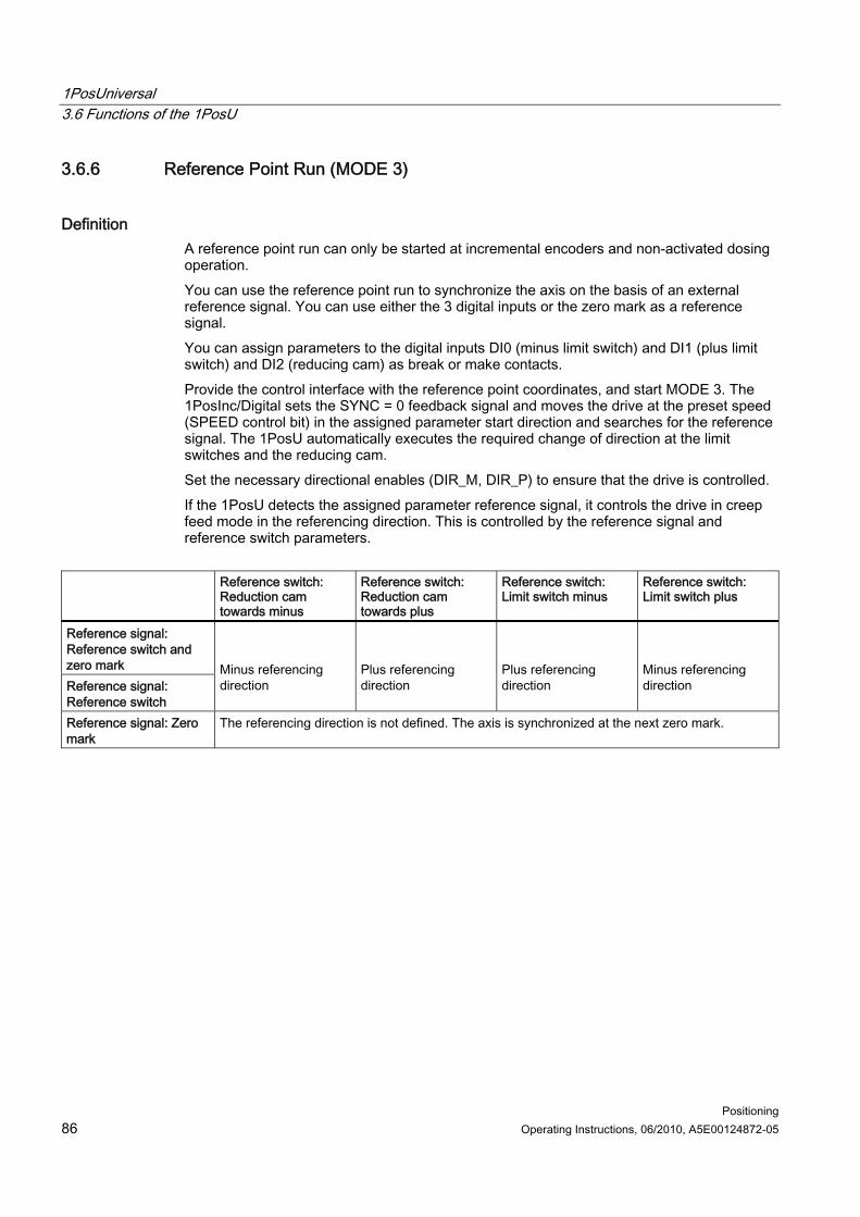
1PosUniversal 3.6 Functions of the 1PosU
Positioning 86 Operating Instructions, 06/2010, A5E00124872-05
3.6.6 Reference Point Run (MODE 3)
Definition A reference point run can only be started at incremental encoders and non-activated dosing operation. You can use the reference point run to synchronize the axis on the basis of an external reference signal. You can use either the 3 digital inputs or the zero mark as a reference signal. You can assign parameters to the digital inputs DI0 (minus limit switch) and DI1 (plus limit switch) and DI2 (reducing cam) as break or make contacts. Provide the control interface with the reference point coordinates, and start MODE 3. The 1PosInc/Digital sets the SYNC = 0 feedback signal and moves the drive at the preset speed (SPEED control bit) in the assigned parameter start direction and searches for the reference signal. The 1PosU automatically executes the required change of direction at the limit switches and the reducing cam. Set the necessary directional enables (DIR_M, DIR_P) to ensure that the drive is controlled. If the 1PosU detects the assigned parameter reference signal, it controls the drive in creep feed mode in the referencing direction. This is controlled by the reference signal and reference switch parameters.
Reference switch:
Reduction cam towards minus
Reference switch: Reduction cam towards plus
Reference switch: Limit switch minus
Reference switch: Limit switch plus
Reference signal: Reference switch and zero mark Reference signal: Reference switch
Minus referencing direction
Plus referencing direction
Plus referencing direction
Minus referencing direction
Reference signal: Zero mark
The referencing direction is not defined. The axis is synchronized at the next zero mark.
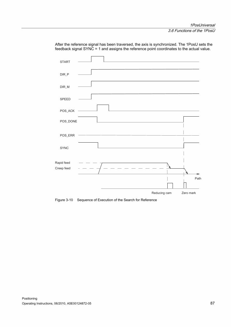
1PosUniversal 3.6 Functions of the 1PosU
Positioning Operating Instructions, 06/2010, A5E00124872-05 87
After the reference signal has been traversed, the axis is synchronized. The 1PosU sets the feedback signal SYNC = 1 and assigns the reference point coordinates to the actual value.
Figure 3-10 Sequence of Execution of the Search for Reference
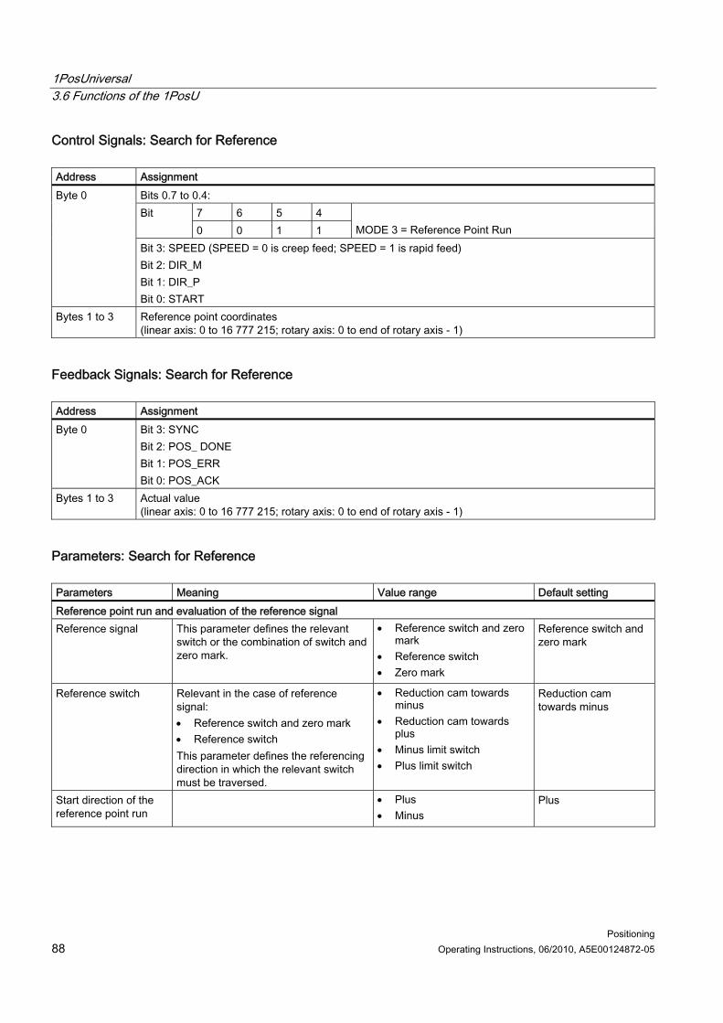
1PosUniversal 3.6 Functions of the 1PosU
Positioning 88 Operating Instructions, 06/2010, A5E00124872-05
Control Signals: Search for Reference Address Assignment
Bits 0.7 to 0.4: 7 6 5 4 Bit 0 0 1 1
MODE 3 = Reference Point Run
Byte 0
Bit 3: SPEED (SPEED = 0 is creep feed; SPEED = 1 is rapid feed) Bit 2: DIR_M Bit 1: DIR_P Bit 0: START
Bytes 1 to 3 Reference point coordinates (linear axis: 0 to 16 777 215; rotary axis: 0 to end of rotary axis - 1)
Feedback Signals: Search for Reference Address Assignment Byte 0 Bit 3: SYNC
Bit 2: POS_ DONE Bit 1: POS_ERR Bit 0: POS_ACK
Bytes 1 to 3 Actual value (linear axis: 0 to 16 777 215; rotary axis: 0 to end of rotary axis - 1)
Parameters: Search for Reference Parameters Meaning Value range Default setting Reference point run and evaluation of the reference signal Reference signal This parameter defines the relevant
switch or the combination of switch and zero mark.
Reference switch and zero mark
Reference switch Zero mark
Reference switch and zero mark
Reference switch Relevant in the case of reference signal: Reference switch and zero mark Reference switch This parameter defines the referencing direction in which the relevant switch must be traversed.
Reduction cam towards minus
Reduction cam towards plus
Minus limit switch Plus limit switch
Reduction cam towards minus
Start direction of the reference point run
Plus Minus
Plus
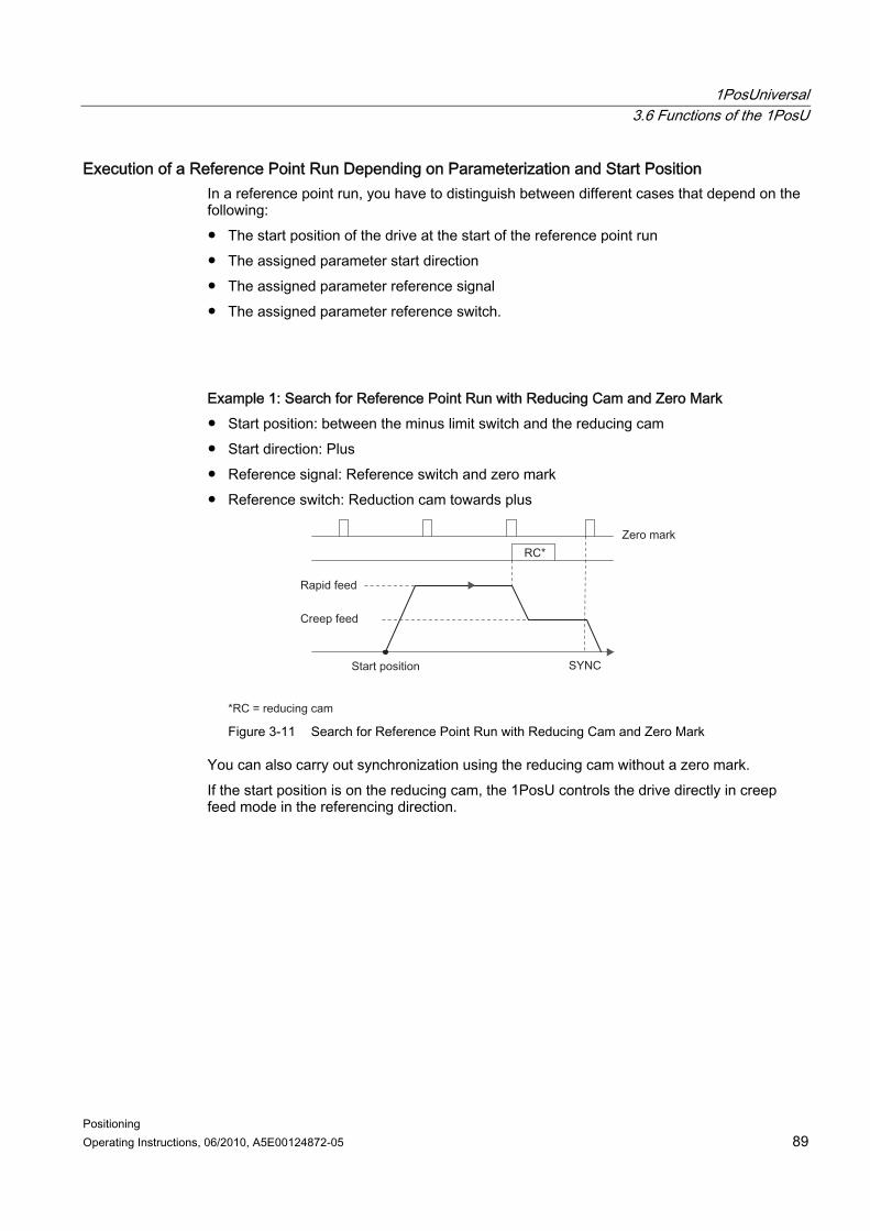
1PosUniversal 3.6 Functions of the 1PosU
Positioning Operating Instructions, 06/2010, A5E00124872-05 89
Execution of a Reference Point Run Depending on Parameterization and Start Position In a reference point run, you have to distinguish between different cases that depend on the following: The start position of the drive at the start of the reference point run The assigned parameter start direction The assigned parameter reference signal The assigned parameter reference switch.
Example 1: Search for Reference Point Run with Reducing Cam and Zero Mark Start position: between the minus limit switch and the reducing cam Start direction: Plus Reference signal: Reference switch and zero mark Reference switch: Reduction cam towards plus
Figure 3-11 Search for Reference Point Run with Reducing Cam and Zero Mark
You can also carry out synchronization using the reducing cam without a zero mark. If the start position is on the reducing cam, the 1PosU controls the drive directly in creep feed mode in the referencing direction.
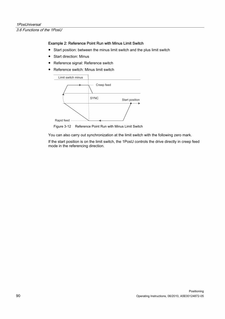
1PosUniversal 3.6 Functions of the 1PosU
Positioning 90 Operating Instructions, 06/2010, A5E00124872-05
Example 2: Reference Point Run with Minus Limit Switch Start position: between the minus limit switch and the plus limit switch Start direction: Minus Reference signal: Reference switch Reference switch: Minus limit switch
Figure 3-12 Reference Point Run with Minus Limit Switch
You can also carry out synchronization at the limit switch with the following zero mark. If the start position is on the limit switch, the 1PosU controls the drive directly in creep feed mode in the referencing direction.
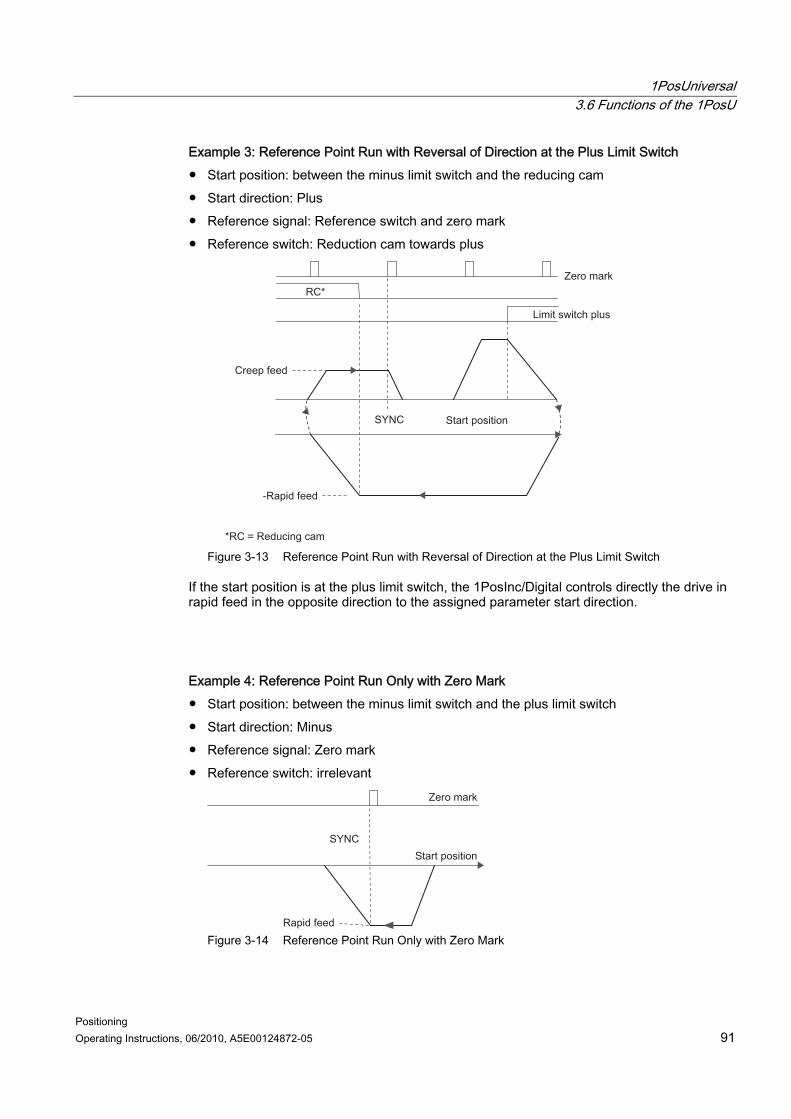
1PosUniversal 3.6 Functions of the 1PosU
Positioning Operating Instructions, 06/2010, A5E00124872-05 91
Example 3: Reference Point Run with Reversal of Direction at the Plus Limit Switch Start position: between the minus limit switch and the reducing cam Start direction: Plus Reference signal: Reference switch and zero mark Reference switch: Reduction cam towards plus
Figure 3-13 Reference Point Run with Reversal of Direction at the Plus Limit Switch
If the start position is at the plus limit switch, the 1PosInc/Digital controls directly the drive in rapid feed in the opposite direction to the assigned parameter start direction.
Example 4: Reference Point Run Only with Zero Mark Start position: between the minus limit switch and the plus limit switch Start direction: Minus Reference signal: Zero mark Reference switch: irrelevant
Figure 3-14 Reference Point Run Only with Zero Mark
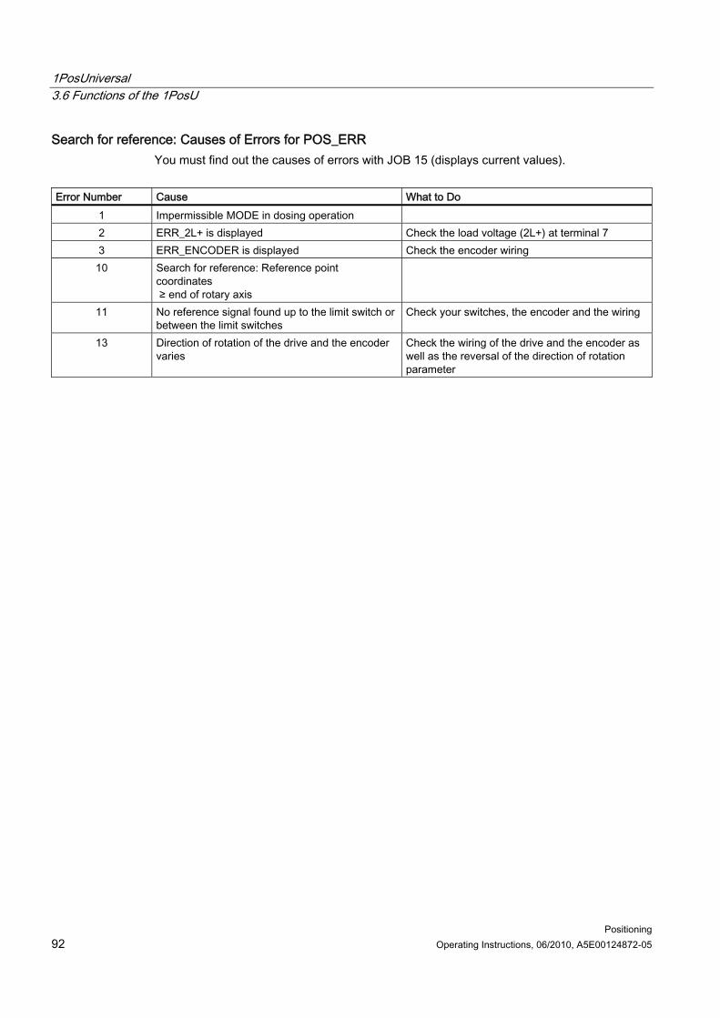
1PosUniversal 3.6 Functions of the 1PosU
Positioning 92 Operating Instructions, 06/2010, A5E00124872-05
Search for reference: Causes of Errors for POS_ERR You must find out the causes of errors with JOB 15 (displays current values).
Error Number Cause What to Do
1 Impermissible MODE in dosing operation 2 ERR_2L+ is displayed Check the load voltage (2L+) at terminal 7 3 ERR_ENCODER is displayed Check the encoder wiring
10 Search for reference: Reference point coordinates ≥ end of rotary axis
11 No reference signal found up to the limit switch or between the limit switches
Check your switches, the encoder and the wiring
13 Direction of rotation of the drive and the encoder varies
Check the wiring of the drive and the encoder as well as the reversal of the direction of rotation parameter
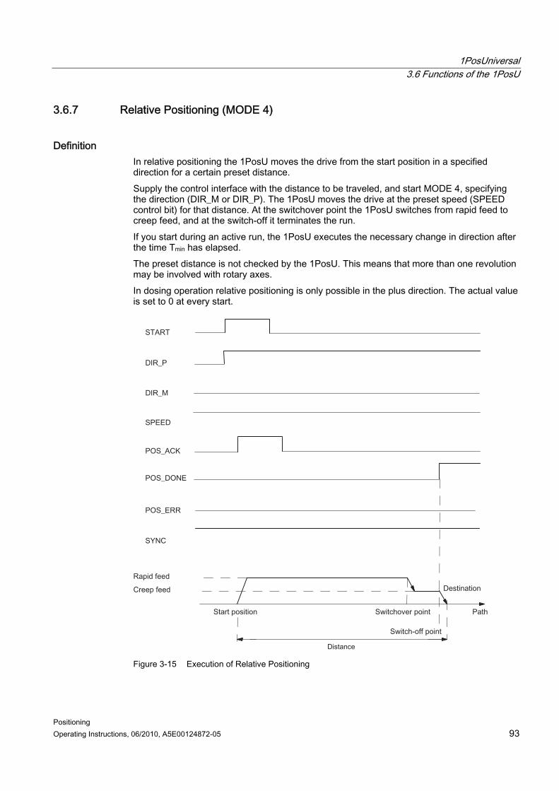
1PosUniversal 3.6 Functions of the 1PosU
Positioning Operating Instructions, 06/2010, A5E00124872-05 93
3.6.7 Relative Positioning (MODE 4)
Definition In relative positioning the 1PosU moves the drive from the start position in a specified direction for a certain preset distance. Supply the control interface with the distance to be traveled, and start MODE 4, specifying the direction (DIR_M or DIR_P). The 1PosU moves the drive at the preset speed (SPEED control bit) for that distance. At the switchover point the 1PosU switches from rapid feed to creep feed, and at the switch-off it terminates the run. If you start during an active run, the 1PosU executes the necessary change in direction after the time Tmin has elapsed. The preset distance is not checked by the 1PosU. This means that more than one revolution may be involved with rotary axes. In dosing operation relative positioning is only possible in the plus direction. The actual value is set to 0 at every start.
Figure 3-15 Execution of Relative Positioning
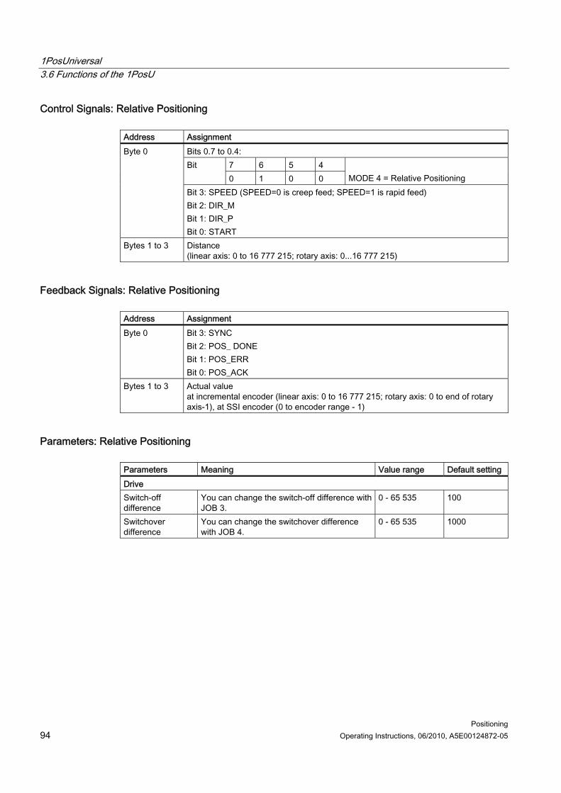
1PosUniversal 3.6 Functions of the 1PosU
Positioning 94 Operating Instructions, 06/2010, A5E00124872-05
Control Signals: Relative Positioning Address Assignment
Bits 0.7 to 0.4: 7 6 5 4 Bit 0 1 0 0
MODE 4 = Relative Positioning
Byte 0
Bit 3: SPEED (SPEED=0 is creep feed; SPEED=1 is rapid feed) Bit 2: DIR_M Bit 1: DIR_P Bit 0: START
Bytes 1 to 3 Distance (linear axis: 0 to 16 777 215; rotary axis: 0...16 777 215)
Feedback Signals: Relative Positioning Address Assignment Byte 0 Bit 3: SYNC
Bit 2: POS_ DONE Bit 1: POS_ERR Bit 0: POS_ACK
Bytes 1 to 3 Actual value at incremental encoder (linear axis: 0 to 16 777 215; rotary axis: 0 to end of rotary axis-1), at SSI encoder (0 to encoder range - 1)
Parameters: Relative Positioning Parameters Meaning Value range Default setting Drive Switch-off difference
You can change the switch-off difference with JOB 3.
0 - 65 535 100
Switchover difference
You can change the switchover difference with JOB 4.
0 - 65 535 1000
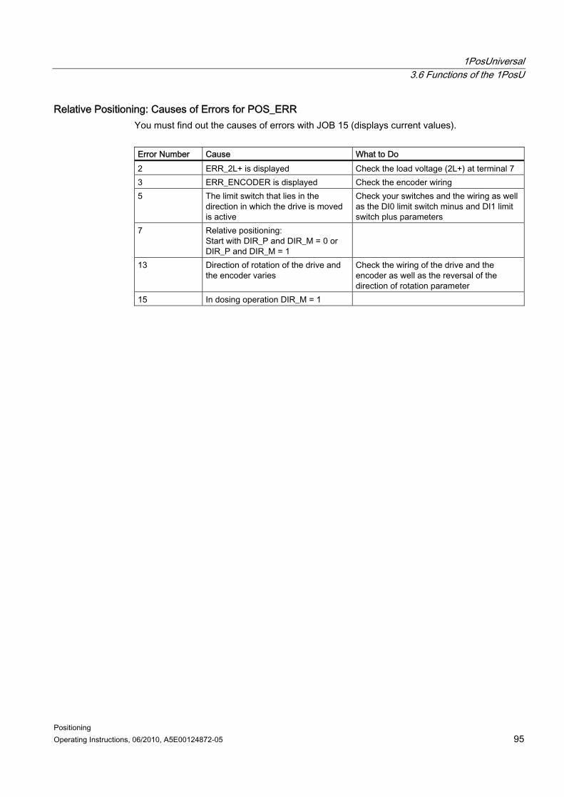
1PosUniversal 3.6 Functions of the 1PosU
Positioning Operating Instructions, 06/2010, A5E00124872-05 95
Relative Positioning: Causes of Errors for POS_ERR You must find out the causes of errors with JOB 15 (displays current values). Error Number Cause What to Do 2 ERR_2L+ is displayed Check the load voltage (2L+) at terminal 7 3 ERR_ENCODER is displayed Check the encoder wiring 5 The limit switch that lies in the
direction in which the drive is moved is active
Check your switches and the wiring as well as the DI0 limit switch minus and DI1 limit switch plus parameters
7 Relative positioning: Start with DIR_P and DIR_M = 0 or DIR_P and DIR_M = 1
13 Direction of rotation of the drive and the encoder varies
Check the wiring of the drive and the encoder as well as the reversal of the direction of rotation parameter
15 In dosing operation DIR_M = 1
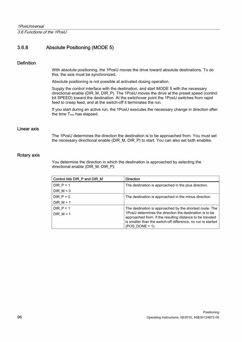
1PosUniversal 3.6 Functions of the 1PosU
Positioning 96 Operating Instructions, 06/2010, A5E00124872-05
3.6.8 Absolute Positioning (MODE 5)
Definition With absolute positioning, the 1PosU moves the drive toward absolute destinations. To do this, the axis must be synchronized. Absolute positioning is not possible at activated dosing operation. Supply the control interface with the destination, and start MODE 5 with the necessary directional enable (DIR_M, DIR_P). The 1PosU moves the drive at the preset speed (control bit SPEED) toward the destination. At the switchover point the 1PosU switches from rapid feed to creep feed, and at the switch-off it terminates the run. If you start during an active run, the 1PosU executes the necessary change in direction after the time Tmin has elapsed.
Linear axis The 1PosU determines the direction the destination is to be approached from. You must set the necessary directional enable (DIR_M, DIR_P) to start. You can also set both enables.
Rotary axis You determine the direction in which the destination is approached by selecting the directional enable (DIR_M, DIR_P): Control bits DIR_P and DIR_M Direction DIR_P = 1 DIR_M = 0
The destination is approached in the plus direction.
DIR_P = 0 DIR_M = 1
The destination is approached in the minus direction.
DIR_P = 1 DIR_M = 1
The destination is approached by the shortest route. The 1PosU determines the direction the destination is to be approached from. If the resulting distance to be traveled is smaller than the switch-off difference, no run is started (POS_DONE = 1).
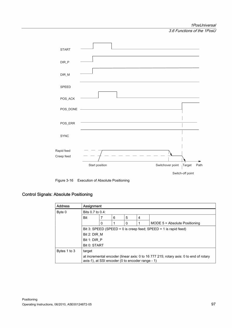
1PosUniversal 3.6 Functions of the 1PosU
Positioning Operating Instructions, 06/2010, A5E00124872-05 97
Figure 3-16 Execution of Absolute Positioning
Control Signals: Absolute Positioning Address Assignment
Bits 0.7 to 0.4: 7 6 5 4 Bit 0 1 0 1
MODE 5 = Absolute Positioning
Byte 0
Bit 3: SPEED (SPEED = 0 is creep feed; SPEED = 1 is rapid feed) Bit 2: DIR_M Bit 1: DIR_P Bit 0: START
Bytes 1 to 3 target at incremental encoder (linear axis: 0 to 16 777 215; rotary axis: 0 to end of rotary axis-1), at SSI encoder (0 to encoder range - 1)
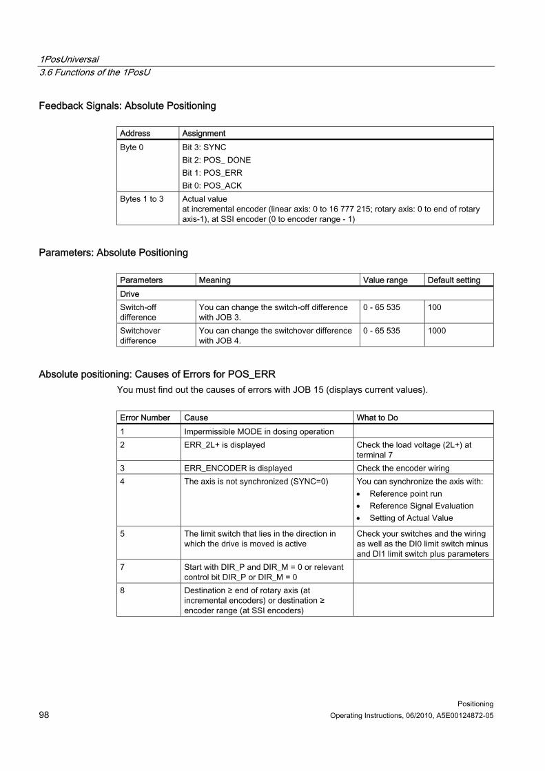
1PosUniversal 3.6 Functions of the 1PosU
Positioning 98 Operating Instructions, 06/2010, A5E00124872-05
Feedback Signals: Absolute Positioning Address Assignment Byte 0 Bit 3: SYNC
Bit 2: POS_ DONE Bit 1: POS_ERR Bit 0: POS_ACK
Bytes 1 to 3 Actual value at incremental encoder (linear axis: 0 to 16 777 215; rotary axis: 0 to end of rotary axis-1), at SSI encoder (0 to encoder range - 1)
Parameters: Absolute Positioning Parameters Meaning Value range Default setting Drive Switch-off difference
You can change the switch-off difference with JOB 3.
0 - 65 535 100
Switchover difference
You can change the switchover difference with JOB 4.
0 - 65 535 1000
Absolute positioning: Causes of Errors for POS_ERR You must find out the causes of errors with JOB 15 (displays current values). Error Number Cause What to Do 1 Impermissible MODE in dosing operation 2 ERR_2L+ is displayed Check the load voltage (2L+) at
terminal 7 3 ERR_ENCODER is displayed Check the encoder wiring 4 The axis is not synchronized (SYNC=0) You can synchronize the axis with:
Reference point run Reference Signal Evaluation Setting of Actual Value
5 The limit switch that lies in the direction in which the drive is moved is active
Check your switches and the wiring as well as the DI0 limit switch minus and DI1 limit switch plus parameters
7 Start with DIR_P and DIR_M = 0 or relevant control bit DIR_P or DIR_M = 0
8 Destination ≥ end of rotary axis (at incremental encoders) or destination ≥ encoder range (at SSI encoders)
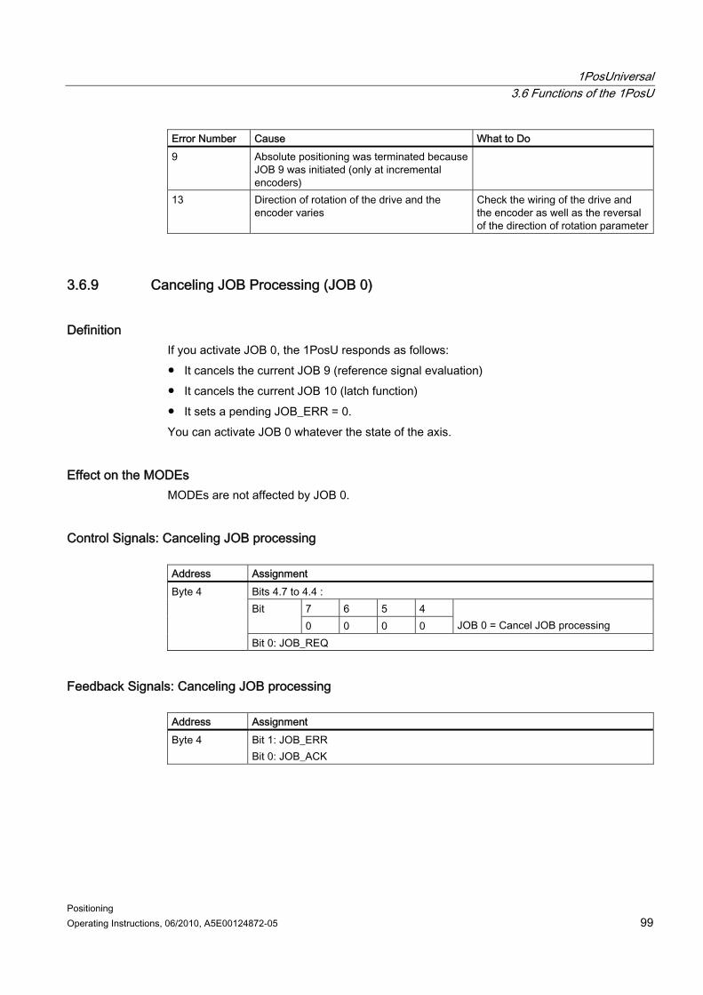
1PosUniversal 3.6 Functions of the 1PosU
Positioning Operating Instructions, 06/2010, A5E00124872-05 99
Error Number Cause What to Do 9 Absolute positioning was terminated because
JOB 9 was initiated (only at incremental encoders)
13 Direction of rotation of the drive and the encoder varies
Check the wiring of the drive and the encoder as well as the reversal of the direction of rotation parameter
3.6.9 Canceling JOB Processing (JOB 0)
Definition If you activate JOB 0, the 1PosU responds as follows: It cancels the current JOB 9 (reference signal evaluation) It cancels the current JOB 10 (latch function) It sets a pending JOB_ERR = 0. You can activate JOB 0 whatever the state of the axis.
Effect on the MODEs MODEs are not affected by JOB 0.
Control Signals: Canceling JOB processing Address Assignment
Bits 4.7 to 4.4 : 7 6 5 4 Bit 0 0 0 0
JOB 0 = Cancel JOB processing
Byte 4
Bit 0: JOB_REQ
Feedback Signals: Canceling JOB processing Address Assignment Byte 4 Bit 1: JOB_ERR
Bit 0: JOB_ACK
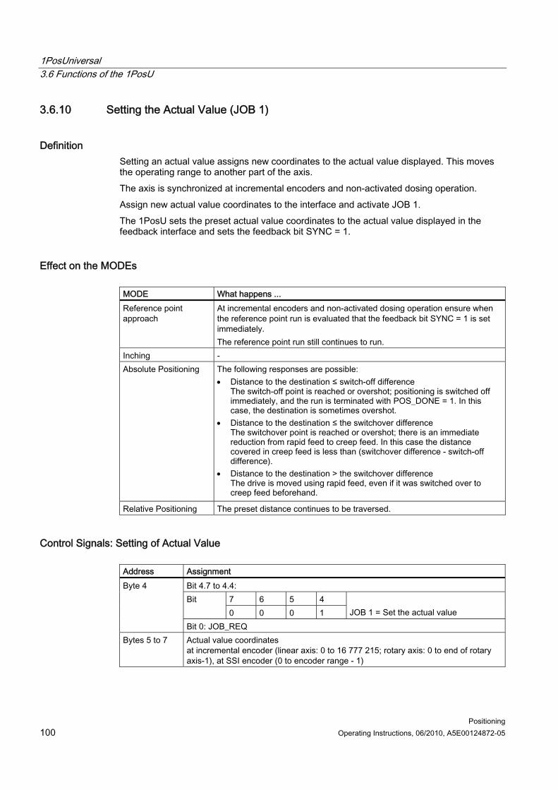
1PosUniversal 3.6 Functions of the 1PosU
Positioning 100 Operating Instructions, 06/2010, A5E00124872-05
3.6.10 Setting the Actual Value (JOB 1)
Definition Setting an actual value assigns new coordinates to the actual value displayed. This moves the operating range to another part of the axis. The axis is synchronized at incremental encoders and non-activated dosing operation. Assign new actual value coordinates to the interface and activate JOB 1. The 1PosU sets the preset actual value coordinates to the actual value displayed in the feedback interface and sets the feedback bit SYNC = 1.
Effect on the MODEs MODE What happens ... Reference point approach
At incremental encoders and non-activated dosing operation ensure when the reference point run is evaluated that the feedback bit SYNC = 1 is set immediately. The reference point run still continues to run.
Inching - Absolute Positioning The following responses are possible:
Distance to the destination ≤ switch-off difference The switch-off point is reached or overshot; positioning is switched off immediately, and the run is terminated with POS_DONE = 1. In this case, the destination is sometimes overshot.
Distance to the destination ≤ the switchover difference The switchover point is reached or overshot; there is an immediate reduction from rapid feed to creep feed. In this case the distance covered in creep feed is less than (switchover difference - switch-off difference).
Distance to the destination > the switchover difference The drive is moved using rapid feed, even if it was switched over to creep feed beforehand.
Relative Positioning The preset distance continues to be traversed.
Control Signals: Setting of Actual Value Address Assignment
Bit 4.7 to 4.4: 7 6 5 4 Bit 0 0 0 1
JOB 1 = Set the actual value
Byte 4
Bit 0: JOB_REQ Bytes 5 to 7 Actual value coordinates
at incremental encoder (linear axis: 0 to 16 777 215; rotary axis: 0 to end of rotary axis-1), at SSI encoder (0 to encoder range - 1)
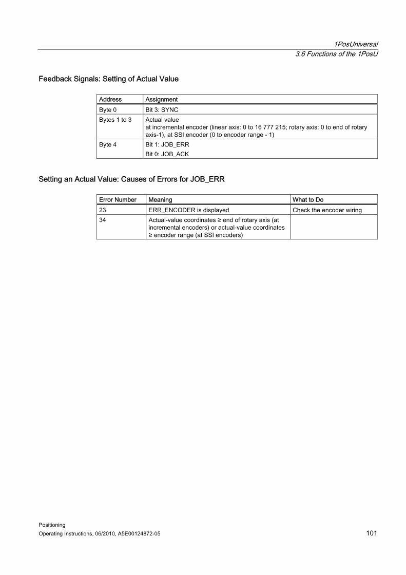
1PosUniversal 3.6 Functions of the 1PosU
Positioning Operating Instructions, 06/2010, A5E00124872-05 101
Feedback Signals: Setting of Actual Value Address Assignment Byte 0 Bit 3: SYNC Bytes 1 to 3 Actual value
at incremental encoder (linear axis: 0 to 16 777 215; rotary axis: 0 to end of rotary axis-1), at SSI encoder (0 to encoder range - 1)
Byte 4 Bit 1: JOB_ERR Bit 0: JOB_ACK
Setting an Actual Value: Causes of Errors for JOB_ERR Error Number Meaning What to Do 23 ERR_ENCODER is displayed Check the encoder wiring 34 Actual-value coordinates ≥ end of rotary axis (at
incremental encoders) or actual-value coordinates ≥ encoder range (at SSI encoders)
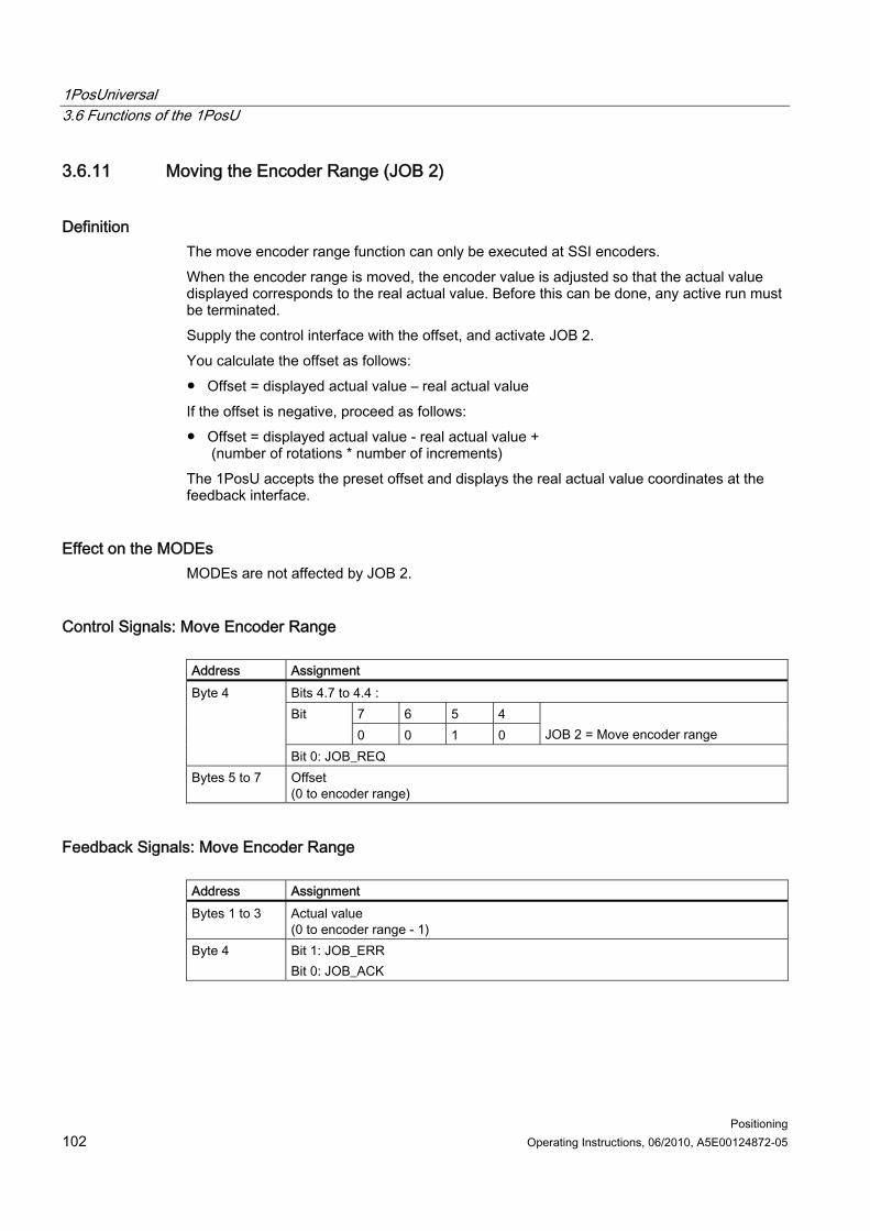
1PosUniversal 3.6 Functions of the 1PosU
Positioning 102 Operating Instructions, 06/2010, A5E00124872-05
3.6.11 Moving the Encoder Range (JOB 2)
Definition The move encoder range function can only be executed at SSI encoders. When the encoder range is moved, the encoder value is adjusted so that the actual value displayed corresponds to the real actual value. Before this can be done, any active run must be terminated. Supply the control interface with the offset, and activate JOB 2. You calculate the offset as follows: Offset = displayed actual value – real actual value If the offset is negative, proceed as follows: Offset = displayed actual value - real actual value +
(number of rotations * number of increments) The 1PosU accepts the preset offset and displays the real actual value coordinates at the feedback interface.
Effect on the MODEs MODEs are not affected by JOB 2.
Control Signals: Move Encoder Range Address Assignment
Bits 4.7 to 4.4 : 7 6 5 4 Bit 0 0 1 0
JOB 2 = Move encoder range
Byte 4
Bit 0: JOB_REQ Bytes 5 to 7 Offset
(0 to encoder range)
Feedback Signals: Move Encoder Range Address Assignment Bytes 1 to 3 Actual value
(0 to encoder range - 1) Byte 4 Bit 1: JOB_ERR
Bit 0: JOB_ACK
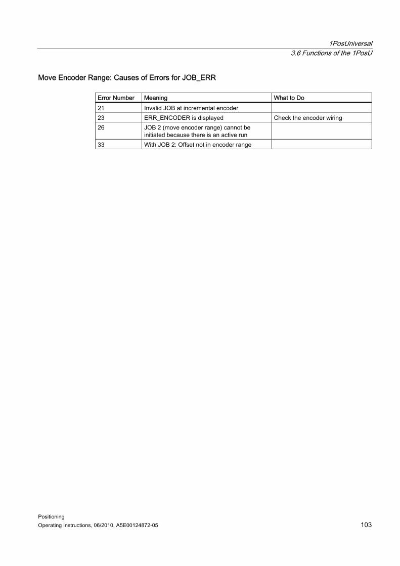
1PosUniversal 3.6 Functions of the 1PosU
Positioning Operating Instructions, 06/2010, A5E00124872-05 103
Move Encoder Range: Causes of Errors for JOB_ERR Error Number Meaning What to Do 21 Invalid JOB at incremental encoder 23 ERR_ENCODER is displayed Check the encoder wiring 26 JOB 2 (move encoder range) cannot be
initiated because there is an active run
33 With JOB 2: Offset not in encoder range
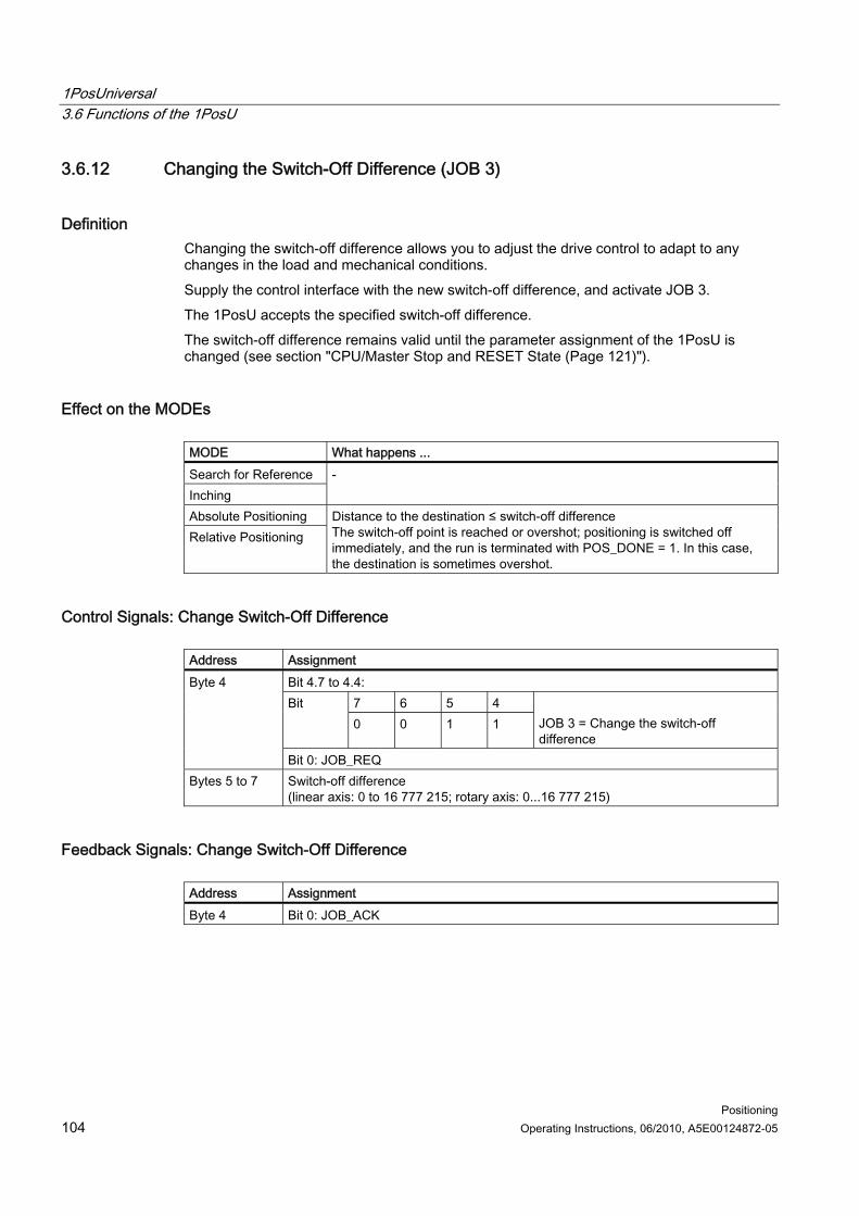
1PosUniversal 3.6 Functions of the 1PosU
Positioning 104 Operating Instructions, 06/2010, A5E00124872-05
3.6.12 Changing the Switch-Off Difference (JOB 3)
Definition Changing the switch-off difference allows you to adjust the drive control to adapt to any changes in the load and mechanical conditions. Supply the control interface with the new switch-off difference, and activate JOB 3. The 1PosU accepts the specified switch-off difference. The switch-off difference remains valid until the parameter assignment of the 1PosU is changed (see section "CPU/Master Stop and RESET State (Page 121)").
Effect on the MODEs MODE What happens ... Search for Reference Inching
-
Absolute Positioning Relative Positioning
Distance to the destination ≤ switch-off difference The switch-off point is reached or overshot; positioning is switched off immediately, and the run is terminated with POS_DONE = 1. In this case, the destination is sometimes overshot.
Control Signals: Change Switch-Off Difference Address Assignment
Bit 4.7 to 4.4: 7 6 5 4 Bit 0 0 1 1
JOB 3 = Change the switch-off difference
Byte 4
Bit 0: JOB_REQ Bytes 5 to 7 Switch-off difference
(linear axis: 0 to 16 777 215; rotary axis: 0...16 777 215)
Feedback Signals: Change Switch-Off Difference Address Assignment Byte 4 Bit 0: JOB_ACK
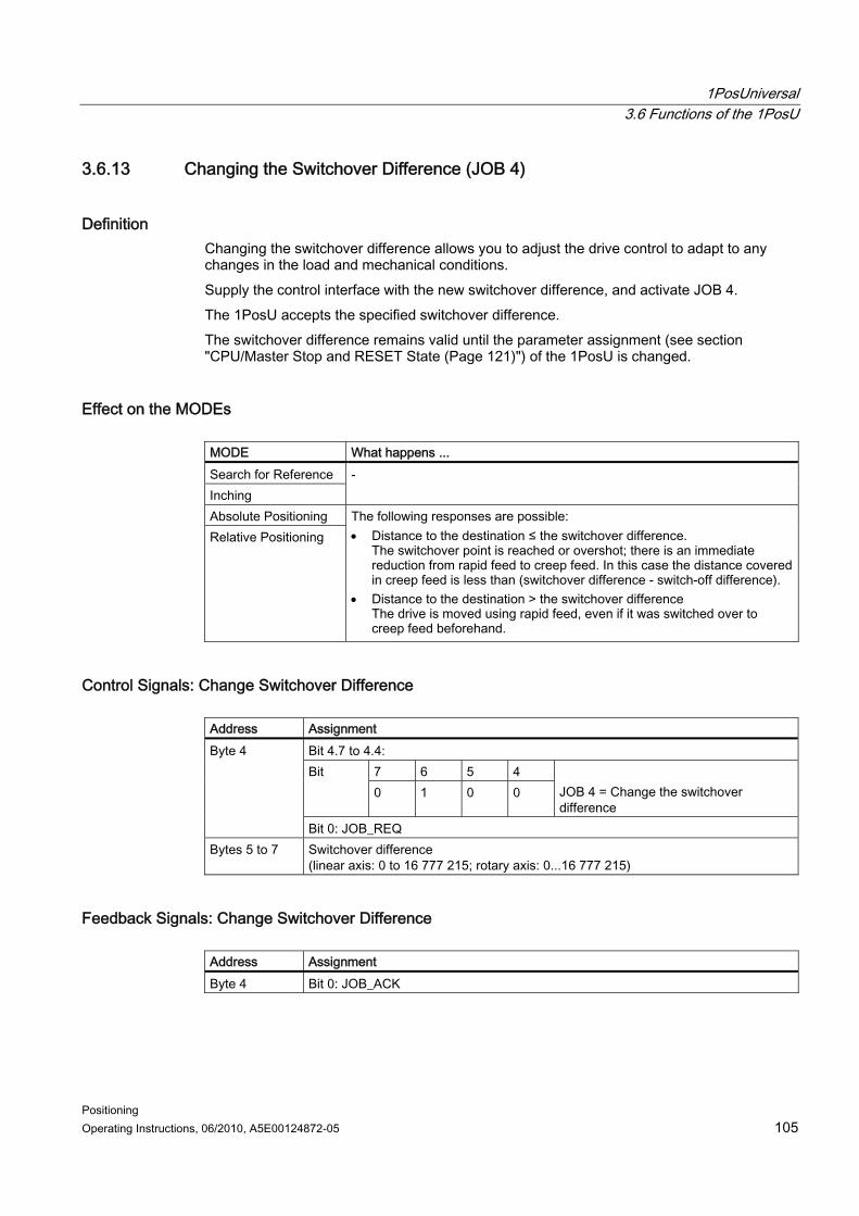
1PosUniversal 3.6 Functions of the 1PosU
Positioning Operating Instructions, 06/2010, A5E00124872-05 105
3.6.13 Changing the Switchover Difference (JOB 4)
Definition Changing the switchover difference allows you to adjust the drive control to adapt to any changes in the load and mechanical conditions. Supply the control interface with the new switchover difference, and activate JOB 4. The 1PosU accepts the specified switchover difference. The switchover difference remains valid until the parameter assignment (see section "CPU/Master Stop and RESET State (Page 121)") of the 1PosU is changed.
Effect on the MODEs MODE What happens ... Search for Reference Inching
-
Absolute Positioning Relative Positioning
The following responses are possible: Distance to the destination ≤ the switchover difference.
The switchover point is reached or overshot; there is an immediate reduction from rapid feed to creep feed. In this case the distance covered in creep feed is less than (switchover difference - switch-off difference).
Distance to the destination > the switchover difference The drive is moved using rapid feed, even if it was switched over to creep feed beforehand.
Control Signals: Change Switchover Difference Address Assignment
Bit 4.7 to 4.4: 7 6 5 4 Bit 0 1 0 0
JOB 4 = Change the switchover difference
Byte 4
Bit 0: JOB_REQ Bytes 5 to 7 Switchover difference
(linear axis: 0 to 16 777 215; rotary axis: 0...16 777 215)
Feedback Signals: Change Switchover Difference Address Assignment Byte 4 Bit 0: JOB_ACK

1PosUniversal 3.6 Functions of the 1PosU
Positioning 106 Operating Instructions, 06/2010, A5E00124872-05
3.6.14 Evaluating the Reference Signal (JOB 9)
Definition The evaluate reference signal function is only available at incremental encoders and non-active dosing operation. By evaluating the reference signal you can synchronize the axis using an external reference signal during a current run in inching or relative positioning mode. You can use either the 3 digital inputs or the zero mark as a reference signal. You can assign parameters to the digital inputs DI0 (minus limit switch) and DI1 (plus limit switch) and DI2 (reducing cam) as break or make contacts. Supply the control interface with the reference point coordinates, and activate JOB 9. The 1PosU sets the feedback signal SYNC = 0. If the 1PosInc/Digital detects the overrunning of the assigned parameter reference signal in the referencing direction, the axis is synchronized. The 1PosU sets the feedback signal SYNC = 1 and assigns the reference point coordinates to the actual value. The referencing direction is determined by the reference signal and reference switch parameters.
Reference switch:
Reduction cam towards minus
Reference switch: Reduction cam towards plus
Reference switch: Limit switch minus
Reference switch: Limit switch plus
Reference signal: Reference switch and zero mark Reference signal: Reference switch
Minus referencing direction
Plus referencing direction
Plus referencing direction
Minus referencing direction
Reference signal: Zero mark
The referencing direction is not defined. The axis is synchronized at the next zero mark.
Effect on the MODEs MODE What Happens Search for Reference The reference coordinates transferred with JOB 9 are valid Inching - Absolute Positioning Run canceled with POS_ERR = 1 because SYNC is deleted Relative Positioning -

1PosUniversal 3.6 Functions of the 1PosU
Positioning Operating Instructions, 06/2010, A5E00124872-05 107
Control Signals: Reference Signal Evaluation Address Assignment
Bits 4.7 to 4.4 : 7 6 5 4 Bit 1 0 0 1
JOB 9 = Evaluate the reference signal
Byte 4
Bit 0: JOB_REQ Bytes 5 to 7 Reference point coordinates
(linear axis: 0 to 16 777 215; rotary axis: 0 to end of rotary axis - 1)
Feedback Signals: Reference Signal Evaluation Address Assignment Byte 0 Bit 3: SYNC Bytes 1 to 3 Actual value
(linear axis: 0 to 16 777 215; rotary axis: 0 to end of rotary axis - 1) Byte 4 Bit 1: JOB_ERR
Bit 0: JOB_ACK
Parameters: Reference Signal Evaluation Parameters Meaning Value range Default setting Reference point run and evaluation of the reference signal Reference signal This parameter defines the relevant
switch or the combination of switch and zero mark.
Reference switch and zero mark
Reference switch Zero mark
Reference switch and zero mark
Reference switch Relevant in the case of reference signal: Reference switch and zero mark Reference switch This parameter defines the referencing direction in which the switch must be traversed.
Reduction cam towards minus
Reduction cam towards plus
Minus limit switch Plus limit switch
Reduction cam towards minus
Evaluating the Reference Signal: Causes of Errors for JOB_ERR Error Number Meaning What to Do
21 Impermissible JOB at SSI encoders or in dosing operation
23 ERR_ENCODER is displayed Check the encoder wiring 30 Reference point coordinates ≥ end of rotary
axis
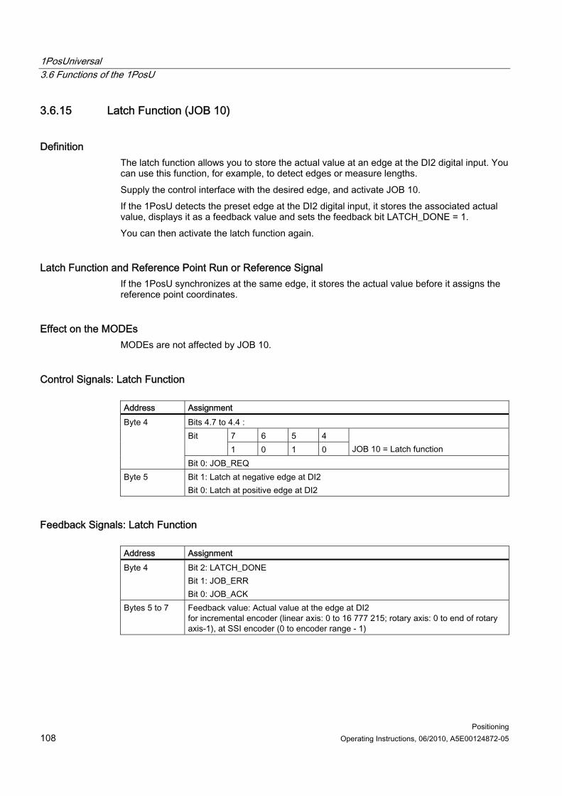
1PosUniversal 3.6 Functions of the 1PosU
Positioning 108 Operating Instructions, 06/2010, A5E00124872-05
3.6.15 Latch Function (JOB 10)
Definition The latch function allows you to store the actual value at an edge at the DI2 digital input. You can use this function, for example, to detect edges or measure lengths. Supply the control interface with the desired edge, and activate JOB 10. If the 1PosU detects the preset edge at the DI2 digital input, it stores the associated actual value, displays it as a feedback value and sets the feedback bit LATCH_DONE = 1. You can then activate the latch function again.
Latch Function and Reference Point Run or Reference Signal If the 1PosU synchronizes at the same edge, it stores the actual value before it assigns the reference point coordinates.
Effect on the MODEs MODEs are not affected by JOB 10.
Control Signals: Latch Function Address Assignment
Bits 4.7 to 4.4 : 7 6 5 4 Bit 1 0 1 0
JOB 10 = Latch function
Byte 4
Bit 0: JOB_REQ Byte 5 Bit 1: Latch at negative edge at DI2
Bit 0: Latch at positive edge at DI2
Feedback Signals: Latch Function Address Assignment Byte 4 Bit 2: LATCH_DONE
Bit 1: JOB_ERR Bit 0: JOB_ACK
Bytes 5 to 7 Feedback value: Actual value at the edge at DI2 for incremental encoder (linear axis: 0 to 16 777 215; rotary axis: 0 to end of rotary axis-1), at SSI encoder (0 to encoder range - 1)
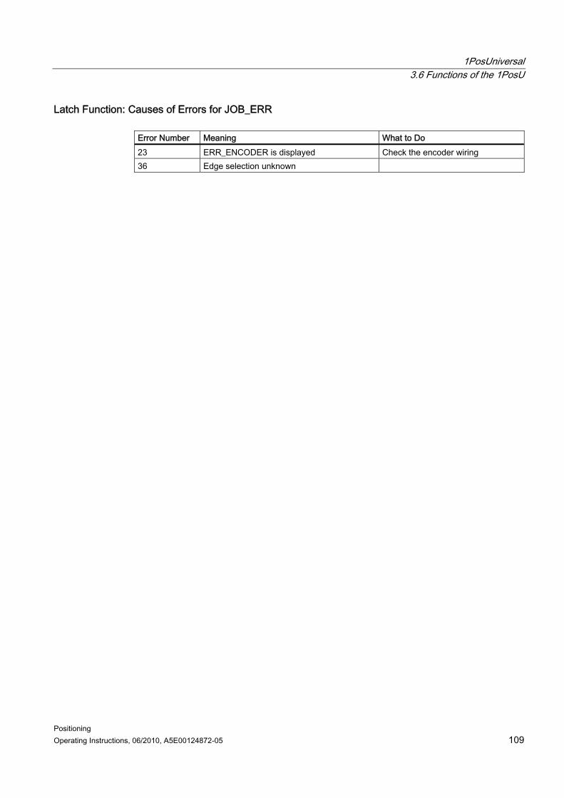
1PosUniversal 3.6 Functions of the 1PosU
Positioning Operating Instructions, 06/2010, A5E00124872-05 109
Latch Function: Causes of Errors for JOB_ERR Error Number Meaning What to Do 23 ERR_ENCODER is displayed Check the encoder wiring 36 Edge selection unknown
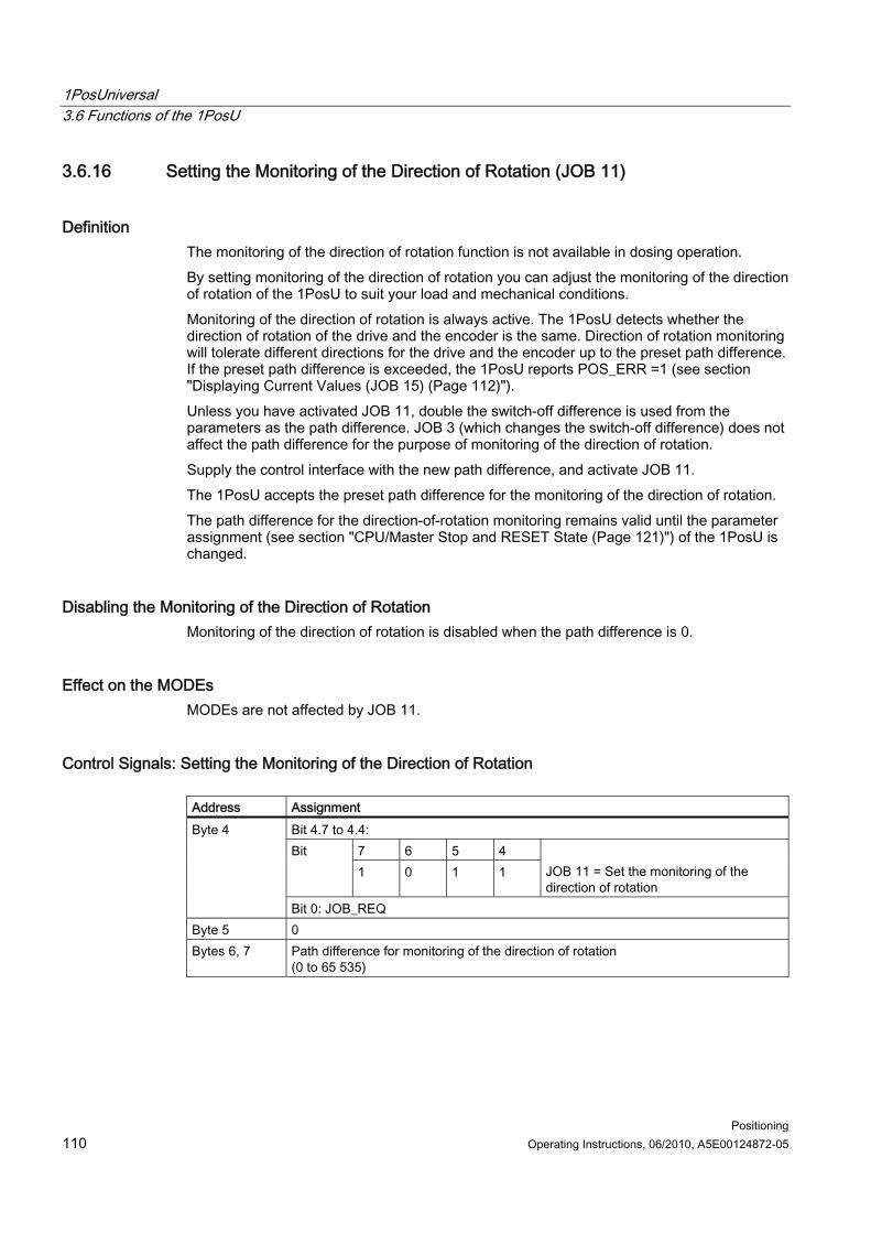
1PosUniversal 3.6 Functions of the 1PosU
Positioning 110 Operating Instructions, 06/2010, A5E00124872-05
3.6.16 Setting the Monitoring of the Direction of Rotation (JOB 11)
Definition The monitoring of the direction of rotation function is not available in dosing operation. By setting monitoring of the direction of rotation you can adjust the monitoring of the direction of rotation of the 1PosU to suit your load and mechanical conditions. Monitoring of the direction of rotation is always active. The 1PosU detects whether the direction of rotation of the drive and the encoder is the same. Direction of rotation monitoring will tolerate different directions for the drive and the encoder up to the preset path difference. If the preset path difference is exceeded, the 1PosU reports POS_ERR =1 (see section "Displaying Current Values (JOB 15) (Page 112)"). Unless you have activated JOB 11, double the switch-off difference is used from the parameters as the path difference. JOB 3 (which changes the switch-off difference) does not affect the path difference for the purpose of monitoring of the direction of rotation. Supply the control interface with the new path difference, and activate JOB 11. The 1PosU accepts the preset path difference for the monitoring of the direction of rotation. The path difference for the direction-of-rotation monitoring remains valid until the parameter assignment (see section "CPU/Master Stop and RESET State (Page 121)") of the 1PosU is changed.
Disabling the Monitoring of the Direction of Rotation Monitoring of the direction of rotation is disabled when the path difference is 0.
Effect on the MODEs MODEs are not affected by JOB 11.
Control Signals: Setting the Monitoring of the Direction of Rotation Address Assignment
Bit 4.7 to 4.4: 7 6 5 4 Bit 1 0 1 1
JOB 11 = Set the monitoring of the direction of rotation
Byte 4
Bit 0: JOB_REQ Byte 5 0 Bytes 6, 7 Path difference for monitoring of the direction of rotation
(0 to 65 535)
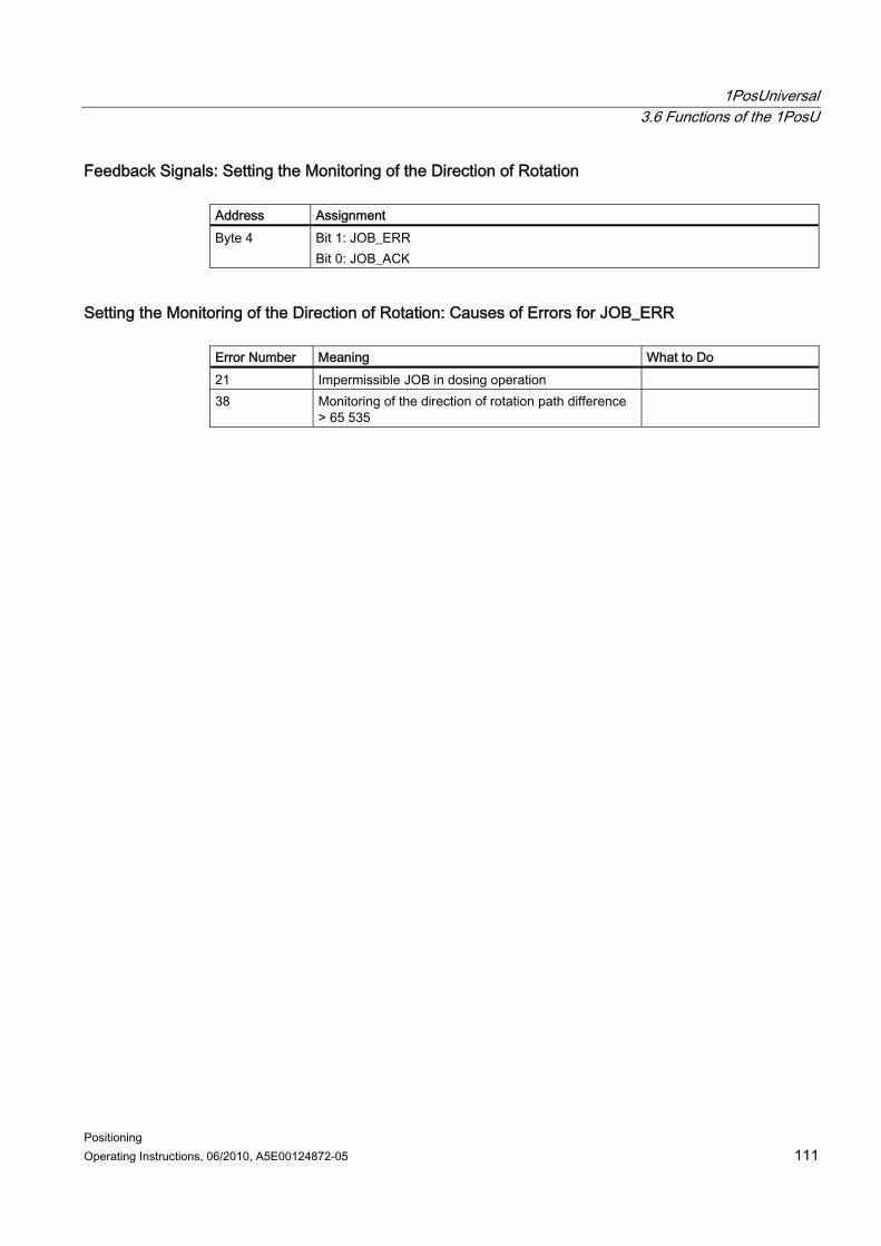
1PosUniversal 3.6 Functions of the 1PosU
Positioning Operating Instructions, 06/2010, A5E00124872-05 111
Feedback Signals: Setting the Monitoring of the Direction of Rotation Address Assignment Byte 4 Bit 1: JOB_ERR
Bit 0: JOB_ACK
Setting the Monitoring of the Direction of Rotation: Causes of Errors for JOB_ERR Error Number Meaning What to Do 21 Impermissible JOB in dosing operation 38 Monitoring of the direction of rotation path difference
> 65 535
1PosUniversal 3.6 Functions of the 1PosU
Positioning 112 Operating Instructions, 06/2010, A5E00124872-05
3.6.17 Displaying Current Values (JOB 15)
Definition You can display the following values in the feedback interface as feedback values: Residual distance Actual speed Causes of errors for POS_ERR and JOB_ERR The residual distance is set by the 1PosU as the default for the feedback value. The 1PosU continuously displays the actual value in the feedback interface irrespective of the selected feedback value. Supply the control interface with the desired feedback value and activate JOB 15. The selected feedback value remains valid until the parameter assignment (see section "CPU/Master Stop and RESET State (Page 121)") of the 1PosU is changed.
Displaying Current Values and the Latch Function If you activate the latch function, the 1PosU sets a feedback value of 0 and displays the actual value at the edge at the DI2 digital input. You can only activate JOB 15 again after the latch function has terminated.
Residual distance The 1PosU calculates the distance to the destination as the residual distance in the absolute positioning and relative positioning MODEs. As long as the actual value is before the destination, the residual distance remains positive. It becomes negative once the destination is overshot. The residual distance is 0 in the other MODEs. The 1PosU displays the residual distance with a sign between -8 388 608 and 8 388 607 increments. Negative values are displayed in twos complement. If the actual residual distance is beyond these limits, the limit value is displayed.
Actual speed The 1PosU calculates the actual speed as an encoder value change in increments per 10 ms. It displays these between 0 and 16 777 215.
Causes of errors for POS_ERR and JOB_ERR The 1PosU displays the causes of errors for POS_ERR and JOB_ERR as well as the MODE and JOB entered in the control interface.
Effect on the MODEs MODEs are not affected by JOB 15.
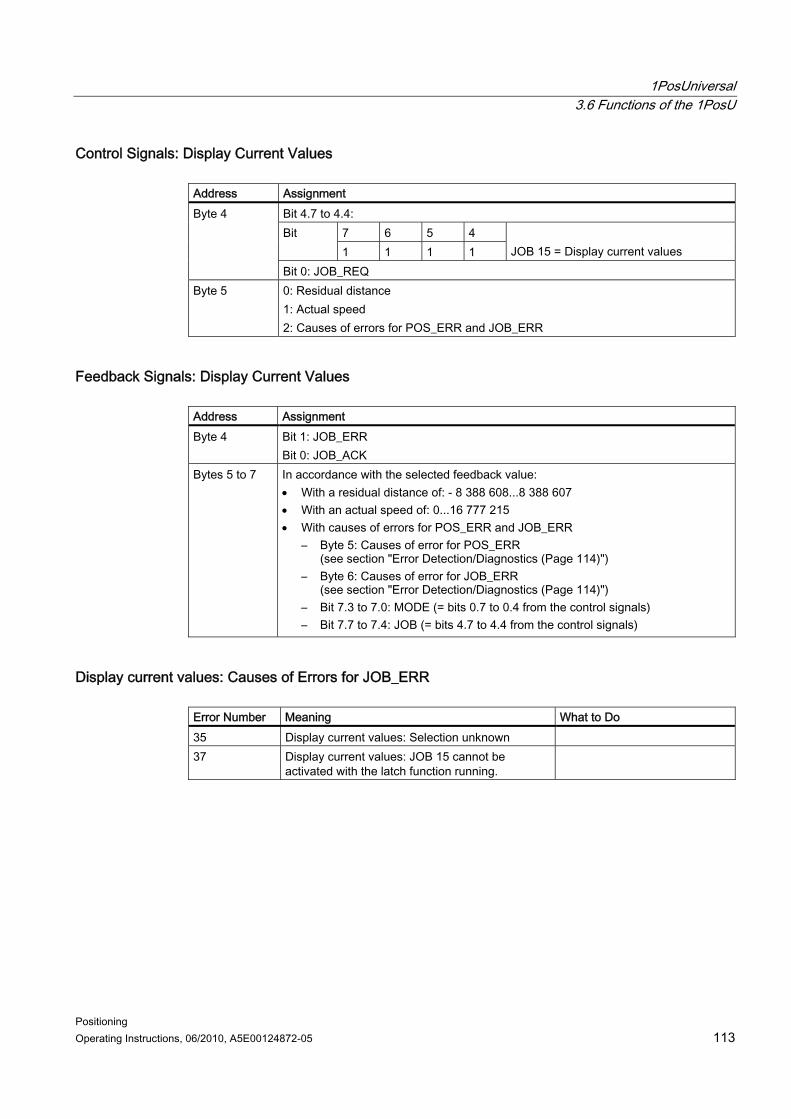
1PosUniversal 3.6 Functions of the 1PosU
Positioning Operating Instructions, 06/2010, A5E00124872-05 113
Control Signals: Display Current Values Address Assignment
Bit 4.7 to 4.4: 7 6 5 4 Bit 1 1 1 1
JOB 15 = Display current values
Byte 4
Bit 0: JOB_REQ Byte 5 0: Residual distance
1: Actual speed 2: Causes of errors for POS_ERR and JOB_ERR
Feedback Signals: Display Current Values Address Assignment Byte 4 Bit 1: JOB_ERR
Bit 0: JOB_ACK Bytes 5 to 7 In accordance with the selected feedback value:
With a residual distance of: - 8 388 608...8 388 607 With an actual speed of: 0...16 777 215 With causes of errors for POS_ERR and JOB_ERR
– Byte 5: Causes of error for POS_ERR (see section "Error Detection/Diagnostics (Page 114)")
– Byte 6: Causes of error for JOB_ERR (see section "Error Detection/Diagnostics (Page 114)")
– Bit 7.3 to 7.0: MODE (= bits 0.7 to 0.4 from the control signals) – Bit 7.7 to 7.4: JOB (= bits 4.7 to 4.4 from the control signals)
Display current values: Causes of Errors for JOB_ERR Error Number Meaning What to Do 35 Display current values: Selection unknown 37 Display current values: JOB 15 cannot be
activated with the latch function running.
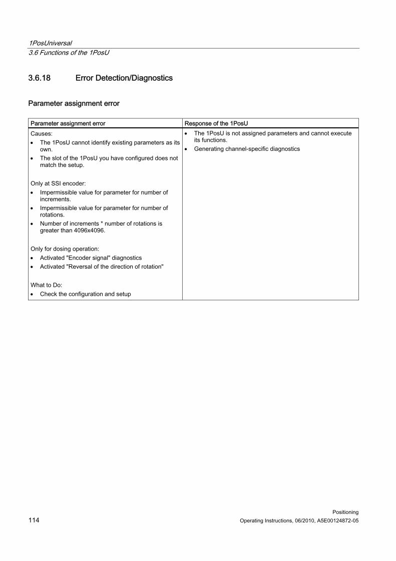
1PosUniversal 3.6 Functions of the 1PosU
Positioning 114 Operating Instructions, 06/2010, A5E00124872-05
3.6.18 Error Detection/Diagnostics
Parameter assignment error Parameter assignment error Response of the 1PosU Causes: The 1PosU cannot identify existing parameters as its
own. The slot of the 1PosU you have configured does not
match the setup. Only at SSI encoder: Impermissible value for parameter for number of
increments. Impermissible value for parameter for number of
rotations. Number of increments * number of rotations is
greater than 4096x4096. Only for dosing operation: Activated "Encoder signal" diagnostics Activated "Reversal of the direction of rotation" What to Do: Check the configuration and setup
The 1PosU is not assigned parameters and cannot execute its functions.
Generating channel-specific diagnostics
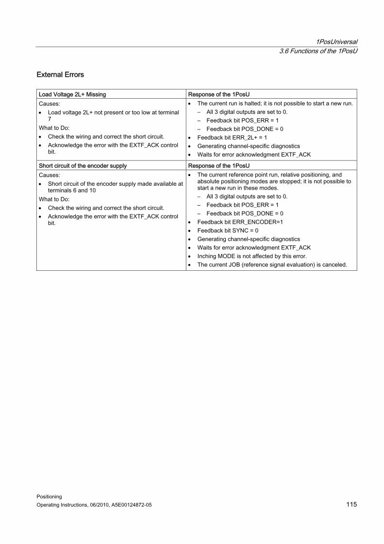
1PosUniversal 3.6 Functions of the 1PosU
Positioning Operating Instructions, 06/2010, A5E00124872-05 115
External Errors Load Voltage 2L+ Missing Response of the 1PosU Causes: Load voltage 2L+ not present or too low at terminal
7 What to Do: Check the wiring and correct the short circuit. Acknowledge the error with the EXTF_ACK control
bit.
The current run is halted; it is not possible to start a new run. – All 3 digital outputs are set to 0. – Feedback bit POS_ERR = 1 – Feedback bit POS_DONE = 0
Feedback bit ERR_2L+ = 1 Generating channel-specific diagnostics Waits for error acknowledgment EXTF_ACK
Short circuit of the encoder supply Response of the 1PosU Causes: Short circuit of the encoder supply made available at
terminals 6 and 10 What to Do: Check the wiring and correct the short circuit. Acknowledge the error with the EXTF_ACK control
bit.
The current reference point run, relative positioning, and absolute positioning modes are stopped; it is not possible to start a new run in these modes. – All 3 digital outputs are set to 0. – Feedback bit POS_ERR = 1 – Feedback bit POS_DONE = 0
Feedback bit ERR_ENCODER=1 Feedback bit SYNC = 0 Generating channel-specific diagnostics Waits for error acknowledgment EXTF_ACK Inching MODE is not affected by this error. The current JOB (reference signal evaluation) is canceled.
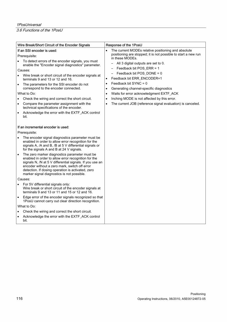
1PosUniversal 3.6 Functions of the 1PosU
Positioning 116 Operating Instructions, 06/2010, A5E00124872-05
Wire Break/Short Circuit of the Encoder Signals Response of the 1PosU If an SSI encoder is used: Prerequisite: To detect errors of the encoder signals, you must
enable the "Encoder signal diagnostics" parameter. Causes: Wire break or short circuit of the encoder signals at
terminals 9 and 13 or 12 and 16. The parameters for the SSI encoder do not
correspond to the encoder connected. What to Do: Check the wiring and correct the short circuit. Compare the parameter assignment with the
technical specifications of the encoder. Acknowledge the error with the EXTF_ACK control
bit. If an incremental encoder is used: Prerequisite: The encoder signal diagnostics parameter must be
enabled in order to allow error recognition for the signals A, /A and B, /B at 5 V differential signals or for the signals A and B at 24 V signals.
The zero marker diagnostics parameter must be enabled in order to allow error recognition for the signals N, /N at 5 V differential signals. If you use an encoder without a zero mark, switch off error detection. If dosing operation is activated, zero marker signal diagnostics is not possible.
Causes: For 5V differential signals only:
Wire break or short circuit of the encoder signals at terminals 9 and 13 or 11 and 15 or 12 and 16.
Edge error of the encoder signals recognized so that 1PosU cannot carry out clear direction recognition.
What to Do: Check the wiring and correct the short circuit. Acknowledge the error with the EXTF_ACK control
bit.
The current MODEs relative positioning and absolute positioning are stopped; it is not possible to start a new run in these MODEs. – All 3 digital outputs are set to 0. – Feedback bit POS_ERR = 1 – Feedback bit POS_DONE = 0
Feedback bit ERR_ENCODER=1 Feedback bit SYNC = 0 Generating channel-specific diagnostics Waits for error acknowledgment EXTF_ACK Inching MODE is not affected by this error. The current JOB (reference signal evaluation) is canceled.
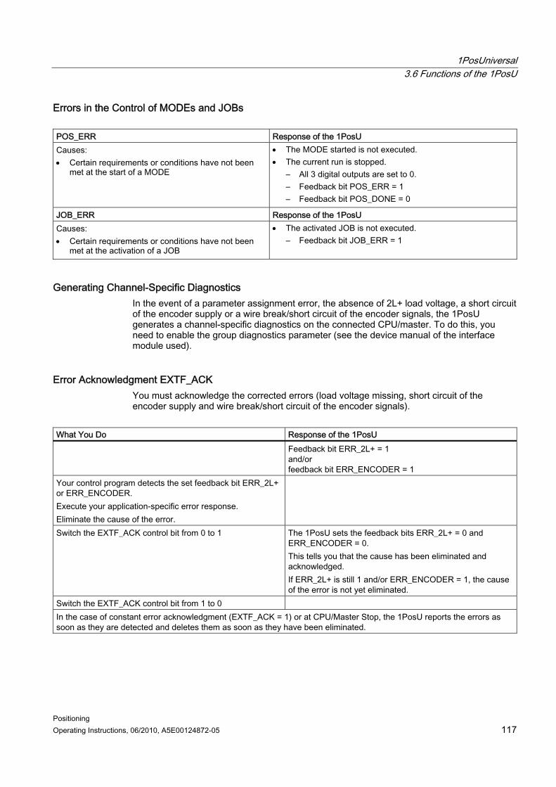
1PosUniversal 3.6 Functions of the 1PosU
Positioning Operating Instructions, 06/2010, A5E00124872-05 117
Errors in the Control of MODEs and JOBs POS_ERR Response of the 1PosU Causes: Certain requirements or conditions have not been
met at the start of a MODE
The MODE started is not executed. The current run is stopped.
– All 3 digital outputs are set to 0. – Feedback bit POS_ERR = 1 – Feedback bit POS_DONE = 0
JOB_ERR Response of the 1PosU Causes: Certain requirements or conditions have not been
met at the activation of a JOB
The activated JOB is not executed. – Feedback bit JOB_ERR = 1
Generating Channel-Specific Diagnostics In the event of a parameter assignment error, the absence of 2L+ load voltage, a short circuit of the encoder supply or a wire break/short circuit of the encoder signals, the 1PosU generates a channel-specific diagnostics on the connected CPU/master. To do this, you need to enable the group diagnostics parameter (see the device manual of the interface module used).
Error Acknowledgment EXTF_ACK You must acknowledge the corrected errors (load voltage missing, short circuit of the encoder supply and wire break/short circuit of the encoder signals).
What You Do Response of the 1PosU Feedback bit ERR_2L+ = 1
and/or feedback bit ERR_ENCODER = 1
Your control program detects the set feedback bit ERR_2L+ or ERR_ENCODER. Execute your application-specific error response. Eliminate the cause of the error.
Switch the EXTF_ACK control bit from 0 to 1 The 1PosU sets the feedback bits ERR_2L+ = 0 and ERR_ENCODER = 0. This tells you that the cause has been eliminated and acknowledged. If ERR_2L+ is still 1 and/or ERR_ENCODER = 1, the cause of the error is not yet eliminated.
Switch the EXTF_ACK control bit from 1 to 0 In the case of constant error acknowledgment (EXTF_ACK = 1) or at CPU/Master Stop, the 1PosU reports the errors as soon as they are detected and deletes them as soon as they have been eliminated.
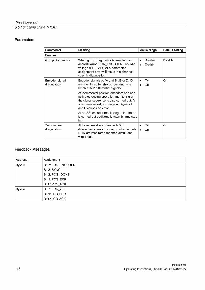
1PosUniversal 3.6 Functions of the 1PosU
Positioning 118 Operating Instructions, 06/2010, A5E00124872-05
Parameters Parameters Meaning Value range Default setting Enables Group diagnostics When group diagnostics is enabled, an
encoder error (ERR_ENCODER), no load voltage (ERR_2L+) or a parameter assignment error will result in a channel-specific diagnostics.
Disable Enable
Disable
Encoder signal diagnostics
Encoder signals A, /A and B, /B or D, /D are monitored for short circuit and wire break at 5 V differential signals. At incremental position encoders and non-activated dosing operation monitoring of the signal sequence is also carried out. A simultaneous edge change at Signals A and B causes an error. At an SSI encoder monitoring of the frame is carried out additionally (start bit and stop bit)
On Off
On
Zero marker diagnostics
At incremental encoders with 5 V differential signals the zero marker signals N, /N are monitored for short circuit and wire break.
On Off
On
Feedback Messages Address Assignment Byte 0 Bit 7: ERR_ENCODER
Bit 3: SYNC Bit 2: POS_ DONE Bit 1: POS_ERR Bit 0: POS_ACK
Byte 4 Bit 7: ERR_2L+ Bit 1: JOB_ERR Bit 0: JOB_ACK
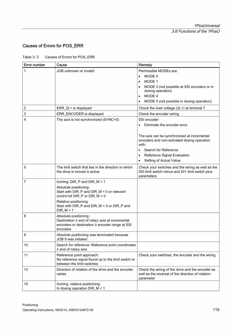
1PosUniversal 3.6 Functions of the 1PosU
Positioning Operating Instructions, 06/2010, A5E00124872-05 119
Causes of Errors for POS_ERR
Table 3- 3 Causes of Errors for POS_ERR
Error number Cause Remedy 1 JOB unknown or invalid Permissible MODEs are:
MODE 0 MODE 1 MODE 3 (not possible at SSI encoders or in
dosing operation) MODE 4 MODE 5 (not possible in dosing operation)
2 ERR_2L+ is displayed Check the load voltage (2L+) at terminal 7 3 ERR_ENCODER is displayed Check the encoder wiring 4 The axis is not synchronized (SYNC=0) SSI encoder:
Eliminate the encoder error. The axis can be synchronized at incremental encoders and non-activated dosing operation with: Search for Reference Reference Signal Evaluation Setting of Actual Value
5 The limit switch that lies in the direction in which the drive is moved is active
Check your switches and the wiring as well as the DI0 limit switch minus and DI1 limit switch plus parameters
7 Inching: DIR_P and DIR_M = 1 Absolute positioning: Start with DIR_P and DIR_M = 0 or relevant control bit DIR_P or DIR_M = 0 Relative positioning: Start with DIR_P and DIR_M = 0 or DIR_P and DIR_M = 1
8 Absolute positioning : Destination ≥ end of rotary axis at incremental encoders or destination ≥ encoder range at SSI encoders
9 Absolute positioning was terminated because JOB 9 was initiated
10 Search for reference: Reference point coordinates ≥ end of rotary axis
11 Reference point approach: No reference signal found up to the limit switch or between the limit switches
Check your switches, the encoder and the wiring
13 Direction of rotation of the drive and the encoder varies
Check the wiring of the drive and the encoder as well as the reversal of the direction of rotation parameter
15 Inching, relative positioning: In dosing operation DIR_M = 1
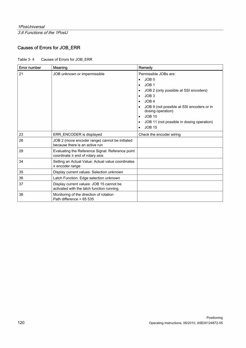
1PosUniversal 3.6 Functions of the 1PosU
Positioning 120 Operating Instructions, 06/2010, A5E00124872-05
Causes of Errors for JOB_ERR
Table 3- 4 Causes of Errors for JOB_ERR
Error number Meaning Remedy 21 JOB unknown or impermissible Permissible JOBs are:
JOB 0 JOB 1 JOB 2 (only possible at SSI encoders) JOB 3 JOB 4 JOB 9 (not possible at SSI encoders or in
dosing operation) JOB 10 JOB 11 (not possible in dosing operation) JOB 15
23 ERR_ENCODER is displayed Check the encoder wiring 26 JOB 2 (move encoder range) cannot be initiated
because there is an active run
29 Evaluating the Reference Signal: Reference point coordinate ≥ end of rotary axis
34 Setting an Actual Value: Actual value coordinates ≥ encoder range
35 Display current values: Selection unknown 36 Latch Function: Edge selection unknown 37 Display current values: JOB 15 cannot be
activated with the latch function running.
38 Monitoring of the direction of rotation Path difference > 65 535
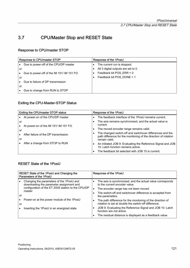
1PosUniversal 3.7 CPU/Master Stop and RESET State
Positioning Operating Instructions, 06/2010, A5E00124872-05 121
3.7 CPU/Master Stop and RESET State
Response to CPU/master STOP Response to CPU/master STOP Response of the 1PosU Due to power-off of the CPU/DP master or Due to power-off of the IM 151/ IM 151 FO or Due to failure of DP transmission or Due to change from RUN to STOP
The current run is stopped. All 3 digital outputs are set to 0. Feedback bit POS_ERR = 0 Feedback bit POS_DONE = 1
Exiting the CPU-Master-STOP Status Exiting the CPU/master STOP status Response of the 1PosU At power-on of the CPU/DP master or At power-on of the IM 151/ IM 151 FO or After failure of the DP transmission or After a change from STOP to RUN
The feedback interface of the 1PosU remains current. The axis remains synchronized, and the actual value is
current. The moved encoder range remains valid. The changed switch-off and switchover differences and the
path difference for the monitoring of the direction of rotation remain valid.
An initiated JOB 9: Evaluating the Reference Signal and JOB 10: Latch function remains active.
The feedback bit selected with JOB 15 is current.
RESET State of the 1PosU RESET State of the 1PosU and Changing the Parameters of the 1PosU
Response of the 1PosU
Changing the parameters of the 1PosU and downloading the parameter assignment and configuration of the ET 200S station to the CPU/DP master
or Power-on at the power module of the 1PosU or Inserting the 1PosU in an energized state
The axis is synchronized, and the actual value corresponds to the current encoder value.
The encoder range has not been moved. The switch-off and switchover difference is accepted from
the parameters. The path difference for the monitoring of the direction of
rotation is set at double the switch-off difference. JOB 9: Evaluating the Reference Signal and JOB 10: Latch
function are not active. The residual distance is displayed as a feedback value.
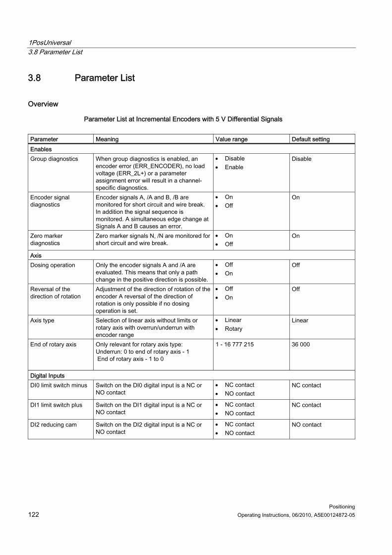
1PosUniversal 3.8 Parameter List
Positioning 122 Operating Instructions, 06/2010, A5E00124872-05
3.8 Parameter List
Overview
Parameter List at Incremental Encoders with 5 V Differential Signals Parameter Meaning Value range Default setting Enables Group diagnostics When group diagnostics is enabled, an
encoder error (ERR_ENCODER), no load voltage (ERR_2L+) or a parameter assignment error will result in a channel-specific diagnostics.
Disable Enable
Disable
Encoder signal diagnostics
Encoder signals A, /A and B, /B are monitored for short circuit and wire break. In addition the signal sequence is monitored. A simultaneous edge change at Signals A and B causes an error.
On Off
On
Zero marker diagnostics
Zero marker signals N, /N are monitored for short circuit and wire break.
On Off
On
Axis Dosing operation Only the encoder signals A and /A are
evaluated. This means that only a path change in the positive direction is possible.
Off On
Off
Reversal of the direction of rotation
Adjustment of the direction of rotation of the encoder A reversal of the direction of rotation is only possible if no dosing operation is set.
Off On
Off
Axis type Selection of linear axis without limits or rotary axis with overrun/underrun with encoder range
Linear Rotary
Linear
End of rotary axis Only relevant for rotary axis type: Underrun: 0 to end of rotary axis - 1 End of rotary axis - 1 to 0
1 - 16 777 215 36 000
Digital Inputs DI0 limit switch minus Switch on the DI0 digital input is a NC or
NO contact NC contact NO contact
NC contact
DI1 limit switch plus Switch on the DI1 digital input is a NC or NO contact
NC contact NO contact
NC contact
DI2 reducing cam Switch on the DI2 digital input is a NC or NO contact
NC contact NO contact
NO contact
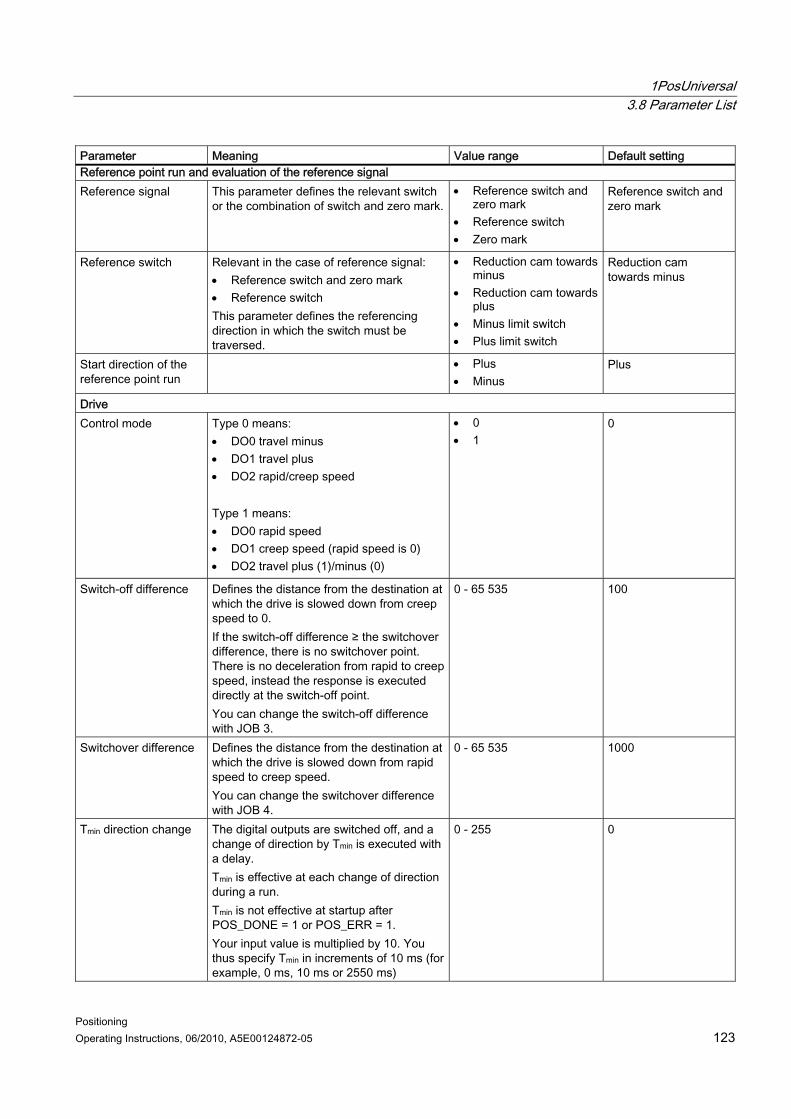
1PosUniversal 3.8 Parameter List
Positioning Operating Instructions, 06/2010, A5E00124872-05 123
Parameter Meaning Value range Default setting Reference point run and evaluation of the reference signal Reference signal This parameter defines the relevant switch
or the combination of switch and zero mark. Reference switch and
zero mark Reference switch Zero mark
Reference switch and zero mark
Reference switch Relevant in the case of reference signal: Reference switch and zero mark Reference switch This parameter defines the referencing direction in which the switch must be traversed.
Reduction cam towards minus
Reduction cam towards plus
Minus limit switch Plus limit switch
Reduction cam towards minus
Start direction of the reference point run
Plus Minus
Plus
Drive Control mode Type 0 means:
DO0 travel minus DO1 travel plus DO2 rapid/creep speed Type 1 means: DO0 rapid speed DO1 creep speed (rapid speed is 0) DO2 travel plus (1)/minus (0)
0 1
0
Switch-off difference Defines the distance from the destination at which the drive is slowed down from creep speed to 0. If the switch-off difference ≥ the switchover difference, there is no switchover point. There is no deceleration from rapid to creep speed, instead the response is executed directly at the switch-off point. You can change the switch-off difference with JOB 3.
0 - 65 535 100
Switchover difference Defines the distance from the destination at which the drive is slowed down from rapid speed to creep speed. You can change the switchover difference with JOB 4.
0 - 65 535 1000
Tmin direction change The digital outputs are switched off, and a change of direction by Tmin is executed with a delay. Tmin is effective at each change of direction during a run. Tmin is not effective at startup after POS_DONE = 1 or POS_ERR = 1. Your input value is multiplied by 10. You thus specify Tmin in increments of 10 ms (for example, 0 ms, 10 ms or 2550 ms)
0 - 255 0
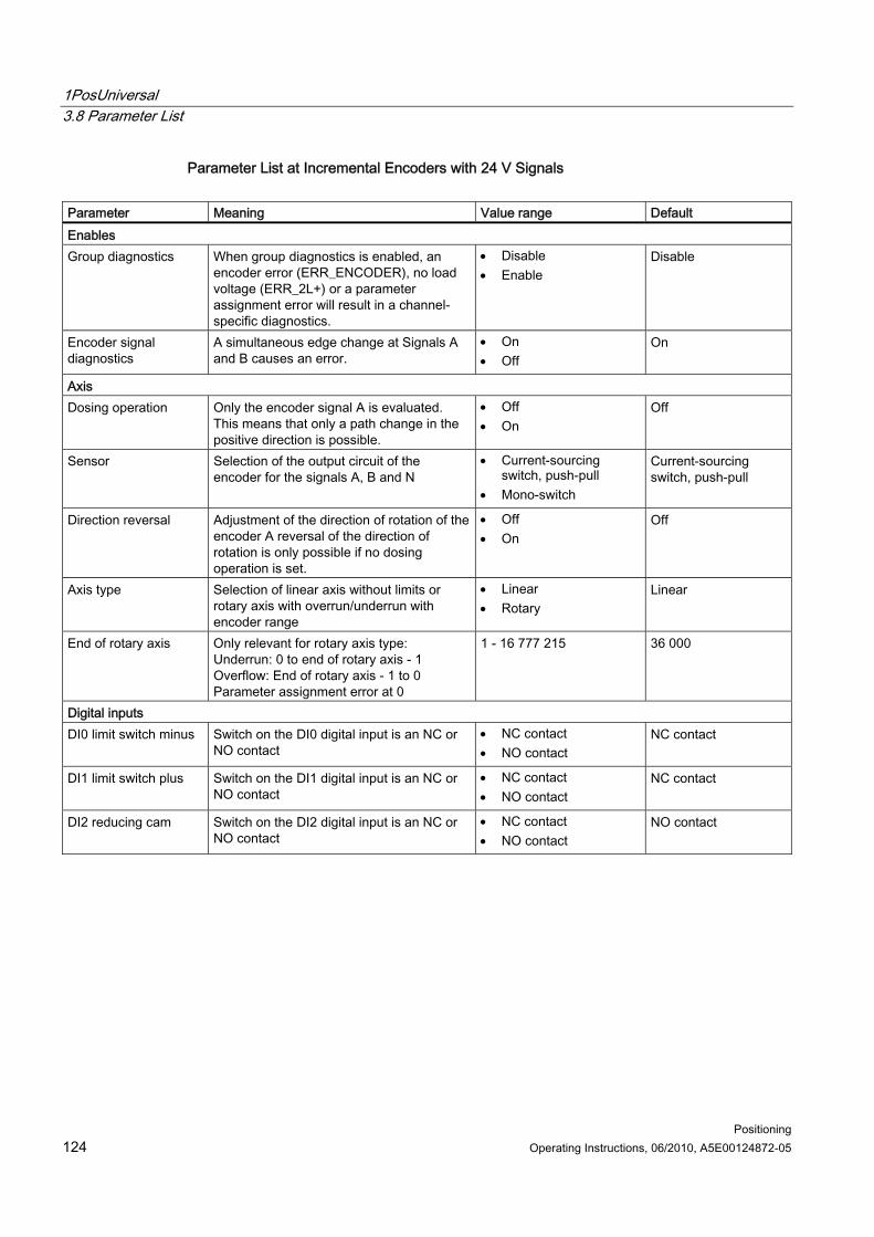
1PosUniversal 3.8 Parameter List
Positioning 124 Operating Instructions, 06/2010, A5E00124872-05
Parameter List at Incremental Encoders with 24 V Signals Parameter Meaning Value range Default Enables Group diagnostics When group diagnostics is enabled, an
encoder error (ERR_ENCODER), no load voltage (ERR_2L+) or a parameter assignment error will result in a channel-specific diagnostics.
Disable Enable
Disable
Encoder signal diagnostics
A simultaneous edge change at Signals A and B causes an error.
On Off
On
Axis Dosing operation Only the encoder signal A is evaluated.
This means that only a path change in the positive direction is possible.
Off On
Off
Sensor Selection of the output circuit of the encoder for the signals A, B and N
Current-sourcing switch, push-pull
Mono-switch
Current-sourcing switch, push-pull
Direction reversal Adjustment of the direction of rotation of the encoder A reversal of the direction of rotation is only possible if no dosing operation is set.
Off On
Off
Axis type Selection of linear axis without limits or rotary axis with overrun/underrun with encoder range
Linear Rotary
Linear
End of rotary axis Only relevant for rotary axis type: Underrun: 0 to end of rotary axis - 1 Overflow: End of rotary axis - 1 to 0 Parameter assignment error at 0
1 - 16 777 215 36 000
Digital inputs DI0 limit switch minus Switch on the DI0 digital input is an NC or
NO contact NC contact NO contact
NC contact
DI1 limit switch plus Switch on the DI1 digital input is an NC or NO contact
NC contact NO contact
NC contact
DI2 reducing cam Switch on the DI2 digital input is an NC or NO contact
NC contact NO contact
NO contact
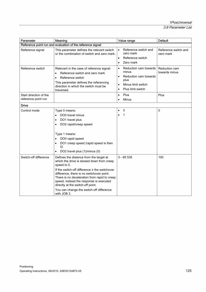
1PosUniversal 3.8 Parameter List
Positioning Operating Instructions, 06/2010, A5E00124872-05 125
Parameter Meaning Value range Default Reference point run and evaluation of the reference signal Reference signal This parameter defines the relevant switch
or the combination of switch and zero mark. Reference switch and
zero mark Reference switch Zero mark
Reference switch and zero mark
Reference switch Relevant in the case of reference signal: Reference switch and zero mark Reference switch This parameter defines the referencing direction in which the switch must be traversed.
Reduction cam towards minus
Reduction cam towards plus
Minus limit switch Plus limit switch
Reduction cam towards minus
Start direction of the reference point run
Plus Minus
Plus
Drive Control mode Type 0 means:
DO0 travel minus DO1 travel plus DO2 rapid/creep speed Type 1 means: DO0 rapid speed DO1 creep speed (rapid speed is then
0) DO2 travel plus (1)/minus (0)
0 1
0
Switch-off difference Defines the distance from the target at which the drive is slowed down from creep speed to 0. If the switch-off difference ≥ the switchover difference, there is no switchover point. There is no deceleration from rapid to creep speed, instead the response is executed directly at the switch-off point. You can change the switch-off difference with JOB 3.
0 - 65 535 100
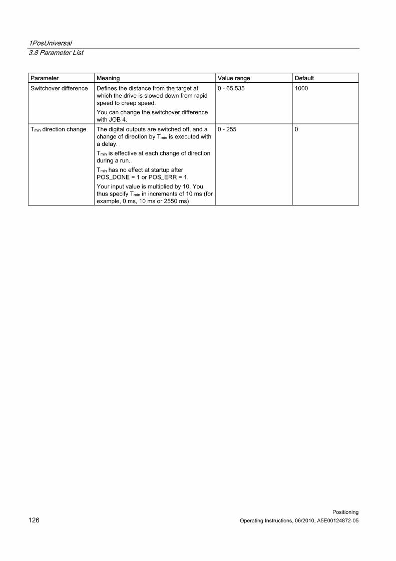
1PosUniversal 3.8 Parameter List
Positioning 126 Operating Instructions, 06/2010, A5E00124872-05
Parameter Meaning Value range Default Switchover difference Defines the distance from the target at
which the drive is slowed down from rapid speed to creep speed. You can change the switchover difference with JOB 4.
0 - 65 535 1000
Tmin direction change The digital outputs are switched off, and a change of direction by Tmin is executed with a delay. Tmin is effective at each change of direction during a run. Tmin has no effect at startup after POS_DONE = 1 or POS_ERR = 1. Your input value is multiplied by 10. You thus specify Tmin in increments of 10 ms (for example, 0 ms, 10 ms or 2550 ms)
0 - 255 0
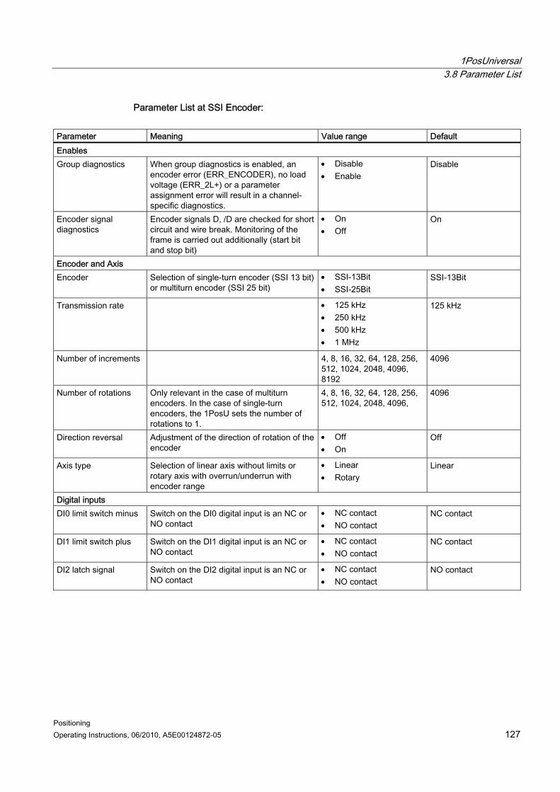
1PosUniversal 3.8 Parameter List
Positioning Operating Instructions, 06/2010, A5E00124872-05 127
Parameter List at SSI Encoder: Parameter Meaning Value range Default Enables Group diagnostics When group diagnostics is enabled, an
encoder error (ERR_ENCODER), no load voltage (ERR_2L+) or a parameter assignment error will result in a channel-specific diagnostics.
Disable Enable
Disable
Encoder signal diagnostics
Encoder signals D, /D are checked for short circuit and wire break. Monitoring of the frame is carried out additionally (start bit and stop bit)
On Off
On
Encoder and Axis Encoder Selection of single-turn encoder (SSI 13 bit)
or multiturn encoder (SSI 25 bit) SSI-13Bit SSI-25Bit
SSI-13Bit
Transmission rate 125 kHz 250 kHz 500 kHz 1 MHz
125 kHz
Number of increments 4, 8, 16, 32, 64, 128, 256, 512, 1024, 2048, 4096, 8192
4096
Number of rotations Only relevant in the case of multiturn encoders. In the case of single-turn encoders, the 1PosU sets the number of rotations to 1.
4, 8, 16, 32, 64, 128, 256, 512, 1024, 2048, 4096,
4096
Direction reversal Adjustment of the direction of rotation of the encoder
Off On
Off
Axis type Selection of linear axis without limits or rotary axis with overrun/underrun with encoder range
Linear Rotary
Linear
Digital inputs DI0 limit switch minus Switch on the DI0 digital input is an NC or
NO contact NC contact NO contact
NC contact
DI1 limit switch plus Switch on the DI1 digital input is an NC or NO contact
NC contact NO contact
NC contact
DI2 latch signal Switch on the DI2 digital input is an NC or NO contact
NC contact NO contact
NO contact
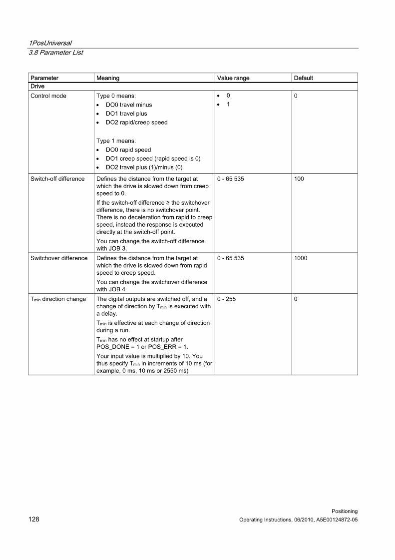
1PosUniversal 3.8 Parameter List
Positioning 128 Operating Instructions, 06/2010, A5E00124872-05
Parameter Meaning Value range Default Drive Control mode Type 0 means:
DO0 travel minus DO1 travel plus DO2 rapid/creep speed Type 1 means: DO0 rapid speed DO1 creep speed (rapid speed is 0) DO2 travel plus (1)/minus (0)
0 1
0
Switch-off difference Defines the distance from the target at which the drive is slowed down from creep speed to 0. If the switch-off difference ≥ the switchover difference, there is no switchover point. There is no deceleration from rapid to creep speed, instead the response is executed directly at the switch-off point. You can change the switch-off difference with JOB 3.
0 - 65 535 100
Switchover difference Defines the distance from the target at which the drive is slowed down from rapid speed to creep speed. You can change the switchover difference with JOB 4.
0 - 65 535 1000
Tmin direction change The digital outputs are switched off, and a change of direction by Tmin is executed with a delay. Tmin is effective at each change of direction during a run. Tmin has no effect at startup after POS_DONE = 1 or POS_ERR = 1. Your input value is multiplied by 10. You thus specify Tmin in increments of 10 ms (for example, 0 ms, 10 ms or 2550 ms)
0 - 255 0
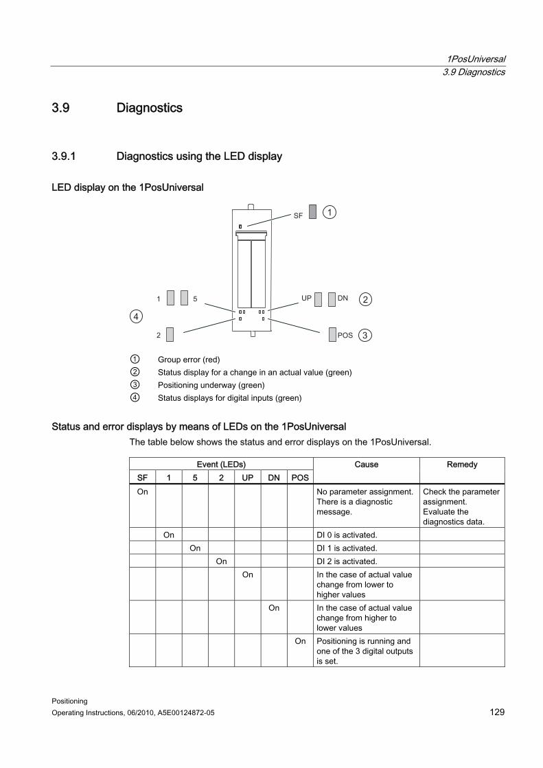
1PosUniversal 3.9 Diagnostics
Positioning Operating Instructions, 06/2010, A5E00124872-05 129
3.9 Diagnostics
3.9.1 Diagnostics using the LED display
LED display on the 1PosUniversal
1
2
3
4
① Group error (red) ② Status display for a change in an actual value (green) ③ Positioning underway (green) ④ Status displays for digital inputs (green)
Status and error displays by means of LEDs on the 1PosUniversal The table below shows the status and error displays on the 1PosUniversal.
Event (LEDs) SF 1 5 2 UP DN POS
Cause Remedy
On No parameter assignment. There is a diagnostic message.
Check the parameter assignment. Evaluate the diagnostics data.
On DI 0 is activated. On DI 1 is activated. On DI 2 is activated. On In the case of actual value
change from lower to higher values
On In the case of actual value change from higher to lower values
On Positioning is running and one of the 3 digital outputs is set.
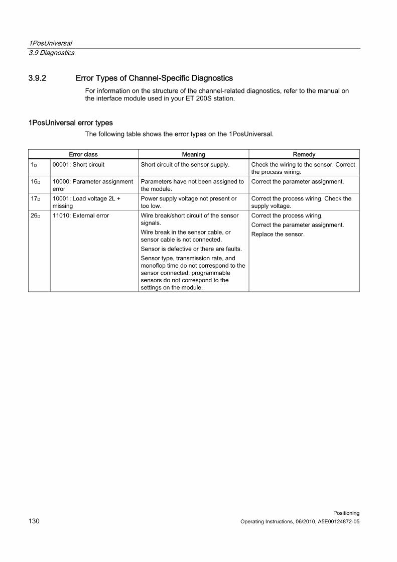
1PosUniversal 3.9 Diagnostics
Positioning 130 Operating Instructions, 06/2010, A5E00124872-05
3.9.2 Error Types of Channel-Specific Diagnostics For information on the structure of the channel-related diagnostics, refer to the manual on the interface module used in your ET 200S station.
1PosUniversal error types The following table shows the error types on the 1PosUniversal.
Error class Meaning Remedy
1D 00001: Short circuit Short circuit of the sensor supply. Check the wiring to the sensor. Correct the process wiring.
16D 10000: Parameter assignment error
Parameters have not been assigned to the module.
Correct the parameter assignment.
17D 10001: Load voltage 2L + missing
Power supply voltage not present or too low.
Correct the process wiring. Check the supply voltage.
26D 11010: External error Wire break/short circuit of the sensor signals. Wire break in the sensor cable, or sensor cable is not connected. Sensor is defective or there are faults. Sensor type, transmission rate, and monoflop time do not correspond to the sensor connected; programmable sensors do not correspond to the settings on the module.
Correct the process wiring. Correct the parameter assignment. Replace the sensor.
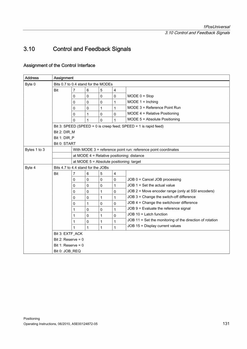
1PosUniversal 3.10 Control and Feedback Signals
Positioning Operating Instructions, 06/2010, A5E00124872-05 131
3.10 Control and Feedback Signals
Assignment of the Control Interface Address Assignment
Bits 0.7 to 0.4 stand for the MODEs 7 6 5 4 0 0 0 0 0 0 0 1 0 0 1 1 0 1 0 0
Bit
0 1 0 1
MODE 0 = Stop MODE 1 = Inching MODE 3 = Reference Point Run MODE 4 = Relative Positioning MODE 5 = Absolute Positioning
Byte 0
Bit 3: SPEED (SPEED = 0 is creep feed; SPEED = 1 is rapid feed) Bit 2: DIR_M Bit 1: DIR_P Bit 0: START With MODE 3 = reference point run: reference point coordinates at MODE 4 = Relative positioning: distance
Bytes 1 to 3
at MODE 5 = Absolute positioning: target Bits 4.7 to 4.4 stand for the JOBs
7 6 5 4 0 0 0 0 0 0 0 1 0 0 1 0 0 0 1 1 0 1 0 0 1 0 0 1 1 0 1 0 1 0 1 1
Bit
1 1 1 1
JOB 0 = Cancel JOB processing JOB 1 = Set the actual value JOB 2 = Move encoder range (only at SSI encoders) JOB 3 = Change the switch-off difference JOB 4 = Change the switchover difference JOB 9 = Evaluate the reference signal JOB 10 = Latch function JOB 11 = Set the monitoring of the direction of rotation JOB 15 = Display current values
Byte 4
Bit 3: EXTF_ACK Bit 2: Reserve = 0 Bit 1: Reserve = 0 Bit 0: JOB_REQ
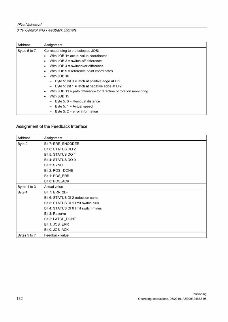
1PosUniversal 3.10 Control and Feedback Signals
Positioning 132 Operating Instructions, 06/2010, A5E00124872-05
Address Assignment Bytes 5 to 7 Corresponding to the selected JOB:
With JOB 1= actual value coordinates With JOB 3 = switch-off difference With JOB 4 = switchover difference With JOB 9 = reference point coordinates With JOB 10
– Byte 5: Bit 0 = latch at positive edge at DI2 – Byte 5: Bit 1 = latch at negative edge at DI2
With JOB 11 = path difference for direction of rotation monitoring With JOB 15
– Byte 5: 0 = Residual distance – Byte 5: 1 = Actual speed – Byte 5: 2 = error information
Assignment of the Feedback Interface Address Assignment Byte 0 Bit 7: ERR_ENCODER
Bit 6: STATUS DO 2 Bit 5: STATUS DO 1 Bit 4: STATUS DO 0 Bit 3: SYNC Bit 2: POS_ DONE Bit 1: POS_ERR Bit 0: POS_ACK
Bytes 1 to 3 Actual value Byte 4 Bit 7: ERR_2L+
Bit 6: STATUS DI 2 reduction cams Bit 5: STATUS DI 1 limit switch plus Bit 4: STATUS DI 0 limit switch minus Bit 3: Reserve Bit 2: LATCH_DONE Bit 1: JOB_ERR Bit 0: JOB_ACK
Bytes 5 to 7 Feedback value
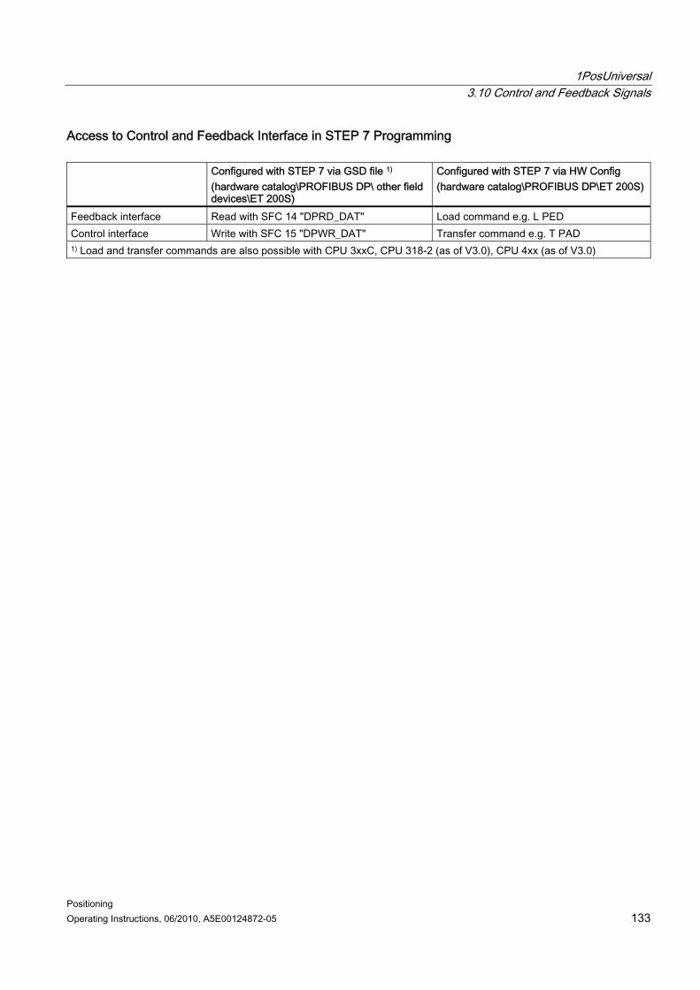
1PosUniversal 3.10 Control and Feedback Signals
Positioning Operating Instructions, 06/2010, A5E00124872-05 133
Access to Control and Feedback Interface in STEP 7 Programming Configured with STEP 7 via GSD file 1)
(hardware catalog\PROFIBUS DP\ other field devices\ET 200S)
Configured with STEP 7 via HW Config (hardware catalog\PROFIBUS DP\ET 200S)
Feedback interface Read with SFC 14 "DPRD_DAT" Load command e.g. L PED Control interface Write with SFC 15 "DPWR_DAT" Transfer command e.g. T PAD 1) Load and transfer commands are also possible with CPU 3xxC, CPU 318-2 (as of V3.0), CPU 4xx (as of V3.0)

1PosUniversal 3.11 Technical Specifications
Positioning 134 Operating Instructions, 06/2010, A5E00124872-05
3.11 Technical Specifications
Overview Technical specifications 1PosU Dimensions and weight Dimension W x H x D (mm) 30 x 81 x 52 Weight Approx. 65 g Data for specific modules Number of channels 1 Voltages, currents, potentials Rated load voltage L+ Reverse polarity protection
24 VDC Yes
Isolation Between the backplane bus and the I/O
Yes
Encoder supply Output voltage Output current
L+ -0.8 V Maximum 500 mA (total current at terminals 6 and 10), short circuit proof
Current consumption From the backplane bus From the load voltage L+ (no load)
Max. 10 mA Max. 50 mA
Power dissipation Typ. 2 W Data for the digital inputs Input voltage Rated value 0 signal 1 signal
24 VDC -30 V to 5 V 11 V to 30 V
Input current 0 signal 1 signal
≤ 2 signal (permissible leakage current) 9 mA (typically)
Minimum pulse width 500 µs Connection of a two-wire BERO Type 2 Possible Input characteristic curve To IEC 1131, Part 2, Type 2 Length of cable 50 m
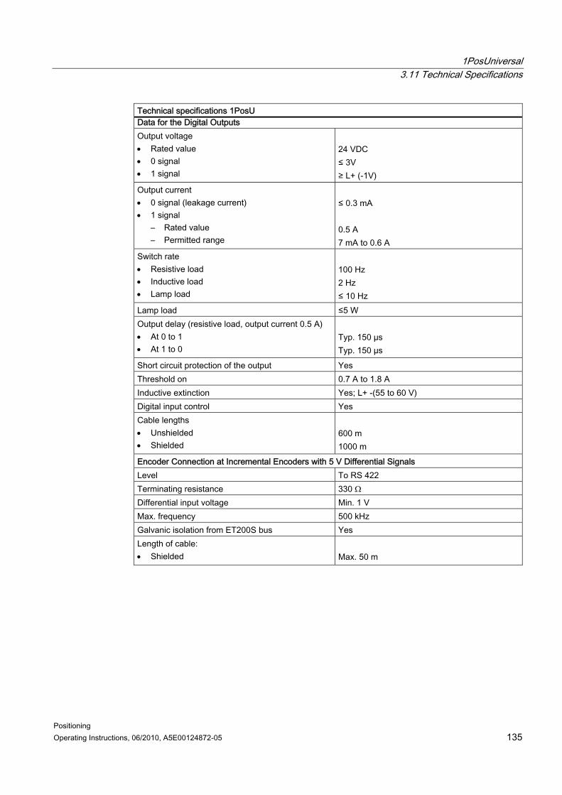
1PosUniversal 3.11 Technical Specifications
Positioning Operating Instructions, 06/2010, A5E00124872-05 135
Technical specifications 1PosU Data for the Digital Outputs Output voltage Rated value 0 signal 1 signal
24 VDC ≤ 3V ≥ L+ (-1V)
Output current 0 signal (leakage current) 1 signal
– Rated value – Permitted range
≤ 0.3 mA 0.5 A 7 mA to 0.6 A
Switch rate Resistive load Inductive load Lamp load
100 Hz 2 Hz ≤ 10 Hz
Lamp load ≤5 W Output delay (resistive load, output current 0.5 A) At 0 to 1 At 1 to 0
Typ. 150 µs Typ. 150 µs
Short circuit protection of the output Yes Threshold on 0.7 A to 1.8 A Inductive extinction Yes; L+ -(55 to 60 V) Digital input control Yes Cable lengths Unshielded Shielded
600 m 1000 m
Encoder Connection at Incremental Encoders with 5 V Differential Signals Level To RS 422 Terminating resistance 330 Ω Differential input voltage Min. 1 V Max. frequency 500 kHz Galvanic isolation from ET200S bus Yes Length of cable: Shielded
Max. 50 m
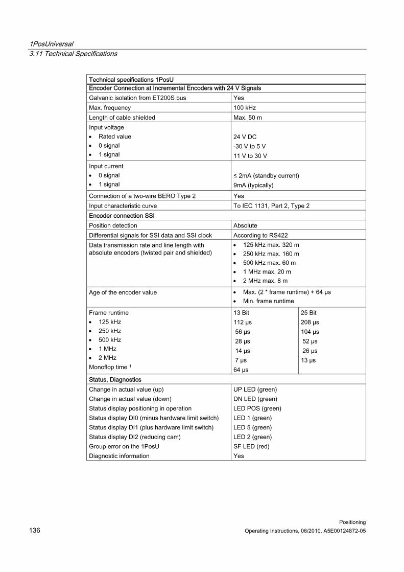
1PosUniversal 3.11 Technical Specifications
Positioning 136 Operating Instructions, 06/2010, A5E00124872-05
Technical specifications 1PosU Encoder Connection at Incremental Encoders with 24 V Signals Galvanic isolation from ET200S bus Yes Max. frequency 100 kHz Length of cable shielded Max. 50 m Input voltage Rated value 0 signal 1 signal
24 V DC -30 V to 5 V 11 V to 30 V
Input current 0 signal 1 signal
≤ 2mA (standby current) 9mA (typically)
Connection of a two-wire BERO Type 2 Yes Input characteristic curve To IEC 1131, Part 2, Type 2 Encoder connection SSI Position detection Absolute Differential signals for SSI data and SSI clock According to RS422 Data transmission rate and line length with absolute encoders (twisted pair and shielded)
125 kHz max. 320 m 250 kHz max. 160 m 500 kHz max. 60 m 1 MHz max. 20 m 2 MHz max. 8 m
Age of the encoder value Max. (2 * frame runtime) + 64 µs Min. frame runtime
Frame runtime 125 kHz 250 kHz 500 kHz 1 MHz 2 MHz Monoflop time 1
13 Bit 112 µs 56 µs 28 µs 14 µs 7 µs 64 µs
25 Bit 208 µs 104 µs 52 µs 26 µs 13 µs
Status, Diagnostics Change in actual value (up) Change in actual value (down) Status display positioning in operation Status display DI0 (minus hardware limit switch) Status display DI1 (plus hardware limit switch) Status display DI2 (reducing cam) Group error on the 1PosU Diagnostic information
UP LED (green) DN LED (green) LED POS (green) LED 1 (green) LED 5 (green) LED 2 (green) SF LED (red) Yes
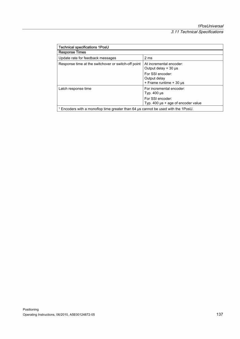
1PosUniversal 3.11 Technical Specifications
Positioning Operating Instructions, 06/2010, A5E00124872-05 137
Technical specifications 1PosU Response Times Update rate for feedback messages 2 ms Response time at the switchover or switch-off point At incremental encoder:
Output delay + 30 µs For SSI encoder: Output delay + Frame runtime + 30 µs
Latch response time For incremental encoder: Typ. 400 µs For SSI encoder: Typ. 400 µs + age of encoder value
1 Encoders with a monoflop time greater than 64 µs cannot be used with the 1PosU.

1PosUniversal 3.11 Technical Specifications
Positioning 138 Operating Instructions, 06/2010, A5E00124872-05
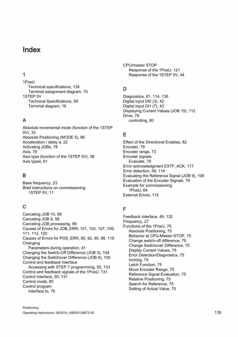
Positioning Operating Instructions, 06/2010, A5E00124872-05 139
Index
1 1PosU
Technical specifications, 134 Terminal assignment diagram, 70
1STEP 5V Technical Specifications, 59 Terminal diagram, 16
A Absolute incremental mode (function of the 1STEP 5V), 33 Absolute Positioning (MODE 5), 96 Acceleration / delay a, 22 Activating JOBs, 78 Axis, 79 Axis type (function of the 1STEP 5V), 38 Axis types, 61
B Base frequency, 23 Brief instructions on commissioning
1STEP 5V, 11
C Canceling JOB 10, 99 Canceling JOB 9, 99 Canceling JOB processing, 99 Causes of Errors for JOB_ERR, 101, 103, 107, 109, 111, 113, 120 Causes of Errors for POS_ERR, 85, 92, 95, 98, 119 Changing
Parameters during operation, 41 Changing the Switch-Off Difference (JOB 3), 104 Changing the Switchover Difference (JOB 4), 105 Control and feedback interface
Accessing with STEP 7 programming, 55, 133 Control and feedback signals of the 1PosU, 131 Control interface, 50, 131 Control mode, 80 Control program
Interface to, 76
CPU/master STOP Response of the 1PosU, 121 Response of the 1STEP 5V, 44
D Diagnostics, 61, 114, 136 Digital input DI0 (3), 42 Digital input DI1 (7), 43 Displaying Current Values (JOB 15), 112 Drive, 79
controlling, 80
E Effect of the Directional Enables, 82 Encoder, 79 Encoder range, 73 Encoder signals
Evaluate, 79 Error acknowledgment EXTF_ACK, 117 Error detection, 58, 114 Evaluating the Reference Signal (JOB 9), 106 Evaluation of the Encoder Signals, 79 Example for commissioning
1PosU, 64 External Errors, 115
F Feedback interface, 49, 132 Frequency, 27 Functions of the 1PosU, 75
Absolute Positioning, 75 Behavior at CPU-Master-STOP, 75 Change switch-off difference, 75 Change Switchover Difference, 75 Display Current Values, 75 Error Detection/Diagnostics, 75 Inching, 75 Latch Function, 75 Move Encoder Range, 75 Reference Signal Evaluation, 75 Relative Positioning, 75 Search for Reference, 75 Setting of Actual Value, 75
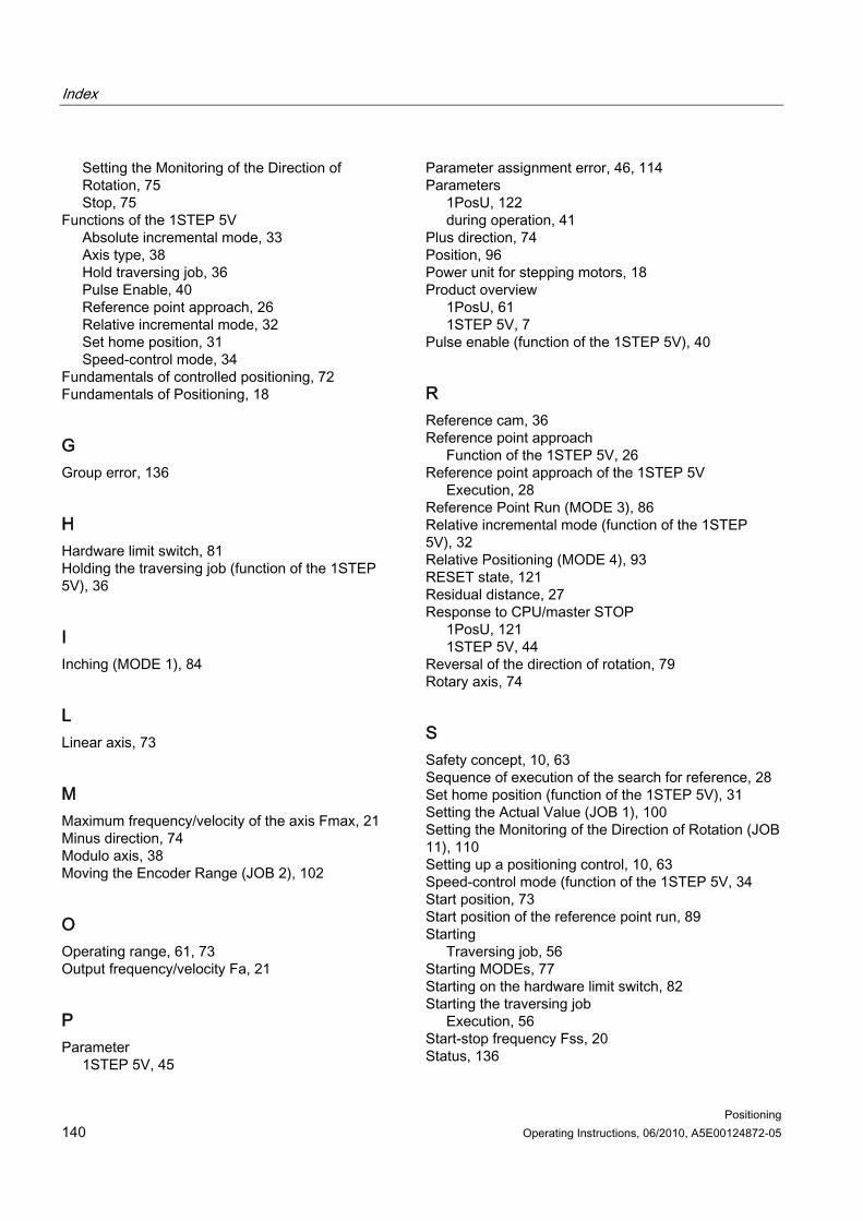
Index
Positioning 140 Operating Instructions, 06/2010, A5E00124872-05
Setting the Monitoring of the Direction of Rotation, 75 Stop, 75
Functions of the 1STEP 5V Absolute incremental mode, 33 Axis type, 38 Hold traversing job, 36 Pulse Enable, 40 Reference point approach, 26 Relative incremental mode, 32 Set home position, 31 Speed-control mode, 34
Fundamentals of controlled positioning, 72 Fundamentals of Positioning, 18
G Group error, 136
H Hardware limit switch, 81 Holding the traversing job (function of the 1STEP 5V), 36
I Inching (MODE 1), 84
L Linear axis, 73
M Maximum frequency/velocity of the axis Fmax, 21 Minus direction, 74 Modulo axis, 38 Moving the Encoder Range (JOB 2), 102
O Operating range, 61, 73 Output frequency/velocity Fa, 21
P Parameter
1STEP 5V, 45
Parameter assignment error, 46, 114 Parameters
1PosU, 122 during operation, 41
Plus direction, 74 Position, 96 Power unit for stepping motors, 18 Product overview
1PosU, 61 1STEP 5V, 7
Pulse enable (function of the 1STEP 5V), 40
R Reference cam, 36 Reference point approach
Function of the 1STEP 5V, 26 Reference point approach of the 1STEP 5V
Execution, 28 Reference Point Run (MODE 3), 86 Relative incremental mode (function of the 1STEP 5V), 32 Relative Positioning (MODE 4), 93 RESET state, 121 Residual distance, 27 Response to CPU/master STOP
1PosU, 121 1STEP 5V, 44
Reversal of the direction of rotation, 79 Rotary axis, 74
S Safety concept, 10, 63 Sequence of execution of the search for reference, 28 Set home position (function of the 1STEP 5V), 31 Setting the Actual Value (JOB 1), 100 Setting the Monitoring of the Direction of Rotation (JOB 11), 110 Setting up a positioning control, 10, 63 Speed-control mode (function of the 1STEP 5V, 34 Start position, 73 Start position of the reference point run, 89 Starting
Traversing job, 56 Starting MODEs, 77 Starting on the hardware limit switch, 82 Starting the traversing job
Execution, 56 Start-stop frequency Fss, 20 Status, 136
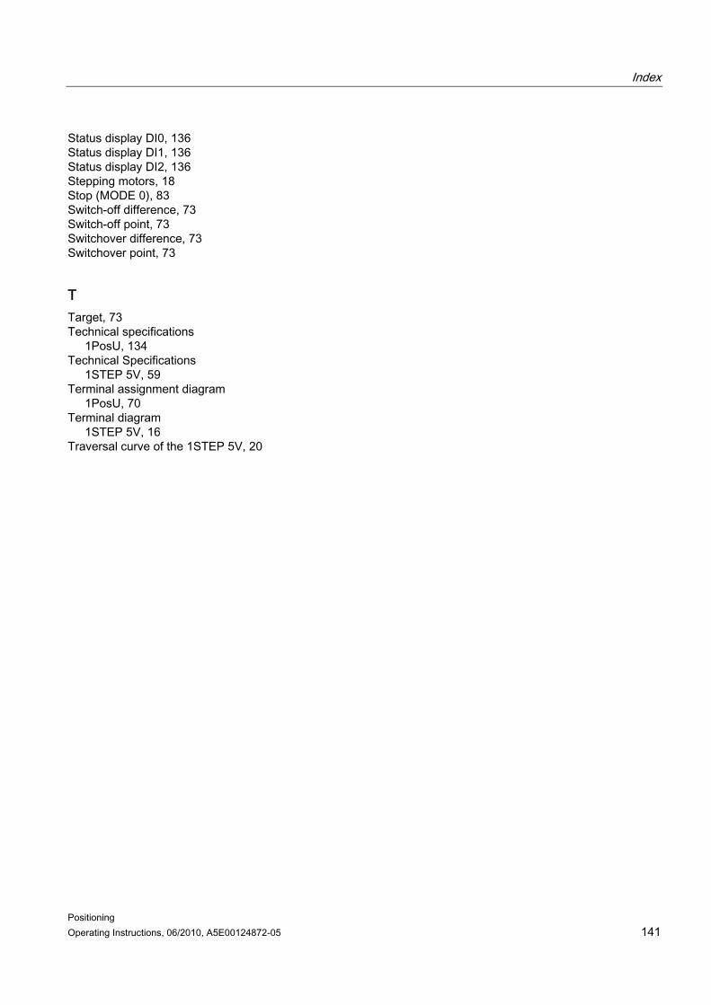
Index
Positioning Operating Instructions, 06/2010, A5E00124872-05 141
Status display DI0, 136 Status display DI1, 136 Status display DI2, 136 Stepping motors, 18 Stop (MODE 0), 83 Switch-off difference, 73 Switch-off point, 73 Switchover difference, 73 Switchover point, 73
T Target, 73 Technical specifications
1PosU, 134 Technical Specifications
1STEP 5V, 59 Terminal assignment diagram
1PosU, 70 Terminal diagram
1STEP 5V, 16 Traversal curve of the 1STEP 5V, 20

Index
Positioning 142 Operating Instructions, 06/2010, A5E00124872-05