et 438 b digital control and data acquisition department
TRANSCRIPT

4/25/2016
1
ET 438 b Digital Control and Data Acquisition
Department of Technology
1 Lesson 18_et438b.pptx
After this presentation you will be able to:
Identify the key parts of a programmable logic controller (PLC)
Explain how a PLC functions in the run mode
Identify various types of input/output modules used with PLC processors
Identify file structure type for a typical PLC family of processors.
2 Lesson 18_et438b.pptx

4/25/2016
2
Lesson 18_et438b.pptx 3
Microprocessor-based controller that implements ladder logic through software and hardware interface.
Definition of PLC Digital apparatus using programmable memory and stored programs for implementing Logic Timing Sequencing Counting
Field devices (sensors)
INPUT MODULES
CPU
Field devices
(control values, solenoids)
OUTPUT MODULE
Memory Programmer USER
Basic Block Diagram of A PLC
Lesson 18_et438b.pptx 4
1. Scan all Inputs Detect change in status of field devices (Limit switches Pressure switches, etc.)
Time from 1 to 4 called scan time. Can be important in programs
2. Execute control program based on user logic design
3. Test output status against program values.
4. Update output to fit changes dictated by input change

4/25/2016
3
Lesson 18_et438b.pptx 5
Solid state sensors (electronic) proximity switches, photo eyes etc.
Voltage levels 24 - 240 Vac 24-240 Vdc TTL levels, Sourcing and sinking I/O
PLC I/O designed to connect to industrial devices
Dry contacts (standard switches) motor contactors Pressure, temperature, limit, flow switches
I/O grouped on cards with 8, 16, 24,32 inputs
1 set terminals (com, n) = 1 I/O point
Lesson 18_et438b.pptx 6
PLC’s use memory mapped I/O
PLC uses microprocessors with 8-16 bit words. Each I/O point identified by location in memory. Terminals have unique addresses represented by decimal, octal or binary number. (commonly decimal)
Each memory word maps to group of
I/O points
Bits represent status of I/O field devices
1=on, 0=off

4/25/2016
4
Lesson 18_et438b.pptx 7
Non-expandable PLCs use fixed addressing: All slot 0
For expandable PLCs
Level 1: Rack or chassis identifier
Level 2: Slot identifier (type
of I/O card)
Level 3: I/O point. Type of point and terminal number
I/O Status Table
Word 1
Word 2
Word 3
Word 4
Word 5
Word 6
1 0 0 00 0 1 1 0 0 1 01 0 1 0
Lesson 18_et438b.pptx 8
Addressing of I/O cards (Allen-Bradley (A-B))
X:n
A-B uses decimal expandable addressing for most PLCs
Slot Number
Function I/O
X:n/p
Addressing Specific I/O points (Allen-Bradley)
Function I/O
Slot Number
Terminal Number
For fixed PLC designs, all I/O addressed to slot 0

4/25/2016
5
Lesson 18_et438b.pptx 9
I/O Addressing Examples
Function Chassis Slot Terminal # Address input 1 4 I:1/4 output 2 13 O:2/13 input 3 2 I:3/2 input 4 4 I:4/4
Note: Decimal addressing used above
Other PLC data types: Bit data, unsigned integer, signed integer, BCD (binary coded decimal 0-9 binary)
Lesson 18_et438b.pptx 10
Sequential control uses discrete (binary) inputs (on/off) from field devices (switches sensors, etc.)
Typical Type of Input Modules
Ac Dc 24, 48, 120, 240 V 24, 48, 1-60 120 Vdc 120, 240 V isolated sink/source 5-50 Vdc 24 Vac/dc 5 V TTL 5/12 V TTL
Input module considered load of field device (switch)
common source
field devices
4/25/2016
6
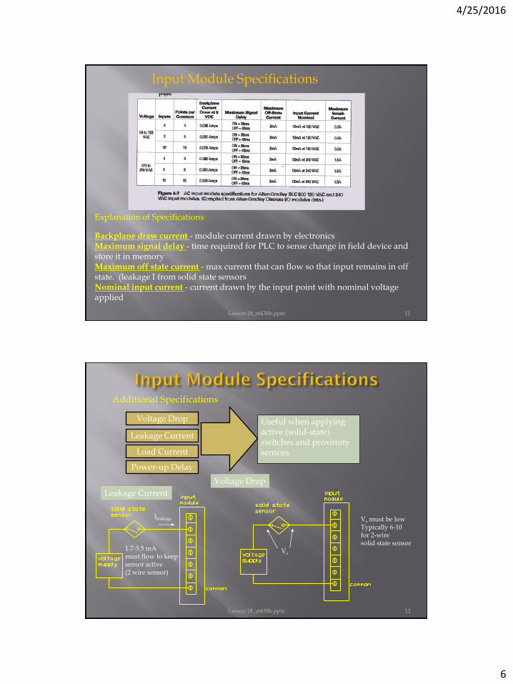
Lesson 18_et438b.pptx 11
Input Module Specifications
Explanation of Specifications
Backplane draw current - module current drawn by electronics Maximum signal delay - time required for PLC to sense change in field device and store it in memory Maximum off state current - max current that can flow so that input remains in off state. (leakage I from solid state sensors Nominal input current - current drawn by the input point with nominal voltage applied
Lesson 18_et438b.pptx 12
Additional Specifications
Useful when applying active (solid-state) switches and proximity sensors
Voltage Drop
Leakage Current
Load Current
Power-up Delay
Ileakage
1.7-3.5 mA must flow to keep sensor active (2 wire sensor)
Leakage Current
Voltage Drop
Vs
Vs must be low Typically 6-10 for 2-wire solid state sensor

4/25/2016
7
Lesson 18_et438b.pptx 13
When solid-state 2-wire sensor is used with switch, sensor will be inactive until circuit is completed
Power-up Delay
Open Ckt
Dealing with power up delay - add parallel resistor. Must allow enough current to activate sensor but not turn on input module
Lesson 18_et438b.pptx 14
Dealing with power up delay - add parallel resistor.
Example: size R Vs = 115 Vac IL = 1.7 mA
R = 115 V/ 1.7 mA R = 67.647 kW

4/25/2016
8
Lesson 18_et438b.pptx 15
Minimum load current-lowest I value that keeps the sensor active May need to parallel a resistor with the input card if it has a high impedance input or sensor needs more current than card can handle without turning on the input
R
R called bleeder resistor. Usually sized according to manufacturer charts
Based on concept of current division
Dc input modules can either be sources or sinks for dc current. This
depends on the transistor used in the input card and the polarity of the dc
supply
NPN sinks
current
to ground
Sinking
Sourcing Equivalent
circuit
transistor
sources
current to
load
Switch sinks load
current
Switch sources
load current
PNP
16 Lesson 18_et438b.pptx
4/25/2016
9
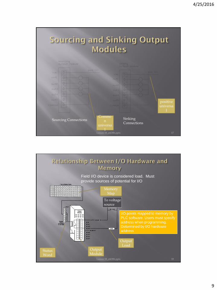
Sourcing Connections Sinking Connections
Common
universal
positive universa
l
17 Lesson 18_et438b.pptx
Field I/O device is considered load. Must
provide sources of potential for I/O
Output Load
Output Module
To voltage source
I/O points mapped to memory by
PLC software. Users must specify
address when programming.
Determined by I/O hardware
address
Memory Map
Status Word
18 Lesson 18_et438b.pptx
4/25/2016
10
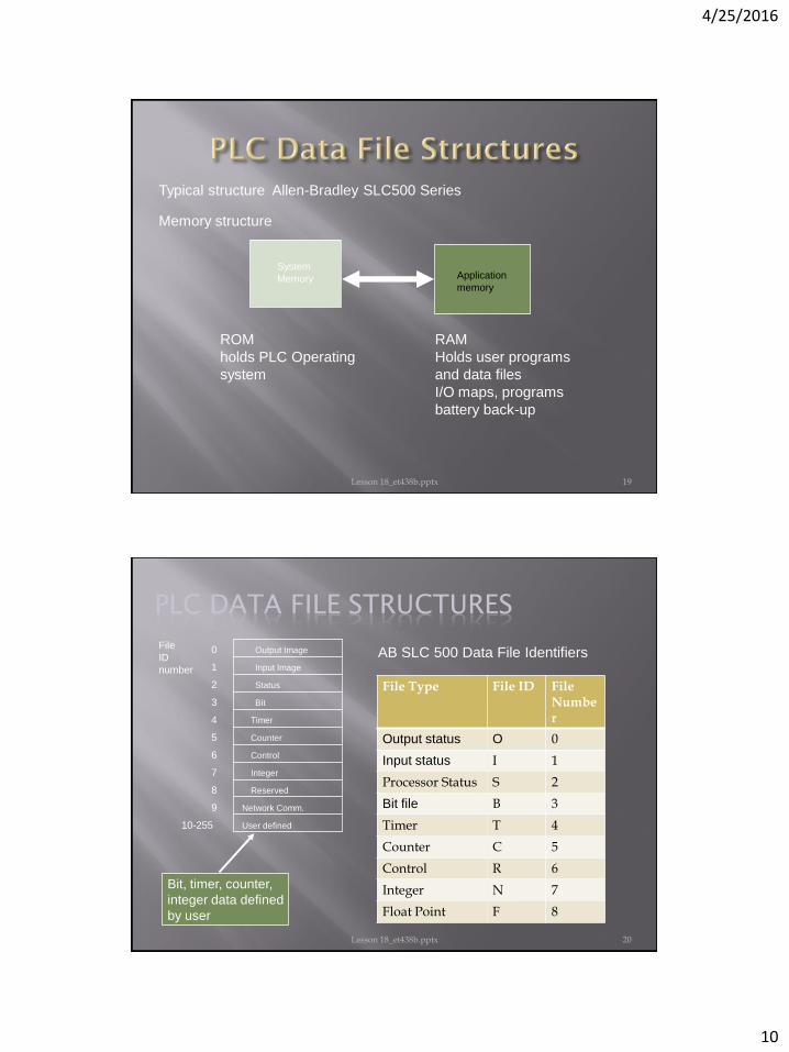
Typical structure Allen-Bradley SLC500 Series
Memory structure
System
Memory Application
memory
ROM
holds PLC Operating
system
RAM
Holds user programs
and data files
I/O maps, programs
battery back-up
19 Lesson 18_et438b.pptx
PLC DATA FILE STRUCTURES
Bit, timer, counter,
integer data defined
by user
0
1
2
3
4
5
6
7
8
9
10-255
Output Image
Input Image
Status
Bit
Timer
Counter
Control
Integer
Reserved
Network Comm.
User defined
File
ID
number
AB SLC 500 Data File Identifiers
File Type File ID File Number
Output status O 0
Input status I 1
Processor Status S 2
Bit file B 3
Timer T 4
Counter C 5
Control R 6
Integer N 7
Float Point F 8
20 Lesson 18_et438b.pptx

4/25/2016
11
PLC DATA FILE STRUCTURES
addr. 15 14 13 12 0 1 2 11 10 9 8 7 6 5 4 3
Address depends on slot location of the Output card
and number of points
File 0 - Output image single memory words
O:1
O:2
O:5
0 0 1 0 1 0 1 0
Slot address
Point Map
Unused
21 Lesson 18_et438b.pptx
OUTPUT IMAGE FILE
addr. 15 14 13 12 0 1 2 11 10 9 8 7 6 5 4 3
O:2
O:5
O:6
O:7
PLC has an 16 output card in slot 2
An 8 output card in slot 5
A 16 output card in slot 6
An 8 output card in slot 7
x
x
x
x
Invalid
Invalid
Each card assigned a word, unused bits are not addressable
22 Lesson 18_et438b.pptx
4/25/2016
12
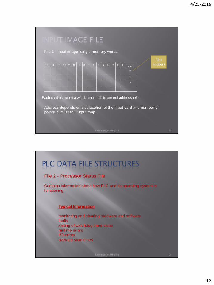
INPUT IMAGE FILE
addr. 15 14 13 12 0 1 2 11 10 9 8 7 6 5 4 3
File 1 - Input image single memory words
I:0
I:3
I:4
Slot address
Each card assigned a word, unused bits are not addressable
Address depends on slot location of the input card and number of
points. Similar to Output map.
23 Lesson 18_et438b.pptx
File 2 - Processor Status File
Contains information about how PLC and its operating system is
functioning
PLC DATA FILE STRUCTURES
Typical Information
monitoring and clearing hardware and software
faults
setting of watchdog timer value
runtime errors
I/O errors
average scan times
24 Lesson 18_et438b.pptx

4/25/2016
13
File 3 - The Bit File Bit files used to represent control relays that were
used in electromechanical systems.
Addressing bit data type
B3:n/b Bit
identifier
Word identifier
Data Type (Bit)
File ID Number
Example: For the following memory map
Determine the bit value associated with the addresses
Addresses Bit value
B3:0/5 B3:1/7 B3:2/12 B3:3/3
1 1 0 0
5 7 12 3
25 Lesson 18_et438b.pptx
addr. 15 14 13 12 0 1 2 11 10 9 8 7 6 5 4 3
B3:0
B3:1
B3:2
B3:3
1
0
Identifying individual bits
B3:2/8 B3:1/9
26 Lesson 18_et438b.pptx

4/25/2016
14
File 4 - Timers. Each timer requires 3 words of data file
Word 0 - control word I/O bits and Internal control
Word 1 - preset value
Word 2 - accumulated value
15 14 13 0
0
1
2
EN TT DN INTERNAL USE ONLY
Preset Value (PRE)
Accumulated Value (ACC)
Timer file structure and addressing
Addressable Bits
EN - timer enabled bit
TT - timer timing bit
DN - timer done bit
Data Structure is the same for on-delay and off-delay timers
27 Lesson 18_et438b.pptx
15 14 13 0
0
1
2
EN TT DN INTERNAL USE ONLY
Preset Value (PRE)
Accumulated Value (ACC)
Tf:e.s/b General form
Bit
Sub-element
Sub-elements
Element (Timer #)
Timer file # Default 4
T4:0/15 = T4:0/EN
Examples
Timer 0;
Timer enabled bit
T20:2.PRE preset of a timer defined in a user
defined file area
T4:1.ACC or T4:1.2
Accumulated value of
timer 1
T4:5/DN
Timer 5 done bit
T4:5.ACC/1
Bit one of accumulated
value of Timer 5
More Examples
T4:2/TT
Timer timing
bit: Timer 2
28 Lesson 18_et438b.pptx

4/25/2016
15
File 5 - Counters
Each counter defined by three words in data file
15 14 13 0
0
1
2
CU CD DN INTERNAL USE ONLY
Preset Value (PRE)
Accumulated Value (ACC)
OV UN UA
Word 0 - control word I/O bits and Internal control
Word 1 - preset value
Word 2 - accumulated value
Addressable Bits
CU - counter up enabled bit
CD - counter down enabled
bit
DN - counter done bit
OV - counter overflow bit
UN - counter underflow bit
UA - update accumulated
value (only certain models)
PRE - preset value
ACC -accumulated value
29 Lesson 18_et438b.pptx
COUNTER FILE STRUCTURE
15 14 13 0
0
1
2
CU CD DN INTERNAL USE ONLY
Preset Value (PRE)
Accumulated Value (ACC)
OV UN UA
Cf:e.s/b General form
Bit
Sub-element
Element (Counter
#)
Counter file # Default 5
Examples
C5:0/15 = C5:0/CU
Counter 0
count up bit
Preset of a counter defined in a user
defined file area
C5:1.ACC or C5:1.2
Accumulated value of
counter
C5:5/DN
Counter 5 done bit
C5:5.ACC/1
Bit 1 of accumulated
value of counter 5
C5:2/CD
Count down enable bit
for counter 2
C20:2.PRE
More Examples
30 Lesson 18_et438b.pptx

4/25/2016
16
File 6 -Control File
Used to store status information for bit operations and stack control
operations
File 7 – Integer Data
Integer Data types Signed integer (16 bit): range 0 -+-
32767 Unsigned integer (16 bit) range 0 -
65535
Addressing Integer values Each integer requires 1 word N7:n
Integer data Type
File ID Number
Word identifier
31 Lesson 18_et438b.pptx
ET 438B Sequential Control and Data Acquisition
Department of Technology
Lesson 18_et438b.pptx 32