etcs demo locomotive - siemens7f15bfdb-d… · etcs demo locomotive with the help of the etcs demo...
TRANSCRIPT
siemens.de/mobility
ETCS Demo LocomotiveEuropean Train Control System Demonstration Locomotive
To equip complete fleets and different vehicle classes with ETCS, an intelligent concept and well- prepared collaboration with partner companies are required.
Trainguard®As one of the ETCS pioneers, Siemens provides sophisticated, field-proven products for individual retrofit solutions and a scalable system of trackside, on-board and communi-cation equipment for all ETCS applications, called Trainguard®.
ETCS Demo LocomotiveWith the help of the ETCS demo locomotive, it is now possible to effectively visualize complex integration conditions.
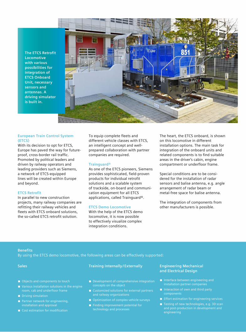
The heart, the ETCS onboard, is shown on this locomotive in different installation options. The main task for integration of the onboard units and related components is to find suitable areas in the driver’s cabin, engine compartment or underfloor frame.
Special conditions are to be consi-dered for the installation of radar sensors and balise antenna, e.g. angle arrangement of radar beam or metal-free space for balise antenna.
The integration of components from other manufacturers is possible.
The ETCS Retrofit Locomotive with various possibilities for integration of ETCS Onboard Unit, necessary sensors and antennas. A driving simulator is built in.
BenefitsBy using the ETCS demo locomotive, the following areas can be effectively supported:
Sales
■ Objects and components to touch ■ Various installation solutions in the engine room, cab and underfloor frame
■ Driving simulation ■ Partner network for engineering, installation and approval
■ Cost estimation for modification
Training Internally / Externally
■ Development of comprehensive integration concepts on the object
■ Customized solutions for external partners and railway organizations
■ Optimization of complex vehicle surveys ■ Finding improvement potential for technology and processes
Engineering Mechanical and Electrical Design
■ Interface between engineering and installation partner companies
■ Interaction of own and third party components
■ Effort estimation for engineering services ■ Testing of new technologies, e.g. 3D scan and post-production in development and engineering
European Train Control System (ETCS)With its decision to opt for ETCS, Europe has paved the way for future-proof, cross-border rail traffic. Promoted by political leaders and driven by railway operators and leading providers such as Siemens, a network of ETCS-equipped lines will be created within Europe and beyond.
ETCS RetrofitIn parallel to new construction projects, many railway companies are refitting their railway vehicles and fleets with ETCS onboard solutions, the so-called ETCS retrofit solution.
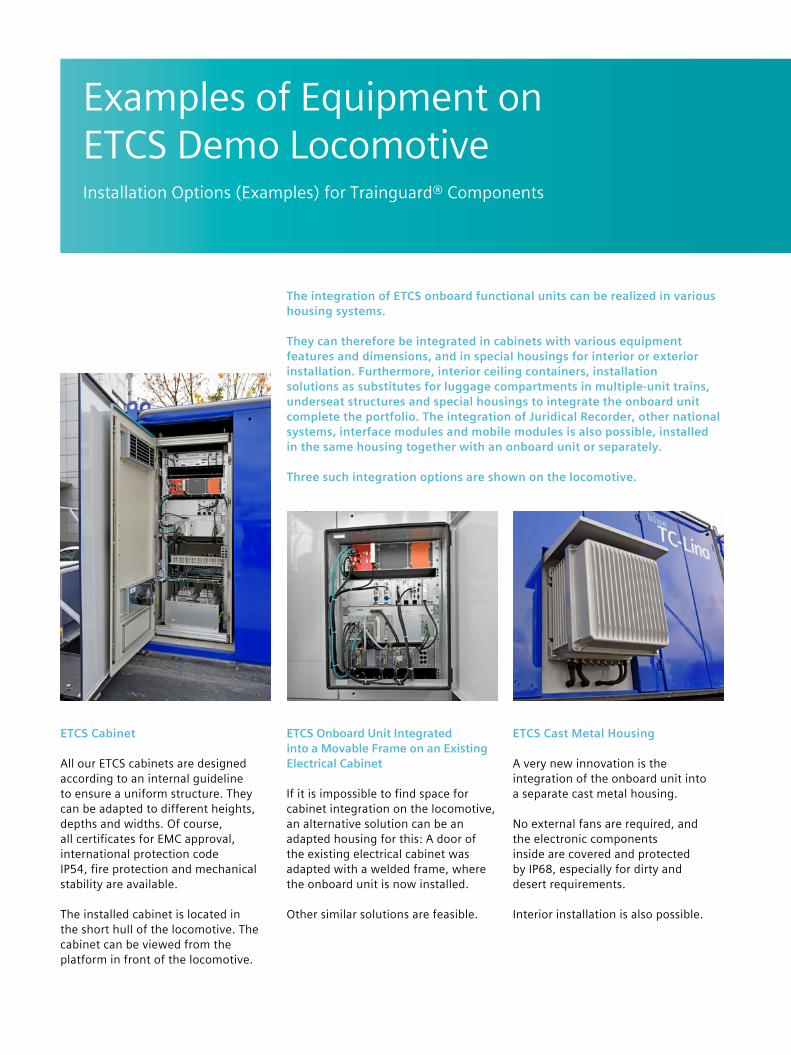
The integration of ETCS onboard functional units can be realized in various housing systems.
They can therefore be integrated in cabinets with various equipment features and dimensions, and in special housings for interior or exterior installation. Furthermore, interior ceiling containers, installation solutions as substitutes for luggage compartments in multiple-unit trains, underseat structures and special housings to integrate the onboard unit complete the portfolio. The integration of Juridical Recorder, other national systems, interface modules and mobile modules is also possible, installed in the same housing together with an onboard unit or separately.
Three such integration options are shown on the locomotive.
Examples of Equipment on ETCS Demo LocomotiveInstallation Options (Examples) for Trainguard® Components
ETCS Cabinet
All our ETCS cabinets are designed according to an internal guideline to ensure a uniform structure. They can be adapted to different heights, depths and widths. Of course, all certificates for EMC approval, international protection code IP54, fire protection and mechanical stability are available.
The installed cabinet is located in the short hull of the locomotive. The cabinet can be viewed from the platform in front of the locomotive.
ETCS Onboard Unit Integrated into a Movable Frame on an Existing Electrical Cabinet
If it is impossible to find space for cabinet integration on the locomotive, an alternative solution can be an adapted housing for this: A door of the existing electrical cabinet was adapted with a welded frame, where the onboard unit is now installed.
Other similar solutions are feasible.
ETCS Cast Metal Housing
A very new innovation is the integration of the onboard unit into a separate cast metal housing.
No external fans are required, and the electronic components inside are covered and protected by IP68, especially for dirty and desert requirements.
Interior installation is also possible.
1 2 3 4 5 6 7 8 9 10 11
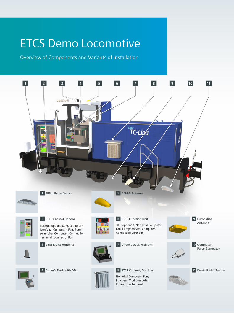
ETCS Demo LocomotiveOverview of Components and Variants of Installation
2 ETCS Cabinet, Indoor
ELBE5K (optional), JRU (optional), Non Vital Computer, Fan, Euro-pean Vital Computer, Connection Terminal, Connector Box
1 SRRIII Radar Sensor
3 GSM-R/GPS-Antenna
4 Driver’s Desk with DMI
5 GSM-R Antenna
7 Driver’s Desk with DMI
9 Eurobalise Antenna
10 Odometer Pulse Generator
6 ETCS Function Unit
JRU (optional), Non Vital Computer, Fan, European Vital Computer, Connection Cartridge
8 ETCS Cabinet, Outdoor
Non Vital Computer, Fan, European Vital Computer, Connection Terminal
11 Deuta Radar Sensor
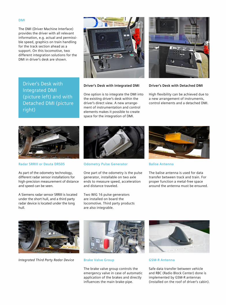
Odometry Pulse Generator
One part of the odometry is the pulse generator, installable on two axle ends to measure speed, acceleration and distance traveled.
Two WIG 16 pulse generators are installed on board the locomotive. Third party products are also integrable.
DMI
The DMI (Driver Machine Interface) provides the driver with all relevant information, e.g. actual and permissi-ble speed, graphics on train handling for the track section ahead as a support. On this locomotive, two different integration solutions for the DMI in driver’s desk are shown.
Radar SRRIII or Deuta DRS05
As part of the odometry technology, different radar sensor installations for high-precision measurement of distance and speed can be seen.
A Siemens radar sensor SRRIII is located under the short hull, and a third party radar device is located under the long hull.
Driver’s Desk with Integrated DMI (picture left) and with Detached DMI (picture right)
Driver’s Desk with Integrated DMI
One option is to integrate the DMI into the existing driver’s desk within the driver’s direct view. A new arrange-ment of instrumentation and control elements makes it possible to create space for the integration of DMI.
Driver’s Desk with Detached DMI
High flexibility can be achieved due to a new arrangement of instruments, control elements and a detached DMI.
Integrated Third Party Radar Device
Balise Antenna
The balise antenna is used for data transfer between track and train. For proper function a metal-free space around the antenna must be ensured.
GSM-R Antenna
Safe data transfer between vehicle and RBC (Radio Block Center) done is implemented by GSM-R antennas (installed on the roof of driver’s cabin).
Brake Valve Group
The brake valve group controls the emergency valve in case of automatic application of the brakes and directly influences the main brake-pipe.

Siemens AG
Mobility Management 12435 Berlin Germany
© Siemens AG 2017
The information in this document contains general descriptions of technical possibilities, which may not always be provided. The desired features therefore need to be determined individually by contractual agreement.