eti 07 performancetest - university ... - university of...
TRANSCRIPT
Engine Testing and Instrumentation 1
Performance TestPerformance Test
Engine Testing and Instrumentation 2
MAXIMUM POWER PERFORMANCE TEST
Always complete a rough hand drafted graph of the results
Is the fuel delivery a straight line ?
Do the SFC and Torque mirror each other
Build up your own memory joggers
Engine Testing and Instrumentation 3
PERFORMANCE TESTING
Build up your own memory joggers
Treat test result with caution
Are these results are believable
Not possible re-test
Engine Testing and Instrumentation 4
Repeatability of tests
• In order to be able to repeat test results, in addition to knowing the build of the engine, it is necessary to correct the results back to a standard induction temperature and barometric pressure within the test cell
• There are various standards for N/A and turbo, diesel and gasoline applications
Engine Testing and Instrumentation 5
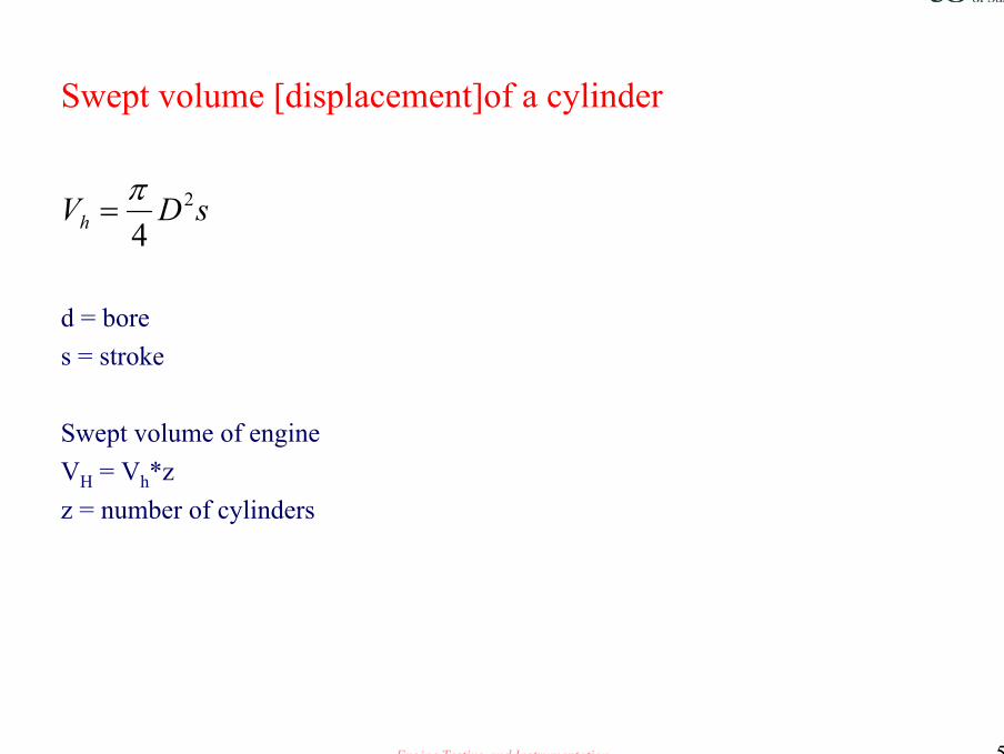
Swept volume [displacement]of a cylinder
d = bore s = stroke
Swept volume of engine VH = Vh*zz = number of cylinders
ñ
sDVh2
4π
=
Engine Testing and Instrumentation 6
Gasoline applications ~ Ignition timing
Determination of ignition timing at differing speed and load conditionsThe test is conducted throughout a wide range of ignition advance positions in
order to determine engine performance levels with differing load conditions
The test is conducted throughout a wide range of ignition advance positions in order to determine engine performance levels with full load advance
Fuel is set to L B T /M B T at the required test speed
Engine Testing and Instrumentation 7
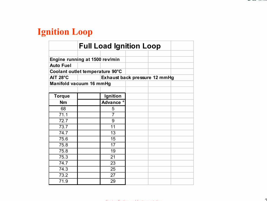
Ignition LoopFull Load Ignition Loop
Engine running at 1500 rev/minAuto FuelCoolant outlet temperature 90°CAIT 28°C Exhaust back pressure 12 mmHgManifold vacuum 16 mmHg
Torque IgnitionNm Advance °68 571.1 772.7 973.7 1174.7 1375.6 1575.8 1775.8 1975.3 2174.7 2374.3 2573.2 2771.9 29
Engine Testing and Instrumentation 8
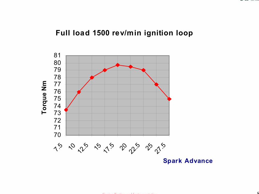
Full load 1500 rev/min ignition loop
707172737475767778798081
7.5 10 12.5 15 17.5 20 22.5 25 27.5
Spark Advance
Torq
ue N
m

Engine Testing and Instrumentation 9
Fuel Loop
Part Load Fuel Loop ReadingsEngine running at 3755 rev/min Producing 70.8 BMEP psi
Manifold Fuel flow SFCvacuum kg/hour kg/kW.hourmmHg
284 9.41 0.385285 9.18 0.375287 8.83 0.361286 8.61 0.352292 8.33 0.341290 8.1 0.331289 7.86 0.321287 7.46 0.305285 7.28 0.298265 7.02 0.287246 6.97 0.285235 6.89 0.282207 7.05 0.288190 7.15 0.292180 7.12 0.293162 7.29 0.298

Engine Testing and Instrumentation 10
Full load ignition loop 1500 rev/min
0.29
0.3
0.31
0.32
0.33
0.34
0.35
5.5
7.5 10
12.5 15
17.5 20
22.5 25
27.5 30 Spark advance
Fuel
SFC
Kg/
kw-h
our
Engine Testing and Instrumentation 11
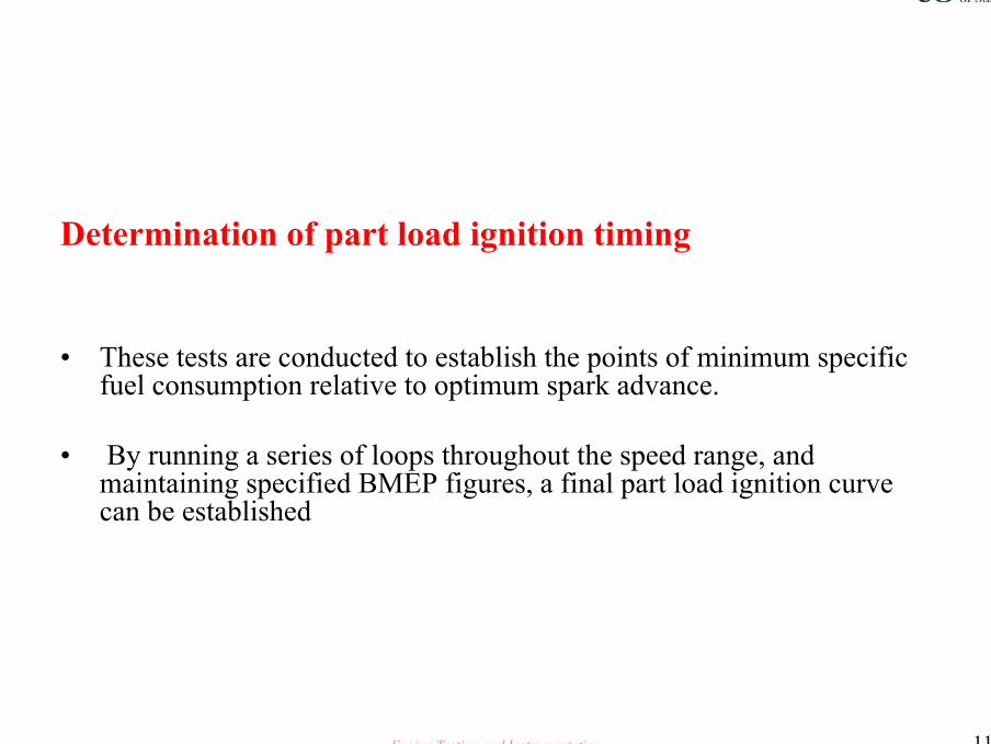
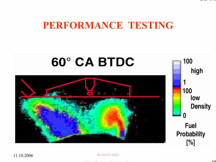
Determination of part load ignition timing
• These tests are conducted to establish the points of minimum specific fuel consumption relative to optimum spark advance.
• By running a series of loops throughout the speed range, and maintaining specified BMEP figures, a final part load ignition curve can be established
Engine Testing and Instrumentation 12
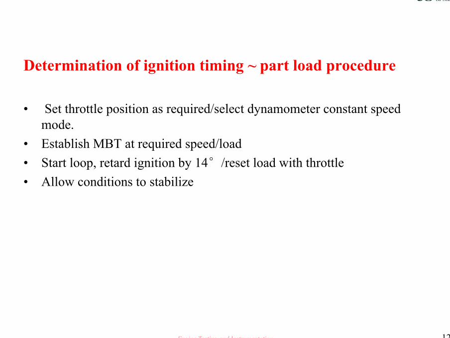
Determination of ignition timing ~ part load procedure
• Set throttle position as required/select dynamometer constant speed mode.
• Establish MBT at required speed/load• Start loop, retard ignition by 14°/reset load with throttle• Allow conditions to stabilize
Engine Testing and Instrumentation 13

Engine Testing and Instrumentation 14
Fuel loops constantthrottle setting
SFC
Fuel
1000 rev per min
1500 2000
2500
35003000
4000
Note: The minimum fuel/maximum torque pointat each fixed speed, givesa near straight line curvefor any given throttle setting
Fixed speedpoints
Manifold vacuum
Engine Testing and Instrumentation 15
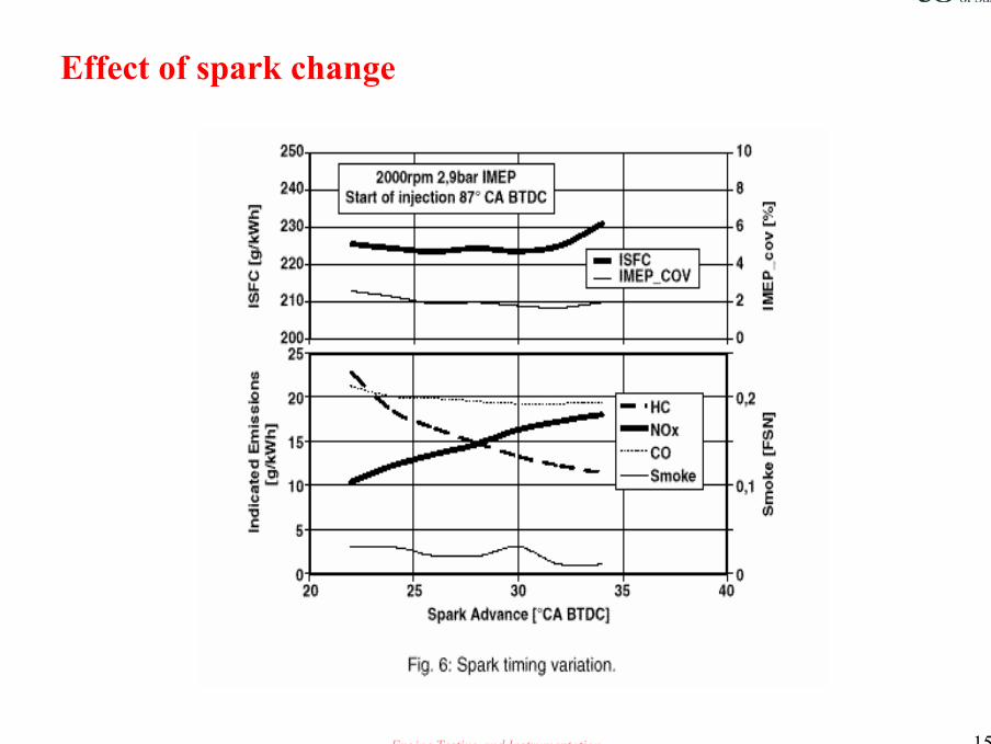
Effect of spark change
Engine Testing and Instrumentation 16
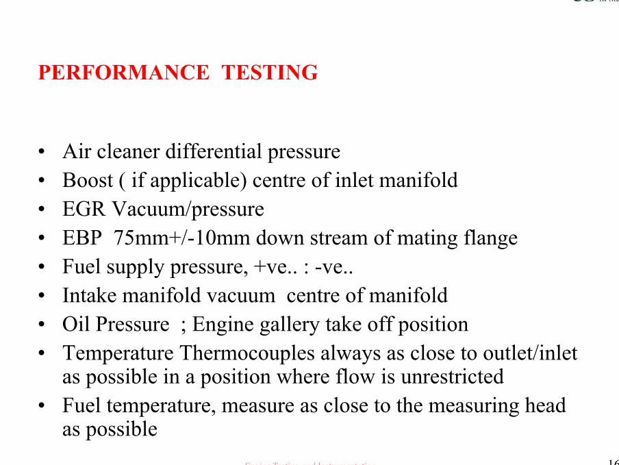
PERFORMANCE TESTING
• Air cleaner differential pressure• Boost ( if applicable) centre of inlet manifold• EGR Vacuum/pressure• EBP 75mm+/-10mm down stream of mating flange• Fuel supply pressure, +ve.. : -ve..• Intake manifold vacuum centre of manifold• Oil Pressure ; Engine gallery take off position• Temperature Thermocouples always as close to outlet/inlet
as possible in a position where flow is unrestricted• Fuel temperature, measure as close to the measuring head
as possible
Engine Testing and Instrumentation 17
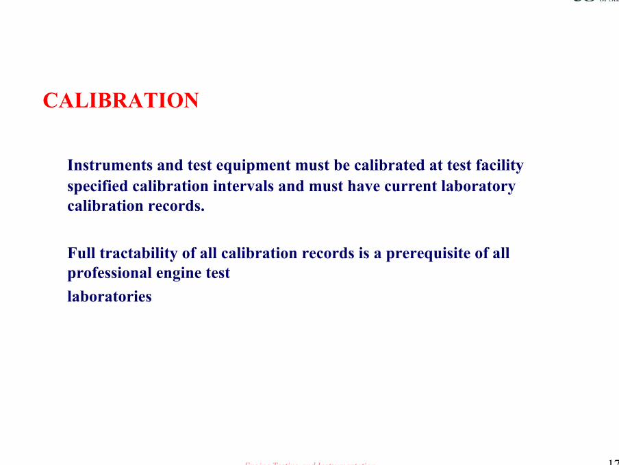
CALIBRATION
Instruments and test equipment must be calibrated at test facility specified calibration intervals and must have current laboratorycalibration records.
Full tractability of all calibration records is a prerequisite of all professional engine testlaboratories
Engine Testing and Instrumentation 18
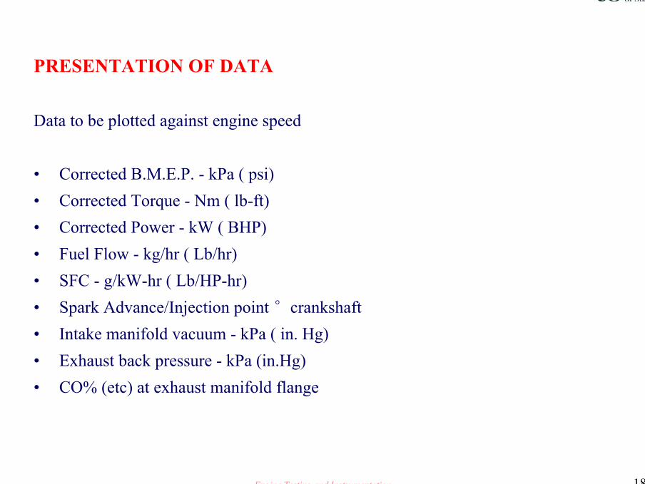
PRESENTATION OF DATA
Data to be plotted against engine speed
• Corrected B.M.E.P. - kPa ( psi)• Corrected Torque - Nm ( lb-ft)• Corrected Power - kW ( BHP)• Fuel Flow - kg/hr ( Lb/hr)• SFC - g/kW-hr ( Lb/HP-hr)• Spark Advance/Injection point °crankshaft• Intake manifold vacuum - kPa ( in. Hg)• Exhaust back pressure - kPa (in.Hg)• CO% (etc) at exhaust manifold flange
Engine Testing and Instrumentation 19
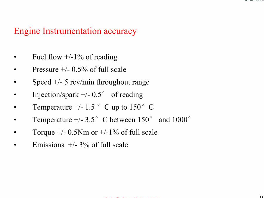
Engine Instrumentation accuracy
• Fuel flow +/-1% of reading• Pressure +/- 0.5% of full scale• Speed +/- 5 rev/min throughout range• Injection/spark +/- 0.5° of reading• Temperature +/- 1.5 °C up to 150°C• Temperature +/- 3.5°C between 150° and 1000°• Torque +/- 0.5Nm or +/-1% of full scale• Emissions +/- 3% of full scale

Engine Testing and Instrumentation 20
TAKING READINGS
• Allow engine to stabilize at each set point• Oil and coolant temperatures to be held constant to pre-determined
limits• Allow a minimum of 5 minutes between each set of readings• Instigate fuel and emission readings at the end of the stabilization
period

Engine Testing and Instrumentation 21
MAXIMUM POWER ~ PERFORMANCE TEST~ WOT PC
# Always complete a rough hand drafted graph of the results.# Is the fuel delivery a straight line ?# Do the SFC and Torque curves mirror each other# Build up your own key rules for further reference
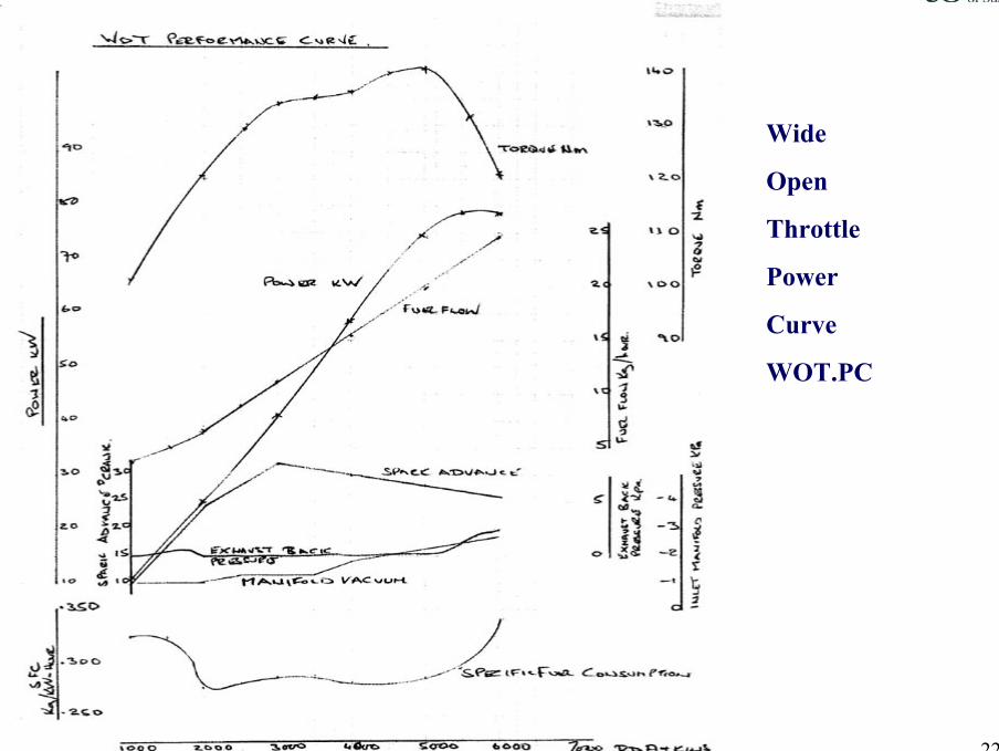
Engine Testing and Instrumentation 22
Wide
Open
Throttle
Power
Curve
WOT.PC
Engine Testing and Instrumentation 23
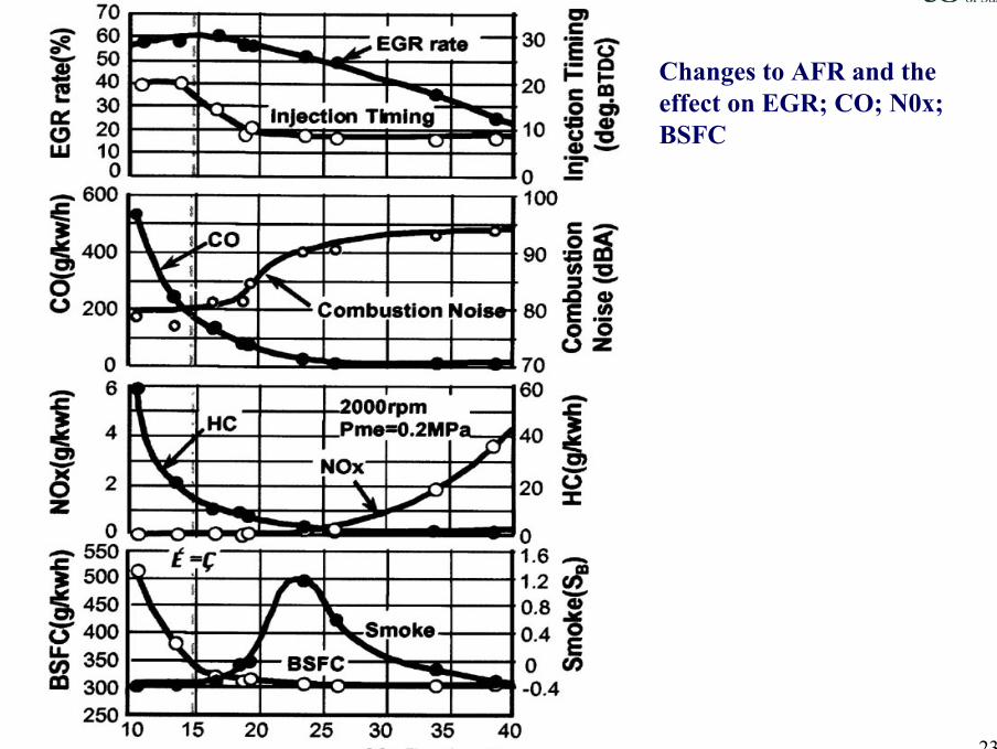
Changes to AFR and the effect on EGR; CO; N0x; BSFC
Engine Testing and Instrumentation 24
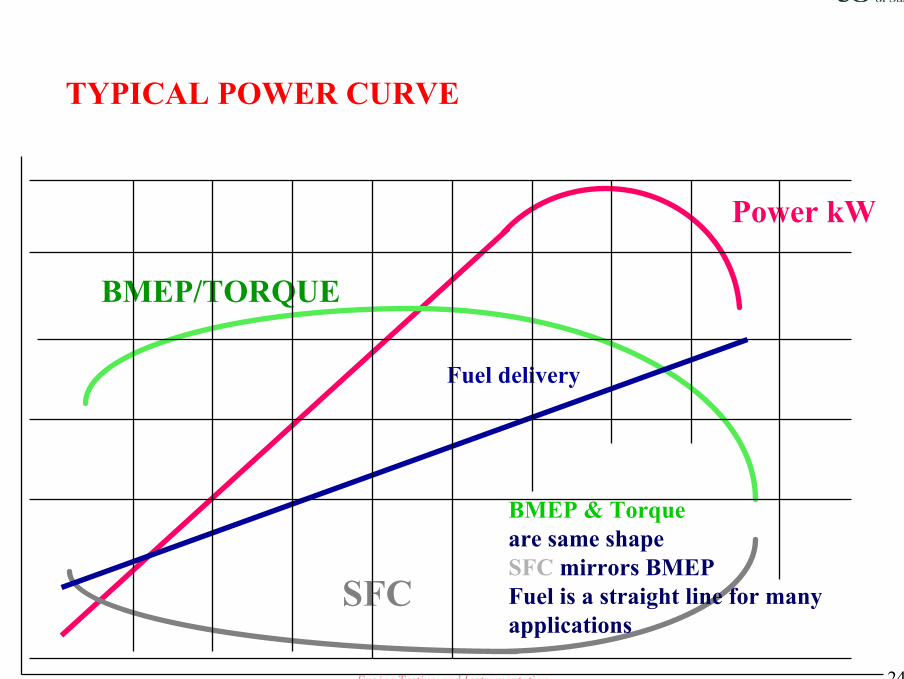
TYPICAL POWER CURVE
Power kW
BMEP/TORQUE
SFC
Fuel delivery
BMEP & Torqueare same shapeSFC mirrors BMEPFuel is a straight line for manyapplications
Engine Testing and Instrumentation 25
Effects of air/fuel ratio/Gasoline engines
• Air fuel ratio; mass of air in charge to mass of fuel• Stoichiometric ratio;the ratio where there is exactly sufficient O2
present for complete combustion ; Ranges 14: to 15:1~ 14.7:1 is the accepted norm.
• Lambda excess air factor, the ratio of actual to stoichiometric air/fuel ratio. The range is from 0.6 (rich) to 1.5(weak)
• Lambda ratio has a great influence on power, fuel consumption and emissions.
Engine Testing and Instrumentation 26
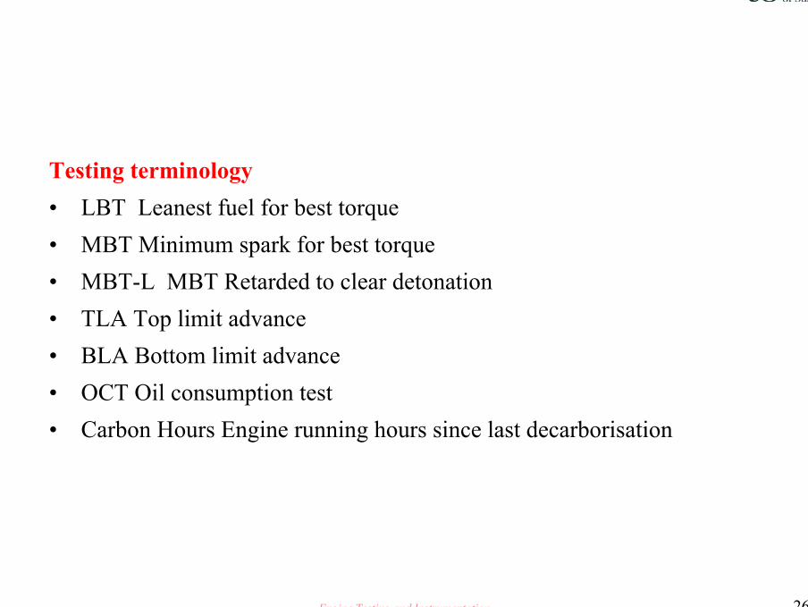
Testing terminology• LBT Leanest fuel for best torque• MBT Minimum spark for best torque• MBT-L MBT Retarded to clear detonation• TLA Top limit advance• BLA Bottom limit advance• OCT Oil consumption test• Carbon Hours Engine running hours since last decarborisation

Engine Testing and Instrumentation 27
Measurement of mechanical losses
• Indicator diagram• Motoring tests• Morse tests• Willans line
– We will consider the last three
Engine Testing and Instrumentation 28
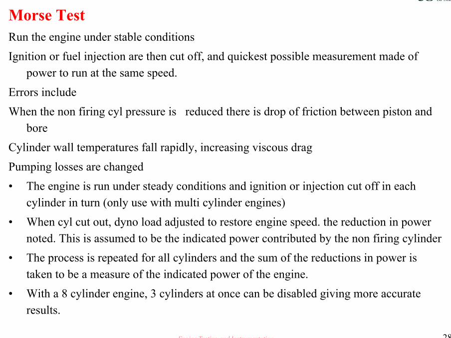
Morse TestRun the engine under stable conditionsIgnition or fuel injection are then cut off, and quickest possible measurement made of
power to run at the same speed.Errors includeWhen the non firing cyl pressure is reduced there is drop of friction between piston and
boreCylinder wall temperatures fall rapidly, increasing viscous dragPumping losses are changed• The engine is run under steady conditions and ignition or injection cut off in each
cylinder in turn (only use with multi cylinder engines)• When cyl cut out, dyno load adjusted to restore engine speed. the reduction in power
noted. This is assumed to be the indicated power contributed by the non firing cylinder• The process is repeated for all cylinders and the sum of the reductions in power is
taken to be a measure of the indicated power of the engine.• With a 8 cylinder engine, 3 cylinders at once can be disabled giving more accurate
results.

Engine Testing and Instrumentation 29
Morse Test
MECHANICAL EFFICIENCY BY MORSE TESTREV/MIN TOTAL IND Cyl No 1 Cyl No 2 Cyl No 3 Cyl No 4 Brake powe Friction Powe Mechanical
POWER kW kW kW kW kW kW kW efficiency %1000 9.08 2.29 2.25 2.27 2.28 7.86 1.22 861500 16.15 3.86 4.19 4.27 3.82 13.32 2.83 822000 22.83 5.72 5.68 5.76 5.68 19.02 3.81 832500 28.12 7.12 6.91 6.99 7.09 24.50 3.61 873000 36.00 9.13 8.91 8.97 9.00 29.95 6.05 833500 42.40 10.77 10.48 10.52 10.63 35.18 7.22 824000 50.68 12.88 12.50 12.71 12.59 40.73 9.95 804500 58.05 14.70 14.37 14.56 14.42 44.43 13.62 765000 63.56 16.34 15.76 16.02 15.45 46.70 16.86 735500 69.74 18.00 17.25 17.42 17.08 48.98 20.76 706000 75.83 19.54 18.66 18.91 18.72 50.14 25.70 66
The average mechanical efficiency is 79.31%
Engine Testing and Instrumentation 30
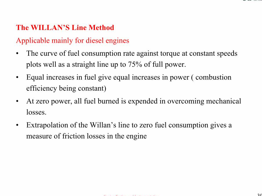
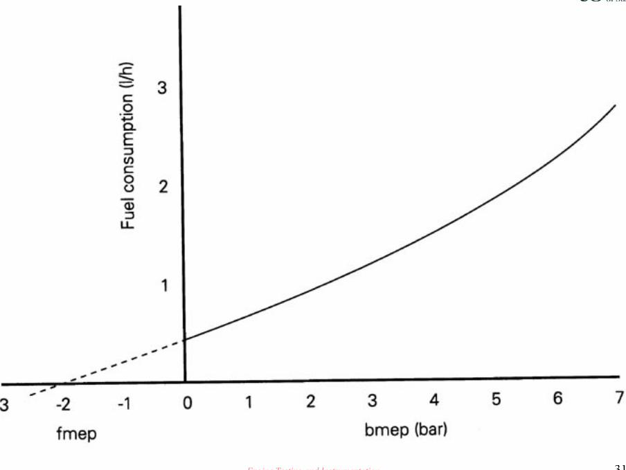
The WILLAN’S Line Method
Applicable mainly for diesel engines
• The curve of fuel consumption rate against torque at constant speeds plots well as a straight line up to 75% of full power.
• Equal increases in fuel give equal increases in power ( combustion efficiency being constant)
• At zero power, all fuel burned is expended in overcoming mechanical losses.
• Extrapolation of the Willan’s line to zero fuel consumption gives a measure of friction losses in the engine
Engine Testing and Instrumentation 31
Engine Testing and Instrumentation 32
Diesel - Cetane Number ~ recap
Cetane number is the most important diesel fuel specification. It is an indication of the extent of ignition delay.
The higher the cetane number the shorter the ignition delay, the smoother the combustion and the cleaner the exhaust
Cold starting is easier the higher the cetane number
Engine Testing and Instrumentation 33
Calorific value ~ recap
The calorific value of diesel fuel is lower than that of gasoline.Diesel fuel ranges from 40MJ/kg to 43MJ/kg and is a function of fuel
density The higher the sulphur content the lower the calorific value, this has a big
impact upon new emission regulations
Engine Testing and Instrumentation 34
CONFIDENCE
NEED TO REPEAT ALL PERFORMANCE TESTS
• In order to have statistical confidence in the results of any performance test, it is necessary to the repeat the test at least twice, if possible three times
Engine Testing and Instrumentation 35
DESIGN LEVEL ONE STANDARD DVT TESTS
Full load cycle test
Thermal shock test
Exhaust manifold crack tests
Valve wear cycle tests
General usage cycle test
Critical speed tests
Engine Testing and Instrumentation 36
DESIGN LEVEL TWOSTANDARD DVT TESTS
TESTS AS PER DESIGN LEVEL ONE
• THE NUMBER OF TESTS AND THE DURATION OF EACH TEST INCREASED.
• IN FIELD DURABILITY TESTS START
Engine Testing and Instrumentation 37
OFF TOOL VALIDATION COST SAVINGS
Intelligent interpretation of tests
Ensure that all tests produced to the highest standards
Produce significant savings in the period between design concept and production sign off
Engine Testing and Instrumentation 38
VALUE FOR MONEY
To achieve the maximum value from any DVT work, the measurement and assessment of critical components pre and post test is a prerequisite.
This assessment would include the measurement of wear, rating of component condition and analysis of fluids and lubricant.
This data enables the engineer to undertake predictive analysis of wear rates [ Re Bath Tub !] and thus to increase his confidence level in the validity of the test results and thus reduce the total number of tests to be undertaken
Engine Testing and Instrumentation 39
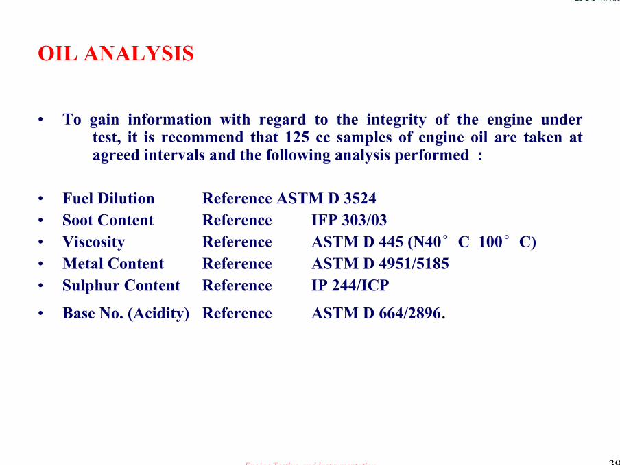
OIL ANALYSIS
• To gain information with regard to the integrity of the engine under test, it is recommend that 125 cc samples of engine oil are taken at agreed intervals and the following analysis performed :
• Fuel Dilution Reference ASTM D 3524• Soot Content Reference IFP 303/03• Viscosity Reference ASTM D 445 (N40°C 100°C)• Metal Content Reference ASTM D 4951/5185• Sulphur Content Reference IP 244/ICP
• Base No. (Acidity) Reference ASTM D 664/2896.
Engine Testing and Instrumentation 40
Engine Application
• Objective is to establish the probability of a given product reaching its design life which in turn may be dictated by legislation
• Bench tests must replicate and accelerate in service life conditions• A typical representative test cycle for all engine applications is not possible• Specialist tests have been developed to test engines over the 4 most important
operating conditions
Engine Testing and Instrumentation 41
Your place in the equation
• Get the maximum value out of each test
• The importance of the technicians place within the automotive industry cannot be too highly stressed.
• It is the fine attention too detail that makes the difference between a successful new model and a dead duck
Engine Testing and Instrumentation 42
Your responsibility
• Accuracy and Attention to detail must become a way of life for you
• You are a professional and are on the ladder to becoming a chartered engineer
• You must do all in your power to ensure that the results you produce are correct ~ this is not as simple as it sounds
Engine Testing and Instrumentation 43
Quality in Engine Testing
• Quality is important to both the customer and the supplier, without it the two are unlikely to meet again
• In engine testing, quality has a huge significance
• There are three considerations when defining ‘Quality’– The product meets the clients needs– The product is produced at the agreed cost– The goals are achieved in the agreed time
Engine Testing and Instrumentation 44
The principle considerations for test technicians and engineers alike is that the engine test must have the following attributes:
1. Accuracy.2. . Consistency3. . Repeatability4. Quality Workmanship
The customer must get what it is paying for, and everyone involved in the provision of this must understand what the customer is expecting to get.
Most ‘Quality Accreditation’ audits examine the whole operation to establish that all involved are aware of their role in meeting the standards
Engine Testing and Instrumentation 45
Quality Standards
QUALITY IENGINE TESTINGWithin the Test Industry the Quality Standards that are applicable in other
industries have a ‘Stay in Business’ implication for Test Laboratories.
For all Quality Standards a company is accredited to, the accredited bodies i.e. BSI, LQRA or UKAS will ensure compliance by visiting them as follows: -a) Surveillance visits every 6 months, this will involve the body auditing parts of
the Quality System in rotation.b) Re-Certification every 3 years, this will involve the body auditing every part of
the Quality System.
Engine Testing and Instrumentation 46
BS EN ISO9000 Series
• The ISO 9000 series sets out the methods that can be implemented in an organisation to ensure customers’ requirements are fully met. Not only does a fully documented quality management system ensure the customers’requirements are met, but the organisation’s requirements will also be met, both internally and externally and at an optimum cost. This is the result of efficient utilisation of the available resources - material, human and technological.
• This Quality Standard covers the whole operation of the company, which includes methods and procedures that a company commits to follow in order to Assure Quality of their service or product that they are supplying to customers.
Engine Testing and Instrumentation 47
BS EN ISO9000 Series
The ISO standard is endorsed by Lloyd’s Register Quality Assurance (LRQA) or by British Standard Institute (BSI) and is a national standard. The standard covers things like,
i. Customer initial contact through to invoicing proceduresii. Service or product tracking through the company proceduresiii. Service or product ‘Quality Control’ proceduresiv. Quality Auditing systemsv. Customer concern, follow up procedures etc., etc.
When a company is accredited to BS EN ISO 9000 it is for the entire engine test operation.
Engine Testing and Instrumentation 48
UKAS (EN 4501)
The United Kingdom Accreditation Service (UKAS) is recognised by the UK Government as the body responsible for the assessment and accreditation of organisations performing testing. UKAS was formed in 1995 as a company limited by guarantee by the merger of the National Measurement Accreditation Service (NAMAS) and the National Accreditation Council for Certification Bodies.
Testing organisations that comply with the requirements of the NAMAS Accreditation Standard and regulations are granted NAMAS Accreditation by UKAS and are entitled to use the NAMAS logo.
The United Kingdom Accreditation Service is the body providing accreditation for companies operating in the engine testing industry, primarily testing engines, fuels, oils, additives and the components by measurement and sampling.

Engine Testing and Instrumentation 49
UKAS (EN 4501) [cont.]
What does it mean for Test Technicians?Test Laboratories are of necessity ‘quality environments’, as all the work
carried out is required to be traceable to a baseline of a knownstandard, for example,
i. Test Procedures are generally developed to a recognised Industry Standard and where the test results are required to have UKAS Accreditation, then a UKAS Accredited Test Procedure must be followed. This test procedure will be the same in any company wishing to offer that service to a customer seeking UKAS Accredited results.
ii. Calibrated equipment must be used to reduce the risk of introducing faulty data and information into the test results through inaccurate measurements or physical activities like torque down procedures.
Engine Testing and Instrumentation 50
UKAS (EN 4501) [cont.]
Documentation and records must be meticulously kept to record the stages and results of tests. These records provide trace-ability and are the basis of customer reports and the documentation will vary depending upon the test. In ‘meeting the clients needs’ the passage of information up and down the links within the test team is vital, and it begins for the technician with the test instructions. The technician must understand the clients objectives for the test, and how theengineer is proposing to achieve them, and therefore his / her role in the project.
Engine Testing and Instrumentation 51
UKAS (EN 4501) [cont.]
Total Preventative Maintenance (TPM) procedures will prevent the introduction of faults into tests, and help to minimise the causes of unnecessary down-time. Downtime being periods when the test has been stopped or interrupted for unforeseen reasons, (not adjustments or component changes written into the test procedures).
‘Downtime’ can cost the company as much as £1,000 per day for accredited tests in test bed income, as well as customer inconvenience. Often a five-minute task will prevent escalation into major causes of down time.
That is the essence of (TPM).
Engine Testing and Instrumentation 52
• Training of technicians towards a high basic standard is required to service the needs of the test industry, which is regularly operating at or near the cutting edge of engine development.
This training together with an enhanced interest in the developments within the industry will provide the basis of a good technician / engineer.
UKAS (EN 4501) [cont.]
Engine Testing and Instrumentation 53
• Work practices and fitting skills are required to be of the highest standard in a highly competitive industry ‘Right First Time’ and forward thinking should be the absolute baseline for an engine test / build technicians work.
• Witness Reports are frequently generated by assessments conducted as part of the UKAS Accreditation ‘rules’ to continuously monitor the competence of those technicians who will carry out UKAS Accredited Test Procedures.
• The assessments should be looking at key skill areas within the test procedures (component replacement skills), test control equipment operation and use, and underpinning knowledge of the test aims and outcomes. An awareness of the Rating function will always add value to the technicians engine testing knowledge.
UKAS (EN 4501) [cont.]
Engine Testing and Instrumentation 54
Note
A worthwhile edict for all employees in the engine test industry to always bear in mind is this, :-
It takes years of hard work to build a good reputation, BUT it only takes seconds to destroy it!

Engine Testing and Instrumentation 55
The pressures that we engineers endure, they underline the need for effective testing.
Stringent Government Regulations
Customer Expectation
More Power
Improved Economy
Increased Engine Life
Lower Gaseous Emissions
Increased DevelopmentCosts
Need for Effective Testing
Professional Engineering Solutions

Engine Testing and Instrumentation 56
CALIBRATION
Calibration is all, regardless of the objectives of the test in question, all key items must be calibrated.
Failure to calibrate, makes the test worthless a waste of valuable time and money !
Engine Testing and Instrumentation 57
Calibration definitionsOperational range
The widest possible range of values ( min to max) anticipated for any given parameter for the duration of the test.
ParametersAll items with the potential of effecting the reported value. e.g. sensor, cable, signal conditioning etc
Calibration rangeThe range max to min over which the instrument should be calibrated
Full Scale Deflection FSDThe maximum value running back and through zero
Limits of Error( LOE)The maximum +/- error acceptable within the calibration standard
Engine Testing and Instrumentation 58
Calibration definitions
Accuracy of measurementThe closeness of the agreement between the result of a measurement and the true value of the measurement
Uncertainty of measurementResults of the evaluation aimed at characterising the range within which a true value of measurement is estimated to lie
TraceabilityThe property of a result of a measurement whereby it can be related to approximate measurement standards (National or International) through an unbroken chain of comparison.
Engine Testing and Instrumentation 59
Repeatability is KING !
In order to repeat any given test at some time in the future, it is essential that all variables are noted, for example:
– Engine build specification– Ignition and injection timing– Type of fuel, oil and coolant– Position of sensors on the engine and within the cell
Engine Testing and Instrumentation 60
Replicate test results
It will be impossible to replicate tests at some time in the future if one does not have full records of engine build, cam timing, ignition and injection timing, compression ratio, fuel,oil and coolant used.
The more data, the better you sleep at night!
Engine Testing and Instrumentation 61
Calibration Equipment Identification
Where possible all critical equipment shall be tagged or labelled with a serial number, frequency of calibration and calibration status shown on the tag or label.
Calibration for all elements critical to the utility of the test should always be traceable to National Standards. The frequency of calibration should be determined by a scientific approach paying due attention to the past behaviour of the measurement system used. Evidence of calibration should be readily discerned on all measurement equipment. Wherever possible the calibration of each parameter should be performed with reference to the whole measurement system. Calibration should include all instrumentation between the physical quantity being measured and the point at which data is logged for use with the test report. For example, calibration of a temperature sensor would require the sensor to be placed in a temperature- controlled bath and the measurement recorded employing the instrumentation used during test.

Engine Testing and Instrumentation 62
Definitions
Operational Range; -The widest possible range of values (difference between the maximum and
minimum values), anticipated to be seen for any given parameter throughout the duration of the test.
Parameter / measuring chain; -All items of hardware or virtual with the potential to affect the reported value in
engineering units. For example; -sensor, cable, signal conditioning and display / logging resolution.
Parameter Calibration Range; -The maximum recommended range over which each specific parameter should be
calibrated.
Engine Testing and Instrumentation 63
Definitions (cont.)Calibration Range; -The range (minimum to maximum), over which each specific parameter /
measuring chain is calibrated should exceed the operating range.
Full Scale Deflection (FSD); -The maximum single sided values for each measuring chain having a calibrated range intercepting at or through zero.
Limits of Error (LOE); -The maximum +/- error acceptable with reference to the calibration transfer
standard. The defined ‘Limits of Error’ excluding uncertainty errors associated with the calibration transfer standard and method of calibration.
Engine Testing and Instrumentation 64
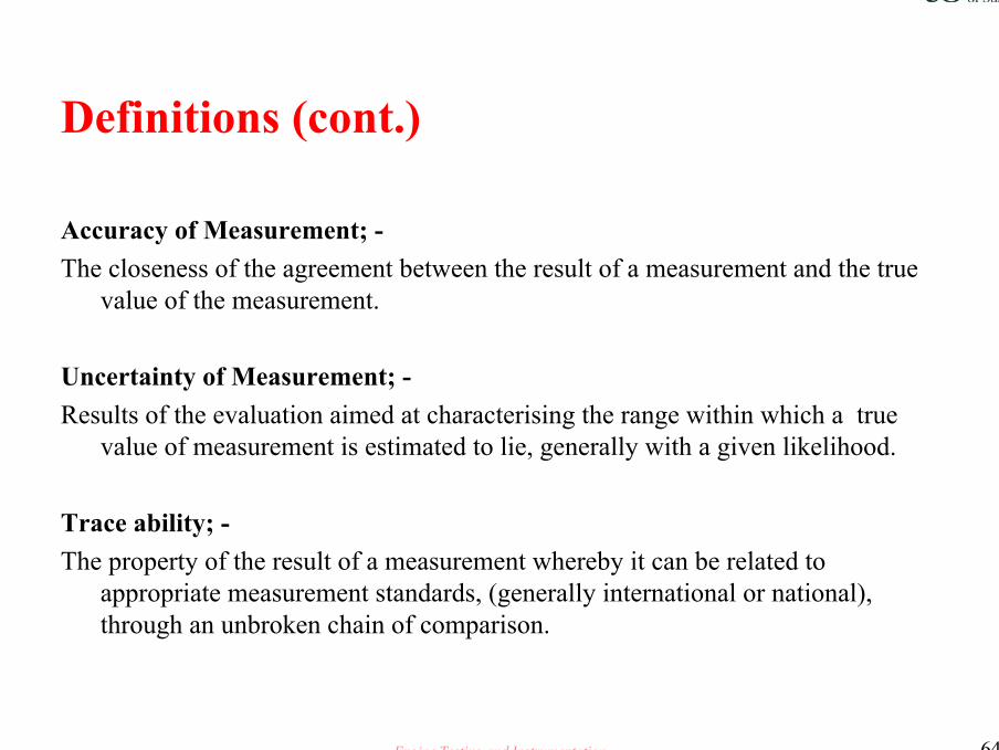
Definitions (cont.)
Accuracy of Measurement; -The closeness of the agreement between the result of a measurement and the true
value of the measurement.
Uncertainty of Measurement; -Results of the evaluation aimed at characterising the range within which a true
value of measurement is estimated to lie, generally with a given likelihood.
Trace ability; -The property of the result of a measurement whereby it can be related to
appropriate measurement standards, (generally international or national), through an unbroken chain of comparison.
Engine Testing and Instrumentation 65
Calibration Personnel and Equipment
All personnel carrying out calibration should be adequately trained, and regularly reviewed to assess their competence with the calibration equipment and procedures.
All the channels defined as a critical calibration parameter must be calibrated using equipment that is fit for that purpose, and traceable to National Standards. Equipment records must be kept detailing the history of all Calibration Standards used.
11.10.2006 Richard D Atkins
Engine Testing and Instrumentation 66
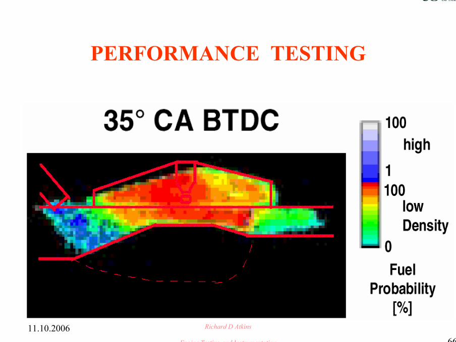
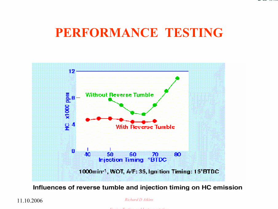
PERFORMANCE TESTING
11.10.2006 Richard D Atkins
Engine Testing and Instrumentation 67
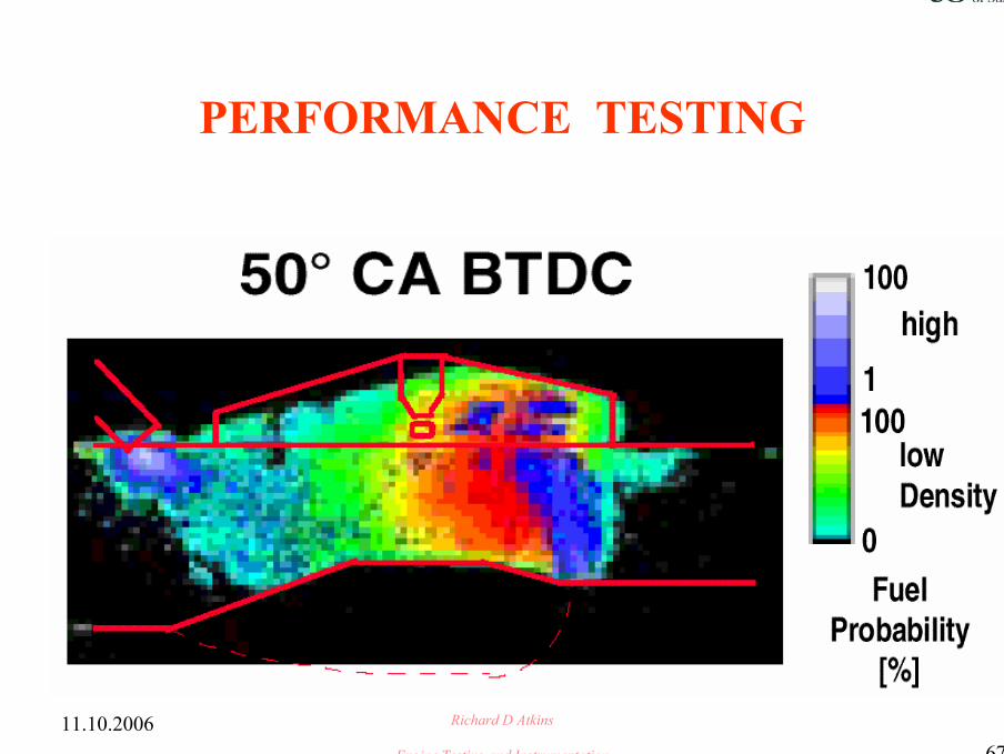
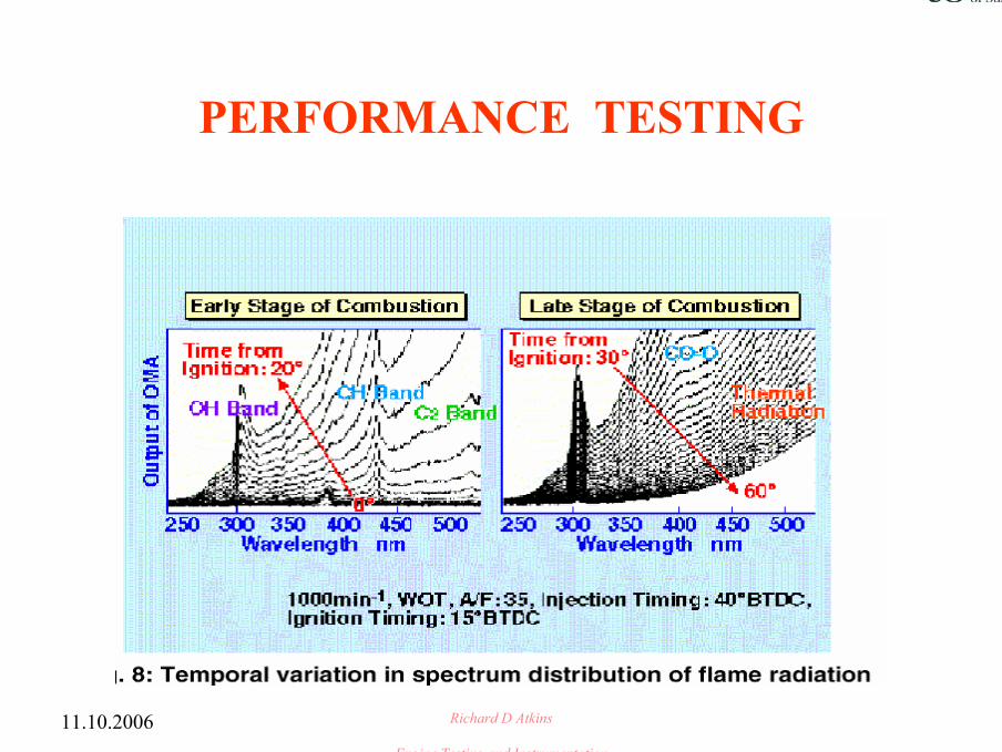
PERFORMANCE TESTING
11.10.2006 Richard D Atkins
Engine Testing and Instrumentation 68
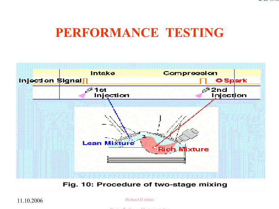
PERFORMANCE TESTING
11.10.2006 Richard D Atkins
Engine Testing and Instrumentation 69
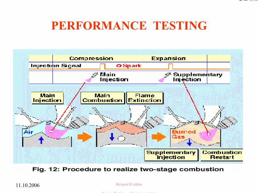
PERFORMANCE TESTING
11.10.2006 Richard D Atkins
Engine Testing and Instrumentation 70
PERFORMANCE TESTING
11.10.2006 Richard D Atkins
Engine Testing and Instrumentation
PERFORMANCE TESTING
11.10.2006 Richard D Atkins
Engine Testing and Instrumentation
PERFORMANCE TESTING
11.10.2006 Richard D Atkins
Engine Testing and Instrumentation
PERFORMANCE TESTING
11.10.2006 Richard D Atkins
Engine Testing and Instrumentation
PERFORMANCE TESTING
11.10.2006 Richard D Atkins
Engine Testing and Instrumentation
PERFORMANCE TESTING

11.10.2006 Richard D Atkins
Engine Testing and Instrumentation
PERFORMANCE TESTING
11.10.2006 Richard D Atkins
Engine Testing and Instrumentation
PERFORMANCE TESTING
11.10.2006 Richard D Atkins
Engine Testing and Instrumentation
PERFORMANCE TESTING
11.10.2006 Richard D Atkins
Engine Testing and Instrumentation
PERFORMANCE TESTING
11.10.2006 Richard D Atkins
Engine Testing and Instrumentation
PERFORMANCE TESTING
Engine Testing and Instrumentation 81
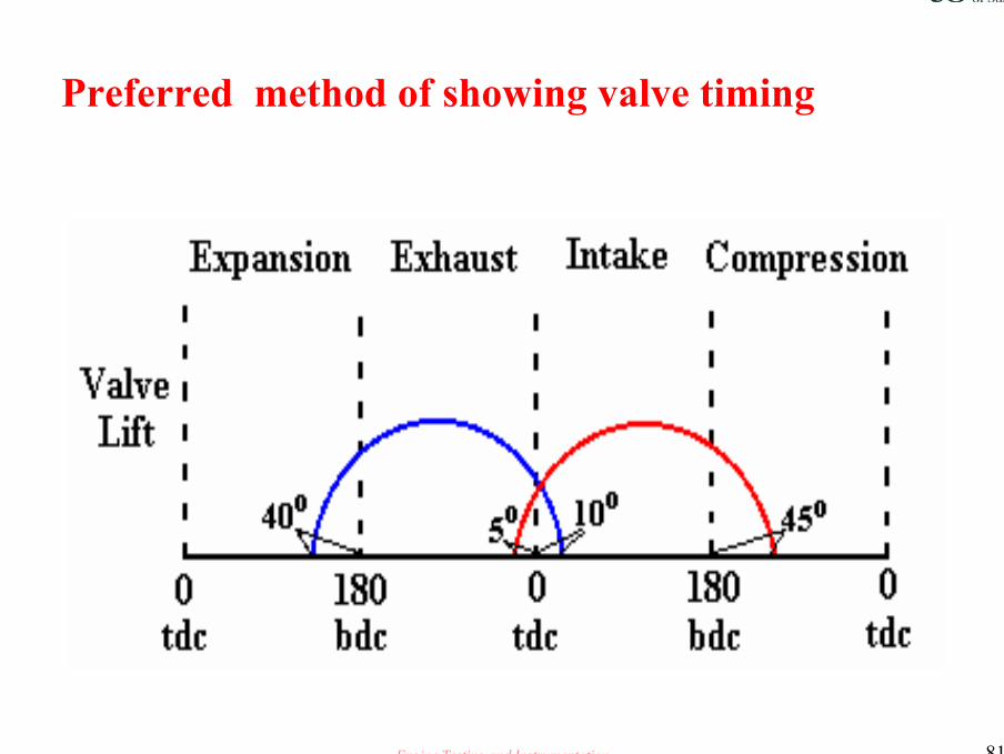
Preferred method of showing valve timing