eti 09 testingprecedure - university of...
TRANSCRIPT
Engine Testing and Instrumentation 1
Testing Testing ProcedureProcedure

Engine Testing and Instrumentation 2
Repeatability is KING !
In order to repeat any given test at some time in the future, it is essential that all variables are noted, for example:
– Engine build specification– Ignition and injection timing– Type of fuel, oil and coolant– Position of sensors on the engine and within the cell
It will be impossible to replicate tests at some time in the future if one does not have full records of engine build, cam timing, ignition and injection timing, compression ratio, fuel,oil and coolant used.

Engine Testing and Instrumentation 3
Calibration Equipment Identification
Where possible all critical equipment shall be tagged or labelled with the serial number, frequency of calibration and calibration status shown on the tag or label.
Engine Testing and Instrumentation 4
Engine Tests used within the testing industry:
• Durability (Design Validation Test) Within this group is;• Steady load and speed operation• Load cycling• Speed cycling• Thermal shock cycling• Component development• Vehicle cycle simulation

Engine Testing and Instrumentation 5
Performance, Within this group is;
• · Power curves• · Governor curves• · Lubrication oil consumption• · Flow measurements• · Heat balance• Emissions measurement
–

Engine Testing and Instrumentation 6
Lubricants & Fuels Within this group is;
• Automotive lubricants• Marine lubricants• Black sludge formation• Intake valve deposits
• Combustion chamber deposits
Engine Testing and Instrumentation 7
Specialised investigations and testing Within this group is:
• Rig testing (bearings, antifreeze, erosion etc.)• Simulated or environmental testing• Photo elastic stress measurements• Strain gauge testing• Flywheel burst testing
Engine Testing and Instrumentation 8
Exhaust system testing Within this group is:
• Vehicle cycle simulation• Steady state

Engine Testing and Instrumentation 9
Catalyst ageing Within this group is:
• Vehicle cycle simulation• Steady state• Accelerated ageing• Light off efficiency tests• Sulphate release tests
Engine Testing and Instrumentation 10
Transient testing
• Fully transient tests and indeed automatic mapping software programmes are disciplines worthy of additional study, however, in order to glean the maximum useful repeatable data from all forms of transient testing, it is essential to have a full understanding and experience of steady state test types. Mathematical modelling ofengine functions is an essential element in the design and development of new engine types. It is the accurate cross correlation of modelled data with actual running data that enables the leading manufacturers to rapidly move ahead of the opposition and obtain clear market gains.
Engine Testing and Instrumentation 11
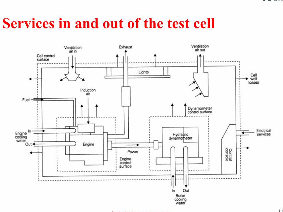
Services in and out of the test cell
Engine Testing and Instrumentation 12
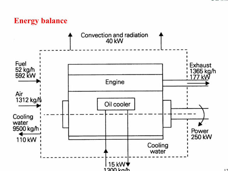
Energy balance
Engine Testing and Instrumentation 13
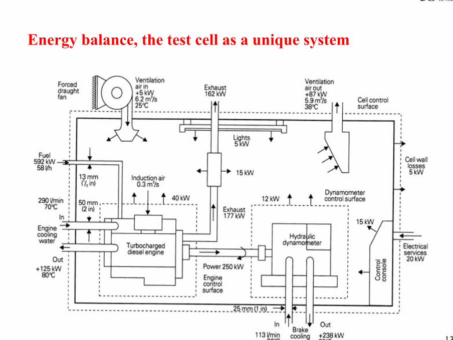
Energy balance, the test cell as a unique system

Engine Testing and Instrumentation 14
Typical test arrangement

Engine Testing and Instrumentation 15
Installation within the test cell
PalletQA ~ InstructionsDocumentationItems usedAlignmentDrive shaftsContainment

Engine Testing and Instrumentation 16
Installation in the test cell
Engine Testing and Instrumentation 17
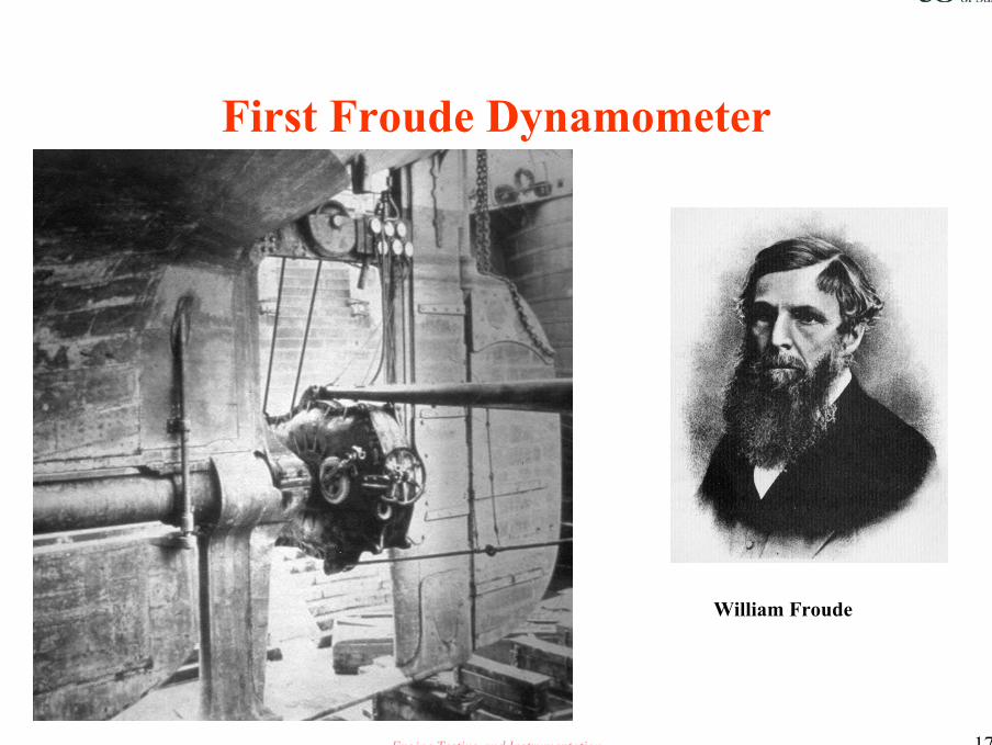
First Froude Dynamometer
William Froude

Engine Testing and Instrumentation 18
Typical test cell
T
Fuel Air Inlet
Radiated Heat
Coolant out
Coolant inPower unit
Oil cooler
Oil cooler water
Radiated heat
Air into cell Extraction air
Radiated heat from dynamometer surfaces
Dynamometer
The energy balance within the cell, items to consider:-
Radiated heat from engine and exhaust
Radiated heat from the dynamometer
Cell wall losses, heat and sound energy
Coolant flows to engine and dynamometer
Lighting and electrical items within the cell, spot fan coolers etc
Control console module

Engine Testing and Instrumentation 19
Energy balance
The energy balance of a 75kW turbocharged diesel engine is as follows:
In OutFuel 176.53kW Power 75kW (42.2%)
Heat to coolant 33kW(18.6%)Heat to oil 4.5kW (2.5%)Heat to exhaust 53.1 kW (29.9%)Convection & radiation11kW (6.8%)
TOTALS 176.53kW 176.53kW
Engine Testing and Instrumentation 20
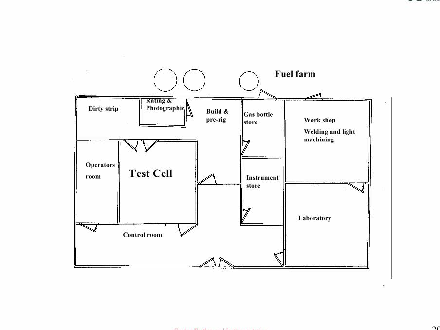
Test Cell
Dirty stripRating & Photographic Build &
pre-rig
Operators
room
Control room
Fuel farm
Gas bottle store Work shop
Welding and light machining
Laboratory
Instrument store

Engine Testing and Instrumentation 21

Engine Testing and Instrumentation 22

Engine Testing and Instrumentation 23

Engine Testing and Instrumentation 24
Scribed and plumb Lines
Engine Testing and Instrumentation 25
Test Types
DurabilityPerformanceLubricant and FuelExhaust systemsCatalyst ageingSpecialist investigations

Engine Testing and Instrumentation 26
Types of Validation Test
Tests should ideally replicate in service lifeIt is necessary to accelerate the testingA representative cycle for all engines is not possibleThere are however a number of discrete running conditions which give the most arduous conditions for key componentsSome applications are simple, for example off highway generating set applications
Lister Petter

Engine Testing and Instrumentation 27
Specifying Validation tests
Three aspects need to be considered I. Verify that wear will not prevent the designed life
being achievedII. Verify that mechanical fatigue failure does not occur
within the designed lifeIII. Verify that thermal fatigue failure does not occur
within the designed life

Engine Testing and Instrumentation 28
Validation duty cycles
To cater for the majority of cases and to ensure that components are assessed under the most severe operating conditions, it is usual to specify a test cycle that incorporates one the four extreme conditions we discussed earlier
The engine build and installation on the test bench should replicate that of the vehicle

Engine Testing and Instrumentation 29
Engineering limits of materials
The endurance limit for typical engineering materials is quoted as being between 106 and 107 cyclesIn a four stroke engine, a complete load cycle occurs once every two revolutions ( 720°)107 cycles would occur after 166 running hours at a rated speed of 2000 rev/min.

Engine Testing and Instrumentation 30
The first jet airliner, the Comet (shown below), was launched in Britain in 1949.
107 low amplitude cycles and the wings fell off in 1950 !

Engine Testing and Instrumentation 31
Optica
Mike Hewland engine based on F1 go cart application. Propellorcame adrift killing two policemen.
Material fatigue problem.

Engine Testing and Instrumentation 32
Designing a test based upon mechanical fatigue
The test cycle for a 1000 hour test would be:Test cycles
2 x 10 @ full load and speed4 x 106@ idle1.6x 107 @ maximum torque1.065x107 governor run out speedA total of 5x 10⁷ cyclesThis test would demonstrate a high degree of confidence with respect to mechanical fatigue
Engine Testing and Instrumentation 33
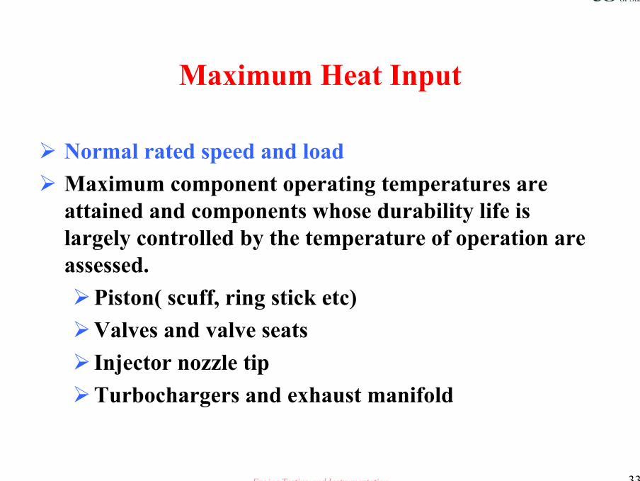
Maximum Heat Input
Normal rated speed and loadMaximum component operating temperatures are attained and components whose durability life is largely controlled by the temperature of operation are assessed.
Piston( scuff, ring stick etc)Valves and valve seatsInjector nozzle tipTurbochargers and exhaust manifold

Engine Testing and Instrumentation 34
Maximum cyclic temperature variation
Thermal fatigueFound when the engine is operated between conditions of maximum and minimum heat input ( Running rated speed and load down to idle)Assess components whose durability is determined by the ability to withstand thermal fatigue
Cylinder head assemblyPistonsManifolds, fixingsTurbocharger

Engine Testing and Instrumentation 35
Thermal shock test

Engine Testing and Instrumentation 36
Thermal Shock Tests
Engine Testing and Instrumentation 37
Maximum imposed mechanical load
Operating at maximum power and rated speedWith a turbo-charged diesel engine, this condition is normally encountered at maximum torque where the cylinder pressure is at a maximum and the lower operating speed leads to lower inertia relief.Components assessed include:
Small endBig endMain bearingsPistonLinerCrankshaft
Engine Testing and Instrumentation 38
Maximum dynamic load
High inertia, maximum engine speed, low load. ( Diesel application governor run out )Maximum stresses are applied to:
Valve train componentsCamshaftCam followersValvesSprings

Engine Testing and Instrumentation 39
Basic ValidationTest Cycle
Many manufactures increase the severityof their tests over what is found in normal service. Over speed, over fuelling etc.
Rated load and Speed 20 minNo Load Governor run out 10 minMaximum Torque 20 minIdle 10 min
Engine Testing and Instrumentation 40
Predictive Analysis a durability/validation test tool
To be able to predict when a component will fail due to fatigue or wear out is a prerequisite to day.This can be achieved by:
Accelerated rig testing of key componentsIntelligent design validation testing with much attention paid to pre and post test strip, examination and measurement of critical components, regular lubricating oil analysis and exhaust gas particulate speciation are all valuable tools used in predictive analysis studies.

Engine Testing and Instrumentation 41
Predictive Analysis ‘The How’ Typical example
1000 hour validation test. On the post test strip and measurement, it was noted that one cylinder bore has indications of wear and scuffing.It was noted that the particular cylinder top compression ring was wornAnalysis of the oil samples taken at 50 hour intervals clearly showed a high level of chromium and Iron in the first 50 hour sample, there after no significant levels were noted.From this the engineer deduced that the cause was ingress of foreign matter in the top piston ring groove which was dislodged at some time within the first 50 hours of running.If however there had been chromium and iron in all 20 oil samples, then it would be possible to predict the projected life of the bore and indeed one would be able to alert the chief engineer to a possible coolant circulation problem leading to cylinder bore distortion.
Engine Testing and Instrumentation 42
Validation duty cycles
To cater for the majority of cases and to ensure that components are assessed under the most severe operating conditions, it is usual to specify a test cycle that incorporates one the four extreme conditions we discussed earlier
The engine build and installation on the test bench should replicate that of the vehicle

Engine Testing and Instrumentation 43
Automatic mapping
The trend toward automatic mapping is a ongoing cause for concern.There are many and disparate variables to be considered, for example
Fuel and ignition timing and durationVariable valve timingVariable Induction lengthVariable EGRVariable boost

Engine Testing and Instrumentation 44
Automatic mapping
Changing many parameters simultaneously runs contrary to the engineers training , the mantra was change one thing at a time.Times have changed, and we must use the available tools effectivelyIn order to be able to identify major errors in Automatic mapping data, it is essential that the engineer has a deep understanding of the effect of individual parameter changes on all the associated outputs.Steady state loop studies in the running envelope are still required, and again when running the tests, warning bells should ring if the results are too good
Engine Testing and Instrumentation 45
ENGINE TESTING
GOLDEN RULES ~ Before a shaft turns !Know the precise build specification of the engine prior to start of test
It will be impossible to replicate tests at some time in the future if one does have full records of build, cam timing, ignition timing, fuel and oil used, compression ratio.
The more detail you have, the better you sleep at night !
Engine Testing and Instrumentation 46
ENGINE TESTING
GOLDEN RULES ~ Before a shaft turns!Before starting the test, be clear why you have instigated the testWhat do you hope to learnWhat are the key elements that you wish to glean from the testHave you told the test technician what is required and why

Engine Testing and Instrumentation 47
ENGINE TESTING
GOLDEN RULES ~ Before a shaft turns !
Write clear unambiguous test instructions
Discuss the test with the test technician
Consider a basic pencil graph to be produced by
the technician as the test progresses

Engine Testing and Instrumentation 48
ENGINE TESTING
GOLDEN RULES ~ Before a shaft turns !Calibrate , Calibrate , CalibrateRegardless of the objectives of the test, key items must be correct.
Indicated Load, Static and DynamicEngine Speed [rev/min]Dynamometer input shaft speed [rev/min]

Engine Testing and Instrumentation 49
ENGINE TESTING
GOLDEN RULES ~ The real World !!
Suspect all results
The better the apparent data the greater
the need for suspicion
Straight line trend curves do not happen in real
life

Engine Testing and Instrumentation 50
ENGINE TESTING
TAKING READINGSAllow engine to stabilise at each set point
Oil and coolant temperatures to be held constant to pre-determined limits
Allow a minimum of 5 minutes between each set of readings
Instigate fuel and emission readings at the end of the stabilisation period

Engine Testing and Instrumentation 51
ENGINE TESTING
Repeatability of testsIn order to be able to repeat test results, in addition to knowing the build of the engine, it is necessary to correct the results back to a standard induction temperature and barometric pressure within the test cellThere are various standards for N/A and turbo, diesel and gasoline applications

Engine Testing and Instrumentation 52
ENGINE TESTING
CALIBRATIONInstruments and test equipment must be calibrated at test facility specified calibration intervals and must have current laboratory calibration records.
Full tractability of all calibration records is a prerequisite of all professional engine testlaboratories
Engine Testing and Instrumentation 53
ENGINE TESTING
NEED TO REPEAT ALL PERFORMANCE TESTSIn order to have statistical confidence in the results of any performance test, it is necessary to the repeat the test at least twice, if possible three times.

Engine Testing and Instrumentation 54
Another GOLDEN RULE
DO IT ONCE
DO IT CORRECTLY EACH TIME, EVERY TIME
Engine Testing and Instrumentation 55
TESTING GOLDEN RULES
SUSPECT ALL RESULTS
CHECK AND CROSS CHECK CALIBRATION
ENSURE THAT YOU HAVE CLEAR UNAMBIGUOUS INSTRUCTIONS
RECORD ALL RESULTS THE GOOD AND THE BAD
Engine Testing and Instrumentation 56
What does performance testing give the engineer
• A means of comparing differing engine build specifications , one with another
• An aid to engine development from design level one to production sign off
• A production quality tool

Engine Testing and Instrumentation 57
Preferred method of showing valve timing

Engine Testing and Instrumentation 58
MAXIMUM POWER ~ PERFORMANCE TEST
# Always complete a rough hand drafted graph of the results.
# Is the fuel delivery a straight line ?# Do the SFC and Torque mirror each other# Build up your own memory joggers

Engine Testing and Instrumentation 59
PERFORMANCE TESTING
OKTHE RESULTS ARE BELIEVABLE
TREAT THESE RESULTS WITH CAUTION
NOT POSSIBLE RE-TEST !!
TREAT THESE RESULTS WITH CAUTION
Build up your own memory joggers

Engine Testing and Instrumentation 60
PERFORMANCE TESTING
AFR
FUEL
POWER
CO%
WHAT IS WRONG WITH THIS !!!!
CO

Engine Testing and Instrumentation 61
PERFORMANCE TESTING
• Repeatability of tests• In order to be able to repeat test results, in addition to
knowing the build of the engine, it is necessary to correct the results back to a standard induction temperature and barometric pressure within the test cell
• There are various standards for N/A and turbo, diesel and gasoline applications

Engine Testing and Instrumentation 62
PERFORMANCE TESTING
• Correction to 88/195/EEC
• Spark ignition
• Correction factor cf = [99] 1.2
[ T ]0.6
[ps ] x
[298]Where T=the absolute intake temp in Kelvinsps=dry atmospheric pressure in kilopascals kPa less the water
vapour pressureN.B. for the test to be valid, the correction factor must lay
between 0.93 and 1.07

Engine Testing and Instrumentation 63
PERFORMANCE TESTING
• Correction to 88/195/EEC• Diesel Compression ignition N/A
• Correction factor cf = [99] [ T ]0.7
[ps ] [298]Diesel Compression ignition Turbo
• Correction factor cf = [99] 0.7
[ T ]1.5
[ps ] x
[298]
Engine Testing and Instrumentation 64
PERFORMANCE TESTING
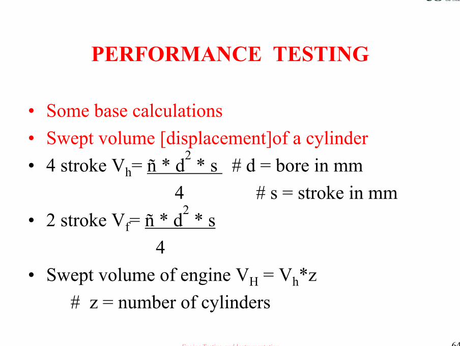
• Some base calculations• Swept volume [displacement]of a cylinder• 4 stroke Vh= ñ * d2 * s # d = bore in mm
4 # s = stroke in mm• 2 stroke Vf= ñ * d2 * s
4• Swept volume of engine VH = Vh*z
# z = number of cylinders
ñ
Engine Testing and Instrumentation 65
PERFORMANCE TESTING
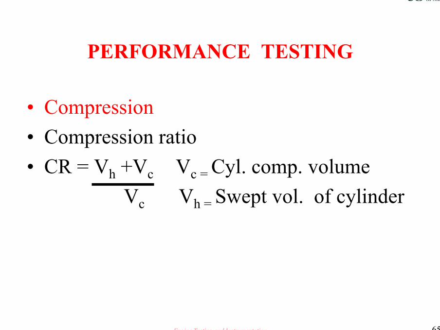
• Compression • Compression ratio• CR = Vh +Vc Vc = Cyl. comp. volume
Vc Vh = Swept vol. of cylinder

Engine Testing and Instrumentation 66
PERFORMANCE TESTING
• Gasoline applications ~ Ignition timing• Determination of ignition timing at differing speed and
load conditions• The test is conducted throughout a wide range of ignition
advance positions in order to determine engine performance levels with differing load conditions
Engine Testing and Instrumentation 67
PERFORMANCE TESTING
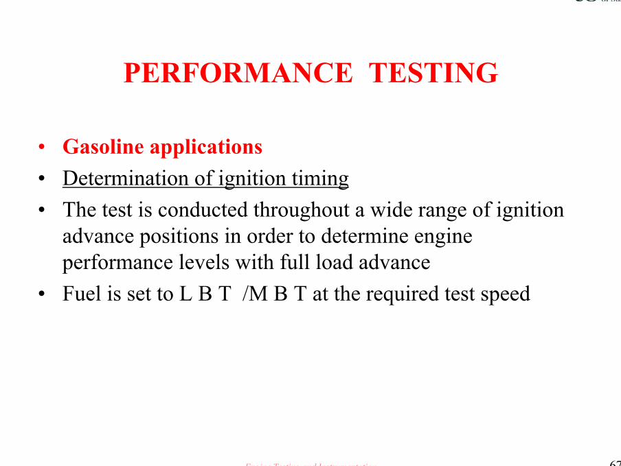
• Gasoline applications• Determination of ignition timing• The test is conducted throughout a wide range of ignition
advance positions in order to determine engine performance levels with full load advance
• Fuel is set to L B T /M B T at the required test speed

Engine Testing and Instrumentation 68
PERFORMANCE TESTING
• Determination of part load ignition timing• These tests are conducted to establish the points of
minimum specific fuel consumption relative to optimum spark advance.
• By running a series of loops throughout the speed range, and maintaining specified BMEP figures, a final part load ignition curve can be established

Engine Testing and Instrumentation 69
PERFORMANCE TESTING
• Determination of ignition timing ~ part load procedure :
• Set throttle position as required/select dynamometer constant speed mode.
• Establish MBT at required speed/load• Start loop, retard ignition by 14°/reset load with throttle• Allow conditions to stabilise

Engine Testing and Instrumentation 70
PERFORMANCE TESTING
Determination of ignition timing ~ part load procedure • Set throttle position as required/select dynamometer
constant speed mode.• Establish MBT at required speed/load• Start loop, retard ignition by 14°/reset load with throttle• Allow conditions to stabilise
Engine Testing and Instrumentation 71
PERFORMANCE TESTING
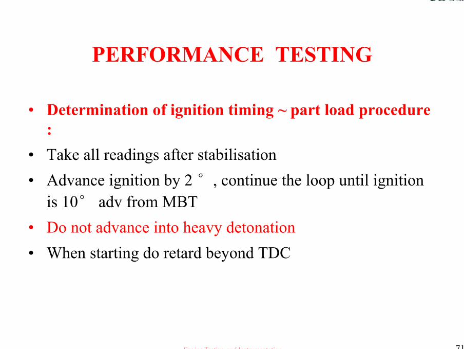
• Determination of ignition timing ~ part load procedure :
• Take all readings after stabilisation• Advance ignition by 2 °, continue the loop until ignition
is 10° adv from MBT• Do not advance into heavy detonation• When starting do retard beyond TDC

Engine Testing and Instrumentation 72
PERFORMANCE TESTING
Full load 1500 rev/min ignition loop
70
72
74
76
78
80
82
7.5 10 12.5 15 17.5 20 22.5 25 27.5
Spark Advance
Torq
ue N
m

Engine Testing and Instrumentation 73
Engine Testing and Instrumentation 74
PERFORMANCE TESTING
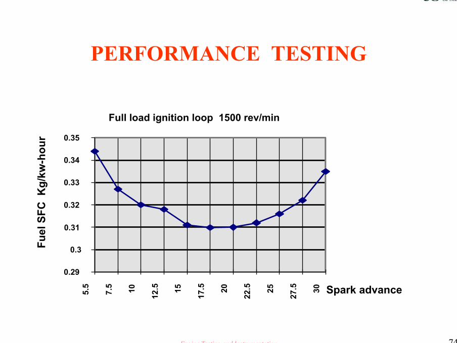
Full load ignition loop 1500 rev/min
0.29
0.3
0.31
0.32
0.33
0.34
0.35
5.5
7.5 10
12.5 15
17.5 20
22.5 25
27.5 30 Spark advance
Fuel
SFC
Kg/
kw-h
our

Engine Testing and Instrumentation 75
PERFORMANCE TESTING
Fuel loops constantthrottle setting
SFC
Fuel
1000 rev per min
1500 2000
2500
35003000
4000
Note: The minimum fuel/maximum torque pointat each fixed speed, givesa near straight line curvefor any given throttle setting
Fixed speedpoints
Manifold vacuum
Engine Testing and Instrumentation 76
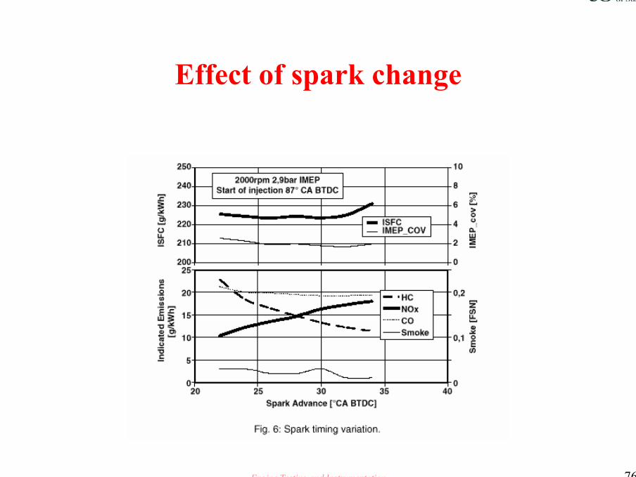
Effect of spark change
Engine Testing and Instrumentation 77
PERFORMANCE TESTINGEngine Instrumentation
• Air cleaner differential pressure• Boost ( if applicable) centre of inlet manifold• EGR Vacuum/pressure• EBP 75mm+/-10mm down stream of mating flange• Fuel supply pressure, +ve.. : -ve..• Intake manifold vacuum centre of manifold• Oil Pressure ; Engine gallery take off position• Temperature Thermocouples always as close to outlet/inlet
as possible in a position where flow is unrestricted• Fuel temperature, measure as close to the measuring head
as possible

Engine Testing and Instrumentation 78
PERFORMANCE TESTING
CALIBRATIONInstruments and test equipment must be calibrated at test facility specified calibration intervals and must have current laboratory calibration records.
Full tractability of all calibration records is a prerequisite of all professional engine testlaboratories
Engine Testing and Instrumentation 79
PERFORMANCE TESTING
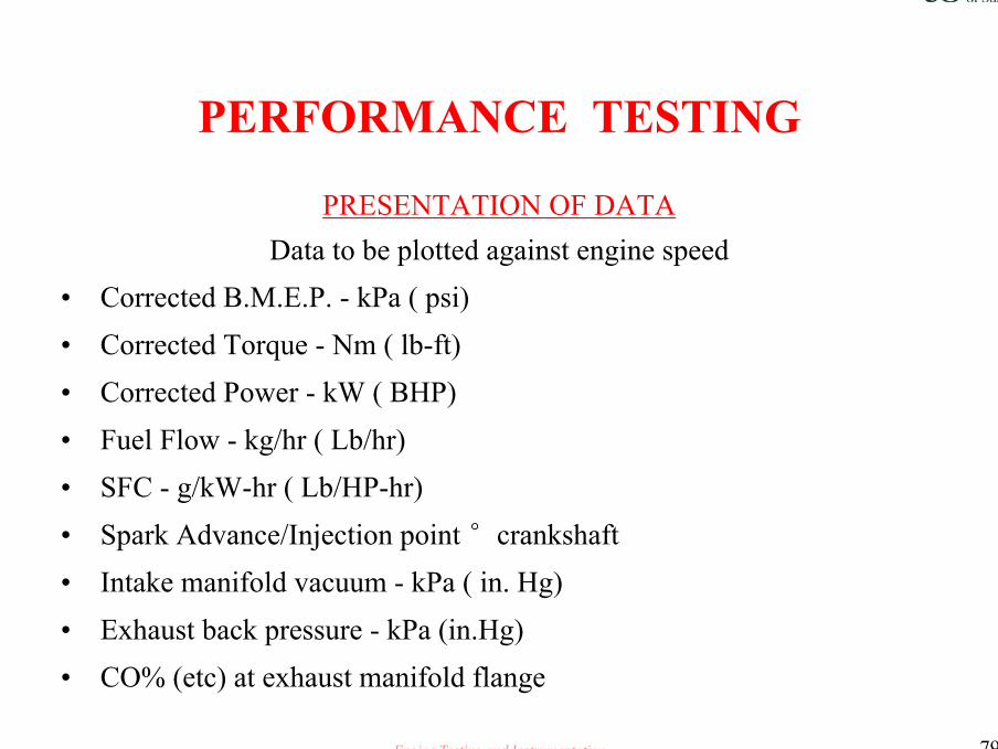
PRESENTATION OF DATAData to be plotted against engine speed
• Corrected B.M.E.P. - kPa ( psi)• Corrected Torque - Nm ( lb-ft)• Corrected Power - kW ( BHP)• Fuel Flow - kg/hr ( Lb/hr)• SFC - g/kW-hr ( Lb/HP-hr)• Spark Advance/Injection point °crankshaft• Intake manifold vacuum - kPa ( in. Hg)• Exhaust back pressure - kPa (in.Hg)• CO% (etc) at exhaust manifold flange

Engine Testing and Instrumentation 80
PERFORMANCE TESTING
Engine Instrumentation• ACCURACY
• Fuel flow +/-1% of reading
• Pressure +/- 0.5% of full scale
• Speed +/- 5 rev/min throughout range
• Injection/spark +/- 0.5° of reading
• Temperature +/- 1.5 °C up to 150°C
• Temperature +/- 3.5°C between 150° and 1000°
• Torque +/- 0.5Nm or +/-1% of full scale
• Emissions +/- 3% of full scale

Engine Testing and Instrumentation 81
PERFORMANCE TESTING
• TAKING READINGS• Allow engine to stabilise at each set point• Oil and coolant temperatures to be held constant to pre-
determined limits• Allow a minimum of 5 minutes between each set of
readings• Instigate fuel and emission readings at the end of the
stabilisation period
Engine Testing and Instrumentation 82
PERFORMANCE TESTING
• NEED TO REPEAT ALL PERFORMANCE TESTS• In order to have statistical confidence in the results of any
performance test, it is necessary to the repeat the test at least twice, if possible three times.

Engine Testing and Instrumentation 83
PERFORMANCE TESTING
• MAXIMUM POWER ~ PERFORMANCE TEST~ WOT PC# Always complete a rough hand drafted graph of the
results.# Is the fuel delivery a straight line ?# Do the SFC and Torque curves mirror each other# Build up your own key rules for further reference

Engine Testing and Instrumentation 84
Wide
Open
Throttle
Power
Curve
WOT.PC

Engine Testing and Instrumentation 85
Changes to AFR and the effect on EGR; CO; N0x; BSFC

Engine Testing and Instrumentation 86
TYPICAL POWER CURVE
Power kW
BMEP/TORQUE
SFC
Fuel deliveryBMEP & Torqueare same shapeSFC mirrors BMEPFuel is a straight line for manyapplications

Engine Testing and Instrumentation 87
Effects of air/fuel ratio/Gasoline engines
• Air fuel ratio; mass of air in charge to mass of fuel• Stoichiometric ratio;the ratio where there is exactly
sufficient O2 present for complete combustion ; Ranges 14: to 15:1~ 14.7:1 is the accepted norm.
• Lambda excess air factor, the ratio of actual to stoichiometric air/fuel ratio. The range is from 0.6 (rich) to 1.5(weak)
• Lambda ratio has a great influence on power, fuel consumption and emissions.
Engine Testing and Instrumentation 88
PERFORMANCE TESTING
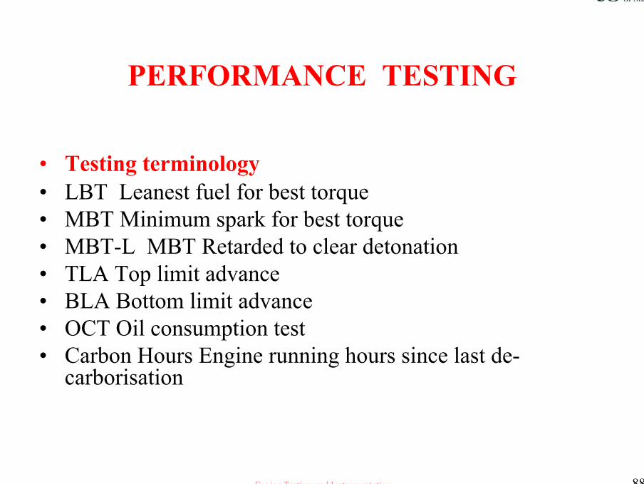
• Testing terminology• LBT Leanest fuel for best torque• MBT Minimum spark for best torque• MBT-L MBT Retarded to clear detonation• TLA Top limit advance• BLA Bottom limit advance• OCT Oil consumption test• Carbon Hours Engine running hours since last de-
carborisation

Engine Testing and Instrumentation 89
PERFORMANCE TESTING
Measurement of mechanical losses
• Indicator diagram• Motoring tests• Morse tests• Willans line
– We will consider the last three
Engine Testing and Instrumentation 90
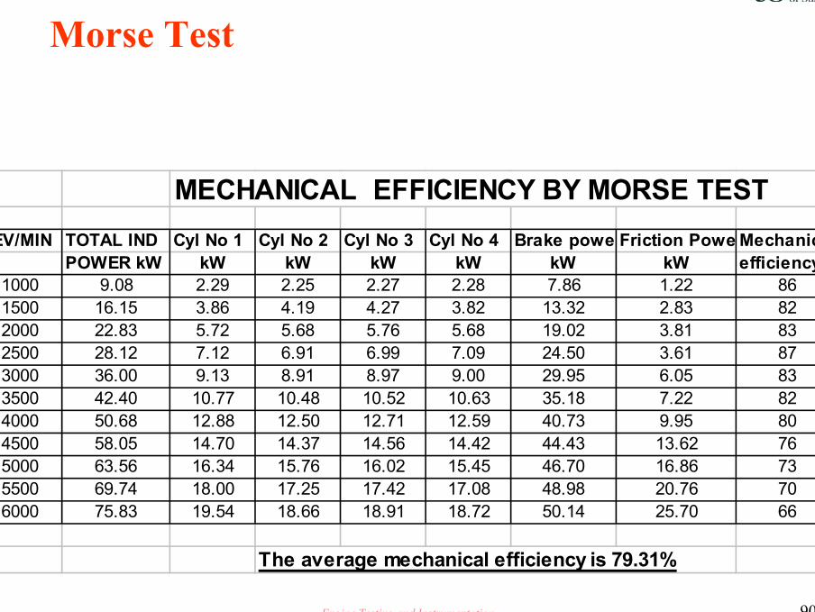
Morse Test
MECHANICAL EFFICIENCY BY MORSE TESTREV/MIN TOTAL IND Cyl No 1 Cyl No 2 Cyl No 3 Cyl No 4 Brake powe Friction Powe Mechanical
POWER kW kW kW kW kW kW kW efficiency %1000 9.08 2.29 2.25 2.27 2.28 7.86 1.22 861500 16.15 3.86 4.19 4.27 3.82 13.32 2.83 822000 22.83 5.72 5.68 5.76 5.68 19.02 3.81 832500 28.12 7.12 6.91 6.99 7.09 24.50 3.61 873000 36.00 9.13 8.91 8.97 9.00 29.95 6.05 833500 42.40 10.77 10.48 10.52 10.63 35.18 7.22 824000 50.68 12.88 12.50 12.71 12.59 40.73 9.95 804500 58.05 14.70 14.37 14.56 14.42 44.43 13.62 765000 63.56 16.34 15.76 16.02 15.45 46.70 16.86 735500 69.74 18.00 17.25 17.42 17.08 48.98 20.76 706000 75.83 19.54 18.66 18.91 18.72 50.14 25.70 66
The average mechanical efficiency is 79.31%

Engine Testing and Instrumentation 91
PERFORMANCE TESTINGThe WILLAN’S Line Method
Applicable mainly for diesel engines
• The curve of fuel consumption rate against torque at constant speeds plots well as a straight line up to 75% of full power.
• Equal increases in fuel give equal increases in power ( combustion efficiency being constant)
• At zero power, all fuel burned is expended in overcoming mechanical losses.
• Extrapolation of the Willan’s line to zero fuel consumption gives a measure of friction losses in the engine

Engine Testing and Instrumentation 92
Engine Testing and Instrumentation 93
Major causes of mechanical failure
• Rubbing or sliding movement
• Vibration induced by the firing strokes of the engine
• Out of balance reciprocating masses

Engine Testing and Instrumentation 94

Engine Testing and Instrumentation 95
Engine Testing and Instrumentation 96
PERFORMANCE TESTING
Diesel - Cetane NumberCetane number is the most important diesel fuel
specification. It is an indication of the extent of ignition delay.
The higher the cetane number the shorter the ignition delay, the smoother the combustion and the cleaner the exhaust
Cold starting is easier the higher the cetane number
Engine Testing and Instrumentation 97
PERFORMANCE TESTING
Calorific value• The calorific value of diesel fuel is lower than that of
gasoline.• Diesel fuel ranges from 40MJ/kg to 43MJ/kg and is a
function of fuel density • The higher the sulphur content the lower the calorific
value, this has a big impact upon new emission regulations

Engine Testing and Instrumentation 98
UNDERSTANDINGDESIGN VALIDATIONTESTING• A SIGNIFICANT WEAPON IN THE
AUTOMOTIVE ENGINEERS ARMOURY

Engine Testing and Instrumentation 99
Design ValidationTesting
• All tests must be thought through• Laboratory experiment• Relevance of the test• test practices• Accuracy of results• Confidence in the test• Cost effectiveness
Engine Testing and Instrumentation 100
Why undertake Design Validation Testing
• It is essential to know prior to starting production that a item or assembly is capable of lasting and resisting accelerated wear within its designed life
• Computer modelling is only part of the answer• This paper out lines the means of determining the type of test
and number of tests required to meet the engines original design objectives

Engine Testing and Instrumentation 101
ENGINE LIFE
• No clear cut engineering definition of engine life exists
• General definition of engine life is the time when key components have to be replaced and the engines performance no longer lies within legislated limits
• Industry definition values for engine life are defined in terms of B10% and B50% this being the time when 10% or 50% of the items under test have failed

Engine Testing and Instrumentation 102
Hazard Failure Rate as a Function of Time‘Bath Tub Curve !!!!’
B10% Contributing to B 50% LifeEarly
Failures Random Failures Wear outFailures
T1 T2 T3Time
Haz
ard
Rat
e
B2 Life

Engine Testing and Instrumentation 103
Relating failure rate to engine life
• In Design levels one and two, initial failure rate reduces to a point where it remains near constant
• This is referred to as the B2 life• Failures are random in nature due to :• Design• Material specification• Production

Engine Testing and Instrumentation 104
Major causes of mechanical failure
• Rubbing or sliding movement
• Vibration induced by the firing strokes of the engine
• Out of balance reciprocating masses

Engine Testing and Instrumentation 105
Confidence in Reliability
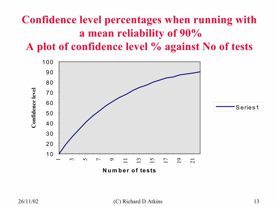
• From the confidence level formulae, it will be seen that to have a reliability of 90% with a confidence level of 90% a total of 22 tests are required
• For the same reliability, one test gives a confidence level of 10% whilst two tests increase this to 19%
• Statistical determination of reliability cannot be made from 1 or 2 tests with any degree of confidence.

Engine Testing and Instrumentation 106
Confidence Level
• Statistical analysis states that for a test series carried out without failure for the specified life the confidence level can be calculated as follows:-
CL = 1 - Rn
CL = Confidence levelR = Reliability
n = Number of tests completed with out failure

Engine Testing and Instrumentation 107
With a reliability of 70%, note the number of tests to give confidence is much reduced
0102030405060708090
100
1 2 3 4 5 6 7 8 9
Number of tests completed with out failure
Conf
iden
ce in
test
s %
Series3
Engine Testing and Instrumentation 10826/11/02 (C) Richard D Atkins 13
10
20
30
40
50
60
70
80
90
1001 3 5 7 9 11 13 15 17 19 21
N u m b er o f tests
Con
fiden
ce le
vel
S eries1
Confidence level percentages when running witha mean reliability of 90%
A plot of confidence level % against No of tests
Engine Testing and Instrumentation 109
Engine Application
• Objective is to establish the probability of a given product reaching its design life which in turn may be dictated by legislation
• Bench tests must replicate and accelerate in service life conditions
• A typical representative test cycle for all engine applications is not possible
• Specialist tests have been developed to test engines over the 4 most important operating conditions

Engine Testing and Instrumentation 110
Major causes of mechanical failure
• Rubbing or sliding movement
• Vibration induced by the firing strokes of the engine
• Out of balance reciprocating masses

Engine Testing and Instrumentation 111
The four most important mechanical test conditions
• Maximum Heat input.Rated Speed and Load
• Thermal Fatigue.Maximum Cyclic Temperature Variation
• Mechanical LoadMaximum Imposed Mechanical Load
• Dynamic LoadMaximum engine speed. no load

Engine Testing and Instrumentation 112
Maximum Heat Input
• Under these conditions , maximum component operating temperatures are attained and components whose durability is largely controlled by the thermal gradient of operation are assessed
• These components include:Piston ( scuff/ring stick etc)Valves and valve seatsInjector nozzleTurbocharger

Engine Testing and Instrumentation 113
Maximum Cyclic Temperature Variation
• These conditions occur when the engine is alternately operated between conditions of maximum and minimum heat input
• To test and assess internal and external components whose durability is determined by their ability to withstand thermal fatigue.
• Components includeCylinder head (Valve bridge area)Cylinder head gasket and fixing boltsPiston,exhaust,turbo charger and fixings

Engine Testing and Instrumentation 114
Maximum Imposed Mechanical Load
• With a turbo charged engine this condition is normally encountered at maximum torque where cylinder pressure is at a maximum and the lower operating speed reduces the extent of inertia relief.
• Components assessed includeSmall end, big end and main bearingsPistonLiner and crankshaft

Engine Testing and Instrumentation 115
Maximum Dynamic Load
• This high inertia condition occurs at the maximum engine speed, normally governor run out speed at no load.
• Maximum stresses are applied toValve train componentsPiston small endMain and big end bearings
Engine Testing and Instrumentation 116
Tests in the developmentof prototype engines
• Manufactures utilise variation of these four test types, testing under severe loading conditions
• Tests of 100 to 200 hours are sufficient to screen new designs ( see ‘Bath Tub Curve’)
• These tests provide sufficient confidence to consider longer term extended engine approval tests

Engine Testing and Instrumentation 117
Durability Duty Cycles
• To cater for the majority of cases and to ensure that components are assessed under the most severe operating conditions, it is usual to specify a test cycle that incorporates one the four extreme conditions we discussed earlier
• The engine build and installation on the test bench should replicate that of the vehicle

Engine Testing and Instrumentation 118
Basic Durability Test Cycle
• Rated load and Speed 20 min• No Load Governor run out 10 min• Maximum Torque 20 min• Idle 10 min
Many manufactures increase the severity of their tests over what is found in normal service. Over speed, over fuelling etc.
Engine Testing and Instrumentation 119
Why increase the severity
• Increasing the severity of tests is of value by reducing the time to complete the tests and thus increasing the confidence level in the analysis of the results
• Early in a new engine programme at least two durability tests of 1000 hours duration should be undertaken

Engine Testing and Instrumentation 120
Caution !!!
• The specification of severe tests requires extreme care and can only normally be achieved by reference to historical data.
• Any one can specify tests of extreme severity which lead to early failure, these cannot be related to normal service and are of dubious worth
• Development on this basis results in the engine being over designed and non competitive
Engine Testing and Instrumentation 121
Design Validation Tests
• Each engine type and application could have its own suit of tests, but we will discuss a few of the more common types of test that used within the industry.
• The objective of this work, is to demonstrate that no major deficiencies are present in the design of the engine

Engine Testing and Instrumentation 122
Duration of Durability tests
• Four aspects to be considered1.Verification that wear will not prevent the expected designed service
being achieved
2.Verification that failure due to mechanical fatigue will not occur
3. Verification that failure due to thermal fatigue will not occur
4. Emission and legislative performance to be maintained within the warranty life of the vehicle

Engine Testing and Instrumentation 123
Life of engineering materials
• The endurance limit for typical engineering materials used in engines is quoted as being between 106 and 107 cycles.
• With a 4 stroke engine a full load cycle is once every 720° crankshaft
• 107 cycles would occur after 166 hours running at a rated speed of 2000 rev/min.
• Operation for 1000 hours would give the following load cycles

Engine Testing and Instrumentation 124
1000 hour test cycles, material strength based
4 x 10⁷ Full speed and load4 x 106 Idle1.6 x 107 Maximum torque1.065 x 107 Governor run out speedA total of 5 x 10⁷ Cycles
This proposed test cycle and duration would demonstrate a high degree of confidence in the durability of the engine with respect to mechanical fatigue
Engine Testing and Instrumentation 125
Thermal Stress
• The maximum thermal stress occurs when a component is operated over the maximum temperature range normally encountered for an extended time
• On an engine this can occur when operating from full load to idle
• The maximum induced stress in thermaly loaded components is significantly higher than the maximum mechanically imposed stresses and thus the number of cycles to failure is lower than the endurance limit
Engine Testing and Instrumentation 126
Cylinder head gasket durability
• The engine is cycled between full load and idle. During the idle mode cold coolant is passed through the engine
• Maximum component in service thermal stress is applied in the minimum time .
• The cylinder head gasket is in fact loaded beyond normal service conditions, due to differential expansion between the cylinder head, crankcase fixing bolts and gasket

Engine Testing and Instrumentation 127
Design Validation Tests
• Rapid Warm Up• The coolant and oil passage ways are fully instrumented
and the rate of temperature rise noted.• Objective, to ensure that the engine reaches operating
temperature in the minimum time.• This is becoming more important with new emission
legislation

Engine Testing and Instrumentation 128
Design Validation Tests
• Valve temperature survey• Why ~ To ensure that valve heads and valve seats do not
exceed the designed temperature limits under operating conditions
• How ~ Engine run at maximum speed and load for 2 hours. Temperature fusible plugs are fitted under the valve seat inserts, and valves of a specific material that changes hardness with temperature rise

Engine Testing and Instrumentation 129
Design Validation Tests
• Piston Slack fit• Why ~ To investigate fatigue of piston skirt and gudgeon
pin boss• How ~ The engine is assembled with increased piston to
bore clearance 100 +- 10Um The engine is run for 180 hours at WOT maximum power rev/min

Engine Testing and Instrumentation 130
Design Validation Tests
• Piston Scuff <> Cold Test• Why ~ To establish piston cylinder bore and piston ring
compatibility under cold starting conditions• How ~ The engine is pre-cooled for 18 hours prior to test.
Six starts are completed at 5°C and six tests are completed at - 25°C

Engine Testing and Instrumentation 131
Design Validation Tests
• Piston Scuff <> Hot Test• Why ~ To confirm piston to bore manufacturing tolerances• How ~ The engine is run at maximum speed and load. The
oil temperature is increased every 10 minutes by 5°C steps until 3.5 hours running completed or the engine has seized up

Engine Testing and Instrumentation 132
Design Validation Tests
• Piston Burn• Why ~ To determine the operating envelope within which
the engine may safely operate• How ~ This is a 100 hour test. The in cylinder temperature
is monitored and the ignition/injection advanced to onset of rapid temperature rise. The condition has to be evaluated for many speeds and loads to build up a safety operating zone
Engine Testing and Instrumentation 133
Design Validation Tests
• Critical speed• Why ~ To ensure that the engine and auxiliary components
do not fail when subjected to continuous running at critical speeds
• How ~ The engine is run at 107 at a predetermined critical speed. There are normally high speed low amplitude and low speed high amplitude critical conditions

Engine Testing and Instrumentation 134
Design Validation Tests
• Valve seat wear• Why ~ To identify potential valve wear problems• How ~ A three stage test.
– 100 hours at 60% maximum power rev/min.Maximum rated power.
– 100 hours at 60% maximum power rev/min. intermediate load.
– 100 hours at maximum torque rev/min. at maximum torque
Engine Testing and Instrumentation 135
Design Validation Tests
• Exhaust manifold crack• Why ~ To determine the crack resistant qualities of
exhaust manifolds and the torque retention properties of exhaust manifold fixing bolts.
• How ~ 200 hour test wherein the engine is run at maximum torque rev/min for 6 minutes, then idled for 4 minutes with maximum spot air cooling to the manifold

Engine Testing and Instrumentation 136
Design Validation Tests
• Thermal shock• Why ~ To ensure that prototype and production cylinder
head gaskets operate satisfactorily when subjected to thermal cycling. To ensure that the bore and cylinder head distortion are held to design limits when subjected to thermal cycling
• How ~ 150 hour test. Engine cycled from full load/speed to idle with temperature delta of 75°C
Engine Testing and Instrumentation 137
Design Validation Tests
• Thermal shock continued• In these tests, the engine is cycled between full load and
idle. During the idle mode, cold coolant/cold air is passed through the engine to rapidly reduce the component temperature. Maximum component in service thermal stress is thus applied in the minimum time. The cylinder head gasket is loaded beyond normal conditions due to the forces of differential expansion. Typically 2000 cycles are run.
Engine Testing and Instrumentation 138
Design Validation Tests
• Mixed Cycle• Why ~ To increase confidence level that prototype and
production engines with all ancillaries will operate reliably for a design life
• How ~ 200 hours full load mixed speed. followed by 200 hours mixed load and speed. The number of repeat tests being dependant upon the degree of confidence in the reliability required.

Engine Testing and Instrumentation 139
Design Validation Tests
• General usage• Why ~ To gain an overall evaluation of the engine and
component performance• How ~ Typically an 8 stage test running from idle to
maximum speed and load. [ Refer to mechanical failure slide ] Each test is normally two tests of 200 hours followed by two tests of 800 hours. N B Failure frequently occur in the first 100 to 200 hours [ B10%]

Engine Testing and Instrumentation 140
Design Validation Tests
• Full Load• Why ~ To ensure that assembly will operate reliably for a
adequate service life• How ~ The engine is cycled between maximum speed and
power up to 500 rev/min over-speed. Typical test duration is 250 hours

Engine Testing and Instrumentation 141
Design Validation Tests
• So what constitutes a good result ?• No critical failure should occur• Performance loss to be less than 5%• Oil consumption within design limits• Blow by should show no increase• Minimal wear on major parts• Components to be in good condition• Specific fuel consumption not to increase by more than 5%

Engine Testing and Instrumentation 142
What constitutes a good test result
• At completion, the engine should be in a good condition and perform as specified
• No critical failure should occur in the test
• Performance loss to be less than 5%
• Oil consumption within design targets
• Blow-by should show no increase
• Minimal wear on major parts
• Good component condition
• Specific fuel consumption should not increase by more than 5%

Engine Testing and Instrumentation 143
Design Validation Tests and the Development Engineer
• What does design validation testing give the engineer• A means of comparing differing engine build
specifications , one with another
• An aid to engine development from design level one to production sign off
• A production quality tool
Engine Testing and Instrumentation 144
BASIC MEASUREMENTS
Engine Instrumentation• Air cleaner differential pressure• Boost ( if applicable) centre of inlet manifold• EGR Vacuum/pressure• EBP 75mm+/-10mm down stream of mating flange• Fuel supply pressure, +ve.. : -ve..• Intake manifold vacuum centre of manifold• Oil Pressure ; Engine gallery take off position• Temperature Thermocouples always as close to outlet/inlet
as possible in a position where flow is unrestricted• Fuel temperature, measure as close to the measuring head
as possible

Engine Testing and Instrumentation 145
BASIC MEASUREMENTS
Engine Instrumentation• ACCURACY• Fuel flow +/-1% of reading• Pressure +/- 0.5% of full scale• Speed +/- 5 rev/min throughout range• Injection/spark +/- 0.5° of reading• Temperature +/- 1.5 °C up to 150°C• Temperature +/- 3.5°C between 150° and 1000°• Torque +/- 0.5Nm or +/-1% of full scale• Emissions +/- 3% of full scale

Engine Testing and Instrumentation 146
BASIC REQUIREMENTS
CALIBRATIONInstruments and test equipment must be calibrated at test facility specified calibration intervals and must have current laboratory calibration records.
Full tractability of all calibration records is a prerequisite of all professional engine testlaboratories
Engine Testing and Instrumentation 147
WHAT READING ARE IMPORTANT
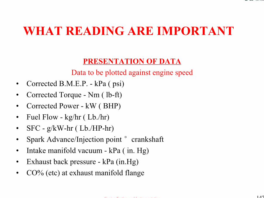
PRESENTATION OF DATAData to be plotted against engine speed
• Corrected B.M.E.P. - kPa ( psi)• Corrected Torque - Nm ( lb-ft)• Corrected Power - kW ( BHP)• Fuel Flow - kg/hr ( Lb./hr)• SFC - g/kW-hr ( Lb./HP-hr)• Spark Advance/Injection point °crankshaft• Intake manifold vacuum - kPa ( in. Hg)• Exhaust back pressure - kPa (in.Hg)• CO% (etc) at exhaust manifold flange

Engine Testing and Instrumentation 148
Design Validation Tests
• TAKING READINGS• Allow engine to stabilise at each set point• Oil and coolant temperatures to be held constant to pre-
determined limits• Allow a minimum of 5 minutes between each set of
readings• Instigate fuel and emission readings at the end of the
stabilisation period

Engine Testing and Instrumentation 149
CONFIDENCE
• NEED TO REPEAT ALL ENGINE TESTS• In order to have statistical confidence in the results of any
performance test, it is necessary to the repeat the test at least twice, if possible three times.

Engine Testing and Instrumentation 150
DESIGN LEVEL ONE STANDARD DVT TESTS
Full load cycle test
Thermal shock test
Exhaust manifold crack tests
Valve wear cycle tests
General usage cycle test
Critical speed tests

Engine Testing and Instrumentation 151
DESIGN LEVEL TWOSTANDARD DVT TESTS
TESTS AS PER DESIGN LEVEL ONE
• THE NUMBER OF TESTS AND THE DURATION OF EACH TEST INCREASED.
• IN FIELD DURABILITY TESTS START

Engine Testing and Instrumentation 152
OFF TOOL VALIDATIONCOST SAVINGS
Intelligent interpretation of tests
Ensure that all tests produced to the highest standards
Produce significant savings in the period between design concept and production sign off
Engine Testing and Instrumentation 153
VALUE FOR MONEY
To achieve the maximum value from any DVT work, the measurement and assessment of critical components pre and post test is a prerequisite.
This assessment would include the measurement of wear, rating of component condition and analysis of fluids and lubricant.
This data enables the engineer to undertake predictive analysis of wear rates [ Re Bath Tub !] and thus to increase his confidence level in the validity of the test results and thus reduce the total number of tests to be undertaken

Engine Testing and Instrumentation 154
OIL ANALYSIS
• To gain information with regard to the integrity of the engine under test, it is recommend that 125 cc samples of engine oil are taken at agreed intervals and the following analysis performed :
• Fuel Dilution Reference ASTM D 3524• Soot Content Reference IFP 303/03• Viscosity Reference ASTM D 445 (N40°C
100°C)• Metal Content Reference ASTM D 4951/5185• Sulphur Content Reference IP 244/ICP• Base No. (Acidity) Reference ASTM D 664/2896.

Engine Testing and Instrumentation 155
Engine Application
• Objective is to establish the probability of a given product reaching its design life which in turn may be dictated by legislation
• Bench tests must replicate and accelerate in service life conditions
• A typical representative test cycle for all engine applications is not possible
• Specialist tests have been developed to test engines over the 4 most important operating conditions

Engine Testing and Instrumentation 156
WHAT NOW !!
• We understand why we have to test, but prior to discussing types of tests, let us for a moment consider how one can get the maximum value out of each test

Engine Testing and Instrumentation 157
Your place in the equation
• The importance of the technicians place within the automotive industry cannot be too highly stressed.
• It is the fine attention too detail that makes the difference between a successful new model and a dead duck.
• How can this be ?

Engine Testing and Instrumentation 158
The consequence of poor attention to detail
• Imagine if you will this scenario• A Saudi Prince has ordered a series of Vehicles ~ he
tells his chums at the oasis and the Polo Club• The vehicles are delivered• The Prince shows them to his chums, who point out the oil
leaks. The leaks were noticed on test but not reported !!• The Prince has lost face ~ The company has lost many
potential sales

Engine Testing and Instrumentation 159
Close attention to detail the ‘Professional Technician’
• The same scenario• There were oil leaks on test, but these were noted and the
company were able to rectify prior to production sign off• The Prince receives the units• He show it to his chums, NO OIL LEAKS• They are impressed• Additional sales are made• A simplistic story BUT valid

Engine Testing and Instrumentation 160
Your responsibility
• Accuracy and Attention to detail must become a way of life for you
• You are a professional and are on the ladder to becoming a chartered engineer
• You must do all in your power to ensure that the results you produce are correct ~ this is not as simple as it sounds