euramet key comparison euramet.l-k5.2016 calibration of...
TRANSCRIPT
EURAMET L-K5.2016 Calibration of step gauge Technical protocol
CCL-15-13-EURAMET.L-K5-2016 technical protocol v1 7.docx Pg. 1/26
EURAMET Key Comparison
EURAMET.L-K5.2016
Calibration of 1-D CMM artefacts: Step Gauges
(EURAMET project 1365)
Technical protocol
National Physical Laboratory
UK
Teddington
March 2016
EURAMET L-K5.2016 Calibration of step gauges Technical protocol
Contents
1 Document control ...................................................................................................................................3
2 Introduction ..........................................................................................................................................3
3 Preparation of the comparison documents ..........................................................................................4
4 Organization ..........................................................................................................................................5
4.1 Participants ...................................................................................................................................5
4.2 Schedule ........................................................................................................................................8
4.3 Receipt, transportation, insurance, costs .................................................................................. 11
5 Artefacts ............................................................................................................................................. 12
5.1 Description of artefacts.............................................................................................................. 12
6 Measuring instructions ...................................................................................................................... 17
6.1 Mounting the artefact ................................................................................................................ 17
6.2 Handling the artefact ................................................................................................................. 17
6.2.1 General handling ................................................................................................................ 17
6.2.2 Cleaning .............................................................................................................................. 17
6.2.3 Temperature measurement of the artefact ...................................................................... 17
6.2.4 Storage ............................................................................................................................... 17
6.3 Traceability ................................................................................................................................. 17
6.4 Measurands ............................................................................................................................... 17
6.5 Measurement instructions ......................................................................................................... 18
6.6 Measurement conditions ........................................................................................................... 18
6.7 Measurement uncertainty ......................................................................................................... 18
7 Reporting of results ............................................................................................................................ 19
7.1 Results and standard uncertainties as reported by participants ............................................... 19
8 Analysis of results .............................................................................................................................. 20
8.1 Calculation of the KCRV ............................................................................................................. 20
8.2 Artefact instability ...................................................................................................................... 20
8.3 Correlation between laboratories.............................................................................................. 20
9 Non-NMI laboratory Participation ..................................................................................................... 21
9.1 Zeiss ............................................................................................................................................ 21
Appendix A – Reception of Standards ....................................................................................................... 22
Appendix B – Results Report Form ............................................................................................................ 23
Appendix C –– Description of the measurement instrument .................................................................... 27
EURAMET L-K5.2016 Calibration of step gauges Technical protocol
1 Document control
V1.0 12 May 2015 Initial collection of data and outline of comparison V1.2 9 July 2015 Finalised list of participants, details about artefacts V1.3 24 August 2015 Finalised artefact details V1.4 22 September 2015 Minor corrections V1.5 11 December 2015 Finalised schedule and added final participants. V1.6 31 March 2016 Added two informal participants. V1.7 25 July 2016 Struck out INMETRO following their request to withdraw. Updated CTE uncertainty for 1020 mm artefact to match calibrated value
2 Introduction
The metrological equivalence of national measurement standards will be determined by a set of key comparisons chosen and organised by the Consultative Committees of the CIPM working closely with the Regional Metrology Organizations (RMOs). Calibration and Measurement Capabilities (CMCs), which are traceable to national measurement standards, are supported by evidence primarily coming from the results of key and supplementary comparisons, together with the operation of approved and mutually accepted quality systems.
To date, several key comparisons on 1D CMM calibration artefacts have been performed:
EUROMET.L-K5.PREV : 1996 to 1998 : Spain, Italy, Switzerland, Netherlands, UK, Germany, Sweden
CCL-K5 : 1999 to 2002 : Spain, Mexico, South Africa, Italy, S. Korea, Switzerland, China, USA, Australia, Japan, Canada, Germany, Russian Federation
EUROMET.L-K5.2004 : 2004 to 2007 : Austria, Spain, Mexico, Czech Republic, Denmark, Poland, Romania, Brazil, Italy, France, Finland, Hungary, Australia, UK, Canada, Ireland, Sweden, Russian Federation, Netherlands
APMP.L-K5.2006 : 2005 to 2007 : Chinese Taipei, Brazil, S. Korea, Switzerland, New Zealand, China, Thailand, USA, Australia, Japan, India, Indonesia, Hong Kong)
APMP.L-K5.2006.1 : 2012 to 2013 : Japan, India
In 2003 the CCL instigated the process of inter-RMO participation in RMO key comparisons. This is designed to reduce the workload of CCL member laboratories in comparison subjects where there are too few participants to warrant the use of the classical style of comparison (CCL comparison followed by an RMO comparison in each of the regions) in which CCL member laboratories have to participate twice.
At its meeting in 2003, the APMP Technical Committee Length (TCL) decided that a new key comparison on step gauge measurements would be carried out and the resulting comparison, APMP.L-K5.2006 was undertaken, involving 13 NMIs; however several laboratories had anomalous results in that comparison. So at the 2013 APMP meeting, the APMP TCL decided to organize a follow-up comparison as a corrective action for NMIs reporting anomalous results in the 2006 comparison. A step gauge manufactured by Mitutoyo was chosen as the artefact for this comparison because most NMIs in the APMP region are familiar with Mitutoyo step gauges. This follow-up comparison, APMP.L-K5.2014, is underway and involves the following nations: S. Korea, Thailand, Indonesia, Australia, China.
Similarly, noting that nearly 10 years had elapsed since the previous European K5 comparison, EURAMET TC-L decided to organize the next K5 comparison to start in 2016 and the CCL meeting in 2013 agreed that this comparison would be operated as an inter-RMO key comparison with NPL as the pilot laboratory. Two NMIs from the APMP region will take place in the EURAMET comparison to form the necessary link to their previous comparison.
EURAMET L-K5.2016 Calibration of step gauges Technical protocol
3 Preparation of the comparison documents
This protocol document has been prepared by the pilot, Tim Coveney, from the pilot laboratory NPL (UK).
The procedures outlined in this document cover the technical procedure to be followed during measurement of the step gauge artefacts. The procedure follows the guidelines established by the BIPM1 and subsequently revised by the CIPM through the JCRB as well as detailed guidance document issued by the CCL’s Working Group on the MRA. These include the following documents:
CIPM MRA-D-052 Measurement comparisons in the CIPM MRA
CCL-WG/-MRA-GD-13 Running of MRA comparisons in length metrology and monitoring their impact on CMCs
CCL-WG/-MRA-GD-24 CCL comparison scheme
CCL-WG/-MRA-GD-3.15 Technical protocol template
The final report of this comparison will be prepared according to the following guidance documents:
Publication of a Final Report in Metrologia’s Technical Supplement6
CCL-WG/-MRA-GD-37 Guide to preparation of Key Comparison Reports in Dimensional Metrology
CCL-WG/-MRA-GD-3.28 Report template
1 T.J. Quinn, Guidelines for key comparisons carried out by Consultative Committees, BIPM, Paris
2 http://www.bipm.org/utils/common/documents/CIPM-MRA/CIPM-MRA-D-05.pdf
3 http://www.bipm.org/wg/CCL/CCL-WG/Allowed/General_CCL-WG_docs/CCL-WG-MRA-GD-1-v6.8.doc
4 http://www.bipm.org/wg/CCL/CCL-WG/Allowed/General_CCL-WG_docs/CCL-WG-MRA-GD-2.pdf
5 http://www.bipm.org/wg/CCL/CCL-WG/Allowed/General_CCL-WG_docs/CCL-WG-MRA-GD-3.1-KC-technical-
protocol-template.doc 6 http://www.bipm.org/utils/common/documents/CIPM-MRA/MET-Technical-Supplement.docx
7 http://www.bipm.org/wg/CCL/CCL-WG/Allowed/General_CCL-WG_docs/CCL-WG-MRA-GD-3-v1.3.doc
8 http://www.bipm.org/wg/CCL/CCL-WG/Allowed/General_CCL-WG_docs/CCL-WG-MRA-GD-3.2-KC-report-
template.doc
EURAMET L-K5.2016 Calibration of step gauges Technical protocol
4 Organization
4.1 Participants
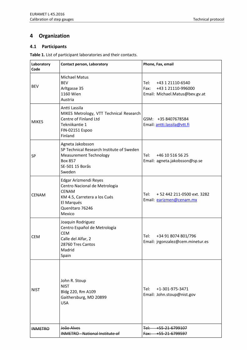
Table 1. List of participant laboratories and their contacts.
Laboratory Code
Contact person, Laboratory Phone, Fax, email
BEV
Michael Matus BEV Arltgasse 35 1160 Wien Austria
Tel: +43 1 21110-6540 Fax: +43 1 21110-996000 Email: [email protected]
MIKES
Antti Lassila MIKES Metrology, VTT Technical Research Centre of Finland Ltd Tekniikantie 1 FIN-02151 Espoo Finland
GSM: +35 8407678584 Email: [email protected]
SP
Agneta Jakobsson SP Technical Research Institute of Sweden Measurement Technology Box 857 SE-501 15 Borås Sweden
Tel: +46 10 516 56 25 Email: [email protected]
CENAM
Edgar Arizmendi Reyes Centro Nacional de Metrologia CENAM KM 4.5, Carretera a los Cués El Marqués Querétaro 76246 Mexico
Tel: + 52 442 211-0500 ext. 3282 Email: [email protected]
CEM
Joaquin Rodriguez 1. Centro Español de Metrología 2. CEM
Calle del Alfar, 2 28760 Tres Cantos Madrid Spain
Tel: +34 91 8074 801/796 Email: [email protected]
NIST
John R. Stoup NIST Bldg 220, Rm A109 Gaithersburg, MD 20899 USA
Tel: +1-301-975-3471 Email: [email protected]
INMETRO João Alves INMETRO - National Institute of
Tel: +55-21-6799107 Fax: +55-21-6799597
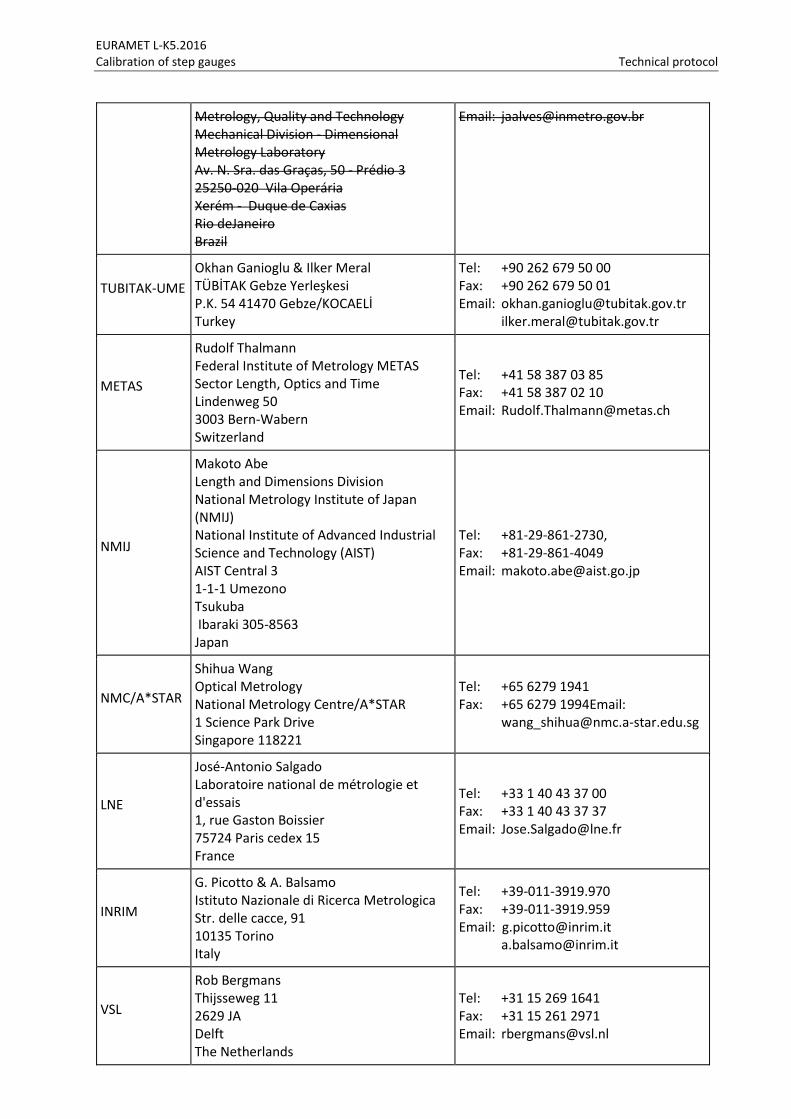
EURAMET L-K5.2016 Calibration of step gauges Technical protocol
Metrology, Quality and Technology Mechanical Division - Dimensional Metrology Laboratory Av. N. Sra. das Graças, 50 - Prédio 3 25250-020 Vila Operária Xerém - Duque de Caxias Rio deJaneiro Brazil
Email: [email protected]
TUBITAK-UME
Okhan Ganioglu & Ilker Meral TÜBİTAK Gebze Yerleşkesi P.K. 54 41470 Gebze/KOCAELİ Turkey
Tel: +90 262 679 50 00 Fax: +90 262 679 50 01 Email: [email protected] [email protected]
METAS
Rudolf Thalmann Federal Institute of Metrology METAS Sector Length, Optics and Time Lindenweg 50 3003 Bern-Wabern Switzerland
Tel: +41 58 387 03 85 Fax: +41 58 387 02 10 Email: [email protected]
NMIJ
Makoto Abe Length and Dimensions Division National Metrology Institute of Japan (NMIJ) National Institute of Advanced Industrial Science and Technology (AIST) AIST Central 3 1-1-1 Umezono Tsukuba Ibaraki 305-8563 Japan
Tel: +81-29-861-2730, Fax: +81-29-861-4049 Email: [email protected]
NMC/A*STAR
Shihua Wang Optical Metrology National Metrology Centre/A*STAR 1 Science Park Drive Singapore 118221
Tel: +65 6279 1941 Fax: +65 6279 1994Email: [email protected]
LNE
José-Antonio Salgado Laboratoire national de métrologie et d'essais 1, rue Gaston Boissier 75724 Paris cedex 15 France
Tel: +33 1 40 43 37 00 Fax: +33 1 40 43 37 37 Email: [email protected]
INRIM
G. Picotto & A. Balsamo Istituto Nazionale di Ricerca Metrologica Str. delle cacce, 91 10135 Torino Italy
Tel: +39-011-3919.970 Fax: +39-011-3919.959 Email: [email protected] [email protected]
VSL
Rob Bergmans Thijsseweg 11 2629 JA Delft The Netherlands
Tel: +31 15 269 1641 Fax: +31 15 261 2971 Email: [email protected]
EURAMET L-K5.2016 Calibration of step gauges Technical protocol
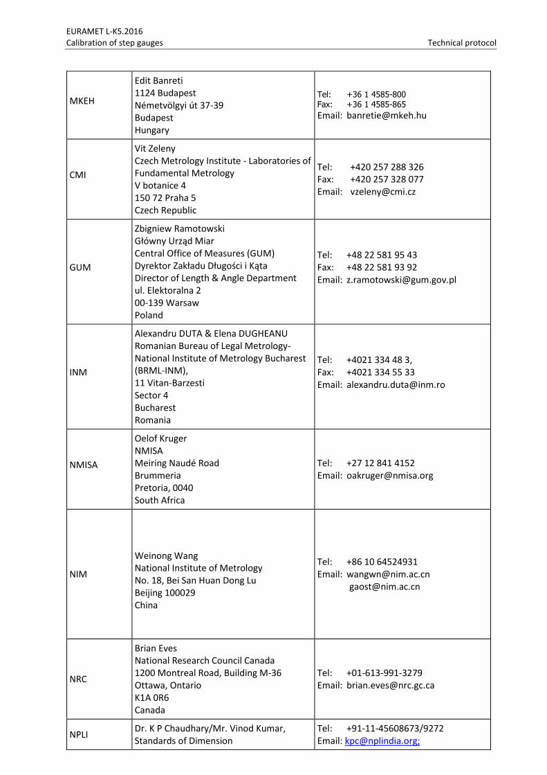
MKEH
Edit Banreti 1124 Budapest Németvölgyi út 37-39 Budapest Hungary
Tel: +36 1 4585-800 Fax: +36 1 4585-865
Email: [email protected]
CMI
Vit Zeleny Czech Metrology Institute - Laboratories of Fundamental Metrology V botanice 4 150 72 Praha 5 Czech Republic
Tel: +420 257 288 326 Fax: +420 257 328 077 Email: [email protected]
GUM
Zbigniew Ramotowski Główny Urząd Miar Central Office of Measures (GUM) Dyrektor Zakładu Długości i Kąta Director of Length & Angle Department ul. Elektoralna 2 00-139 Warsaw Poland
Tel: +48 22 581 95 43 Fax: +48 22 581 93 92 Email: [email protected]
INM
Alexandru DUTA & Elena DUGHEANU Romanian Bureau of Legal Metrology- National Institute of Metrology Bucharest (BRML-INM), 11 Vitan-Barzesti Sector 4 Bucharest Romania
Tel: +4021 334 48 3, Fax: +4021 334 55 33 Email: [email protected]
NMISA
Oelof Kruger NMISA Meiring Naudé Road Brummeria Pretoria, 0040 South Africa
Tel: +27 12 841 4152 Email: [email protected]
NIM
Weinong Wang National Institute of Metrology No. 18, Bei San Huan Dong Lu Beijing 100029 China
Tel: +86 10 64524931 Email: [email protected] [email protected]
NRC
Brian Eves National Research Council Canada 1200 Montreal Road, Building M-36 Ottawa, Ontario K1A 0R6 Canada
Tel: +01-613-991-3279 Email: [email protected]
NPLI Dr. K P Chaudhary/Mr. Vinod Kumar, Standards of Dimension
Tel: +91-11-45608673/9272 Email: [email protected];
EURAMET L-K5.2016 Calibration of step gauges Technical protocol
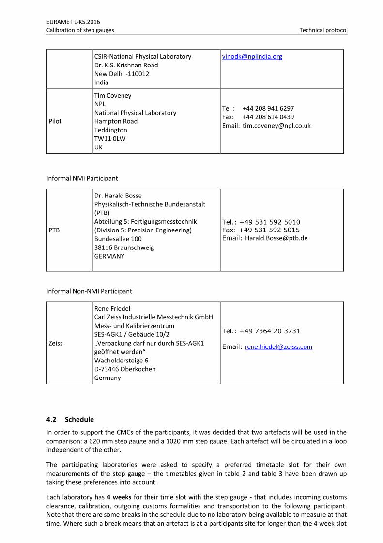
CSIR-National Physical Laboratory Dr. K.S. Krishnan Road New Delhi -110012 India
Pilot
Tim Coveney NPL National Physical Laboratory Hampton Road Teddington TW11 0LW UK
Tel : +44 208 941 6297 Fax: +44 208 614 0439 Email: [email protected]
Informal NMI Participant
PTB
Dr. Harald Bosse Physikalisch-Technische Bundesanstalt (PTB) Abteilung 5: Fertigungsmesstechnik (Division 5: Precision Engineering) Bundesallee 100 38116 Braunschweig GERMANY
Tel.: +49 531 592 5010
Fax: +49 531 592 5015
Email: [email protected]
Informal Non-NMI Participant
Zeiss
Rene Friedel Carl Zeiss Industrielle Messtechnik GmbH Mess- und Kalibrierzentrum SES-AGK1 / Gebäude 10/2 „Verpackung darf nur durch SES-AGK1 geöffnet werden“ Wacholdersteige 6 D-73446 Oberkochen Germany
Tel.: +49 7364 20 3731
Email: [email protected]
4.2 Schedule
In order to support the CMCs of the participants, it was decided that two artefacts will be used in the comparison: a 620 mm step gauge and a 1020 mm step gauge. Each artefact will be circulated in a loop independent of the other.
The participating laboratories were asked to specify a preferred timetable slot for their own measurements of the step gauge – the timetables given in table 2 and table 3 have been drawn up taking these preferences into account.
Each laboratory has 4 weeks for their time slot with the step gauge - that includes incoming customs clearance, calibration, outgoing customs formalities and transportation to the following participant. Note that there are some breaks in the schedule due to no laboratory being available to measure at that time. Where such a break means that an artefact is at a participants site for longer than the 4 week slot

EURAMET L-K5.2016 Calibration of step gauges Technical protocol
it is expected that the participant shall not use this additional time for further measurement in order to maintain the fairness of the comparison.
Key comparisons are designed to test the CMCs of participants. According to document CIPM MRA-D-04 Calibration and Measurement Capabilities in the context of the CIPM MRA:
“A CMC is a calibration and measurement capability available to customers under normal conditions”
“Under a CMC, the measurement or calibration should be:
- performed according to a documented procedure and have an established uncertainty budget under the management system of the NMI or the accredited laboratory;
- performed on a regular basis (including on demand or scheduled for convenience at specific times in the year); and
- available to all clients.”
Therefore, it should be possible to perform the measurements of this comparison as if they were being performed for a customer, according to a pre-agreed timetable (barring unforeseen equipment failures).
With its confirmation to participate, each laboratory is obliged to perform the measurements in the allocated period and to allow enough time in advance for transportation so that the following participant receives them in time. It guarantees that the artefact will be shipped to the country of the next participant in the 4 weeks after receiving the gauge.
If a laboratory has technical problems to perform the measurements or customs clearance takes too long, the laboratory has to contact the pilot laboratory as soon as possible and, according to whatever it decides, it might eventually be obliged to send the standards directly to the next participant before completing the measurements or even without doing any measurements.
The two artefacts will be circulated in two independent loops, both starting and ending at the pilot laboratory. For the longer of the two loops, there will be intermediate measurements by the pilot laboratory in order to confirm artefact stability.
The starting date for each participant is the date by which they should have received the artefact from the previous participant. Each participant should ensure that the artefact is received by the next participant on or before their starting date.
!
EURAMET L-K5.2016 Calibration of step gauges Technical protocol
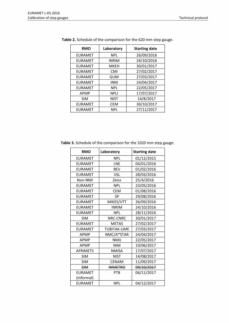
Table 2. Schedule of the comparison for the 620 mm step gauge.
RMO Laboratory Starting date
EURAMET NPL 26/09/2016
EURAMET INRIM 24/10/2016
EURAMET MKEH 30/01/2017
EURAMET CMI 27/02/2017
EURAMET GUM 27/03/2017
EURAMET INM 24/04/2017
EURAMET NPL 22/05/2017
APMP NPLI 17/07/2017
SIM NIST 14/8/2017
EURAMET CEM 30/10/2017
EURAMET NPL 27/11/2017
Table 3. Schedule of the comparison for the 1020 mm step gauge.
RMO Laboratory Starting date
EURAMET NPL 01/12/2015
EURAMET LNE 04/01/2016
EURAMET BEV 01/02/2016
EURAMET VSL 28/03/2016
Non-NMI Zeiss 25/4/2016
EURAMET NPL 23/05/2016
EURAMET CEM 01/08/2016
EURAMET SP 29/08/2016
EURAMET MIKES/VTT 26/09/2016
EURAMET INRIM 24/10/2016
EURAMET NPL 28/11/2016
SIM NRC-CNRC 30/01/2017
EURAMET METAS 27/02/2017
EURAMET TUBITAK-UME 27/03/2017
APMP NMC/A*STAR 24/04/2017
APMP NMIJ 22/05/2017
APMP NIM 19/06/2017
AFRIMETS NMISA 17/07/2017
SIM NIST 14/08/2017
SIM CENAM 11/09/2017
SIM INMETRO 09/10/2017
EURAMET (Informal)
PTB 06/11/2017
EURAMET NPL 04/12/2017
EURAMET L-K5.2016 Calibration of step gauges Technical protocol
Receipt, transportation, insurance, costs The artefact shall be examined immediately after receipt. The condition of the artefact shall be noted (a photograph or a drawing should be made if the artefact is damaged) and all discrepancies shall communicated to the pilot laboratory. The fax form in Appendix A should be used for this purpose.
The artefact should only be handled by authorized persons and stored in a proper way in order to prevent damage.
The artefact shall be examined before dispatch and any change in condition during the measurement shall be communicated to the pilot laboratory.
Please inform the pilot laboratory and the next laboratory via fax or e-mail when the artefact is about to be sent to the next recipient.
The artefact shall be packed according to the instructions in the package. Ensure that the content of the package is complete before shipment. Always use the original packaging.
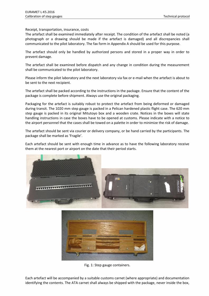
Packaging for the artefact is suitably robust to protect the artefact from being deformed or damaged during transit. The 1020 mm step gauge is packed in a Pelican hardened plastic flight case. The 620 mm step gauge is packed in its original Mitutoyo box and a wooden crate. Notices in the boxes will state handling instructions in case the boxes have to be opened at customs. Please indicate with a notice to the airport personnel that the cases shall be towed on a palette in order to minimize the risk of damage.
The artefact should be sent via courier or delivery company, or be hand carried by the participants. The package shall be marked as ‘Fragile’.
Each artefact should be sent with enough time in advance as to have the following laboratory receive them at the nearest port or airport on the date that their period starts.
Fig. 1: Step gauge containers.
Each artefact will be accompanied by a suitable customs carnet (where appropriate) and documentation identifying the contents. The ATA carnet shall always be shipped with the package, never inside the box,
EURAMET L-K5.2016 Calibration of step gauges Technical protocol
but apart. Please be certain, that when receiving the package, you also receive the carnet! Every time the carnet is used, it is stamped TWICE – on exit from one country and on entry into the next. Please examine the carnet and assure that the transportation company used has arranged for correct stamping of the carnet. Failure to ensure both stamps (exit, entry) subjects the carnet holder to a penalty.
Transportation and insurance is each laboratory’s responsibility and cost. Each participating laboratory covers the costs for its own measurements, transportation and any customs charges. Each laboratory is responsible for any damage of the artefact from the point of receipt at their site until the artefact is signed for on receipt at the next laboratory. The insurance value of each artefact is $10,000. The overall costs for the organization, initial and interim measurements and the processing of results are covered by the pilot laboratory however any damage to or loss of either artefact must be paid for by the responsible participant. By their confirmation of participation, each laboratory agrees to be bound by these requirements.
5 Artefacts
5.1 Description of artefacts
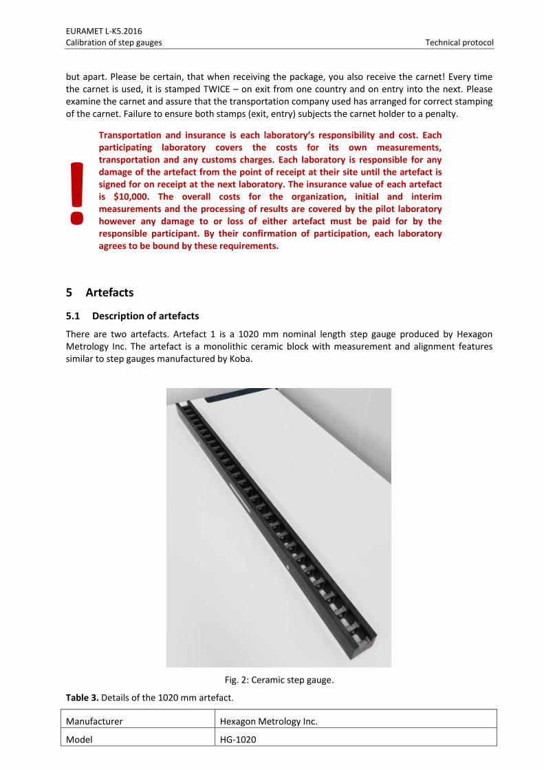
There are two artefacts. Artefact 1 is a 1020 mm nominal length step gauge produced by Hexagon Metrology Inc. The artefact is a monolithic ceramic block with measurement and alignment features similar to step gauges manufactured by Koba.
Fig. 2: Ceramic step gauge.
Table 3. Details of the 1020 mm artefact.
Manufacturer Hexagon Metrology Inc.
Model HG-1020
!
EURAMET L-K5.2016 Calibration of step gauges Technical protocol
Serial Number GC14385
Material Ceramic
Weight 5.4 kg
Thermal expansion coefficient 2.3 10-6 K-1 (calibrated value)
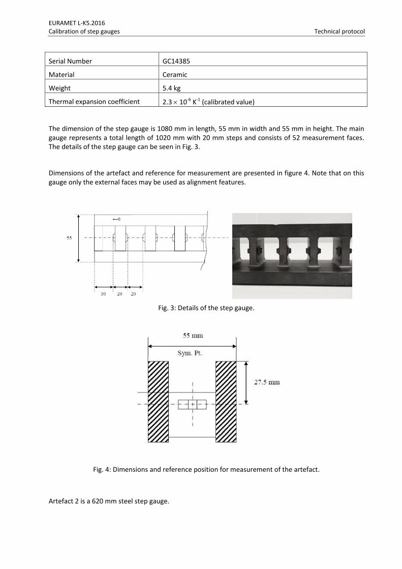
The dimension of the step gauge is 1080 mm in length, 55 mm in width and 55 mm in height. The main gauge represents a total length of 1020 mm with 20 mm steps and consists of 52 measurement faces. The details of the step gauge can be seen in Fig. 3.
Dimensions of the artefact and reference for measurement are presented in figure 4. Note that on this gauge only the external faces may be used as alignment features.
Fig. 3: Details of the step gauge.
Fig. 4: Dimensions and reference position for measurement of the artefact.
Artefact 2 is a 620 mm steel step gauge.
EURAMET L-K5.2016 Calibration of step gauges Technical protocol
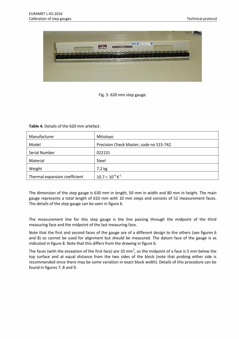
Fig. 5: 620 mm step gauge.
Table 4. Details of the 620 mm artefact.
Manufacturer Mitutoyo
Model Precision Check Master, code no 515-742
Serial Number 022131
Material Steel
Weight 7.2 kg
Thermal expansion coefficient 10.7 10-6 K-1
The dimension of the step gauge is 630 mm in length, 50 mm in width and 80 mm in height. The main gauge represents a total length of 610 mm with 10 mm steps and consists of 52 measurement faces. The details of the step gauge can be seen in figure 6.
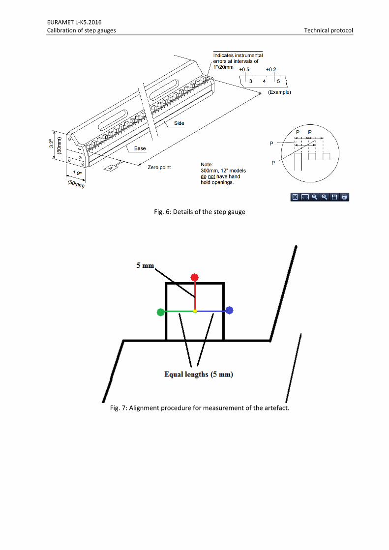
The measurement line for this step gauge is the line passing through the midpoint of the third measuring face and the midpoint of the last measuring face.
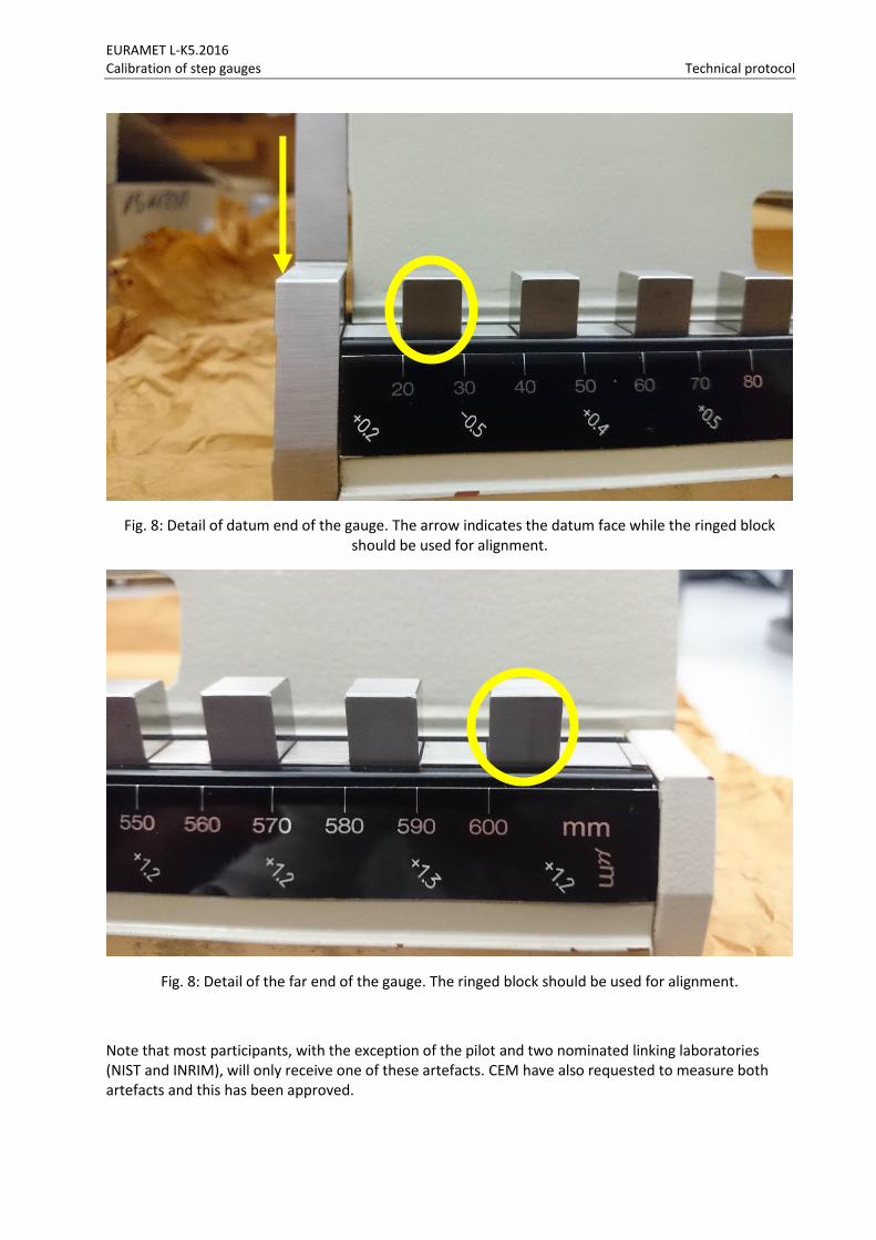
Note that the first and second faces of the gauge are of a different design to the others (see figures 6 and 8) so cannot be used for alignment but should be measured. The datum face of the gauge is as indicated in figure 8. Note that this differs from the drawing in figure 6.
The faces (with the exception of the first face) are 10 mm2, so the midpoint of a face is 5 mm below the top surface and at equal distance from the two sides of the block (note that probing either side is recommended since there may be some variation in exact block width). Details of this procedure can be found in figures 7, 8 and 9.
EURAMET L-K5.2016 Calibration of step gauges Technical protocol
Fig. 6: Details of the step gauge
Fig. 7: Alignment procedure for measurement of the artefact.
EURAMET L-K5.2016 Calibration of step gauges Technical protocol
Fig. 8: Detail of datum end of the gauge. The arrow indicates the datum face while the ringed block should be used for alignment.
Fig. 8: Detail of the far end of the gauge. The ringed block should be used for alignment.
Note that most participants, with the exception of the pilot and two nominated linking laboratories (NIST and INRIM), will only receive one of these artefacts. CEM have also requested to measure both artefacts and this has been approved.
EURAMET L-K5.2016 Calibration of step gauges Technical protocol
6 Measuring instructions
6.1 Mounting the artefact
The artefact in each circulation loop will be shipped without any special mounting fixtures (see section 4.3 for details on transport packaging). Within EURAMET.L-K5-2016 it is recommended to support the artefact at the Bessel points. For this, the positions of the Bessel points are indicated at the sides of the gauge.
6.2 Handling the artefact
6.2.1 General handling
Open the transport container carefully. Use gloves to handle the step gauge and never touch the measuring faces of step gauge with bare fingers. Before shipping for transportation, cover the step gauge with oiled paper included in the case.
6.2.2 Cleaning
The gauge should be cleaned of dust particles using dry, clean air or other clean gases. The measurement surfaces should be cleaned using Ethanol. No other cleaning techniques are permitted.
6.2.3 Temperature measurement of the artefact
The measurement results have to be appropriately corrected to the reference temperature of 20 °C using the values of the thermal expansion coefficient provided. See section 6.6.
6.2.4 Storage
Use original transportation container to avoid dust deposits. Always try to keep the artefact under good measuring room conditions, i.e. within the room, where they get calibrated.
6.3 Traceability
The goal of this EURAMET comparison is to demonstrate the equivalence of routine calibration service for step gauge measurements offered by NMIs/DIs to clients, as listed by them (or soon to be listed) in Appendix C of the BIPM Mutual Recognition Agreement (MRA). To this end, participants in this comparison agree to use the same apparatus and methods as routinely applied when calibrating artefacts for clients. Participants are free to tune and operate their systems to best-measurement performance and to take any extra measurements needed to produce a best measurement result, provided that these extra efforts would also be available to a client if requested.
Length measurements should be traceable to the latest realisation of the metre as set out in the current “Mise en Pratique”. Temperature measurements should be made using the International Temperature Scale of 1990 (ITS-90).
6.4 Measurands
The measurands of the step gauge are the distances of the centres of the front and back faces of the individual gauges of the step-gauge with respect to the centre of the front face of the first gauge. The measurements should be carried out using the measurement lines laid out in section 5.1. The thermal expansion coefficient indicated for the artefact should be used by Laboratories when measuring the artefact. Laboratories should report the temperatures at which the length measurements were made. Laboratories should only measure the artefact at a temperature close to 20 °C.
EURAMET L-K5.2016 Calibration of step gauges Technical protocol
Where an assessment of individual faces flatness or parallelism is part of a laboratory’s standard service this should be carried out and the results reported to the pilot.
6.5 Measurement instructions
The participants are free to choose their own method of measurement. However, under the assumption that the value of the measurand is a true property of the material measure of length, only one result for a measurand shall be given irrespective of the number of different measurement methods used. For each method applied, a complete description of the method has to be given. The measurements have to be reported for measuring conditions, given in 6.6.
Before calibration, the step gauge must be inspected for damage. Any scratches, dirty spots or other damages have to be documented.
The measurement results (appropriately corrected to the reference conditions) have to be reported using the table in Appendix B.1.
If the measurement of face flatness or parallelism is a routine part of the step gauge calibration, then this should be performed. No other measurements are to be attempted by the participants and the artefacts should not be used for any purpose other than described in this document. The artefacts may not be given to any party other than the participants in the comparison.
6.6 Measurement conditions
The measured values have to be referred to the following reference conditions:
Temperature of 20 °C (ITS-90)
If necessary, corrections have to be applied based upon the following parameters:
1020 mm artefact Thermal expansion coefficient α = (2.3 ± 0.1)⋅10-6
K-1
620 mm artefact Thermal expansion coefficient α = (10.7 ± 1)⋅10-6
K-1
6.7 Measurement uncertainty
The uncertainty of measurement shall be estimated according to the ISO Guide to the Expression of Uncertainty in Measurement [2008 Edition]. In order to achieve a better comparability some possible influence parameters and notations are given in the following. The participants are encouraged to use all known and significant influence parameters for their applied methods.
Because for this key comparison the measurement equipment and procedure is not completely fixed, it is not possible to develop a full mathematical model for the measurement uncertainty for all participants. There are broad categories that uncertainties can be grouped into, in order to produce a comparative table. Table 4 does this for a measurement setup involving an interferometric - probe setup. The participants can append a more detailed analysis, but for the final report, summarize your uncertainties into the broad categories listed in Table 4. Leave blank those components that don’t apply and add additional components if necessary. List or highlight any influence factors which prevent you from achieving your best Calibration Measurement Capability. For example your CMC may be achieved with an artefact made from a different material (perhaps with a lower temperature coefficient). Highlight this component and provide a note, as this will make it easier for an assessor to compare your results with your claimed CMC.
Please note that the individual gauges of each artefact may not be aligned to the measurement axis of the artefact as a whole and that additionally, the faces of the gauges may be non-orthogonal to the axes. These effects are contributions to the overall uncertainty budget.
EURAMET L-K5.2016 Calibration of step gauges Technical protocol
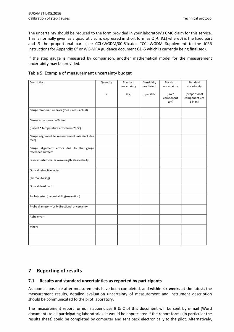
The uncertainty should be reduced to the form provided in your laboratory’s CMC claim for this service. This is normally given as a quadratic sum, expressed in short form as Q[A, B.L] where A is the fixed part and B the proportional part (see CCL/WGDM/00-51c.doc “CCL-WGDM Supplement to the JCRB Instructions for Appendix C“ or WG-MRA guidance document GD-5 which is currently being finalised).
If the step gauge is measured by comparison, another mathematical model for the measurement uncertainty may be provided.
Table 5: Example of measurement uncertainty budget
Description Quantity Standard uncertainty
Sensitivity coefficient
Standard uncertainty
Standard uncertainty
xi u(xi) ci = l/xi (Fixed component
µm)
(proportional component µm
L in m)
Gauge temperature error (measured - actual)
Gauge expansion coefficient
(uncert.* temperature error from 20 °C)
Gauge alignment to measurement axis (includes face)
Gauge alignment errors due to the gauge reference surfaces
Laser interferometer wavelength (traceability)
Optical refractive index
(air monitoring)
Optical dead path
Probe(system) repeatability(resolution)
Probe diameter – or bidirectional uncertainty
Abbe error
others
7 Reporting of results
7.1 Results and standard uncertainties as reported by participants
As soon as possible after measurements have been completed, and within six weeks at the latest, the measurement results, detailed evaluation uncertainty of measurement and instrument description should be communicated to the pilot laboratory.
The measurement report forms in appendices B & C of this document will be sent by e-mail (Word document) to all participating laboratories. It would be appreciated if the report forms (in particular the results sheet) could be completed by computer and sent back electronically to the pilot. Alternatively,
EURAMET L-K5.2016 Calibration of step gauges Technical protocol
results may be submitted in an Excel spreadsheet. In any case, the signed report must also be sent in paper form by mail or electronically as a scanned pdf document. In case of any differences, the signed forms are considered to be the definitive version. Please observe the correct units to be used when reporting results.
Following receipt of all measurement reports from the participating laboratories, the pilot laboratory will analyse the results and prepare within 3 months a first draft A.1 report on the comparison. This will be circulated to the participants for comments, additions and corrections.
8 Analysis of results
8.1 Calculation of the KCRV
The key comparison reference value (KCRV) is calculated as the weighted mean of the participant results. The check for consistency of the comparison results with their associated uncertainties will be made based on Birge ratio, the degrees of equivalence for each laboratory and each interval with respect to the KCRV will be evaluated using En values, along the lines of the WG-MRA-KC-report-template. If necessary, artefact instability, correlations between institutes and the necessity for linking to another comparison will be taken into account.
Note that the measurements made by laboratories participating informally (PTB and Zeiss) will not be included in the KCRV calculation.
8.2 Artefact instability
The stability of the artefacts being used in this comparison was tested by the pilot. But during the transportation and measurement one or both artefacts may be deformed due to temperature change or shock, thus the instability of the artefact must be determined in course of the comparison. For this check the measurements of the pilot laboratory are used exclusively, not those of the other participants. Using these data a linear regression line is fitted and the slope together with its uncertainty is determined.
Three cases can be foreseen: a) The linear regression line is an acceptable drift model and the absolute drift is smaller than its
uncertainty. The artefact is considered stable and no modification to the standard evaluation procedure will be applied. In fact the results of the pilot’s stability measurements will not influence the numerical results in any way.
b) The linear regression line is an acceptable drift model and the absolute drift is larger than its uncertainty, i.e. there is a significant drift for the artefact. In this case an analysis similar to [Nien F Z et al. 2004, Statistical analysis of key comparisons with linear trends, Metrologia 41, 231] will be followed. The pilot influences the KCRV by the slope of the drift only, not by the measured absolute lengths.
c) The data are not compatible at all with a linear drift, regarding the uncertainties of the pilot’s measurements. In this case the artefact is unpredictably unstable or the pilot has problems with its measurements. EURAMET TC-L has to determine the further approach.
8.3 Correlation between laboratories
Since the topic of this project is the comparisons of primary measurements, correlations between the results of different NMIs are unlikely. A possible exception is the common use of the recommended thermal expansion coefficients. A correlation will become relevant only when the step gauge is calibrated far away from 20 °C which should not be the case. Thus correlations are normally not considered in the analysis of this comparison. However if a significant drift exist, correlations between institutes are introduced by the analysis proposed in section 8.2.
EURAMET L-K5.2016 Calibration of step gauges Technical protocol
9 Non-NMI laboratory Participation
9.1 Zeiss
The pilot received a request from Carl Zeiss Industrielle Messtechnik GmbH to participate in the comparison. As a non-NMI they are prohibited from full participation in a key comparison. However the Chair of EURAMET TC-L requested that they be included on an informal “for information only” basis since they are provide a measurement capability similar to many NMIs and are the best measurement capability in their country (Germany). All full participants agreed to the informal inclusion of Carl Zeiss Industrielle Messtechnik GmbH in EURAMET.L-K5-2016 on an informal basis.
As a condition of participation the laboratory is required to agree to the terms and conditions laid down in the CCQM-F-01 form. The signed and approved copy of this form for Zeiss, together with these terms and conditions has been circulated to all participants.
EURAMET L-K5.2016 Calibration of step gauge Technical protocol
CCL-15-13-EURAMET.L-K5-2016 technical protocol v1 7.docx Pg. 22/26
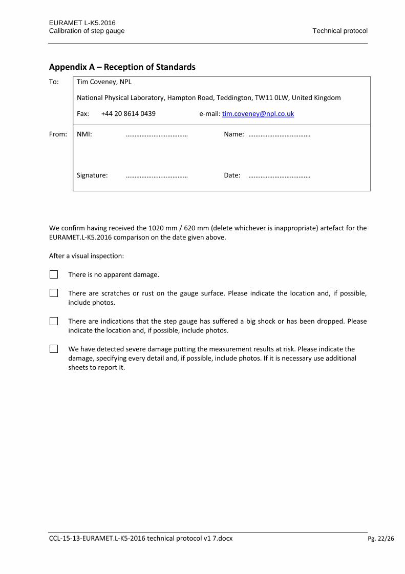
Appendix A – Reception of Standards
To: Tim Coveney, NPL
National Physical Laboratory, Hampton Road, Teddington, TW11 0LW, United Kingdom
Fax: +44 20 8614 0439 e-mail: [email protected]
From: NMI: ……………………………… Name: ………………………………
Signature: ……………………………… Date: ………………………………
We confirm having received the 1020 mm / 620 mm (delete whichever is inappropriate) artefact for the EURAMET.L-K5.2016 comparison on the date given above.
After a visual inspection:
There is no apparent damage.
There are scratches or rust on the gauge surface. Please indicate the location and, if possible, include photos.
There are indications that the step gauge has suffered a big shock or has been dropped. Please indicate the location and, if possible, include photos.
We have detected severe damage putting the measurement results at risk. Please indicate the damage, specifying every detail and, if possible, include photos. If it is necessary use additional sheets to report it.
EURAMET L-K5.2016 Calibration of step gauges Technical protocol
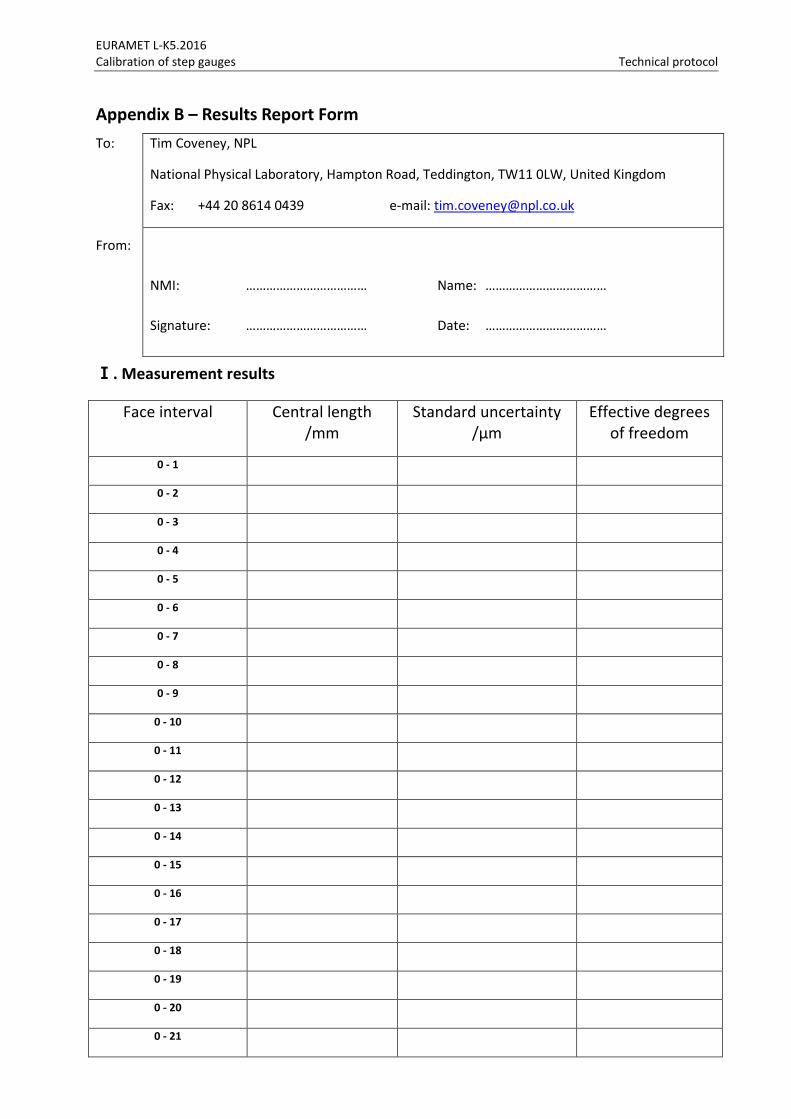
Appendix B – Results Report Form
To: Tim Coveney, NPL
National Physical Laboratory, Hampton Road, Teddington, TW11 0LW, United Kingdom
Fax: +44 20 8614 0439 e-mail: [email protected]
From:
NMI: ……………………………… Name: ………………………………
Signature: ……………………………… Date: ………………………………
Ⅰ. Measurement results
Face interval Central length /mm
Standard uncertainty /µm
Effective degrees of freedom
0 - 1
0 - 2
0 - 3
0 - 4
0 - 5
0 - 6
0 - 7
0 - 8
0 - 9
0 - 10
0 - 11
0 - 12
0 - 13
0 - 14
0 - 15
0 - 16
0 - 17
0 - 18
0 - 19
0 - 20
0 - 21
EURAMET L-K5.2016 Calibration of step gauges Technical protocol
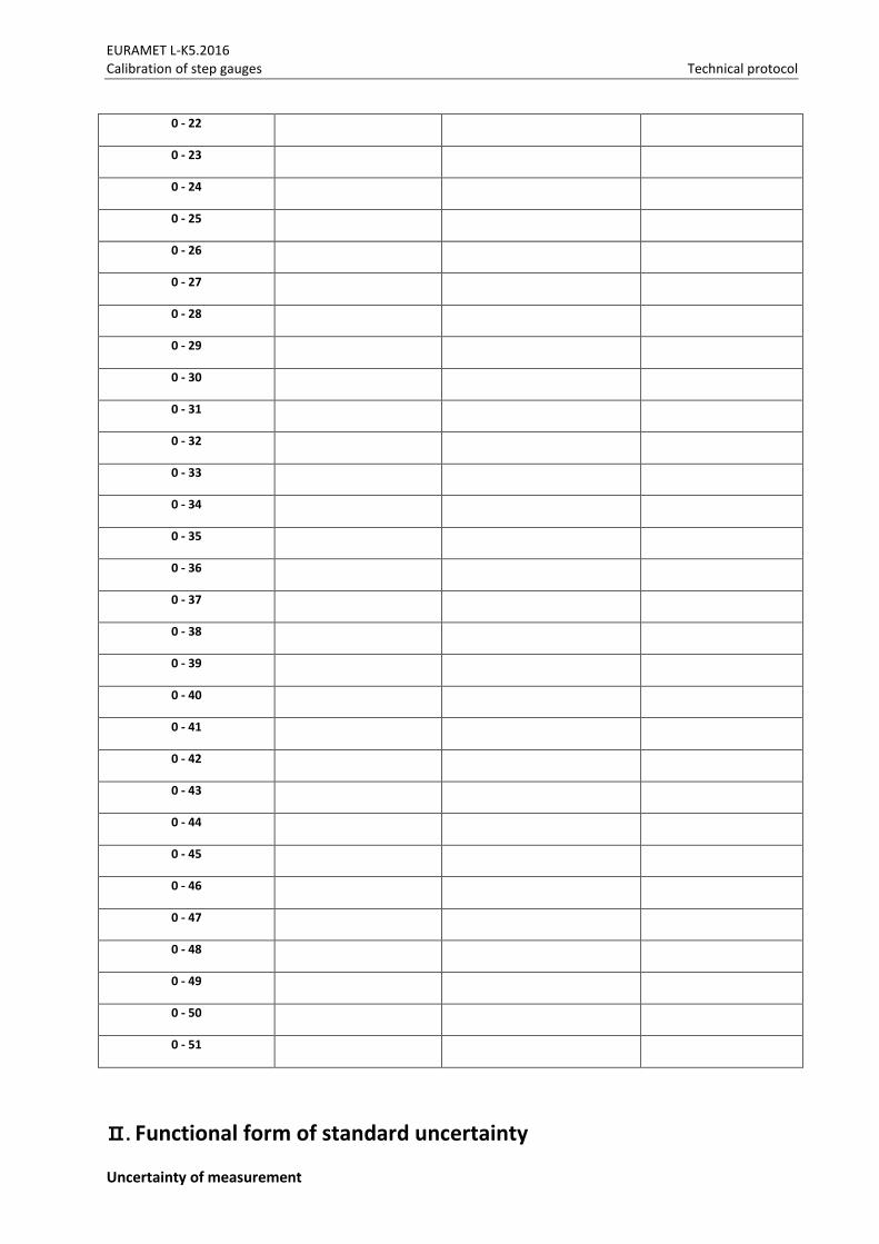
0 - 22
0 - 23
0 - 24
0 - 25
0 - 26
0 - 27
0 - 28
0 - 29
0 - 30
0 - 31
0 - 32
0 - 33
0 - 34
0 - 35
0 - 36
0 - 37
0 - 38
0 - 39
0 - 40
0 - 41
0 - 42
0 - 43
0 - 44
0 - 45
0 - 46
0 - 47
0 - 48
0 - 49
0 - 50
0 - 51
Ⅱ. Functional form of standard uncertainty
Uncertainty of measurement
EURAMET L-K5.2016 Calibration of step gauges Technical protocol
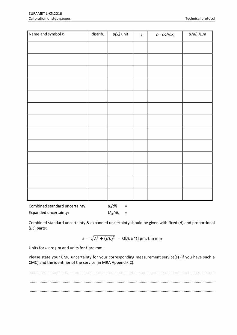
Name and symbol xi distrib. u(xi) unit i ci = dl/xi ui(dl) /µm
Combined standard uncertainty: uc(dl) =
Expanded uncertainty: U95(dl) =
Combined standard uncertainty & expanded uncertainty should be given with fixed (A) and proportional (BL) parts:
𝑢 = √𝐴2 + (𝐵𝐿)2 = Q[A, B*L] µm, L in mm
Units for u are µm and units for L are mm.
Please state your CMC uncertainty for your corresponding measurement service(s) (if you have such a CMC) and the identifier of the service (in MRA Appendix C).
........................................................................................................................................................................
........................................................................................................................................................................
........................................................................................................................................................................

EURAMET L-K5.2016 Calibration of step gauges Technical protocol
If the uncertainty of the CMC is different to the uncertainty claimed for this comparison, please explain why this is the case.
........................................................................................................................................................................
........................................................................................................................................................................
........................................................................................................................................................................
........................................................................................................................................................................
........................................................................................................................................................................
........................................................................................................................................................................
........................................................................................................................................................................
........................................................................................................................................................................
EURAMET L-K5.2016 Calibration of step gauge Technical protocol
CCL-15-13-EURAMET.L-K5-2016 technical protocol v1 7.docx Pg. 27/26
Appendix C –– Description of the measurement instrument
To: Tim Coveney, NPL
National Physical Laboratory, Hampton Road, Teddington, TW11 0LW, United Kingdom
Fax: +44 20 8614 0439 e-mail: [email protected]
From: NMI: ……………………………… Name: ………………………………
Signature: ……………………………… Date: ………………………………
(Use more sheets if necessary, enclose photo(s) and/or sketch(es) of the instrument)
....................................................................................................................................................
....................................................................................................................................................
....................................................................................................................................................
....................................................................................................................................................
....................................................................................................................................................
....................................................................................................................................................
....................................................................................................................................................
....................................................................................................................................................
....................................................................................................................................................
....................................................................................................................................................
....................................................................................................................................................
....................................................................................................................................................