euramet.l-k3.2009.1: report on euramet … › ... › l › k3 ›...
TRANSCRIPT
Report on EURAMET
Bilateral Angle Block Comparison
<Euramet #1321>
EURAMET L-K3.2009.1
Final Report
J. SALGADO (LNE),
Nurul Alfiyati (KIM-LIPI),.
Paris, October 1
EURAMET L-K3.2009.1 Angle Block Bilateral Comparison Draft B.1
Pg. 1/17
Contents
1 Document control ................................................................................................................................ 2 2 Introduction ......................................................................................................................................... 2 3 Organization ......................................................................................................................................... 2
3.1 Participants .................................................................................................................................. 2 3.2 Schedule ....................................................................................................................................... 3
4 Artefacts ............................................................................................................................................... 3 4.1 Description of artefacts ............................................................................................................... 3 4.2 Stability of artefacts ..................................................................................................................... 4 4.3 Condition of artefacts at start/end of comparison ..................................................................... 4
5 Measuring instructions ........................................................................................................................ 4 5.1 Measurands ................................................................................................................................. 4
6 Results .................................................................................................................................................. 5 6.1 Results and standard uncertainties as reported by participants................................................. 5 6.2 Measurement uncertainties ........................................................................................................ 6
7 Analysis ................................................................................................................................................ 6 7.1 Calculation of the KCRV ............................................................................................................... 6 7.2 Calculation of Degrees of Equivalence ........................................................................................ 8 7.3 Discussion of results .................................................................................................................... 8 7.4 Linking of result to other comparisons ........................................................................................ 9 7.5 Conclusions regarding CMCs ........................................................................................................ 9
8 Appendix A: Equipment and measuring processes of the participants............................................. 10 8.1 LNE ............................................................................................................................................. 10 8.2 KIM-LIPI ...................................................................................................................................... 10
9 Appendix B: Uncertainty budgets ...................................................................................................... 12 9.1 LNE ............................................................................................................................................. 12 9.2 KIM-LIPI ...................................................................................................................................... 13
9.2.1 30° Angle block .................................................................................................................. 13 9.2.2 5° Angle block .................................................................................................................... 14 9.2.3 30’ Angle block ................................................................................................................... 15 9.2.4 5’ Angle block ..................................................................................................................... 16 9.2.5 10” Angle block .................................................................................................................. 17

EURAMET L-K3.2009.1 Angle Block Bilateral Comparison Draft B.1
Pg. 2/17
1 Document control
Version Draft A.1 Issued on 01 December 2014. Version Draft A.2 Issued on 09 December 2014. Version Draft B.1 Issued on 17 February 2015. Final Report Issued on 06 July 2015. Final report corrections Issued on 01 October 2015.
2 Introduction
The metrological equivalence of national measurement standards and of calibration certificates issued by national metrology institutes is established by a set of key and supplementary comparisons chosen and organized by the Consultative Committees of the CIPM or by the regional metrology organizations in collaboration with the Consultative Committees.
The comparison is organised within the EU-Indonesia Trade Support Programme II, Sub-project Number APE12-06b, “Improvement of traceability of Metrology and Calibration measurements of Puslit KIM”.
Two National Metrology Institutes take part in this comparison: LNE (France) and KIM-LIPI (Indonesia).
LNE is acting as the pilot laboratory and in this function is responsible for providing the travelling standard, the evaluation of the measurement results and the final report.
The comparison will be accomplished in accordance with the EURAMET Guidelines on Conducting Comparisons and BIPM Guidelines for Planning, Organising, Conducting and Reporting Key, Supplementary and Pilot Comparisons.
The comparison was registered in BIPM KCDB, artefact circulation started in August 2014 and was completed in October 2014.
3 Organization
3.1 Participants
Table 1. List of participant laboratories and their contacts.
Laboratory Code
Contact person, Laboratory Phone, Fax, email
LNE Mr. José SALGADO LNE Laboratoire National de Métrologie et d’Essais 1, rue Gaston Boissier F-75015 Paris France
Tel. +33 1 40 43 39 57 Fax +33 1 40 43 37 37 e-mail: [email protected]
KIM-LIPI Ms. Nurul Alfiyati KIM LIPI :Pusat Penelitian Kalibrasi, Instrumentasi, dan Metrologi Lembaga Ilmu Pengetahuan Indonesia (Puslit KIM-LIPI) Kompleks PUSPIPTEK Gedung 420 Tangerang Selatan, Banten Indonesia
Tel. +62-21-7560533 ext 3078 Fax. +62-21-7560568 e-mail: [email protected]
EURAMET L-K3.2009.1 Angle Block Bilateral Comparison Draft B.1
Pg. 3/17
3.2 Schedule
Table 2. Schedule of the comparison.
RMO Laboratory Original schedule
Date of measurement
Results received
EURAMET LNE August 2014 August 2014 November 2014
APMP KIM-LIPI September 2014 Sept- Oct 2014 November 2014
EURAMET LNE October 2014 Oct – Nov 2014 November 2014
4 Artefacts
4.1 Description of artefacts
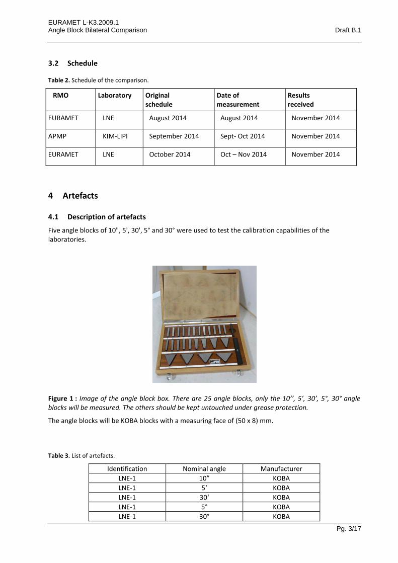
Five angle blocks of 10", 5', 30', 5° and 30° were used to test the calibration capabilities of the laboratories.
Figure 1 : Image of the angle block box. There are 25 angle blocks, only the 10’’, 5’, 30’, 5°, 30° angle blocks will be measured. The others should be kept untouched under grease protection.
The angle blocks will be KOBA blocks with a measuring face of (50 x 8) mm.
Table 3. List of artefacts.
Identification Nominal angle Manufacturer
LNE-1 10” KOBA
LNE-1 5‘ KOBA
LNE-1 30‘ KOBA
LNE-1 5° KOBA
LNE-1 30° KOBA

EURAMET L-K3.2009.1 Angle Block Bilateral Comparison Draft B.1
Pg. 4/17
4.2 Stability of artefacts
Acting as pilot LNE has measured the set of angle block twice. First measurement was performed on August 4th (labelled (1) in Figure 2), the second measurement was performed on October 27th (labelled (2) in Figure 2). The differences between second measurements and first ones is plotted Figure 2, where the errors bars represent the standard uncertainties (k=1). No significant drift is seen within the reported uncertainties at 95% confidence level (k=2).
Figure 2. Stability of 5 angle blocks between the first LNE measurement (1: August 2014) and the second measurement (2: October 2014). In order to have all the values in the same range, the “0” value correspond to the deviation from nominal angle of the first measurements (1) for each angle block. Error bars correspond to the standard uncertainty (k=1).
4.3 Condition of artefacts at start/end of comparison
During the comparison no damage has been noticed for all the angle blocks.
5 Measuring instructions
5.1 Measurands
The angle blocks must be measured using an aperture which is 1 mm less (on the edge) than the overall face.
The autocollimator must be adjusted as precisely as possible, with its optical axis perpendicular and in true alignment to the table’s axis of rotation and central to the centre of the angle block faces.
The angle blocks are to be measured in both the normal and inverted positions, but only the mean will be reported. The angle blocks must be adjusted for eccentricity and must be laterally adjusted so that the measuring faces have a minimum run-out.
The deviation from the nominal angle d = m - n must be reported in seconds.

EURAMET L-K3.2009.1 Angle Block Bilateral Comparison Draft B.1
Pg. 5/17
6 Results
6.1 Results and standard uncertainties as reported by participants
The reported results are shown in Table 4. Both measurement results from LNE are given but only the first one is taken into account for the reference value. Graphs illustrating the results and their uncertainties are plotted in Figure 3.
Figure 3. Results for deviation from nominal angle d in seconds (”) for all of the angle blocks. Error bars: Standard uncertainty (k=1).
Table 4. Deviation from nominal angle (d = m - n) and reported standard uncertainties (k=1) (u) in seconds (“) for each angle block.
10" block 5' block 30' block 5° block 30° block
d (") u (") d (") u (") d (") u (") d (") u (") d (") u (")
LNE 1 0.79 0.10 -2.03 0.10 -0.17 0.10 0.04 0.10 -0.36 0.10
KIM-LIPI 0.97 0.14 -1.05 0.36 0.05 0.14 - 0.29 0.14 - 0.70 0.13
LNE 2 0.75 0.10 -2.02 0.10 -0.13 0.10 0.09 0.10 -0.34 0.10
EURAMET L-K3.2009.1 Angle Block Bilateral Comparison Draft B.1
Pg. 6/17
6.2 Measurement uncertainties
Participants had to submit their uncertainty budget. Details are given in Appendix B. LNE have CMC U = 0,1” on this topic. These CMC assumes that flatness deviation is less than 0,1 µm. Since this was not measured for the angle blocks of this comparison, LNE assumed the maximum flatness deviation admitted by the standards: 0,25 µm. This explains why the uncertainties reported in this comparison are higher than LNE’s CMC.
7 Analysis
7.1 Calculation of the KCRV
Following the recommendations of CCL MRA, we use the weighted mean to compute the reference value. For the following calculations only one of LNE’s (LNE1) results have been taken into account.
The analysis for each measurand proceeds as follows:
We assume the total number of participants submitting a result is I.
Each laboratory reports a measured value, xi , and its associated standard uncertainty u(xi).
We compute the normalised weight, wi , for the result xi given by:
21
i
ixu
Cw (1)
where the normalising factor, C, is given by:
2
1
1
1
I
i ixu
C (2)
Then calculate the weighted mean, wx , which is given by:
I
i
iiw xwx1
(3)
The uncertainty of the weighted mean is calculated by:
C
xu
xuI
i i
w
2
1
1
1)( (4)
After deriving the weighted mean and its associated standard uncertainty, the deviation of each laboratory’s result from the weighted mean is determined simply as wi xx . The uncertainty of this deviation is calculated as a combination of the uncertainties of the result, u(xi) , and the uncertainty of the weighted mean )( wxu . The uncertainty of the deviation from the weighted mean is given by equation (5), which includes a minus sign to take into account the correlation between the two uncertainties (it would be a plus sign if dealing with uncorrelated uncertainties, such as when comparing data from two separate laboratories).
EURAMET L-K3.2009.1 Angle Block Bilateral Comparison Draft B.1
Pg. 7/17
2int
2
wiwi xuxuxxu (5)
For the determination of the key comparison reference value KCRV, statistical consistency of the results contributing to the KCRV is required. A check for statistical consistency of the results with their associated uncertainties can be made by calculating the En value for each laboratory’s result, where En is defined as the ratio of the deviation from the weighted mean, divided by the expanded uncertainty of this deviation – the expanded uncertainty is obtained from the standard uncertainty by multiplying by a suitable value of k to obtain a 95 % confidence level.
2int
2
wi
wi
n
xUxU
xxE
(6)
The results are examined and any for which |En|> 1 is considered as inconsistent result.
A statistically better way to check for consistency than the criterion |En|< 1 is to investigate by the so-called Birge ratio RB which compares the observed spread of the results with the spread expected from the individual reported uncertainties.
The application of least squares algorithms and the 2-test leads to the Birge ratio
w
wextB
xu
xuR , (7)
where )( wext xu is the external standard deviation
I
i
i
I
i
wii
wext
w
xxw
Ixu
1
1
2
1
1. (8)
The Birge ratio has an expectation value of RB = 1, when considering standard uncertainties. For a coverage factor of k = 2, the expectation value is increased and the data in a comparison are consistent provided that
)I/(RB 181 (9)
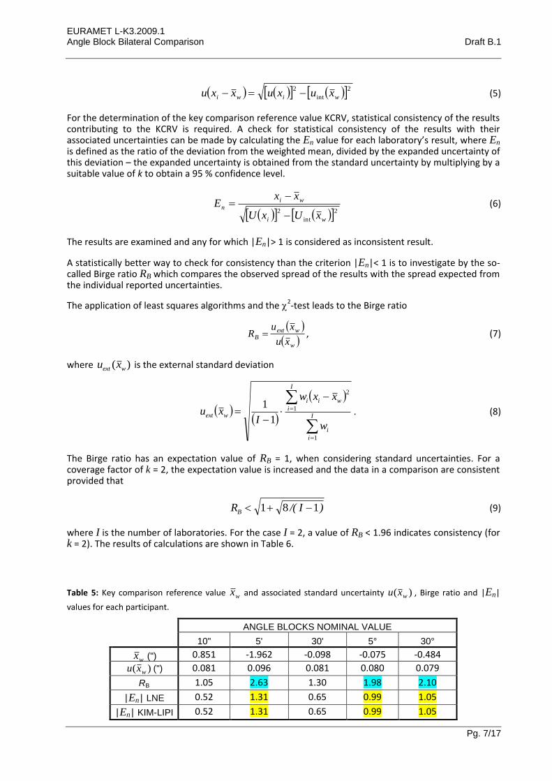
where I is the number of laboratories. For the case I = 2, a value of RB < 1.96 indicates consistency (for k = 2). The results of calculations are shown in Table 6.
Table 5: Key comparison reference value wx and associated standard uncertainty )( wxu , Birge ratio and |En|
values for each participant.
ANGLE BLOCKS NOMINAL VALUE
10" 5' 30' 5° 30°
wx (") 0.851 -1.962 -0.098 -0.075 -0.484
)( wxu (") 0.081 0.096 0.081 0.080 0.079
RB 1.05 2.63 1.30 1.98 2.10
|En| LNE 0.52 1.31 0.65 0.99 1.05
|En| KIM-LIPI 0.52 1.31 0.65 0.99 1.05
EURAMET L-K3.2009.1 Angle Block Bilateral Comparison Draft B.1
Pg. 8/17
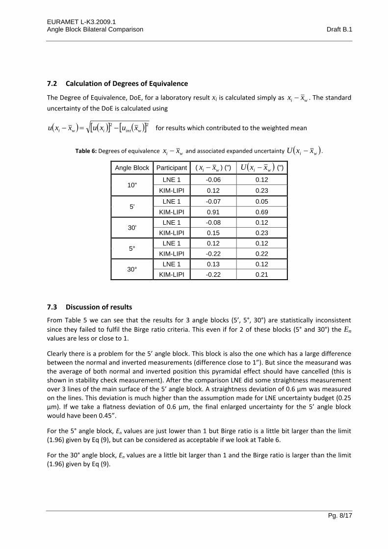
7.2 Calculation of Degrees of Equivalence
The Degree of Equivalence, DoE, for a laboratory result xi is calculated simply as wi xx . The standard
uncertainty of the DoE is calculated using
22
wintiwi xuxuxxu for results which contributed to the weighted mean
Table 6: Degrees of equivalence wi xx and associated expanded uncertainty wi xxU .
Angle Block Participant ( wi xx ) (") wi xxU (")
10" LNE 1 -0.06 0.12
KIM-LIPI 0.12 0.23
5' LNE 1 -0.07 0.05
KIM-LIPI 0.91 0.69
30' LNE 1 -0.08 0.12
KIM-LIPI 0.15 0.23
5° LNE 1 0.12 0.12
KIM-LIPI -0.22 0.22
30° LNE 1 0.13 0.12
KIM-LIPI -0.22 0.21
7.3 Discussion of results
From Table 5 we can see that the results for 3 angle blocks (5’, 5°, 30°) are statistically inconsistent
since they failed to fulfil the Birge ratio criteria. This even if for 2 of these blocks (5° and 30°) the En values are less or close to 1.
Clearly there is a problem for the 5’ angle block. This block is also the one which has a large difference between the normal and inverted measurements (difference close to 1”). But since the measurand was the average of both normal and inverted position this pyramidal effect should have cancelled (this is shown in stability check measurement). After the comparison LNE did some straightness measurement over 3 lines of the main surface of the 5’ angle block. A straightness deviation of 0.6 µm was measured on the lines. This deviation is much higher than the assumption made for LNE uncertainty budget (0.25 µm). If we take a flatness deviation of 0.6 µm, the final enlarged uncertainty for the 5’ angle block would have been 0.45”.
For the 5° angle block, En values are just lower than 1 but Birge ratio is a little bit larger than the limit (1.96) given by Eq (9), but can be considered as acceptable if we look at Table 6.
For the 30° angle block, En values are a little bit larger than 1 and the Birge ratio is larger than the limit (1.96) given by Eq (9).

EURAMET L-K3.2009.1 Angle Block Bilateral Comparison Draft B.1
Pg. 9/17
7.4 Linking of result to other comparisons
Results from this comparison can be linked to the former comparison (CCL L-K3) for 10”, 30’, and 5° angle blocks. This comparison failed to link results for 5’ angle block and case of 30° angle block needs to be discussed.
7.5 Conclusions regarding CMCs
1- LNE’s existing CMCs are unaffected
2- The revised CMC claim at KIM-LIPI cannot be supported by this comparison unless the uncertainties are increased.
EURAMET L-K3.2009.1 Angle Block Bilateral Comparison Draft B.1
Pg. 10/17
8 Appendix A: Equipment and measuring processes of the participants
8.1 LNE
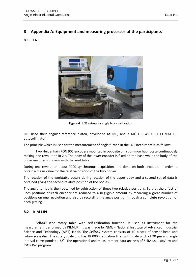
Figure 4 : LNE set-up for angle block calibration
LNE used their angular reference platen, developed at LNE, and a MÖLLER-WEDEL ELCOMAT HR autocollimator.
The principle which is used for the measurement of angle turned in the LNE instrument is as follow:
Two Heidenhain RON 905 encoders mounted in opposite on a common hub rotate continuously making one revolution in 2 s. The body of the lower encoder is fixed on the base while the body of the upper encoder is moving with the worktable.
During one revolution about 9000 synchronous acquisitions are done on both encoders in order to obtain a mean value for the relative position of the two bodies.
The rotation of the worktable occurs during rotation of the upper body and a second set of data is obtained giving the second relative position of the bodies.
The angle turned is then obtained by subtraction of these two relative positions. So that the effect of lines positions of each encoder are reduced to a negligible amount by recording a great number of positions on one revolution and also by recording the angle position through a complete revolution of each grating.
8.2 KIM-LIPI
SelfA47 (the rotary table with self-calibration function) is used as instrument for the
measurement performed by KIM-LIPI. It was made by NMIJ - National Institute of Advanced Industrial Science and Technology (AIST) Japan. The SelfA47 system consists of 10 pieces of sensor head and rotary scale disc. The rotary scale disc has 18 000 graduation lines with scale pitch of 20 µm and angle interval corresponds to 72". The operational and measurement data analysis of SelfA use LabView and IGOR Pro program.

EURAMET L-K3.2009.1 Angle Block Bilateral Comparison Draft B.1
Pg. 11/17
The measurement method uses SelfA47 and autocollimator DA400 from Taylor Hobson. The autocollimator with resolution of 0.1" and a range of +/- 400" is used to read angular deviation of measuring face of angle block. The measurement set up is shown on the following figure:
Figure 5 :KIM-LIPI set up measurement of angle block
Angle block was measured in two different positions, i.e. normal position and inverted position. Each position was measured 5 times. To minimize the influence of electronic error of autocollimator DA400 reading, the average readings of autocollimator was taken with delay time of 2 s. The final result was determined from the average of the two positions (according to technical protocol).
Before performing the measurement, a tilt table has been adjusted to get eccentricity less than 10 µm and also perpendicularity of angle block has been set less than 1".
All measurements were carried out in a laboratory with temperature of (20 ± 0.3) °C and relative humidity of (50 ± 10) %.
EURAMET L-K3.2009.1 Angle Block Bilateral Comparison Draft B.1
Pg. 12/17
9 Appendix B: Uncertainty budgets
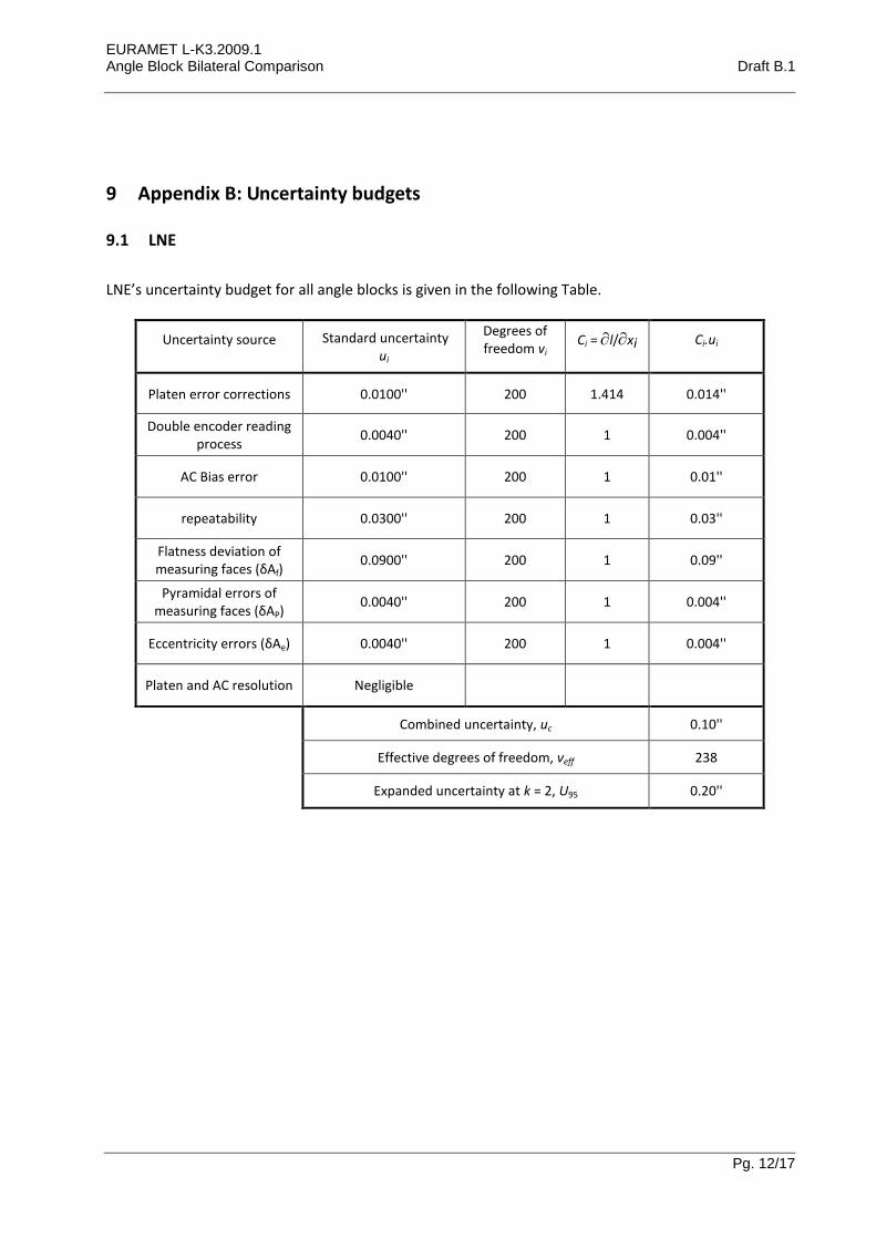
9.1 LNE
LNE’s uncertainty budget for all angle blocks is given in the following Table.
Uncertainty source Standard uncertainty ui
Degrees of freedom vi
Ci = l/xi Ci.ui
Platen error corrections 0.0100'' 200 1.414 0.014''
Double encoder reading process
0.0040'' 200 1 0.004''
AC Bias error 0.0100'' 200 1 0.01''
repeatability 0.0300'' 200 1 0.03''
Flatness deviation of measuring faces (δAf)
0.0900'' 200 1 0.09''
Pyramidal errors of measuring faces (δAP)
0.0040'' 200 1 0.004''
Eccentricity errors (δAe) 0.0040'' 200 1 0.004''
Platen and AC resolution Negligible
Combined uncertainty, uc 0.10''
Effective degrees of freedom, νeff 238
Expanded uncertainty at k = 2, U95 0.20''
EURAMET L-K3.2009.1 Angle Block Bilateral Comparison Draft B.1
Pg. 13/17
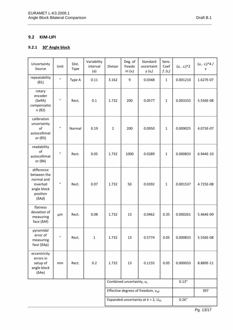
9.2 KIM-LIPI
9.2.1 30° Angle block
Uncertainty Source
Unit Dist. Type
Variability interval
(a) Divisor
Deg. of freedom (νi)
Standard uncertaint
y (ui)
Sens. Coeff. (ci)
(ui . ci)^2 (ui . ci)^4 /
v
repeatability (θ1)
" Type A 0.11 3.162 9 0.0348 1 0.001210 1.627E-07
rotary encoder (SelfA)
compensation (θ2)
" Rect. 0.1 1.732 200 0.0577 1 0.003333 5.556E-08
calibration uncertainty
of autocollimat
or (θ3)
" Normal 0.19 2 200 0.0950 1 0.009025 4.073E-07
readability of
autocollimator (θ4)
" Rect. 0.05 1.732 1000 0.0289 1 0.000833 6.944E-10
difference between the normal and
inverted angle block
position (δAd)
" Rect. 0.07 1.732 50 0.0392 1 0.001537 4.725E-08
flatness deviation of measuring face (δAf)
µm Rect. 0.08 1.732 13 0.0462 0.35 0.000261 5.464E-09
pyramidal error of
measuring face (δAp)
" Rect. 1 1.732 13 0.5774 0.05 0.000833 5.556E-08
eccentricity errors in setup of
angle block (δAe)
mm Rect. 0.2 1.732 13 0.1155 0.05 0.000033 8.889E-11
Combined uncertainty, uc 0.13"
Effective degrees of freedom, νeff 397
Expanded uncertainty at k = 2, U95 0.26"
EURAMET L-K3.2009.1 Angle Block Bilateral Comparison Draft B.1
Pg. 14/17
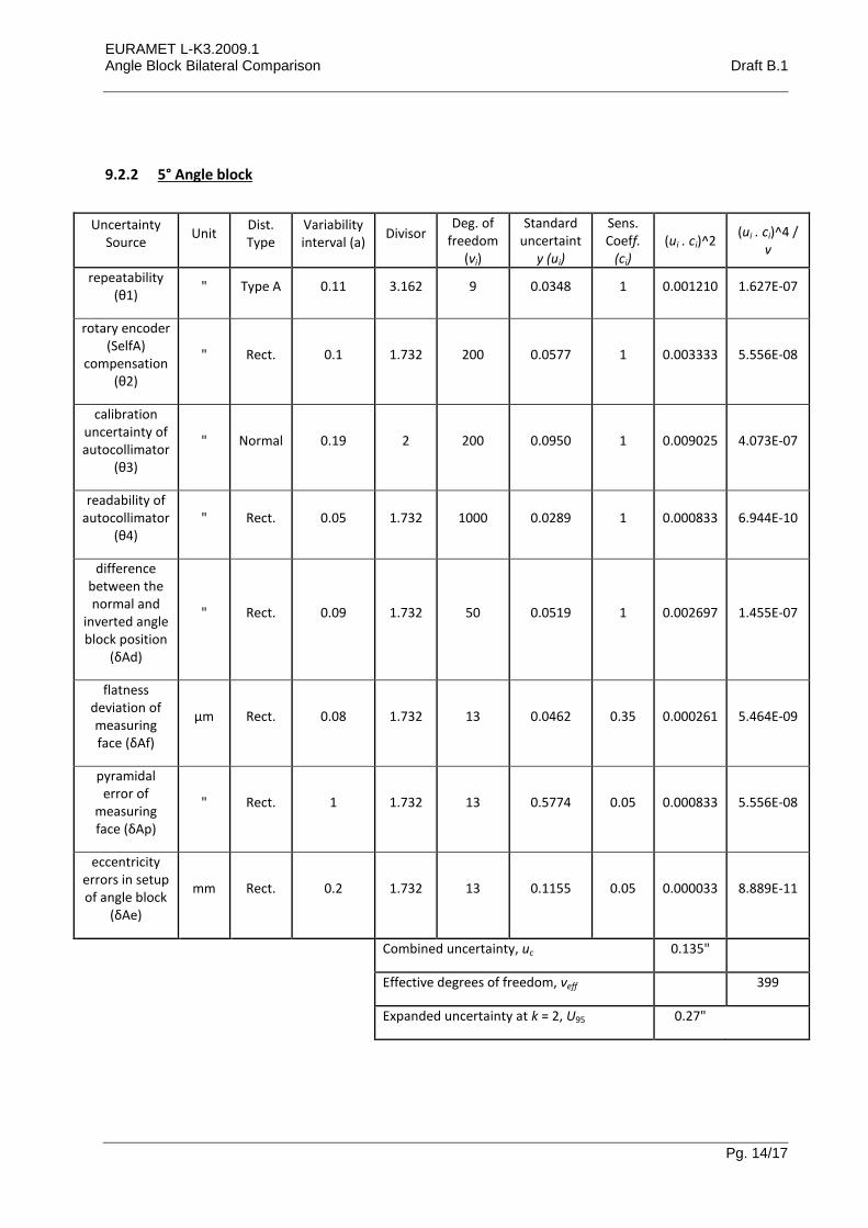
9.2.2 5° Angle block
Uncertainty Source
Unit Dist. Type
Variability interval (a)
Divisor Deg. of
freedom (νi)
Standard uncertaint
y (ui)
Sens. Coeff.
(ci) (ui . ci)^2
(ui . ci)^4 / v
repeatability (θ1)
" Type A 0.11 3.162 9 0.0348 1 0.001210 1.627E-07
rotary encoder (SelfA)
compensation (θ2)
" Rect. 0.1 1.732 200 0.0577 1 0.003333 5.556E-08
calibration uncertainty of autocollimator
(θ3)
" Normal 0.19 2 200 0.0950 1 0.009025 4.073E-07
readability of autocollimator
(θ4) " Rect. 0.05 1.732 1000 0.0289 1 0.000833 6.944E-10
difference between the normal and
inverted angle block position
(δAd)
" Rect. 0.09 1.732 50 0.0519 1 0.002697 1.455E-07
flatness deviation of measuring face (δAf)
µm Rect. 0.08 1.732 13 0.0462 0.35 0.000261 5.464E-09
pyramidal error of
measuring face (δAp)
" Rect. 1 1.732 13 0.5774 0.05 0.000833 5.556E-08
eccentricity errors in setup of angle block
(δAe)
mm Rect. 0.2 1.732 13 0.1155 0.05 0.000033 8.889E-11
Combined uncertainty, uc 0.135"
Effective degrees of freedom, νeff 399
Expanded uncertainty at k = 2, U95 0.27"
EURAMET L-K3.2009.1 Angle Block Bilateral Comparison Draft B.1
Pg. 15/17
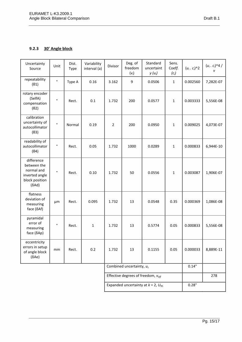
9.2.3 30’ Angle block
Uncertainty Source
Unit Dist. Type
Variability interval (a)
Divisor Deg. of
freedom (νi)
Standard uncertaint
y (ui)
Sens. Coeff.
(ci) (ui . ci)^2
(ui . ci)^4 / v
repeatability (θ1)
" Type A 0.16 3.162 9 0.0506 1 0.002560 7,282E-07
rotary encoder (SelfA)
compensation (θ2)
" Rect. 0.1 1.732 200 0.0577 1 0.003333 5,556E-08
calibration uncertainty of autocollimator
(θ3)
" Normal 0.19 2 200 0.0950 1 0.009025 4,073E-07
readability of autocollimator
(θ4) " Rect. 0.05 1.732 1000 0.0289 1 0.000833 6,944E-10
difference between the normal and
inverted angle block position
(δAd)
" Rect. 0.10 1.732 50 0.0556 1 0.003087 1,906E-07
flatness deviation of measuring face (δAf)
µm Rect. 0.095 1.732 13 0.0548 0.35 0.000369 1,086E-08
pyramidal error of
measuring face (δAp)
" Rect. 1 1.732 13 0.5774 0.05 0.000833 5,556E-08
eccentricity errors in setup of angle block
(δAe)
mm Rect. 0.2 1.732 13 0.1155 0.05 0.000033 8,889E-11
Combined uncertainty, uc 0.14"
Effective degrees of freedom, νeff 278
Expanded uncertainty at k = 2, U95 0.28"
EURAMET L-K3.2009.1 Angle Block Bilateral Comparison Draft B.1
Pg. 16/17
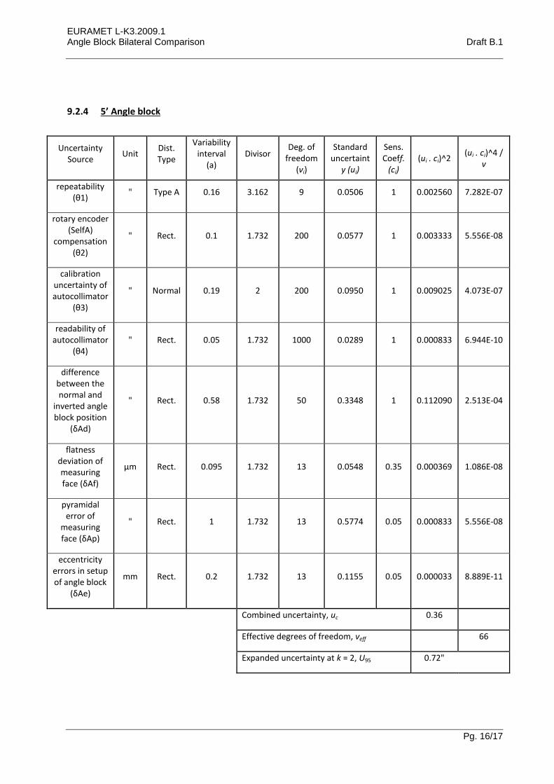
9.2.4 5’ Angle block
Uncertainty Source
Unit Dist. Type
Variability interval
(a) Divisor
Deg. of freedom
(νi)
Standard uncertaint
y (ui)
Sens. Coeff.
(ci) (ui . ci)^2
(ui . ci)^4 / v
repeatability (θ1)
" Type A 0.16 3.162 9 0.0506 1 0.002560 7.282E-07
rotary encoder (SelfA)
compensation (θ2)
" Rect. 0.1 1.732 200 0.0577 1 0.003333 5.556E-08
calibration uncertainty of autocollimator
(θ3)
" Normal 0.19 2 200 0.0950 1 0.009025 4.073E-07
readability of autocollimator
(θ4) " Rect. 0.05 1.732 1000 0.0289 1 0.000833 6.944E-10
difference between the normal and
inverted angle block position
(δAd)
" Rect. 0.58 1.732 50 0.3348 1 0.112090 2.513E-04
flatness deviation of measuring face (δAf)
µm Rect. 0.095 1.732 13 0.0548 0.35 0.000369 1.086E-08
pyramidal error of
measuring face (δAp)
" Rect. 1 1.732 13 0.5774 0.05 0.000833 5.556E-08
eccentricity errors in setup of angle block
(δAe)
mm Rect. 0.2 1.732 13 0.1155 0.05 0.000033 8.889E-11
Combined uncertainty, uc 0.36
Effective degrees of freedom, νeff 66
Expanded uncertainty at k = 2, U95 0.72"

EURAMET L-K3.2009.1 Angle Block Bilateral Comparison Draft B.1
Pg. 17/17
9.2.5 10” Angle block
Uncertainty Source
Unit Dist. Type
Variability interval
(a) Divisor
Deg. of freedom
(νi)
Standard uncertainty
(ui)
Sens. Coeff.
(ci) (ui . ci)^2
(ui . ci)^4 / v
repeatability (θ1)
" Type A 0.12 3.162 9 0.0379 1 0.001440 2.304E-07
rotary encoder (SelfA)
compensation (θ2)
" Rect. 0.1 1.732 200 0.0577 1 0.003333 5.556E-08
calibration uncertainty of autocollimator
(θ3)
" Normal 0.19 2 200 0.0950 1 0.009025 4.073E-07
readability of autocollimator
(θ4) " Rect. 0.05 1.732 1000 0.0289 1 0.000833 6.944E-10
difference between the normal and
inverted angle block position
(δAd)
" Rect. 0.10 1.732 50 0.0568 1 0.003223 2.078E-07
flatness deviation of measuring face (δAf)
µm Rect. 0.095 1.732 13 0.0548 0.35 0.000369 1.086E-08
pyramidal error of
measuring face (δAp)
" Rect. 1 1.732 13 0.5774 0.05 0.000833 5.556E-08
eccentricity errors in setup of angle block
(δAe)
Mm Rect. 0.2 1.732 13 0.1155 0.05 0.000033 8.889E-11
Combined uncertainty, uc 0.14
Effective degrees of freedom, νeff 376
Expanded uncertainty at k = 2, U95 0.28"