european bank for reconstruction and development … · 2.1 site data 7 2.1.1 climatic ... process...
TRANSCRIPT

European Bank for Reconstruction and Development London, UK
Energy Efficiency Investments in the Gas Midstream Sector in Egypt: Feasibility Study and Project Preparation
Dahshour Feasibility Study Report
Doc. No.P0000763-1-H8 Rev.1 - October 2017
Rev. 1
Description Second Issue GASCO comments implemented
Prepared by M. Bogliolo / S. Leo Servidio / P. Ricchetti
Controlled by M. Morando
Approved by G. B. De Franchi
Date October 2017

Doc. No.P0000763-1-H8 Rev.1 - October 2017
RINA CONSULTING Energy Efficiency Investments in the Gas Midstream Sector in Egypt: Feasibility Study and Project Preparation Dahshour Feasibility Study Report
Rev. Description Prepared by Controlled by Approved by Date
1 Second Issue
GASCO comments included
M. Bogliolo S. Leo Servidio
P. Ricchetti M. Morando G. B. De Franchi 06/10/2017
0 First Issue M. Bogliolo
S. Leo Servidio P. Ricchetti
M. Morando G. B. De Franchi 07/09/2017
All rights, including translation, reserved. No part of this document may be disclosed to any third party,
for purposes other than the original, without written consent of RINA Consulting S.p.A.

RINA CONSULTING Energy Efficiency Investments in the Gas Midstream Sector in Egypt: Feasibility Study and Project Preparation Dahshour Feasibility Study Report
Doc. No.P0000763-1-H8 Rev.1 - October 2017
Page 1
TABLE OF CONTENTS
Pag.
LIST OF TABLES 2
LIST OF FIGURES 3
ABBREVIATIONS AND ACRONYMS 4
1 EXECUTIVE SUMMARY 5
2 BASIS OF DESIGN 7
2.1 SITE DATA 7
2.1.1 Climatic conditions 7
2.1.2 Battery Limits 7
2.1.3 Electric Data 7
2.1.4 Gas Characteristics 7
2.2 ENERGY PRICES 8
2.3 OPERATIONAL DATA 8
2.4 GAS NETWORK SCENARIO 9
2.5 CAPEX AND OPEX ESTIMATION 9
2.5.1 CAPEX for Equipment and Materials 9
2.5.2 CAPEX for Services 10
2.5.3 OPEX Estimation 10
3 DAHSHOUR BASELINE OPTION 11
3.1 BASELINE DESCRIPTION 11
3.2 BASELINE PERFORMANCE DATA 12
3.3 BASELINE CAPEX AND OPEX 13
3.3.1 Baseline CAPEX 13
3.3.2 Baseline OPEX 14
4 ENERGY EFFICIENCY SOLUTION DESCRIPTION 15
4.1 OVERVIEW 15
4.2 WASTE HEAT RECOVERY UNITS 18
4.3 HEATING OIL CIRCUIT 19
4.4 ORGANIC RANKINE CYCLE 20
4.5 BALANCE OF PLANT 24
5 EEO PERFORMANCE DATA 25
5.1 CASE SUMMARY 25
5.2 PERFORMANCE TABLES 25
6 FINANCIAL ANALYSIS 30
6.1 CAPEX ESTIMATION 30
6.2 OPEX ESTIMATION 31
6.3 FINANCIAL ANALYSIS RESULTS 32
REFERENCE DOCUMENTS 1
APPENDIX A: EEO EQUIPMENT AND MATERIALS DATA SHEET

RINA CONSULTING Energy Efficiency Investments in the Gas Midstream Sector in Egypt: Feasibility Study and Project Preparation Dahshour Feasibility Study Report
Doc. No.P0000763-1-H8 Rev.1 - October 2017
Page 2
LIST OF TABLES
Table 1.1: Dahshour Financial Summary 6
Table 2.1: Climatic Conditions 7
Table 2.2: Battery Limits 7
Table 2.3: Gas Characteristics 8
Table 3.1: Baseline Performances 12
Table 3.2: Baseline CAPEX 13
Table 3.3: Baseline Resources Consumptions 14
Table 5.1: Rated Performances 26
Table 5.2: Operating Performances 28
Table 6.1: CAPEX for Compression Capacity Extension 30
Table 6.2: CAPEX for EEO Equipment and Materials 30
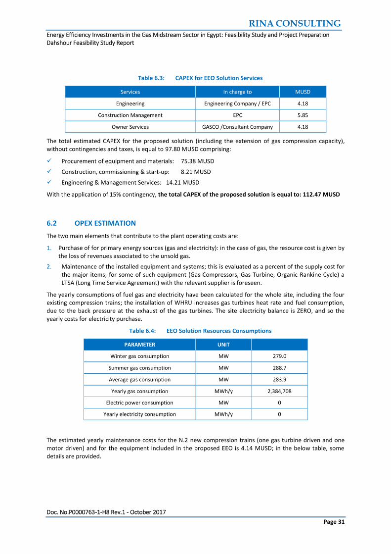
Table 6.3: CAPEX for EEO Solution Services 31
Table 6.4: EEO Solution Resources Consumptions 31
Table 6.5: EEO Solution Maintenance Cost 32
Table 6.6: Electricity Price Forecast 32
Table 6.7: Gas Price Forecast 33

RINA CONSULTING Energy Efficiency Investments in the Gas Midstream Sector in Egypt: Feasibility Study and Project Preparation Dahshour Feasibility Study Report
Doc. No.P0000763-1-H8 Rev.1 - October 2017
Page 3
LIST OF FIGURES
Figure 2.1: Compression Capacity Forecast 9
Figure 3.1: Baseline General Arrangement 11
Figure 4.1: Energy Efficiency Solution Schematic 15
Figure 4.2: Process Flow Diagram 16
Figure 4.3: Compressor Station Layout 17
Figure 4.4: Option 1, compact cylindrical WHRU, Installation above Gas Turbine 19
Figure 4.5: ORC Thermodynamic Chart 20
Figure 4.6: Simplified Process Flow Diagram 21
Figure 4.7: ORC Process Flow Diagram 22
Figure 4.8: ORC General Arrangement 23
Figure 6.1: Cash Flow 34

RINA CONSULTING Energy Efficiency Investments in the Gas Midstream Sector in Egypt: Feasibility Study and Project Preparation Dahshour Feasibility Study Report
Doc. No.P0000763-1-H8 Rev.1 - October 2017
Page 4
ABBREVIATIONS AND ACRONYMS
DCS Distributed Control System
E&S Environmental & Social
EBRD European Bank for Reconstruction and Development
EEO Energy Efficiency Opportunity
EGAS Egyptian Natural Gas Holding Company
ENPPI Engineering for the Petroleum and Process Industries
GASCO Egyptian Natural Gas Company
GC Gas Compressor
GT Gas Turbine
HO Heating Oil
HR Heat Recovery
LHV Low Heating Value
LPG Liquefied petroleum gas
MOIC Ministry of International Cooperation
MOP Egyptian Ministry of Petroleum and Mineral Resources
ND Nominal Diameter
NG Natural Gas
O&M Operation & Maintenance
ORC Organic Rankine Cycle
P Pressure
P&ID Piping and Instrumentation Diagram
PFD Process Flow Diagram
PIP Project Implementation Plan
PP&R Procurement Policies and Rules
SLD Single Line Diagram
RH Relative Humidity
T Temperature
TE Turbo-Expanders
TOC Table of Contents
TOR Terms Of Reference
TS Thermal Supply
UFD Utility Flow Diagram
VFD Variable Frequency Drive
WHRU Waste Heat Recovery Unit

RINA CONSULTING Energy Efficiency Investments in the Gas Midstream Sector in Egypt: Feasibility Study and Project Preparation Dahshour Feasibility Study Report
Doc. No.P0000763-1-H8 Rev.1 - October 2017
Page 5
1 EXECUTIVE SUMMARY
The Dahshour Compression Station includes N.4 gas compression trains of the same size, each of them equipped with a gas turbine drive by GE / Nuovo Pignone, model MS 5002C, in open cycle.
The site capacity is planned to be increased by extending the plant with the installation of N.2 additional compression trains of the same nominal capacity as the existing ones. In view of this expansion, it would be profitable to implement energy efficiency opportunities, by using the large amount of heat available in the gas turbines’ hot exhausts. No thermal users are present at site; for this reason, the proposed solutions are aimed at converting the recovered heat from the gas turbines into electrical power covering both the variable speed motor driven compressor and plant internal electric power requirements through an Organic Rankine Cycle (ORC) Power Plant.
The baseline situation for comparison of costs and benefits of the proposed Solutions is the expansion of the site gas capacity without any energy efficiency measure: it means that two new GT driven additional trains would be installed, with the same capacity of the four existing ones.
A preliminary screening study analyzed four alternatives of Energy Efficiency Opportunities; the selected best option is aimed to drive one of the new compressors by an electric motor with VFD, and use the ORC Power Plant to supply the electrical power needed by the Compression Station in the future configuration; the total recovered duty from 4 running GT is 124.3 MWt and the plant is constituted of the following main equipment:
N.5 waste heat recovery units installed at the outlet of each gas turbine;
Heating oil circuit complete with piping, recirculation pumps, tanks and accessories;
ORC Power Plant with air-cooled condenser;
Balance of plant: foundations and steel structures, electrical and I&C interconnections, utilities extension.
The present feasibility study is aimed to provide energy assessment of the selected solution, performances and conceptual basic documentation (process flow diagram and layout), estimation of CAPEX and OPEX with feedback from suppliers of technological items, schedule and milestones of the project.
A financial analysis has been conducted to evaluate the economic feasibility and the payback time of the selected solution, compared with the above described baseline.
The energy tariffs are as per the ministerial decree 312 of 2017 regarding the fiscal year 2017-2018 and the corresponding savings are based on the escalations that would be anticipated for the change in energy prices due to the country plan for energy prices without subsidy for the future three to five years.
The following table summarises the main findings of the selected solution; a recommended 15% contingencies contribution has been added to the preliminary CAPEX estimation, which is based on budgetary proposal of the most important technological equipment and price estimation for small equipment, materials, and services.

RINA CONSULTING Energy Efficiency Investments in the Gas Midstream Sector in Egypt: Feasibility Study and Project Preparation Dahshour Feasibility Study Report
Doc. No.P0000763-1-H8 Rev.1 - October 2017
Page 6
Table 1.1: Dahshour Financial Summary
PARAMETER UNIT A2
Delta CAPEX with 15% contingency MUSD 33.27
Yearly Natural Gas Savings MWh/y 552,124
Yearly Electricity Savings MWh/y 23,520
GHGs Reduction tCO2/yr 123,290
Delta OPEX for maintenance MUSD/yr -0.76
Average Yearly Energy Savings MUSD/yr 15.25
Payback Time year 2.3
IRR % 45%

RINA CONSULTING Energy Efficiency Investments in the Gas Midstream Sector in Egypt: Feasibility Study and Project Preparation Dahshour Feasibility Study Report
Doc. No.P0000763-1-H8 Rev.1 - October 2017
Page 7
2 BASIS OF DESIGN
2.1 SITE DATA
2.1.1 Climatic conditions
Dahshour Gas Compression Station is located at Dahshour area, about 40 kilometres south of Cairo. The reference climatic conditions of the site are as follows:
Table 2.1: Climatic Conditions
PARAMETER UNIT VALUE
Ambient temperature (min / max) °C +4 / +45
Barometric pressure (min / max) mbar 1009 / 1018
Relative Humidity (min / max) % 54% / 98%
2.1.2 Battery Limits
Battery limits operating conditions for inlet / outlet natural gas are:
Table 2.2: Battery Limits
PARAMETER UNIT INLET OUTLET
Pressure bar(a) min 25.3 / max 50.0 71.0
Temperature °C min 14.6 / max 32.7 max 55
2.1.3 Electric Data
Dahshour compression station is connected with the electrical grid by 2 incoming feeding lines at 22 kV for power supply to the gas compression units, auxiliaries, and buildings.
The medium voltage supply is lowered to 400 V for the users by means of N.3 22kV / 0.4 kV transformers, rated 2.5 MVA each (with other 3 transformers in stand-by), plus N.1 22kV / 0.4 kV transformer rated 1 MVA.
The evaluation of site electric consumption in the different scenarios was based on the following data, referred to normal plant operation:
Auxiliary consumption of 1 gas compressor: 250 kW
Auxiliary consumption of 1 gas turbine drive: 150 kW
Site common utilities: 800 kW
2.1.4 Gas Characteristics
Fuel Gas for the gas turbine drives is taken from the network. A common gas conditioning skid is installed for pressure regulation, heating and filtering the gas to the existing four units; an additional final filtration skid is provided for each gas turbine.

RINA CONSULTING Energy Efficiency Investments in the Gas Midstream Sector in Egypt: Feasibility Study and Project Preparation Dahshour Feasibility Study Report
Doc. No.P0000763-1-H8 Rev.1 - October 2017
Page 8
The characteristics of natural gas compressed in the Dahshour plant are shown in the following table:
Table 2.3: Gas Characteristics
PARAMETER UNIT RICH GAS LEAN GAS
Specific Gravity 0.708 0.567
Gross Heating Value BTU/SCF 980 1180
Gas Composition
Nitrogen %mole 0.05 0.76
Carbon Dioxide %mole 3.99 0.15
Methane %mole 80.23 97.32
Ethane %mole 10.07 1.71
Propane %mole 3.88 0.04
Iso-Butane %mole 0.57 0.02
Normal-Butane %mole 0.69 0.00
Iso-Pentane %mole 0.21 0.00
Normal-Pentane %mole 0.12 0.00
Normal-Hexane %mole 0.12 0.00
Heptane and Heavier %mole 0.07 0.00
Gas Limit Specifications
Hydrogen Sulphide (H2S) ppm vol < 8
Total Sulphur mg / Sm3 < 150
Mercaptan (RSH) mg / Sm3 < 15
Carbon Dioxide %mole < 4.0
Oxygen mole < 0.1
Hydrocarbon Dew Point °C < 5 at any pressure
Water Dew Point °C < 0 at 71 bar(a)
2.2 ENERGY PRICES
The energy prices used for financial analysis are based on a reasonable assumption of possible future prices based on the Consultant experience and on current prices for GASCO:
Electricity price: 44 USD/MWh
Natural Gas price: 0.165USD/Sm3 (equivalent to 17.20 USD/MWh)
2.3 OPERATIONAL DATA
The yearly costs and savings associated to plant operation have been evaluated on the basis of 50 working weeks per year (8,400 operating hours per year).

RINA CONSULTING Energy Efficiency Investments in the Gas Midstream Sector in Egypt: Feasibility Study and Project Preparation Dahshour Feasibility Study Report
Doc. No.P0000763-1-H8 Rev.1 - October 2017
Page 9
2.4 GAS NETWORK SCENARIO
The need of natural gas in the south area of Egypt in increasing, and the necessity of an expansion of Dahshour compression station has already been envisaged by GASCO; from the current operation with N.3 compression trains running at nominal capacity, in the next years two important milestones will be met:
In summer 2019, it is expected that N.4 compression trains will operate at nominal capacity in order to provide the required natural gas flow rate; by that time, GASCO requires that at least one additional compression train is installed and ready for use at Dahshour site (train E);
In summer 2021 it is expected that N.5 compression trains will operate at nominal capacity in order to provide the required natural gas flow rate; by that time, GASCO requires that the sixth additional compression train is installed and ready for use at Dahshour site (train F).
The forecast of natural gas requirement in the next years is shown in the following chart; the identification of the baseline scenario for Dahshour gas compression station is referred to the compression capacity requirement for the site at the date of year 2021.
Figure 2.1: Compression Capacity Forecast
2.5 CAPEX AND OPEX ESTIMATION
CAPEX estimation includes two main voices, associated to Equipment & Materials and to Services; OPEX estimation includes two main voices, associated to costs for resources (fuel gas and electricity) and for plant maintenance.
2.5.1 CAPEX for Equipment and Materials
The cost for equipment and materials is made of two main voices:
1. Procurement (all costs due to the supplier of a specific material, equipment, or package);
2. Construction (all costs due to the contractor of the site erection, commissioning & start-up).
Procurement: all costs associated to the procurement of equipment / materials until they are available at site and ready for installation; in addition, this voice takes into account other goods and services provided by the supplier of the equipment and included in the purchase contract, namely:
0
1
2
3
4
5
0
5
10
15
20
25
30
35
40
45
50
aug-17 aug-18 aug-19 aug-20 aug-21 aug-22 aug-23
nu
mb
er
of
com
pre
ssio
n t
rain
s in
ser
vice
Op
erat
ing
Cap
acit
y (M
Mm
3/d
ay)
Dahshour Compression Capacity- Forecast

RINA CONSULTING Energy Efficiency Investments in the Gas Midstream Sector in Egypt: Feasibility Study and Project Preparation Dahshour Feasibility Study Report
Doc. No.P0000763-1-H8 Rev.1 - October 2017
Page 10
Engineering (inside the scope of supply e.g. a gas compression train, ORC plant);
Supply;
Factory Assembly;
Shop Tests;
Transport to Site;
Documentation and Certificates;
Supervision to Installation and Start-Up (by personnel of the equipment supplier);
Spare Parts for 2 years.
Construction: all costs associated to the site activities required for the installation, commissioning, test, and start-up of the equipment / material or system, until the beginning of the commercial operation, namely:
Site Storage;
Dismantling of existing parts when necessary for the new installation;
Installation (for equipment), Erection, Construction (foundations, building, etc.);
Precommissioning and Commissioning;
Site Tests (construction, SAT).
CAPEX of the most expensive equipment is based on budgetary proposal by some relevant suppliers; at the current degree of engineering development, a 15% contingency factor was added to the estimated CAPEX.
2.5.2 CAPEX for Services
The cost for project services and various activities is divided into the following voices:
1. Engineering (Basic and Detail Design, with the exclusion of engineering for equipment and packages);
2. Construction Management (Site Management, Material Handling, Planning and Cost Control, etc.);
3. Owner Services (Permits, Tender Management, Design Review, Site Supervision, etc.).
2.5.3 OPEX Estimation
The consumption of primary energy sources (natural gas / electricity) is calculated starting from evaluation of heat and material balances in different operating scenarios, which are mainly on different ambient conditions (winter and summer boundaries) and, when applicable, different process scenarios. Each operating scenario is associated to a number of operating hours per year, in order to evaluate the total yearly consumptions and the associated operating costs.
The OPEX associated to plant maintenance is evaluated as a percent of the cost of supply for the major items which are involved in maintenance activities; for some of such equipment (Gas Compressors, Gas Turbine, Organic Rankine Cycle) a LTSA (Long Time Service Agreement) with the relevant supplier is recommended.

RINA CONSULTING Energy Efficiency Investments in the Gas Midstream Sector in Egypt: Feasibility Study and Project Preparation Dahshour Feasibility Study Report
Doc. No.P0000763-1-H8 Rev.1 - October 2017
Page 11
3 DAHSHOUR BASELINE OPTION
3.1 BASELINE DESCRIPTION
The compression station configuration in the baseline scenario includes the extension of the existing four gas compression trains with N.2 new trains, both driven by gas turbines in open cycle; these two additional gas compression trains are for simplicity named train E and train F, respectively.
In the baseline configuration, realization of any energy efficiency measure is not foreseen.
The new trains have been assumed to be identical to the four existing ones, i.e. two gas compressors of the same capacity, each coupled by a gas turbine as mechanical drive; the operating scenario involves N.5 compression trains in service + N.1 compression train in stand-by, at nominal gas capacity.
The compression station capacity extension includes the following main items:
N.2 Gas Compression Trains, of the same capacity as existing ones, each driven by a Gas Turbine in open cycle (including gas coolers and auxiliaries);
Natural Gas filtration and conditioning skids for use as gas turbine fuel;
Process Interconnections to the natural gas main headers at the suction and delivery of the new gas compressors;
Extension of utilities and safety systems (fire & gas detection, fire fighting, vent & flare, compressed air, etc..); electrical and I&C systems (power supply, instrumentation and integration in the existing control system and ESD system);
Foundations and civil work.
The Dahshour site has a dedicated area for the installation of two additional compression trains, as shown in the general arrangement here below; available space is large and allows plant extension without any layout critical aspects, (safety, maintenance, and equipment accessibility).
Figure 3.1: Baseline General Arrangement

RINA CONSULTING Energy Efficiency Investments in the Gas Midstream Sector in Egypt: Feasibility Study and Project Preparation Dahshour Feasibility Study Report
Doc. No.P0000763-1-H8 Rev.1 - October 2017
Page 12
3.2 BASELINE PERFORMANCE DATA
Two different cases have been analysed for the baseline option, associated to the limit seasonal conditions (winter and summer); the performance data are shown in the table below:
Case BW Baseline Performances, Winter Conditions
Case BS Baseline Performances, Summer Conditions
Table 3.1: Baseline Performances
Case Summary
Case identification Case BW Case BS
Air temperature °C 5 45
N° of Gas Compressors in service 5 5
N° of Motor driven compressors 0 0
N° of Gas Turbines driven compressors 5 5
Gas Turbines
Shaft power of each gas turbine kW 17,962 17,962
Gas Turbine heat rate kJ/kWh 13,775 14,254
Natural Gas low heating value kJ/kg 49,097 49,097
1 Gas Turbine fuel consumption kW 68,730 71,120
kg/h 5,040 5,215
GT Exhausts temperature °C 443 560
GT Exhausts Mass Flow kg/s 97.78 88.31
Exhausts Composition total %mol 100.00% 100.00%
N2 %mol 75.61% 72.29%
O2 %mol 15.53% 13.65%
Ar %mol 0.91% 0.86%
CO2 %mol 2.39% 2.88%
H2O %mol 5.57% 10.31%
Site electric consumptions (process)
Gas Compressors aux consumption kW 1,250 1,250
Gas Turbines aux consumption kW 750 750
MV Motor and VFD consumption kW
Site common utilities consumption kW 800 800
Margin for startup & upgrades kW
Total site process consumption kW 2,800 2,800
Electric balance
Site process consumption kW 2,800 2,800
HO system consumption kW
ORC auxiliary consumption kW
ACC electric consumption kW
Other EEO electric consumption kW
Total site electric consumption kW 2,800 2,800
SITE ELECTRIC BALANCE kW -2,800 -2,800

RINA CONSULTING Energy Efficiency Investments in the Gas Midstream Sector in Egypt: Feasibility Study and Project Preparation Dahshour Feasibility Study Report
Doc. No.P0000763-1-H8 Rev.1 - October 2017
Page 13
The increase in compression capacity will cause an increase in the fuel gas consumption for the two additional GTs in service, and an increase of the plant electric consumption for the auxiliaries of the two new compression trains (gas compressors + gas turbines).
Each gas turbine works at 17,962 shaft power and requires about 69.9 MW of fuel gas input power, with about 150 kW electric auxiliary consumption (mainly for lube oil fan cooler, control panel, HVAC); each gas compressor has about 250 kW electric auxiliary consumption (mainly for after cooler fans).
The yearly gas and electricity consumptions have been evaluated on the basis of 8,400 working hours per year, which correspond to 50 operating weeks; they are evaluated as additional consumptions associated to the installation of the new trains, both with gas turbine drives in open cycle.
3.3 BASELINE CAPEX AND OPEX
The estimations of CAPEX and OPEX associated to the baseline for Dahshour gas compression station is used for comparison of the correspondent data of the energy efficiency based solution, to perform a financial analysis based on the difference between the two alternatives.
3.3.1 Baseline CAPEX
The following table shows the CAPEX estimation for the baseline option, including Equipment & Materials (split between Procurement and Construction, as described below in chapter 2), and Services.
Table 3.2: Baseline CAPEX
Equipment / Material Qty. Procurement
MUSD Construction
MUSD
Gas Compression Trains (Gas Turbine driven) 2 52.20 0.60
Gas Process Interconnections LOT 0.32 0.25
Foundations LOT 0.90 1.35
Steel Structures LOT 0.35 0.53
Electric Equipment and Materials LOT 0.54 0.28
I&C Equipment and Materials LOT 0.57 0.31
Utilities extension LOT 0.44 0.23
Services In charge to MUSD
Engineering Engineering Company / EPC 2.94
Construction Management EPC 4.12
Owner Services GASCO /Consultant Company 2.94
The estimated CAPEX for baseline, without contingencies and taxes, is equal to 68.87 MUSD comprising:
Procurement of equipment and materials: 55.32 MUSD;
Construction, commissioning & start-up: 3.55 MUSD;
Engineering & Management Services: 10.00 MUSD.
With the application of 15% contingency, the total CAPEX for the baseline option is equal to: 79.20 MUSD

RINA CONSULTING Energy Efficiency Investments in the Gas Midstream Sector in Egypt: Feasibility Study and Project Preparation Dahshour Feasibility Study Report
Doc. No.P0000763-1-H8 Rev.1 - October 2017
Page 14
3.3.2 Baseline OPEX
The two main elements that contribute to the plant operating costs are:
1. Purchase of for primary energy sources (gas and electricity): in the case of gas, the resource cost is given by the loss of revenues associated to the unsold gas;
2. Maintenance of the installed equipment and systems; this is evaluated as a percent of the supply cost for the major items.
The yearly consumptions of fuel gas and electricity have been calculated for the whole site, including the four existing compression trains; the gas consumption is based on the average fuel gas flow to the gas turbines between the winter and summer conditions, where the gas turbines have different heat rates.
Table 3.3: Baseline Resources Consumptions
PARAMETER UNIT
Winter gas consumption MW 343.6
Summer gas consumption MW 355.6
Average gas consumption MW 349.6
Yearly gas consumption MWh/y 2,936,832
GHG emission for gas consumption ton CO2 /yr 593,240
Electric power consumption MW 2.8
Yearly electricity consumption MWh/y 23,520
GHG emission for electricity consumption ton CO2 /yr 11,784
The estimated yearly maintenance cost for the N.2 new compression trains + gas turbine drives is 4.90 MUSD, assuming an yearly cost equal to 10% of the supply CAPEX for a long time service agreement contract.

RINA CONSULTING Energy Efficiency Investments in the Gas Midstream Sector in Egypt: Feasibility Study and Project Preparation Dahshour Feasibility Study Report
Doc. No.P0000763-1-H8 Rev.1 - October 2017
Page 15
4 ENERGY EFFICIENCY SOLUTION DESCRIPTION
4.1 OVERVIEW
In this scenario the two new gas compression trains E and F will be equipped as follows:
one additional gas compressor (train E) driven by a gas turbine, identical to the four existing ones;
one additional gas compressor (train F) driven by an electric motor with VFD.
This solution is aimed to recover only the necessary heat to produce the electric power required for the site self consumptions (including the new motor), without exporting electricity to the external grid: however, it will be connected to the grid to maintain stability and to use grid as backup in case of ORC failure; the basic assumption for this solution is that it will not be possible to export electric power to the grid. As a result, a small part of the heat available in the gas turbine exhausts will not be recovered.
The plant will be composed of the following main equipment:
N.5 waste heat recovery units installed at the outlet of each gas turbine (four existing and one new);
heating oil circuit complete with piping, recirculation pumps, tanks and accessories;
organic Rankine cycle for electric power generation; it will include evaporator, turbine, condenser, circulation pump, and electric generator; the gross power output of the turbine will be equal to the total site electric consumptions.
Balance of plant: foundations and steel structures, electrical and I&C interconnections, utilities extension.
In normal operation five compression trains will be in service: 4 trains will be driven by gas turbines, and the fifth train will be the one driven by the new electric motor.
A schematic of the configuration with nominal performance data is shown below; a process flow diagram and the layout of the installation are provided in the following pictures.
Figure 4.1: Energy Efficiency Solution Schematic
TRAIN E
spare
TURBINE FOR
ELECTRIC
POWER GEN.
3.7
MWe
TRAIN B
TRAIN D
31
MWt
GRID
WHRU
ORGANIC RANKINE CYCLE
18.7
MWe
HEATING
OIL
CIRCUIT
SITE CONSUMPTIONS
(PROCESS - UTILITIES)
(WHRU - HEATING OIL)
GT
MS5002 C
EVAPORATOR
& OTHER
EQUIPMENT
WHRU
TRAIN F MOTOR
WITH VFD
WHRU
0
MWe
NEW GT
MS5002 C
WHRU
GC
SITE
ELECTRIC
BALANCE
123
MWtGC
HEAT RECOVERY (HR)
GC
TRAIN A
GT
MS5002 C
GT
MS5002 C31
MWt
ORC AUXILIARY
CONSUMPTION
31
MWt
24.6
MWe
2.2
MWe
GC
31
MWt
GC
GT
MS5002 C
WHRU
GC
TRAIN C

RINA CONSULTING Energy Efficiency Investments in the Gas Midstream Sector in Egypt: Feasibility Study and Project Preparation Dahshour Feasibility Study Report
Doc. No.P0000763-1-H8 Rev.1 - October 2017
Page 16
Figure 4.2: Process Flow Diagram

RINA CONSULTING Energy Efficiency Investments in the Gas Midstream Sector in Egypt: Feasibility Study and Project Preparation Dahshour Feasibility Study Report
Doc. No.P0000763-1-H8 Rev.1 - October 2017
Page 17
Figure 4.3: Compressor Station Layout

RINA CONSULTING Energy Efficiency Investments in the Gas Midstream Sector in Egypt: Feasibility Study and Project Preparation Dahshour Feasibility Study Report
Doc. No.P0000763-1-H8 Rev.1 - October 2017
Page 18
4.2 WASTE HEAT RECOVERY UNITS
Waste heat recovery units are heat exchangers that recover the heat from the gas turbines exhaust gases to heat a thermal oil fluid (heat vector).
In order to ensure operation of compressor trains in any conditions, the proposed arrangement is the twin stack one: the existing exhaust stack will be kept and a duct piece including a three-way diverter will be installed between turbine exhaust and stack; the WHRU will have its own stack.
This will allow to completely by-pass the WHRU in case of ORC unit unavailability and/or heating oil circuit shut-down without overheating (and thus coking) the oil residues in the coil.
Furthermore, since the unit is not designed for dry running, material of construction is carbon steel.
By-pass diverter is a three-way twin set dampers mechanically linked, pneumatically actuated, with fail-close action of bypass.
The design and installation of WHRUs shall be checked and approved by the gas turbines manufacturer (GE), since they must comply with all requirements and specifications of the existing gas turbines, in particular:
The backpressure at the gas turbine discharge generated by the WHRU shall be, in any operating condition, within the limits indicated by the gas turbine manufacturer;
The installation of the WHRU shall not cause limitations or interference with the maintenance activities on the gas compressors / gas turbine drives, including space necessary for lifting and handling of the main components which may be subject to disassembly from the package.
The WHRU will be of the compact circular concentric helical coil type (used in offshore) installed above the turbine.
The installation does not entail modification to exhaust duct and turbine auxiliaries: the existing exhaust stack will be kept and a duct piece including a three-way diverter will be installed between turbine exhaust and stack.
Steel structures and relevant foundations need to be installed to support both duct with diverter and WHRU with its own stack.
Installation of WHRUs will be done shutting down one compression train at a time, and increasing the loads of the other trains. In case of above ground installation, the crane will lift the turbine stack and then will place the assembly WHRU-transition duct-diverter damper (single lift) on the already erected supporting structure.
Installation time is 3-5 days.
The tube is constituted by a helical finned coil tube, installed concentrically in a compact circular casing.
This construction offers the following key advantages for a brownfield installation:
High efficiency;
Low pressure drop gas side (i.e. gas turbines performances are not affected);
Compact footprint;
Reduced weight and hence smaller supporting structure;
Low wind resistance;
Single lift item (installation is easy and fast).
The coil is connected to inlet and outlet headers.
Data and performance of this WHRU can be found in the data-sheet in Appendix A.

RINA CONSULTING Energy Efficiency Investments in the Gas Midstream Sector in Egypt: Feasibility Study and Project Preparation Dahshour Feasibility Study Report
Doc. No.P0000763-1-H8 Rev.1 - October 2017
Page 19
Figure 4.4: Option 1, compact cylindrical WHRU, Installation above Gas Turbine
4.3 HEATING OIL CIRCUIT
Hot oil circuit is composed by the following components:
1. Heating Oil circulation pumps;
2. Side filter sized for the 10% of oil flow, provided to remove debris from piping and solid residues due to oil coking;
3. Storage tank sized for the full oil inventory in case of emptying of the circuit for maintenance or oil replacement with filling pumps;
4. Expansion drum sized for thermal expansion of full volume from minimum ambient temperature to design temperature, blanketed with nitrogen, located at an elevation higher than top of WHRU;
5. Drain drum sized for the expansion drum volume in case of leakage with vertical pumps;
6. Intercept valves (manual and actuated), control valves, thermal relief valves; line accessories and instruments required for a and reliable and safe operation.
The heating oil circuit piping will have two main headers from and to WHRUs of nominal size 20”, will be routed on the existing pipe rack located between compression trains and aftercoolers.
DIVERTER DAMPER
EXISTING STACK
WHRU
NEW WHRU STACK
EXISTING SILENCER

RINA CONSULTING Energy Efficiency Investments in the Gas Midstream Sector in Egypt: Feasibility Study and Project Preparation Dahshour Feasibility Study Report
Doc. No.P0000763-1-H8 Rev.1 - October 2017
Page 20
All pumps will be compliant to API 610 and API 682 (mechanical seals); circulation and filling pumps will be vertical in-line, OH3 type in order to minimize footprint. Mechanical seals will be provided with dedicated closed circuit air-cooling systems. Heating oil circuit is not composed by any long lead items, therefore it will be installed and commissioned before WHRUs and ORC delivery.
For detailed information regarding the equipment, please refer to data-sheets in Appendix A.
4.4 ORGANIC RANKINE CYCLE
The ORC plant produces electricity and discharges heat at low-temperature as secondary product through a closed thermodynamic cycle, which follows the principle of the Organic Rankine Cycle (ORC).
In the ORC process, designed as a closed cycle, the organic working medium (cyclopentane) is pre-heated and vaporized through heat exchange with the thermal oil. The generated vapour is expanded in a turbine that drives a generator. Leaving the turbine, the organic working medium (still in the vapour phase) passes through the regenerator that is used to pre-heat the organic liquid before vaporizing, therefore, increasing the electric efficiency through internal heat recovery; the organic vapour then condenses in an air-cooled condenser.
After the condenser, the working medium is brought back to the pressure level required (for turbine operation) by the working fluid feed pump and then preheated by internal heat exchange in the regenerator. The condensing heat is delivered to the cooling system, given by the air-cooled condenser.
Figure 4.5: ORC Thermodynamic Chart

RINA CONSULTING Energy Efficiency Investments in the Gas Midstream Sector in Egypt: Feasibility Study and Project Preparation Dahshour Feasibility Study Report
Doc. No.P0000763-1-H8 Rev.1 - October 2017
Page 21
Figure 4.6: Simplified Process Flow Diagram
The operation of the ORC plant is fully automatic in normal operating conditions as well as in shut down procedures without any need of supervision personnel. In case of faulty conditions, the ORC plant will be switched off automatically and separated from the hot source circuit and from the electrical connection to the Compressor Station.
The ORC module is designed to automatically adjust itself to the actual operating conditions: variations on hot and cold sources temperatures and flows (in reasonable span times) will not affect the functionality of the system (but just the power output).
In case of fault, the ORC turbogenerator automatically and safely stops, and the Electric Generator disconnects from the plant.
When operating at partial load the process parameters and the Electric Power output automatically change self-adapting to the available Thermal Power.
The organic fluid vapour is expanded in the turbine and the internal energy of the vapour is converted into mechanical energy. Thanks to the thermodynamic properties of the organic fluid adopted, the vapour that flows in the turbines is superheated (dry vapour), with evident benefits in terms of wear and tear of the mechanical components.
For detailed information regarding the equipment, please refer to data-sheets in Appendix A.
EXPANDER
GENERATOR
REGENERATOR
AIR CONDENSER
EVAPORATOR
PREHEATER

RINA CONSULTING Energy Efficiency Investments in the Gas Midstream Sector in Egypt: Feasibility Study and Project Preparation Dahshour Feasibility Study Report
Doc. No.P0000763-1-H8 Rev.1 - October 2017
Page 22
Figure 4.7: ORC Process Flow Diagram

RINA CONSULTING Energy Efficiency Investments in the Gas Midstream Sector in Egypt: Feasibility Study and Project Preparation Dahshour Feasibility Study Report
Doc. No.P0000763-1-H8 Rev.1 - October 2017
Page 23
Space requirement of ORC Plant is mainly dictated by air cooled condenser, as shown in General Arrangement in figure 4-10; since the system uses indirect heat exchange through heating oil, it can be located in any area of the Compressor Station. The area identified for ORC Plant is the free area west of the flare (figure 4-3).
Figure 4.8: ORC General Arrangement

RINA CONSULTING Energy Efficiency Investments in the Gas Midstream Sector in Egypt: Feasibility Study and Project Preparation Dahshour Feasibility Study Report
Doc. No.P0000763-1-H8 Rev.1 - October 2017
Page 24
4.5 BALANCE OF PLANT
All auxiliaries needed for proper operation of the Plant and for the interconnection will be included.
This comprises bulk materials such as steel structures, piping supports, instruments, electrical cables and junction boxes, the equipment for grid interconnection (switchboards and panels), thermal insulation, interconnection to existing DCS, connection to and extension of utilities:
Venting and flare;
Instrument air;
Fire-water;
Closed drain;
Open drain;
Fire and gas;
Emergency electrical power connection;
UPS system.
Membrane type nitrogen generator package and nitrogen circuit will be added for purging/blanketing of ORC Plant and heating oil system.
Adequacy of existing instrument/service air compressor capacity will be checked in order to ensure new plants requirements; if necessary, the air compressor used for nitrogen generation will be sized to cover also instrument air additional consumption and new service air connections.
All new piping and cables will follow as much as possible the routing of the existing pipe racks and cableways.
A new pipe rack will be erected crossing the roads to flare and to emergency gate: this rack will host the hot oil headers from/to ORC Power Plant.
For detailed information regarding the equipment, please refer to data-sheets in Appendix A.

RINA CONSULTING Energy Efficiency Investments in the Gas Midstream Sector in Egypt: Feasibility Study and Project Preparation Dahshour Feasibility Study Report
Doc. No.P0000763-1-H8 Rev.1 - October 2017
Page 25
5 EEO PERFORMANCE DATA
5.1 CASE SUMMARY
The preliminary evaluation of the performances of the selected solution has included different operational cases, which provide useful information for the sizing of the main equipment and for the estimation of the yearly costs and savings.
In all cases the plant compression capacity is relevant to future scenario 2021, with N.6 compression trains installed (four existing and two new ones), and N.5 compression trains in service at nominal capacity. One new gas compressor is driven by a medium voltage electric motor, and the power supply is provided by the generator of the ORC plant.
Four different cases have been analysed, which result from the combination of two seasonal conditions (winter and summer extreme conditions) with two different degrees of performance levels:
1. Rated Performances;
2. Operating Performances.
The Rated Performances represent the sizing cases for the main equipment and packages, the Operating Performances show the real conditions during the plant operation, and provide data for the calculations of yearly costs and savings associated to operation.
The difference between the two scenarios is the net power output of the ORC generator, which is 600 kW higher in the Rated Performances data, to take into account additional power for compressor train start-up and future increase of the site consumptions.
In all cases the site electric balance is ZERO, which means that the power generated by the ORC plant equals the sum of all the site consumptions.
The four cases are summarized and identified as follows:
Case RW Rated Performances, Winter Conditions
Case RS Rated Performances, Summer Conditions
Case OW Operating Performances, Winter Conditions
Case OS Operating Performances, Summer Conditions
5.2 PERFORMANCE TABLES
In the following tables the performance data for the rated cases (RW, RS – winter and summer) and the operating cases (OW, OS – winter and summer) are shown.
The results show that the sizing case for the waste heat recovery units is in winter, due to the lower gas turbine exhausts temperature; in summer conditions, the required performances of electric site balance are obtained with a fraction of the exhausts sent to the by-pass (respectively 19% for rated and 21% for operating cases), because the duty available in the exhausts is higher than in winter.

RINA CONSULTING Energy Efficiency Investments in the Gas Midstream Sector in Egypt: Feasibility Study and Project Preparation Dahshour Feasibility Study Report
Doc. No.P0000763-1-H8 Rev.1 - October 2017
Page 26
Table 5.1: Rated Performances
Case Summary
Case identification Case RW Case RS
Air temperature °C 5 45
N° of Gas Compressors in service 5 5
N° of Motor driven compressors 1 1
N° of Gas Turbines driven compressors 4 4
Gas Turbines
Shaft power of each gas turbine kW 17,962 17,962
Gas Turbine heat rate kJ/kWh 13,982 14,468
Natural Gas low heating value kJ/kg 49,097 49,097
1 Gas Turbine fuel consumption kW 69,761 72,186
kg/h 5,115 5,293
GT Exhausts temperature °C 443 560
GT Exhausts Mass Flow kg/s 97.78 88.31
Exhausts Composition total %mol 100.00% 100.00%
N2 %mol 75.61% 72.29%
O2 %mol 15.53% 13.65%
Ar %mol 0.91% 0.86%
CO2 %mol 2.39% 2.88%
H2O %mol 5.57% 10.31%
1 WHRU gas side
bypass % opening % 0% 19%
GT exhausts flow through WHRU kg/s 97.78 71.58
GT exhausts flow through bypass kg/s 0.00 16.73
Gas at coil inlet temperature °C 443 560
Gas at coil outlet temperature °C 155 175
Gas temperature at stack °C 155 248
GT exhausts recovered duty MWt 30.4 31.1
1 WHRU heating oil side
HO recovered duty MWt 30.41 31.08
HO inlet temperature °C 120 157
HO outlet temperature °C 270 310
HO specific heat (average) kJ/kg-C 2.25 2.25
HO density kg/m3 900 900
HO flow rate kg/s 90.0 90.0
m3/h 360 360
1 WHRU overall
Cold side temperature approach °C 35 18
LMTD °C 87 89
UxA kW/°C 351 351
heat transfer area (finned) m2 9,227 9,227

RINA CONSULTING Energy Efficiency Investments in the Gas Midstream Sector in Egypt: Feasibility Study and Project Preparation Dahshour Feasibility Study Report
Doc. No.P0000763-1-H8 Rev.1 - October 2017
Page 27
heat transfer coefficient (finned) W/m2-C 38.0 38.0
Heating Oil Circuit
Return temperature (WHRU inlet) °C 120 157
HO total flow rate m3/h 1,440 1,440
Pressure drop - WHRUs bar 2.0 2.0
Pressure drop - piping & valves bar 3.0 3.0
Pressure drop - allowances bar 1.0 1.0
Total HO system pressure drop bar 6.0 6.0
HO pumps required head m 68.0 68.0
margin over pump required head % 6% 6%
HO pumps chosen head m 72.0 72.0
HO pumps thermodynamic efficiency 70% 70%
HO pumps electric efficiency % 92% 92%
Total HO pumps consumption kW 395 395
HO other consumptions and margin % 14% 14%
Total HO system ELE consumption kW 450 450
Organic Rankine Cycle
Total GT exhausts recovered duty MWt 121.6 124.3
HO circuit heat losses % 1% 1%
Thermal Duty transferred to ORC MWt 120.4 123.1
ORC gross efficiency (turbine + gen) % 20.0% 20.0%
ORC gross power output MWt 24.1 24.6
Site electric consumptions (process)
Gas Compressors aux consumption kW 1.250 1.250
Gas Turbines aux consumption kW 600 600
MV Motor and VFD consumption kW 18.700 18.700
VFD chiller kW 150 150
Site common utilities consumption kW 800 800
Margin for startup & upgrades kW 600 600
Total site process consumption kW 22.100 22.100
Electric balance
Site process consumption kW 22.100 22.100
HO system consumption kW 450 450
ORC auxiliary consumption kW 1.325 1.846
ACC electric consumption kW 361 369
Other EEO electric consumption kW 0 0
Total site electric consumption kW 24.236 24.765
SITE ELECTRIC BALANCE kW -150 -150

RINA CONSULTING Energy Efficiency Investments in the Gas Midstream Sector in Egypt: Feasibility Study and Project Preparation Dahshour Feasibility Study Report
Doc. No.P0000763-1-H8 Rev.1 - October 2017
Page 28
Table 5.2: Operating Performances
Case Summary
Case identification Case OW Case OS
Air temperature °C 5 45
N° of Gas Compressors in service 5 5
N° of Motor driven compressors 1 1
N° of Gas Turbines driven compressors 4 4
Gas Turbines
Shaft power of each gas turbine kW 17,962 17,962
Gas Turbine heat rate kJ/kWh 13,982 14,468
Natural Gas low heating value kJ/kg 49,097 49,097
1 Gas Turbine fuel consumption kW 69,761 72,186
kg/h 5,115 5,293
GT Exhausts temperature °C 443 560
GT Exhausts Mass Flow kg/s 97.78 88.31
Exhausts Composition total %mol 100.00% 100.00%
N2 %mol 75.61% 72.29%
O2 %mol 15.53% 13.65%
Ar %mol 0.91% 0.86%
CO2 %mol 2.39% 2.88%
H2O %mol 5.57% 10.31%
1 WHRU gas side
bypass % opening % 0% 21%
GT exhausts flow through WHRU kg/s 97.78 70.03
GT exhausts flow through bypass kg/s 0.00 18.28
Gas at coil inlet temperature °C 443 560
Gas at coil outlet temperature °C 163 177
Gas temperature at stack °C 163 257
GT exhausts recovered duty MWt 29.6 30.2
1 WHRU heating oil side
HO recovered duty MWt 29.60 30.25
HO inlet temperature °C 129 161
HO outlet temperature °C 275 310
HO specific heat (average) kJ/kg-C 2.25 2.25
HO density kg/m3 900 900
HO flow rate kg/s 90.0 90.0
m3/h 360 360
1 WHRU overall
Cold side temperature approach °C 35 17
LMTD °C 84 86
UxA kW/°C 351 351
heat transfer area (finned) m2 9,227 9,227

RINA CONSULTING Energy Efficiency Investments in the Gas Midstream Sector in Egypt: Feasibility Study and Project Preparation Dahshour Feasibility Study Report
Doc. No.P0000763-1-H8 Rev.1 - October 2017
Page 29
heat transfer coefficient (finned) W/m2-C 38.0 38.0
Heating Oil Circuit
Return temperature (WHRU inlet) °C 129 161
HO total flow rate m3/h 1,440 1,440
Pressure drop - WHRUs bar 2.0 2.0
Pressure drop - piping & valves bar 3.0 3.0
Pressure drop - allowances bar 1.0 1.0
Total HO system pressure drop bar 6.0 6.0
HO pumps required head m 68.0 68.0
margin over pump required head % 6% 6%
HO pumps chosen head m 72.0 72.0
HO pumps thermodynamic efficiency 70% 70%
HO pumps electric efficiency % 92% 92%
Total HO pumps consumption kW 395 395
HO other consumptions and margin % 14% 14%
Total HO system ELE consumption kW 450 450
Organic Rankine Cycle
Total GT exhausts recovered duty MWt 118.4 121.0
HO circuit heat losses % 1% 1%
Thermal Duty transferred to ORC MWt 117.2 119.8
ORC gross efficiency (turbine + gen) % 20.0% 20.0%
ORC gross power output MWt 23.4 24.0
Site electric consumptions (process)
Gas Compressors aux consumption kW 1.250 1.250
Gas Turbines aux consumption kW 600 600
MV Motor and VFD consumption kW 18.700 18.700
VFD chiller kW 150 150
Site common utilities consumption kW 800 800
Margin for startup & upgrades kW
Total site process consumption kW 21.500 21.500
Electric balance
Site process consumption kW 21.500 21.500
HO system consumption kW 450 450
ORC auxiliary consumption kW 1.289 1.797
ACC electric consumption kW 352 359
Other EEO electric consumption kW 0 0
Total site electric consumption kW 23.591 24.106
SITE ELECTRIC BALANCE kW -150 -150

RINA CONSULTING Energy Efficiency Investments in the Gas Midstream Sector in Egypt: Feasibility Study and Project Preparation Dahshour Feasibility Study Report
Doc. No.P0000763-1-H8 Rev.1 - October 2017
Page 30
6 FINANCIAL ANALYSIS
6.1 CAPEX ESTIMATION
The CAPEX estimation for the proposed energy efficiency solution was divided into three main groups:
1. The capacity extension of the gas compressor station, with the installation of N.2 new compression trains (one driven by gas turbine and one driven by electric motor);
2. The installation of the waste heat recovery system on the exhausts of N.5 gas turbines, the heating oil circuit, and the Organic Rankine Cycle plant with electric generator, including a new MV panel to feed the electric motor and interconnection with the existing electric system;
3. Engineering Services, Construction Management, and other Owner Services that were evaluated on the overall amount of purchased goods and works.
The following tables illustrate the various contributions to the project cost.
Table 6.1: CAPEX for Compression Capacity Extension
Equipment / Material Qty. Procurement
MUSD Construction
MUSD
Gas Compression Trains (Gas Turbine driven) 1 26.10 0.30
Gas Compression Trains (MV Motor driven) 1 16.80 0.45
Gas Process Interconnections LOT 0.32 0.25
Foundations LOT 0.90 1.35
Steel Structures LOT 0.35 0.53
Electric Equipment and Materials LOT 0.79 0.51
I&C Equipment and Materials LOT 0.57 0.31
Utilities extension LOT 0.44 0.23
Table 6.2: CAPEX for EEO Equipment and Materials
Equipment / Material Qty. Procurement
MUSD Construction
MUSD
WHRU 5 7.09 0.37
Heating Oil Circuit LOT 1.59 0.60
Organic Rankine Cycle Plant LOT 16.73 1.04
Foundations LOT 1.23 1.07
Steel Structures LOT 0.52 0.05
Electric Equipment LOT 0.63 0.49
I&C Equipment LOT 0.38 0.25
Utilities extension LOT 0.76 0.24
HO Thermal Insulation LOT 0.18 0.17
RINA CONSULTING Energy Efficiency Investments in the Gas Midstream Sector in Egypt: Feasibility Study and Project Preparation Dahshour Feasibility Study Report
Doc. No.P0000763-1-H8 Rev.1 - October 2017
Page 31
Table 6.3: CAPEX for EEO Solution Services
Services In charge to MUSD
Engineering Engineering Company / EPC 4.18
Construction Management EPC 5.85
Owner Services GASCO /Consultant Company 4.18
The total estimated CAPEX for the proposed solution (including the extension of gas compression capacity), without contingencies and taxes, is equal to 97.80 MUSD comprising:
Procurement of equipment and materials: 75.38 MUSD
Construction, commissioning & start-up: 8.21 MUSD
Engineering & Management Services: 14.21 MUSD
With the application of 15% contingency, the total CAPEX of the proposed solution is equal to: 112.47 MUSD
6.2 OPEX ESTIMATION
The two main elements that contribute to the plant operating costs are:
1. Purchase of for primary energy sources (gas and electricity): in the case of gas, the resource cost is given by the loss of revenues associated to the unsold gas.
2. Maintenance of the installed equipment and systems; this is evaluated as a percent of the supply cost for the major items; for some of such equipment (Gas Compressors, Gas Turbine, Organic Rankine Cycle) a LTSA (Long Time Service Agreement) with the relevant supplier is foreseen.
The yearly consumptions of fuel gas and electricity have been calculated for the whole site, including the four existing compression trains; the installation of WHRU increases gas turbines heat rate and fuel consumption, due to the back pressure at the exhaust of the gas turbines. The site electricity balance is ZERO, and so the yearly costs for electricity purchase.
Table 6.4: EEO Solution Resources Consumptions
PARAMETER UNIT
Winter gas consumption MW 279.0
Summer gas consumption MW 288.7
Average gas consumption MW 283.9
Yearly gas consumption MWh/y 2,384,708
Electric power consumption MW 0
Yearly electricity consumption MWh/y 0
The estimated yearly maintenance costs for the N.2 new compression trains (one gas turbine driven and one motor driven) and for the equipment included in the proposed EEO is 4.14 MUSD; in the below table, some details are provided.

RINA CONSULTING Energy Efficiency Investments in the Gas Midstream Sector in Egypt: Feasibility Study and Project Preparation Dahshour Feasibility Study Report
Doc. No.P0000763-1-H8 Rev.1 - October 2017
Page 32
Table 6.5: EEO Solution Maintenance Cost
ITEM / SYSTEM OPEX estimation
Yearly costs (% of supply)
OPEX estimation Yearly costs
MUSD
Gas Compressor with Gas Turbine drive 10% 2.45
Gas Compressor with Motor drive and VFD 5% 0.76
WHRU and Heating Oil Circuit 2% 0.15
Organic Rankine Cycle and Generator 5% 0.78
6.3 FINANCIAL ANALYSIS RESULTS
When compared with the baseline option, the proposed solution shows a higher initial capital expenditure, with significant yearly savings related to the lower gas consumption and net electricity site balance. Maintenance costs for the EEO proposed solution will be lower than the ones for the baseline, because the installed ORC plant is subject to lower maintenance than the gas turbine used in the baseline.
The comparison between the investigated EEO and the baseline option leads to the following main data:
The CAPEX difference between the EEO solution and the baseline option is 33.27 MUSD;
The OPEX difference between the EEO solution and the baseline option is -0.76 MUSD;
The yearly electrical savings of the EEO are: 23,520 MWh/year;
The yearly natural gas savings of the EEO are: 552,124 MWh/year;
The average yearly energy savings of the EEO are 15.25 MUSD/year;
The payback time of the proposed Energy Efficiency solution is: 2.3 years.
For the financial analysis, RINA Consulting has used the Egyptian official prices forecast for electricity and gas, as reported in the following table.
Table 6.6: Electricity Price Forecast
Medium Voltage Power Supply (22 or 11 kV)
Fiscal Year 2016-2017
2017-2018
2018-2019
2019-2020
2020-2021
2021-2022
2022-2023
2023-2024
2024-2025
Energy Tariff (EGP/kWh)
0.52 0.60 0.64 0.69 0.74 0.79 0.84 0.90 0.96
Maximum Demand Charge
(EGP/kW/month) 45 60 63 67 71 75 79 83 88
Average Energy Tariff (EGP/kWh)
equivalent to Maximum Demand
Charge
0.095 0.126 0.133 0.141 0.150 0.158 0.166 0.175 0.185
Total Average Billed Energy (EGP/kWh)
0.61 0.73 0.77 0.83 0.88 0.94 1.01 1.08 1.15
USD/MWh 34.16 40.36 43.04 46.01 49.15 52.47 56.00 59.74 63.83

RINA CONSULTING Energy Efficiency Investments in the Gas Midstream Sector in Egypt: Feasibility Study and Project Preparation Dahshour Feasibility Study Report
Doc. No.P0000763-1-H8 Rev.1 - October 2017
Page 33
Table 6.7: Gas Price Forecast
Natural Gas Tariff
Fiscal Year 2016-2017
2017-2018
2018-2019
2019-2020
2020-2021
2021-2022
2022-2023
2023-2024
2024-2025
Natural Gas Tariff for non
intensive energy
consumers (USD/MMBtu)
5.00 5.00 5.50 6.00 6.00 7.00 7.00 7.50 7.50
USD/MWh 17.06 17.06 18.76 20.47 20.47 23.88 23.88 25.59 25.59
In case GASCO provides dedicated price forecast for this specific site, RINA Consulting will add a different financial scenario.
Detailed results of the financial analysis are illustrated in the following Figure.

RINA CONSULTING Energy Efficiency Investments in the Gas Midstream Sector in Egypt: Feasibility Study and Project Preparation Dahshour Feasibility Study Report
Doc. No.P0000763-1-H8 Rev.1 - October 2017
Page 34
Figure 6.1: Cash Flow
MARBO/SERLE/PAORI/MARMO/GIODE:chrtx
Operation Year 2020 2021 2022 2023 2024 2025 2026 2027 2028 2029 2030 2031 2032 2033 2034 2035
Operation Period - 1 2 3 4 5 6 7 8 9 10 11 12 13 14 15
Benefits from Raw Materials Saving - - - - - - - - - - - - - - -
Benefits from Energy Saving 12,458 14,420 14,503 15,533 15,629 15,629 15,629 15,629 15,629 15,629 15,629 15,629 15,629 15,629 15,629
Benefits from Water saving - - - - - - - - - - - - - - -
Other Revenues / Saving 760 760 760 760 760 760 760 760 760 760 760 760 760 760 760
Gross Profit - 13,218 15,180 15,263 16,293 16,389 16,389 16,389 16,389 16,389 16,389 16,389 16,389 16,389 16,389 16,389
Investment Costs 33,266- - - - - - - - - - - - - - - -
Net Cash Flow 33,266- 13,218 15,180 15,263 16,293 16,389 16,389 16,389 16,389 16,389 16,389 16,389 16,389 16,389 16,389 16,389
Discounted Cash Flow 33,266- 12,239 13,015 12,117 11,976 11,154 10,328 9,563 8,855 8,199 7,591 7,029 6,508 6,026 5,580 5,167
Discount Factor 8.0%
Pay Back Period (PB) 2.32 years
Internal Rate of Return (IRR) 45%
Net Present Value (NPV) USD
Benefit over Cost Ratio ( BCR) 4.07
102,081,000

RINA CONSULTING Energy Efficiency Investments in the Gas Midstream Sector in Egypt: Feasibility Study and Project Preparation Dahshour Feasibility Study Report
Doc. No.P0000763-1-H8 Rev.1 - October 2017
Page R-1
REFERENCE DOCUMENTS
3231-200-KED-001 Rev 2 Electrical One Line Diagram (7 Sheets)
3231-200-KPE-100 Rev 9 Plot Plan
- Gas Turbine Data Sheet MS5002C (Nuovo Pignone)
- Gas Turbine Performance Curves MS5002C (Nuovo Pignone)
- Gas Turbine Layout Drawings MS5002C (Nuovo Pignone)
4656-330-ACA-001 Rev0 Dahshour Compression Station Units E&F - Process Design Basis
4656-330-RT-001 Rev0 Dahshour Compression Station Units E&F - Driver selection study
4656-330-KXB-01/02/03 Dahshour Compression Station Units E&F - PFD & Balances Rev. 0
- Dahshour Compression Station Units E&F – Request for Quotation and Technical / Commercial Proposals by Suppliers of new gas compressors (gas turbine driven and motor driven alternatives).
- Dahshour Compression Station Units E&F – Request for Quotation and Technical / Commercial Proposals by Suppliers of Organic Rankine Cycle for power generation (from gas turbine waste heat recovery).
P0000763-1-H2_rev1 Energy Efficiency Investments in the Gas Midstream Sector in Egypt: Feasibility Study and Project Preparation.
Dahshour Technology Screening Report

AP
PEN
DIX
A
Appendix A EEO Equipment and Materials Data Sheet Doc. No.P0000763-1-H8 Rev.1 - October 2017
RINA CONSULTING ENERGY EFFICIENCY INVESTMENTS IN THE GAS MIDSTREAM SECTOR IN EGYPT: FEASIBILITY STUDY AND PROJECT PREPARATION Appendix A
Doc. No.P0000763-1-H8 Rev.1 - October 2017
Page A-1
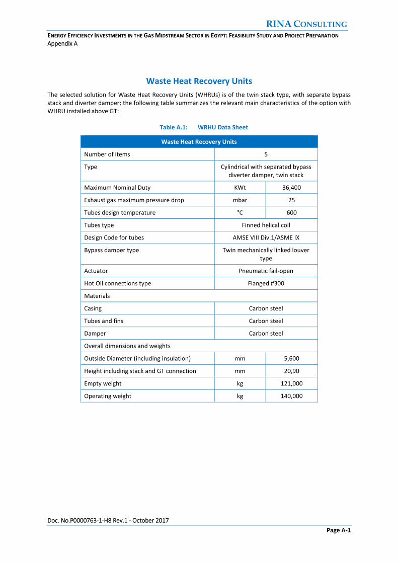
Waste Heat Recovery Units
The selected solution for Waste Heat Recovery Units (WHRUs) is of the twin stack type, with separate bypass stack and diverter damper; the following table summarizes the relevant main characteristics of the option with WHRU installed above GT:
Table A.1: WRHU Data Sheet
Waste Heat Recovery Units
Number of items 5
Type Cylindrical with separated bypass diverter damper, twin stack
Maximum Nominal Duty KWt 36,400
Exhaust gas maximum pressure drop mbar 25
Tubes design temperature °C 600
Tubes type Finned helical coil
Design Code for tubes AMSE VIII Div.1/ASME IX
Bypass damper type Twin mechanically linked louver type
Actuator Pneumatic fail-open
Hot Oil connections type Flanged #300
Materials
Casing Carbon steel
Tubes and fins Carbon steel
Damper Carbon steel
Overall dimensions and weights
Outside Diameter (including insulation) mm 5,600
Height including stack and GT connection mm 20,90
Empty weight kg 121,000
Operating weight kg 140,000

RINA CONSULTING ENERGY EFFICIENCY INVESTMENTS IN THE GAS MIDSTREAM SECTOR IN EGYPT: FEASIBILITY STUDY AND PROJECT PREPARATION Appendix A
Doc. No.P0000763-1-H8 Rev.1 - October 2017
Page A-2
Heating Oil Circulation Pumps
The heating oil circulation pumps are chosen in 3x50% redundancy because of high total capacity; since space constraint is not an issue, horizontal pumps will be used. The following table summarizes the equipment characteristics.
Table A.2: Heating Oil Circulation Pumps Data Sheet
Heating Oil Circulation Pumps
Number of items 3 x 50%
Fluid Thermal Oil
Rated capacity m3/h 750
Rated head m 72
Shutoff head m < 90
Design Pressure barg 20
Design Temperature °C 350
Reference Codes API 610, API 682
Pump type Centrifugal horizontal radially split, between bearing (BB1)
Impeller type Closed
Seal type Tandem cartridge mechanical seal, balanced, with metal bellows, air cooling package included
Materials API CLASS S-6
Casing
Impeller
Shaft
carbon steel
12% Chromium Steel AISI 420
Motor voltage V 6,000
Motor rated power kW 220
Dimensions (mm) Length
Width
3,000
1,500
Weight kg 4,000

RINA CONSULTING ENERGY EFFICIENCY INVESTMENTS IN THE GAS MIDSTREAM SECTOR IN EGYPT: FEASIBILITY STUDY AND PROJECT PREPARATION Appendix A
Doc. No.P0000763-1-H8 Rev.1 - October 2017
Page A-3
Heating Oil Filling Pumps
These pumps are dedicated to circuit filling and they take suction from the heating oil storage tank; N° 2x100% pumps will be installed, centrifugal horizontal type; the main relevant data are shown below.
Table A.3: Heating Oil Filling Pumps Data Sheet
Heating Oil Filling Pumps
Number of items 2 x 100%
Fluid Thermal Oil
Rated capacity m3/h 50
Rated head m 50
Shutoff head m <90
Design Pressure barg 20
Design Temperature °C °C
Reference Codes API 610, API 682
Pump type Centrifugal, horizontal centreline mounted, OH3 API Type
Impeller type Closed
Seal type Tandem cartridge mechanical seal, balanced, with metal bellows, air cooling package included
Materials API CLASS S-6
Casing
Impeller
Shaft
carbon steel
12% Chromium Steel AISI 420
Motor voltage V 400
Motor rated power kW 11
Dimensions (mm) skid
height
1,000
500
Weight kg 200

RINA CONSULTING ENERGY EFFICIENCY INVESTMENTS IN THE GAS MIDSTREAM SECTOR IN EGYPT: FEASIBILITY STUDY AND PROJECT PREPARATION Appendix A
Doc. No.P0000763-1-H8 Rev.1 - October 2017
Page A-4
Heating Oil Drain Drum Pumps
These pumps are dedicated to discharge the heating oil drain drum and send the heating oil to the storage tank; N° 2x100% pumps will be installed, centrifugal horizontal type; the main relevant data are shown below.
Table A.4: Heating Oil Drain Drum Pumps Data Sheet
Heating Oil Drain Drum Pumps
Number of items 2 x 100%
Fluid Thermal Oil
Rated capacity m3/h 25
Rated head m 50
Shutoff head m < 90
Design Pressure barg 20
Design Temperature °C 350
Reference Codes API 610, API 682
Pump type Centrifugal, Vertical VS2 API Type
Impeller type Closed
Seal type Tandem cartridge mechanical seal, balanced, with metal bellows, air cooling package included
Materials API CLASS S-5
Casing
Impeller
Shaft
Carbon steel
12% Chromium Steel AISI 420
Motor voltage V 400
Motor rated power kW 7,5
Dimensions (mm) Shaft length 4 m
Weight kg 500

RINA CONSULTING ENERGY EFFICIENCY INVESTMENTS IN THE GAS MIDSTREAM SECTOR IN EGYPT: FEASIBILITY STUDY AND PROJECT PREPARATION Appendix A
Doc. No.P0000763-1-H8 Rev.1 - October 2017
Page A-5
Heating Oil Storage Tank
The main storage tank is sized for the total heating circuit inventory volume; the main data are shown below.
Table A.5: Heating Oil Storage Tank Data Sheet
Heating Oil Storage Tank
Number of items 1
Fluid Thermal Oil
Type Vertical, fixed conical roof
Reference Codes API 650
Blanketing Nitrogen, inlet / outlet pressure control valves
Design Pressure barg 5
Design Temperature °C 350
Corrosion allowance mm 3
Material carbon steel
Finishing Internal / external painting
Heat Insulation YES
Geometric Volume m3 410
Available Volume m3 304
Dimensions (mm) diameter
height
9,000
6,500
Weight (kg) dry
operating
60,000
424,000

RINA CONSULTING ENERGY EFFICIENCY INVESTMENTS IN THE GAS MIDSTREAM SECTOR IN EGYPT: FEASIBILITY STUDY AND PROJECT PREPARATION Appendix A
Doc. No.P0000763-1-H8 Rev.1 - October 2017
Page A-6
Heating Oil Expansion Drum
The heating oil expansion drum is sized to recover the volume increase of the circuit total inventory from ambient temperature to maximum operating temperature; this drum must be installed at the highest point of the heating oil circuit, in particular above the top elevation of the WHRUs. The main data are shown below.
Table A.6: Heating Oil Expansion Drum Data Sheet
Heating Oil Expansion Drum
Number of items 1
Fluid Thermal Oil
Type Horizontal cylindrical
Reference Codes
Blanketing Nitrogen, inlet / outlet pressure control valves
Design Pressure barg 5
Design Temperature °C 350
Material carbon steel
Finishing Internal / external painting
Corrosion allowance mm 3
Heat Insulation YES
Geometric Volume m3 85
Available Volume m3 64
Dimensions (mm) diameter
length
3,400
10,000
Weight (kg) dry
operating
20,000
97,000

RINA CONSULTING ENERGY EFFICIENCY INVESTMENTS IN THE GAS MIDSTREAM SECTOR IN EGYPT: FEASIBILITY STUDY AND PROJECT PREPARATION Appendix A
Doc. No.P0000763-1-H8 Rev.1 - October 2017
Page A-7
Heating Oil Drain Drum
The heating oil drain drum is sized to recover the volume of heating oil deriving from the drainage of the item with the maximum heating oil inventory: this is the case of the expansion drum. For this reason, the heating oil drain drum will be of the same geometry and size. The main data are shown below.
Table A.7: Heating Oil Drain Drum Data Sheet
Heating Oil Drain Drum
Number of items 1
Fluid Thermal Oil
Type Horizontal cylindrical
Reference Codes
Blanketing Nitrogen, inlet / outlet pressure control valves
Design Pressure barg 5
Design Temperature °C 350
Corrosion allowance mm 3
Material carbon steel
Finishing Internal / external painting
Heat Insulation YES
Geometric Volume m3 85
Available Volume m3 64
Dimensions (mm) diameter
length
3,400
10,000
Weight (kg) dry
operating
20,000
97,000

RINA CONSULTING ENERGY EFFICIENCY INVESTMENTS IN THE GAS MIDSTREAM SECTOR IN EGYPT: FEASIBILITY STUDY AND PROJECT PREPARATION Appendix A
Doc. No.P0000763-1-H8 Rev.1 - October 2017
Page A-8
Organic Rankine Cycle
The ORC Power Plant is sized to produce the electric power required by Compression Station plus a margin for future users.
The Evaporator is the first heat exchanger to receive heat from thermal oil; here evaporation of cyclopentane take place.
Table A.8: Evaporator Data Sheet
ORC evaporator
Number of items 1
Exchanger type Shell & Tube
Reference Codes TEMA, HEI, ASME VIII
Tube Side Shell Side
Fluid Cyclopentane Thermal Oil
Design pressure (barg) 37.5 13
Design Temperature (°C) 340 340
Materials Shell
Shell Covers
Tubes
Tubesheet
carbon steel
carbon steel
carbon steel
carbon steel
Internal diameter (mm) 2300
Tube length (mm) 12000
Weight (kg) dry
operating
85,000
100,000

RINA CONSULTING ENERGY EFFICIENCY INVESTMENTS IN THE GAS MIDSTREAM SECTOR IN EGYPT: FEASIBILITY STUDY AND PROJECT PREPARATION Appendix A
Doc. No.P0000763-1-H8 Rev.1 - October 2017
Page A-9
The preheater is located upstream the evaporator.
Table A.9: Preheater Data Sheet
ORC Preheater
Number of items 2
Exchanger type Sheel & tube
Reference Codes TEMA, HEI, ASME VIII
Tube Side Shell Side
Fluid Cyclopentane Thermal Oil
Design pressure (barg) 37.5 13
Design Temperature (°C) 340 340
Materials Shell
Shell Covers
Tubes
Tubesheet
carbon steel
carbon steel
carbon steel
carbon steel
Internal diameter (mm) 1,870
Tube length (mm) 10,000
Weight (kg) dry
operating
38,000
50,000

RINA CONSULTING ENERGY EFFICIENCY INVESTMENTS IN THE GAS MIDSTREAM SECTOR IN EGYPT: FEASIBILITY STUDY AND PROJECT PREPARATION Appendix A
Doc. No.P0000763-1-H8 Rev.1 - October 2017
Page A-10
The Regenerator (or Recuperator) is located at the outlet of the ORC turbine, to recover the sensible heat before condenser.
Table A.10: Regenerator Data Sheet
ORC Regenerator
Number of items 2
Exchanger type Finned coil inside shell
Reference Codes TEMA, HEI, ASME VIII
Coil Side Shell Side
Fluid Cyclopentane Thermal Oil
Design pressure (barg) 37.5 13
Design Temperature (°C) 340 340
Materials Shell
Tubes
Fins
carbon steel
Ni-Cu 90-10
Copper or aluminium
Internal diameter (mm) 2100
Tube length (mm) 10000
Weight (kg) dry
operating
40,000
50,000

RINA CONSULTING ENERGY EFFICIENCY INVESTMENTS IN THE GAS MIDSTREAM SECTOR IN EGYPT: FEASIBILITY STUDY AND PROJECT PREPARATION Appendix A
Doc. No.P0000763-1-H8 Rev.1 - October 2017
Page A-11
The ORC turbines use the expansion of the working fluid to produce mechanic power and through a gearbox to drive the generator for electric power production.
Table A.11: ORC Turbine Data Sheet
ORC Turbine
Number of items 2
Flow Axial or radial (inflow or outflow)
Type Multistage,
Nominal mechanical power (MW)
15
Lubrication Forced lubrication
Seals Mechanical seals
Weight (kg) 20,000
Table A.12: Electrical Generator Data Sheet
Generator
Number of items 1 or 2 as per Supplier standard
Type Synchronous, 3 phases
Service factor 1
Voltage (V) 11,000
Frequency (Hz) 50
Cooling Air cooled IC31

RINA CONSULTING ENERGY EFFICIENCY INVESTMENTS IN THE GAS MIDSTREAM SECTOR IN EGYPT: FEASIBILITY STUDY AND PROJECT PREPARATION Appendix A
Doc. No.P0000763-1-H8 Rev.1 - October 2017
Page A-12
The condenser is sized to condense the maximum flow of organic fluid in summer conditions (45 °C air temperature).
Table A.13: Air cooled Condenser Data Sheet
ORC air cooled condenser
Exchanger type Induced draft
Reference Codes ASME VIII – API 661
Tubes type Finned
Fans drive Belt
Fans electric motors ON/OFF
Design pressure (barg) FV/15 barg
Design Temperature (°C) 200
Materials Tubes
Fin
Headers
carbon steel
aluminium
carbon steel
Tube length (mm) 13,000
N° of bays 12
N° of bundles 36
N° of fans per bay 2
Total N° of motors 24
Fan electric motors rated power (kW)
55
Weight (kg) 500,000

RINA CONSULTING ENERGY EFFICIENCY INVESTMENTS IN THE GAS MIDSTREAM SECTOR IN EGYPT: FEASIBILITY STUDY AND PROJECT PREPARATION Appendix A
Doc. No.P0000763-1-H8 Rev.1 - October 2017
Page A-13
Feed pumps extract the liquid cyclopentane from condenser hot well and send it to regenerator.
Table A.14: Feed Pumps Data Sheet
ORC feed pumps
Number of items 5 x 25%
Fluid Cyclopentane
Rated capacity m3/h 350
Rated head m 250
Shutoff head m <300
Design Pressure barg 40
Design Temperature °C 200
Reference Codes API 610, API 682
Pump type Centrifugal multistage, between bearing (BB1 or BB2)
Impeller type Closed
Seal type Double mechanical seal API 682 Plan 54
Materials API CLASS S-6
Column and Casing
Impeller
Shaft
Carbon steel
12% Chromium Steel AISI 420
Motor voltage V 400
Motor rated power kW 800
Weight kg 1,500

RINA CONSULTING ENERGY EFFICIENCY INVESTMENTS IN THE GAS MIDSTREAM SECTOR IN EGYPT: FEASIBILITY STUDY AND PROJECT PREPARATION Appendix A
Doc. No.P0000763-1-H8 Rev.1 - October 2017
Page A-14
Heating Oil Piping
The heating oil circuit will be made in carbon steel piping with the main characteristics shown in the table below; the selected EPC Contractor shall be responsible to for the complete system design and shall perform all piping calculations during the detail engineering phase, including pipe sizing, pressure drop calculation, pipe thickness calculation, stress analysis, design of supports etc.
Table A.15: Heating Oil Piping
Heating Oil Piping
Material Specification Carbon steel (ASTM A106Gr.B or equivalent)
Design Pressure barg 20
Design Temperature °C 350
Max fluid velocity in pipe m/s 3.0
Corrosion Allowance mm 3
Reference Pipe Thickness for Nominal Diameter ND
ND ≤ 1”
1” < ND ≤ 2”
ND > 2”
Sch.160
Sch.80
Sch.40
A preliminary estimation of heating oil piping line length and piping Material Take-Off was made on the pipe route and position of main equipment shown in the layout; piping data are shown in the following tables.
Table A.16: Heating Oil Piping Data
Line size flow rate velocity weight length
m3/h m/s kg/m m
Common Header 20” 1440 2.0 183.4 310
1 Branch to WHRU 10” 360 2.0 60.3 40
Table A.17: Heating Oil Piping MTO
Line Allowance for MTO
weight of N.2 lines for delivery and return (kg)
Common Header 10% 125,092
1 Branch to WHRU 25% 6,031
5 Branches to WHRU 30,155
Heating Oil Piping MTO 155,247
The piping MTO includes allowances to take into account vertical lines, curves and equipment interconnections; these allowances are higher for the branch connections to the waste heat recovery units.

RINA Consulting S.p.A.
Via San Nazaro, 19 - 16145 GENOVA - Italy
Tel. +39 010 3628148 - Fax +39 010 3621078
www.rinaconsulting.org
e-mail: [email protected] former D’Appolonia