european ets 300 421 telecommunication · pdf filepage 5 ets 300 421: december 1994 ......
TRANSCRIPT

New
pre
sent
atio
n -
see
His
tory
box
EUROPEAN ETS 300 421
TELECOMMUNICATION December 1994
STANDARD
Source: EBU/ETSI JTC Reference: DE/JTC-DVB-6
ICS: 33.160.20, 33.060.140
Key words: Digital television broadcasting by satellite, modulation, channel coding
EBUUER
European B roadcast ing Union Union Européenne de Radio-Télév is ion
Digital broadcasting systems for television,sound and data services;
Framing structure, channel coding and modulationfor 11/12 GHz satellite services
ETSIEuropean Telecommunications Standards Institute
ETSI Secretariat
Postal address: F-06921 Sophia Antipolis CEDEX - FRANCEOffice address: 650 Route des Lucioles - Sophia Antipolis - Valbonne - FRANCEX.400: c=fr, a=atlas, p=etsi, s=secretariat - Internet: [email protected]
Tel.: +33 92 94 42 00 - Fax: +33 93 65 47 16
Copyright Notification: No part may be reproduced except as authorized by written permission. The copyright and theforegoing restriction extend to reproduction in all media.
© European Telecommunications Standards Institute 1994. All rights reserved.© European Broadcasting Union 1995. . All rights reserved.

Page 2ETS 300 421: December 1994
Whilst every care has been taken in the preparation and publication of this document, errors in content,typographical or otherwise, may occur. If you have comments concerning its accuracy, please write to"ETSI Editing and Committee Support Dept." at the address shown on the title page.
Page 3ETS 300 421: December 1994
Contents
Foreword .......................................................................................................................................................5
1 Scope ..................................................................................................................................................7
2 Normative references..........................................................................................................................7
3 Symbols and abbreviations .................................................................................................................83.1 Symbols ...............................................................................................................................83.2 Abbreviations .......................................................................................................................8
4 Transmission system ..........................................................................................................................94.1 System definition..................................................................................................................94.2 Adaptation to satellite transponder characteristics ............................................................104.3 Interfacing ..........................................................................................................................104.4 Channel coding ..................................................................................................................10
4.4.1 Transport multiplex adaptation and randomization for energy dispersal.......104.4.2 Outer coding (RS), interleaving and framing.................................................114.4.3 Inner coding (convolutional) ..........................................................................12
4.5 Baseband shaping and modulation....................................................................................13
5 Error performance requirements.......................................................................................................14
Annex A (normative): Signal spectrum at the modulator output............................................................15
Annex B (informative): Conceptual System description ..........................................................................17
Annex C (informative): Examples of bit rates versus transponder bandwidth.........................................19
Annex D (informative): Examples of possible use of the System............................................................22
Annex E (informative): Bibliography........................................................................................................23
History..........................................................................................................................................................24

Page 4ETS 300 421: December 1994
Blank page

Page 5ETS 300 421: December 1994
Foreword
This European Telecommunication Standard (ETS) has been produced under the authority of the JointTechnical Committee (JTC) of the European Broadcasting Union (EBU) and the EuropeanTelecommunications Standards Institute (ETSI).
NOTE: The EBU/ETSI JTC was established in 1990 to co-ordinate the drafting of ETSs in thespecific field of radio, television and data broadcasting.
The EBU is a professional association of broadcasting organisations whose workincludes the co-ordination of its Members' activities in the technical, legal, programme-making and programme-exchange domains. The EBU has Active Members in about60 countries in the European Broadcasting Area; its headquarters is in Geneva *.
* European Broadcasting UnionCase Postale 67CH-1218 GRAND SACONNEX (Geneva)Switzerland
Tel: +41 22 717 21 11Fax: +41 22 717 24 81
This ETS describes framing structure, channel coding and modulation for digital television emission bysatellite, it has been prepared by the Project Team PT-55V. The work of the Project Team was based onthe studies carried out by European DVB Project under the auspices of the Ad hoc Group V4/MOD-B.This joint group of industry, operators and broadcasters provided the necessary information on all relevantmatters to the Project Team, see DTVB 1110/GT V4/MOD 252/ DTVC 18 (bibliography).
This ETS is part of the complete "Multivision system" (the name "Multivision system" is currently underreview) which covers the baseband image coding, baseband sound coding, baseband data servicecoding, multiplexing, channel coding and modulation for satellite services, channel coding and modulationfor cable distribution and common scrambling system.

Page 6ETS 300 421: December 1994
Blank page

Page 7ETS 300 421: December 1994
1 Scope
This European Telecommunication Standard (ETS) describes the modulation and channel coding system(denoted the "System" for the purposes of this ETS) for satellite digital multi-programme Television(TV)/High Definition Television (HDTV) services to be used for primary and secondary distribution in FixedSatellite Service (FSS) and Broadcast Satellite Service (BSS) bands. The System is intended to provideDirect-To-Home (DTH) services for consumer Integrated Receiver Decoder (IRD), as well as collectiveantenna systems (Satellite Master Antenna Television (SMATV)) and cable television head-end stations,with a likelihood of remodulation, see ETS 300 429 (bibliography).
The System uses Quaternary Phase Shift Keying (QPSK) modulation and concatenated error protectionstrategy based on a convolutional code and a shortened Reed-Solomon (RS) code.
The System is suitable for use on different satellite transponder bandwidths.
Compatibility with Moving Pictures Experts Group-2 (MPEG-2) coded TV services (see ISO/IEC DIS13818-1 [1]), with a transmission structure synchronous with the packet multiplex, is provided. Exploitationof the multiplex flexibility allows the use of the transmission capacity for a variety of TV serviceconfigurations, including sound and data services. All service components are Time Division Multiplexed(TDM) on a single digital carrier.
This ETS:
- gives a general description of the System for satellite digital TV transmission;
- specifies the digitally modulated signal in order to allow compatibility between pieces of equipmentdeveloped by different manufacturers. This is achieved by describing in detail the signal processingprinciples at the modulator side, while the processing at the receive side is left open to differentimplementation solutions. However, it is necessary in this ETS to refer to certain aspects ofreception;
- identifies the global performance requirements and features of the System, in order to meet theservice quality targets.
2 Normative references
This ETS incorporates by dated and undated reference, provisions from other publications. Thesenormative references are cited at the appropriate places in the text and the publications are listedhereafter. For dated references, subsequent amendments to or revisions of any of these publicationsapply to this ETS only when incorporated in it by amendment or revision. For undated references the latestedition of the publication referred to applies.
[1] ISO/IEC DIS 13818-1 (June 1994): "Coding of moving pictures and associatedaudio".
[2] Forney, G.D. IEEE Trans. Comm. Tech., COM-19, pp. 772-781, (October 1971):"Burst-correcting codes for the classic bursty channel".
[3] Intelsat Earth Station Standards (IESS) No. 308, revision 6 (26 October 1990):"Performance characteristics for Immediate Data Rate (IDR) digital carriers".

Page 8ETS 300 421: December 1994
3 Symbols and abbreviations
3.1 Symbols
For the purposes of this ETS, the following symbols apply:
α Roll-off factorC/N Signal-to-noise ratiodfree Convolutional code free distanceEb/N0 Ratio between the energy per useful bit and twice the noise power spectral
densityfN Nyquist frequencyG1,G2 Convolutional code generatorsg(x) RS code generator polynomialI Interleaving depth [bytes]I, Q In-phase, Quadrature phase components of the modulated signalj Branch index of the interleaverK Convolutional code constraint lengthM Convolutional interleaver branch depth for j = 1, M = N/IN Error protected frame length (bytes)p(x) RS field generator polynomialrm In-band ripple (dB)Rs Symbol rate corresponding to the bilateral Nyquist bandwidth of the modulated
signalRu Useful bit rate after MPEG-2 [1] transport multiplexerRu' Bit rate after RS outer coderT Number of bytes which can be corrected in RS error protected packetTs Symbol periodX,Y Di-bit stream after rate 1/2 convolutional coding
3.2 Abbreviations
For the purposes of this ETS, the following abbreviations apply:
AWGN Additive White Gaussian NoiseBB BasebandBER Bit Error RatioBSS Broadcast Satellite ServiceBW BandwidthCCITT International Telegraph and Telephone Consultative CommitteeDTH Direct To HomeEBU European Broadcasting UnionETS European Telecommunication StandardFDM Frequency Division MultiplexFEC Forward Error CorrectionFIFO First-In, First-Out shift registerFIR Finite Impulse ResponseFSS Fixed Satellite ServiceHEX Hexadecimal notationHDTV High Definition TelevisionIF Intermediate FrequencyIMUX Input Multiplexer - FilterIRD Integrated Receiver DecoderITU International Telecommunications UnionMPEG Moving Pictures Experts GroupMSB Most Significant BitMUX MultiplexOBO Output Back OffOCT Octal notationOMUX Output Multiplexer - FilterP PuncturingPDH Plesiochronous Digital HierarchyPSK Phase Shift Keying

Page 9ETS 300 421: December 1994
PRBS Pseudo Random Binary SequenceQEF Quasi-Error-FreeQPSK Quaternary PSKR Randomized sequenceRF Radio FrequencyRS Reed-SolomonSMATV Satellite Master Antenna TelevisionTBD To Be DefinedTDM Time Division MultiplexTV TelevisionTWTA Travelling Wave Tube Amplifier
4 Transmission system
4.1 System definition
The System is defined as the functional block of equipment performing the adaptation of the baseband TVsignals, from the output of the MPEG-2 transport multiplexer (see ISO/IEC DIS 13818-1 [1]), to thesatellite channel characteristics. The following processes shall be applied to the data stream (see figure1):
- transport multiplex adaptation and randomization for energy dispersal;
- outer coding (i.e. Reed-Solomon);
- convolutional interleaving;
- inner coding (i.e. punctured convolutional code);
- baseband shaping for modulation;
- modulation.
The System functional description is given in annex B.
DTH services via satellite are particularly affected by power limitations, therefore, ruggedness againstnoise and interference, shall be the main design objective, rather than spectrum efficiency. To achieve avery high power efficiency without excessively penalizing the spectrum efficiency, the System shall useQPSK modulation and the concatenation of convolutional and RS codes. The convolutional code is able tobe configured flexibly, allowing the optimization of the system performance for a given satellitetransponder bandwidth (see annex C).
Although the System is optimized for single carrier per transponder Time Division Multiplex (TDM), it isable to be used for multi-carrier Frequency Division Multiplex (FDM) type applications.
Figure 1: Functional block diagram of the System
Page 10ETS 300 421: December 1994
The System is directly compatible with MPEG-2 coded TV signals (see ISO/IEC DIS 13818-1 [1]). Themodem transmission frame is synchronous with the MPEG-2 multiplex transport packets.
If the received signal is above C/N and C/I threshold, the Forward Error Correction (FEC) techniqueadopted in the System is designed to provide a "Quasi Error Free" (QEF) quality target. The QEF meansless than one uncorrected error-event per transmission hour, corresponding to Bit Error Ratio(BER) = 10-10 to 10-11 at the input of the MPEG-2 demultiplexer.
4.2 Adaptation to satellite transponder characteristics
Transmissions of digital multi-programme TV services will use satellites in both the FSS and the BSSbands. The choice of transponder bandwidth is a function of the satellite used and the data rates requiredby the service.
The symbol rate shall be matched to given transponder characteristics. Examples based on computersimulations for a hypothetical satellite chain, not including interference effects, are given in annex C.
4.3 Interfacing
The System, as defined in this ETS, shall be delimited by the following interfaces given in table 1:
Table 1: System interfaces
Location Interface Interface type ConnectionTransmit station Input MPEG-2 [1] transport
multiplexfrom MPEG-2multiplexer
Output 70/140 MHz IF to RF devicesReceive installation Output MPEG-2 transport
multiplexto MPEG-2demultiplexer
Input TBD from RF devices(indoor unit)
4.4 Channel coding
4.4.1 Transport multiplex adaptation and randomization for energy dispersal
The System input stream shall be organized in fixed length packets (see figure 3), following the MPEG-2transport multiplexer (see ISO/IEC DIS 13818-1 [1]). The total packet length of the MPEG-2 transportMultiplex (MUX) packet is 188 bytes. This includes 1 sync-word byte (i.e. 47HEX). The processing order atthe transmitting side shall always start from the MSB (i.e. "0") of the sync word-byte (i.e. 01000111).
In order to comply with ITU Radio Regulations and to ensure adequate binary transitions, the data of theinput MPEG-2 multiplex shall be randomized in accordance with the configuration depicted in figure 2.
The polynomial for the Pseudo Random Binary Sequence (PRBS) generator shall be:
1 + X14 + X15
Loading of the sequence "100101010000000" into the PRBS registers, as indicated in figure 2, shall beinitiated at the start of every eight transport packets. To provide an initialization signal for the descrambler,the MPEG-2 sync byte of the first transport packet in a group of eight packets is bit-wise inverted from47HEX to B8HEX. This process is referred to as the "Transport Multiplex Adaptation".
The first bit at the output of the PRBS generator shall be applied to the first bit (i.e. MSB) of the first bytefollowing the inverted MPEG-2 sync byte (i.e. B8HEX). To aid other synchronization functions, during theMPEG-2 sync bytes of the subsequent 7 transport packets, the PRBS generation shall continue, but itsoutput shall be disabled, leaving these bytes unrandomized. Thus, the period of the PRBS sequence shallbe 1 503 bytes.
The randomization process shall be active also when the modulator input bit-stream is non-existent, orwhen it is non-compliant with the MPEG-2 transport stream format (i.e. 1 sync byte + 187 packet bytes).This is to avoid the emission of an unmodulated carrier from the modulator.

Page 11ETS 300 421: December 1994
E nable C lear/random izeddata input
R andom ized/de-random ized data ou tput
In itia liza tion sequence
1 2 3 4 5 6 7 8 9 10 11 12 13 14 15
EX-ORAND
1 1 1 10 0 0 0 0 0 0 0 0 0 0
EX-OR0 0 0 0 0 0 1 1 ....
....
....Data input (MSB first): 1 0 1 1 1 0 0 0PRBS sequence :
x1
x1
x0
x0
x0
x0
x0
x0
Figure 2: Randomizer/de-randomizer schematic diagram
4.4.2 Outer coding (RS), interleaving and framing
The framing organization shall be based on the input packet structure (see figure 3a).
Reed-Solomon RS (204,188, T = 8) shortened code, from the original RS(255,239, T = 8) code, shall beapplied to each randomized transport packet (188 bytes) of figure 3b to generate an error protectedpacket (see figure 3c). Reed-Solomon coding shall also be applied to the packet sync byte, either non-inverted (i.e. 47HEX) or inverted (i.e. B8HEX).
Code Generator Polynomial: g(x) = (x+λ0)(x+λ1)(x+λ2) ...(x+λ15), where λ = 02HEX.
Field Generator Polynomial: p(x) = x8 + x4 + x3 + x2 + 1.
The shortened Reed-Solomon code may be implemented by adding 51 bytes, all set to zero, before theinformation bytes at the input of a (255,239) encoder. After the RS coding procedure these null bytes shallbe discarded.
Following the conceptual scheme of figure 4, convolutional interleaving with depth I = 12 shall be appliedto the error protected packets (see figure 3c). This results in an interleaved frame (see figure 3d).
The convolutional interleaving process shall be based on the Forney approach [2] which is compatible withthe Ramsey type III approach, with I = 12. The interleaved frame shall be composed of overlapping errorprotected packets and shall be delimited by inverted or non-inverted MPEG-2 [1] sync bytes (preservingthe periodicity of 204 bytes).
The interleaver may be composed of I = 12 branches, cyclically connected to the input byte-stream by theinput switch. Each branch shall be a First-In, First-Out (FIFO) shift register, with depth (M j) cells (whereM = 17 = N/I, N = 204 = error protected frame length, I = 12 = interleaving depth, j = branch index). Thecells of the FIFO shall contain 1 byte, and the input and output switches shall be synchronized.
For synchronization purposes, the sync bytes and the inverted sync bytes shall be always routed in thebranch "0" of the interleaver (corresponding to a null delay).
NOTE: The de-interleaver is similar, in principle, to the interleaver, but the branch indexes arereversed (i.e. j = 0 corresponds to the largest delay). The de-interleaversynchronization can be carried out by routeing the first recognized sync byte in the "0"branch.

Page 12ETS 300 421: December 1994
Figure 3: Framing structure
4.4.3 Inner coding (convolutional)
The System shall allow for a range of punctured convolutional codes, based on a rate 1/2 convolutionalcode with constraint length K = 7. This will allow selection of the most appropriate level of error correctionfor a given service or data rate. The System shall allow convolutional coding with code rates of 1/2, 2/3,3/4, 5/6 and 7/8.
The punctured convolutional code shall be used as given in table 2. See also figure 5.
NOTE: At the receiver, each of the code rates and puncturing configurations is in a position tobe tried until lock is acquired. π phase ambiguity in the demodulator is able to beresolved by decoding the MPEG-2 [1] sync byte delimiting the interleaved frame.

Page 13ETS 300 421: December 1994
Interleaver I=12
01
2
3
11
01
2
3
11 = I -1
17=M
17x2
17x3
17x11
Sync word route
FIFO shift register
1 byte per position
11 = I-1
De-interleaver I=12
0
10
9
8
11
0
10
9
8
17x2
17=M
17x3
17x11
Sync word route
1 byte per position
Figure 4: Conceptual diagram of the convolutional interleaver and de-interleaver
Table 2: Punctured code definition
Original code Code rates1/2 2/3 3/4 5/6 7/8
KG1(X)
G2(Y)
P dfree P dfree P dfree P dfree P dfree
7 171OCT 133OCT
X: 1Y: 1
I=X1Q=Y1
10X: 1 0Y: 1 1
I=X1 Y2 Y3Q=Y1 X3 Y4
6X: 1 0 1Y: 1 1 0
I=X1 Y2Q=Y1 X3
5X: 1 0 1 0 1Y: 1 1 0 1 0
I=X1 Y2 Y4Q=Y1 X3 X5
4X: 1 0 0 0 1 0 1Y: 1 1 1 1 0 1 0
I=X1 Y2 Y4 Y6Q=Y1 Y3 X5 X7
3
NOTE: 1 = transmitted bit0 = non transmitted bit
4.5 Baseband shaping and modulation
The System shall employ conventional Gray-coded QPSK modulation with absolute mapping (nodifferential coding). Bit mapping in the signal space as given on figure 5 shall be used.
Prior to modulation, the I and Q signals (mathematically represented by a succession of Dirac deltafunctions spaced by the symbol duration Ts = 1/Rs, with appropriate sign) shall be square root raisedcosine filtered. The roll-off factor α shall be 0,35.
QPSK
serial
bit-stream
X
Y
I
Q
Baseband
Shaping ModulatorPuncturing
Encoder
Convolutional
Q
I
1
0
I =
Q =
0
0
I =
Q =
0
1
I =
Q =
1
1
I =
Q =
Figure 5: QPSK constellation

Page 14ETS 300 421: December 1994
The baseband square root raised cosine filter shall have a theoretical function defined by the followingexpression:
H f( ) = 1 for f < f N 1 − αa f
H(f) = 1
2
1
2 2
12
+−L
NMM
O
QPP
RS|
T|
UV|
W|sin
παf
f N f
N for f N 1 − αa f≤ f ≤ f N 1 + αa f
H(f) = 0 for f > f N 1 + αa f,
where
fT
RN
s
s= =1
2 2 is the Nyquist frequency and
α is the roll-off factor, α = 0,35.
A template for the signal spectrum at the modulator output is given in annex A.
5 Error performance requirements
The modem, connected in the IF loop, shall meet the BER versus Eb/No performance requirements givenin table 3.
Table 3: IF-Loop performance of the System
Inner code rateRequired E b/No for
BER = 2x10⁻⁴ after ViterbiQEF after Reed-Solomon
1/2 4,52/3 5,03/4 5,55/6 6,07/8 6,4
NOTE 1: The figures of Eb/No refer to the useful bit-rate before RS coding and include a modemimplementation margin of 0,8 dB and the noise bandwidth increase due to the outercode (10 log 188/204 = 0,36 dB).
NOTE 2: Quasi-Error-Free (QEF) means less than one uncorrected error event per hour,corresponding to BER = 10-10 to 10-11 at the input of the MPEG-2 demultiplexer.
Indicative figures of the System performance by satellite are given in annex D.

Page 15ETS 300 421: December 1994
Annex A (normative): Signal spectrum at the modulator output
Figure A.1 gives a template for the signal spectrum at the modulator output.
Figure A.1 also represents a possible mask for a hardware implementation of the Nyquist modulator filteras specified in subclause 4.5. The points A to S shown on figures A.1 and A.2 are defined in table A.1.The mask for the filter frequency response is based on the assumption of ideal Dirac delta input signals,spaced by the symbol period Ts = 1/Rs = 1/2fN, while in the case of rectangular input signals a suitablex/sin x correction shall be applied on the filter response.
Figure A.2 gives a mask for the group delay for the hardware implementation of the Nyquist modulatorfilter.
Figures A.1 and A.2 are based on Intelsat Earth Station Standards (IESS) No. 308 [3], with slightmodification due to different roll off.
Relative power (dB)
-50
-40
-30
-20
-10
0
10
0 0,5 1 1,5 2 2,5 3
A
B
C
D
E
F
G
H
J
KL
M
N
P
Q
S
I
f/f N
Figure A.1: Template for the signal spectrum mask at the modulator output represented in thebaseband frequency domain
f / f-0,2
-0,15
-0,1
-0,05
0
0,05
0,1
0,15
0,2
0,00 0,50 1,00 1,50 2,00 2,50 3,00
N
Group delay x f N
A
B
C
D
E
F
G
H
IJ
K
L
M
Figure A.2: Template of the modulator filter group delay

Page 16ETS 300 421: December 1994
Table A.1: Definition of points given in figure A.1
Point Frequency Relative power(dB)
Group delay
A 0,0 fN +0,25 +0,07 / fNB 0,0 fN -0,25 -0,07 / fNC 0,2 fN +0,25 +0,07 / fND 0,2 fN -0,40 -0,07 / fNE 0,4 fN +0,25 +0,07 / fNF 0,4 fN -0,40 -0,07 / fNG 0,8 fN +0,15 +0,07 / fNH 0,8 fN -1,10 -0,07 / fNI 0,9 fN -0,50 +0,07 / fNJ 1,0 fN -2,00 +0,07 / fNK 1,0 fN -4,00 -0,07 / fNL 1,2 fN -8,00 -M 1,2 fN -11,00 -N 1,8 fN -35,00 -P 1,4 fN -16,00 -Q 1,6 fN -24,00 -S 2,12 fN -40,00 -

Page 17ETS 300 421: December 1994
Annex B (informative): Conceptual System description
The modulator and demodulator may perform the functions indicated in the block diagrams of figure B.1.
Due to the similarity of the modulator and demodulator block diagrams, only the latter is described asfollows:
- IF interface and QPSK demodulator: this unit performs the quadrature coherent demodulationfunction and the analogue to digital conversion, providing "soft decision" I and Q information to theinner decoder.
- Matched filter: this unit performs the complementary pulse shaping filtering of raised cosine typeaccording to the roll-off. The use of a Finite Impulse Response (FIR) digital filter could provideequalization of the channel linear distortions in the IRD.
- Carrier/clock recovery unit: this device recovers the demodulator synchronization. The probabilityof slips generation over the full C/N range of the demodulator should be very low.
- Inner decoder: this unit performs first level error protection decoding. It should operate at an inputequivalent "hard decision" BER in the order of between 10-1 and 10-2 (depending on the adoptedcode rate), and should produce an output BER of about 2x10⁻⁴ or lower. This output BERcorresponds to QEF service after outer code correction. It is possible that this unit makes use of"soft decision" information. This unit is in a position to try each of the code rates and puncturingconfigurations until lock is acquired. Furthermore, it is in a position to resolve π/2 demodulationphase ambiguity.
Figure B.1: Conceptual block diagram of the System at the transmitting and receiving side
- Sync byte decoder: by decoding the MPEG-2 [1] sync bytes, this decoder providessynchronization information for the de-interleaving. It is also in a position to recover π ambiguity ofQPSK demodulator (not detectable by the Viterbi decoder).

Page 18ETS 300 421: December 1994
- Convolutional de-interleaver: this device allows the error bursts at the output of the inner decoderto be randomized on a byte basis in order to improve the burst error correction capability of theouter decoder.
- Outer decoder: this unit provides second level error protection. It is in a position to provide QEFoutput (i.e. BER of about 10-10 to 10-11) in the presence of input error bursts at a BER of about7x10-4 or better with infinite byte interleaving. In the case of interleaving depth I = 12, BER = 2x10⁻⁴
is assumed for QEF.
- Energy dispersal removal: this unit recovers the user data by removing the randomizing patternused for energy dispersal purposes and changes the inverted sync byte to its normal MPEG-2 syncbyte value.
- Baseband physical interface: this unit adapts the data structure to the format and protocolrequired by the external interface.
NOTE: A possibility is provided by the MPEG-2 [1] system to set on the error flag bit in thepacket header if the correction capability of the outer code is exceeded.

Page 19ETS 300 421: December 1994
Annex C (informative): Examples of bit rates versus transponder bandwidth
The transmission symbol rate Rs can be matched to given transponder characteristics, to achieve themaximum transmission capacity compatible with the acceptable signal degradation due to transponderbandwidth limitations. Table C.1 gives examples of the useful bit rate capacity Ru achievable on a satellitetransponder with bandwidth BW corresponding to BW/Rs = 1,28.
Other BW/Rs values may be adopted for different service requirements, depending on the trade-offbetween transmission capacity and Eb/No degradation.
Figures C.1 and C.2 show the IMUX and OMUX filter characteristics adopted in the computer simulations,with a 33 MHz (-3dB) total bandwidth.
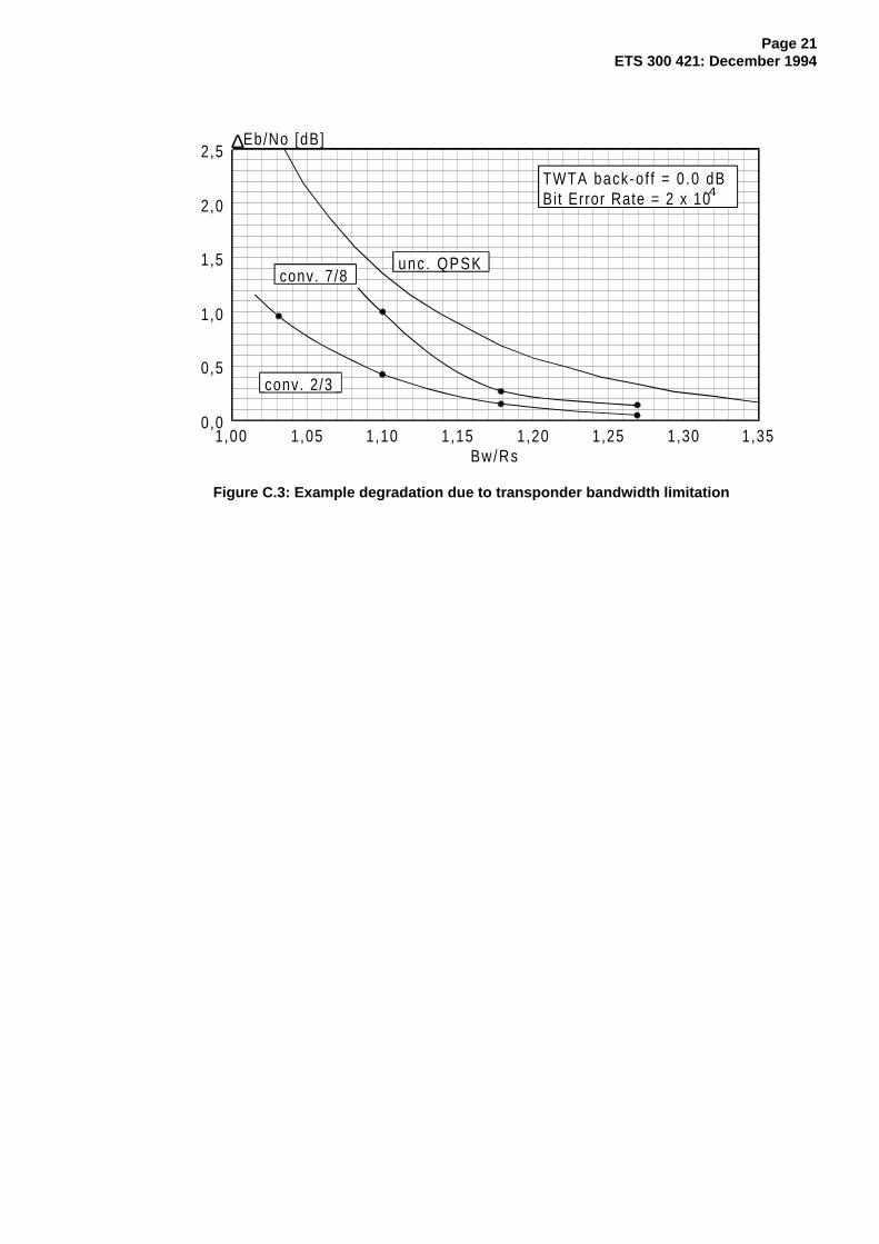
Figure C.3 gives an example of the Eb/No degradation on a computer simulated satellite transponder(Travelling Wave Tube Amplifier Output Back Off (TWTA OBO) = 0 dB) due to bandwidth limitations onIMUX and OMUX (see figures C.1 and C.2), for a ratio BW/Rs between 1 and 1,35. The reference 0 dBdegradation refers to the case of a satellite transponder without bandwidth limitations (BW = ∞, TWTAOBO = 0 dB). The results are obtained by computer simulations, with inner code rates 2/3 and 7/8, atBER = 2x10⁻⁴. Other results could be obtained for different transponder filter characteristics. When usingthe results of figure C.3, suitable margins should be allowed to take into account thermal and ageinginstabilities of the transponder characteristics.
Table C.1: Examples of bit rates versus transponder bandwidth
BW(at -3 dB)
[MHz]
BW'(at -1 dB)
[MHz]
Rs
(forBW/Rs=1.28)
[Mbaud]
Ru
(for QPSK + 1/2 convol)
[Mbit/s]
Ru
(for QPSK + 2/3 convol)
[Mbit/s]
Ru
(for QPSK +3/4 convol)
[Mbit/s]
Ru
(for QPSK + 5/6 convol)
[Mbit/s]
Ru
(for QPSK + 7/8 convol)
[Mbit/s]54 48,6 42,2 38,9 51,8 58,3 64,8 68,046 41,4 35,9 33,1 44,2 49,7 55,2 58,040 36,0 31,2 28,8 38,4 43,2 48,0 50,436 32,4 28,1 25,9 34,6 38,9 43,2 45,433 29,7 25,8 23,8 31,7 35,6 39,6 41,630 27,0 23,4 21,6 28,8 32,4 36,0 37,827 24,3 21,1 19,4 25,9 29,2 32,4 34,026 23,4 20,3 18,7 25,0 28.1 31,2 32,8
NOTE 1: Ru stands for the useful bit rate after MPEG-2 MUX. Rs (symbol rate) corresponds tothe -3dB bandwidth of the modulated signal.
NOTE 2: The figures of table C.1 correspond to an Eb/No degradation of 1,0 dB (with respect toAWGN channel) for the case of 0,35 roll-off and 2/3 code rate, including the effects ofIMUX, OMUX and TWTA.

Page 20ETS 300 421: December 1994
Ampl i tude [dB] Group delay [ns]
Frequency of fset [MHz]
0
-10
-20
-30
-40
-50
-40 -30 -20 -10 0 10 20 30 40
50
40
30
20
10
0
Figure C.1: Hypothetical IMUX filter characteristic
Ampl i tude [dB] Group delay [ns]
Frequency of fset [MHz]
0
-10
-20
-30
-40
-50
-40 -30 -20 -10 0 10 20 30 40
50
40
30
20
10
0
Figure C.2: Hypothetical OMUX filter characteristic
Page 21ETS 300 421: December 1994
Eb/No [dB]
Bw/Rs
conv. 2/3
conv. 7/8unc . QPSK
TWTA back-o f f = 0 .0 dBBit Error Rate = 2 x 10
∆
1,00 1,05 1,10 1,15 1,20 1,25 1,30 1,35
2,5
2,0
1,5
1,0
0,5
0,0
-4
Figure C.3: Example degradation due to transponder bandwidth limitation

Page 22ETS 300 421: December 1994
Annex D (informative): Examples of possible use of the System
Table D.1 considers possible examples of use of the System for a nominal transponder bandwidth (-3dB)of 33 MHz. Different inner code rates are given with the relevant bit rates.
Figure D.1 shows that the example highlighted in table D.1 with rate 2/3 inner code would be suitable forconnection to a Plesiochronous Digital Hierarchy (PDH) terrestrial network at 34,368 Mbit/s, including thesame Reed-Solomon error protection used by satellite.
Table D.1: Example of System performance over 33 MHz transponder
Bit Rate R u(after MUX)
[Mbit/s]
Bit Rate R' u(after RS)[Mbit/s]
SymbolRate
[Mbaud]
Convolut.Inner
Code Rate
RSOuter
Code Rate
C/N(33 MHz)
[dB]23,754 25,776 25,776 1/2 188/204 4,131,672 34,368 25,776 2/3 188/204 5,835,631 38,664 25,776 3/4 188/204 6,839,590 42,960 25,776 5/6 188/204 7,841,570 45,108 25,776 7/8 188/204 8,4
NOTE 1: The figures in table D.1 refer to computer simulation results achieved on a hypotheticalsatellite chain, including IMUX, TWTA and OMUX (see figures C.1 and C.2), withmodulation roll-off of 0,35. The C/N figures are based on the assumption of soft-decision Viterbi decoding in the receiver. The ratio BW/Rs = 1,28 has been adopted.
NOTE 2: The figures for C/N include a calculated degradation of 0,2 dB due to bandwidthlimitations on IMUX and OMUX filters, 0,8 dB non-linear distortion on TWTA atsaturation and 0,8 dB modem degradation. The figures apply to BER = 2x10⁻⁴ beforeRS(204,188), which corresponds to "Quasi Error Free" at the RS coder output.Degradation due to interference is not taken into account.
Video Coder
Audio Coder
Data Coder Modulator
to the RFSatellite Channel
Satellite Channel AdaptationMPEG-2: Source Coding and Multiplexing
Transport
MUX
1
2
n
Service components Services
Convolutional
Outer
Coder
RS(204,188,T=8)
Inter-leaver
InnerCoder
rate 2/3
QPSK
TerrestrialNetwork
PDHBlockCoder
RS(204,188)
34.368 Mbit/s
BlockDecoder
Terrestrial Channel Adaptation
31.672 Mbit/s
Ru=
34.368 Mbit/sR'u=
(CCITT G702)
Convol.
I=12 K=7
& Interl.
RS(204,188)
& Deint.(Hier.Level III)
Figure D.1: Example of connection of the System with the terrestrial PDH network
Page 23ETS 300 421: December 1994
Annex E (informative): Bibliography
For the purposes of this ETS, the following informative references apply:
1) DTVB 1163/GT V4/MOD 269 2nd revised version (November 1993): "Potential applications of thebaseline modulation/channel coding system for digital multi-programme television by satellite"(Contribution from V4/MOD).
2) Reimers, U. NAB'93, (EBU V4/MOD 249): "The European perspectives on Digital TelevisionBroadcasting".
3) Cominetti, M., Morello, A., Visintin; M. EBU Review - Technical, Summer '93, (EBU V4/MOD 235rev.): "Satellite digital multi-programme TV/HDTV".
4) DTVB 1110/GT V4/MOD 252/ DTVC 18, 7th revised version, January 1994: "Baselinemodulation/channel coding system for digital multi-programme television by satellite" (Contributionfrom V4/MOD-B).
5) ETS 300 429: "Digital broadcasting systems for television, sound and data services; Framingstructure, channel coding and modulation for cable systems".

Page 24ETS 300 421: December 1994
History
Document history
December 1994 First Edition
December 1995 Converted into Adobe Acrobat Portable Document Format (PDF)