european technical assessment eta-09/0227 of 2017/12/04
TRANSCRIPT

ETA-Danmark A/S Göteborg Plads 1 DK-2150 Nordhavn Tel. +45 72 24 59 00 Fax +45 72 24 59 04 Internet www.etadanmark.dk
Authorised and notified according to Article 29 of the Regulation (EU) No 305/2011 of the European Parliament and of the Council of 9 March 2011
MEMBER OF EOTA
European Technical Assessment ETA-09/0227 of 2017/12/04
General Part
Technical Assessment Body issuing the ETA and designated according to Article 29 of the Regulation (EU) No 305/2011: ETA-Danmark A/S
Trade name of the construction product:
AV Joist Hangers type A, B and Split
Product family to which the above construction product belongs:
Three-dimensional nailing plate (Joist hanger for wood to wood connections and wood to concrete or steel connections)
Manufacturer: August Vormann GmbH & Co. KG Postfach 1552 Heilenbecker Strasse 191 - 205 DE-58256 Ennepetal Tel. +49 02333 / 978 - 0 Fax +49 02333 / 978 - 241599
Internet www.vormann.com
Manufacturing plant: August Vormann GmbH & Co. KG
Berliner Strasse 50 DE-04910 Elsterwerda
This European Technical Assessment contains:
20 pages including 4 annexes which form an integral part of the document
This European Technical Assessment is issued in accordance with Regulation (EU) No 305/2011, on the basis of:
Guideline for European Technical Approval (ETAG) No. 015 Three Dimensional Nailing Plates, April 2013, used as European Assessment Document (EAD).
This version replaces:
The ETA with the same number issued on 2014-09-16

Page 2 of 20 of European Technical Assessment no. ETA-09/0227, issued on 2017-12-04
Translations of this European Technical Assessment in
other languages shall fully correspond to the original
issued document and should be identified as such.
Communication of this European Technical Assessment,
including transmission by electronic means, shall be in
full (excepted the confidential Annex(es) referred to
above). However, partial reproduction may be made, with
the written consent of the issuing Technical Assessment
Body. Any partial reproduction has to be identified as
such

Page 3 of 20 of European Technical Assessment no. ETA-09/0227, issued on 2017-12-04
II SPECIFIC PART OF THE
EUROPEAN TECHNICAL
ASSESSMENT
1 Technical description of product and
intended use
Technical description of the product
AV joist hangers type A and B are one-piece non-welded,
face-fixed joist hangers to be used in timber to timber
connections. AV joist hangers type A are also used for
connections between a timber joist and a concrete
structure or a steel member.
AV joist hangers type split are two-piece non-welded,
face-fixed joist hangers to be used in timber to timber
connections.
The joist hangers are made from pre-galvanized steel
Grade S 250 GD + Z (min Z275) according to EN
10346:2009 or from stainless steel according to EN
10088-2:2014 with Rp0,2 ≥ 240 N/mm² and Rm ≥ 500
N/mm². Dimensions, hole positions are described in
annex A.
2 Specification of the intended use in
accordance with the applicable EAD The joist hangers are intended for use in making end-grain
to side-grain connections in load bearing timber structures,
as a connection between a wood based joist and a solid
timber or wood based header, where requirements for
mechanical resistance and stability and safety in use in the
sense of the Basic Work Requirements 1 and 4 of the
Regulation 305/2011 (EU) shall be fulfilled.
The joist hangers can be installed as connections between
wood based members such as:
Structural solid timber classified to C14-C40
according to EN 338 / EN 14081,
Glulam classified to GL24-GL36 according to
EN 1194 / EN 14080,
LVL according to EN 14374,
Parallam PSL,
Intrallam LSL,
Duo- and Triobalken,
Layered wood plates,
Kreuzbalken,
I-beams with backer blocks on both sides of the web
in the header and web stiffeners in the joist,
Plywood according to EN 636.
However, the calculation methods are only allowed for a
characteristic wood density of up to 460 kg/m3. Even
though the wood based material may have a larger
density, this must not be used in the formulas for the load-
carrying capacities of the fasteners.
Annex B states the formulas for the characteristic load-
carrying capacities of the connections with joist hangers
type A and I and a table with characteristic load-carrying-
capacities of connections with joist hangers type split. The
design of the connections shall be in accordance with
Eurocode 5 or a similar national Timber Code.
It is assumed that the forces acting on the joist hanger
connection are the following Fup, Fdown and Flat, as shown
in the figure below. The forces Fup and Fdown shall act in
the middle of the joist hanger. The force Flat is assumed
to act eJ,90 above the centre of gravity of the nails in the
joist. It is assumed that the forces are acting right at the
end of the joist.
It is assumed that the header beam is prevented from
rotating. Similarly it is assumed that the concrete
structure or the steel member to which the joist hanger is
bolted does not rotate. If the header beam only has
installed a joist hanger on one side the eccentricity
moment v d H J,0M F (B / 2 e ) shall be considered.
The same applies when the header has joist hanger
connections on both sides, but with vertical forces which
differ more than 20%.
It is a condition for a force Flat perpendicular to the
vertical symmetry line that the joist hanger is connected
to a wood-based header with nails in all holes (full
nailing) or in all holes marked for partial nailing.
The joist hangers are intended for use for connections
subject to static or quasi static loading.
The zinc-coated hangers are for use in timber structures
subject to the dry, internal conditions defined by the
service classes 1 and 2 of EN 1995-1-1:2004, (Eurocode
5). The joist hangers made from stainless steel according
to EN 10088-2:2014 with Rp0,2 ≥ 240 N/mm² and Rm ≥
500 N/mm² meet the requirements of Eurocode 5 (EN
1995-1-1: 2004), for use in structures subject to the wet
conditions defined as service class 3.
The scope of the connectors regarding resistance to
corrosion shall be defined according to national
provisions that apply at the installation site considering
environmental conditions and in conjunction with the
Flat
eJ,90
Header Nail in joist Centre of grav.
B
Fup
Fdown

Page 4 of 20 of European Technical Assessment no. ETA-09/0227, issued on 2017-12-04
admissible service conditions according to EN 1995-1-1
and the admissible corrosivity category as described and
defined in EN ISO 12944-2
Assumed working life
The assumed intended working life of the joist hangers
for the intended use is 50 years, provided that they are
subject to appropriate use and maintenance.
The information on the working life should not be regarded
as a guarantee provided by the manufacturer or
ETA Danmark. An “assumed intended working life”
means that it is expected that, when this working life has
elapsed, the real working life may be, in normal use
conditions, considerably longer without major
degradation affecting the essential requirements.

Page 5 of 20 of European Technical Assessment no. ETA-09/0227, issued on 2017-12-04
3 Performance of the product and references to the methods used for its assessment
Characteristic
Assessment of characteristic
3.1 Mechanical resistance and stability (BWR 1)*)
Characteristic load-carrying capacity
See Annex B
Stiffness
No performance determined
Ductility in cyclic testing
No performance determined
3.2 Safety in case of fire (BWR 2)
Reaction to fire
The joist hangers are made from steel classified as
Euroclass A1 in accordance with EN 1350-1 and EC
decision 96/603/EC, amended by EC Decision
2000/605/EC 3.3 Hygiene, health and the environment (BWR 3)
Influence on air quality
The product does not contain/release dangerous
substances specified in TR 034, dated March 2012
3.7 Sustainable use of natural resources (BWR 7)
No Performance Determined
3.8 General aspects related to the performance
of the product
The joist hangers have been assessed as having
satisfactory durability and serviceability when used in
timber structures using the timber species described in
Eurocode 5 and subject to the conditions defined by
service class 1 and 2
Identification See Annex A
*) See additional information in section 3.9 – 3.12.
In addition to the specific clauses relating to dangerous substances contained in this European technical Assessment,
there may be other requirements applicable to the products falling within its scope (e.g. transposed European legislation
and national laws, regulations and administrative provisions). In order to meet the provisions of the Construction
Products Regulation, these requirements need also to be complied with, when and where they apply.

Page 6 of 20 of European Technical Assessment no. ETA-09/0227, issued on 2017-12-04
3.9 Methods of verification
Safety principles and partial factors
The characteristic load-carrying capacities are based on
the characteristic values of the nail connections and the
joist hangers. To obtain design values the capacities
have to be divided by different partial factors for the
material properties, the nail connection in addition
multiplied with the coefficient kmod.
According to EN 1990 (Eurocode – Basis of design)
paragraph 6.3.5 the design value of load-carrying
capacity may be determined by reducing the
characteristic values of the load-carrying capacity with
different partial factors.
Thus, the characteristic values of the load–carrying
capacity are determined also for timber failure FRk,H
(obtaining the embedment strength of nails subjected to
shear or the withdrawal capacity of the most loaded nail,
respectively) as well as for steel plate failure FRk,S. The
design value of the load–carrying capacity is the smaller
value of both load–carrying capacities.
mod Rk,H Rk,SRd
M,H M,S
k F FF min ;
Therefore, for timber failure the load duration class and
the service class are included. The different partial
factors M for steel or timber, respectively, are also
correctly taken into account.
3.10 Mechanical resistance and stability
See annex B for characteristic load-carrying capacities
of the joist hangers.
The characteristic capacities of the joist hangers are
determined by calculation assisted by testing as
described in the EOTA Guideline 015 clause 5.1.2.
They should be used for designs in accordance with
Eurocode 5 or a similar national Timber Code.
The design models allow the use of fasteners described
in the table on page 13 in Annex A:
Threaded nails (ringed shank nails) in accordance to
EN 14592
In the formulas in Annex B the capacities for threaded
nails calculated from the formulas of Eurocode 5 are
used assuming a thick steel plate when calculating the
lateral nail load-carrying-capacity.
Further, the joist hangers may be fastened to a concrete
structure or steel member by bolts with a diameter of
10 mm in holes with a diameter up to 2 mm larger than
the bolt.
The load bearing capacities of the brackets has been
determined based on the use of connector nails 4,0 x L
mm in accordance with the German national approval
for the nails.
The characteristic withdrawal capacity of the nails has
to be determined by calculation in accordance with EN
1995-1-1: 2004, paragraph 8.3.2 (head pull-through is
not relevant): Fax,Rk = fax,k × d × tpen Where: fax,k Characteristic value of the withdrawal
parameter in N/mm2 d Nail diameter in mm tpen Penetration depth of the profiles shank in mm
Based on tests by Versuchsanstalt für Stahl, Holz und
Steine, University of Kalrsruhe, the characteristic value
of the withdrawal resistance for the threaded nails used
can be calculated as: fax,k = 50 × 10-6 × σk
2 Where: σk Characteristic density of the timber in kg/m3 The shape of the nail directly under the head shall be in
the form of a truncated cone with a diameter under the
nail head which exceeds the hole diameter.
4,0 mm threaded nails with a truncated cone below the
head are used as fasteners, which are particularly
suitable for nailed steel-to-timber connections. The
specific shape below the head causes a clamping of nails
in the steel plate.
No performance has been determined in relation to
ductility of a joint under cyclic testing. The contribution
to the performance of structures in seismic zones,
therefore, has not been assessed.
No performance has been determined in relation to the
joint’s stiffness properties - to be used for the analysis
of the serviceability limit state.
3.11 Aspects related to the performance of the
product
Corrosion protection in service class 1 and 2.
In accordance with ETAG 015 the joist hanger have a
zinc coating weight of min Z275. The steel employed is
S250 GD with min Z275 according to EN
10346:2009.
The stainless steel joist hangers are made from stainless
steel according to EN 10088-2:2014 with Rp0,2 ≥ 240
N/mm² and Rm ≥ 500 N/mm².

Page 7 of 20 of European Technical Assessment no. ETA-09/0227, issued on 2017-12-04
3.12 General aspects related to the use of the
product
AV joist hangers types A, B and split are manufactured
in accordance with the provisions of this European
Technical Approval using the manufacturing processes
as identified in the inspection of the plant by the notified
inspection body and laid down in the technical
documentation.
AV Joist Hangers type A, B and Split Joist hanger connections
A joist hanger connection is deemed fit for its intended
use provided:
Header – support conditions
The header beam shall be restrained against
rotation and be free from wane under the joist
hanger.
If the header carries joists only on one side the
eccentricity moment from the joists Mec = Rjoist
(bheader/2+eJ,0) shall be considered at the strength
verification of the header.
Rjoist Reaction force from the joists
bheader Width of header
eJ,0 Distance from the centroid of the nails
in the joist to the surface of the header
For a header with joists from both sides but with
different reaction forces a similar consideration
applies.
Wood to wood connections
Joist hangers are fastened to wood-based members
by nails.
There shall be nails in all holes or a partial nailing
pattern as prescribed in Annex A-D may be used.
The characteristic capacity of the joist hanger
connection is calculated according to the
manufacturer’s technical documentation, dated
2008-09-12.
The joist hanger connection is designed in
accordance with Eurocode 5 or an appropriate
national code.
The gap between the end of the joist and the
surface, where contact stresses can occur during
loading shall be limited. This means that for joist
hangers with outward flaps the gap between the
surface of the end of the joist and that of the header
shall be maximum 3 mm.
Joist hangers with inward flaps the gap between
the surface of the nail heads in the inward flaps and
the end of the joist shall be maximum 8 mm.
For joist hangers A, B and split the width of the
joist shall be at least l+4d, where l is the length of
the fasteners and d is the fastener diameter in the
joist, for full nailing and partial nailing without
staggering the fasteners in the joist. For nailing
with staggered fasteners in the joist the width shall
be at least the penetration length of the fasteners.
The cross section of the joist at the joist hanger
connection shall have sharp edges at the lower side
against the bottom plate, i.e. it shall be without
wane.
The cross section of the header shall have a plane
surface against the whole joist hanger.
The width BJ of the joist shall correspond to that of
the joist hanger. BJ shall not be smaller than B-3
mm, where B is the inner width of the joist hanger.
The depth of the joist shall be so large that the top
of the joist is at least 20 mm above the upper
fastener in the joist.
Nails to be used shall have a diameter, which fits
the holes of the joist hangers.
Wood to concrete or steel
The above mentioned rules for wood to wood
connections are applicable also for the connection
between the joist and the joist hanger.
The joist hanger shall be in close contact with the
concrete or steel over the whole face. There shall
be no intermediate layers in between.
The gap between the end of the joist and the
surface, where contact stresses can occur during
loading shall be limited. This means that the gap
between the surface of the end of the joist and that
of the concrete or steel shall be maximum 3 mm.
The bolt shall have a diameter not less than the
hole diameter minus 2 mm.
The bolts shall be placed symmetrically about the
vertical symmetry line. There shall always be bolts
in the 2 upper holes.
The upper bolts shall have washers according to
EN ISO 7094.
Page 8 of 20 of European Technical Assessment no. ETA-09/0227, issued on 2017-12-04
4 Assessment and verification of constancy
of performance (AVCP)
4.1 AVCP system According to the decision 97/638/EC of the European
Commission1, as amended, the system(s) of assessment
and verification of constancy of performance (see
Annex V to Regulation (EU) No 305/2011) is 2+.
5 Technical details necessary for the
implementation of the AVCP system, as
foreseen in the applicable EAD Technical details necessary for the implementation of
the AVCP system are laid down in the control plan
deposited at ETA-Danmark prior to CE marking.
Issued in Copenhagen on 2017-12-04 by
Thomas Bruun
Managing Director, ETA-Danmark

Page 9 of 20 of European Technical Approval no. ETA-09/0227
Annex A
Product details and definitions
Joist hanger type A
Face mount hanger with external flanges. 2.0 mm thick pre-galvanized steel S250GD + Z (min Z275)
according to EN 10326:2004 or from stainless steel according to EN 10088-2:2014 with Rp0,2 ≥ 240
N/mm² and Rm ≥ 500 N/mm² with tolerances according to EN 10143:1993.
Partial nailing; Drawing: Blank 380, 2,0 mm steel
Blank
Total n° of
nail holes
Width
interval
Height
interval
Bolt
holes Joist hanger dimension
nH nJ min max min max n° d A e1 e2 f1 f3 f4
240 14 8 40 40 100 100 4 11 = B + 84 9 22 18 8 12
245 14 8 45 45 100 100 4 11 = B + 84 9 22 18 8 12
250 14 8 32 50 100 109 4 11 = B + 84 9 22 18 8 12
255 14 8 64 64 95 95 6 11 = B + 84 9 22 18 8 13
260 14 8 60 60 100 100 4 11 = B + 84 9 22 18 8 13
265 8 6 90 90 88 88 2 11 = B + 84 10 15 17 33 20
310 16 10 38 70 120 136 4 11 = B + 84 9 20 9 19 13
320 16 10 60 80 120 130 6 11 = B + 84 9 20 9 19 13
325 16 10 45 45 140 140 6 11 = B + 84 9 20 9 19 13
340 16 10 38 76 132 151 4 11 = B + 84 9 20 9 19 13
380 16 10 60 100 140 160 6 11 = B + 84 9 21 9 20 12,5
440 24 12 60 120 160 190 6 11 = B + 84 9 21 9 19 19
500 26 14 60 140 180 220 6 11 = B + 84 8 22 25 15 15
560 30 16 120 160 200 220 6 11 = B + 84 9 22 25 15 15
620 34 18 120 180 220 250 6 11 = B + 84 9 22 25 15 15
Joist hanger’s height = (blank – width)/2
Page 10 of 20 of European Technical Approval no. ETA-09/0227
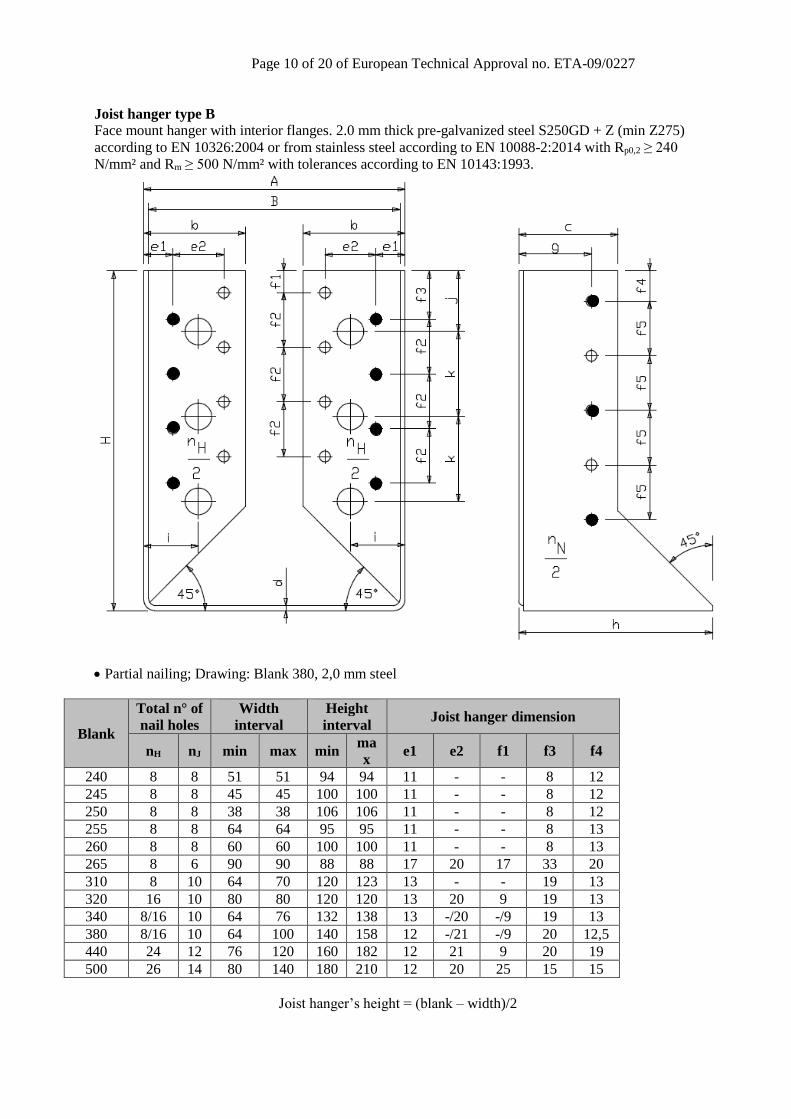
Joist hanger type B
Face mount hanger with interior flanges. 2.0 mm thick pre-galvanized steel S250GD + Z (min Z275)
according to EN 10326:2004 or from stainless steel according to EN 10088-2:2014 with Rp0,2 ≥ 240
N/mm² and Rm ≥ 500 N/mm² with tolerances according to EN 10143:1993.
Partial nailing; Drawing: Blank 380, 2,0 mm steel
Blank
Total n° of
nail holes
Width
interval
Height
interval Joist hanger dimension
nH nJ min max min ma
x e1 e2 f1 f3 f4
240 8 8 51 51 94 94 11 - - 8 12
245 8 8 45 45 100 100 11 - - 8 12
250 8 8 38 38 106 106 11 - - 8 12
255 8 8 64 64 95 95 11 - - 8 13
260 8 8 60 60 100 100 11 - - 8 13
265 8 6 90 90 88 88 17 20 17 33 20
310 8 10 64 70 120 123 13 - - 19 13
320 16 10 80 80 120 120 13 20 9 19 13
340 8/16 10 64 76 132 138 13 -/20 -/9 19 13
380 8/16 10 64 100 140 158 12 -/21 -/9 20 12,5
440 24 12 76 120 160 182 12 21 9 20 19
500 26 14 80 140 180 210 12 20 25 15 15
Joist hanger’s height = (blank – width)/2

Page 11 of 20 of European Technical Approval no. ETA-09/0227
Joist hanger type split
Face mount hanger with external flanges. 2.0 mm thick pre-galvanized steel S250GD + Z (min Z275)
according to EN 10326:2004 from stainless steel according to EN 10088-2:2014 with Rp0,2 ≥ 240
N/mm² and Rm ≥ 500 N/mm² with tolerances according to EN 10143:1993.
Drawing: Size 24 x 148, 2,0 mm steel
Size
Total n° of nail
holes
nH nJ
24 x 148 22 18
Page 12 of 20 of European Technical Approval no. ETA-09/0227
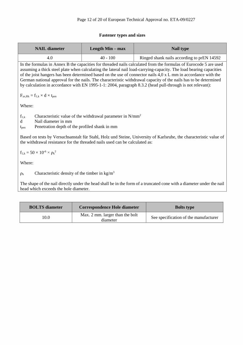
Fastener types and sizes
NAIL diameter Length Min – max Nail type
4.0 40 - 100 Ringed shank nails according to prEN 14592
In the formulas in Annex B the capacities for threaded nails calculated from the formulas of Eurocode 5 are used
assuming a thick steel plate when calculating the lateral nail load-carrying-capacity. The load bearing capacities
of the joist hangers has been determined based on the use of connector nails 4,0 x L mm in accordance with the
German national approval for the nails. The characteristic withdrawal capacity of the nails has to be determined
by calculation in accordance with EN 1995-1-1: 2004, paragraph 8.3.2 (head pull-through is not relevant):
Fax,Rk = f1,k × d × tpen
Where:
f1,k Characteristic value of the withdrawal parameter in N/mm2
d Nail diameter in mm
tpen Penetration depth of the profiled shank in mm
Based on tests by Versuchsanstalt für Stahl, Holz und Steine, University of Karlsruhe, the characteristic value of
the withdrawal resistance for the threaded nails used can be calculated as:
f1,k = 50 × 10-6 × ρk2
Where:
ρk Characteristic density of the timber in kg/m3
The shape of the nail directly under the head shall be in the form of a truncated cone with a diameter under the nail
head which exceeds the hole diameter.
BOLTS diameter Correspondence Hole diameter Bolts type
10.0 Max. 2 mm. larger than the bolt
diameter See specification of the manufacturer

Page 13 of 20 of European Technical Approval no. ETA-09/0227
Annex B
Characteristic values of load-carrying-capacities
Characteristic capacities of the joist hanger connections with nails only
The downward and the upward directed forces are assumed to act in the middle of the joist. The lateral force is assumed
to act at an distance eJ,90 above the centre of gravity of the nails in the joist.
Two nails patterns are specified. A full nailing pattern, where there are nails in all the holes and a partial nailing
pattern, where the number of nails in the joist and the header are at least half the numbers specified for full nailing.
The nails in the joist may be staggered. The nails in the header shall be put in the holes closest to the bend line.
For AV joist hangers the width of the joist shall be at least l+4d, where l is the length of the nails and d is the diameter
of the nails in the joist, for full nailing and partial nailing without staggering the nails in the joist. For partial nailing
with staggered nails in the joist the width shall be at least the penetration length of the nails.
B.1 Joist hangers types A and B fastened with nails
Force downward toward the bottom plate:
J v,J,Rd
2 2Z,Rd
H v,H,Rd H,1 ax,H,Rd
(n 2) F
1F = min
1 1 +
n F k F
(B.1.1.1)
Force upward away from the bottom plate:
J v,J,Rd
2 2Z,Rd
H v,H,Rd H,2 ax,H,Rd
n F
1F = min
1 1 +
n F k F
(B.1.1.2)
Lateral force:
J v,J,Rd
222 2J,0 J,90 v,J,Rd
J ax,J,Rd
Y,Rd
v,H,Rd
22
H H
H 1 2
n F
2 e e F
b FF = min
F
e e1
n e e
(B.1.1.3)
nJ total number of nails in both sides of the joist
nH total number of nails in the side of the header
Fv,Rd Characteristic lateral load-carrying capacity of the fasteners in the joist or in the header indicated by the indices J
or H
Fax,Rd Characteristic axial load-carrying capacity of the fasteners in the joist or in the header indicated by the indices J or
H
bJ width of the joist hanger, see figure B1.
eJ,90 distance of the lateral force above the centre of gravity of the nails in the joist, see figure B1.
eJ,0 distance from the nails in the joist to the surface of the header, see figure B1.
eH distance of the lateral force above the centre of gravity of the nails in the header.
e1 joist hanger dimension, see Annex C
e2 joist hanger dimension, see Annex C
kH,1 form factor, see Annex C

Page 14 of 20 of European Technical Approval no. ETA-09/0227
kH,2 form factor, see Annex C
Figure B1: Definition of eJ,90 and eJ,0
B.1.2 Combined forces
In case of combined forces shall the following inequality be fulfilled:
2 2
Y,Ed Z,Ed
Y,Rd Z,Rd
F F1
F F
(B.1.2.1)
B.2 One pair of joist hangers type split fastened with nails
Type
Force downward towards to or upward away from the bottom plate
FZ,Rk [kN]
Lateral Force
FY,Rk [kN]
Timber Timber Steel
24 x 148 24,1 9,70 8,53
For timber or wood based material with a lower characteristic density than 350 kg/m3 the load-carrying capacities
shall be reduced by the kdens factor:
2
k
densk
350
where ρk is the characteristic density of the timber in kg/m3.
B.2.2 Combined forces
If the forces FY,Ed and FZ,Ed act at the same time or if eH 0, the following inequality shall be fulfilled:
2 2
Y,Ed Z,Ed Z,Ed
Y,Rd Z,Rd
F F 2 F1
F F
(B.2.1)
Where:
HZ,Ed Y,Ed
eF F
B (B.2.2)
FY,Ed
eJ,90
Header Nail in joist Centre of grav.
bJ FZ,Ed,up
FZ,Ed,down
FY,Ed
eJ,0

Page 15 of 20 of European Technical Approval no. ETA-09/0227
B.3 Characteristic capacities of the joist hanger type A connections with bolts
For joist hangers type A connected to a wall of concrete, lightweight concrete or to a steel member the assumptions for
the calculation of the load-carrying capacity of the connection are:
The transfer of force from the joist to the joist hanger is as for a wood-wood connection, see clause B.1;
The bolts shall always be positioned symmetrically about the vertical axis of the joist hanger;
Washers according to EN ISO 7094 shall be installed at least under the upper 2 bolt heads or nuts.
Description of the static model
For a downward directed force toward the bottom plate the static behavior is basically the same as for a wood-wood
connection with nails.
The nails in the joist are subjected to a lateral force, which is equally distributed over all nails in the joist.
Since the concrete and steel have a larger compressive strength than timber subjected perpendicular to the grain the
rotation point may be assumed positioned at the top of the bottom plate.
Figure B2 Left: Cross section in joist. Right: The joist will deflect and rotate, at the bottom a contact force will
occur at the bottom plate, and the withdrawal forces in the bolts in the wall will vary linearly as assumed
for nailed connections in the header.
The forces in the bolts will be partly lateral forces, partly withdrawal forces. The lateral forces are distributed evenly
over all bolts. The withdrawal forces are on the safe side assumed to be taken by the 2 upper bolts with washers. The
maximum withdrawal force in a upper bolt can be calculated from
J,0
ax,bolt
max
F eF
2 z
(B.3.1)
Where
F downward directed force toward the bottom plate;
eJ,0 eccentricity = distance from the nail column in the joist to the surface of the header;
zmax max distance from upper bolt to the bottom plate (rotation point).
The upper 2 bolts are critical. They are subjected to a lateral force and a withdrawal force. The lateral force is determined
assuming an even distribution of the downward force F.
lat,bolt boltF F/ n (B.3.2)
Characteristic capacities of a bolted joist hanger connection
The Characteristic capacity of the connection between the joist and the joist hanger may be calculated from the same
assumptions and formulas as for joist hangers nailed to a wooden header beam.
Nail force Contact force
Force Downward, F
Washer According to ISO 7094
zmax

Page 16 of 20 of European Technical Approval no. ETA-09/0227
Z,Rk J v,J,RkF = (n 2) F for threaded nails (B.3.3)
The upper 2 bolts are critical. They are subjected to a lateral force calculated from formula (B.3.2).
The withdrawal force in an upper bolt is calculated from (B.3.1).
Where
F downward directed force toward the bottom plate
nbolt total number of bolts in the joist hanger
eJ,0 eccentricity = distance from the nail column in the joist to the surface of the header
zmax max distance from the upper bolt to the bottom plate (rotation point)
It shall be verified by the design of the bolted connection that the upper bolts have sufficient load-carrying capacity to
carry the combined lateral and axial forces.
From the Characteristic load-carrying-capacity of the bearing resistance between the bolt and the plate of the joist hanger
the following maximum characteristic capacity of the joist hanger connection can be determined.
bear,Rk bolt u,kF n f d t (B.3.4)
where
nbolt total number of bolts in the 2 flaps
fu,k characteristic ultimate tensile strength of the steel
d diameter of the bolt
t thickness of the steel plate of the joist hanger
The characteristic load-carrying capacity of the joist hanger connections is the minimum of:
The capacity determined from (B.3.3) from the fasteners in the joist;
The capacity determined from (B.3.4) from the embedding strength of the steel plate against the bolt;
The capacity controlled by the bolt forces given by (B.3.1) and (B.3.2).

Page 17 of 20 of European Technical Approval no. ETA-09/0227
Annex C
Form factors kH,1 and kH,2 and dimensions e1, e2 and eJ,0
Table C1: AV Joist hanger type A with external flanges:
Form factors kH,1 and kH,2 and dimensions e1, e2 and eJ,0
B
[mm]
H
[mm] nH nJ kH,1 kH,2
e1
[mm]
e2
[mm]
eJ,0
[mm] nH nJ kH,1 kH,2
e1
[mm]
e2
[mm]
eJ,0
[mm]
Full nailing Partial nailing
40 100 14 8 17,1 7,16 1005 569 31 8 4 10,1 4,41 390 377 31
45 100 14 8 17,1 7,16 1102 596 31 8 4 10,1 4,41 433 387 31
32 109 14 8 20,5 6,45 861 527 31 8 4 12,0 3,97 328 364 31
38 106 14 8 19,3 6,67 967 558 31 8 4 11,3 4,11 373 373 31
50 100 14 8 17,1 7,16 1205 623 31 8 4 10,1 4,41 479 399 31
60 100 14 8 17,7 7,40 1429 680 30 8 4 10,4 4,55 582 426 30
64 95 14 8 15,8 7,88 1525 704 30 8 4 9,38 4,85 626 437 30
38 136 16 10 32,0 7,72 1092 735 31 8 6 17,8 3,09 348 381 31
50 130 16 10 29,3 8,14 1339 808 31 8 6 16,4 3,25 444 409 31
70 120 16 10 24,9 8,94 1824 939 31 8 6 14,2 3,58 641 467 31
45 140 16 10 33,8 7,46 1232 777 31 8 6 18,7 2,99 402 397 31
60 130 16 10 29,3 8,14 1570 872 31 8 6 16,4 3,25 537 437 31
80 120 16 10 24,9 8,94 2100 1007 31 8 6 14,2 3,58 756 499 31
38 151 16 10 38,8 6,84 1092 735 31 8 6 21,3 2,74 348 381 31
60 140 16 10 33,8 7,46 1570 872 31 8 6 18,7 2,99 537 437 31
64 138 16 10 32,9 7,59 1669 898 31 8 6 18,3 3,04 577 449 31
70 135 16 10 31,5 7,79 1824 939 31 8 6 17,6 3,11 641 467 31
76 132 16 10 30,2 7,99 1987 979 31 8 6 16,9 3,20 709 486 31
60 160 16 10 41,6 8,38 1435 897 30 8 6 23,0 3,35 487 457 30
64 158 16 10 40,6 8,50 1522 922 30 8 6 22,5 3,40 522 467 30
70 155 16 10 39,2 8,69 1658 960 30 8 6 21,7 3,47 577 484 30
76 152 16 10 37,8 8,88 1802 999 30 8 6 21,0 3,55 637 501 30
80 150 16 10 36,9 9,02 1902 1026 30 8 6 20,5 3,61 678 513 30
90 145 16 10 34,6 9,38 2166 1094 30 8 6 19,4 3,75 789 545 30
100 140 16 10 32,3 9,76 2451 1163 30 8 6 18,2 3,90 910 578 30
60 190 24 12 64,2 18,5 1771 1546 32 12 6 34,7 8,04 639 837 32
70 185 24 12 61,1 19,1 2011 1626 32 12 6 33,0 8,28 737 862 32
76 182 24 12 59,2 19,4 2165 1677 32 12 6 32,1 8,44 778 874 32
80 180 24 12 57,9 19,6 2273 1712 32 12 6 31,4 8,54 845 893 32
100 170 24 12 51,7 20,9 2862 1896 32 12 6 28,2 9,11 1093 970 32
116 162 24 12 46,9 22,1 3396 2052 32 12 6 25,7 9,62 1324 1040 32
120 160 24 12 45,7 22,4 3538 2092 32 12 6 25,1 9,75 1386 1058 32
60 220 26 14 81,8 20,8 1837 1723 32 14 8 44,5 11,7 785 1121 32
76 212 26 14 76,2 21,7 2227 1856 32 14 8 41,5 12,2 957 1148 32
80 210 26 14 74,8 22,0 2333 1891 32 14 8 40,7 12,3 1004 1159 32
100 200 26 14 67,9 23,2 2915 2082 32 14 8 37,1 13,0 1270 1229 32
120 190 26 14 61,2 24,6 3583 2287 32 14 8 33,5 13,8 1583 1319 32
140 180 26 14 54,6 26,2 4339 2503 32 14 8 30,0 14,7 1942 1421 32
120 220 30 16 86,8 33,6 3682 2771 31 16 8 46,9 18,5 1632 1609 31
140 210 30 16 78,9 35,4 4421 3005 31 16 8 42,8 19,5 1980 1711 31
160 200 30 16 71,3 37,4 5247 3250 31 16 8 38,7 20,6 2373 1825 31
120 250 34 18 118 44,3 3884 3341 30 18 10 63,2 24,2 1734 1954 30
140 240 34 18 109 46,4 4618 3587 30 18 10 58,3 25,3 2076 2051 30

Page 18 of 20 of European Technical Approval no. ETA-09/0227
Table C1 (contd.): AV Joist hanger type A with external flanges:
Form factors kH,1 and kH,2 and dimensions e1, e2 and eJ,0
Table C2: Joist hanger type B with interior flanges:
Form factors kH,1 and kH,2 and dimensions e1, e2 and eJ,0
B
[mm]
H
[mm] nH nJ kH,1 kH,2
e1
[mm]
e2
[mm]
eJ,0
[mm] nH nJ kH,1 kH,2
e1
[mm]
e2
[mm]
eJ,0
[mm]
Full nailing Partial nailing
160 230 34 18 99,7 48,7 5437 3849 30 18 10 53,5 26,5 2463 2165 30
180 220 34 18 90,8 51,1 6341 4124 30 18 10 48,9 27,9 2895 2293 30
90 88 8 6 9,57 0,86 3311 516 34 4 4 5,54 0,25 1303 252 34
B
[mm]
H
[mm] nH nJ kH,1 kH,2
e1
[mm]
e2
[mm]
eJ,0
[mm] nH nJ kH,1 kH,2
e1
[mm]
e2
[mm]
eJ,0
[mm]
Full nailing Partial nailing
45 100 8 8 10,1 4,41 156 404 31 8 4 10,1 4,41 156 404 31
38 106 8 8 11,3 4,11 137 480 31 8 4 11,3 4,11 137 480 31
51 94 8 8 8,88 4,75 177 374 31 8 4 8,88 4,75 177 374 31
60 100 8 8 10,4 4,55 215 358 30 8 4 10,4 4,55 215 358 30
64 95 8 8 9,38 4,85 235 358 30 8 4 9,38 4,85 235 358 30
64 123 8 10 12,6 3,84 215 358 31 8 6 12,6 3,84 215 358 31
70 120 8 10 12,0 3,97 246 359 31 8 6 12,0 3,97 246 359 31
80 120 16 10 24,9 8,94 451 544 31 8 6 14,2 3,58 307 370 31
64 138 8 10 16,0 3,31 215 358 31 8 6 16,0 3,31 215 358 31
70 135 8 10 15,3 3,41 246 359 31 8 6 15,3 3,41 246 359 31
76 132 16 10 30,2 7,99 418 542 31 8 6 16,9 3,20 281 364 31
64 158 8 10 20,1 3,66 218 409 30 8 6 20,1 3,66 218 409 30
70 155 8 10 19,1 3,78 256 403 30 8 6 19,1 3,78 256 403 30
76 152 16 10 38,3 8,66 437 614 30 8 6 21,0 3,55 288 405 30
100 140 16 10 32,7 9,52 666 655 30 8 6 18,2 3,90 454 447 30
76 182 24 12 59,2 19,4 702 1378 32 12 6 32,1 8,44 426 836 32
80 180 24 12 57,9 19,6 734 1346 32 12 6 31,4 8,54 451 827 32
100 170 24 12 51,7 20,9 948 1303 32 12 6 28,2 9,11 604 830 32
120 160 24 12 45,7 22,4 1249 1374 32 12 6 25,1 9,75 800 880 32
80 210 26 14 72,0 22,4 833 1666 32 14 8 39,3 12,6 583 1167 32
100 200 26 14 67,9 23,2 1060 1590 32 14 8 37,1 13,0 747 1120 32
120 190 26 14 61,2 24,6 1370 1644 32 14 8 33,5 13,8 957 1148 32
140 180 26 14 54,6 26,2 1767 1767 32 14 8 30,0 14,7 1213 1213 32
90 88 8 6 7,26 2,78 260 208 34 4 4 4,40 0,99 193 154 34

Page 19 of 20 of European Technical Approval no. ETA-09/0227
Annex D
Installation of joist hangers
Joist hanger in wood/wood connection
3 mm
4 x d
4 x d
s
HeaderJoist Joist
Header
BJ
BH
HH
HH
J
a
Joist

Page 20 of 20 of European Technical Approval no. ETA-09/0227
Joist hanger connected to concrete, lightweight concrete
or a steel member by bolts
Joist
Header
B
H
Joist
Joist
A
3 mm 3 mm
J
Concrete
Bolts M10
Washer according to
EN ISO 7094