evaluation of necessity of off-gas scrubber for v-tanks
TRANSCRIPT

Document ID: EDF-5905Revision ID: 0
Effective Date: 07-06-05
Engineering Design File
Project No: 22901
Evaluation of Necessity of Off-Gas Scrubber for V-Tanks Treatment Process

431.02 01/30/2003 Rev. 11
ENGINEERING DESIGN FILE
EDF No.: 5905 EDF Rev. No.: 0 Project File No.: 22901
1. Title: EVALUATION OF NECESSITY OF OFF-GAS SCRUBBER FOR V-TANKS TREATMENT PROCESS
2. Index Codes: Building/Type WAG 1 SSC ID N/A Site Area TAN
3. NPH Performance Category: or N/A
4. EDF Safety Category: or N/A SCC Safety Category: N/A or N/A
5. Summary: The option of not using the venture/packed bed scrubber on the V-Tank Project consolidation tank sparging off-gas treatment was evaluated. In lieu of the scrubber, in-line vent demisters would be installed. However, the radiation fields background and on the HEPA filter, are still low. It is recommended to use the in-line demisters. Also, no additional isolation for the HEPA filters is required. This assessment is limited in application to sparging and consolidation type operations. If chemical oxidation or boiling conditions are deployed as part of the conditional Phase 2 operations then the necessity of the scrubber should be revisited.
6. Review (R) and Approval (A) and Acceptance (Ac) Signatures: (See instructions for definitions of terms and significance of signatures.)
R/A Typed Name/Organization Signature Date Performer/ Author N/A S.C. Ashworth S.C. Ashworth, via e-mail 06/06/05 Technical Checker R D.R. Tyson D.R. Tyson, via e-mail 06/09/05 Independent Peer Reviewer (if applicable) R Approver A D.F. Nickelson D.F. Nickelson , via e-mail 06/06/05 Requestor (if applicable) Ac D.L. Eaton D.L. Eaton, via e-mail 06/09/05
Reviewer R R. Sorensen R. Sorensen, via e-mail 06/09/05
Reviewer R M. Bodily M. Bodily, via e-mail 06/13/05
Doc. Control 7. Distribution:
(Name and Mail Stop) S.C.Ashworth 3670, M.E. Bodily 3650, D.F. Nickelson 3670, D.L. Eaton, D.R. Tyson 9206, J.J. Jessmore 9206, R. Sorensen 9208
8. Does document contain sensitive unclassified information? Yes No If Yes, what category: 9. Can document be externally distributed? x Yes No 10. Uniform File Code: Disposition Authority: Record Retention Period: 11. For QA Records Classification Only: Lifetime Nonpermanent Permanent Item and activity to which the QA Record apply: 12. NRC related? Yes No


431.02 01/30/2003 Rev. 11
ENGINEERING DESIGN FILE EDF-5905Revision 0
Page 5 of 27
MW Molecular weight, g/mol
n Pressure loss parameter
ns Separation number
ppmv Parts per million, volume basis
P Radionuclide particle power/unit mass, J/kg/s, pressure
Q Flow, ft3/min or gpm, quality factor
r Rate, nCi/min
Rad 100 erg/g
Re Reynolds number
Rg Gas constant, L-atm/mol/°K
t Time, t
T Temperature, °K
v Velocity, ft/s
V Volume, ft3
W Weight, kg
y Gas concentration, Ci/L
z Height, ft
431.02 01/30/2003 Rev. 11
ENGINEERING DESIGN FILE EDF-5905Revision 0
Page 6 of 27
GREEK
ε Void fraction
η Efficiency
λ Droplet mean free path, µm
µ Viscosity, lbm/ft/s
µm Micro meter (micron)
ф Shape factor
ρ Density, kg/L
431.02 01/30/2003 Rev. 11
ENGINEERING DESIGN FILE EDF-5905Revision 0
Page 7 of 27
1. INTRODUCTION
1.1 Background
The Test Area North (TAN) V-Tanks project provided a design for air stripping volatile organic compounds (VOCs) from the waste solutions in the V-Tanks. The design was based on transferring the V-Tank contents to consolidation tanks followed by air-stripping (sparging) using specially designed consolidation tank features as discussed in a previous EDF-4956 (Ashworth 2004). At the time, a post-sparging Fenton process by AEA Technologies (AEA) was planned that required a venturi-packed bed scrubber system (Severn-Trent). The project direction was to flow the sparge air and Fenton off-gas through the scrubber process prior to treatment by other off-gas components (e.g., HEPA and GAC). Since then, approval was given to conduct initial operations, such as sparge only and not operate the Fenton process (DOE 2005). Some of the options for scrubber operation were discussed in EDF-4956 per project request. It was found that the scrubber could either be bypassed or operated with modifications. In lieu of the scrubber, it is recommended that a demister unit would be utilized prior to the HEPA and GAC bed.
If Phase 2 treatment operations are determined to be necessary which employ either chemical oxidation and/or boiling conditions, then the necessity of the scrubber to control radioactive off-gas emissions should be revisited.
2. Scope
This EDF is to provide a basis for bypassing the scrubber in the system and replacing it with a demister. In addition, it provides a basis for not installing isolation valves around the HEPA.
3. SAFETY CATEGORY
Consumer Grade.
4. NATURAL HAZARDS PHENOMENA PERFORMANCE CATEGORY
N/A
5. SUBJECT-SPECIFIC DATA
The Appendix B provides for approximate radiation fields as a result of replacing the scrubber with in-line demisters and includes most of the analysis. Per the scope, this EDF addresses the following three issues:
5.1 Scrubber Requirement
The reason for the scrubber was to remove particles with a high degree of efficiency from vapors emitted by the Fenton process, operated at or near the boiling point. It is not clear from their basis but the vendors apparently assumed a large entrainment from the process. The basis is not documented. They also used a removal efficiency of 99.99% for particles in their vendor data. While it is believed that units like this would be desirable for off-gas systems used in treating highly radioactive solutions to reduce the radiation fields in downstream HEPAs, they are usually not specified for low level wastes such as the
431.02 01/30/2003 Rev. 11
ENGINEERING DESIGN FILE EDF-5905Revision 0
Page 8 of 27
V-Tanks. Much of this is based on experience but it can also be documented as in the radiation field calculations provided in Appendix B. The scrubber system for processing the V-tank waste is not required based on the estimates in Appendix B and the fact that the boiling conditions or Fenton-type reaction system will not be used in this phase of treatment operations.
5.2 In-Line Demister
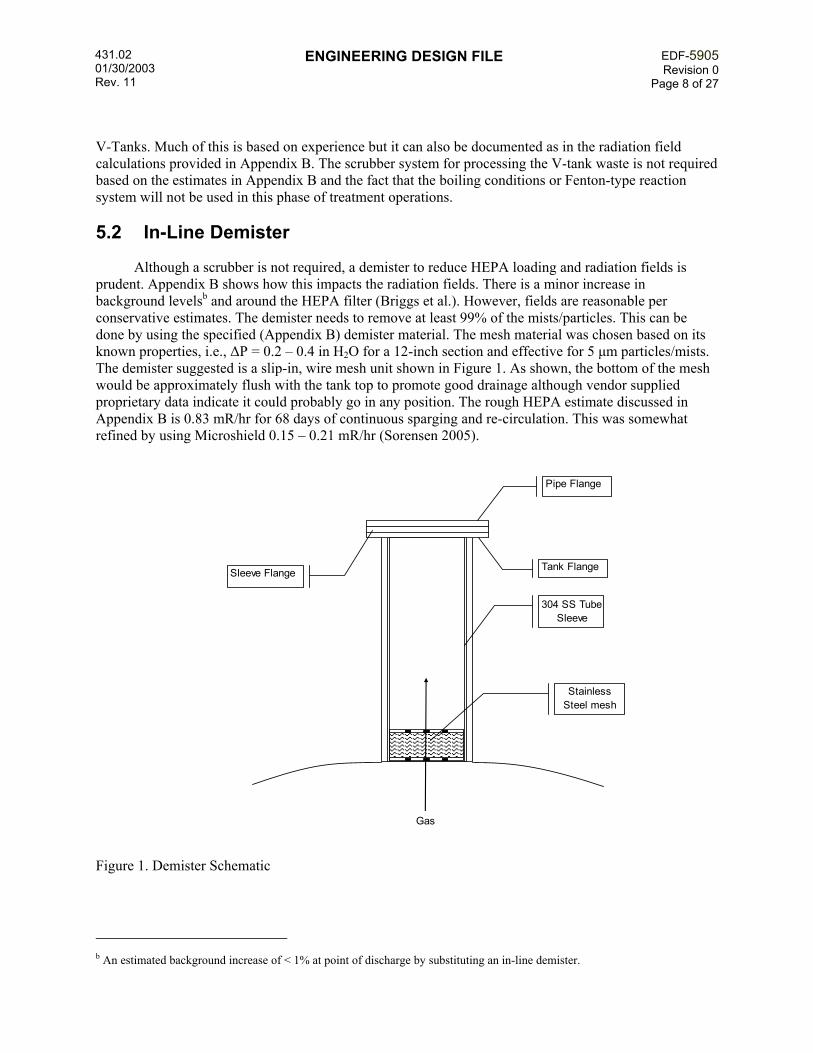
Although a scrubber is not required, a demister to reduce HEPA loading and radiation fields is prudent. Appendix B shows how this impacts the radiation fields. There is a minor increase in background levelsb and around the HEPA filter (Briggs et al.). However, fields are reasonable per conservative estimates. The demister needs to remove at least 99% of the mists/particles. This can be done by using the specified (Appendix B) demister material. The mesh material was chosen based on its known properties, i.e., ∆P = 0.2 – 0.4 in H2O for a 12-inch section and effective for 5 µm particles/mists. The demister suggested is a slip-in, wire mesh unit shown in Figure 1. As shown, the bottom of the mesh would be approximately flush with the tank top to promote good drainage although vendor supplied proprietary data indicate it could probably go in any position. The rough HEPA estimate discussed in Appendix B is 0.83 mR/hr for 68 days of continuous sparging and re-circulation. This was somewhat refined by using Microshield 0.15 – 0.21 mR/hr (Sorensen 2005).
Pipe Flange
Tank FlangeSleeve Flange
Gas
Stainless Steel mesh
304 SS Tube Sleeve
Figure 1. Demister Schematic
b An estimated background increase of < 1% at point of discharge by substituting an in-line demister.

431.02 01/30/2003 Rev. 11
ENGINEERING DESIGN FILE EDF-5905Revision 0
Page 9 of 27
5.3 HEPA Isolation
Due to low radiation fields predicted from use of an upstream demister, the currently available, upstream valves are sufficient to isolate the HEPA in the unexpected event of a changeout. Air-sparging and active off gas system operations will need to suspended during HEPA changeout which is acceptable from a process/technical and functional requirements perspective since the solids can be re-suspended by re-circulation pumping and the agitator.
6. ASSUMPTIONS
• There are two major entrainment mechanisms included, one via air sparging (40 cfm of air) and the other via splashing from re-circulation liquid (100 gpm of re-circulating liquid introduced at a height of three feet above the tank liquid).
• The entrained aerosols/mists have a particle distribution that 95% > 5µm by mass. This is uncertain as the distribution was not determined.
• Others as stated in calculations (Appendix B).
7. ACCEPTANCE CRITERIA
The change in design (a custom in-line demister to replace the current scrubber) leads to acceptable radiation fields and is protective of the HEPA filter.
8. SOFTWARE
The following industry-wide software, requiring no validation, was used for this EDF:
• MathCad Version 11.
• EXCEL Version 2003.
9. CALCULATIONS
See Appendix B.
10. CONCLUSIONS
In general, by replacing the current scrubber with a custom in-line demister, the background levels at the stack point of discharge may increase (<1% estimated). The radiation field at the HEPA surface is expected to increase slightly but still meet ALARA goals. The HEPA filter is protected from particles and mists greater than 5 µm in diameter and most of those less than 5 µm. The HEPA does not require additional isolation for change-out. While it is possible to fabricate a demister mesh, a vendor specified mesh/packing is preferred to minimize pressure loss while obtaining the needed efficiency, i.e., the media specified in Appendix B has known pressure loss and efficiency. No additional HEPA isolation is required.
431.02 01/30/2003 Rev. 11
ENGINEERING DESIGN FILE EDF-5905Revision 0
Page 10 of 27
11. RECOMMENDATIONS
It is recommended to use an in-line demister if the scrubber is not used. This demister should be a vendor supplied mesh/packing as discussed in Appendix B and welded or otherwise attached to the bottom of a sleeve or tube inside the flanged vent penetration as shown in Figure 1. Appendix B provides a specification. Provide no additional HEPA isolation than that already provided by the upstream valves. If Phase 2 treatment operations are determined to be necessary at elevated temperatures or using the Fenton reaction, then the requirement for the scrubber should be reevaluated.
12. REFERENCES
Ashworth 2004, S.C., Lopez, D.A., Design for VOC Control for the TSF-09/18 V-Tank Remedial Action, EDF-4956, REV. 1, 11/17/2004.
Ballinger, M.Y., Review of Grout Particulate-Emissions Methodology, Internal Letter – PNL to Westinghouse Hanford, PNL-8643, September 1993.
Ballinger, M.Y., Personal conversation – Sam Ashworth, CH2M-WG Idaho with Marcel Ballinger, Battelle, email and telecoms, 6/05.
Baum, E.M., Knox, H.D., Miller, T.R., Nuclides and Isotopes, 16th ed., Knolls Atomic Power Laboratory, 2002.
Briggs, C., Gesell, T., Variations in Penetrating Background Radiation Doses On and Around the INEEL, INEEL Oversight Program.
DOE 1994, DOE Handbook, Airborne Release Fractions/Rates and Respirable Fractions for Nunreactor Nuclear Facilities, Vol. 1, Analysis of Experimental Data, DOE-HDBK-3010-94, December 1994.
DOE 2005, Explanation of Significant Differences for the Record of Decision for the Test Area North Operable Unit 1-10, DOE/NE-ID-11199 January 2005 Rev. 0.
Kreith, F., Principles of Heat Transfer, 3rd ed., Intext Educational Publishers, 1973.
Perry, R.H., D. W. Green, Perry's Chemical Engineers' Handbook, 6th ed., McGraw-Hill 1984.
PNNL 2004, Bamberger, J.A., Glissmeyer, J.A., Release Fraction Evaluation, PNNL-14545, January 2004.
Sorensen, R, email to design/projects team, 6/1/2005.
Tyson D.R., EDF-3868, V-Tank Analytical Data: Calculated Averages and Upper Confidence Limits, Rev. 1, 12/08/03.
Tyson, D. R., EDF-4928, Potential Feed Streams for Inclusion into V-Tank Treatment Process, Rev 0., 9/9/04.
Yapyuco, B., Stainless Steel Woven Fabric Cloth Co., telecom, Sam Ashworth with Ben Yapyuco, June 3, 2005.

431.02 01/30/2003 Rev. 11
ENGINEERING DESIGN FILE EDF-5905Revision 0
Page 11 of 27
Appendix A – Task Planning Documentation
Add on TBA for Project 22901
431.02 01/30/2003 Rev. 11
ENGINEERING DESIGN FILE EDF-5905Revision 0
Page 12 of 27
This page intentionally left blank
431.02 01/30/2003 Rev. 11
ENGINEERING DESIGN FILE EDF-5905Revision 0
Page 13 of 27
Appendix B – Calculations

431.02 01/30/2003 Rev. 11
ENGINEERING DESIGN FILE EDF-5905Revision 0
Page 14 of 27
This page intentionally left blank
431.02 01/30/2003 Rev. 11
ENGINEERING DESIGN FILE EDF-5905Revision 0
Page 15 of 27
Appendix B, Supporting Calculations
Contents I. Data II. Characterization III. Entrained Radionuclides and Loadings IV. Demister Mesh Design
I. Data. The data below are used in the Estimates
P12.514.7
atm:= Tg 298K:= Rg 0.082L atm⋅
mol K⋅:=
ρH2O 1kgL
:= MWair 29gmmol
:=
Qs 40ft3
min:= Sparge nominal rate and time t s 42 hr:=
Dtk 10ft:= Atkπ
4Dtk
2⋅:=
Liquid viscosity, the factor of 2 is to account for solids Vapor viscosity (both viscosities from Kreith, Kreith 1973)
µL 0.658 10 3−⋅
lbft s⋅
2⋅:= µg 1.2 10 5−⋅
lbft s⋅
:=
Vapor and liquid densities (assume 1 for liquid because of the uncertainties in other data).
ρgP MWair⋅
Rg Tg⋅:= ρL 1
kgL
:=
The tank vapor, superficial velocity: vtkQsAtk
:=
431.02 01/30/2003 Rev. 11
ENGINEERING DESIGN FILE EDF-5905Revision 0
Page 16 of 27
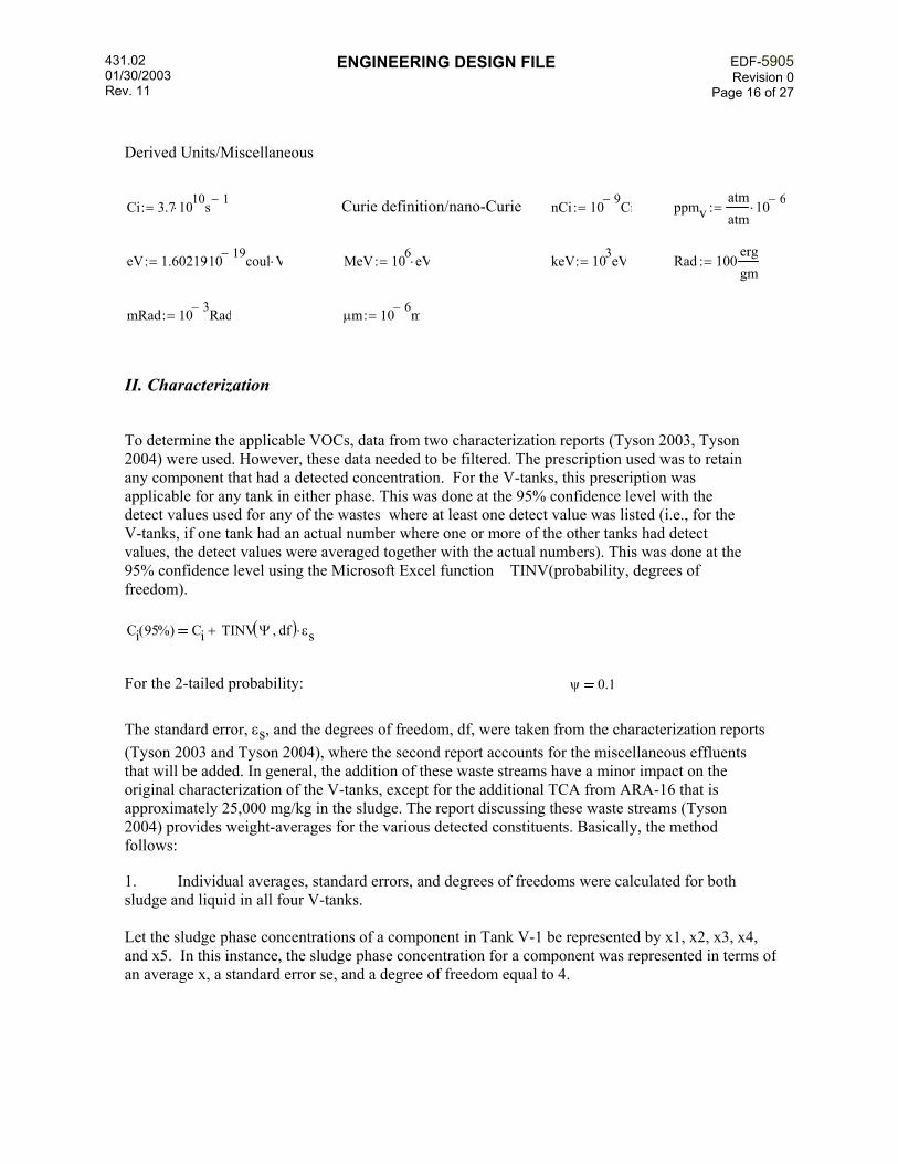
Derived Units/Miscellaneous
Ci 3.7 1010⋅ s 1−
:= Curie definition/nano-Curie nCi 10 9− Ci:= ppmvatmatm
10 6−⋅:=
eV 1.6021910 19−⋅ coul V⋅:= MeV 106 eV⋅:= keV 103eV:= Rad 100
erggm
:=
mRad 10 3− Rad:= µm 10 6− m:=
II. Characterization
To determine the applicable VOCs, data from two characterization reports (Tyson 2003, Tyson 2004) were used. However, these data needed to be filtered. The prescription used was to retain any component that had a detected concentration. For the V-tanks, this prescription was applicable for any tank in either phase. This was done at the 95% confidence level with the detect values used for any of the wastes where at least one detect value was listed (i.e., for the V-tanks, if one tank had an actual number where one or more of the other tanks had detect values, the detect values were averaged together with the actual numbers). This was done at the 95% confidence level using the Microsoft Excel function TINV(probability, degrees of freedom).
Ci 95%( ) Ci TINV Ψ df,( ) εs⋅+
For the 2-tailed probability: ψ 0.1
The standard error, εs, and the degrees of freedom, df, were taken from the characterization reports (Tyson 2003 and Tyson 2004), where the second report accounts for the miscellaneous effluents that will be added. In general, the addition of these waste streams have a minor impact on the original characterization of the V-tanks, except for the additional TCA from ARA-16 that is approximately 25,000 mg/kg in the sludge. The report discussing these waste streams (Tyson 2004) provides weight-averages for the various detected constituents. Basically, the method follows:
1. Individual averages, standard errors, and degrees of freedoms were calculated for both sludge and liquid in all four V-tanks. Let the sludge phase concentrations of a component in Tank V-1 be represented by x1, x2, x3, x4, and x5. In this instance, the sludge phase concentration for a component was represented in terms of an average x, a standard error se, and a degree of freedom equal to 4.

431.02 01/30/2003 Rev. 11
ENGINEERING DESIGN FILE EDF-5905Revision 0
Page 17 of 27
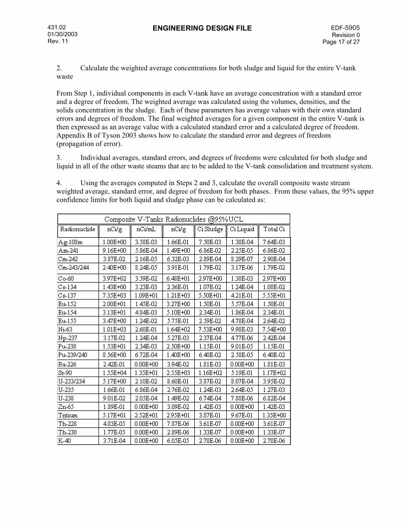
2. Calculate the weighted average concentrations for both sludge and liquid for the entire V-tank waste From Step 1, individual components in each V-tank have an average concentration with a standard error and a degree of freedom. The weighted average was calculated using the volumes, densities, and the solids concentration in the sludge. Each of these parameters has average values with their own standard errors and degrees of freedom. The final weighted averages for a given component in the entire V-tank is then expressed as an average value with a calculated standard error and a calculated degree of freedom. Appendix B of Tyson 2003 shows how to calculate the standard error and degrees of freedom (propagation of error).
3. Individual averages, standard errors, and degrees of freedoms were calculated for both sludge and liquid in all of the other waste steams that are to be added to the V-tank consolidation and treatment system. 4. Using the averages computed in Steps 2 and 3, calculate the overall composite waste stream weighted average, standard error, and degree of freedom for both phases. From these values, the 95% upper confidence limits for both liquid and sludge phase can be calculated as:

431.02 01/30/2003 Rev. 11
ENGINEERING DESIGN FILE EDF-5905Revision 0
Page 18 of 27
III. Entrained Radionuclides and Loadings
III.a. Radionulide Entrainment in the Off-gas
To find the loadings for radionuclides, an entrainment function is needed. There is quite a bit of data available for entrainment of bubbling liquids from the DOE Handbook (DOE 1994). However, this data is not consistent in terms of dimensionless numbers so the curve to the far left was used corresponding to the small vapor velocity.
From Figure 3-2 and using their definition of entrainment (i.e., vapor mass velocities, G):
E 4 10 6−⋅:= Gv vtk ρg⋅:= Gdplt E Gv⋅:=
Gdplt 1.28 10 7−×
lb
ft2 min⋅=

431.02 01/30/2003 Rev. 11
ENGINEERING DESIGN FILE EDF-5905Revision 0
Page 19 of 27
This is the flux or mass velocity of water drops, for the radionuclide flux, multiply by the concentration, e.g.:
Gamma emitters 137Cs and 60Co
Concentrations based on total dissolved/undissolved
CCs 1210nCigm
:= CCo 64.8nCigm
:=
GCs Gdplt CCs⋅:= GCs 7.04 10 2−×
nCi
ft2 min⋅=
The rate would be for 137Cs:
rCss GCsπ
4⋅ Dtk
2⋅:= rCss 5.53 100
×nCimin
=
GCo Gdplt CCo⋅:= GCo 3.77 10 3−×
nCi
ft2 min⋅=
The rate would be for 60Co:
rCos GCoπ
4⋅ Dtk
2⋅:= rCos 2.96 10 1−
×nCimin
=
In addition to this entrainment, there is splashing from recirculation. A correlation for falling liquid is used for this (DOE 1994) and is correlated by the Archimedes number (Arch). It depends on several vapor/liquid parameters including the spill height zs.
zs 34in:=
Archρg
2zs
3⋅ g⋅
µL2
:= Arch 1.68 106×= Qr 100
galmin
:=
The airborne release fraction (ARF) is:
ARF 8.9 10 10−⋅ Arch0.55
⋅:= ARF 2.36 10 6−×= Based on DOE handbook and recommended by one
of the principals, accurate to ~40% (Ballinger 1993, Ballinger 2005).

431.02 01/30/2003 Rev. 11
ENGINEERING DESIGN FILE EDF-5905Revision 0
Page 20 of 27
This should correspond closely to recent testing for a dynamic situation (PNNL 2004) if spill heights are ratioed accordingly (e.g., (z2/z1)3).
Account for deposition of the mean particle. Because of the uncertainties, guess the mean particle size low, i.e.:
Dm 10µm:= ρp 2kgL
:=
The settling velocity is (assuming the Cunningham-Stokes factor is 1):
vsetρp Dm
2⋅ g⋅
18 µg⋅:= vset 6.1 10 3−
×ms
=
The particles deposited are (Ballinger 1993):
d 1 expvset−
vtk
−:= d 0.91= Note: the distance to the filter and spill distance
were equal in this equation and therefore cancelled out.
The emission rates for main γ emitters from splashing:
rCsR ARF Qr⋅ CCs⋅ ρL⋅ 1 d−( )⋅:= rCsR 1.02 102×
nCimin
=
rCoR ARF Qr⋅ CCo⋅ ρL⋅ 1 d−( )⋅:= rCoR 5.47 100×
nCimin
=
The total emission rates:
rCs rCss rCsR+:= rCs 1.55 105×
nCiday
=
rCo rCos rCoR+:= rCo 8.31 103×
nCiday
=
III.b. Radionuclide Loading based on Curie Content in HEPA
Case I, Scrubber. Assuming that there is a DF of 10000 from the scrubber, 50 for the 1st 6 inches (98%) and 20 for the 2nd 6 inches (95%) for the demister (Yapyuco 2005) and 100 for the HEPA (99%):
DFs 10000:= DFH 100:= DFdm 20 50⋅:= WHEPA 20kg:=
431.02 01/30/2003 Rev. 11
ENGINEERING DESIGN FILE EDF-5905Revision 0
Page 21 of 27
LCsrCs
DFs WHEPA⋅:= LCs 7.76 10 10−
×Ci
kg day⋅=
LCorCo
DFs WHEPA⋅:= LCo 4.16 10 11−
×Ci
kg day⋅=
t 68day:= mCs LCs t⋅:= mCs 5.28 10 8−×
Cikg
=
mCo LCo t⋅:= mCo 2.83 10 9−×
Cikg
=
Case II. For the case where there is no scrubber
LCsrCs
WHEPA:= LCs 7.76 10 6−
×Ci
kg day⋅=
LCorCo
WHEPA:= LCo 4.16 10 7−
×Ci
kg day⋅=
mCs LCs t⋅:= mCs 5.28 10 4−×
Cikg
=
mCo LCo t⋅:= mCo 2.83 10 5−×
Cikg
=
Case III. The addition of a demister
LCsrCs
DFdm WHEPA⋅:= LCs 7.76 10 9−
×Ci
kg day⋅=
LCorCo
DFdm WHEPA⋅:= LCo 4.16 10 10−
×Ci
kg day⋅=
mCs LCs t⋅:= mCs 5.28 10 7−×
Cikg
=
mCo LCo t⋅:= mCo 2.83 10 8−×
Cikg
=

431.02 01/30/2003 Rev. 11
ENGINEERING DESIGN FILE EDF-5905Revision 0
Page 22 of 27
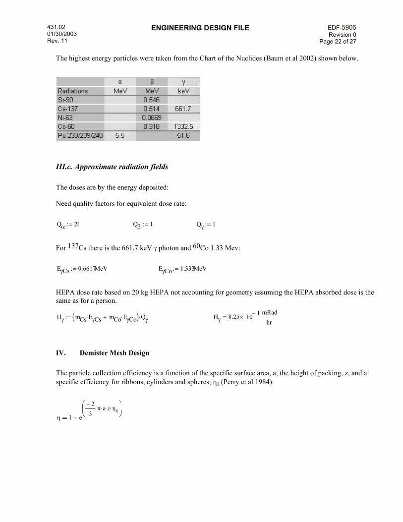
The highest energy particles were taken from the Chart of the Nuclides (Baum et al 2002) shown below.
III.c. Approximate radiation fields
The doses are by the energy deposited:
Need quality factors for equivalent dose rate:
Qα 20:= Qβ 1:= Qγ 1:=
For 137Cs there is the 661.7 keV γ photon and 60Co 1.33 Mev:
EγCs 0.6617MeV:= EγCo 1.333MeV:=
HEPA dose rate based on 20 kg HEPA not accounting for geometry assuming the HEPA absorbed dose is the same as for a person.
Hγ mCs EγCs⋅ mCo EγCo⋅+( ) Qγ⋅:= Hγ 8.25 10 1−×
mRadhr
=
IV. Demister Mesh Design
The particle collection efficiency is a function of the specific surface area, a, the height of packing, z, and a specific efficiency for ribbons, cylinders and spheres, ηt (Perry et al 1984).
η 1 e
2−
3π⋅ a⋅ z⋅ ηt⋅
−

431.02 01/30/2003 Rev. 11
ENGINEERING DESIGN FILE EDF-5905Revision 0
Page 23 of 27
The specific efficiency is a function of the separation number:
nsKm ρp⋅ Dp
2⋅ vo⋅
18 µ⋅ Do⋅
The Stokes-Cunningham Correction Factor, Km, is (http://courses.washington.edu/eh553a/Handout%201.pdf):
Km 12.52 λ⋅
Dp+ Based on the large number of wires in the mesh, this is assumed to be 1.0
since the mean free path, λ, is not known and usually applies to only very small particles.
Perry's provides a plot of this. For wire (cylinders) it is shown below:
Particle Target Efficiency
00.10.2
0.30.40.50.60.7
0.80.9
1
0.01 0.1 1 10 100
Separation Number
Effic
ienc
y
IV.1 Fabricated Unit by pushing wire into 6 inch basket
Because of the degrees of freedom (3), an example is provided using 0.5 mm steel wire. 1. Calculate the separation number with Km = 1 2. Find efficiency from above plot (ηt). 3. Calculate the efficiency from the equation.

431.02 01/30/2003 Rev. 11
ENGINEERING DESIGN FILE EDF-5905Revision 0
Page 24 of 27
Demister Data
Size of particle Vent header diameter
Dp 5µm:= Dv 4in:=
Stokes-Cunningham correction Empty bed velocity Wire diameter
Km 1:= vo4Qs
π Dv2
⋅:= vo 7.64
fts
= Do 1mm:=
Viscosity Packing height
µ 1.2 10 5−⋅
lbft s⋅
:= z 12in:=
Separation number:
nsKm ρp⋅ Dp
2⋅ vo⋅
18 µ⋅ Do⋅:= ns 0.36=
From the plot above:
η t 0.25:= a 50ft2
ft3:= Guess
η 1 e
2−
3π⋅ a⋅ z⋅ ηt⋅
−:= η 1= Since η > .999, this works
The volume of the basket is:
VBπ
4Dv
2⋅ z⋅:= VB 150.8in3
=
Estimate pressure loss

431.02 01/30/2003 Rev. 11
ENGINEERING DESIGN FILE EDF-5905Revision 0
Page 25 of 27
ftH2O 0.433psi:= inH2O
ftH2O12
:= gc 9.8kg m⋅
kgf s2⋅
:=
Gi vo ρ g⋅:=
ResDo Gi⋅
µ:= Res 1.32 102
×=
Based on this Re n 1.3:= and fm 5:=
φs .9:= guess for wire/cylinders
For a 50ft2
ft3= Aw a VB⋅:= Aw 4.36ft2=
LwAwπ Do⋅
:= Lw 4.23 102× ft=
Estimate the void ratio, εi.
εi 1
π
4Do
2⋅ Lw⋅
VB−:= εi 0.96=
Pressure drop analogue from a particle bed (Perry et al 1984). Note this is just an estimate based on a particle bed since a correlation is not available for this type of packing.
∆P ρg4 fm⋅ 1 εi−( )3 n−
⋅
φs3 n−
εi3
⋅
⋅z
Do⋅
vo2
2 gc⋅⋅:= ∆P 3.99 10 1−
× inH2O=

431.02 01/30/2003 Rev. 11
ENGINEERING DESIGN FILE EDF-5905Revision 0
Page 26 of 27
IV.2 Fabricated Unit by using known stainless demister mesh into 12 inch basket (recommended)
Specify: z 12in:= Packing height Do .006in:= Wire diameter
304 Stainless Steel, 19 1/2" x 100'
7.2 # Stainless Steel Woven Fabric Cloth Co. 5601 W. Slauson Avenue, Suite 260 Culver city, CA 90230-6598 Ben Yapyuco 310-258-9125 Fax: 310-258-9110
Separation number:
nsKm ρp⋅ Dp
2⋅ vo⋅
18 µ⋅ Do⋅:= ns 2.38=
From the plot above:
η t 0.7:=
Estimate specific surface area:
a4
Do:= a 8 103
×ft2
ft3=
η 1 e
2−
3π⋅ a⋅ z⋅ ηt⋅
−:= η 1=
ρmesh 7.2lb
ft3:= ρ steel 8.03
kgL
:=
Estimate void fraction
εi 1ρmeshρ steel
−:= εi 0.9856=

431.02 01/30/2003 Rev. 11
ENGINEERING DESIGN FILE EDF-5905Revision 0
Page 27 of 27
Res
Do Gi⋅
µ:= Res 2.01 101
×=
Based on this Re n 1.14:= and fm 6:=
∆P ρg4 fm⋅ 1 εi−( )3 n−
⋅
φs3 n−
εi3
⋅
⋅z
Do⋅
vo2
2 gc⋅⋅:= ∆P 0.251inH2O=
Corresponding close to vendor supplied value of 0.3 in H2O and showing the particle bed correlation possibly predicts too low for wire.