evaluation of pwa1483 for large single crystal igt blade
TRANSCRIPT

EVALUATION OF PWA1483 FOR LARGE SINGLE CRYSTAL IGT BLADE AI’PLICATIONS
Dilip M. Shah and Alan Cetel MlS114-43, Pratt 85 Whitney
400 Main Street, E. Hartford, CT 06033
Abstract
As a part of the Department of Energy “Land Based Turbine Casting Initiative” program, a high chromium containing, corrosion resistant single crystal alloy, PWA1483, was evaluated for large single crystal component application in industrial gas turbines (IGT). The objective of the program was to assess the impact of casting size on casting yield and structural performance of a large anisotropic body. For this purpose, large single crystal blades cast at two different growth rates, were evaluated for crystallographic quality, microstructure, and high angle boundary (HAB) type defects. Presence of HAB defects, is one of the principal factors, contributing to casting rejection. Testing consisted of 649’C tensile, and 76O“C, 871”C, and 982°C creep, as a fonction of the deviation of the tensile direction from <OOl>. PWA1483 bicrystals were cast, and tolerance to HAH was evaluated in creep at 760°C and 982OC. To assess the potential benefit of minor element additions on HAB tolerance, single crystals and bicrystals of hat%ium and boron modified PWA1483 were also evaluated.
The results show a linear decrease in tensile strength, and creep rupture life, and a corresponding increase in tensile elongation, with increasing deviation Tom <loo>. As expected, for the single crystal alloy PWA1483, with no minor elements, a precipitous drop in creep capability occurred, when grain boundary misorientation exceeded 10’. However, in the modified PWA1483, with deliberate additions of hafhium and boron, surprisingly, there was no significant drop in creep-strength even with grain boundary misorientation as high as 25”. The potential role of other factors, in this unexpectedly high tolerance to HAB of the modified alloy, is discussed further. Overall, the results provide a good basis for determining tradeoffs between, tensile strength, temperature capability, and grain boundary tolerance, vis-a-vis potential increase in casting yields with improvement in casting technology.
Introduction
The objective of this effort was to support a broad program to assess and address the potential technical and economic barriers in transitioning single crystal technology to large industrial gas turbine (IGT) components. Among a variety of associated issues, single crystal casting acceptance standards and post-casting processing, were considered two major factors affecting casting
yield and design performance of large components. Discussion in this paper will be primarily focused on the factors influencing casting acceptance standards.
Casting Acceptance Standards
Mechanical and physical properties of components cast in equiaxed polycrystallme nickel base superalloys can be assumed to be isotropic for all practical purposes, when the best conventional casting practice is used. Directionally solidified (DS) components with a columnar grain structure can be treated as transversely isotropic, with no variation of properties in the plane normal to the growth direction. Here, the superior creep resistance and low modulus, parallel to the columnar grain are well exploited when the component is DS along the stacking line of interest. However, a single crystal component is truly an anisotropic body, with significant variation in properties along diierent directions conforming to the crystal symmetry. To take optimum advantage of smgle crystal properties, control of crystallographic orientation with respect to the part geometry is required.
The additional orientation control is the price one has to pay to exploit the benefits stemming from the eliiation of all grain boundaries. Consequently, it must also be assured that the objective of the removal of all grain boundaries is adequately achieved. Any inadvertent presence of HAB must be detected and quantified. Minor low angle boundaries (LAB), are acceptable when they result in no significant loss in performance.
To achieve optimum performance with single crystal nickel base superalloys, the grain orientation with respect to the part geometry, and the tolerance of the material to HAH type defects, must be specified and controlled within limits.
CrvstallogtaDhic Characterization
While crystallographic control specifications are well in place for components currently used in aircraft or aeroderivative engines, a re-examination of the practice was deemed necessary, for heavy Came turbines, due to the 2-3X size increase of single crystal castings. The inevitable increase in total number of defects and variation in properties with increasing component volume, imparts additional cost and performance penalties. Furthermore, these issues must be addressed in the context of an altered operating scenario in which long term steady state durability is
295 SuperaIIoys 2ooo
Edited byT.M. Pollock, R.D. Kissinger, R.R. Bowman, K.A. Gmx M. McLean, S. Olson, and J.J. Schina
TMS (‘Ihe Minerals, Metals &Materials Society), 2ooO

more critical than the number of start-up and shutdown cycles. Specitic design of the components enters the picture as well. There is limited enghre experience with large single crystal components. An iterative approach with emphasis on crystallographic characterization and property evaluation is necessary to achieve the most cost-effective transition of single crystal technology.
Anisotronv of Phvsical and Mechanical Prouerties
For nickel base superalloys, with cubic structure, physical properties such as thermal expansion and thermal conductivity are isotropic and do not vary with crystallographic direction. Elastic modulus on the other hand, being a fourth rank tensor can be anisotropic, and it does vary signiticsntly with crystallographic orientation in nickel base alloys [1,2]. However, it is largely insensitive to specific alloy composition. In contrast, though, crystallographic slip dependent plastic properties, such as creep and tensile strength are not only anisotropic, but the extent of anisotropy is a strong function of alloy composition
Tensile Prouerties: There is ample evidence in the literature [1,3, 41 to suggest that tensile properties show significant anisotropic behavior. This variation is rooted in the competition between octahedral and cube slip behavior and therefore is also a complex function of y ’ size and alloy composition. The role of primary orientation, and dendrite splaying if any, on tensile properties must be recognized. From the turbine blade design standpoint, low temperature (-649V) tensile properties and associated low cycle fatigue (LCF) life are most critical, for the durability of the root attachment.
Creeo Resistance: Long term creep resistance is a lie liiting factor for ahfoils employed in heavy frame turbines for power generation, which undergo fewer start-up and shutdown cycles than aircraft engines. High temperature creep resistance in single crystal superalloys depends on a complex diiion controlled slip-climb mechanism, which is highly sensitive to alloy composition. Not only is creep strength, for a given crystallographic orientation, composition sensitive, but the orientation dependence of creep strength can also vary signiticantly with alloy chemistry. Both major [1,5] and minor elements [6] can alter the nature of creep anisotropy.
The nature of creep anisotropy has important implications for large single crystal castings. In the current design system, variation in properties along the principal loading directions, must be accounted for. In addition, potential increases in spatial variability in primary orientation (splaying) must be considered as well. This is tied into the state of the art of casting technology, and economic viability of process modifications such as seeding. To maximize the future efficient application of large single crystal components, it will be necessary to understand the three dimensional aspects of loading. Understanding the nature of anisotropy will be a first step in that direction
Effect of the High Angle Boundaries on Mechanical Properties
One of the principal motivations for pursuing directional solidification was the elimination of grain boundaries, normal to the principal stress direction. Successful application of columnar
grain Mar M200 (PWA 1422), required addition of hathium (Hf) to maintain transverse strength. The maximum benefit of single crystal application occurred when all grain boundary strengthening elements were reduced to sufficiently low levels that segregation was decreased. A concomitant increase in incipient melting point allowed greater latitude in alloy design and solution heat treatment. It is important to recognize that alloys developed specitically for single crystal application are not tolerant to the presence of grain boundaries, especially under creep conditions. Yet from an engineering standpoint, given the complexity of investment casting, the inadvertent presence of low angle boundaries must be tolerated to maintain an economically viable casting yield.
The critical question is what level of grain boundary misorientation or low augle boundary (LAB), can be tolerated without any significant loss in mechanical performance. The misorientation in its simplest form is quantifted as the minhnum angle of rotation necessary to bring the crystallographic frame of reference in one grain to map on that of the second grain. Owing to cubic symmetry, 24 axes of rotation can be identitied, but only one yields a minimum angle. If necessary, the mismatch angle can be separated into its twist and tilt components, but that requires knowledge of the orientation of the grain boundary with respect to the crystallographic frame of reference in one of the grains. However, the added characterization is of marginal value. Typically it is lmown that grain boundaries with misorientations beyond 10” result in a precipitous drop in creep-strength. It is interesting to note, that this is approximately the r&orientation limit, beyond which grain boundaries can no longer be treated in terms of a dislocation network, and consequently resulting in an order of magnitude increase in diffusion compared to that expected transgranularly [7]. This correlation is another strong indication supporting the view that environmental interaction is a principal factor contributing to the lack of grain boundary ductility.
One of the obvious options to improve the grain boundary tolerance of single crystals, is to add a limited amount of grahr boundary strengthening elements, and assess the trade-off between increases in casting yield and corresponding loss in high temperature performance.
For this study, PWA1483, a high chromium containing, single crystal alloy, specifically developed for IGT application was selected for evaluation. Large single crystal IGT blades were cast at two different growth rates, and were evaluated for orientation variability and low angle boundary type defects. The results showed little influence of growth rate on primary orientation. However, a reduction in the population of grain boundary defects was observed in crystals grown at the high growth rate.
The property characterization consisted of tensile (649OC), and creep (760, 871, and 982OC) properties as a function of orientation. To assess the tolerance of PWA1483 to low angle boundaries, bicrystals of known orientation were cast and evaluated in creep. To assess the potential benefit of minor element additions on high angle boundary tolerance, single crystal and bicrystal castings of hat&m and boron modified PWA1483 were also~evaluated.
296
The results show a linear decrease in tensile strength, and creep rupture life, accompanied by an increase in tensile elongation, with increasing deviation from <loo>. As expected, for the single crystal alloy PWA1483, containing no minor elements, a precipitous drop in creep strength occurred, when grain boundary misorientation exceeded 10”. However, in the modified PWA1483, with deliberate additions of hafhium and boron, no significant drop in creep-strength was observed, even with grain boundary misorientations as high as 25”. This was one of the most interesting findings of this evaluation. Broadly the results provide a good basis for determining tradeoffs between, tensile strength, temperature capability, grain boundary tolerance, and potential reduction in casting rejects, with improvement in casting technology.
Exnerimental Procedure
For this study, PWA1483 with 12% chromium, and a modification with hafnium and boron additions, were selected for evaluation. PWA1483 was specifically developed for marine and industrial gas turbine applications, requiring superior hot corrosion resistance. The advanced single crystal alloy PWA1484 was used for benchmarking casting yield in large components only. Nominal compositions for the three alloys are listed in Table I. The material procured for this study was cast by Howmet Corporation. Chemical analysis of all castings conflrmed that the concentration of all elements but boron, was within 2% of the nominal. Boron was analyzed to be consistently higher than the nominal target of 0.008 weight %, and varied between 0.0098 and 0.018 weight %.
To benchmark casting behavior in large components, Siemens’ large V84.4 blade tooling was used. Six large single crystal blades of PWA1483 and PWA1484 each, were cast in.2 molds at two different growth rates, differing by a factor of three. Maximum dimensions of these blades are approximately 21 x 14 x4cm.
Single crystal test material was variously cast as 15.9 mm and 25.4 mm diameter bars and 25.4 mm thick slabs. Molds of PWA1483 were obtained in all three configurations, whereas Modified PWA1483 was cast as slabs and large diameter bars.
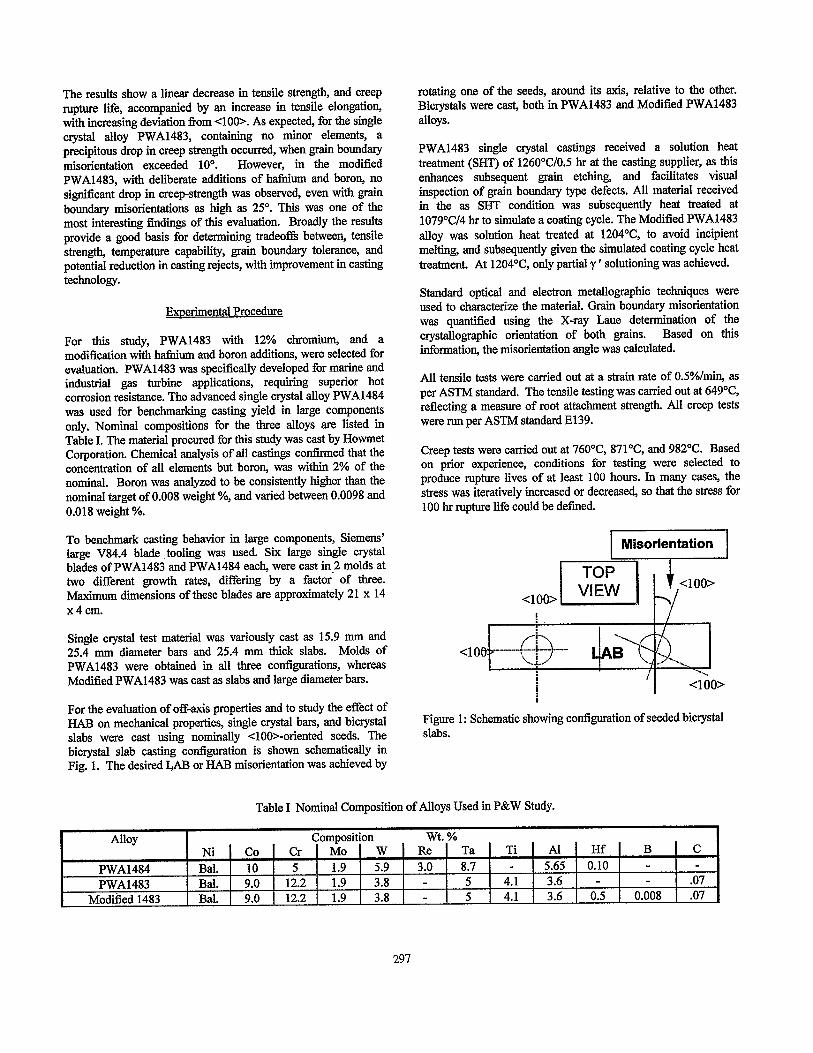
For the evaluation of off-axis properties and to study the effect of HAB on mechanical properties, single crystal bars, and bicrystal slabs were cast using nominally <lOO>-oriented seeds. The bicrystal slab casting configuration is shown schematically in Fig. 1. The desired LAB or HAB r&orientation was achieved by
rotating one of the seeds, around its axis, relative to the other. Bicrystals were cast, both in PWA1483 and Modified PWA1483 alloys.
PWA1483 single crystal castings received a solution heat treatment (SHT) of 126O”C/O.5 hr at the casting supplier, as this enhances subsequent gram etching, and facilitates visual inspection of grain boundary type defects. All material received in the as SHT condition was subsequently heat treated at 1079“C/4 hr to simulate a coating cycle. The Modified PWA1483 alloy was solution heat treated at 1204”C, to avoid incipient melting, and subsequently given the simulated coating cycle heat treatment. At 1204’C, only partial y ’ solutioning was achieved.
Standard optical and electron metallographic techniques were used to characterize the material. Grain boundary misorientation was quantified using the X-ray Laue determination of the crystallographic orientation of both grains. Based on this information, the n&orientation angle was calculated.
All tensile tests were carried out at a strain rate of O.S%/min, as per ASTM standard. The tensile testing was carried out at 649°C reflecting a measure of root attachment strength. All creep tests were run per ASTM standard E139.
Creep tests were carried out at 760°C, 871°C, and 982°C. Based on prior experience, conditions for testing were selected to produce rupture lives of at least 100 hours. In many cases, the stress was iteratively increased or decreased, so that the stress for 100 hr rupture life could be defined.
Figure 1: Schematic showing configuration of seeded bicrystal slabs.
Table I Nominal Composition of Alloys Used in P&W Study.
Alloy
PWA1484 PWA1483
Modified 1483
Composition wt. % Ni Co Cr MO W Re Ta Ti Al Hf Bal. 10 5 1.9 5.9 3.0 8.7 - 5.65 0.10 Bal. 9.0 12.2 1.9 3.8 - 5 4.1 3.6 - Bal. 9.0 12.2 1.9 3.8 - 5 4.1 3.6 0.5
B C - - - .07
0.008 .07
297

Results
Cast Microstructure Characterization of Lame IGT Blades
Twelve large single crystal IGT (V84.4) blades were cast in 4 molds, at 2 different growth rates in PWA1483 and PWA1484. The objective of this effort was to assess the quality of single crystal castings, as affected by the casting size, growth rate, and alloy chemistry. Obviously with the small population of castings evaluated, no statistically meaningful conclusions can be drawn, but only major trends in casting quality can be discerned.
Grain defects: In both alloys, the faster growth rate appeared to be beneficial, in that fewer grahr boundary type defects were revealed upon macroetching. At the slower growth rate, multiple defects were observed. Moreover, while all 3 blades of PWA1483, were virtuahy defect free at the faster growth rate, blades cast in PWA1484 were not. No defects were found in PWA1483 blade airfoils, whereas for PWA1484, one airfoil was cracked, and in two cases pits were observed at the tip end. One PWA1484 blade from each mold, showed orientation deviation of as much as 1Y from the primary <loo>.
Variation in ~rimaw orientation or S~lavina: Four blades, representing two alloys, and two growth rates in each case, were mapped with Laue X-ray difl?action to determine primary orientation variation, sometimes referred to as splaying. In each alloy/growth rate group, a blade with the largest deviation in primary orientation was selected, since such orientations have the least crystallographic symmetry. The results indicated virtually no splaying for both alloys at either growth rate. A variation of 2- 3O in primary and secondary orientation is considered natural, as it is comparable to the misorientation between neighboring dendrites. This can be verified using electron channeling pattern (ECP) mapping of dendrite orientation.
y’ size variation: Blades DS at the fast growth rate, were solution heat treated and sectioned in the root area, tip and mid-span of the airfoil. Optical metallography showed no evidence of under solutioning. To determine the finest y ’ size present in the dendritic core, surface replicas were prepared and examined at high magnification, in a transmission electron microscope. As expected, the average y’ size was observed to be larger in the massive root area compared to that in the tip area. While the size varied from -0.29 pm. to -0.13 pm for PWA1484, less variation (-0.3 pm. to -0.24 mu) was observed for PWA1483.
Dendritic Sub-structure: In order to discern any correlation between dendritic sub-structure, and rate of solidification, casting size, alloy chemistry, and casting defects; dendritic sub-structure of the available casting contigorations was studied.
Surprisingly, the results showed no significant difference in the dendrite density in the large IGT blades cast at growth rates differing by a factor of 3X. The dendritic density was estimated to be around 400 /cm2 in the root attachment and decreased to around 300 /cm2 in the airfoil. In comparison, the density of dendrites was observed to be higher (55O/cm*) in 25.4 mm thick bars and slabs, and almost a factor of two higher (86l/cm*) in the case of 15.9 mm diameter bars. While the difference in the density of dendrites between 15.9 mm and 25.4 mm diameter bars
was small, there appeared to be an increased volume of r/f eutectic phase in the latter. Another notable difference was the presence of secondary dendrite arms in Modified PWA1483 castings.
Evaluation of Off-axis Pronerties
Off-axis test specimens for tensile, and creep testing were machined from fully heat treated PWA1483, with the orientation of the specimen axis (a) varying Corn loo to 29” corn <OOl>. X-ray Laue data were further analyzed to define the actual crystallographic orientation of the specimen axis, within a standard stereographic triangle. However, the additional information proved academic, as there was insufficient data to discern any trend.
Tensile: All tensile testing was carried out at 649°C. Average results of four tests originating fkom a bar with a specific primary orientation (a) are plotted against the primary orientation angle a in Fig. 2. It is apparent that while 0.2% yield strength and ultimate tensile strength (UTS) decreases with increasing a, the % elongation increases. It is known that elastic modulus increases with increasing a. The results are not surprising, given that in the vicinity of x001>, single crystal nickel base superalloys deform by octahedral (lll)<llO> slip, and that strength is controlled by the critical resolved shear strength (CRSS) for the operative slip system. (See Reference 4 for further discussion.) For comparison, the average of duplicate test results for the modified alloy at 6.Y, are also plotted in Fig. 2.
% Elongation
Stress (MPa) ‘O”
800
700 10 I0
PWA1483
0.2 % YS
UTS
% Elong
Mod. PWA1483
0.2 % YS
600 (111111.11111111 ’ 8 IJTs 0 10 20 30
L-
A % Elong
Primary Orientation -- (deg. from cOOI>)
(111)<110> Schmid Law
Figure 2: 649’C tensile properties of PWA1483, versus primary orientation, measured in a0 from x001>. Results for Mod. PWA1483 are compared at a = 6.5".
Creeo: Off-axis creep behavior of PWA1483 was evaluated at two different stress conditions at 76O”C, 871°C, and 982°C. A total of 8 bars with different orientations were used. To facilitate a direct comparison of data, at different temperatures and stress combinations, groups of 6 specimens machined from the same bar, with presumably identical orientation, were tested at six different temperature and stress conditions. Thus at a given creep condition (temperature and stress), creep behavior was evaluated for a maximum of 8 different orientations.
298
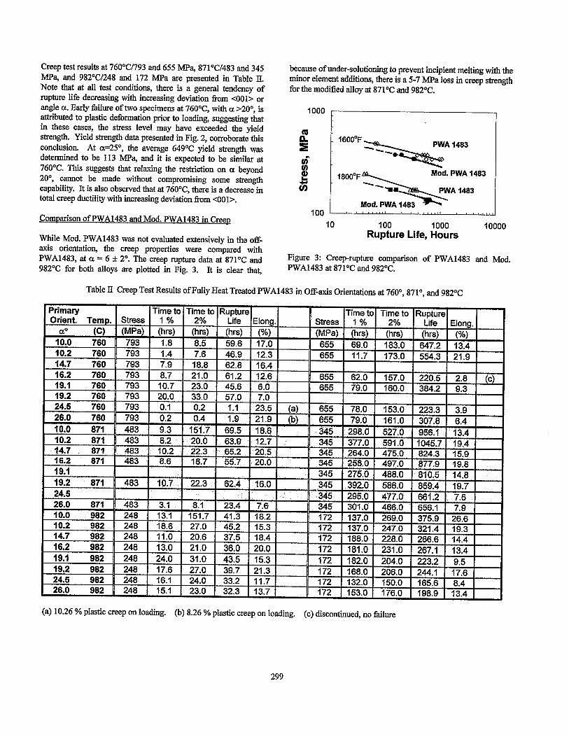
Creep test results at 76O”C/793 and 655 MPa, 871”C/483 and 345 MPa, and 982”C/248 and 172 MPa are presented in Table II. Note that at all test conditions, there is a general tendency of
because of under-solutioning to prevent incipient melting with the minor element additions, there is a 5-7 MPa loss in creep strength for the modified alloy at 871’C and 982°C.
rupture life decreasing with increasing deviation from <OOl> or angle a. Early failure of two specimens at 760°C, with a >20°, is attributed to plastic deformation prior to loading, suggesting that
1000
in these cases, the stress level may have exceeded the yield strength. Yield strength data presented in Fig. 2, corroborate this ([I
conclusion. At a=25”, the average 649°C yield strength was !h determined to be 113 MPa, and it is expected to be similar at m 76O’C. This suggests that relaxing the restriction on a beyond 8 20°, cannot be made without compromising some strength 2 capability. It is also observed that at 76O”C, there is a decrease in z total creep ductility with increasing deviation from x001>.
Comvarison of PWA1483 and Mod. PWA1483 in Creev
While Mod. PWA1483 was not evaluated extensively in the off- axis orientation, the creep properties were compared with PWA1483, at a = 6 f 2”. The creep rupture dam at 871°C and 982°C for both alloys are plotted in Fig. 3. It is clear that,
,I483 ‘“““°F~~*3
Mod. PWA 1483 I , , , , ,,,,, , , , , ,,,( 100 L
IO 100 1000 10000 Rupture Life, Hours
Figure 3: Creep-rupture comparison of PWA1483 and Mod. PWA1483 at 871°C and 982OC.
Table II Creep Test Results of Fully Heat Treated PWA1483 in Off-axis Orientations at 760°, 871”, and 982OC
(a) 10.26 % plastic creep on loading. (b) 8.26 % plastic creep on loading. (c) discontinued, no failure
299

Evaluation of Low and High Angle Boundaries (LAB & HAB)
A total of twelve (12) bictystal slabs were cast, six (6) each from PWA1483 and Modified PWA1483. Casting yield for the bicrystals was very poor because of slab geometry, and the targeted grain boundary misorientation angles were not achieved with any precision. For the purpose of this evaluation, the average boundary misorientation measured for each bicrystal casting was assigned to all specimens from the same casting. Grain boundary misorientation of individual specimens was not characterized. A typical macrograph, presented in Fig. 4, confirms that both grain boundary misorientation, and primary orientation, were achieved as intended. Note that from each bicrystal slab, baseline specimens, with no grain boundaries, were always procured. They were machined from one of the two crystals, avoiding the grain boundary.
f/----------1
Figure 4: A typical macrograph showing orientation relationship between two grains of a bicrystal specimen.
Creep Strength: The bicrystal specimens were tested in creep at 76O”C, and 982”C, at various stress levels so that stress for 100 hour rupture could be defined at each temperature for a given alloy. This required lowering the stress for specimens with high angle boundaries. The results for PWA1483 are presented in Table III, and Modified PWA1483 in Table IV. As noted earlier, the Modified PWA1483 alloy was cast with a late addition of 0.5 % Hf and 0.008 % B to PWA1483.
Comparison of data for PWA1483 and Modified PWA1483, clearly show that Modified PWA1483 is much more tolerant to grain boundary type defects. Specifically consider the short rupture life (38 and 97 hrs) of PWA1483 at 76O”C/414 MPa for a 2 1.2’ boundary. At the identical condition, a specimen of Modified PWA1483 had not ruptured after 4078 hrs. This is one of the most interesting findings of this investigation and will be discussed further.
Comparisons of fracture surfaces of creep specimens with and without high angle boundaries, showed a more or less featureless appearance in specimens with no grain boundaries, in contrast to an accentuated dendritic de-cohesion in specimens with high angle grain boundaries. Nonetheless, careful examinations of baseline specimens also revealed inter-dendritic failure. Since the artificially created boundaries in the present cases were largely tilt boundaries, the dendritic pattern was only uni-directional.
Discussion of Results
Oualitv of Large Single Crvstal IGT Blades
Effect of Growth Rate: Our observations suggest that it is feasible to DS defect free large single crystal IGT blades at higher growth rates. At appropriate fast growth, not only are high angle grain boundary type defects suppressed, but crystallographic splaying is also virtually absent. However, assessment of how this translates to a large-scale production environment, is beyond the scope of this effort. There is minor influence of alloy chemistry, but no meaningful conclusions can be drawn from this limited study. Based on this study, it appears that PWA1483 is less prone to defects than PWA1484, but the difference is not considered significant. Such small differences can be optimized simply with minor changes in casting process parameters.
Based on our observations, it appears that either the casting technique has achieved considerable maturity, or the massive volume of the part is naturally helpful. Excessive splaying is generally expected in asymmetric parts with undesirable thermal gradients in the plane normal to the growth direction. However, proper clustering of the parts in a mold may mitigate this factor; and a larger mass of material requiring a larger thermal flux, can help flatten out the temperature gradients within the mold.
The Role of Cast Microstructure: To gain some understanding of the interrelationship between cast microstructure, casting process and configuration, and alloy chemistry, dendritic microstructure and sub-structure misorientation were analyzed. Results showed no major differences in dendrite density in blades cast at baseline and at 3X higher relative growth rate. In fact the 15.9 mm diameter bars normally used for laboratory evaluation of mechanical properties exhibited distinctly higher dendrite density. In a sense, 25.4 mm diameter bars more closely simulated the dendritic density of large IGT blades. Another notable difference was the presence of secondary dendrite arms in Modified PWA1483, where melting characteristics were inevitably altered with the addition of boron and hafnium. The presence of secondary arms lead to slightly increased dendrite arm spacing. This was also accompanied by a slight increase in sub-structure misorientation. Based on past experience, this may imply an increased susceptibility to grain boundary type defects, because of less tolerance to transverse thermal gradient. However, a limited comparison of single crystal and bicrystal slabs cast in both alloys did not reveal any strong differences in frequency of grain boundary type defects between the two alloys.
Variation in Off-axis Pronerties
Tensile Properties: The 649’C, tensile data are plotted against the primary orientation angle a in Fig. 2. As expected, while yield strength and UTS decrease with increasing a, the % elongation increases. At low CL angle (<IS’) the Schmid factor in the vicinity of <OOl> orientation, for the primary {111}<110> slip system can be approximated as (1 +O.O 149a”)/d6.
300

Table III 760°C and 982°C Creep Test Results for PWA1483 Bicrystals
Table IV 760°C and 982°C Creep Test Results for Modified PWA1483 Bicrystals
1 LAB 1 Temp. Stress l Time to l Time to l Rupture1 Elong. 1 Temp. l Stress l Time to l Time to 1 Rupture1 Elena. 1 I1%12%1Llfel -1 I1%12%1ilfel -1 I
(deg.) Cl I [MPal I thrsl I thrsl I fhrsl I /%I I I I No bound. 760 690 18.7 98; 1 ‘207- 1 i4.6 i4.d I 43.i I i5.i I 49.d 18O.i 13.9
No bound. 1 760 1 690 1 30.0 66.0 187.8 13.8
No bound. 1 760 I 690 I 35 77 176.2 12.6
I 13.7 ii 760 1 890 _-- 13.7 760 724 21.2 760 414 21.2 760 552
I I I
982 1 172 1 26.9 1 52.0 1 82.2 1 6.9 1 16.7 1 48.0 1 134.1 1 1 1 1 1
I 5.1 18.1 55.9 8.5 982 172 1 34.0 1 63.0 1 112 1 8.5 I
4078.1 - - 4.8 I 388 1 814 i1442.6 t
0.0 4.9 982 207 13.8 24.0 30.4 4.2
I I I 8 I I I ---
21.2 1 760 1 690 1 34.0 1 69.0 1 90.7 / 3.2 1 982 t 172 1 44.0 1 67.0 1 69.6 1 3.2
+ Discontinued, no failure
Thus yield strength can be linearly related to critical resolved shear strength (rG ) by the relation
o, = ,cc 46 (l-0.0149a’)
In Fig. 2, the 0.2% yield strength data reasonably fits this description, if it is assumed that z, = 445 MPa. Also plotted in Fig. 2, for comparison, are tensile data for Modified PWA1483 at 6.5”. It is evident that while there is little change in UTS, 0.2% yield strength is significantly reduced for the modified alloy.
301

Green: As noted earlier, in all cases, except at 76O”C/793 MPa , creep rupture life and time to 2% decrease with increasing deviation of 0: from <OOl>. The rate of decrease in rupture life was observed to be much higher than that for time to 2% creep. A Larson-Miller plot of the data, presented in Fig.& depicts this trend in rupture life. In the figure, rupture life data at c~=lO” and c&S’ are compared. Based on this plot a decrease of 207 in L-M parameter is determined, for increasing CL from loo to 25“. This translates into a 35% drop in rupture lie at constant stress, or a 8°C temperature debit for the same creep strength, or a 30-40 MPa drop in creep strength, at the same temperature. Obviously, the decrease in creep capability will be less significant if time to 2% data were compared in Fig. 5. It is interesting to note that the loss in creep strength with a 15’ deviation in primary orientation is comparable to the loss in creep-strength for the modified alloy with respect to PWA1483.
1000
PWA1483 cu
% 6 ii
6
100 1 -I 24 26 28 30 32
L-M Parameter (T K)[22 +log(t hr) ] x10’
Figure 5: Larson-Miller comparison of creep rupture life of PWA1483 with primary orientation deviations(a) of 10” and 25”.
Grain Boundarv Tolerance
From log-log plots of stress vs. rupture life, stress for rupture in 100 hrs was determined for PWA1483 and Modified PWA1483, respectively, at 760°C and 982V, for various grain boundary misorientations. The results are depicted in Fig. 6, as a plot of stress for lOO-hr rupture, versus grain boundary n&orientation for both alloys at both temperatures. Note that while the stress drops precipitously for grain boundary n&orientations greater than 10” for PWA1483, there is virtually no change in the case of Modified PWA1483. In fact, as reported in Table IV, testing of a specimen cast in Modified PWA1483 was discontinued at 760°C/414 MPa, after 4078 hours. The results clearly suggest that additions of minor elements, boron and hathium, in the Mod. PWA1483, has signiticantly increased its tolerance to grain boundary type defects, It is apparent from Fig. 6, that there is almost a 50% debit in stress capability for PWA1483 (76O’C) with HAB greater than 20’. However, for the Modified PWA1483 alloy, HABs do not signiticantly debit creep strength.
Stress debit is not the only measure of the impact of grain boundary type defects. Total elongation at failure is another measure of margin of safety in engineering applications. Creep rupture elongation measured after failure for both PWA1483 and
Modified PWA1483, are plotted against grain boundary n&orientation in Fig. 7. The elongation data at 760°C and 982’C for each alloy follow the same trend with grain boundary misorient&ion, and hence only one trend line is shown for each alloy. Note that even in the presence of a high angle boundary defect, the modified alloy exhibits ductility greater than 2%, compared to virtually none (~0.2%) in the base alloy. It is evident that addition of minor elements not only improves the stress capability, but also enhances ductility in the presence of HABS.
900
600
700
600
500
400
300
200
100
0 0 5 10 15 20 25
Grain Boundary Mlsorientation
Figure 6: Stress for 100 hr rupture versus grain boundary n&orientation at 760°C and 982’C for PWA1483 and Modified PWA1483.
16
14
12
10
6
6
4
2
0 0 5 10 15 20 25
Grain Boundary Misorinetation
Figure 7: Creep rupture elongation at 760°C and 982V, versus grain boundary misorientation for PWA1483 and Modified PWA1483. Trend in ductility behavior is almost identical at both temperatures.
While our results, on improving grain boundary tolerance with additions of B and Hf, is not totally surprising, the robust tolerance to HAB as large as 20°, is not in agreement with past experience. Ross and O’Hara [8], in their study of the alloy Rend N4, concluded that addition of minor elements at low level, enhance the grain boundary tolerance to 12”. Past testing of columnar grain alloys such as PWA1422, in transverse orientation, has always shown a significant creep strength debit in spite of even greater additions of minor elements. We shall return to this aspect later in the discussion.
As alluded to earlier, for alloys without minor elements, the tolerance to grain boundaries with 6-loo misorientation, coincides with a steep increase in grain boundary diffusion. This implies that without the minor elements, grain boundary failure may be further aggravated by environmental interactions. In the presence of minor elements, this aspect is largely mitigated. Thus, once the minor elements are added, the loss of creep strength may not originate entirely from the grain boundary per se, but may be
302

dependent on transgranular creep behavior. Transgranular creep deformation is obviously controlled by the orientation dependence of creep behavior, as well as deformation compatibility in the vicinity of the grain boundary.
Role of Primarv Orientation: When a bicrystal is tested in creep, with the grain boundary oriented normal to the stress axis, the grain boundary misorientation alone is not sufficient to define the creep behavior, especially for high angle boundaries. For example, a 20’ bicrystal can be produced with a pure twist boundary with both grains oriented along either a <loo> or <llO> direction. Alternatively, a 20’ tilt boundary can be produced with the orientation of each grain approximately 10” away from <loo>, or one grain close to <loo>, and the other off by 20’ IYom <loo>. Since the latter case was the way bicrystals were produced for this study, it is expected that creep properties will, as a minimum, degrade as the primary orientation of one of the crystal shifts away f?om <loo>.
To assess this effect, 76O”C/690 MPa rupture life is plotted in Fig. 8 for both bicrystals and off-axis specimens. Note that for PWA1483 bicrystals, the grab-r boundary misorientation obviously dominates. However, in the case of Mod. PWA1483, the inverse relation observed with grain boundary misorient&on, is similar to the trend observed between rupture life and primary orientation for PWA1483. At 982YY30 MPa, the n&orientation relationship for the Mod. PWA1483 follows the same trend as primary orientation for PWA1483, although the PWA1483 rupture lives are consistently higher, as shown Fig. 9. This difference in creep strength is consistent with the creep-rupture comparison of both alloys (c&O) presented in Fig. 3.
The dam for both alloys (L&I < 6” and HAB 6-20’) is also compared on plots of stress vs. rupture life at 760 and 982°C (Figs. 10 and 11). At both test temperatures, PWA1483 creep strength is significantly debited by HAB, while the modified alloy shows much less of an effect. Even though the modified ahoy has lower absolute creep-strength capability than PWA1483, the modified alloy shows a large advantage when comparisons are made with material containing HAB. As shown in Figs. 10 and 11, in material containing HAH, the modified alloy shows more than a 50% stress advantage at 76O”C, and an -10% stress advantage at 982’C, over PWA1483.
Role of x110> orientation: In a <loo> oriented single crystal component, at least two secondary directions in the transverse plane will always coincide with x110>. This is known to be the weakest direction in creep, although single crystal components are used in practice in spite of that. The question is, whether a 20” boundary with ~1 lO> orientation would have performed as well. Unfortunately, no creep data were generated in <llO> oriented PWA1483. However, if past results were any guide, rupture life would be expected to be very low. If20’ bicrystals were grown with average grain orientations near <llO>, chances are that creep results would have been poor. This may represent the worst condition, similar to columnar grain material tested in a transverse diction. However, the key question is whether transverse properties are always poor because of the presence of gram boundaries or because of crystal orientation.
LI PWA1483 Life vs.
0 5 IO 15 20 25 30
Misorientation, or Primary Orientation, Degrees
Figure 8: 76O”C/690 MPa creep-rupture life of PWA1483 and Mod.PWA1483 vs. grain boundary misorientation, and primary orientation.
Mod. PWA 1483 \ Misorientation
Misorientation
Misor;jentation~or PrimaSry OrleZation, 25 30
Figure 9: 982’C/30 MPa creep-rupture life of PWA1483 and Mod.PWA1483 vs. gram boundary misorientation and primary misorientation.
1000
100
10 100 1000
Rupture Life, hours 10000
Figure 10: Effect of HAB on 760°C creep-rupture life of PWA1483 vs. Mod. PWA1483.
A PWA1483 HAB PWA Ia A Mod. PWA1483 HAB m PWA 148;
0 PWA1483 LAB
1 10 100
Rupture Life, Hours 1000
Figure 11: Effect of HAB on 982°C creep-rupture life of PWA1483 vs. Mod. PWA1483.
303

To answer this question, we revisited results for Mar M2OO+Hf, for which data in both columnar grain, and single crystal [4], form were available.
Mar M200 Exnerience: 760°C creep-rupture life for Mar M2OO+Hf for columnar grain (CG) material in longitudinal and transverse directions, and single crystal material in <loo> and <llO> orientations, is presented Fig. 12. Linear parallel extrapolation is used to compare data for diierent orientations generated at different stresses. Clearly the wide scatter in data for the transverse orientation spans the range tiom the lowest rupture life for <loo>, down to lower than X110> orientated single crystals. If what we have observed for Mod.PWA1483 were true for Mar M2OO+Hf, the large scatter in rupture life in the transverse orientation must be a consequence of the uncontrolled nature of primary orientation of grains in a transverse specimen. This suggests that there may be nothing unique about high Cr containing Mod.PWA1483. The high tolerance to grain boundary misorient&ion, may be a result of testing x100>-oriented bicrystals. Evaluation of HAB bicrystals with <llO> primary orientation is needed to detine the worst case scenario.
CG
1 IO 100 1000 10000
Creep-rupture Life, hrs
Fig. 12: Transverse 760°C creep-rupture lie for columnar grain Mar M2OO+Hf spans range between longitudii and <llO> single crystal data at 690 MPa.
1.
2.
3.
4.
5.
SUmmarY
High growth rate seems to be helpful in suppressing grain boundary type defects as well as dendrite splaying in large single crystal castings. At the current development of casting technology, no signiticant difference in behavior of castable single crystal alloys could be discerned. As expected, both low temperature tensile and high temperature creep strength of PWA1483 decrease with increasing deviation from the primary x001> direction. Tolerance to high angle grain boundaries is significantly improved with minor element additions in creep at all temperatures. However, a creep strength debit is associated with this benefit at high temperatures. In spite of a creep strength improvement with minor element additions, in the presence of high angle grain boundaries, creep ductility is liited compared to defect-l?ee single crystal. Comparison with data for Mar M2OO+Hf, suggests that the observed exceptional tolerance to high angle grain
boundaries with minor element additions, may be a result of the <loo> orientation of the bicrystals evaluated.
6. Evaluation of <llO> oriented high angle boundaries is necessary to assess the true benefit of addition of minor elements to single crystal alloys for improving tolerance to occasional grain boundary type defects.
7. With improvement in casting technology and better understanding of material behavior, and design tradeoffs, application of single crystal technology for large IGT seems economically viable.
Acknowledgement
Thanks are due to Mr. Allan Price of Howmet Research Corporation for supply of single crystal castings. Many thanks are due to Mr. Glenn Cotnoir of P &W for technical help.
References
1. R. P. Dalal, C. R. Thomas, and L. E. Dardi, “The Effect of Crystallographic Orientation on the Physical and Mechanical Properties of an Investment Cast Smgle Crystal Nickel-Base Superalloy” (SUPERALLOYS 1984, Edited by M. Gell, et al., TMS-AIM& Warrandale, PA., 1984) 185.
2. D. N. Duhl in Sunerallovs. Sunercomnosites. and Sunerceramics, (Edited by J. K Tien and T. Caulfield, Academic Press, Boston) 149.
3. R. A. MacKay, R. L. Dreshfleld, and R D. Maier, “‘Anisotropy of Nickel-Base Superalloy Single Crystals” (SUPERALLOYS 1980, Edited by J. K. Tien et al., ASM, Metals Park, Ohio, 1980, p.385.
4. D. M. Shah and D. N. Dubl, ‘The Effect of Orientation, Temperature and Gamma Prime Size on the Yield Strength of a Smgle Crystal Nickel Base Superalloy” (SUPERALLOYS 1984, Edited by M. Gel1 et al., TMS-AlME, Warrandale, PA., 1984) 105.
5. D. M. Shah and A. Cetel, “Creep Anisotropy in Nickel Base ‘y, y, y/y Superalloy Single Crystals” (SUPERALLOYS 1996, Edited by R. D. Kissinger et al., TMS, Warrandale, PA) 273.
6. D. M. Shah and D. N. Duhl, “Effect of Minor Elements on the Deformation Behavior of Nickel-Base Superalloys” (SUPERALLOYS 1988, Edited by D. N. Duhl et al., TMS- AIME, Warm&ale, PA., 1988) 693.
7. Shewman, Paul G., Diffusion in Solids, McGraw-Hill, New York, 1963, p.173.
8. E. W. Ross and K. S. O’Hara, “Rene N4: A Fit Generation Smgle Crystal Turbine Airfoil Alloy With Improved Oxidation Resistance, Low Angle Boundary Strength and Superior Long Time Rupture Strength” (SUPERALLOYS 1996, Edited by R D. Kissinger et al., TMS, Warrandale, PA) 19.
304