evaluation of the lte positioning capabilities under typical multipath...
TRANSCRIPT

Evaluation of the LTE Positioning CapabilitiesUnder Typical Multipath Channels
Jose A. del Peral-Rosado, Jose A. Lopez-Salcedoand Gonzalo Seco-Granados
Universitat Autonoma de Barcelona (UAB)Bellaterra, Spain
Email: {JoseAntonio.DelPeral, Jose.Salcedo,Gonzalo.Seco}@uab.cat
Francesca Zanierand Massimo Crisci
European Space Agency (ESA)Noordwijk, The Netherlands
Email: {Francesca.Zanier, Massimo.Crisci}@esa.int
Abstract—The Long Term Evolution (LTE) is a mobile com-munication standard that is receiving significant attention, andespecially offers positioning capabilities by specifying a dedicateddownlink signal, i.e. the positioning reference signal (PRS). Thus,this technology can improve the location of mobile terminalsoperating in harsh environments, such as urban or indoorscenarios. This paper presents a study of the impact of thechannel on the positioning capabilities of LTE with respect to thesignal bandwidth. For that purpose, typical channel models, suchas those recommended by the International TelecommunicationUnion (ITU), are used to obtain timing error distributions bymeans of the histogram of maximum likelihood estimates. Theresults obtained represent the worst-case scenario since theapplied estimation process does not consider the presence ofthe multipath channel. The dependency of the timing errordistributions with respect to the type of channel model is alsoanalysed.
I. INTRODUCTION
Most localization applications are nowadays based onGlobal Navigation Satellite Systems (GNSS). However, therobustness of mass-market GNSS receivers is compromised inchallenging environments, such as indoor or urban scenarios.In these circumstances, the presence of blocking obstaclesand propagation disturbances prevent them from observingthe expected perfect clear-sky conditions that were assumedin the nominal design of the system. Complementary systemsare usually proposed to assist the operation of GNSS systems.
Traditionally, cellular networks have provided the nec-essary assistance data to improve the overall performance,i.e. assisted-GNSS (A-GNSS), or estimated roughly the userposition based on the cell radius, i.e. Cell-ID method. Butrecently, new positioning capabilities have been incorporatedin order to satisfy two main drivers: legal mandates for locationidentification of emergency calls (e.g. E911 in US or E112 inEurope), and commercial applications or location-based ser-vices (LBS), such as navigation, advertising or social media.In this sense, the Long Term Evolution (LTE) technology,specified by the 3rd Generation Partnership Project (3GPP)consortium [1], has defined a dedicated downlink signal forObserved Time Difference of Arrival (OTDoA) positioning,i.e. the positioning reference signal (PRS). In fact, the LTEdownlink is defined by a multicarrier Orthogonal FrequencyDivision Multiplexing (OFDM) signal, which is well-known
signal in wireless communications because of its flexibility,spectral efficiency and robustness against frequency-selectivefading introduced by multipath, among other advantages withrespect to traditional single-carrier signals.
Multipath is certainly a major source of positioning error,especially in indoor and urban areas, where non-line-of-sight(NLOS) conditions are predominant. This topic has receivedspecial attention for years within the GNSS community, dueto the degradation that NLOS introduces in terms of timedelay estimation accuracy. In contrast, terrestrial positioningsystems have not addressed significantly this topic since theterrestrial wireless technologies have traditionally focused oncommunication purposes, and only recently has started toanalyse this issue in the literature. Focusing on the time delayestimation (TDE), ultra-wideband (UWB) is an example ofsystem that has been used for localization purposes in densemultipath environments, as shown in [2]. Focusing on otherterrestrial systems, the Digital Video Broadcasting (DVB)systems, which is based on OFDM modulation, have beenrecently studied for signals-of-opportunity (SoO) applications,such as in [3] and [4]. These studies provide positioning resultsobtained with channel measurements that can lead to realisticassessments of the channel impact. In the case of LTE, studiesusing measurements campaigns can also be found, such asin [5] with the positioning reference signal or in [6] with aGNSS hybridisation. The resulting multipath impact on thepositioning error is usually assessed by using simple metrics,such as the mean delay or center of gravity of the powerdelay profile, as it is described in [7] and [8]. However, thesemetrics may not characterize precisely the accuracy impact forevery possible bandwidth, and they should be considered asan approximation, as it is shown in this paper.
Although channel model advances are motivated by In-ternational Telecommunication Union (ITU) or the EuropeanCooperation in Science and Technology (COST), few studies,such as in [9], are trying to find the detailed impact ofthe multipath channel on the positioning capabilities of aterrestrial multicarrier system. Thus, the aim of this paper isto characterize the impact of typical channels on the pseudo-range estimation using LTE signals, such as the positioningreference signal (PRS), and the dependency of ranging errors
2012 6th Advanced Satellite Multimedia Systems Conference (ASMS) and 12th Signal Processing for Space CommunicationsWorkshop (SPSC)
978-1-4673-2676-6/12/$31.00 ©2012 IEEE 139
produced with respect to the type of channel model. In SectionII, a description of the LTE standard is presented by followingthe preliminary analysis on the LTE signal structure shown in[10]. The typical channel models are described in Section III.The maximum likelihood estimation is introduced in SectionIV, which is used to produce the multipath error envelopewith a two-ray multipath model in Section V. In SectionVI, the timing error distribution of typical channel modelsis obtained by means of the histogram of the maximumlikelihood estimates. The evaluation of these distributions isdone for fixed and non-fixed tap delay channels. Finally, wedraw the conclusions in Section VII.
II. LONG TERM EVOLUTION (LTE)
Long Term Evolution (LTE) moves towards the fourth gen-eration (4G) of mobile communications. Most of its standard,which is driven by 3GPP, has been inherited from the Uni-versal Mobile Telecommunication System (UMTS) in orderto maintain backward compatibility. The main new featuresintroduced are the downlink Orthogonal Frequency-DivisionMultiple Access (OFDMA) and the Multiple Input MultipleOutput (MIMO) data transmission. The signal bandwidth isscalable from 1.4 MHz to 20 MHz with a symbol period Ts
of 66.67 µs, which corresponds to a subcarrier spacing Fsc of15 kHz.
According to the LTE specification [11], the downlinkpositioning procedure, defined by the OTDoA method, uses thedifference in the arrival times of downlink radio signals frommultiple base stations (i.e. eNodeBs) to compute the user po-sition. The method relies on a network-based strategy becausethe eNodeB locations are not provided to the user. First, theuser equipment (UE) request assistance information to proceedwith the timing measurements. Then, the LTE PositioningProtocol (LLP) transfers the UE measurements to the locationserver, E-SMLC (Enhanced Serving Mobile Location Center).Based on the UE measurements, the E-SMLC estimates theUE position using a trilateration technique, and this positioninformation is finally sent back to the user.
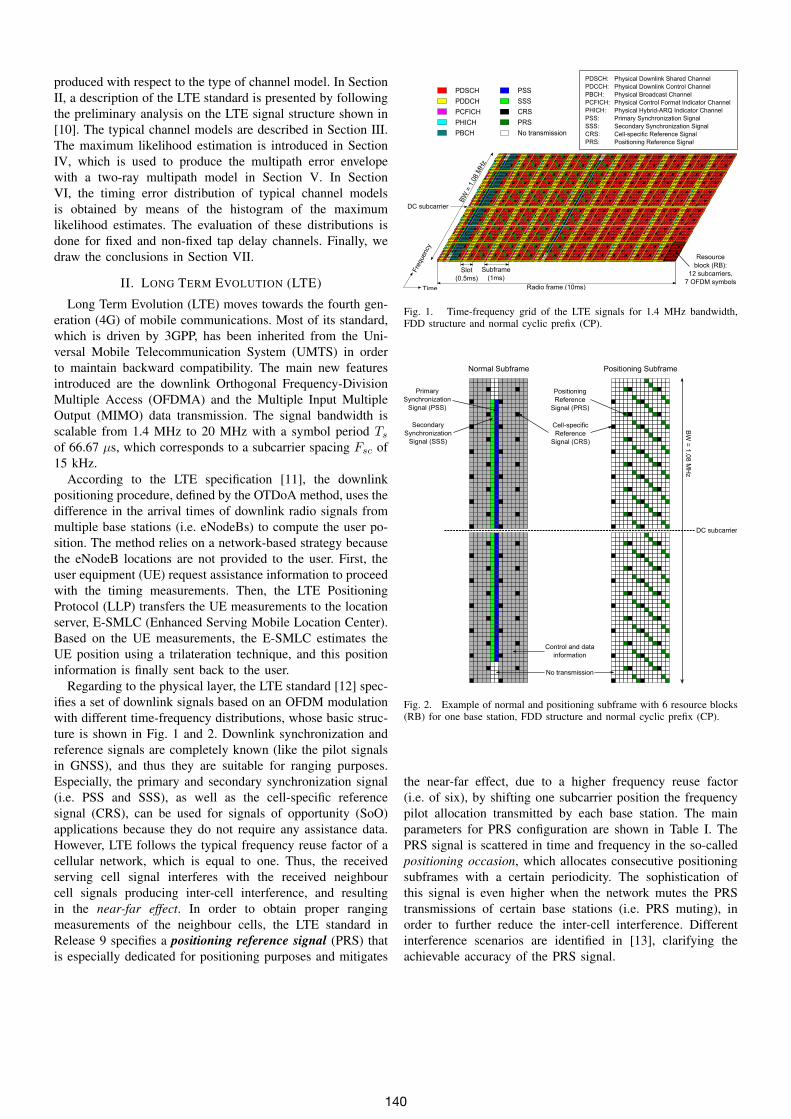
Regarding to the physical layer, the LTE standard [12] spec-ifies a set of downlink signals based on an OFDM modulationwith different time-frequency distributions, whose basic struc-ture is shown in Fig. 1 and 2. Downlink synchronization andreference signals are completely known (like the pilot signalsin GNSS), and thus they are suitable for ranging purposes.Especially, the primary and secondary synchronization signal(i.e. PSS and SSS), as well as the cell-specific referencesignal (CRS), can be used for signals of opportunity (SoO)applications because they do not require any assistance data.However, LTE follows the typical frequency reuse factor of acellular network, which is equal to one. Thus, the receivedserving cell signal interferes with the received neighbourcell signals producing inter-cell interference, and resultingin the near-far effect. In order to obtain proper rangingmeasurements of the neighbour cells, the LTE standard inRelease 9 specifies a positioning reference signal (PRS) thatis especially dedicated for positioning purposes and mitigates
PDSCH
PDDCH
PCFICH
PHICH
PBCH
PSS
SSS
CRS
PRS
No transmission
Resource
block (RB):
12 subcarriers,
7 OFDM symbolsTime
Fre
quency
Radio frame (10ms)
Slot
(0.5ms)
Subframe
(1ms)
Physical Downlink Shared Channel
Physical Downlink Control Channel
Physical Broadcast Channel
Physical Control Format Indicator Channel
Physical Hybrid-ARQ Indicator Channel
Primary Synchronization Signal
Secondary Synchronization Signal
Cell-specific Reference Signal
Positioning Reference Signal
PDSCH:
PDCCH:
PBCH:
PCFICH:
PHICH:
PSS:
SSS:
CRS:
PRS:
DC subcarrier
BW
= 1
.08 M
Hz
Fig. 1. Time-frequency grid of the LTE signals for 1.4 MHz bandwidth,FDD structure and normal cyclic prefix (CP).
Normal Subframe Positioning Subframe
DC subcarrier
Primary
Synchronization
Signal (PSS)
Secondary
Synchronization
Signal (SSS)
BW
= 1
.08
MH
z
No transmission
Control and data
information
Positioning
Reference
Signal (PRS)
Cell-specific
Reference
Signal (CRS)
Fig. 2. Example of normal and positioning subframe with 6 resource blocks(RB) for one base station, FDD structure and normal cyclic prefix (CP).
the near-far effect, due to a higher frequency reuse factor(i.e. of six), by shifting one subcarrier position the frequencypilot allocation transmitted by each base station. The mainparameters for PRS configuration are shown in Table I. ThePRS signal is scattered in time and frequency in the so-calledpositioning occasion, which allocates consecutive positioningsubframes with a certain periodicity. The sophistication ofthis signal is even higher when the network mutes the PRStransmissions of certain base stations (i.e. PRS muting), inorder to further reduce the inter-cell interference. Differentinterference scenarios are identified in [13], clarifying theachievable accuracy of the PRS signal.
140
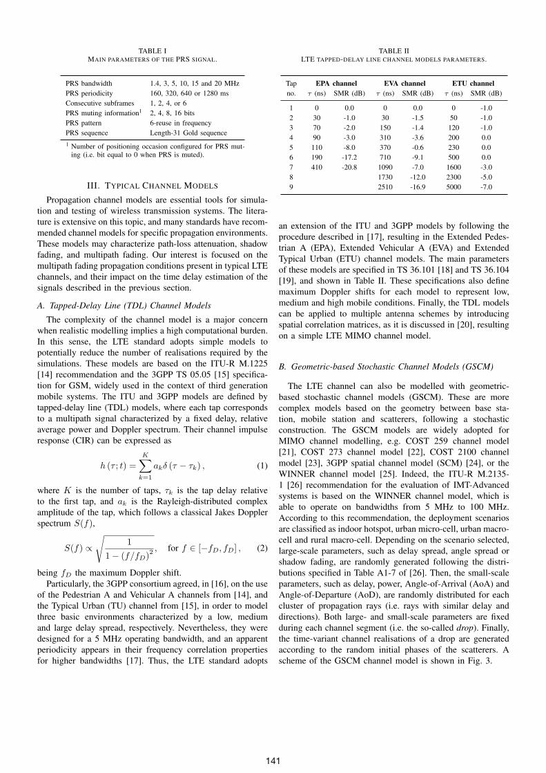
TABLE IMAIN PARAMETERS OF THE PRS SIGNAL.
PRS bandwidth 1.4, 3, 5, 10, 15 and 20 MHzPRS periodicity 160, 320, 640 or 1280 msConsecutive subframes 1, 2, 4, or 6PRS muting information1 2, 4, 8, 16 bitsPRS pattern 6-reuse in frequencyPRS sequence Length-31 Gold sequence1 Number of positioning occasion configured for PRS mut-
ing (i.e. bit equal to 0 when PRS is muted).
III. TYPICAL CHANNEL MODELS
Propagation channel models are essential tools for simula-tion and testing of wireless transmission systems. The litera-ture is extensive on this topic, and many standards have recom-mended channel models for specific propagation environments.These models may characterize path-loss attenuation, shadowfading, and multipath fading. Our interest is focused on themultipath fading propagation conditions present in typical LTEchannels, and their impact on the time delay estimation of thesignals described in the previous section.
A. Tapped-Delay Line (TDL) Channel Models
The complexity of the channel model is a major concernwhen realistic modelling implies a high computational burden.In this sense, the LTE standard adopts simple models topotentially reduce the number of realisations required by thesimulations. These models are based on the ITU-R M.1225[14] recommendation and the 3GPP TS 05.05 [15] specifica-tion for GSM, widely used in the context of third generationmobile systems. The ITU and 3GPP models are defined bytapped-delay line (TDL) models, where each tap correspondsto a multipath signal characterized by a fixed delay, relativeaverage power and Doppler spectrum. Their channel impulseresponse (CIR) can be expressed as
h (τ ; t) =K∑
k=1
akδ (τ − τk) , (1)
where K is the number of taps, τk is the tap delay relativeto the first tap, and ak is the Rayleigh-distributed complexamplitude of the tap, which follows a classical Jakes Dopplerspectrum S(f),
S(f) ∝√
1
1− (f/fD)2 , for f ∈ [−fD, fD] , (2)
being fD the maximum Doppler shift.Particularly, the 3GPP consortium agreed, in [16], on the use
of the Pedestrian A and Vehicular A channels from [14], andthe Typical Urban (TU) channel from [15], in order to modelthree basic environments characterized by a low, mediumand large delay spread, respectively. Nevertheless, they weredesigned for a 5 MHz operating bandwidth, and an apparentperiodicity appears in their frequency correlation propertiesfor higher bandwidths [17]. Thus, the LTE standard adopts
TABLE IILTE TAPPED-DELAY LINE CHANNEL MODELS PARAMETERS.
Tap EPA channel EVA channel ETU channelno. τ (ns) SMR (dB) τ (ns) SMR (dB) τ (ns) SMR (dB)
1 0 0.0 0 0.0 0 -1.02 30 -1.0 30 -1.5 50 -1.03 70 -2.0 150 -1.4 120 -1.04 90 -3.0 310 -3.6 200 0.05 110 -8.0 370 -0.6 230 0.06 190 -17.2 710 -9.1 500 0.07 410 -20.8 1090 -7.0 1600 -3.08 1730 -12.0 2300 -5.09 2510 -16.9 5000 -7.0
an extension of the ITU and 3GPP models by following theprocedure described in [17], resulting in the Extended Pedes-trian A (EPA), Extended Vehicular A (EVA) and ExtendedTypical Urban (ETU) channel models. The main parametersof these models are specified in TS 36.101 [18] and TS 36.104[19], and shown in Table II. These specifications also definemaximum Doppler shifts for each model to represent low,medium and high mobile conditions. Finally, the TDL modelscan be applied to multiple antenna schemes by introducingspatial correlation matrices, as it is discussed in [20], resultingon a simple LTE MIMO channel model.
B. Geometric-based Stochastic Channel Models (GSCM)
The LTE channel can also be modelled with geometric-based stochastic channel models (GSCM). These are morecomplex models based on the geometry between base sta-tion, mobile station and scatterers, following a stochasticconstruction. The GSCM models are widely adopted forMIMO channel modelling, e.g. COST 259 channel model[21], COST 273 channel model [22], COST 2100 channelmodel [23], 3GPP spatial channel model (SCM) [24], or theWINNER channel model [25]. Indeed, the ITU-R M.2135-1 [26] recommendation for the evaluation of IMT-Advancedsystems is based on the WINNER channel model, which isable to operate on bandwidths from 5 MHz to 100 MHz.According to this recommendation, the deployment scenariosare classified as indoor hotspot, urban micro-cell, urban macro-cell and rural macro-cell. Depending on the scenario selected,large-scale parameters, such as delay spread, angle spread orshadow fading, are randomly generated following the distri-butions specified in Table A1-7 of [26]. Then, the small-scaleparameters, such as delay, power, Angle-of-Arrival (AoA) andAngle-of-Departure (AoD), are randomly distributed for eachcluster of propagation rays (i.e. rays with similar delay anddirections). Both large- and small-scale parameters are fixedduring each channel segment (i.e. the so-called drop). Finally,the time-variant channel realisations of a drop are generatedaccording to the random initial phases of the scatterers. Ascheme of the GSCM channel model is shown in Fig. 3.
141

������
�������
��
��
�������
��
��
������
����� ��������
�����������������������
�������������
���� �������� �
����
Fig. 3. Scheme of the geometry-based stochastic channel model.
IV. MAXIMUM LIKELIHOOD ESTIMATION (MLE)
Let us define the OFDM baseband signal format for onesymbol used in the LTE downlink (without CP) as
x [n] =
√2 · CNc
∑k∈Na
pk · dk · exp(j2πnk
Nc
), (3)
where C is the power of the band-pass signal, Nc is thenumber of subcarriers (excluding unused DC subcarrier), Na
is the subset of active pilot subcarriers Na, which must satisfyNa ≤ Nc, dk are the symbols, and p2k is the relative powerweight of subcarrier k, which is constrained by
∑k p
2k = Nc
to give the nominal signal power C. In the presence of additivewhite Gaussian noise (AWGN), the received signal r [n] canbe defined as
r [n] = x [n;nτ ] + w [n] , (4)
where the discrete time delay (in samples) is nτ = τ ·Fs, beingFs the sampling frequency, and w [n] the noise component.Thus, the maximum likelihood estimation (MLE) is basedon the correlation of the received signal r [n] with a shiftedand conjugated version of the reference signal x [n], whichis assumed periodical (i.e. circular correlation), in order tofind the correlation peak. The resulting correlation betweenthe received and the transmitted signal is defined by
Rrx (τ).=
Nc−1∑n=0
r [n] · x∗c [n+ nτ ] , (5)
where xc [n] is a circular shifted version of the original x[n],resulting in the matched filter of the OFDM signal, whoseestimated delay can be expressed as
τ =Ts
Ncargmax
τ
{|Rrx (τ)|2
}, (6)
where τ is the time delay in seconds. In Fig. 4, the autocor-relation function of xc [n] is shown for different bandwidthconfigurations of the LTE positioning reference signal (PRS)using only one OFDM symbol. As it can be noticed, the band-width is denoted according to the number of resource blocks(RB) occupied by the PRS signal in the frequency domain (i.e.180 kHz per RB). Thus, the maximum likelihood estimate isobtained by measuring the time delay corresponding to themaximum of the correlation function.
−800 −600 −400 −200 0 200 400 600 8000
0.1
0.2
0.3
0.4
0.5
0.6
0.7
0.8
0.9
1
Correlation lags (meters)
Co
rre
latio
n f
un
ctio
n
6 RB
15 RB
25 RB50 RB
75 RB
100 RB
Fig. 4. Autocorrelation function of the LTE PRS signal for the differentstandard bandwidth and one OFDM symbol.
V. MULTIPATH ERROR ENVELOPE (MPEE)
The impact of the multipath channel on the positioning errorcan be preliminary studied by means of the multipath errorenvelope (MPEE). This metric is based on the evaluation ofthe time delay error produced when adding to the line-of-sight(LOS) signal an artificial multipath signal, which is generatedwith specific delay, power and phase.
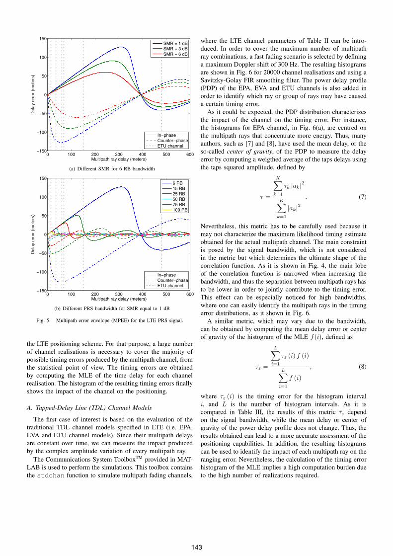
Considering (5) and (6), the MPEE is produced by meansof the maximum likelihood estimation and using a two-raymultipath model (i.e. LOS and multipath signal), as it isshown in Fig. 5. Firstly, the signal-to-multipath ratio (SMR) ischanged for the smallest PRS bandwidth, in Fig. 5(a), to assessthe impact of the multipath power. The results are obtained forthe destructive and constructive contribution of the multipath,that is, when the multipath ray is in-phase (solid line) andcounter-phase (dashed line), respectively. The taps delays ofthe ETU channel are also depicted (dotted line) to highlightthe multipath ray error for those delays. Secondly, the differentPRS bandwidth are tested for an SMR equal to 1 dB, in Fig.5(b), to confirm the multipath error reduction as the bandwidthincreases.
As it can be noticed, the maximum delay error producedby a single multipath ray can be found easily for differentscenarios with the multipath error envelope. Nevertheless, themultipath error assessment is more complicated in a realisticchannel due to the increase on the number of multipath rays.This observation suggests that another metric should be foundin order to measure the impact of a certain multipath channelon the time delay.
VI. TIMING ERROR HISTOGRAM
An alternative tool on the assessment of the multipath im-pact is the probability density function (PDF) of the time delayerror for a specific channel. The PDF of the timing error canhelp us to find the maximum error that bounds the accuracy of
142
0 100 200 300 400 500 600−150
−100
−50
0
50
100
150
Multipath ray delay (meters)
De
lay e
rro
r (m
ete
rs)
SMR = 1 dB
SMR = 3 dB
SMR = 6 dB
In−phase
Counter−phase
ETU channel
(a) Different SMR for 6 RB bandwidth
0 100 200 300 400 500 600−150
−100
−50
0
50
100
150
Multipath ray delay (meters)
De
lay e
rro
r (m
ete
rs)
6 RB15 RB
25 RB50 RB
75 RB100 RB
In−phase
Counter−phase
ETU channel
(b) Different PRS bandwidth for SMR equal to 1 dB
Fig. 5. Multipath error envelope (MPEE) for the LTE PRS signal.
the LTE positioning scheme. For that purpose, a large numberof channel realisations is necessary to cover the majority ofpossible timing errors produced by the multipath channel, fromthe statistical point of view. The timing errors are obtainedby computing the MLE of the time delay for each channelrealisation. The histogram of the resulting timing errors finallyshows the impact of the channel on the positioning.
A. Tapped-Delay Line (TDL) Channel Models
The first case of interest is based on the evaluation of thetraditional TDL channel models specified in LTE (i.e. EPA,EVA and ETU channel models). Since their multipath delaysare constant over time, we can measure the impact producedby the complex amplitude variation of every multipath ray.
The Communications System ToolboxTM provided in MAT-LAB is used to perform the simulations. This toolbox containsthe stdchan function to simulate multipath fading channels,
where the LTE channel parameters of Table II can be intro-duced. In order to cover the maximum number of multipathray combinations, a fast fading scenario is selected by defininga maximum Doppler shift of 300 Hz. The resulting histogramsare shown in Fig. 6 for 20000 channel realisations and using aSavitzky-Golay FIR smoothing filter. The power delay profile(PDP) of the EPA, EVA and ETU channels is also added inorder to identify which ray or group of rays may have causeda certain timing error.
As it could be expected, the PDP distribution characterizesthe impact of the channel on the timing error. For instance,the histograms for EPA channel, in Fig. 6(a), are centred onthe multipath rays that concentrate more energy. Thus, manyauthors, such as [7] and [8], have used the mean delay, or theso-called center of gravity, of the PDP to measure the delayerror by computing a weigthed average of the taps delays usingthe taps squared amplitude, defined by
τ =
K∑k=1
τk |ak|2
K∑k=1
|ak|2. (7)
Nevertheless, this metric has to be carefully used because itmay not characterize the maximum likelihood timing estimateobtained for the actual multipath channel. The main constraintis posed by the signal bandwidth, which is not consideredin the metric but which determines the ultimate shape of thecorrelation function. As it is shown in Fig. 4, the main lobeof the correlation function is narrowed when increasing thebandwidth, and thus the separation between multipath rays hasto be lower in order to jointly contribute to the timing error.This effect can be especially noticed for high bandwidths,where one can easily identify the multipath rays in the timingerror distributions, as it shown in Fig. 6.
A similar metric, which may vary due to the bandwidth,can be obtained by computing the mean delay error or centerof gravity of the histogram of the MLE f(i), defined as
τε =
L∑i=1
τε (i) f (i)
L∑i=1
f (i)
, (8)
where τε (i) is the timing error for the histogram intervali, and L is the number of histogram intervals. As it iscompared in Table III, the results of this metric τε dependon the signal bandwidth, while the mean delay or center ofgravity of the power delay profile does not change. Thus, theresults obtained can lead to a more accurate assessment of thepositioning capabilities. In addition, the resulting histogramscan be used to identify the impact of each multipath ray on theranging error. Nevertheless, the calculation of the timing errorhistogram of the MLE implies a high computation burden dueto the high number of realizations required.
143
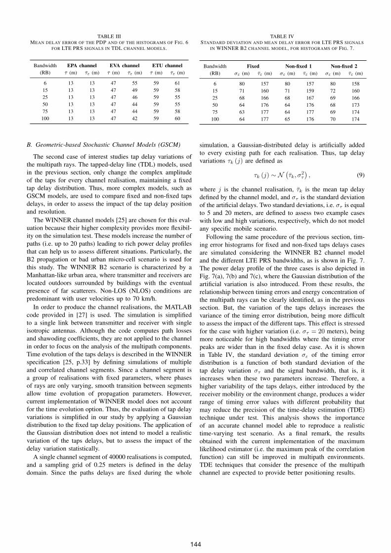
TABLE IIIMEAN DELAY ERROR OF THE PDP AND OF THE HISTOGRAMS OF FIG. 6
FOR LTE PRS SIGNALS IN TDL CHANNEL MODELS.
Bandwidth EPA channel EVA channel ETU channel(RB) τ (m) τε (m) τ (m) τε (m) τ (m) τε (m)
6 13 13 47 55 59 6115 13 13 47 49 59 5825 13 13 47 46 59 5550 13 13 47 44 59 5575 13 13 47 44 59 58100 13 13 47 42 59 60
B. Geometric-based Stochastic Channel Models (GSCM)
The second case of interest studies tap delay variations ofthe multipath rays. The tapped-delay line (TDL) models, usedin the previous section, only change the complex amplitudeof the taps for every channel realisation, maintaining a fixedtap delay distribution. Thus, more complex models, such asGSCM models, are used to compare fixed and non-fixed tapsdelays, in order to assess the impact of the tap delay positionand resolution.
The WINNER channel models [25] are chosen for this eval-uation because their higher complexity provides more flexibil-ity on the simulation test. These models increase the number ofpaths (i.e. up to 20 paths) leading to rich power delay profilesthat can help us to assess different situations. Particularly, theB2 propagation or bad urban micro-cell scenario is used forthis study. The WINNER B2 scenario is characterized by aManhattan-like urban area, where transmitter and receivers arelocated outdoors surrounded by buildings with the eventualpresence of far scatterers. Non-LOS (NLOS) conditions arepredominant with user velocities up to 70 km/h.
In order to produce the channel realisations, the MATLABcode provided in [27] is used. The simulation is simplifiedto a single link between transmitter and receiver with singleisotropic antennas. Although the code computes path lossesand shawoding coefficients, they are not applied to the channelin order to focus on the analysis of the multipath components.Time evolution of the taps delays is described in the WINNERspecification [25, p.33] by defining simulations of multipleand correlated channel segments. Since a channel segment isa group of realisations with fixed parameters, where phasesof rays are only varying, smooth transition between segmentsallow time evolution of propagation parameters. However,current implementation of WINNER model does not accountfor the time evolution option. Thus, the evaluation of tap delayvariations is simplified in our study by applying a Gaussiandistribution to the fixed tap delay positions. The application ofthe Gaussian distribution does not intend to model a realisticvariation of the taps delays, but to assess the impact of thedelay variation statistically.
A single channel segment of 40000 realisations is computed,and a sampling grid of 0.25 meters is defined in the delaydomain. Since the paths delays are fixed during the whole
TABLE IVSTANDARD DEVIATION AND MEAN DELAY ERROR FOR LTE PRS SIGNALS
IN WINNER B2 CHANNEL MODEL, FOR HISTOGRAMS OF FIG. 7.
Bandwidth Fixed Non-fixed 1 Non-fixed 2(RB) σε (m) τε (m) σε (m) τε (m) σε (m) τε (m)
6 80 157 80 157 80 15815 71 160 71 159 72 16025 68 166 68 167 69 16650 64 176 64 176 68 17375 63 177 64 177 69 174100 64 177 65 176 70 174
simulation, a Gaussian-distributed delay is artificially addedto every existing path for each realisation. Thus, tap delayvariations τk (j) are defined as
τk (j) ∼ N(τk, σ
2τ
), (9)
where j is the channel realisation, τk is the mean tap delaydefined by the channel model, and στ is the standard deviationof the artificial delays. Two standard deviations, i.e. στ is equalto 5 and 20 meters, are defined to assess two example caseswith low and high variations, respectively, which do not modelany specific mobile scenario.
Following the same procedure of the previous section, tim-ing error histograms for fixed and non-fixed taps delays casesare simulated considering the WINNER B2 channel modeland the different LTE PRS bandwidths, as is shown in Fig. 7.The power delay profile of the three cases is also depicted inFig. 7(a), 7(b) and 7(c), where the Gaussian distribution of theartificial variation is also introduced. From these results, therelationship between timing errors and energy concentration ofthe multipath rays can be clearly identified, as in the previoussection. But, the variation of the taps delays increases thevariance of the timing error distribution, being more difficultto assess the impact of the different taps. This effect is stressedfor the case with higher variation (i.e. στ = 20 meters), beingmore noticeable for high bandwidths where the timing errorpeaks are wider than in the fixed delay case. As it is shownin Table IV, the standard deviation σε of the timing errordistribution is a function of both standard deviation of thetap delay variation στ and the signal bandwidth, that is, itincreases when these two parameters increase. Therefore, ahigher variability of the taps delays, either introduced by thereceiver mobility or the environment change, produces a widerrange of timing error values with different probability thatmay reduce the precision of the time-delay estimation (TDE)technique under test. This analysis shows the importanceof an accurate channel model able to reproduce a realistictime-varying test scenario. As a final remark, the resultsobtained with the current implementation of the maximumlikelihood estimator (i.e. the maximum peak of the correlationfunction) can still be improved in multipath environments.TDE techniques that consider the presence of the multipathchannel are expected to provide better positioning results.
144

−40 −20 0 20 40 600
0.01
0.02
0.03
0.04
0.05
0.06
Timing error (meters)
PD
F
6 RB
15 RB
25 RB
50 RB
75 RB
100 RB
EPA delays
−40 −20 0 20 40 600
0.5
1
Tap delay (meters)
EP
A P
DP
(a) EPA channel model
−50 0 50 100 150 2000
0.01
0.02
0.03
0.04
0.05
0.06
Timing error (meters)
PD
F
6 RB
15 RB
25 RB
50 RB
75 RB
100 RB
EVA delays
−50 0 50 100 150 2000
0.5
1
Tap delay (meters)
EV
A P
DP
(b) EVA channel model
−50 0 50 100 150 200 2500
0.02
0.04
0.06
0.08
0.1
0.12
Timing error (meters)
PD
F
6 RB
15 RB
25 RB
50 RB
75 RB
100 RB
ETU delays
−50 0 50 100 150 200 2500
0.5
1
Tap delay (meters)
ET
U P
DP
(c) ETU channel model
Fig. 6. Timing error histograms of the MLE for TDL channel models.
−50 0 50 100 150 200 250 300 3500
0.01
0.02
0.03
0.04
Timing error (meters)
PD
F
6 RB
15 RB
25 RB
50 RB
75 RB
100 RB
Delays
−50 0 50 100 150 200 250 300 3500
0.5
1
Tap delay (meters)
PD
P
(a) Fixed taps delays
−50 0 50 100 150 200 250 300 3500
0.005
0.01
0.015
0.02
Timing error (meters)
PD
F
6 RB
15 RB
25 RB
50 RB
75 RB
100 RB
Delays
−50 0 50 100 150 200 250 300 3500
0.5
1
Tap delay (meters)P
DP
(b) Non-fixed taps delays (στ = 5 m)
−50 0 50 100 150 200 250 300 3500
0.002
0.004
0.006
0.008
0.01
0.012
0.014
Timing error (meters)
PD
F
6 RB
15 RB
25 RB
50 RB
75 RB
100 RB
Delays
−50 0 50 100 150 200 250 300 3500
0.5
1
Tap delay (meters)
PD
P
(c) Non-fixed taps delays (στ = 20 m)
Fig. 7. Timing error histograms of the MLE for WINNER B2 channel model.
145

VII. CONCLUSION
The impact of typical channel models, especially of theirmultipath propagation, on time delay estimation has beenassessed for the Long Term Evolution (LTE) positioningcapabilities. A two-ray multipath model has been used topreliminary evaluate the influence of the multipath power,multipath delay and signal bandwidth on the positioning error,by means of the multipath error envelope (MPEE). Due tothe limitations of this metric, a mean delay error (MDE)has been calculated from the timing error histogram of themaximum likelihood estimation (MLE), which is computedfor the traditional tapped-delay line (TDL) channel modelsspecified in LTE and for the WINNER channel model. It isshown that the MDE is function of the LTE signal bandwidth.It implicitly adds information of the signal characteristics,which are not traced by traditional metrics based on thechannel model. The state-of-the-art terrestrial channel modelsare intended for communications purposes, thus the tap delayposition is fixed, not having an important effect. However,assuming that the tap delay position might have an impacton the results of the ranging error distributions, the variationof the tap delay have also been analysed by adding as afirst approximation a Gaussian distribution on the tap-delayposition. Results show that the standard deviation of the timingerror distributions is a function of both standard deviation ofthe Gaussian-distribution of the taps delays and the signalbandwidth. Further evaluation of the multipath impact on thepositioning error could be done by realistically modellingthe time evolution of the taps delays derived from the usermovement in specific scenarios. In addition, the application oftechniques that consider the presence of the multipath channelis expected to improve the positioning accuracy obtained.
ACKNOWLEDGMENT
This work was supported by the European Space Agency(ESA) under the PRESTIGE programme ESA-P-2010-TEC-ETN-01 and by the Spanish Ministry of Science and Innova-tion project TEC 2011-28219.
REFERENCES
[1] 3GPP home page. [Online]. Available: http://www.3GPP.org[2] A. A. D’Amico, U. Mengali, and L. Taponecco, “TOA Estimation with
the IEEE 802.15.4a Standard,” IEEE Trans. on Wireless Communica-tions, vol. 9, no. 7, pp. 2238–2247, July 2010.
[3] P. Thevenon, S. Damien, O. Julien, C. Macabiau, M. Bousquet, L. Ries,and S. Corazza, “Positioning Using Mobile TV Based on the DVB-SHStandard,” in NAVIGATION, vol. 58, no. 2, Summer 2011, pp. 71–90.
[4] D. Serant, O. Julien, L. Ries, P. Thevenon, and M. Dervin, “The DigitalTV Case: Positioning Using Signals-of-Opportunity Based on OFDMModulation,” Inside GNSS, Nov./Dec. 2011.
[5] J. Medbo, I. Siomina, A. Kangas, and J. Furuskog, “Propagationchannel impact on LTE positioning accuracy: A study based on realmeasurements of observed time difference of arrival,” in Proc. IEEEPIMRC ’09, Sep. 2009, pp. 2213–2217.
[6] A. Dammann, E. Staudinger, S. Sand, and C. Gentner, “Joint GNSSand 3GPP-LTE based positioning in outdoor-to-indoor environments -performance evaluation and verification,” in Proc. ION GNSS, Sep. 2011.
[7] R1-092307, “Analysis of UE Subframe Timing Offset MeasurementSensitivity to OTDoA Performance,” 3GPP, Alcatel-Lucent, RAN1-57bis, June 2009.
[8] C. Mensing and A. Dammann, “Positioning with OFDM based commu-nications systems and GNSS in critical scenarios,” in Proc. WPNC ’08,Mar. 2008, pp. 1–7.
[9] W. Wang, T. Jost, A. Lehner, F. Perez-Diaz, and U.-C. Fiebig, “Towardsa Channel Model for Joint GNSS and Mobile Radio Based Positioning,”in COST Action IC1004, Oct. 2011.
[10] J. A. Del Peral-Rosado, J. A. Lopez-Salcedo, G. Seco-Granados,F. Zanier, and M. Crisci, “Preliminary analysis of the positioningcapabilities of the positioning reference signal of 3GPP LTE,” in Proc.5th Eur. Workshop on GNSS Signals and Signal Processing, Dec. 2011.
[11] 3GPP TS 36.305, Stage 2 functional specification of User Equipment(UE) positioning in E-UTRAN, Std.
[12] 3GPP TS 36.211, Physical Channels and Modulation, Std.[13] J. A. Del Peral-Rosado, J. A. Lopez-Salcedo, G. Seco-Granados,
F. Zanier, and M. Crisci, “Achievable Localization Performance Ac-curacy of the Positioning Reference Signal of 3GPP LTE,” in Proc.International Conf. on Localization and GNSS (ICL-GNSS), June 2012.
[14] ITU-R M.1225 International Telecommunication Union, “Guidelines forevaluation of radio transmission technologies for IMT-2000,” 1997.
[15] 3GPP TS 05.05, Radio transmission and reception, Std.[16] R4-070572, “Proposal for LTE channel models,” 3GPP, Ericsson, Nokia,
Motorola, Rohde & Schwarz, RAN4-43, May 2007.[17] T. Sorensen, P. Mogensen, and F. Frederiksen, “Extension of the ITU
channel models for wideband (OFDM) systems,” in Proc. IEEE VTC’05, vol. 1, Sept. 2005, pp. 392–396.
[18] 3GPP TS 36.101, User equipment (UE) radio transmission and recep-tion, Std.
[19] 3GPP TS 36.104, Base station (BS) radio transmission and reception,Std.
[20] R4-060334, “LTE Channel Models and simulations,” 3GPP, Ericsson,Elektrobit, Nokia, Motorola, Siemens, RAN4-38, Feb. 2006.
[21] A. Molisch, H. Asplund, R. Heddergott, M. Steinbauer, and T. Zwick,“The COST259 Directional Channel Model-Part I: Overview andMethodology,” IEEE Trans. on Wireless Communications, vol. 5, no. 12,pp. 3421–3433, Dec. 2006.
[22] L. Correia, Ed., Mobile Broadband Multimedia Networks. AcademicPress, 2006.
[23] R. Verdone, Ed., COST 2100 - Pervasive Mobile and Ambient WirelessCommunications. Berlin, Germany: Springer, 2011.
[24] 3GPP TS 25.996, Spatial Channel Model for Multiple Input MultipleOutput (MIMO) Simulations, Std.
[25] Commission of the European Communities, IST-WINNER II projectdeliverable D1.1.2, WINNER II Channel Models, Std.
[26] ITU-R M.2135-1 International Telecommunication Union, “Guidelinesfor evaluation of radio interface technologies for IMT-Advanced,” 2008.
[27] L. Hentila, P. Kyosti, M. Kaske, M. Narandzic, and M. Alatossava,“MATLAB implementation of the WINNER Phase II Channel Modelver1.1,” IST-WINNER II Project, Dec, 2007.
146