evolving architecture for adaptabilityluluo/courses/practicum1-luo.pdf · evolving architecture for...
TRANSCRIPT

Evolving Architecture for Adaptability
ISRI Practicum Report I May 18, 2003
Lu Luo Institute for Software Research International
School of Computer Science Carnegie Mellon University

1
Evolving Architecture for Adaptability (ISRI Practicum Report I)
Lu Luo Institute for Software Research International
School of Computer Science Carnegie Mellon University
May 18, 2003
Abstract Software development methodologies are confronted with frequently changing customer needs and rapidly developing technologies. It is critical for an organization to minimize the design cost and time to market of its software products, through innovation in technical, business, and organizational aspects. In this report, I present an industrial case study on a startup company that has successfully built an adaptable software framework to address different customer needs. As a reflection of this study, I present several real-world software engineering issues in hope to provide useful ideas for future reference. This report is submitted to the Institute for Software Research International of School of Computer Science at Carnegie Mellon University, to partially fulfill the practicum requirements of the PhD program in software engineering. 1. Introduction Traditional software engineering strategies are challenged in industrial organizations where the technology is subject to rapid evolution and the requirements are still emerging. Typical examples of such challenges reside in the area of mobile/wearable computing, where the computing and communication environments are heterogeneous and complex. It is useful to study how software should be developed in order to facilitate the organization’s business needs. In this report, I present an industrial case study that address and discuss a series of software engineering issues that are derived from the author’s experience at a startup company that provides customized software solutions to customers in need of mobile computing support. For the sake of nondisclosure, the identity of the target organization is shielded, and will be mentioned as “Company A” in the rest part of the report. The mission of Company A has been motivated by and benefited from the fundamental changes that increasing computing power and wireless communication can bring to the ways people work. Under traditional environments, workers involved in the maintenance or operation of large vehicles such as tanks and aircrafts, or portions of the infrastructure such as bridges and oil rigs, have great difficulty in using computers to support their working process. The object being maintained or operated is usually very large, and the worker must operate on it in situ, outside or in special structures. The fast-growing popularization of wireless infrastructure and portable computing devices enable the computer support for front line workers. For example, when the worker is performing some industrial process, instead of referring to paper-formed technical manuals, or leaving the work site to consult people in the back office, the steps of this process can be displayed on the worker’s mobile computer. As the environment in which the process is being performed may be dangerous or cramped, it is very helpful when the worker is equipped with such computing devices while both his/her hands are free to engage in the operation.

2
The major challenges that Company A faces are to develop complex enterprise solution for different customers who are in need of various mobile/wearable support, and to deliver the solution in a competitively shorter time-to-market. The adaptation of business focus to the marketplace combined with the immaturity of mobile computing technologies, are the driving factors in the company behavior. The uniqueness of Company A’s business mode brings several interesting questions for software engineering practitioners. What strategies should be deployed to best address the changing customer requirements? How do you choose the right software engineering techniques to leverage the company’s business needs? What are the influences of the business and technologies on the organization? I intend to address these questions in this report based on the author’s experience with the company and subsequent follow-ups. I focus on reflecting on the practical software engineering issues and the lessons learned, in hopes of providing “portable” conclusions useful in similar situations elsewhere. The report is organized as follows: Section 2 gives the background information about the author’s experience, including the background of the company and the evolution of the product line. In Section 3, I discuss software engineering issues arising from reflection on the experience. Section 4 summarizes the report and proposes some potential research directions. 2. Description of Experience This case study is derived from the author’s four-month experience working as a student consultant with Company A. Though the experience is comparably short, the author is able to access adequate information for this report from follow-ups including interviewing relevant personnel and studying the company’s technical documentation. 2.1 Organization Background Company A is formed in 1995 as an outgrowth of the Wearable Computing Project at Carnegie Mellon University (CMU). Originated in the early 1990s from a summer course, the CMU Wearable Group has been building and researching wearable computer systems to support maintenance, manufacturing, and collaborative tasks. By 1995, being one of the pioneer groups in this new field, the CMU Wearable Group had successfully built several generations of wearable computer systems, which quickly attracted many requests for customized wearable systems from various customers. The growth of customer needs had exceeded the scope and ability of a university research group. Therefore, Company A was founded, taking over from the Wearable Group those requests and contracts that were not intensively research-oriented. The initial contracts of Company A were from several fixed customers such as the US government. During this initial period, the company operates as a solution factory, producing one-of-a-kind solution for each customer. Each solution is developed as a prototype and then produced as a stovepipe application. For each different customer, the requirement, architecture, and design of a new solution had to be built from scratch, which required a fairly large engineering team and took significant amounts of development time (in the tens of person years). Focusing only on customizing stovepipe solutions for specific customers does not allow Company A to be more competitive in product cost and time-to-market. By the end of 2000, a general framework of reusable software components, which will be mentioned as “Architecture L” in this report, is constructed and deployed by Company A’s technical team. Architecture L is based on the Java 2 Enterprise Edition (J2EE) component-based technologies of Sun Microsystems. The intention of building this architecture framework is to provide a general solution for future products regardless of specific customer needs. The L framework is composed of a series of highly reusable components, some of which are reconstructed from previous products. Instead of devoting the limited technical strength to developing products according to each specific customer’s requirements at a time, this framework enables a family of solution schemes for

3
potential customers to choose from, aw well as rapid construction of customized products. The adoption of Architecture L is proved to successfully address the changing customer needs and promotes potential business opportunities of Company A. After the completion of the L framework, the company has greatly expanded the scope of its business and attracted several important new customers. In summary, the evolution of Company A’s major technical and business focuses can be divided into three phases:
Initial Phase (1995 ~ 1999): Initial government contracts inherited from the Wearable Group. The company’s focuses during this period are highly prototype-oriented, point products. Evolution Phase (1999 ~ 2001): Construction of Architecture L for current and future products. Seek new customers while keep providing products and services to existing ones. Current Phase (2001 ~ present): Common architecture is complete. Reusable components framework is built. Start to acquire new customers.
2.2 The Post-L Product Family Based on the framework of Architecture L, Company A provides a product line of software solutions that enables frontline workers to access electronic technical support from either operation manuals or experiential personnel in the back office, depending on different customer requirements. The product family enables customers to create a collaborative environment, provides real-time visibility to operations, and helps develop a rich, historical archive. The solution family can be divided into two major categories, namely solutions M and P. The M solution is the core technology behind the revolutionary changes that customers are experiencing in maintenance performance. M enables frontline workers to exchange information with local or remote experts, supervisors and managers. It includes on-line chat and electronic white-board for displaying photos, drawings, and diagrams that are needed to resolve technical problems the workers may encounter. It also provides a collective and continually growing archive of frontline worker knowledge and expertise for the entire enterprise, promoting best-of-breed maintenance practices. Solution M makes it easy to regulate the structure of the input of maintenance incident reports. The P solution is a standalone yet a complementary product to M. P dynamically distributes and displays technical content to different frontline workers from a singular source to maximize efficiency. Technical content is either converted from legacy documentation or created using Interactive Electronic Technical Manuals (IETMs) authoring tools and then stored in an XML repository for flexible usage. P ties easily into existing legacy systems and updates incremental changes to technical manuals to ensure data is current. Content changes can be made in one location and propagate to all deployments via wide area and wireless networks. In addition to M and P, the product line includes other products that facilitate the major application areas. These ancillary products enable data and application management, and provide easy access to other managerial information such as the team situation and network condition. This entire product line of Company A covers a very large scope of customer needs in providing support to frontline workers, yet are very flexible for customization based on different requirements. For each specific customer, the company provides consulting services including domain and technical expertise necessary to customize the customer’s project from the planning stages through implementation. Each customized solution is built from the basic components in the product family framework, yet is specific to the customer. A five-step component methodology is used to build each customized solution:

4
Step 1: Assessment. The company’s Consulting Service team works with the customer to gain an intimate understanding of how the customer’s enterprise operates. The customer’s needs are assessed and a direction for a solution is defined.
Step 2: Proposal. Based on the results of the assessment, the company crafts a plan of action tailored to the customer’s needs. The proposal includes the details of the plan, objectives, milestones and deliverables.
Step 3: Build. The Solutions and Technology team of Company A are utilized to execute the proposal and create the solution for the customer. Once the solution is created, the company will help the customer test and configure the system to their specifications.
Step 4: Transition. The company prepares the customer for the implementation of the solution, including integration with legacy applications and training, to make sure that the introduction of new technology goes smoothly.
Step 5: Implementation. The solution is implemented across the customer’s enterprise and the company’s Consulting Service team continues to answer questions and provide guidance as the customer makes the transition.
2.3 Description of Experience From January to May of 2002, the author worked as a student consultant at Company A. During this period, the company’s Solutions and Technical team is in the process of constructing the set of necessary components for the P solution. The author took part in various phases including analysis, re-design, and development of one of the major components of P: the Interpreter. The ultimate goal of the P solution is to make technical manuals conveniently viewable to the worker in situ, and to provide interactive instructions and recording functionalities. For desktop systems, a long time ago, the display of technical manuals and support information has migrated from paper to electronic documents. Limited by facts like display size and working environment, mobile solutions for viewing electronic documents require richer forms of user interaction, rather than just displaying lines of text or illustrations. Company A’s P solution primarily supports the emerging IETM technology, which offers richer forms of interaction and a more satisfying user experience. IETM technology is still in its infancy, with conflicting standards existing across companies in the industry. It is not likely that when one or a few unified IETM standards will soon be defined. The P solution family provides the environment for displaying technical manuals on a variety of heterogeneous mobile computing devices. One of the key ideas is the use of a pluggable Interpreter to support different types of IETMs. In addition, the display system provides the overriding context for interacting with the IETM. For instance, it defines a set of states and interaction metaphors that are common to all IETMs, such as “navigating the table of contents” or “placing an electronic bookmark.” The display system also provides a framework for hosting Interpreters, and defines Application Programming Interfaces (APIs) that all Interpreters must implement. For each IETM type, an Interpreter should be written. Basically, the job of the Interpreter is to accept IETMs of the corresponding type and make the contents available to the technical manual display system in well-defined ways. More specifically, the Interpreter must navigate the IETM and apply the authored behavior to the authored content, based on the semantics of the underlying language specific to the IETM type. The author’s work was to design and implement one part of the Interpreter for a specific type of IETM. This experience can be divided into four phases.

5
Phase 1: Get familiar with the architecture of the technical manual display system and the framework for plug-able Interpreters. The outcome is a requirements analysis document for the plug-able Interpreter module. Provide the technical team with feedback and suggested design modifications for the framework. Contribute to the design of the architecture framework depending on the state of development when this project commences. Phase 2: Complete the design of the Interpreter component with help from the Technical team. The outcome is a fully documented design followed by a peer review. The design is modeled using modern OOA/OOD 1 techniques, including UML 2 class and sequence diagrams.
Phase 3: Complete the implementation of the Interpreter component. Outcome is a fully functioning module that cooperates seamlessly with other components.
Phase 4: Perform a rigorous testing and evaluation of the implementation followed by documentation.
Besides the development work, the main purpose of the author is to observe and reflect on the Technical team as well as the entire company’s software engineering practice. Therefore, close attention has been paid to the organizational structure and development processes of Company A, which will be discussed in detail in Section 3. 3. Reflection In this section, I discuss several software engineering issues as a reflection of this case study. The discussion will be around the following questions:
What strategies should be deployed to best address the changing customer
requirements? How to choose the right software engineering techniques to leverage the company’s
business needs?
What are the influences of the marketplace and technologies on the organization? 3.1 Evolving Architecture towards Adaptability At the beginning of its startup, Company A focuses on government contracts inherited from the CMU Wearable Group. The targeted user, application and working environment of these contracts are specific to the corresponding government projects, each differing from one another. During this period, Company A can be viewed as a solution factory, producing one of a kind solution for a specific customer. Each solution is developed as a prototype and then produced as a stovepipe application. For each different customer, the requirement, architecture, and design of a new solution had to be built from scratch. During this period, although the Engineering team of Company A was composed of highly experienced and sophisticated software developers, each stovepipe solution required a fairly large engineering team and took significant amounts of development time (in the tens of person years). The funding from government contracts has kept Company A running in a fairly balanced manner during its first couple of years of business. However, the resource drain on maintaining and re-
1 Object-Oriented Design and Object-Oriented Analysis 2 Unified Modeling Language

6
engineering the stovepipe solutions prevented the company from easily expending into new markets to increase its revenue base. If most of the engineering effort were to be put into redesigning a new solution for a new customer, there would be no space and time left for creating innovative, competitive, and cost-effective solutions for other customers. With the growing customer base need, it is essential for the company to create a general solutions family that could be quickly tailored to a customer’s needs. The architecture of the existing stovepipe solutions cannot satisfy this growing requirement. Two sets of complementary requirements define the design of the general architecture. First, based on the architecture, the applications to be built are enterprise applications for field service workers. Being directly visible to customers, any failure to meet this set of requirements results in possible discontent or more seriously, loss of customers whose expectations are not satisfied. The second set requires that the architecture should be common to all future solutions that Company A provides. This set of requirements only influences the customers indirectly, but it affects more fundamental aspects of the company’s business. Failure or difficulty to integrate the application to the customer’s environment takes more time and/or cost more money for the vender. More importantly, a common architecture directly affects the architects, the developers, and therefore ultimately the business. The use of a common product architecture framework decreases use of resources, the amount of time and effort required to create new applications or enhance existing ones, the speed of bringing products to market, and the speed of incorporating new technologies into products. If the common architecture is designed to meeting the second set of requirements, the company’s future business will be enhanced efficiently by improving the method of developing products and the quality of the products themselves. By the end of 2000, the Engineering team of Company A has finished constructing Architecture L, a general software architecture framework for the company’s future product family. The overall structure of a solution built on L is shown in Figure 1. Essentially, the solution contains three main elements: the user interface, the application, and the components.
Browser-BasedUser Interface
Custom Web-Based
User Interface
Application
Component
DataBaseData Flow
Figure 1. Structure of an L Application
User Interface:
Company A sends a group of domain experts, cognitive psychologists and graphic artists to work with several clients to understand various customer needs and constraints. Then, the initial design of the Design Team, including a storyboard, screen shots and a prototype of the overall user interface, is converted to a working user interface on real devices. This allows the architecture to support the integration of custom user experiences, and enables creation of common portions and reuse of software. To turn user experience designs into a general framework of working user interfaces, a variety of client devices with different screen sizes, operating systems and input modalities must be supported. The architecture addresses this by adopting two types of interfaces and supporting flexible interface adaptability for different customers. To minimize the development resources, interfaces devices are sorted into

7
classes according to their characteristics and solutions of different fidelities are created for each class. This approach is unique compared to how user interfaces are developed for other web-based applications, and is a core aspect of the company’s business and essential to the adaptability of the architecture. Applications
An L application is responsible for uniting the system into a functional entity. It provides the user interfaces an API to extend the system features to an end user. The application layer ties together m components and exposes the aggregated functionality to n user interfaces. Each user interface decides what and how functionality is exposed to the end users. In order to rapidly develop and deploy each solution, the application layer is kept as thin as possible by delegating the bulk of the business work to components. Application code is moved into a component as far as its functionality is reusable. If a piece of functionality is not likely to be reused, it is incorporated into the application. An L application is not a large, one-size-fits-all product but a thin layer that ties together components to provide the functionality required for a specific solution. The modifiability and extensibility attributes of the application are emphasized. Customization is localized to the application layer, reducing the amount of custom code. Components are not customized, allowing greater reuse and less maintenance costs. Components
The components in Architecture L are the primary part for reuse. A library of components is created and applications can be easily synthesized in short periods of time to create specialized solutions for specific customers. The library contains core components related to the client-server frameworks of L, domain specific components such as maintenance, repair, and overhaul, and generalized utility components such as security, authorization, and user management. With this library, the development of applications simply becomes an exercise in creating business logic that composes the necessary set of capability components into a customized solution for the customer. This type of engineering significantly reduces the development time of an application when compared with the creation of stovepipe applications. It also significantly reduces resources needed for post deployment support of the solutions. This allows the company to create products and systems that meet increasingly shorter times-to-market, therefore more competitive in its large markets.
In summary, the Architecture L framework is based on state-of-the-art software engineering and programming technology. It allows customized solutions to be easily and rapidly developed and deployed. A new user interface can be created without changing the application or component layer at all. A new implementation of a component can be integrated into the system without affecting the user interfaces or the application layer. New functionality can be added to the system by incorporating another component, adding the necessary API methods to the application layer, and adding new features to each user interface to expose the new functions. Over time, the library of components of L has grown and allowed the rapid creation of new solutions for customers in existing markets as well as the tailoring of existing systems to create prototypes for potential new customers. As a result of the architectural innovation, the company actually has gained four major customers and a total of over $6 million from product and professional services and investment in the year since the successful construction of the architecture framework without requiring any additional personnel for the Technical team. Additionally, the company has expanded its European branch
8
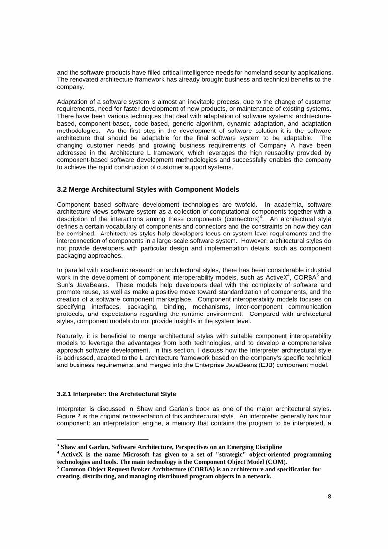
and the software products have filled critical intelligence needs for homeland security applications. The renovated architecture framework has already brought business and technical benefits to the company. Adaptation of a software system is almost an inevitable process, due to the change of customer requirements, need for faster development of new products, or maintenance of existing systems. There have been various techniques that deal with adaptation of software systems: architecture-based, component-based, code-based, generic algorithm, dynamic adaptation, and adaptation methodologies. As the first step in the development of software solution it is the software architecture that should be adaptable for the final software system to be adaptable. The changing customer needs and growing business requirements of Company A have been addressed in the Architecture L framework, which leverages the high reusability provided by component-based software development methodologies and successfully enables the company to achieve the rapid construction of customer support systems. 3.2 Merge Architectural Styles with Component Models Component based software development technologies are twofold. In academia, software architecture views software system as a collection of computational components together with a description of the interactions among these components (connectors)3. An architectural style defines a certain vocabulary of components and connectors and the constraints on how they can be combined. Architectures styles help developers focus on system level requirements and the interconnection of components in a large-scale software system. However, architectural styles do not provide developers with particular design and implementation details, such as component packaging approaches. In parallel with academic research on architectural styles, there has been considerable industrial work in the development of component interoperability models, such as ActiveX4, CORBA5 and Sun’s JavaBeans. These models help developers deal with the complexity of software and promote reuse, as well as make a positive move toward standardization of components, and the creation of a software component marketplace. Component interoperability models focuses on specifying interfaces, packaging, binding, mechanisms, inter-component communication protocols, and expectations regarding the runtime environment. Compared with architectural styles, component models do not provide insights in the system level. Naturally, it is beneficial to merge architectural styles with suitable component interoperability models to leverage the advantages from both technologies, and to develop a comprehensive approach software development. In this section, I discuss how the Interpreter architectural style is addressed, adapted to the L architecture framework based on the company’s specific technical and business requirements, and merged into the Enterprise JavaBeans (EJB) component model. 3.2.1 Interpreter: the Architectural Style Interpreter is discussed in Shaw and Garlan’s book as one of the major architectural styles. Figure 2 is the original representation of this architectural style. An interpreter generally has four component: an interpretation engine, a memory that contains the program to be interpreted, a
3 Shaw and Garlan, Software Architecture, Perspectives on an Emerging Discipline 4 ActiveX is the name Microsoft has given to a set of "strategic" object-oriented programming technologies and tools. The main technology is the Component Object Model (COM). 5 Common Object Request Broker Architecture (CORBA) is an architecture and specification for creating, distributing, and managing distributed program objects in a network.

9
representation of the control state of the interpretation engine, and a representation of the current state of the program being simulated. Basically, in an interpreter organization, a virtual machine is produced in software.
Programbeing
interpretedData
(program state)
Simulatedinterpretation
engine
Internalinterpreter
state
Inputs
Outputs Selected instrustion
Selected data
Memory
Computation(state machine)
Data Access(fetch/store)
Figure 2. Architectural Style: Interpreter
Interpreters are commonly used to build virtual machines that close the gap between the computing engine expected by the semantics of the program and the computing engine available in hardware. The Technical team of Company A adopts this architectural style for one of the sub modules of the P product. At the architectural level, the overall system properties are determined by the style. It is the Technical team’s job to put more details into the architectural design for the Interpreter component in the P solution family. The requirements and considerations of the Interpreter component design are explained in the following section.
3.2.2 Interpreter: the Component Design Compared with the architectural style, the actual design for the Interpreter has to take into consideration many requirements and restrictions and has to be adaptable to heterogeneous customer needs. The P solution family is intended to display conventional technical manuals as well as IETMs on mobile devices for different customers. The manuals may come from various resources and may be authored according to a variety of different standards. The display system may be authored accessible from a variety of different computing devices, including portable, mobile and wearable computer systems. The appearance of the manual is not dictated solely by the authored content and may vary according to the interface characteristics of the client device. The display system supports different ITEM types through the use of plug-able interpreters that adhere to a uniform interface. Although the display system may be used to view a wide variety of technical manuals of various types, it provides a standard framework and context for doing so. In particular, it introduces a set of states, metaphors, and operations that are supported by all manuals. Figure 3 illustrates the top-level architecture design for solution P. The Interpreter component is highlighted in gray.
10
User Input
Controller
ManualNavigation
Information
StateNavigation
Interpreter
Navigation
Context
View Generation
State Logic DisplayGenerator
State NavigationInput
Manual NavigationInput
Information Input
State
Content
View
Structure Behavior
Manual Content
Manual
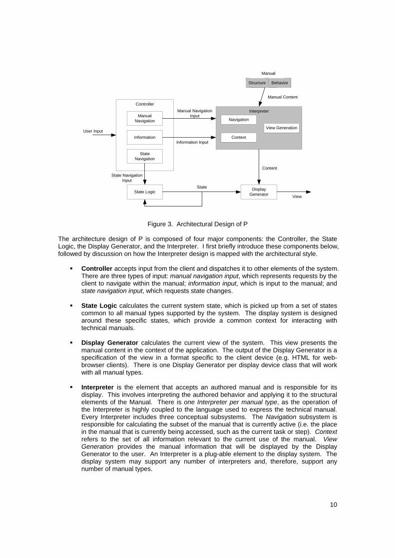
Figure 3. Architectural Design of P The architecture design of P is composed of four major components: the Controller, the State Logic, the Display Generator, and the Interpreter. I first briefly introduce these components below, followed by discussion on how the Interpreter design is mapped with the architectural style.
Controller accepts input from the client and dispatches it to other elements of the system. There are three types of input: manual navigation input, which represents requests by the client to navigate within the manual; information input, which is input to the manual; and state navigation input, which requests state changes.
State Logic calculates the current system state, which is picked up from a set of states
common to all manual types supported by the system. The display system is designed around these specific states, which provide a common context for interacting with technical manuals.
Display Generator calculates the current view of the system. This view presents the
manual content in the context of the application. The output of the Display Generator is a specification of the view in a format specific to the client device (e.g. HTML for web-browser clients). There is one Display Generator per display device class that will work with all manual types.
Interpreter is the element that accepts an authored manual and is responsible for its
display. This involves interpreting the authored behavior and applying it to the structural elements of the Manual. There is one Interpreter per manual type, as the operation of the Interpreter is highly coupled to the language used to express the technical manual. Every Interpreter includes three conceptual subsystems. The Navigation subsystem is responsible for calculating the subset of the manual that is currently active (i.e. the place in the manual that is currently being accessed, such as the current task or step). Context refers to the set of all information relevant to the current use of the manual. View Generation provides the manual information that will be displayed by the Display Generator to the user. An Interpreter is a plug-able element to the display system. The display system may support any number of interpreters and, therefore, support any number of manual types.
11
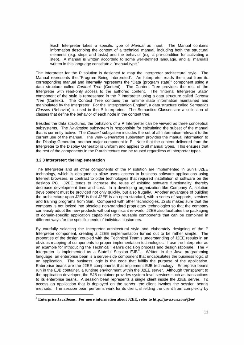
Each Interpreter takes a specific type of Manual as input. The Manual contains information describing the content of a technical manual, including both the structural elements (e.g. steps and tasks) and the behavior (e.g. a pre-condition for activating a step). A manual is written according to some well-defined language, and all manuals written in this language constitute a “manual type.”
The Interpreter for the P solution is designed to map the Interpreter architectural style. The Manual represents the “Program Being Interpreted”. An Interpreter reads the input from its corresponding manual and internally represents the “Data (program state)” component using a data structure called Content Tree (Content). The Content Tree provides the rest of the Interpreter with read-only access to the authored content. The “Internal Interpreter State” component of the style is represented in the P Interpreter using a data structure called Context Tree (Context). The Context Tree contains the runtime state information maintained and manipulated by the Interpreter. For the “Interpretation Engine”, a data structure called Semantics Classes (Behavior) is used in the P Interpreter. The Semantics Classes are a collection of classes that define the behavior of each node in the content tree. Besides the data structures, the behaviors of a P Interpreter can be viewed as three conceptual subsystems. The Navigation subsystem is responsible for calculating the subset of the manual that is currently active. The Context subsystem includes the set of all information relevant to the current use of the manual. The View Generation subsystem provides the manual information to the Display Generator, another major component in P. Note that the content delivered from the Interpreter to the Display Generator is uniform and applies to all manual types. This ensures that the rest of the components in the P architecture can be reused regardless of Interpreter types. 3.2.3 Interpreter: the Implementation The Interpreter and all other components of the P solution are implemented in Sun’s J2EE technology, which is designed to allow users access to business software applications using Internet browsers, in contrast to older technologies that required installation of software on the desktop PC. J2EE tends to increase the reuse of existing software functionality, thereby decrease development time and cost. In a developing organization like Company A, solution development must be provided not only quickly, but also frugally. Another advantage of building the architecture upon J2EE is that J2EE is an open standard, with a series of supports, services and training programs from Sun. Compared with other technologies, J2EE makes sure that the company is not locked into obsolete non-standard proprietary technologies so that the company can easily adopt the new products without significant re-work. J2EE also facilitates the packaging of domain-specific application capabilities into reusable components that can be combined in different ways for the specific needs of individual customers. By carefully selecting the Interpreter architectural style and elaborately designing of the P Interpreter component, creating a J2EE implementation turned out to be rather simple. The properties of the design coupled with the Technical Team’s understanding of J2EE results in an obvious mapping of components to proper implementation technologies. I use the Interpreter as an example for introducing the Technical Team’s decision process and design rationale. The P Interpreter is implemented as a Stateful Session EJB 6 . Written in the Java programming language, an enterprise bean is a server-side component that encapsulates the business logic of an application. The business logic is the code that fulfills the purpose of the application. Enterprise beans are the J2EE components that implement EJB technology. Enterprise beans run in the EJB container, a runtime environment within the J2EE server. Although transparent to the application developer, the EJB container provides system-level services such as transactions to its enterprise beans. A session bean represents a single client inside the J2EE server. To access an application that is deployed on the server, the client invokes the session bean's methods. The session bean performs work for its client, shielding the client from complexity by 6 Enterprise JavaBeans. For more information about J2EE, refer to http://java.sun.com/j2ee/

12
executing business tasks inside the server. As its name suggests, a session bean is similar to an interactive session. A session bean is not shared – it may have just one client, in the same way that an interactive session may have just one user. Since the Interpreter needs to track the current state of both the Content and Context data to decide the current display content, apparently a Stateful Session EJB is the most logical implementation choice. There have been some rationales and tradeoffs in the context of using J2EE. Although the J2EE environment provides the designer with some flexibility, allowing designers to make choices, especially when designing a component, there are many design decisions constraint by the rules and structure of J2EE. Secondly, implementations of the J2EE specification provide many beneficial but complex services. Developers have to fully understand the J2EE environment to avoid conceptual mistakes. For large systems, considerable problems with performance, scalability and reusability may arise. I will cover a bit more of this topic in later sections. 3.2.4 Summary In this section, I introduced three stages of the design and implementation for the P solution, using the Interpreter component as an example. This engineering effort combined the advantages of software architectural style and component interoperability models and turned out to be a successful practice. The architectural style is not only nice in theory, but also proved helpful in practice. Based on the basic L framework, the design of the P Interpreter component started with analyzing and adopting the Interpreter architectural style. Ensuring that the system-level properties addressed in the Interpreter architectural style fit the need of the requirements of the P solution, a detailed architectural design is created, closely coupling the entire L framework and the backbone J2EE technology. Given the design, it was very straightforward to implement the P Interpreter component using J2EE. Although I did not discuss how the Interpreter component was deployed in the entire P system, it is actually as effortless as it should be. This successful practice is a good example of applying the advanced results of academic research to real world solutions, in combination with state-of-the-art industrial technologies. 3.3 Discussions on Patterns Company A’s Technical Team features a close coupling with the Core J2EE Patterns throughout the post-L development process. As the L framework is based on J2EE, it is natural that the designers keep taking the supports and features that come along with the technology. J2EE patterns are a collection of J2EE based solutions to common problems that reflect the collective expertise and experience of Java technology. Basically, a core J2EE pattern can be classified into three logical architectural tiers: Presentation, Business, and Integration, with detailed functionality categories. These patterns describe typical problems encountered by enterprise application developers and the solutions to these problems. The L framework and its components make use of many relevant J2EE patterns. In this section, I focus on discussing how the company has benefited from applying patterns in the development, both technically and organizationally. Most of the discussion is based on the author’s experience as a new developer with limited background information and skills. 3.3.1 Benefits I first discuss the benefits that using patterns brings to Company A’s development practice.
Component Reuse Patterns capture the essence of working designs in a form that makes them usable in future work, including specifics about the context that makes the patterns applicable or not. As I have mentioned in previous sections, prior to the L framework, there have been numerous stovepipe products created to satisfy different customer needs. Architecture L constructs the

13
top-level framework that clearly divides the existing modules into the three functional layers in L. However, the heterogeneous nature of the existing modules makes it very difficult to create the detailed design for each product family, as well as the components. Fortunately, there are adequate J2EE patterns that can be referred to when constructing these components. For example, the P Interpreter takes great advantage of the instructions provided in the Java Interpreter pattern. Given the complete framework of interface, structure, configuration and deployment that are defined and explained the pattern, all that developers need to do is to fill in the functionalities. It also makes it easy to reuse the preexisting functional modules inherited from pre-L products. Patterns also serve as risk mitigators in the sense of providing components that are already proven in practice. It reduces discovery costs as well as software scrap and rework. Design Rationale
Patterns are the media of expression of experience. It is often the case that developers do not know why a design was the way it was. No one bothered writing down the reasons for each major change to the design, let alone the incremental ones. As a result, reverse engineering of the design choices has to be done time and again, false starts, iteration, and delays were the norm. Although these recurrences are somewhat beneficial, they often reflect the shallow design rationale of most development teams. Patterns promote development team to clarify their design rationales. Patterns help designers focus their thinking so that they could more readily identify designs based on what is needed to do. It offers something concrete to explain designs. If I use the P Interpreter as an example, the instructions on Java Interpreter pattern help the developers a lot on the detailed data organization, object structure, as well as implementation details. After developers understand a handful of patterns, when they discuss problems, they can quickly discover the complexity of architecture by asking which patterns apply. Communication and Documentation
The biggest payoff of using patterns is the high level of communication designers can achieve. With the general vocabulary defined in the patterns, designs are discussed not in terms of classes, objects and methods, but to a great extent in terms of design patterns concepts: participants, applicability, consequences, and tradeoffs. Developers become productive more quickly within the culture of existing patterns and frameworks. At the beginning of working with Technical Team of Company A, the author experienced a short period of frustration since the rest of the team talked in a way that the author “could not understand”, i.e. the pattern terms. But after the author learned a couple of core Java patterns, it became fairly easy to communicate and discuss with other team members using the concepts defined in patterns. Achieving more knowledge of patterns, it also became easier for the author to understand existing designs that are expressed in terms of patterns. The ambiguity that could be brought by inefficient communication is to some extent amended by using patterns. The core Java patterns intensively uses UML7 for documentation, which closely matches the common design language that most development organizations use today. The pattern catalog is composed of Class Diagrams, which show the structure of the pattern solution and the structure of the implementation strategies and provide the static view of the solution; Sequence Diagrams, which show the interactions between different participants in a solution or a strategy and provide the dynamic view of the solution; and Stereotypes, which indicate different types of objects and roles in the class and interaction diagrams.
7 Unified Modeling Language. For more information, refer to www.rational.com/uml/index.jsp

14
Learning Experience of Developers As I have mentioned in last bullet, patterns shorten the learning curve of new developers. People who are new to a project need to gain an understanding of the paradigm, application domain, language, library of available components and the development environment. They discover how a system works by reading documentation, interacting with other staff and starting with building a simple example. There are abundant, detailed resources on core Java patterns (as well as other design patterns) and it is comparably easy and fast for new developers to get familiar with the common language defined by patterns, as well as the claimed properties. Of course, very well written system documents serve the same purpose, but it is not very common practice in most development projects. When new developers are equipped with the basic knowledge of relevant patterns, they make progress much more quickly than when they have to just start by looking into and asking questions about a sea of code. The L framework and the use of patterns have required each full-time developer to build a complete set of skill in response to the framework. In the order of difficulties, the developers have to:
1. Learn Java 2. Become Sun Java Programmer certified 3. Learn the J2EE application architecture 4. Learn how to package capabilities as J2EE Enterprise Java Beans (EJB) 5. Learn how to create Java servlets and Java Server Pages (JSP) 6. Learn how to use the various J2EE services provided by J2EE implementations 7. Become Sun Java or Web Component Developer certified 8. Become Sun J2EE Architect certified
It takes a lot of time and efforts to achieve all targets in the above skill set, but a developer does not have to be at the bottom of the list to be able to create great outputs. In particular, it takes a developer with a Bachelor’s degree in CS or CE8 less than one month to grasp item 1 to 4, provided he had no knowledge on Java at all. In the long term, this brings potential increase of productivity to the entire organization.
3.3.2 Challenges The adoption of patterns, as well as the J2EE-based framework has brought some challenges. The Architecture L framework is domain specific in the context of providing mobile information access to the frontline workers. It was created in order to maintain the funding and survival of the company, targeting at expending to new market. Instead of constructing everything from scratch, the L framework was largely “married” to the early versions of the company’s products. These existing heterogeneous products, however, were designed specifically for individual customers without predictive consideration of the general framework to-be. The framework has to reuse the existing products and modules as much as possible. Therefore, the new product family built under the general framework is motivated to make expedient specializations and other framework changes that compromise the generality. Unless there are specific mechanisms in the new framework for sustaining the domain independent pieces out of the existing components, new solutions may end up redeveloping these pieces. For Company A’s L framework, although a certain number of modules in the existing products remain logically reused, they are in fact totally rewritten in the component-based product family. There have also been several iterations on defining the main components the product family. During the four months the author worked with the company, there were at least two major changes of business and technical focus, which to some extent brought disruption to the development work. Were the framework mature enough, there could have been no such disruptions. It takes time for an architectural framework to 8 Computer Science or Computer Engineering
15
become more mature. The path to a mature architectural framework can be rocky and requires expert navigators, but is necessary to the development process of any startup organization. As with software reuse and software developments in general, the success of a framework is often more tied to organization and cultural issues than the technical concerns. The implicit claim of all design patterns is to reduce discovery cost in the design phase, even throughout the software lifecycle. It is true that design patterns reduce the developer’s overall development time by reducing the discovery cost of the technology, the paradigm and other design information. Unfortunately, the author does not have access to any measurable data on the cost benefit of Company A by adopting the core J2EE patterns, but the discussion in the previous section supports this. Patterns and frameworks work well if they can predict well on what will change and what will not in the general market place. Most of the patterns are for technical problems, they will not help analyze a problem and learn the application domain. Therefore, the maturity of the framework, thus the maturity of higher-level business schemes, is essential to ease the discovery and development costs. In the next section, I focus on the mutual effects of the architecture and the organization. 3.4 Mutual Effect between Architecture and Organization I have observes the mutual effect between the architecture and organization from Company A’s engineering practices. The changing requirements in business bring major technical innovation, which in turn affects the business themes. Software architecture is a result of technical, business, and organizational influences, and in turn affects the technical, business, and organizational environments that subsequently influence future architectures. This cycle of influence is called Architecture Business Cycle (ABC) 9. In this section, I examine how the ABC can be identified from Company A’s case. 3.4.1 Adjustment in Business Themes At its initial stage, Company A is a pure product factory that builds stovepipe style software applications for governmental contracts. The requirements of each contract are fixed, yet very different from one another. The company has to move rapidly to embrace new technologies and attract new, potential customers in order to easily expand into new markets to increase its revenue base. If the company keeps operating as a solution factory, neither the time nor the resources are available to embrace new technologies and customers and break the cycle of continuously building new products from scratch. Obviously, increase the reusability of the existing products and make the product more adaptable to various customer needs are very important to keep the company growing. Given the discussions I had in previous sections, it appears that the specification of an easily adaptable software application is primarily a business problem, not a technical one. In fact, the most important questions have to do with the underlying business. It is the Business Team, rather than the Technical Team of Company A, that should find out the places where the software application should be adaptable; rather than guessing where the software is likely to change, to find those aspects of the underlying business that are unlikely to change. It is not until after the appropriate business themes are understood and catalogued that an adaptable software framework can be constructed. After that, the framework can enable the rapid construction of business objects and business applications that support the corresponding business themes that will endure. The Business Team of Company A had been adjusting the business theme in parallel with the construction of the Architecture L framework. While the Technical Team focuses on recognizing
9 Software Architecture in Practice / by Len Bass, Paul Clements and Rick Kazman.
16
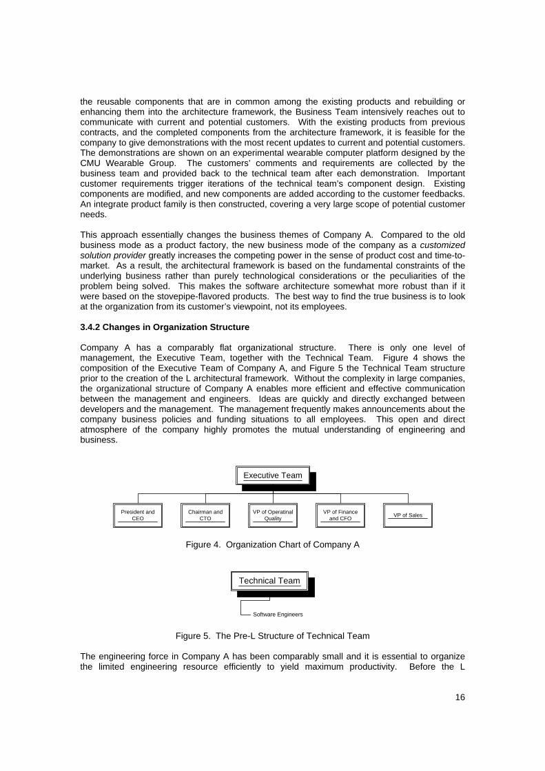
the reusable components that are in common among the existing products and rebuilding or enhancing them into the architecture framework, the Business Team intensively reaches out to communicate with current and potential customers. With the existing products from previous contracts, and the completed components from the architecture framework, it is feasible for the company to give demonstrations with the most recent updates to current and potential customers. The demonstrations are shown on an experimental wearable computer platform designed by the CMU Wearable Group. The customers’ comments and requirements are collected by the business team and provided back to the technical team after each demonstration. Important customer requirements trigger iterations of the technical team’s component design. Existing components are modified, and new components are added according to the customer feedbacks. An integrate product family is then constructed, covering a very large scope of potential customer needs. This approach essentially changes the business themes of Company A. Compared to the old business mode as a product factory, the new business mode of the company as a customized solution provider greatly increases the competing power in the sense of product cost and time-to-market. As a result, the architectural framework is based on the fundamental constraints of the underlying business rather than purely technological considerations or the peculiarities of the problem being solved. This makes the software architecture somewhat more robust than if it were based on the stovepipe-flavored products. The best way to find the true business is to look at the organization from its customer’s viewpoint, not its employees. 3.4.2 Changes in Organization Structure Company A has a comparably flat organizational structure. There is only one level of management, the Executive Team, together with the Technical Team. Figure 4 shows the composition of the Executive Team of Company A, and Figure 5 the Technical Team structure prior to the creation of the L architectural framework. Without the complexity in large companies, the organizational structure of Company A enables more efficient and effective communication between the management and engineers. Ideas are quickly and directly exchanged between developers and the management. The management frequently makes announcements about the company business policies and funding situations to all employees. This open and direct atmosphere of the company highly promotes the mutual understanding of engineering and business.
Executive Team
President andCEO
Chairman andCTO
VP of OperatinalQuality
VP of Financeand CFO VP of Sales
Figure 4. Organization Chart of Company A
Technical Team
Software Engineers
Figure 5. The Pre-L Structure of Technical Team
The engineering force in Company A has been comparably small and it is essential to organize the limited engineering resource efficiently to yield maximum productivity. Before the L
17
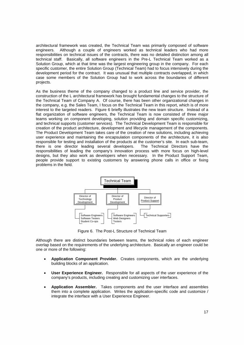
architectural framework was created, the Technical Team was primarily composed of software engineers. Although a couple of engineers worked as technical leaders who had more responsibilities on technical issues of the contracts, there was no detailed distinction among all technical staff. Basically, all software engineers in the Pre-L Technical Team worked as a Solution Group, which at that time was the largest engineering group in the company. For each specific customer, the entire Solution Group (Technical Team) had to focus intensively during the development period for the contract. It was unusual that multiple contracts overlapped, in which case some members of the Solution Group had to work across the boundaries of different projects. As the business theme of the company changed to a product line and service provider, the construction of the L architectural framework has brought fundamental changes to the structure of the Technical Team of Company A. Of course, there has been other organizational changes in the company, e.g. the Sales Team, I focus on the Technical Team in this report, which is of more interest to the targeted readers. Figure 6 briefly illustrates the new team structure. Instead of a flat organization of software engineers, the Technical Team is now consisted of three major teams working on component developing, solution providing and domain specific customizing, and technical supports (customer services). The Technical Development Team is responsible for creation of the product architecture, development and lifecycle management of the components. The Product Development Team takes care of the creation of new solutions, including achieving user experience and maintaining the encapsulation components of the architecture, it is also responsible for testing and installation of the products at the customer’s site. In each sub-team, there is one director leading several developers. The Technical Directors have the responsibilities of leading the company’s innovation process with more focus on high-level designs, but they also work as developers when necessary. In the Product Support Team, people provide support to existing customers by answering phone calls in office or fixing problems in the field.
Technical Team
Director ofTechnology
Development
Director ofProduct
Development
Director ofProduct Support
Software EngineersSoftware TestersStudent Co-ops
Software EngineersWeb DesignersTesters
Technical Supporters
Figure 6. The Post-L Structure of Technical Team
Although there are distinct boundaries between teams, the technical roles of each engineer overlap based on the requirements of the underlying architecture. Basically an engineer could be one or more of the following:
• Application Component Provider. Creates components, which are the underlying building blocks of an application.
• User Experience Engineer. Responsible for all aspects of the user experience of the
company’s products, including creating and customizing user interfaces.
• Application Assembler. Takes components and the user interface and assembles them into a complete application. Writes the application-specific code and customize / integrate the interface with a User Experience Engineer.

18
• Deployer. Configures an application for a particular environment and client. Installs the
application into the on-site server of the clients.
• System Administrator. Responsible for configuring and managing the J2EE server and providing access to deployed applications.
• Tool Provider. Provides an assortment of tools for assisting the various roles.
The introduction of a new architecture framework has brought fundamental changes to the organization, especially to the engineering team. The roles of each developer have changed from a single-dimensional mode, to an overlapped, multi-dimensional mode. As each engineer has increasingly built his knowledge base and therefore taken more responsibilities, the productivity of the Technical Team has basically increased without further strengthening the engineer power. This optimization of team structure, along with the technical strength and engineering practices described in the next sections, contribute to the success of the architecture framework. 3.4.3 Technical Strength of Company The software engineering practice in Company A has benefited from the unique advantage of the strong software engineering background of the company’s management and technical teams. As the natural outgrowth of one of the nation’s best computer science and engineering programs, most members of both the executive and the technical teams in Company A have solid knowledge on software engineering. Among the executive members of the company, there are chaired professors who have highly accomplished academically in the field of computer system technology, human computer interaction, and software engineering. Another two of the company cofounders and current executive members have served respectively as founding director and research project leader at the Software Engineering Institute (SEI) of CMU. Both of them have led many programs that aim at various practical software problems in industry. The technical teams of the company are also composed of outstanding engineers who really understand software engineering. All three technical directors are equipped with profound software engineering expertise gained from numerous years of leadership experience on large-scale software systems, in both industry and academia. One of the most glaring problems with organizations in software industry has been the failure of management to exercise its proper role in the development process. While the new technologies are well understood by the developers, the IT management is often left behind. It is not unusual that the management teams are composed of mainly “professional executive” type of people whose background focuses mainly on business during their education and real world experience. The lack of technical background of the management leads more or less to inadequate insight into the connection between good software engineering practice and the successful future of a project or the whole company. It is not rare that the only targets of the management are to minimize any possible cost, and to maximize the productivity per developer per unit time. They tend to focus more on the schedule, feature and quality of the final product, while thinking of design and process as a waste of time. The management struggles to seek the “silver bullet” technology, while underestimating the effect of slower but more fundamental improvement, even though there are usually some efforts pushed by the technical team to adopt good software engineering practices. As a result, the software engineering practices in many industry organizations are often very primitive. Being equipped with a strong software engineering background, the executive team in Company A understands how good software engineering practice will benefit the company in the long run, and is willing to push this effort from the top level. There leaves enough space for the technical team to carry out good software engineering techniques and adapt to better practices whenever necessary. The communication between the technical and the management teams is usually

19
direct and effective. In particular, the effectiveness of this communication is reflected by the success of innovative evolution of the L architecture, when the technical team feels the need to build a general architecture for future products. It is arguably possible though, that the freedom of research and innovation of the technical team comes partly from the fact that the company has not been facing much external pressure on requirements, costs and schedule. Therefore not much tradeoff has to be made by the executive team between the short-term business goals and the long-term well being of company. 3.4.4 Engineering Processes It is tricky to balance between technology and ceremony in a developing organization. In high ceremony organizations the use of engineering processes becomes bureaucratic that any opportunity for benefit is crushed. In low ceremony organizations, the use of processes becomes so informal that their impact often never reaches beyond the individual developer. In the optimal case, the use of processes is institutionalized, but in a manner that balances the need for control and creativity. The development team at Company A has been following proper processes in their work, during the period I was working with them. A set of customized rules has been established for every engineer to follow. In particular, the routine processes all engineers follow include:
Regular meetings. The overall goals, major milestones for a specific project and detailed schedules for each participant are discussed and set up during the planning phase of a project in this meeting. Each week, engineers should report their progress toward the milestone for all members in the same project to discuss. The milestones are flexible enough to be modified according to changing situations.
Design reviews. Design review and peer discussion are considered to be among the
most effective processes in software development. In Company A, periodical design reviews and peer evaluations are executed rigorously at the end of each design milestone. The engineer who owns the module that is being reviewed provides documentation explaining the design methodologies and implementation details to peer engineers. The design reviews are very effective since most of the problems are found during this process.
Documentation. Documentation are generated and maintained at different development
phases in Company A. During the architecture-building phase, only natural language descriptions along with necessary diagrams explaining the design ideas of the architects are generated. After the top-level architecture has been fully verified and the component design has started, UML is used as the major documentation language. The component design is documented in User Case diagrams, Class diagrams, and Sequence diagrams, which also serve as the major media for peer reviews. In addition, effective design tools that support UML design documentation and automatic code generation, such as Together (TM) from Boland® are intensively used.
The engineering team produces higher quality products, since the process enables engineers to remove defects early, at the source. The regular checkpoints keep the cost and schedule on track, help them to formulate accurate plans and eliminate rework. Although the productivity of individual engineers tends to remain unchanged, the overall productivity increases because of shorter cycle time and less iteration cost. 4. Conclusions

20
This report studies the technology, business, and organizational evolution of a startup software company. Being a spin-off from a university research project, the company has been actively adapting its technical and business schemes toward scaling up and being more competitive in the market. Even under the circumstances of the IT recession, the company has been well situated and has attracted venture capital and customers. In conclusion, I identified that the following engineering practices are essential to the success of a company like Company A:
Adapt business and technical organizations toward real customer needs Strong software engineering background of executives and engineers
Rigorous, institutionalized development processes
Adaptive, flexible and compact organization structure
I try to address as many interesting software engineering issues as possible in this report. As the author has worked with Company A as a part-time student consultant for only four months, the observation and reflection that are given in this report must be limited. 5. Acknowledgement Many thanks to Jim Beck, Dick Martin, Will Ross, and Greg Zelenik, without their help this report could not have been would be no chance for this report to be written. I appreciate all the great suggestions and advice from my advisor, professor Dan Siewiorek. Many thanks to Priya Narasimhan also, who is the second faculty reader of this report.