ex tech sas sl-100 w eat herproof status light/lamp
TRANSCRIPT

PRODUCT NAME: SL-100- WEATHER-PROOF STATUS LIGHT/LA MP
DOC NO.: EX TECH SAS-12-SL100-TM REV03
WEATHERPROOF STATUS LIGHT/LAMP
IP66/67
SL-100 SERIES
EX TECH SAS
SL-100 W EAT HERPROOF STATUS LIGHT/LAMP
TECHNICAL MANUAL
Please note that every care has been taken to ensur e the accuracy of our technical manual. We do not, however,
accept responsibility for damage, loss or expense r esulting from any error or omission. We reserve the right to make
alterations in line with technical advances and ind ustry standards.

EX TECH SAS-12-SL100-TM REV03
1
1.0 INTRODUCTION
SL-100 series Weatherproof Status Light/Lamp is
designed according to EN 54 (BS 5879) standard.
Enclosure material is composite material of PC
(Polycarbonate). It applies to both indoor and outdoor
industrial conditions. Users can choose from multi-
combination types. Xenon and LED Beacons & Lights can
be selected for combination. Junction Box can be fixed.
Three working status-flash, rotary and steady are available
(LED Beacon & Light). Different flash or rotary rate can be
adjusted. Working status type and flash /rotary rate are
preset during installation.
2.0 WEATHER-PROOF LABELING
All products have a rating label, which carries the following
important information:
Product order no.:
e.g. SL100C40RXYXBX05GL05DCNNNB
(Refer to the datasheet for product order selection)
Input voltage: 12-30V DC or 30-60V DC or 100-250V AC
Finish product serial no. (Include date of construction): i.e.
SL1000201080001
SL100- Status Light/Lamp Day-02 Month- 01 Year-08
Product Serial Number- 0001
3.0 TEMPERATURE CLASSIFICATION
The SL100 series products have been certified T4~T6.
This means that the units can be installed in locations with
the following conditions:
Temperature Range: -40 OC <Ta < 70 OC
4.0 INSTALLATION
General Requirement
The product must be installed and maintained according to
EN 54 (BS 5879) standard. Product installation must be
carried out in accordance with any local codes that may
apply and should only be carried out by a competent
electrical engineer.
Location
The location of the unit should be made with due regard to
the area over which the beacon warning signal must be
visible and the manual call point/junction box can be easily
operated. The unit should only be fixed to services that
can carry the weight of the unit.
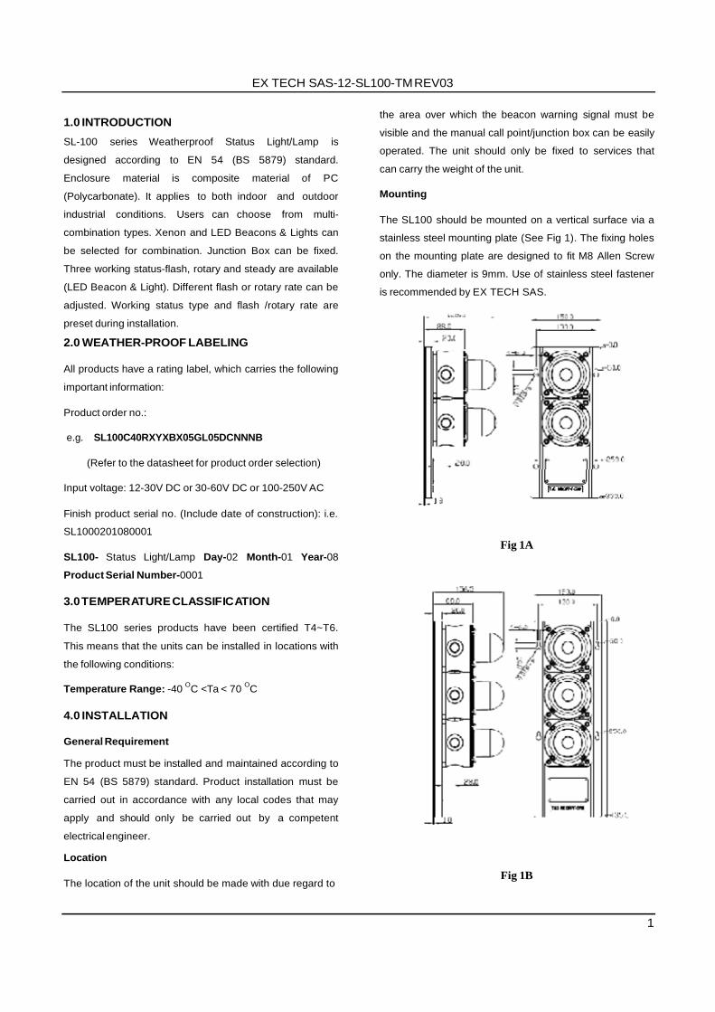
Mounting
The SL100 should be mounted on a vertical surface via a
stainless steel mounting plate (See Fig 1). The fixing holes
on the mounting plate are designed to fit M8 Allen Screw
only. The diameter is 9mm. Use of stainless steel fastener
is recommended by EX TECH SAS.
Fig 1A
Fig 1B
2
EX TECH SAS-12-SL100-TM REV03
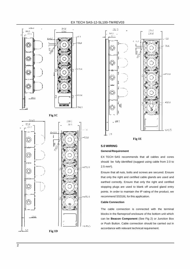
Fig 1C
Fig 1D
Fig 1E
5.0 WIRING
General Requirement
EX TECH SAS recommends that all cables and cores
should be fully identified (suggest using cable from 2.0 to
2.5 mm²).
Ensure that all nuts, bolts and screws are secured. Ensure
that only the right and certified cable glands are used and
earthed correctly. Ensure that only the right and certified
stopping plugs are used to blank off unused gland entry
points. In order to maintain the IP rating of the product, we
recommend SS316L for this application.
Cable Connection
The cable connection is connected with the terminal
blocks in the flameproof enclosure of the bottom unit which
can be Beacon Component (See Fig 2) or Junction Box
or Push Button. Cable connection should be carried out in
accordance with relevant technical requirement.

EX TECH SAS-12-SL100-TM REV03
3
DIP Switch
Fig 2
Remove End Cover (Beacon Component)
Unscrew the four (4) M5 retained hex socket head screws
of the Beacon Component (See Fig 2). This will release
the cover from the base and allow the cover to hang on
the retaining wire strap. Before replacing the cover, check
that the flameproof joints are clean and not damaged, the
gasket is still retained in its groove.
CAUTION: Before removing the cover, ensure the power
to the product is isolated. Remove the four pieces of M5
socket screws to open the cover. Twist the cover gently
clockwise and anti-clockwise, whilst pulling away from the
base, until it comes off. Replace the cover in similar way,
but operate in reverse manner as above.
Supply
12/24V DC or 30-60V DC or 100-240V AC PCB Wiring
Terminals (See Fig 3)
DIP Switch
L N S0S1S2
Xenon PCB
Fig 3
PCB Wiring Terminals (See Fig 3)
Apply power supply to 12V/24V/36V/48V DC 100-250V
‘L’ & ‘N’ (See Fig 3) 7.0 STATUS CHOSEN AND FLASHING FREQUENCY
ADJUSTMENT
LED Beacon
The LED beacon provides flashing and rotary status to be
selected
Use DIP Switch with 3 binary codes on the LED Beacon
PCB to select flashing or rotary status (including steady
status), the 3rd binary code is for high and low frequency
chosen.
LED Status Selection Switch
1st & 2nd DIP Switch: ON=1, OFF=0;
3rd DIP Switch: HIGH= 1, LOW= 0
S1/S2: ON= Connect with 0/COM, OFF= Disconnect with
0/COM
L N S0S1S2
LED PCB

4
EX TECH SAS-12-SL100-TM REV03
DIP Switch
S1/S2 S1=OFF S2=OFF
S1=ON S2=OFF
S1=OFF S2=ON
S1=ON S2=ON
1st
DIP
2nd
DIP
3rd DIP
Alarm
Stage 1
Alarm
Stage 2
Alarm
Stage 3
Alarm
Stage 4
0
0
0(1)
OFF Flash
60 (75) times/min.
Flash 75 (90)
times/min.
Steady
1
0
0(1)
OFF Rotary 60 (75)
times/min
Rotary 75 (90)
times/min
Steady
0
1
0(1)
OFF
Triple Flash
60 (75) times/min.
Triple Flash
75 (90) times/min.
Triple Flash
100(120) times/min.
1
1
0(1)
OFF
Flash
&Rotary 60 (75)
times/min
Flash
&Rotary 75 (90)
times/min
Flash
&Rotary 100(120) times/min
S1/S2 DIP
Switch
S1 = OFF
S2 = OFF
S1 = ON S1 = OFF S1 = ON
S2 = OFF S2 = ON S2 = ON
1
2
Alarm
Stage 1
Alarm Alarm Alarm
Stage 2 Stage 3 Stage 4
1
1
OFF 60 90 120 times/min (1) times/min (1) times/min (1)
0
1
OFF 60 60 60
times/min (2) times/min (3) times/min (4)
1
0
OFF 60 60 60
times/min (3) times/min (4) times/min (5)
0
0
OFF 60 60 60
times/min (4) times/min (5) times/min (6)
heat resisting cable glands must be used, with a rated
service temperature of at least 95ºC.
If a high IP (Ingress Protection) rating is required, a
suitable sealing washer must be fitted under the cable
gland.
When only one cable entry is used, the other one must be
closed with a blanking plug, which must be suitably
approved for the installation requirements.
8.0 END OF LINE MONITORING
Xenon Beacon
The Xenon Beacon provides flashing status Use DIP Switch with 2 binary codes on the Xenon
Beacon PCB (see Fig 3) for frequency adjustment.
Xenon Beacon Flashing Frequency Adjustment DIP Switch: ON=1, OFF=0
S1/S2: ON= Connect to COM, OFF= Disconnect to COM
All the value in () are the number of flash by time
7.0 CABLE GLAND
The SL100 series product has one or two or three cable
gland entries.
SAFETY WARNING : If the SL100 is used at high ambient
temperatures, i.e. over +40ºC, then the cable entry
temperature may exceed +70ºC and therefore suitable
An end of line monitoring diode or an end of line
monitoring resistor can be connected across the 24V+ and
0 terminals. If an end of line monitoring resistor is used, it
must have a maximum resistance value of 3k ohms and a
minimum wattage of 0.5 Watts; or a minimum resistance
value of 1.2k ohms and a maximum wattage of 2 Watts.
9.0 MAINTENANCE
During working life of the product, little or no
maintenance is required due to the robust
maintenance-free surface. Composite material of PC
(Polycarbonate) is abrasion and corrosion resistant
therefore the products are able to use in both indoor
and outdoor industrial condition/ under harsh
environment.
It can also be applied in areas with high impact loads
without additional protective constructions due to
very good mechanical properties.
If abnormal or unusual environmental conditions
occur due to accident etc., visual inspection is
recommended.
To avoid electrostatic charge build-up, only exterior
of the product can be cleaned with a damp cloth.
If spare parts are required, these can be supplied by
EX TECH SAS Company.
If any failure occurs but not caused by human factor,
the product can be returned to EX TECH SAS for
free repair or replacement during warranty period.

EX TECH SAS-12-SL100-TM REV03
5
CAUTION: Not suitable to be used under
circumstance which exposed or near to the source of
concentrated acids, aromatic hydrocarbons,
Halogens and Ketones.
10.1 CONDITIONS FOR SAFETY USE
i. This apparatus is suitable to be used only in
ambient temperature as stated below:
Type Ambient Temp.
SL-100 -40 to +70 ºC
ii. Other than product manufacturer, painting and
surface finishing are not permitted by the third party.
iii. When used in dusty atmosphere, flameproof cable
entry devices or stopping plugs have to be selected
and installed carefully in order to maintain the IP
rating (IP66/67) of the product.
EX TECH SAS. ZE Bandiat Tardoire – 16110 ST PROJET ST CONSTANT
Tel: +33 5 45 61 81 68
Fax: +33 5 45 23 29 46 Website: www.ex-tech.no
E-mail: [email protected]
BEACON D
LN
L-AL-BL-C
L-DNCS0S2
BEACON C/D BEACON B/C BEACON A/B
CT20EXPLOSION
CONNECTION
CT20EXPLOSION
CONNECTION
CT20EXPLOSION
CONNECTION
CT20EXPLOSION
CONNECTION
SW-D
SW-C
SW-B
SW-A
N
L
N
L-A
L-BL-C
L-DNC
S0S2
CN-A
TB-BC TB-BC
N
ONCOM
CABLE
SW-B
SW-D
SW-A
SW-C
Test Switch
L
N
N
L-A
L-BL-C
L-D
NCSW-NSW-L
L-A
L-B
L-C
L-D
Test Power
NC
N
LL
LL
Test Line
TB
-BC
N ON COM
NL-A
L-BL-C
L-D
NC
SW
-NS
W-L
L-A L-B L-C L-D
NC
Test Power
Part NO.:50TB0SAD100 Part NO.:50TBBMAD100
Part N
O.:50TB
BM
AD
100
TO TB-BC TO TB-BC TO TB-BC TO TB-BC TO TB-BC
Wiring For Customer
1 2 3
ON
S1S2S0NL
BEACON PCB1 2 3
ON
S1S2S0NL
BEACON PCB1 2 3
ON
S1S2S0NL
BEACON PCB1 2 3
ON
S1S2S0NL
BEACON PCB1 2 3
ON
S1S2S0NL
BEACON PCB
LN
L-AL-BL-C
L-DNCS0S2
L
N
L-A
L-BL-C
L-DNC
S0S2
CN-A
TB-BC
Part NO.:50TB0SAD100
LN
L-A
L-BL-C
L-DNCS0S2
L
N
L-A
L-BL-C
L-DNC
S0S2
CN-A
TB-BC
Part NO.:50TB0SAD100
LN
L-A
L-BL-C
L-DNCS0S2
L
N
L-A
L-BL-C
L-DNC
S0S2
CN-A
TB-BC
Part NO.:50TB0SAD100
L-A
L-BL-CL-D
TB
-BC
N ON COM
NL-A
L-BL-C
L-D
NC
SW
-NS
W-L
L-A L-B L-C L-D
NC
Part N
O.:50TB
BM
AD
100
Wiring Method for Multiple Unitsof
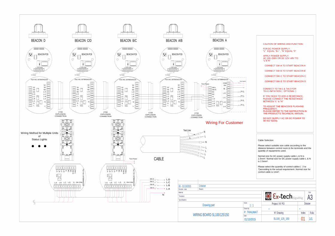
Status Lights Cable Selection
Please select suitable size cable according to thedistance between control room & the terminals and thequantity of equipments used.
Normal size for AC power supply cable L & N is1.5mm². Normal size for DC power supply cable L & Nis 2.5mm².
Please select the quantity of control cables ( 2 to7)according to the actual requirement. Normal size forcontrol cable is 1mm².
CAUTION OF WIRING AND FUNCTION:
FOR DC POWER SUPPLY:"L" EQUAL "B+" , "N" EQUAL "0"
APPLY POWER SUPPLYAC 100~230V OR DC 12V~48V TO"L"&"N"
CONNECT SW-A TO START BEACON A
CONNECT SW-B TO START BEACON B
CONNECT SW-C TO START BEACON C
CONNECT SW-D TO START BEACON D
CONNECT TO Tel-1 & Tel-2 FORTELE-INITIATION ( OPTIONAL )
IF YOU NEED TO ADD A RESISTANCE.PLEASE CONNECT THE RESISTANCEBETWEEN "L" & "N"
TO ADJUST THE BEACON'S FLASHINGFREQUENCY,PLEASE REFER TO THE INSTRUCTION INTHE PRODUCT'S TECHNICAL MANUAL.
DO NOT SUPPLY AC OR DC POWER TOS0 /S1/ S2/Dly.
BEACON A
SL100_125_150 01WIRING BOARD SL100/125/150
- -P. TRAUMAT
01/10/2015
Drawing part 1 : 1
1/1
Specifications
Treatment
Material
Project / N° PO
N° Drawing
Scale :
Drawn by :
Date :
A3Size :
Dossier
FolioIndex
Revision - date00 - 01/10/2015
Reason
Création