excel web ii - honeywell web ii control system – installation & commissioning instructions ......
TRANSCRIPT

® U.S. Registered Trademark
Copyright © 2014 Honeywell Inc. • All Rights Reserved EN1B-0555GE51 R0214
Excel Web II CONTROL SYSTEM
HONEYWELL EXCEL 5000 OPEN SYSTEM INSTALLATION AND COMMISSIONING INSTRUCTIONS
Safety Information 2 General Safety Information 2 Information as per EN 60730 2 WEEE Directive 2 Standards, Approvals, etc. 2
Specifications of Controller 3
System Overview 4 Overview of Models 4 System Architecture 5 Bus and Port Connections 6
Mounting/Dismounting 12 Before Installation 12 Dimensions 12
Wiring and Set-Up 14 General Safety Considerations 14 Wiring Terminals 14 Power Supply 14 Terminal Assignment 15 RIN-APU24 16 Lightning Protection 16 XL2026Bxx Connection Examples 17 Internal I/Os of the Excel Web II 19
Engineering, Commissioning 21 Required Preparations 21
Extra Parts 22
Panel Bus Connection 23 Overview of Panel Bus I/O Modules 23
Panel Bus Considerations 23 Connecting RS485-1 to Panel Buses 24 Connecting RS485-2 to Panel Buses 25 Cable Specifications 26
BACnet MS/TP Bus Connection 27 BACnet MS/TP Bus Considerations 27 Connecting RS485-1 to BACnet MS/TP Buses 27 Connecting RS485-2 to BACnet MS/TP Buses 29
Modbus Connection 30 Modbus Considerations 30 Connecting RS485-1 to the Modbus 30 Connecting RS485-2 to the Modbus 31
M-Bus Connection 32 M-Bus Considerations 32 M-Bus Connection Procedure 33
Troubleshooting 34 Excel Web II Controller Troubleshooting 34 Panel Bus I/O Module Troubleshooting 34
Appendix 1: Earth Grounding 35 Excel Web II Systems and SELV 35 Excel Web II Systems and Standard EN60204-1 35 Earth Grounding of EN60204-1 Applicable Systems 36
Appendix 2 38 Sensor Input Accuracy 38 Recognition of Sensor Failure of Sensor Inputs 38 Sensor Characteristics 38
Index 40
Trademark Information LON, LONWORKS, and Neuron are trademarks of Echelon Corporation registered in the United States and other countries.

EXCEL WEB II CONTROL SYSTEM – INSTALLATION & COMMISSIONING INSTRUCTIONS
EN1B-0555GE51 R0214 2
SAFETY INFORMATION General Safety Information When performing any work, all instructions given by the
manufacturer and in particular the safety instructions provided in these Installation and Commissioning Instructions are to be observed. Make sure that the local standards and regulations are observed at all times.
The Excel Web II System (including the Excel Web II Controller, Honeywell I/O modules, manual disconnect modules, and auxiliary terminal packages) may be installed and mounted only by authorized and trained personnel.
If the controller housing is damaged or missing, immediately disconnect it from any power.
If the device is broken or defective, do not attempt to repair it yourself; rather, return it to the manufacturer.
Always check these Installation Instructions in order to determine which relay terminals are suitable for 230 V. Connect only suitable relay terminals to 230 V.
It is recommended that devices be kept at room tem-perature for at least 24 hours before applying power. This is to allow any condensation resulting from low shipping / storage temperatures to evaporate.
The Excel Web II System must be installed in such a manner (e.g., in a lockable cabinet) as to ensure that uncertified persons have no access to the terminals.
In the case of vertical mounting on DIN rails, the Excel Web II controller should be secured in place using a commercially-available stopper.
If the Excel Web II System is modified in any way, except by the manufacturer, all warranties concerning operation and safety are invalidated.
Rules regarding electrostatic discharge should be followed.
Use only accessory equipment which comes from or has been approved by Honeywell.
Information as per EN 60730 Purpose The Excel Web II Controller is a multifunctional non-safety control device intended for HVAC in home (residential, commercial, and light-industrial) environments.
Construction The Excel Web II Controller is an independently mounted electronic control unit with fixed wiring.
Mounting Method The Excel Web II Controller is suitable for mounting as follows:
in cabinets;
in fuse boxes conforming with standard DIN43880, and having a slot height of max. 45 mm;
in cabinet front doors (using accessory MVC-80-AC2);
on walls (using accessory MVC-80-AC1).
Table 1. Information as per EN 60730
Shock protection Class II
Pollution degree 2
Installation Class 3
Rated impulse voltage 300 V for SELV, 2500 V for relay outputs
Automatic action Type 1.C (micro-interruption for the relay outputs)
Software class Class A
Ball-pressure test temperature
housing parts >75 °C terminals >125 °C
WEEE Directive WEEE: Waste Electrical and Electronic
Equipment Directive
At the end of the product life, dispose of the packaging and product in an appropriate recycling center.
Do not dispose of the device with the usual domestic refuse.
Do not burn the device.
Standards, Approvals, etc. Degree of Protection: IP20 (mounted on walls, with two
accessory MVC-80-AC1 covers) IP30 (mounted in cabinet doors, with
accessory MVC-80-AC2)
Device meets BTL, AMEV AS-A, EN 60730-1, EN 60730-2-9, UL60730, and UL916.
Refer to Code of Practice standards IEC 61000-5-1 and -2 for guidance.
The device complies with Ethernet Protocol versions IEEEC 802.3.
The device supports BACnet IP and BACnet MS/TP communications as per ANSI / ASHRAE 135-2010.
3RD-PARTY SOFTWARE LICENSES This product contains software provided by third parties. See also Excel Web II Controller – Third-Party Software Licenses (Product Literature No.: EN2B-0393GE51).

EXCEL WEB II CONTROL SYSTEM – INSTALLATION & COMMISSIONING INSTRUCTIONS
3 EN1B-0555GE51 R0214
SPECIFICATIONS OF CONTROLLER Table 2. Excel Web II specifications
Power supply 19 … 29 VAC, 50/60 Hz or 20 … 30 VDC
Power consumption
typically dc: 5 W; max. 6 W; with attached XL2000HMI-A: max. 0.5 W higher typically ac: 9 VA; max. 11 VA; with attached XL2000HMI-A: max. 0.5 VA higher
Current consumption typically dc: 210 mA; max. 240 mA typically ac: 370 mA; max. 410 mA
Ambient temperature 0 … 40 °C (wall-mounting) 0 … 50 °C (cabinet/door mounting)
Storage temperature -20 … +70 °C
Humidity 5 … 95% r.h. non-condensing
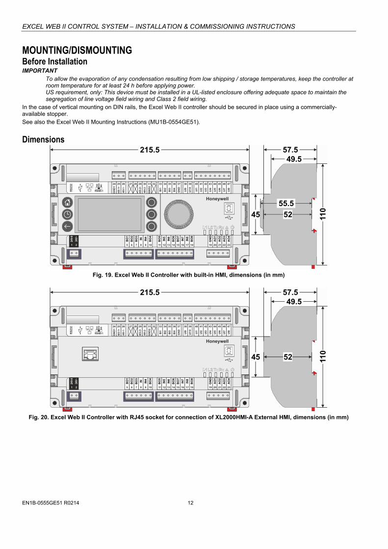
Dimensions See Fig. 19 and Fig. 21.
Degree of protection IP20 (mounted on walls, with two accessory MVC-80-AC1 covers) IP30 (mounted in cabinet doors, with accessory MVC-80-AC2)
Fire class V0
Weight 0.6 kg (excl. packaging)

EXCEL WEB II CONTROL SYSTEM – INSTALLATION & COMMISSIONING INSTRUCTIONS
EN1B-0555GE51 R0214 4
SYSTEM OVERVIEW Overview of Models
Table 3. Overview of models
feature description max. cable length
order no.
XL
2014
B2B
XL
2014
B3B
XL
2026
B2A
XL
2026
B3A
XL
2000
B2A
XL
2000
B3A
UI NTC20kΩ / 0…10V / slow BI 400 m 4 4 8 8 - -
NTC20kΩ / 0…10V fix pull-up / slow BI 400 m - - 2 2 - -
BI open = 24 V / closed 2.0 mA / totalizer 15 Hz 400 m 4 4 4 4 - -
AO 0..11 V (max. 1 mA) 400 m 2 2 4 4 - -
BO
Relay N.O. contact 400 m 3 3 4 4 - -
Relay N.O. contact (high in-rush) 400 m 1 1 1 1 - -
Relay N.O. contact with one common 400 m - - 3 3 - -
bus interfaces
RS485-1, isolated, BACnet MS/TP, Panel Bus, or Modbus RTU Master communication
(1)1200 m 1 1 1 1 1 1
RS485-2, non-isolated, BACnet MS/TP, Panel Bus, or Modbus RTU Master communication
(1)1200 m 1 1 1 1 1 1
Ethernet / RJ45 socket
e-mail communication, browser access 100 m 1 1 1 1 1 1
BACnet IP communication 100 m 1 1 1 1 1 1
USB 2.0 Device Interface (as Network Interface) 3 m 1 1 1 1 1 1
USB 2.0 Host Interface (max. 500 mA) 3 m 1 1 1 1 1 1
RS232 M-Bus communication via PW3 / PW20 / PW60 converters (2)1000 m 1 1 1 1 1 1
user interface
HMI with graphic LCD -- X - X - X -
Fast Access buttons -- 6 - 6 - 6 -
push and turn button -- 1 - 1 - 1 -
HMI
power LED (green) -- 1 1 1 1 1 1
status LED (red, controllable by firmware) -- 1 1 1 1 1 1
applications-specific LED L1 (yellow) -- 1 1 1 1 1 1
USB LED L2 (yellow) -- 1 1 1 1 1 1
bus status LEDs (for isolated RS485-1 interface) -- 2 2 2 2 2 2
HMI socket RJ45 socket for connection of XL2000HMI-A External HMI 5 m -- X -- X -- X (1) Depending upon baud rate. For max. cable lengths, see section "RS485 Standard" on pg. 9. In the case of the Panel Bus, see also section "Panel Bus Considerations" on pg. 23. In the case of the BACnet MS/TP Bus, see also section "BACnet MS/TP Bus Considerations" on pg. 27. In the case of the Modbus, see also section "Modbus Considerations" on pg. 30. (2) Depending upon baud rate. See also section "M-Bus Considerations" on pg. 32.
EXCEL WEB II CONTROL SYSTEM – INSTALLATION & COMMISSIONING INSTRUCTIONS
5 EN1B-0555GE51 R0214
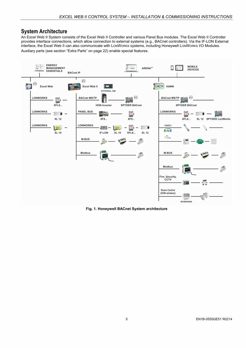
System Architecture An Excel Web II System consists of the Excel Web II Controller and various Panel Bus modules. The Excel Web II Controller provides interface connections, which allow connection to external systems (e.g., BACnet controllers). Via the IF-LON External interface, the Excel Web II can also communicate with LONWORKS systems, including Honeywell LONWORKS I/O Modules. Auxiliary parts (see section “Extra Parts” on page 22) enable special features.
LONWORKS
PANEL BUS
LONWORKS
LONWORKS
Modbus
Modbus
Fire, Security,CCTV
Room Control(HON wireless)
M-BUS
M-BUS
BACnet MS/TP BACnet MS/TP
LONWORKS
LONWORKS
ENERGYMANAGEMENTESSENTIALS
MOBILEDEVICESARENAAX
B LT B LT
BACnet IP
Excel Web HAWK
EXTERNAL HMI
B LT
B LT
Excel Web II
XFL8... HON Inverter SPYDER BACnet SPYDER BACnet
XF8... XF8... XFL8...XL 12 XL 12 SPYDER LonWorks
XFL8...IF-LON XL 12XL 10 XL 10
evohome
Fig. 1. Honeywell BACnet System architecture
EXCEL WEB II CONTROL SYSTEM – INSTALLATION & COMMISSIONING INSTRUCTIONS
EN1B-0555GE51 R0214 6
Bus and Port Connections Overview
WARNING
Risk of electric shock or equipment damage!
Do not touch any live parts in the cabinet! Disconnect the power supply before making connections
to or removing connections from terminals of the Excel Web II Controller or Panel Bus I/O modules.
Do not reconnect the power supply until you have completed installation.
Observe the rules regarding electrostatic discharge.
BI1
BI2
BI3
BI4
GN
D
UI1
UI2
UI3
UI4
UI5
UI6
UI7
24 25 26 27 28 29 30 31 32 33 34 35 36 37 38 39 40 41 42 43 44 45 46
UI8
47
DO
1
DO
2
DO
3
IN IN4
DO
4
DO
5
IN5
IN6
DO
6
DO
7
IN7
IN8
DO
8
GN
D
AO
1
AO
2
AO
3
5 6 7 8 9 10 11 12 13 14 15 16 17 18 19 20 21 22
24V-
0
24V~
1
AO
4
23
6 74 5
GN
D1
485-
1+
485-
1-
GN
D2
485-
2+
485-
2-
UI9
UI1
0
2
1
8
2 3
RS
23
2
RS485-1
END
BIA
SM
ID
Honeywell
Fig. 2. Models with built-in HMI (top view)
BI1
BI2
BI3
BI4
GN
D
UI1
UI2
UI3
UI4
UI5
UI6
UI7
24 25 26 27 28 29 30 31 32 33 34 35 36 37 38 39 40 41 42 43 44 45 46
UI8
47
DO
1
DO
2
DO
3
IN IN4
DO
4
DO
5
IN5
IN6
DO
6
DO
7
IN7
IN8
DO
8
GN
D
AO
1
AO
2
AO
3
5 6 7 8 9 10 11 12 13 14 15 16 17 18 19 20 21 22
24V-
0
24V~
1
AO
4
23
6 74 5
GN
D1
485-
1+
485-
1-
GN
D2
485-
2+
485-
2-
UI9
UI1
0
2
9
J1 J8
1
8
2 3
RS
23
2
RS485-1
END
BIA
SM
ID
Honeywell
Fig. 3. Models without built-in HMI (top view)
1 8
3
J1 J8
END
BIA
SM
ID
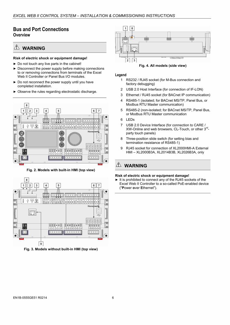
2 Fig. 4. All models (side view)
Legend 1 RS232 / RJ45 socket (for M-Bus connection and
factory debugging)
2 USB 2.0 Host Interface (for connection of IF-LON)
3 Ethernet / RJ45 socket (for BACnet IP communication)
4 RS485-1 (isolated; for BACnet MS/TP, Panel Bus, or Modbus RTU Master communication)
5 RS485-2 (non-isolated; for BACnet MS/TP, Panel Bus, or Modbus RTU Master communication
6 LEDs
7 USB 2.0 Device Interface (for connection to CARE / XW-Online and web browsers, CL-Touch, or other 3rd-party touch panels)
8 Three-position slide switch (for setting bias and termination resistance of RS485-1)
9 RJ45 socket for connection of XL2000HMI-A External HMI – XL2000B3A, XL2014B3B, XL2026B3A, only
WARNING
Risk of electric shock or equipment damage! It is prohibited to connect any of the RJ45 sockets of the
Excel Web II Controller to a so-called PoE-enabled device ("Power over Ethernet").

EXCEL WEB II CONTROL SYSTEM – INSTALLATION & COMMISSIONING INSTRUCTIONS
7 EN1B-0555GE51 R0214
RS232 / RJ45 Socket Via its RS232 / RJ45 socket, the Excel Web II Controller can be connected (using an XW586 cable) to a PW M-Bus Adapter and thus to M-Bus networks. See also section "M-Bus Connection" on pg. 32.
RS232-RJ45 SOCKET
J1J8
END
BIA
SM
ID
Fig. 5. RS232 / RJ45 socket
USB 2.0 Host Interface Via its USB 2.0 Host interface, the Excel Web II Controller can be connected to, e.g., the IF-LON External Interface Adapter and thus to LONWORKS networks. Max. 500 mA, high speed.
USB 2.0 Host Interface
J1J8
END
BIA
SM
ID
Fig. 6. USB 2.0 Host interface
LonWorks Connection The IF-LON is equipped with a free-topology transceiver (FTT10A) for communication (at a data transmission rate of 78 Kbaud) on LONWORKS® networks (using the LonTalk protocol). The LONWORKS network is insensitive to polarity, eliminating the possibility of installation errors due to miswiring. Different network configurations (daisy-chain, loop, and star con-figurations, or any combination thereof) are possible. See Excel 50/5000 LONWORKS Mechanisms (EN0B-0270GE51) for details.
IF-LON
Fig. 7. IF-LON
See also IF-LON – Mounting Instructions (MU1B-0545GE51).
USB 2.0 Device Interface All models of the Excel Web II Controller are equipped with a USB 2.0 Device Interface at the front. This interface is for connection to CARE / XW-Online and web browsers, CL-Touch, or other 3rd-party touch panels.
BI1
BI2
BI3
BI4
GN
D
UI1
UI2
UI3
UI4
UI5
UI6
UI7
32 33 34 35 36 37 38 39 40 41 42 43 44 45 46
UI8
47
n.a
.
UI9
UI1
0
USB 2.0 Device Interface
Honeywell
Fig. 8. USB 2.0 Device Interface
A standard USB type-B connector can be inserted into this USB 2.0 Device Interface. This USB 2.0 Device Interface is the recommended interface for connection to CARE.
Ethernet / RJ45 Socket All models of the Excel Web II Controller are equipped with an Ethernet / RJ45 socket featuring one LED.
J1J8
Ethernet / RJ45 socket
END
BI A
SM
ID
Fig. 9. Ethernet / RJ45 socket
This Ethernet / RJ45 socket is a 10/100-Mbaud Ethernet interface permitting communication (as per IEEEC 802.3) on BACnet IP networks.
EXCEL WEB II CONTROL SYSTEM – INSTALLATION & COMMISSIONING INSTRUCTIONS
EN1B-0555GE51 R0214 8
LINK/ACT.
Fig. 10. Ethernet / RJ45 socket
NOTE: The Ethernet / RJ45 socket is usually earth-grounded. For additional information on earth grounding, see also “Appendix 1: Earth Grounding” on pg. 35.
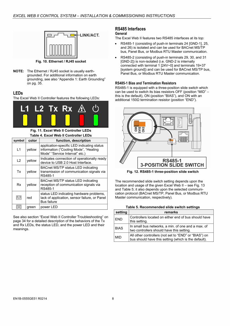
LEDs The Excel Web II Controller features the following LEDs:
Fig. 11. Excel Web II Controller LEDs
Table 4. Excel Web II Controller LEDs
symbol color function, description
L1 yellow application-specific LED indicating status information (“Cooling Mode”, “Heating Mode” “Service Interval” etc.)
L2 yellow Indicates connection of operationally ready device to USB 2.0 Host Interface.
Tx yellow BACnet MS/TP status LED indicating transmission of communication signals via RS485-1
Rx yellow BACnet MS/TP status LED indicating reception of communication signals via RS485-1
! red status LED indicating hardware problems, lack of application, sensor failure, or Panel Bus failure
green power LED
See also section “Excel Web II Controller Troubleshooting” on page 34 for a detailed description of the behaviors of the Tx and Rx LEDs, the status LED, and the power LED and their meanings.
RS485 Interfaces General The Excel Web II features two RS485 interfaces at its top:
RS485-1 (consisting of push-in terminals 24 [GND-1], 25, and 26) is isolated and can be used for BACnet MS/TP bus, Panel Bus, or Modbus RTU Master communication.
RS485-2 (consisting of push-in terminals 29, 30, and 31 [GND-2]) is non-isolated (i.e. GND-2 is internally connected with terminal 1 [24V~0] and terminals 19+37 [system ground]) and can be used for BACnet MS/TP bus, Panel Bus, or Modbus RTU Master communication.
RS485-1 Bias and Termination Resistors RS485-1 is equipped with a three-position slide switch which can be used to switch its bias resistors OFF (position “MID” – this is the default), ON (position “BIAS”), and ON with an additional 150Ω termination resistor (position “END”).
J1J8
RS485-13-POSITION SLIDE SWITCH
END
BI A
SM
ID
END
BIA
SM
ID
Fig. 12. RS485-1 three-position slide switch
The recommended slide switch setting depends upon the location and usage of the given Excel Web II – see Fig. 13 and Table 5; it also depends upon the selected communi-cation protocol (BACnet MS/TP, Panel Bus, or Modbus RTU Master communication, respectively).
Table 5. Recommended slide switch settings
setting remarks
END Controllers located on either end of bus should have this setting.
BIAS In small bus networks, a min. of one and a max. of two controllers should have this setting.
MID All other controllers (not set to “END” or “BIAS”) on bus should have this setting (which is the default).

EXCEL WEB II CONTROL SYSTEM – INSTALLATION & COMMISSIONING INSTRUCTIONS
9 EN1B-0555GE51 R0214
47 kOHM
47 kOHM
+5VISO
GND-1
RS485-1 (+)
RS485-1 (-)
25
26
MID (DEFAULT)
END
BIA
SM
ID
Fig. 13. RS485-1 three-position slide switch setting MID
550 OHM
550 OHM
+5VISO
GND-1
RS485-1 (+)
RS485-1 (-)
25
26
BIAS
END
BIA
SM
ID
Fig. 14. RS485-1 three-position slide switch setting BIAS
550 OHM
150 OHM
550 OHM
+5VISO
GND-1
RS485-1 (+)
RS485-1 (-)
25
26
END
END
BIA
SM
ID
Fig. 15. RS485-1 three-position slide switch setting END
NOTE: All terminals are protected (up to 24 Vac) against short-circuiting and incorrect wiring – except when the 3-position slide switch is set to “END,” in which case the terminals of the RS485-1 bus (24, 25, and 26) have no such protection. Higher voltages may damage the device.
NOTE: According to BACnet standards, a minimum of one and a maximum of two BACnet devices must have its/their bias resistors switched ON. In the case of the RS485-1 interface of the Excel Web II, setting its slide switch to either "BIAS" or "END" fulfills this requirement.
RS485-2 Bias and Termination Resistors The RS485-2 interface is not affected by the aforementioned three-position slide switch. The 550Ω bias resistors and 130Ω termination resistor of the RS485-2 are thus always ON.
550 OHM
130 OHM
550 OHM
+5V
GND-2
RS485-2 (+)
RS485-2 (-)
30
31
Fig. 16. RS485-2 bias and termination resistors
NOTE: GND-2 is internally connected with 24V-0 (terminal 1) and system GND (terminals 19+37)
RS485 Standard According to the RS485 standard (TIA/EIA-485: “Electrical Characteristics of Generators and Receivers for Use in Balanced Digital Multipoint Systems”), only one driver com-municating via an RS485 interface may transmit data at a time. Further, according to U.L. requirements, each RS485 interface may be loaded with a max. of 32 unit loads. E.g., Honeywell devices have as little as ¼ unit load each, so that up to 128 devices can be connected. BACnet MS/TP connections to the RS485 interfaces must comply with the aforementioned RS485 standard. Thus, it is recommended that each end of every connection be equipped with one termination resistor having a resistance equal to the cable impedance (120 Ω / 0.25 – 0.5 W). RS485 systems frequently lack a separate signal ground wire. However, the laws of physics still require that a solid ground connection be provided for in order to ensure error-free communication between drivers and receivers – unless all of the devices are electrically isolated and no earth grounding exists.
IMPORTANT In the case of new Excel Web II controller installations, we strongly recommend using a separate signal ground wire. Doing otherwise may possibly lead to unpredictable behavior if other electrically non-isolated devices are connected and the potential difference is too high. In the case of the installation of Excel Web II controllers in already-existent RS485 two-wire systems (e.g., when replacing Excel 800 or CPO-PC-6A controllers with Excel Web II controllers), not using a separate signal ground wire will probably have no undesirable effects.
The cable length affects the baud rate. The following table provides a few examples.

EXCEL WEB II CONTROL SYSTEM – INSTALLATION & COMMISSIONING INSTRUCTIONS
EN1B-0555GE51 R0214 10
Table 6. Baud rate vs. max. cable length for RS485
Baud rate Max. cable length (L)
9.6 - 76.8 kbps 1200 m
*115.2 kbps 800 m
** In the case of configuration of RS485-2 for Panel Bus, the communication rate is set to 115.2 kbps.
For information on wire gauge, max. permissible cable length, possible shielding and grounding requirements, and the max. number of devices which can be connected to a bus, refer to standard EIA-485. Modbus Connection The Excel Web II controller can function as a Modbus Master. In general, the RS485 wiring rules must be followed. Wiring Topology Only daisy-chain wiring topology is allowed. Short derivation ("stub") cables (with a max. length of 20 m) from the "trunk cable" to the Modbus devices are allowed.
MODBUSMASTER
MODBUSSLAVE
MODBUSSLAVE
MODBUSSLAVE
MODBUSSLAVE
Fig. 17. Allowed Modbus wiring topology
Other wiring topologies (e.g., star wiring, or mixed star wiring and daisy chain wiring) are prohibited; this is to avoid communication problems of the physical layer.
MODBUSMASTER
MODBUSSLAVE
MODBUSSLAVE
MODBUSSLAVE
MODBUSSLAVE
MODBUSSLAVE
MODBUSSLAVE
Fig. 18. Prohibited Modbus wiring topology (example)
Cables See also section "EIA 485 Cable Specifications" on pg. 26. Use shielded twisted pair cable J-Y-(St)-Y 2 x 2 x 0,8.
You must use three wires:
One wire for D1 = Modbus +
One wire for D0 = Modbus –
One wire for the signal common
When using one pair for D1 and D0 and one wire of another pair for the signal common, CAT5 cable may also be used. For connection details, see section "Modbus Connection" on pg. 30. Shielding Shielding is especially recommended when the Modbus cable is installed in areas with expected or actual electromagnetic noise. Avoiding such areas is to be preferred. Use shielded twisted pair cable shielded twisted pair cable J-Y-(St)-Y 2 x 2 x 0,8 and connect the Modbus to a noise-free earth ground – only once per Modbus connection. RS485 Repeaters RS485 repeaters are possible, but have not been tested by Honeywell. Hence it is within responsibility of the installing/commissioning person to ensure proper function.
NOTE: Each Modbus segment will require its own line polarization and line termination.
Modbus Master Specifications Modbus Compliance As per the Modbus standard, the Excel Web II controller is a conditionally compliant "regular" Modbus device. The Excel Web II controller differs from an unconditionally compliant "regular" Modbus device in that it does not support communication rates of 1.2, 2.4, and 4.8 kBaud (because these communication rates are not market-relevant). Physical Layer 2-wire serial line RS485 (EIA-485) (with additional common) Communication rates: 9.6, 19.2, 38.4, 57.6, 76.8, and
115.2 kBaud supported. Max. number of devices: 32 Cable and wiring specifications: See section "Wiring and Set-Up" on pg. 14. Communication Mode Modbus Master. Transmission Mode RTU (Remote Terminal Unit) Address Range Modbus slaves can have an address between 1 and 247. Discrete Inputs, Coils, Input Registers and Holding Registers can have an address between 1 and 9999. Function Codes The following function codes are supported:
Table 7. Supported function codes function code (hex) function
02 Read Discrete Inputs 01 Read Coils 05 Write Single Coil 04 Read Input Register 03 Read Holding Register 06 Write Single Register 10 Write Multiple Registers
EXCEL WEB II CONTROL SYSTEM – INSTALLATION & COMMISSIONING INSTRUCTIONS
11 EN1B-0555GE51 R0214
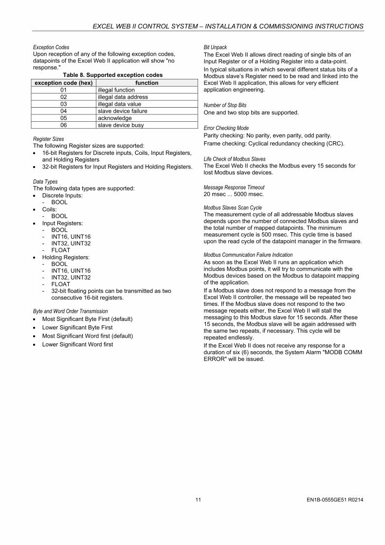
Exception Codes Upon reception of any of the following exception codes, datapoints of the Excel Web II application will show "no response."
Table 8. Supported exception codes exception code (hex) function
01 illegal function 02 illegal data address 03 illegal data value 04 slave device failure 05 acknowledge 06 slave device busy
Register Sizes The following Register sizes are supported: 16-bit Registers for Discrete inputs, Coils, Input Registers,
and Holding Registers 32-bit Registers for Input Registers and Holding Registers. Data Types The following data types are supported: Discrete Inputs:
- BOOL Coils:
- BOOL Input Registers:
- BOOL - INT16, UINT16 - INT32, UINT32 - FLOAT
Holding Registers: - BOOL - INT16, UINT16 - INT32, UINT32 - FLOAT - 32-bit floating points can be transmitted as two
consecutive 16-bit registers. Byte and Word Order Transmission Most Significant Byte First (default)
Lower Significant Byte First
Most Significant Word first (default)
Lower Significant Word first
Bit Unpack The Excel Web II allows direct reading of single bits of an Input Register or of a Holding Register into a data-point. In typical situations in which several different status bits of a Modbus slave’s Register need to be read and linked into the Excel Web II application, this allows for very efficient application engineering. Number of Stop Bits One and two stop bits are supported. Error Checking Mode Parity checking: No parity, even parity, odd parity. Frame checking: Cyclical redundancy checking (CRC). Life Check of Modbus Slaves The Excel Web II checks the Modbus every 15 seconds for lost Modbus slave devices. Message Response Timeout 20 msec ... 5000 msec. Modbus Slaves Scan Cycle The measurement cycle of all addressable Modbus slaves depends upon the number of connected Modbus slaves and the total number of mapped datapoints. The minimum measurement cycle is 500 msec. This cycle time is based upon the read cycle of the datapoint manager in the firmware. Modbus Communication Failure Indication As soon as the Excel Web II runs an application which includes Modbus points, it will try to communicate with the Modbus devices based on the Modbus to datapoint mapping of the application. If a Modbus slave does not respond to a message from the Excel Web II controller, the message will be repeated two times. If the Modbus slave does not respond to the two message repeats either, the Excel Web II will stall the messaging to this Modbus slave for 15 seconds. After these 15 seconds, the Modbus slave will be again addressed with the same two repeats, if necessary. This cycle will be repeated endlessly. If the Excel Web II does not receive any response for a duration of six (6) seconds, the System Alarm "MODB COMM ERROR" will be issued.
EXCEL WEB II CONTROL SYSTEM – INSTALLATION & COMMISSIONING INSTRUCTIONS
EN1B-0555GE51 R0214 12
MOUNTING/DISMOUNTING Before Installation IMPORTANT
To allow the evaporation of any condensation resulting from low shipping / storage temperatures, keep the controller at room temperature for at least 24 h before applying power. US requirement, only: This device must be installed in a UL-listed enclosure offering adequate space to maintain the segregation of line voltage field wiring and Class 2 field wiring.
In the case of vertical mounting on DIN rails, the Excel Web II controller should be secured in place using a commercially-available stopper. See also the Excel Web II Mounting Instructions (MU1B-0554GE51).
Dimensions
110
215.5
45
BI1
BI2
BI3
BI4
GN
D
UI1
UI2
UI3
UI4
UI5
UI6
UI7
24 25 26 27 28 29 30 31 32 33 34 35 36 37 38 39 40 41 42 43 44 45 46
UI8
47
BO
1
BO
2
BO
3
IN IN4
BO
4
BO
5
IN5
IN6
BO
6
BO
7
IN7
IN8
BO
8
GN
D
AO
1
AO
2
AO
3
5 6 7 8 9 10 11 12 13 14 15 16 17 18 19 20 21 22
24V-
0
24V~
1
AO
4
23
GN
D1
485-
1+
485-
1-
GN
D2
485-
2+
485-
2-
UI9
UI1
0
2
52
49.557.5
55.5
RS
232
RS485-1
END
BIA
SM
ID
Honeywell
Fig. 19. Excel Web II Controller with built-in HMI, dimensions (in mm)
110
215.5
5245
BI1
BI2
BI3
BI4
GN
D
UI1
UI2
UI3
UI4
UI5
UI6
UI7
24 25 26 27 28 29 30 31 32 33 34 35 36 37 38 39 40 41 42 43 44 45 46
UI8
47
BO
1
BO
2
BO
3
IN IN4
BO
4
BO
5
IN5
IN6
BO
6
BO
7
IN7
IN8
BO
8
GN
D
AO
1
AO
2
AO
3
5 6 7 8 9 10 11 12 13 14 15 16 17 18 19 20 21 22
24V-
0
24V~
1
AO
4
23
GN
D1
485-
1+
485-
1-
GN
D2
485-
2+
485-
2-
UI9
UI1
0
2
49.557.5
J1 J8
RS
232
RS485-1
END
BIA
SM
ID
Honeywell
Fig. 20. Excel Web II Controller with RJ45 socket for connection of XL2000HMI-A External HMI, dimensions (in mm)
EXCEL WEB II CONTROL SYSTEM – INSTALLATION & COMMISSIONING INSTRUCTIONS
13 EN1B-0555GE51 R0214
147
57.5215.5
52
55.5
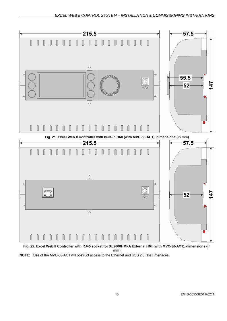
Fig. 21. Excel Web II Controller with built-in HMI (with MVC-80-AC1), dimensions (in mm)
147
57.5215.5
J1 J8
52
Fig. 22. Excel Web II Controller with RJ45 socket for XL2000HMI-A External HMI (with MVC-80-AC1), dimensions (in
mm)
NOTE: Use of the MVC-80-AC1 will obstruct access to the Ethernet and USB 2.0 Host Interfaces

EXCEL WEB II CONTROL SYSTEM – INSTALLATION & COMMISSIONING INSTRUCTIONS
EN1B-0555GE51 R0214 14
WIRING AND SET-UP General Safety Considerations All wiring must comply with applicable electrical codes and
ordinances, including VDE, National Electric Code (NEC) or equivalent, and any local regulations must be observed. Refer to job or manufacturer’s drawings for details. Local wiring guidelines (e.g., IEC 364-6-61 or VDE 0100) may take precedence over recommendations provided here.
Electrical work should be carried out by a qualified electrician.
Electrical connections must be made at terminal blocks.
For Europe only: To comply with CE requirements, devices with a voltage in the range of 50 ... 1000 VAC or 75 ... 1500 VDC which are not provided with a supply cord and plug or with other means for disconnection from the supply having a contact separation of at least 3 mm in all poles must have the means for disconnection incorporated in the fixed wiring.
WARNING
Risk of electric shock or equipment damage! Observe precautions for handling electrostatic sensitive
devices. Do not touch any live parts in the cabinet. Do not open the controller housing. Disconnect the power supply before making connections to
or removing connections from terminals of the Excel Web IIController and devices wired to it.
Do not use spare terminals as wiring support points. Mixing of different voltages (e.g., 24 V and 230 V) within
individual relay blocks of the Excel Web II is not allowed To prevent risk of injury due to electrical shock and/or
damage to the device due to short-circuiting, low-voltage and high-voltage lines must be kept separate from one another.
All terminals are protected (up to 24 Vac) against short-circuiting and incorrect wiring (unless the 3-position slide switch is set to “END,” in which case the terminals of the RS485-1 bus [24, 25, and 26] have no such protection). Higher voltages may damage the device.
Do not reconnect the power supply until you have completed the installation.
Fusing Specifications System Fusing We recommend that the user equip the system with an external fuse. Fusing of Active Field Devices F2 (depends upon loads in use).
Wiring Terminals The Excel Web II is equipped with push-in terminal plugs.
Fig. 23. Inserting/removing wires from push-in terminals
NOTE: With solid conductors, ferrules are prohibited.
NOTE: Use only one conductor per push-in terminal.
NOTE: If, nevertheless, two stranded wires are to be connected to a single push-in terminal, twin wire end ferrules must be used.
Table 9. Excel Web II push-in terminal wiring specifications
plug gauge 0.2 … 1.50 mm2
solid conductor H05(07) V-K 0.2 … 1.50 mm2
stranded conductor H05(07) V-K 0.2 … 1.50 mm2
stranded conductor with wire end ferrules (w/o plastic collar)
0.2 … 1.50 mm2
stripping length 10.0 +1.0 mm
Power Supply Powering Excel Web II Power is supplied via a removable terminal plug (attached to terminals 1 and 2). See also Fig. 26. The power supply of the Excel Web II Controller must conform to Safety Class II. To reduce overall current consumption, the Excel Web II can be powered by a switch power supply (rather than by a transformer). See also Table 2 on pg. 3.
NOTE: Danger of short-circuiting when another controller besides the Excel Web II Controller is supplied by the same transformer if proper polarity is not ensured. See Fig. 24.
24 V~
24 V~0
LINEL
N
CPU 1 CPU 2
NOISE-FREE EARTH GROUND(ONLY ONE PER SYSTEM)
N, L
EARTH GROUND
USB 2.0Device Interface
! REVERSEDPOLARITY!
SHORT-CIRCUITING!
PC 1 PC 2
2 21 1
24V~ 24V~24V~0 24V~0
Fig. 24. Incorrect polarity → SHORT-CIRCUITING!

EXCEL WEB II CONTROL SYSTEM – INSTALLATION & COMMISSIONING INSTRUCTIONS
15 EN1B-0555GE51 R0214
Terminal Assignment Table 10. Terminal assignment
term
inal
no
.
signal Description
XL
2014
BxB
XL
2026
Bxx
XL
2000
Bxx
1 24V-0 supply voltage (GND), internally connected with term. 31 and system GND (term. 19+37) X X X 2 24V~ supply voltage (24V) X X X
3,4 - not used - - -
5 BO1 Binary output 1. N.O. relay contact switching input power connected to terminal 8 - X - 6 BO2 Binary output 2. N.O. relay contact switching input power connected to terminal 8 - X - 7 BO3 Binary output 3. N.O. relay contact switching input power connected to terminal 8 - X - 8 IN1,2,3 Common relay contact for BO1, BO2, and BO3 - X - 9 IN4 Common relay contact for BO4 X X - 10 BO4 Binary output 4. N.O. relay contact switching input power connected to terminal 9 X X - 11 BO5 Binary output 5. N.O. relay contact switching input power connected to terminal 12 X X - 12 IN5 Common relay contact for BO5 X X - 13 IN6 Common relay contact for BO6 X X - 14 BO6 Binary output 6. N.O. relay contact switching input power connected to terminal 13 X X - 15 BO7 Binary output 7. N.O. relay contact switching input power connected to terminal 16 X X - 16 IN7 Common relay contact for BO7 X X - 17 IN8 Common relay contact for BO8 - X - 18 BO8 Binary output 8. N.O. relay contact switching input power connected to terminal 17 - X -
19 GND Ground terminal (see NOTE below) X X -
20 AO1 Analog output 1 X X - 21 AO2 Analog output 2 X X - 22 AO3 Analog output 3 - X - 23 AO4 Analog output 4 - X -
24 GND-1 ref. GND of RS485-1 (isolated) X X X 25 485-1+ “+” signal for RS485-1 (isolated) X X X 26 485-1- “-” signal for RS485-1 (isolated) X X X
27,28 not used - - -
29 485-2+ “+” signal for RS485-2 (non-isolated) X X X 30 485-2- “-” signal for RS485-2 (non-isolated) X X X 31 GND-2 ref. GND of RS485-2, int. connected with 24V-0 (term. 1) and system GND (term. 19+37) X X X
32 - not used - - -
33 BI1 Binary input 1 (static dry contact) / pulse counter (fast totalizer) X X - 34 BI2 Binary input 2 (static dry contact) / pulse counter (fast totalizer) X X - 35 BI3 Binary input 3 (static dry contact) / pulse counter (fast totalizer) X X - 36 BI4 Binary input 4 (static dry contact) / pulse counter (fast totalizer) X X -
37 GND Ground terminal (see NOTE below) X X -
38 UI9 Universal input 9 (for NTC20kΩ / 0..10V / slow BI) - X - 39 UI10 Universal input 10 (for NTC20kΩ / 0..10V / slow BI) - X - 40 UI1 Universal input 1 (for NTC20kΩ / 0..10V / slow BI) X X - 41 UI2 Universal input 2 (for NTC20kΩ / 0..10V / slow BI) X X - 42 UI3 Universal input 3 (for NTC20kΩ / 0..10V / slow BI) X X - 43 UI4 Universal input 4 (for NTC20kΩ / 0..10V / slow BI) X X - 44 UI5 Universal input 5 (for NTC20kΩ / 0..10V / slow BI) - X - 45 UI6 Universal input 6 (for NTC20kΩ / 0..10V / slow BI) - X - 46 UI7 Universal input 7 (for NTC20kΩ / 0..10V / slow BI) - X - 47 UI8 Universal input 8 (for NTC20kΩ / 0..10V / slow BI) - X -
NOTE: All AOs, UIs, and BIs share the same ground potential. It is thus possible to connect just one combined GND signal for all AOs, UIs, and BIs. Auxiliary terminals may be used if needed.

EXCEL WEB II CONTROL SYSTEM – INSTALLATION & COMMISSIONING INSTRUCTIONS
EN1B-0555GE51 R0214 16
Transformer Data In Europe, if the Excel Web II is powered by transformers, then such transformers must be safety isolating transformers conforming to IEC61558-2-6. In the U.S. and Canada, if the Excel Web II is powered by transformers, then such transformers must be NEC Class-2 transformers.
Table 11. 1450 series transformers data part #
1450 7287 primary side secondary side
-001 120 Vac 24 Vac, 50 VA
-002 120 Vac 2 x 24 Vac, 40 VA, and 100 VA from separate transformer
-003 120 Vac 24 Vac, 100 VA, and 24 Vdc, 600 mA
-004 240/220 Vac 24 Vac, 50 VA
-005 240/220 Vac 2 x 24 Vac, 40 VA, and 100 VA from separate transformer
-006 240/220 Vac 24 Vac, 100 VA, and 24 Vdc, 600 mA
Table 12. Overview of CRT Series AC/DC current
transformer primary side
max. AC current
max. DC current
CRT 2 230 Vac 2 A 500 mA
CRT 6 230 Vac 6 A 1300 mA
CRT 12 230 Vac 12 A 2500 mA
NOTRECOMMENDED
PRIMARYSIDE Excel Web II
1
224 V~230 Vac120 Vac 24 V0
Fig. 25. Connection of Excel Web II Controller
RIN-APU24 The RIN-APU24 Uninterruptable Power Supply can be directly wired to an Excel Web II Controller. See RIN-APU24 Uninterruptable Power Supply – Mounting Instructions (EN0B-0382GE51) for a detailed wiring diagram.
Powering Panel Bus I/O Modules and Field Devices The Excel Web II, Panel Bus I/O modules, and field devices can be powered by either separate transformers (see Fig. 26, Fig. 27, and Fig. 28) or by the same transformer (see Fig. 29 on pg. 17).
NOTE: Use a min. distance of 10 cm between power cables and 0…10 V / sensor cables in order to prevent signal disturbances on the 0…10 V / sensor cables. See also section “Cable Specifications” on page 26.
Powering Field Devices and Excel Web II via Separate Transformers 24 V actuator connected to separate transformer
Field device located max. 400 m from Excel Web II
Y (0...10 Vdc)
24 V0
24 V~
230 V~
230 V~
24 V~
24 V0
GND
Y
24V~
F2
1
2
20...23
19
max. 400 m
Excel Web II
Fig. 26. Power supply of Excel Web II and field devices by
separate transformer Powering Field Devices and Panel Bus I/O Module via Separate Transformers 24 V actuator connected to, e.g., an analog output module
Field device located 100 … 400 m from Excel Web II
24 V0230 V~
24 V~
max. 400 m
XF822
73
74 1...8
GND
Y
24V~
11...18
F1
24 V0230 V~
24 V~
F2
Y (0...10 Vdc)
Fig. 27. Power supply via a separate transformer
Powering Field Devices via Panel Bus I/O Module 24 V actuator connected to, e.g., an analog output module
Field device located max. 100 m from Excel Web II
Y (0...10 Vdc)24 V0
230 V~24 V~
max. 100 m
73
74 1...8
GND
Y
24V~
11...18
F1
F2
XF822
Fig. 28. Power supply via Panel Bus I/O Module
Lightning Protection Please contact your local Honeywell representative for information on lightning protection.

EXCEL WEB II CONTROL SYSTEM – INSTALLATION & COMMISSIONING INSTRUCTIONS
17 EN1B-0555GE51 R0214
XL2026Bxx Connection Examples
FAN~~
1: 24V 02: 24V
FAN~~
1: 24V 02: 24V
TOTALIZER1: GND2: SIGNAL
21
FAN1: GND2: 24V~
FAN1: 230V N2: 230V~
M M
1 12 2
XL2026Bxx
BO
1
BO
2
BO
3
IN IN4
BO
4
BO
5
IN5
IN6
BO
6
BO
7
IN7
IN8
BO
8
5 6 7 8 9 10 11 12 13 14 15 16 17 18
AO
3
22
AO
2
21
AO
1
20G
ND
19
~
AO
4
23
GN
D1
GN
D2
485-
1+
485-
2+
485-
1-
485-
2-
n.a
.
n.a
.
n.a
.
BI1
BI2
BI3
BI4
UI1
UI9
UI1
0
UI2
UI3
UI4
UI5
UI6
UI7
24 25 26 27 28 29 30 31 32 33 34 35 36 38 39 40 41 42 43 44 45 46
UI8
47
GN
D
37
DRYCONTACT1: GND2: SIGNAL
21
37/GN
D
37/GN
D
37/GN
D
37/GN
D
1
1
2
2
24V
1: GND (24V 0)2: 24V POWER3: 0...10 VDC
~ DRIVE with0...10V SIGNAL
~~
2 31
M 0...10 VDC
NTC20kOHMSENSOR1: GND2: SIGNAL
1 2
NTC20kOHMSENSOR1: GND2: SIGNAL
1 2
24Vac
ACTIVE SENSOR1: GND (24V 0)2: 24V POWER3: 0...10 VDC
~~
2 3124
V-0
24V~
1 2
LN
BLOCK 1 BLOCK 2
WARNINGRisk of electric shock or equipment damage!Low voltage and line voltage must not be wiredwithin the same block.
!
Fig. 29. XL2026Bxx connection example
For fusing specifications see section "Fusing Specifications" on page 14.
NOTE: Use a min. distance of 10 cm between power cables and 0…10 V / sensor cables in order to prevent signal disturbances on the 0…10 V / sensor cables.
EXCEL WEB II CONTROL SYSTEM – INSTALLATION & COMMISSIONING INSTRUCTIONS
EN1B-0555GE51 R0214 18
XL2026Bxx
BO
1
BO
2
BO
3
IN IN4
BO
4
BO
5
IN5
IN6
BO
6
BO
7
IN7
IN8
BO
8
3 5 6 7 8 9 10 11 12 13 14 15 16 17 18
n.a
.
4
AO
3
22
AO
2
21
AO
1
20G
ND
19
~
AO
4
23
GN
D1
GN
D2
485-
1+
485-
2+
485-
1-
485-
2-
n.a
.
n.a
.
n.a
.
BI1
BI2
BI3
BI4
UI1
UI9
UI1
0
UI2
UI3
UI4
UI5
UI6
UI7
24 25 26 27 28 29 30 31 32 33 34 35 36 38 39 40 41 42 43 44 45 46
UI8
47
GN
D
37
n.a
.
XS8301 2 3 4 5 6 7
B1 B2 B3 B4 B5 B6 B7
1 2 3 4 5 6 7
A1 A2 A3 A4 A5 A6 A7
1514
FAN1: 230V N2: 230V~
FAN1: 230V N2: 230V~
FAN1: 230V N2: 230V~
MMM
111 222
XS8301 2 3 4 5 6 7
B1 B2 B3 B4 B5 B6 B7
1 2 3 4 5 6 7
A1 A2 A3 A4 A5 A6 A7
ACTIVE SENSOR1: GND (24V 0)2: 24V POWER3: 0...10 VDC
~~
2 31
33
40
24V-
0
24V~
1 2
24Vac
L N
2
1
BLOCK 1 BLOCK 2BLOCK 1 BLOCK 2
DRYCONTACT1: GND2: SIGNAL
21
WARNINGRisk of electric shock or equipment damage!Low voltage and line voltage must not be wiredwithin the same block.
!
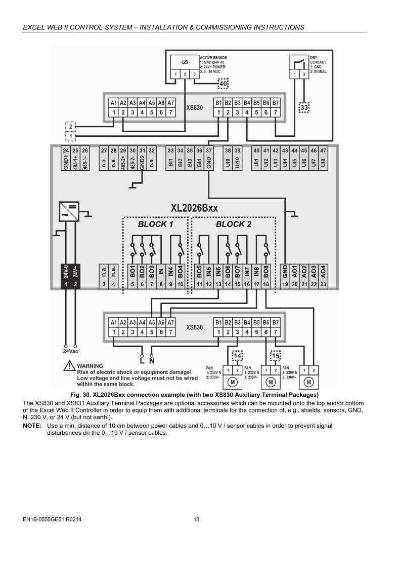
Fig. 30. XL2026Bxx connection example (with two XS830 Auxiliary Terminal Packages)
The XS830 and XS831 Auxiliary Terminal Packages are optional accessories which can be mounted onto the top and/or bottom of the Excel Web II Controller in order to equip them with additional terminals for the connection of, e.g., shields, sensors, GND, N, 230 V, or 24 V (but not earth!).
NOTE: Use a min. distance of 10 cm between power cables and 0…10 V / sensor cables in order to prevent signal disturbances on the 0…10 V / sensor cables.

EXCEL WEB II CONTROL SYSTEM – INSTALLATION & COMMISSIONING INSTRUCTIONS
19 EN1B-0555GE51 R0214
Internal I/Os of the Excel Web II The XL2000Bxx is not equipped with inputs or outputs. The following sub-sections thus apply only to the XL2026Bxx and XL2014BxB.
Universal Inputs The XL2026Bxx is equipped with ten (XL2014BxB: four) universal inputs (UIs) configurable (in CARE). For information on the accuracy of the sensor inputs, their differential measurement error, the characteristics (i.e., resistances and resultant voltages in dependence upon tem-perature) of the various different sensor types which can be connected to them, and on the thresholds at which sensor failures are recognized, see section “Appendix 2” on page 38.
Table 13. Specifications of UIs
criteria value
voltage input UI1-UI10: 0 … 10 VDC with pull-up resistor
UI1-UI8: 0…10 VDC w/o pull-up resistor
UI1-UI8: 2…10 VDC w/o pull-up resistor
current input UI1-UI10: 0 … 10 VDC w/o pull-up resistor, external 499Ω resistor required to measure 0…20 mA
UI1-UI8: 2…10 VDC w/o pull-up resistor, external 499Ω resistor required to measure 4…20 mA
supported sensor types
NTC20kΩ (-50…+150 °C; default)
Slow binary input (static, dry-contact)
resolution 12-bit resolution
accuracy ±75 mV (0 ... 10 V)
protection against short-circuiting, 24 VAC
200 kVi
GND
Fig. 31 Internal wiring of UI1-UI8 configured for voltage input (without pull-up resistor)
200 k
25 k
10 VDC
Vi
GND
Fig. 32. Internal wiring of UI1-UI10 configured for input from NTC20kΩ or voltage input (with pull-up resistor)
Analog Outputs The XL2026Bxx is equipped with four (XL2014BxB: two) analog outputs (AOs). In the event of an application stop (e.g., during application download), the analog outputs assume the safety positions configured in CARE. The analog outputs can be configured in CARE as binary outputs (with an output of 0 V or 10 V, as the case may be).
Table 14. Specifications of AOs
criteria value
output type 0…10 V
2…10 V
max. output range 0 … 11 VDC (1 mA) (default)
min. resolution 8 bit
min. accuracy ± 150 mV
max. wire length 400 m
wire cross section See Table 9 on pg. 14.
protection against short-circuiting, 24 VAC
Binary Inputs / Pulse Counters The XL2026Bxx and the XL2014BxB are equipped with four binary inputs (static dry-contact inputs) / pulse counters (fast totalizers).
Table 15. Specifications of BIs
criteria value
input type binary input (static dry-contact)
pulse counter (fast totalizer)
current rating (closed input)
2 mA
open contact voltage
24 VDC
protection against short-circuiting, 24 VAC
Binary Input Specifications The binary inputs of the Excel Web II are static dry-contact inputs. This reduces the wiring effort, as it is then not necessary to distribute an auxiliary voltage signal.
open circuit ≥ 3000 Ω (24 VDC on BI terminal)
closed circuit ≤ 500 Ω (short-circuit current: 2.0 mA)

EXCEL WEB II CONTROL SYSTEM – INSTALLATION & COMMISSIONING INSTRUCTIONS
EN1B-0555GE51 R0214 20
The polarity (normal = N.O. contact or reverse = N.C. contact) configuration defines if a logical 1 or a logical 0 is detected for a closed contact. This is done by selecting (in CARE) one of the following options:
normal (default) closed external contact → state=1
open external contact → state=0
reverse closed external contact → state=0
open external contact → state=1
Pulse Counter Specifications Using CARE, the binary inputs of the Excel Web II can be configured as pulse counters (fast totalizers) for operation in conjunction with devices equipped with an open collector output. If the duty cycle is 50% / 50%, the pulse counter supports up to 15 Hz. Counting is done on the rising edge.
Table 16. BIs of Excel Web II configured as fast totalizers
frequency max. 15 Hz
pulse ON min. 25 ms
pulse OFF min. 25 ms
bounce max. 5 ms
COMFAST
TOTALIZER
DRY CONTACT24 VDC =
0 V =
BI
24V
openclosed
GND
Fig. 33. Internal wiring of BI
Binary Outputs The features eight (XL2026Bxx) or four (XL2014BxB) binary outputs arranged in two blocks (BO1…4 and BO5..8, respectively).
WARNING
Risk of electric shock or equipment damage! Low voltage and line voltage must not be wired within the same block.
In the event of an application stop (e.g., during application download), the binary outputs assume the safety positions configured in CARE. The polarity (normal = N.O. contact or reverse = N.C. contact) configuration defines if a relay is open or closed, depending upon whether there is a logical 1 or a logical 0. This is done by selecting (in CARE) one of the following options:
normal (default) state=1 → relay contact is closed
state=0 → relay contact is opened
reverse state=0 → relay contact is closed
state=1 → relay contact is opened
Table 17. Relay specifications of the Excel Web II
block 1 block 2
BO1…3 BO4 BO5…8
contact volt. AC 5…253 V 5…253 V 5…253 V
contact volt. DC 5…30 V 20…30 V 5…30 V
max. contact cur-rent AC (resistive)
3 A 10 A 3 A
max. contact cur-rent AC (induct.)
0.3 A* 10 A 0.3 A*
max. contact cur-rent AC (induct.)
2 A** 10 A 2 A**
max. contact cur-rent DC
3 A 7 A 3 A
min. load 100 mA /
5 Vdc 40 mA / 24 Vdc
100 mA /5 Vdc
* typically 250,000 cycles; ** typically 50,000 cycles
NOTE: The total max. sum load for all binary outputs (BO1…8) equals 14 A.
NOTE: Binary output 4 supports the switching of high in-rush currents (e.g., motors, incandescent lights, etc.). The max. allowed switch current is 80 A for a duration of max. 20 ms.

EXCEL WEB II CONTROL SYSTEM – INSTALLATION & COMMISSIONING INSTRUCTIONS
21 EN1B-0555GE51 R0214
ENGINEERING, COMMISSIONING Please refer also to CARE User Guide (Product Literature No.: EN2B-0182GE51) for detailed information.
Required Preparations In order to access (with a laptop or PC) the Excel Web II Controller via Ethernet/IP for the first time, you may employ any one of the following two options:
Option 1: USB 2.0 Device (recommended) This USB 2.0 Device interface is the recommended interface for downloading applications and firmware via CARE. An “A-Male to B-Male” USB cable is required.
Fig. 34. A-male to B-male USB cable
For access via USB, the Excel Web II Controller has a permanent default IP address 192.168.255.241. Your PC's IP address must match the Excel Web II Controller's default IP address subnet: We recommend using DHCP or “Obtain an automatic IP address”.
Option 2: Standard Ethernet Interface The standard IP address can be set in CARE. For this purpose, connect first with the USB interface. In any case, your PC's IP address must match the Excel Web II Con-troller's default IP address subnet. We recommend using DHCP or “Obtain an automatic IP address”.

EXCEL WEB II CONTROL SYSTEM – INSTALLATION & COMMISSIONING INSTRUCTIONS
EN1B-0555GE51 R0214 22
EXTRA PARTS Table 18. Extra parts
order number description
TPU-45-01 Removable terminal plugs, push-in type; complete set of 9 plugs (for terminals 1 - 47); for the XL2026Bxx.
TPU-11-01 Removable terminal plugs, push-in type; complete set of 3 plugs (for terminals 1 - 47); for the XL2000Bxx.
MVC-80-AC1 Terminal cover (color: RAL9011); package of 10; for Excel Web II Controllers.
MVC-80-AC2 Front door mounting accessory (color: RAL9011); package of 10; for Excel Web II Controllers.
MVC-40-AC3 Strain relief; package of ten; for Excel Web II Controllers.
A1 A2 A3 A4 A5 A6 A7 A8 A9 B1 B2 B3 B4 B5 B6 B7 B8 B9 XS830
Set of ten packages. Each Auxiliary Terminal Package consists of two groups of nine internally connected push-in terminals, for distributing signals / power. For the Mixed Panel Bus I/O Module and the Excel Web II Controller, only. Please refer to Honeywell I/O Modules - Installation & Commissioning Instructions (EN1B-0556GE51) for more information.
A1 B1 A2 B2 A3 B3 A4 B4 G1 G2A5 B5 A6 B6 A7 B7 A8 B8 XS831
Set of ten packages. Each Auxiliary Terminal Package consists of two groups of four pairs of push-in terminals (each with a 499 Ω resistor), for converting 0…20 mA signals into 0…10 VDC signals, and one push-in ground terminal per group. Please refer to Honeywell I/O Modules - Installation & Commissioning Instructions (EN1B-0556GE51) for more information.
XL2000HMI-A External HMI with LCD display which derives needed electrical energy from the Excel Web II controller. Suitable for connection to the RJ45 socket on the front of the XL2000B3A, XL2014B3B, and XL2026B3A. .

EXCEL WEB II CONTROL SYSTEM – INSTALLATION & COMMISSIONING INSTRUCTIONS
23 EN1B-0555GE51 R0214
PANEL BUS CONNECTION The Excel Web II Controller features two RS485 interfaces to which Panel Bus modules can be connected: RS485-1 (consisting of push-in terminals 24 [GND-1], 25, and 26) and/or RS485-2 (consisting of push-in terminals 29, 30, and 31 [GND-2]).
NOTE: GND-2 is internally connected with 24V-0 (terminal 1) and system GND (terminals 19+37)
Overview of Panel Bus I/O Modules
XS821-22XSU821-22
XS823XSU823
XS824-25XSU824-25Excel Web II
PANEL BUSPANEL BUS PANEL BUS PANEL BUS
PANEL BUS I/OELECTRONIC
MODULES
pluggableANALOG OUTPUT
pluggableANALOG INPUT
pluggableBINARY INPUT
pluggableFLOATINGOUTPUT
XF821A
XFR822A
XF822A XF823A
pluggableRELAY OUTPUT
XFR824A XFR825A
XF824A
MIXED I/Os(with integrated electronic module)
1 2 3 4 5 6 7 8 9 10 11 12
B1 B2 B3 B4 B5 B6
B12
12
6
B11
11
5
B10
10
4
B9
9
3
B8
8
2
B7
7
1
DI
Binary Inputs
G1 G2
41 42
GND Analog Outputs
AI2 AI3 AI4
14 15 16
AI1
17 18 19 20
13
Analog InputsAO5
AO1
AO6
AO2
AO7
AO3
AO8
AO4
21
25 26 27 28
22 23 24
DO
24V Relays
NO1 NO2 NO3 NO4 NO5 NO6
CO1 CO2 CO3 CO4 CO5 CO6
35
29 30 31 32 33 34
36 37 38 39 40
1 2 3 4 5 6Install. Instr.MU1B-0473GE51
!
AI5 AI6 AI7 AI8
Honeywell
1 2 3 4 5 6 7 8 9 10 11 12
B1 B2 B3 B4 B5 B6
B12
12
6
B11
11
5
B10
10
4
B9
9
3
B8
8
2
B7
7
1
DI
Binary Inputs
G1 G2
41 42
GND Analog Outputs
AI2 AI3 AI4
14 15 16
AI1
17 18 19 20
13
Analog Inputs
AO5
AO1
AO6
AO2
AO7
AO3
AO8
AO4
21
25 26 27 28
22 23 24
DO
24V Relays
NO1 NO2 NO3 NO4 NO5 NO6
CO1 CO2 CO3 CO4 CO5 CO6
35
29 30 31 32 33 34
36 37 38 39 40
1 2 3 4 5 6Install. Instr.MU1B-0473GE51
!
AI5 AI6 AI7 AI8
Honeywell
XF830A
XF830AXF831A
XF831A
Fig. 35. Overview of Panel Bus I/O Modules
Panel Bus Considerations RS485-1 (isolated)
- Max. Panel Bus length:
o 40 meters. Any type of cabling and topology (including star topology) possible. No additional end termination permitted.
o 800 meters. Mandatory twisted-pair or telephone cable and daisy chain topology. The Excel Web II Controller must be positioned at one end of the Panel Bus, and an end termination (120 Ω) at the other end. Further, the three-position slide switch (see Fig. 12 on pg. 8) must be set to "END."
RS485-2 (non-isolated) - Max. Panel Bus length:
o 40 meters. Any type of cabling and topology (including star topology) possible. No additional end termination permitted.
o 800 meters. Mandatory twisted-pair or telephone cable and daisy chain topology. The Excel Web II Controller must be positioned at one end of the Panel Bus, and an end termination (120 Ω) at the other end.
- Must not extend beyond a single building or building floor.
Max. no. of Panel Bus I/O modules per RS485 interface - Max. no. of Panel Bus I/O modules of a given model: 16.
- Total max. no. of Panel Bus I/O modules: 64.
Max. no. of Panel Bus I/O modules per Excel Web II - Max. no. of Panel Bus I/O modules of a given model: 32.
- Total max. no. of Panel Bus I/O modules: 128.
Max. no. of hardware I/O points + NVs per Excel Web II: 600 - Max. no. of mapped NVs allowed per Excel Web II is thus 600 minus the no. of hardware I/O points.
Refer to Honeywell I/O Modules - Installation & Commissioning Instructions (EN1B-0556GE51) for more information about connection, current requirements, power supply, overvoltage protection, cable specifications, fusing, effects of manual overrides, etc. of Honeywell I/O modules and field devices connected to them.
EXCEL WEB II CONTROL SYSTEM – INSTALLATION & COMMISSIONING INSTRUCTIONS
EN1B-0555GE51 R0214 24
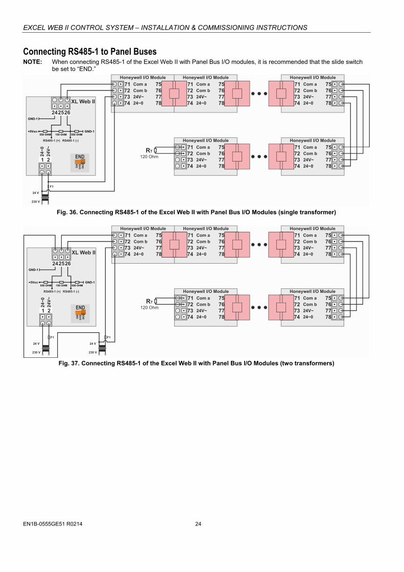
Connecting RS485-1 to Panel Buses NOTE: When connecting RS485-1 of the Excel Web II with Panel Bus I/O modules, it is recommended that the slide switch
be set to “END.”
1 2
Com a71 7572 7673 7774 78
Com b
24V~
24
V~
24~0
24
~0
Honeywell I/O Module
Com a71 7572 7673 7774 78
Com b
24V~
24~0
Com a71 7572 7673 7774 78
Com b
24V~
24~0
Com a71 7572 7673 7774 78
Com b
24V~
24~0
Com a71 7572 7673 7774 78
Com b
24V~
24~0
XL Web II
F1
GND-1
GND-1+5VISO
END
END
BIA
SM
ID
RS485-1 (+) RS485-1 (-)
242526
230 V
24 V
550 OHM 550 OHM150 OHM
RT
120 Ohm
Honeywell I/O Module
Honeywell I/O Module
Honeywell I/O Module
Honeywell I/O Module
Fig. 36. Connecting RS485-1 of the Excel Web II with Panel Bus I/O Modules (single transformer)
1 2
Com a71 7572 7673 7774 78
Com b
24V~
24V
~
24~0
24~
0
Com a71 7572 7673 7774 78
Com b
24V~
24~0
Com a71 7572 7673 7774 78
Com b
24V~
24~0
Com a71 7572 7673 7774 78
Com b
24V~
24~0
Com a71 7572 7673 7774 78
Com b
24V~
24~0
230 V 230 V
24 V 24 V
F1 F1
END
END
BIA
SM
ID
GND-1
GND-1+5VISO
RS485-1 (+) RS485-1 (-)
242526
550 OHM 550 OHM150 OHM
RT
120 Ohm
XL Web II
Honeywell I/O Module Honeywell I/O Module
Honeywell I/O Module
Honeywell I/O Module
Honeywell I/O Module
Fig. 37. Connecting RS485-1 of the Excel Web II with Panel Bus I/O Modules (two transformers)
EXCEL WEB II CONTROL SYSTEM – INSTALLATION & COMMISSIONING INSTRUCTIONS
25 EN1B-0555GE51 R0214
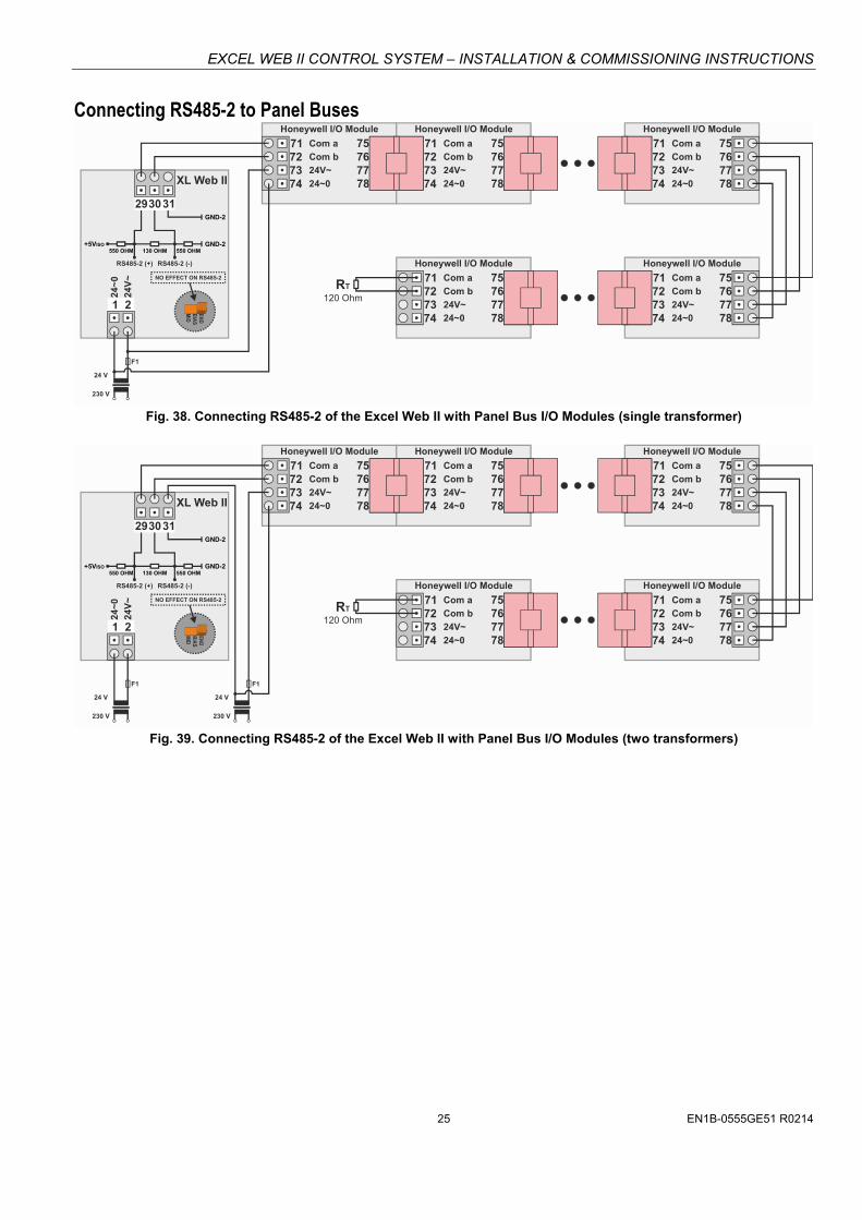
Connecting RS485-2 to Panel Buses
1 2
Com a71 7572 7673 7774 78
Com b
24V~
24V
~
24~0
24~
0
Com a71 7572 7673 7774 78
Com b
24V~
24~0
Com a71 7572 7673 7774 78
Com b
24V~
24~0
Com a71 7572 7673 7774 78
Com b
24V~
24~0
Com a71 7572 7673 7774 78
Com b
24V~
24~0
F1
293031
230 V
24 V
GND-2
GND-2+5VISO
RS485-2 (+) RS485-2 (-)
550 OHM 550 OHM130 OHM
RT
120 Ohm
END
BIA
SM
ID
NO EFFECT ON RS485-2
XL Web II
Honeywell I/O Module Honeywell I/O Module
Honeywell I/O Module
Honeywell I/O Module
Honeywell I/O Module
Fig. 38. Connecting RS485-2 of the Excel Web II with Panel Bus I/O Modules (single transformer)
1 2
Com a71 7572 7673 7774 78
Com b
24V~
24
V~
24~0
24
~0
Com a71 7572 7673 7774 78
Com b
24V~
24~0
Com a71 7572 7673 7774 78
Com b
24V~
24~0
Com a71 7572 7673 7774 78
Com b
24V~
24~0
Com a71 7572 7673 7774 78
Com b
24V~
24~0
F1
293031
230 V
24 V
230 V
24 V
F1
GND-2
GND-2+5VISO
RS485-2 (+) RS485-2 (-)
550 OHM 550 OHM130 OHM
RT
120 Ohm
END
BI A
SM
ID
NO EFFECT ON RS485-2
XL Web II
Honeywell I/O Module Honeywell I/O Module
Honeywell I/O Module
Honeywell I/O Module
Honeywell I/O Module
Fig. 39. Connecting RS485-2 of the Excel Web II with Panel Bus I/O Modules (two transformers)

EXCEL WEB II CONTROL SYSTEM – INSTALLATION & COMMISSIONING INSTRUCTIONS
EN1B-0555GE51 R0214 26
Cable Specifications Panel Bus I/O Modules When checking the length of the power supply cable, the connection cables to all Panel Bus I/O Modules must be taken into account.
Table 19. Power supply cable specifications
max. length 3 m (from transformer to final module)
cross section min. 0.75 mm2 (AWG 18)
EIA 485 Cable Specifications The following cable specification is valid for all EIA 485 buses (e.g., Panel Bus and BACnet MS/TP).
Table 20. EIA 485 cable specifications
max. length 1000 m
cable type twisted pair, shielded (foil or braided shields are acceptable)
characteristic impedance
100…130 Ω
distributed capac-itance between conductors
Less than 100 pF per meter (30 pF per foot)
distributed capac-itance between conductors and shield
Less than 200 pF per meter (60 pF per foot)
The following cables fulfill this requirement:
AWG 18;
J-Y-(St)-Y 2 x 2 x 0,8;
CAT 5,6,7 cable (use only one single pair for one bus);
Belden 9842 or 9842NH.
Field Devices Depending on the distance from the controller, field devices can be supplied with power by the same transformer used for the Panel Bus I/O Modules, or by a separate transformer, using cables as specified in Table 21.
Table 21. Power / communication cable specifications
type of signal
cross-sectional area
100 m (Fig. 28)single transformer
400 m (Fig. 27) sep. transformers
24 VAC power 1.5 mm2 (16 AWG) not allowed for > 100 m (300 ft)
0…10 V signals 0.081 – 2.08 mm2 (28 – 14 AWG)
For wiring field devices, see section “Powering Panel Bus I/O Modules and Field Devices” on page 16.
Routing Cables to Field Devices Route low-voltage signal and output cables to field devices separately from mains cables.
Table 22. Minimum distances to power mains cables
cable min. distance
shielded 10 mm (0.4 in.)
unshielded 100 mm (4 in.)
All low-voltage signal and output cables should be regarded as communication circuits in accordance with VDE 0100 and VDE 0800 (or NEC or other equivalent).
If the general guidelines for cable routing are observed, it is not necessary to shield field device signal and power supply cables.
If, for whatever reason, the routing guidelines cannot be observed, the field device signal and power supply cables must be shielded.
– Shielding of cables leading to field devices must be grounded only at one end.
– Do not connect the shield to the Excel Web II Controller.
EXCEL WEB II CONTROL SYSTEM – INSTALLATION & COMMISSIONING INSTRUCTIONS
27 EN1B-0555GE51 R0214
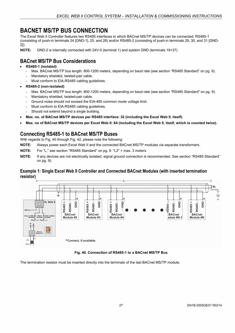
BACNET MS/TP BUS CONNECTION The Excel Web II Controller features two RS485 interfaces to which BACnet MS/TP devices can be connected: RS485-1 (consisting of push-in terminals 24 [GND-1], 25, and 26) and/or RS485-2 (consisting of push-in terminals 29, 30, and 31 [GND-2]).
NOTE: GND-2 is internally connected with 24V-0 (terminal 1) and system GND (terminals 19+37)
BACnet MS/TP Bus Considerations RS485-1 (isolated)
˗ Max. BACnet MS/TP bus length: 800-1200 meters, depending on baud rate (see section “RS485 Standard” on pg. 9). ˗ Mandatory shielded, twisted-pair cable. ˗ Must conform to EIA-RS485 cabling guidelines.
RS485-2 (non-isolated)
˗ Max. BACnet MS/TP bus length: 800-1200 meters, depending on baud rate (see section "RS485 Standard" on pg. 9). ˗ Mandatory shielded, twisted-pair cable. ˗ Ground noise should not exceed the EIA-485 common mode voltage limit. ˗ Must conform to EIA-RS485 cabling guidelines. ˗ Should not extend beyond a single building.
Max. no. of BACnet MS/TP devices per RS485 interface: 32 (including the Excel Web II, itself).
Max. no of BACnet MS/TP devices per Excel Web II: 64 (including the Excel Web II, itself, which is counted twice).
Connecting RS485-1 to BACnet MS/TP Buses With regards to Fig. 40 through Fig. 42, please note the following:
NOTE: Always power each Excel Web II and the connected BACnet MS/TP modules via separate transformers.
NOTE: For “L,” see section “RS485 Standard” on pg. 9. "L2" = max. 3 meters.
NOTE: If any devices are not electrically isolated, signal ground connection is recommended. See section “RS485 Standard” on pg. 9).
Example 1: Single Excel Web II Controller and Connected BACnet Modules (with inserted termination resistor)
1 2
24V
~
24~
0
242526
F1
230 V
24 V
L
GND-1
GND-1
+5VISO
RS485-1 (+) RS485-1 (-)
550 kOHM 150 kOHM 550 kOHM
END
END
BIA
SM
IDBACnetModule #1
BACnetModule #2
RS
485
+
RS
485
-
GN
D
BACnetModule #3
BACnetModule #4
BACnetModule #N-1
BACnetModule #N
RS
485
+
RS
485
+
RS
485
+
RS
485
-
RS
485
-
GN
D
GN
D
GN
D
Connect, if available.
RT
120 Ohm
L2
RS
485
-
RS
485
+
RS
485
-
GN
DXL Web II
Fig. 40. Connection of RS485-1 to a BACnet MS/TP Bus
The termination resistor must be inserted directly into the terminals of the last BACnet MS/TP module.
EXCEL WEB II CONTROL SYSTEM – INSTALLATION & COMMISSIONING INSTRUCTIONS
EN1B-0555GE51 R0214 28
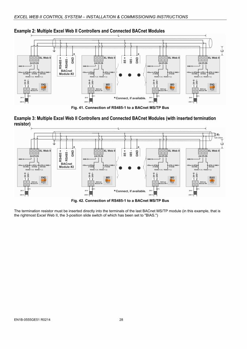
Example 2: Multiple Excel Web II Controllers and Connected BACnet Modules
1 11 12 22 2
24V
~
24V
~
24V
~
24V
~
24~
0
24~
0
24~
0
24~
0
24 2425 2526 26
BACnetModule #2
RS
485
+
RS
485
-
GN
DBACnet
Module #4
RS
485
+
RS
485
-
GN
D
F1 F1F1 F1
230 V 230 V230 V 230 V
24 V 24 V24 V 24 V
L
GND-1 GND-1
+5VISO +5VISO
RS485-1 (+) RS485-1 (+)RS485-1 (-) RS485-1 (-)
47 kOHM 47 kOHM
END
END
BIA
SM
ID
END
END
BIA
SM
ID
END
BIA
SM
ID
MID
END
BIA
SM
ID
MID
24 2425 2526 26
GND-1 GND-1
GND-1 GND-1
+5VISO +5VISO
RS485-1 (+) RS485-1 (+)RS485-1 (-) RS485-1 (-)
550 OHM 550 OHM150 OHM 150 OHM550 OHM 550 OHM
Connect, if available.
BACnetModule #1
BACnetModule #3
BACnetModule #N-1
BACnetModule #N
L2
GND-147 kOHM
GND-147 kOHM
XL Web II XL Web II XL Web II XL Web II
Fig. 41. Connection of RS485-1 to a BACnet MS/TP Bus
Example 3: Multiple Excel Web II Controllers and Connected BACnet Modules (with inserted termination resistor)
1 11 12 22 2
24V
~
24V
~
24V
~
24V
~
24~
0
24~
0
24~
0
24~
024 2425 2526 26
RS
485
+
RS
48
5 -
GN
D
BACnetModule
RS
485
+
RS
48
5 -
GN
D
F1 F1F1 F1
230 V 230 V230 V 230 V
24 V 24 V24 V 24 V
L
GND-1 GND-1
+5VISO +5VISO
RS485-1 (+) RS485-1 (+)RS485-1 (-) RS485-1 (-)
47 kOHM 47 kOHM
END
END
BIA
SM
ID
END
BIA
SM
ID
MID
END
BIA
SM
ID
MID
24 2425 2526 26
GND-1
GND-1 GND-1
+5VISO +5VISO
RS485-1 (+) RS485-1 (+)RS485-1 (-) RS485-1 (-)
550 OHM 550 OHM150 OHM 550 OHMGND-1
550 OHMGND-1
47 kOHMGND-1
47 kOHM
Connect, if available.
BACnetModule #1
BACnetModule #N
L2
END
BIA
SM
ID
BIAS
RT
120 Ohm
BACnetModule #2
BACnetModule #3
BACnetModule #N-1
XL Web II XL Web II XL Web II XL Web II
Fig. 42. Connection of RS485-1 to a BACnet MS/TP Bus
The termination resistor must be inserted directly into the terminals of the last BACnet MS/TP module (in this example, that is the rightmost Excel Web II, the 3-position slide switch of which has been set to "BIAS.")

EXCEL WEB II CONTROL SYSTEM – INSTALLATION & COMMISSIONING INSTRUCTIONS
29 EN1B-0555GE51 R0214
Connecting RS485-2 to BACnet MS/TP Buses With regards to Fig. 43 and Fig. 44, please note the following:
NOTE: Always power each Excel Web II and the connected BACnet MS/TP modules via separate transformers.
NOTE: For “L,” see section “RS485 Standard” on pg. 9. "L2" = max. 3 meters.
NOTE: If any devices are not electrically isolated, signal ground connection is recommended. See section “RS485 Standard” on pg. 9).
NOTE: Between devices equipped with non-isolated RS485 bus interfaces, potential differences of max. ±7 V are allowed. Further, this bus should not extend beyond a single building.
Example 1: Single Excel Web II Controller and Connected BACnet Modules (with inserted termination resistor)
1 2
24V
~
24~
0
Excel Web II
293031GND-2
GND-2+5V
RS485-2 (+) RS485-2 (-)
550 OHM 550 OHM130 OHM
F1
230 V
24 V
RT
BACnetModule #2
RS
485
+
RS
48
5 -
GN
D
BACnetModule #3
BACnetModule #4
BACnetModule #N-1
BACnetModule #N
120 Ohm
RS
485
+
RS
485
+
RS
485
+
RS
485
+
RS
48
5 -
RS
48
5 -
RS
48
5 -
RS
48
5 -
GN
D
GN
D
GN
D
GN
D
L
L2
Connect, if available.
BACnetModule #1
END
BI A
SM
ID
NO EFFECT ON RS485-2
Fig. 43. Connection of RS485-2 to a BACnet MS/TP Bus
The termination resistor must be inserted directly into the terminals of the last BACnet MS/TP module.
Example 2: Multiple Excel Web II Controllers and Connected BACnet Modules
1 12 2
24V
~
24V
~
24~
0
24~
0
29 2930 3031 31GND-2 GND-2
GND-2 GND-2+5V +5V
RS485-2 (+) RS485-2 (+)RS485-2 (-) RS485-2 (-)
550 OHM 550 OHM550 OHM 550 OHM130 OHM 130 OHM
F1 F1
230 V 230 V
24 V 24 V
1 12 2
24V
~
24V
~
24~
0
24~
0
24 2425 2526 26
RS
485
+
RS
48
5 -
GN
D
BACnetModule
RS
485
+
RS
48
5 -
GN
D
F1 F1
230 V 230 V
24 V 24 V
L
GND-1 GND-1
+5VISO +5VISO
RS485-1 (+) RS485-1 (+)RS485-1 (-) RS485-1 (-)
47 kOHM 47 kOHM
END
BIA
SM
ID
MID
END
BIA
SM
ID
MID
Connect, if available.
L2
GND-147 kOHM
GND-147 kOHM
BACnetModule #1
BACnetModule #2
BACnetModule #3
BACnetModule #N-1
BACnetModule #N
END
BI A
SM
ID
NO EFFECT ON RS485-2
END
BIA
SM
ID
NO EFFECT ON RS485-2
Excel Web II Excel Web II Excel Web II Excel Web II
Fig. 44. Connection of RS485-2 to a BACnet MS/TP Bus
EXCEL WEB II CONTROL SYSTEM – INSTALLATION & COMMISSIONING INSTRUCTIONS
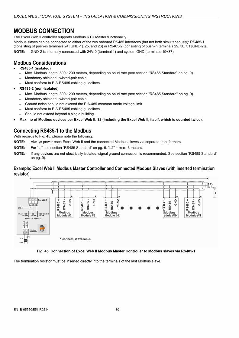
EN1B-0555GE51 R0214 30
MODBUS CONNECTION The Excel Web II controller supports Modbus RTU Master functionality. Modbus slaves can be connected to either of the two onboard RS485 interfaces (but not both simultaneously): RS485-1 (consisting of push-in terminals 24 [GND-1], 25, and 26) or RS485-2 (consisting of push-in terminals 29, 30, 31 [GND-2]).
NOTE: GND-2 is internally connected with 24V-0 (terminal 1) and system GND (terminals 19+37)
Modbus Considerations RS485-1 (isolated)
˗ Max. Modbus length: 800-1200 meters, depending on baud rate (see section “RS485 Standard” on pg. 9). ˗ Mandatory shielded, twisted-pair cable. ˗ Must conform to EIA-RS485 cabling guidelines.
RS485-2 (non-isolated)
˗ Max. Modbus length: 800-1200 meters, depending on baud rate (see section "RS485 Standard" on pg. 9). ˗ Mandatory shielded, twisted-pair cable. ˗ Ground noise should not exceed the EIA-485 common mode voltage limit. ˗ Must conform to EIA-RS485 cabling guidelines. ˗ Should not extend beyond a single building.
Max. no of Modbus devices per Excel Web II: 32 (including the Excel Web II, itself, which is counted twice).
Connecting RS485-1 to the Modbus With regards to Fig. 45, please note the following:
NOTE: Always power each Excel Web II and the connected Modbus slaves via separate transformers.
NOTE: For “L,” see section “RS485 Standard” on pg. 9. "L2" = max. 3 meters.
NOTE: If any devices are not electrically isolated, signal ground connection is recommended. See section “RS485 Standard” on pg. 9).
Example: Excel Web II Modbus Master Controller and Connected Modbus Slaves (with inserted termination resistor)
1 2
24V
~
24~
0
242526
F1
230 V
24 V
L
GND-1
GND-1
+5VISO
RS485-1 (+) RS485-1 (-)
550 OHM 150 OHM 550 OHM
END
END
BIA
SM
IDModbusModule #1
ModbusModule #2
RS
485
+
RS
485 -
GN
D
ModbusModule #3
ModbusModule #4
ModbusModule #N-1
ModbusModule #N
RS
485
+
RS
485
+
RS
485
+
RS
485 -
RS
485 -
GN
D
GN
D
GN
D
Connect, if available.
RT
120 Ohm
L2
RS
485 -
RS
485
+
RS
485 -
GN
DXL Web II
Fig. 45. Connection of Excel Web II Modbus Master Controller to Modbus slaves via RS485-1
The termination resistor must be inserted directly into the terminals of the last Modbus slave.
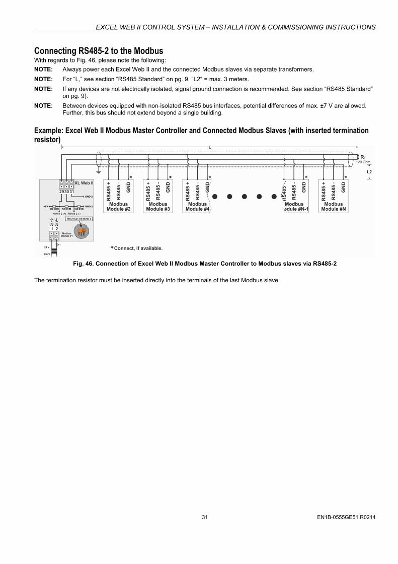
EXCEL WEB II CONTROL SYSTEM – INSTALLATION & COMMISSIONING INSTRUCTIONS
31 EN1B-0555GE51 R0214
Connecting RS485-2 to the Modbus With regards to Fig. 46, please note the following:
NOTE: Always power each Excel Web II and the connected Modbus slaves via separate transformers.
NOTE: For “L,” see section “RS485 Standard” on pg. 9. "L2" = max. 3 meters.
NOTE: If any devices are not electrically isolated, signal ground connection is recommended. See section “RS485 Standard” on pg. 9).
NOTE: Between devices equipped with non-isolated RS485 bus interfaces, potential differences of max. ±7 V are allowed. Further, this bus should not extend beyond a single building.
Example: Excel Web II Modbus Master Controller and Connected Modbus Slaves (with inserted termination resistor)
1 2
24V
~
24~
0
293031GND-2
GND-2+5V
RS485-2 (+) RS485-2 (-)
550 OHM 550 OHM130 OHM
F1
230 V
24 V
RT
ModbusModule #2
RS
485
+
RS
48
5 -
GN
D
ModbusModule #3
ModbusModule #4
ModbusModule #N-1
ModbusModule #N
120 Ohm
RS
485
+
RS
485
+
RS
485
+
RS
485
+
RS
48
5 -
RS
48
5 -
RS
48
5 -
RS
48
5 -
GN
D
GN
D
GN
D
GN
D
L
L2
Connect, if available.
ModbusModule #1
END
BI A
SM
ID
NO EFFECT ON RS485-2
XL Web II
Fig. 46. Connection of Excel Web II Modbus Master Controller to Modbus slaves via RS485-2
The termination resistor must be inserted directly into the terminals of the last Modbus slave.
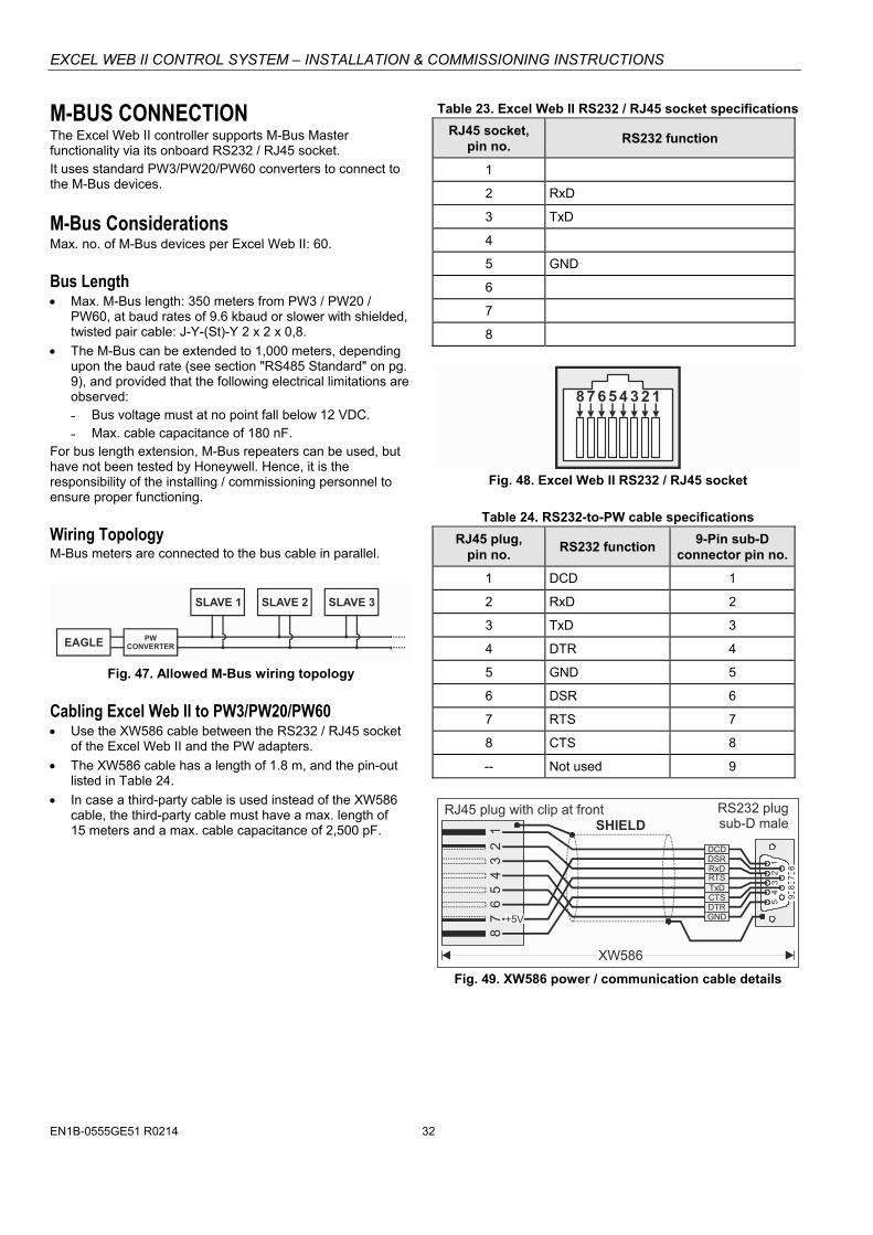
EXCEL WEB II CONTROL SYSTEM – INSTALLATION & COMMISSIONING INSTRUCTIONS
EN1B-0555GE51 R0214 32
M-BUS CONNECTION The Excel Web II controller supports M-Bus Master functionality via its onboard RS232 / RJ45 socket. It uses standard PW3/PW20/PW60 converters to connect to the M-Bus devices.
M-Bus Considerations Max. no. of M-Bus devices per Excel Web II: 60.
Bus Length Max. M-Bus length: 350 meters from PW3 / PW20 /
PW60, at baud rates of 9.6 kbaud or slower with shielded, twisted pair cable: J-Y-(St)-Y 2 x 2 x 0,8.
The M-Bus can be extended to 1,000 meters, depending upon the baud rate (see section "RS485 Standard" on pg. 9), and provided that the following electrical limitations are observed: ˗ Bus voltage must at no point fall below 12 VDC. ˗ Max. cable capacitance of 180 nF.
For bus length extension, M-Bus repeaters can be used, but have not been tested by Honeywell. Hence, it is the responsibility of the installing / commissioning personnel to ensure proper functioning.
Wiring Topology M-Bus meters are connected to the bus cable in parallel.
EAGLE
SLAVE 1 SLAVE 2 SLAVE 3
PWCONVERTER
Fig. 47. Allowed M-Bus wiring topology
Cabling Excel Web II to PW3/PW20/PW60 Use the XW586 cable between the RS232 / RJ45 socket
of the Excel Web II and the PW adapters.
The XW586 cable has a length of 1.8 m, and the pin-out listed in Table 24.
In case a third-party cable is used instead of the XW586 cable, the third-party cable must have a max. length of 15 meters and a max. cable capacitance of 2,500 pF.
Table 23. Excel Web II RS232 / RJ45 socket specifications
RJ45 socket, pin no.
RS232 function
1
2 RxD
3 TxD
4
5 GND
6
7
8
8 7 6 5 4 3 2 1
Fig. 48. Excel Web II RS232 / RJ45 socket
Table 24. RS232-to-PW cable specifications
RJ45 plug, pin no.
RS232 function 9-Pin sub-D
connector pin no.
1 DCD 1
2 RxD 2
3 TxD 3
4 DTR 4
5 GND 5
6 DSR 6
7 RTS 7
8 CTS 8
-- Not used 9
1
5
4
3 2
9 8
7
6
12
36
78
45
RS232 plugsub-D maleSHIELD
DCDDSRRxDRTSTxDCTSDTRGND
XW586
RJ45 plug with clip at front
+5V
Fig. 49. XW586 power / communication cable details

EXCEL WEB II CONTROL SYSTEM – INSTALLATION & COMMISSIONING INSTRUCTIONS
33 EN1B-0555GE51 R0214
Cabling PW3/PW20/PW60 to M-Bus Use shielded, twisted pair cable J-Y-(St)-Y 2 x 2 x 0,8.
Shielding is especially recommended when the M-Bus cable is installed in areas with expected or actual electro-magnetic noise. Avoiding such areas is to be preferred.
Connect the shield to a noise-free earth ground – only once per M-Bus connection.
M-Bus Connection Procedure 1. Install the PW M-Bus Adapter on DIN rail. Insert a
screwdriver into the slot in the DIN rail clamp on the underside of the PW and pry downward to loosen clamp until the unit snaps onto the rail.
1
2
3
DIN RAIL
Fig. 50. Mounting of PW (PW3 shown here)
2. Connect the M-Bus devices to the PW M-Bus Adapter. All M+ and M- terminals are connected in parallel in the PW M-Bus Adapter.
XW586
INSERTMETER-BUSWIRES
INSERT POWERSUPPLY WIRES
Fig. 51. PW M-Bus adapter connections
3. Connect the PW M-Bus Adapter to the RS232 / RJ45 socket of the Excel Web II using the XW586 cable.
J1J8
END
BIA
SM
ID
XW586
Excel Web II
RS232 / RJ45SOCKET
M-BUSDEVICE
Fig. 52. Connecting the Excel Web II to the PW M-Bus
adapter
4. Connect 24 V power to the M-Bus Adapter.
IMPORTANT If the same transformer is used for the Excel Web II controller, then you must ensure that V+ on the PW M-Bus Adapter has the same potential as terminal 2 (24 V~) of the Excel Web II controller!
V+ 2V- 1
PW3 Excel Web II
230 VacFUSE
0 Vac0 Vac24 Vac
Fig. 53. Connecting power to the PW M-Bus adapter
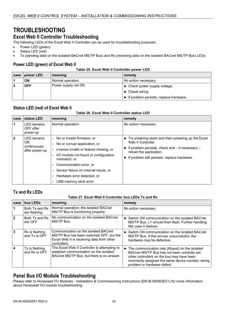
EXCEL WEB II CONTROL SYSTEM – INSTALLATION & COMMISSIONING INSTRUCTIONS
EN1B-0555GE51 R0214 34
TROUBLESHOOTING Excel Web II Controller Troubleshooting The following LEDs of the Excel Web II Controller can be used for troubleshooting purposes: Power LED (green) Status LED (red) Tx (sending data on the isolated BACnet MS/TP Bus) and Rx (receiving data on the isolated BACnet MS/TP Bus) LEDs
Power LED (green) of Excel Web II Table 25. Excel Web II Controller power LED
case power LED meaning remedy
1 ON Normal operation No action necessary.
2 OFF Power supply not OK. Check power supply voltage.
Check wiring.
If problem persists, replace hardware.
Status LED (red) of Excel Web II Table 26. Excel Web II Controller status LED
case status LED meaning remedy
1 LED remains OFF after power-up
Normal operation. No action necessary.
2 LED remains ON continuously after power-up
– No or invalid firmware, or
– No or corrupt application, or
– License invalid or feature missing, or
– I/O module not found or configuration mismatch, or
– Communication error, or
– Sensor failure on internal inputs, or
– Hardware error detected, or
– USB memory stick error.
Try powering down and then powering up the Excel Web II Controller.
If problem persists, check and – if necessary – reload the application.
If problem still persists, replace hardware.
Tx and Rx LEDs Table 27. Excel Web II Controller bus LEDs Tx and Rx
case bus LEDs meaning remedy
1 Both Tx and Rx are flashing
Normal operation; the isolated BACnet MS/TP Bus is functioning properly.
No action necessary
2 Both Tx and Rx are OFF
No communication on the isolated BACnet MS/TP Bus.
Switch ON communication on the isolated BACnet MS/TP Bus. L1 should then flash. Further handling like case 4 (below).
3 Rx is flashing and Tx is OFF
Communication on the isolated BACnet MS/TP Bus has been switched OFF, but the Excel Web II is receiving data from other controllers.
Switch ON communication on the isolated BACnet MS/TP Bus. If this proves unsuccessful, the hardware may be defective.
4 Tx is flashing and Rx is OFF
The Excel Web II Controller is attempting to establish communication on the isolated BACnet MS/TP Bus, but there is no answer.
The communication rate (Kbaud) on the isolated BACnet MS/TP Bus has not been correctly set; other controllers on the bus may have been incorrectly assigned the same device number; wiring problem or hardware defect.
Panel Bus I/O Module Troubleshooting Please refer to Honeywell I/O Modules - Installation & Commissioning Instructions (EN1B-0556GE51) for more information about Honeywell I/O module troubleshooting.
EXCEL WEB II CONTROL SYSTEM – INSTALLATION & COMMISSIONING INSTRUCTIONS
35 EN1B-0555GE51 R0214
APPENDIX 1: EARTH GROUNDING Excel Web II Systems and SELV In order to avoid distribution of noise or earth ground potential differences over networks or other connections, the Excel Web II Controller is designed to be in compliance with SELV (Safety Extra-Low Voltage). Furthermore, SELV offers the greatest possible safety against electrical impact. To support SELV, all Honeywell external (CRT series) or internal transformers comply with standard EN60742. Earth grounding is therefore not recommended.
Excel Web II Systems and Standard EN60204-1 However, if compliance with EN60204-1 is required, note the following:
General Information about EN60204-1 EN60204-1 defines electrical safety for a complete application/machine including controllers, sensors, actuators and any connected/controlled electrical device. EN60204-1 requires controllers to be powered by PELV (Protective Extra-Low Voltage) and earth grounding of the secondary side of the used transformers or earth grounding of the system ground. Earth grounding is prescribed to prevent unexpected start-up of connected rotating/moving machines due to an insulation fault and double earth grounding somewhere in the plant. In order to fulfill PELV (if earth grounding is prohibited), the use of an earth leakage monitor is also possible.
When is EN60204-1 Applicable to Excel Web II Systems? Safety against electrical impact
– EN60204-1 is not mandatory; this is because electrical safety is provided by the use of SELV and transformers according to standard EN60742.
Safety against unexpected start-up of rotating/moving machines
– If the application/plant does not contain machines that can be harmful to the operator due to an unexpected start-up, the standard EN60204-1 is not applicable.
If such machines are encountered, then EN60204-1 must be followed. Grounding is required.
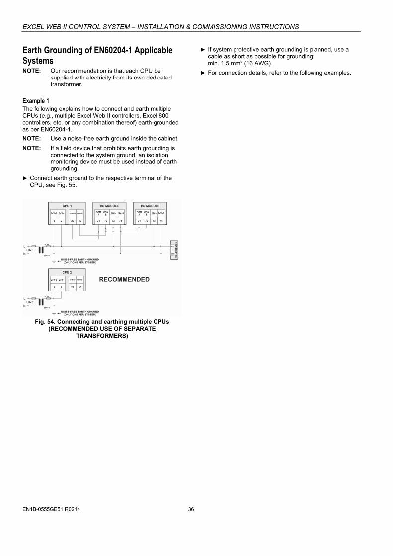
EXCEL WEB II CONTROL SYSTEM – INSTALLATION & COMMISSIONING INSTRUCTIONS
EN1B-0555GE51 R0214 36
Earth Grounding of EN60204-1 Applicable Systems NOTE: Our recommendation is that each CPU be
supplied with electricity from its own dedicated transformer.
If system protective earth grounding is planned, use a cable as short as possible for grounding: min. 1.5 mm² (16 AWG).
For connection details, refer to the following examples.
Example 1 The following explains how to connect and earth multiple CPUs (e.g., multiple Excel Web II controllers, Excel 800 controllers, etc. or any combination thereof) earth-grounded as per EN60204-1.
NOTE: Use a noise-free earth ground inside the cabinet.
NOTE: If a field device that prohibits earth grounding is connected to the system ground, an isolation monitoring device must be used instead of earth grounding.
Connect earth ground to the respective terminal of the CPU, see Fig. 55.
24 V~
24 V~
24 V~0
24 V~0
LINE
LINE
L
L
N
N
CPU 1
29 30
RS485-2 + RS485-2 - COMB
COMB
NOISE-FREE EARTH GROUND(ONLY ONE PER SYSTEM)
NOISE-FREE EARTH GROUND(ONLY ONE PER SYSTEM)
COMA
COMA
74 7472 7273 7371 71
24V~ 24V~24V~0 24V~0
21
24V~24V~0
CPU 2
29 30
RS485-2 + RS485-2 -
21
24V~24V~0
I/O MODULE I/O MODULE
GND
FIE
LD
DE
VIC
E
24 V~
Y
RECOMMENDED
Fig. 54. Connecting and earthing multiple CPUs
(RECOMMENDED USE OF SEPARATE TRANSFORMERS)
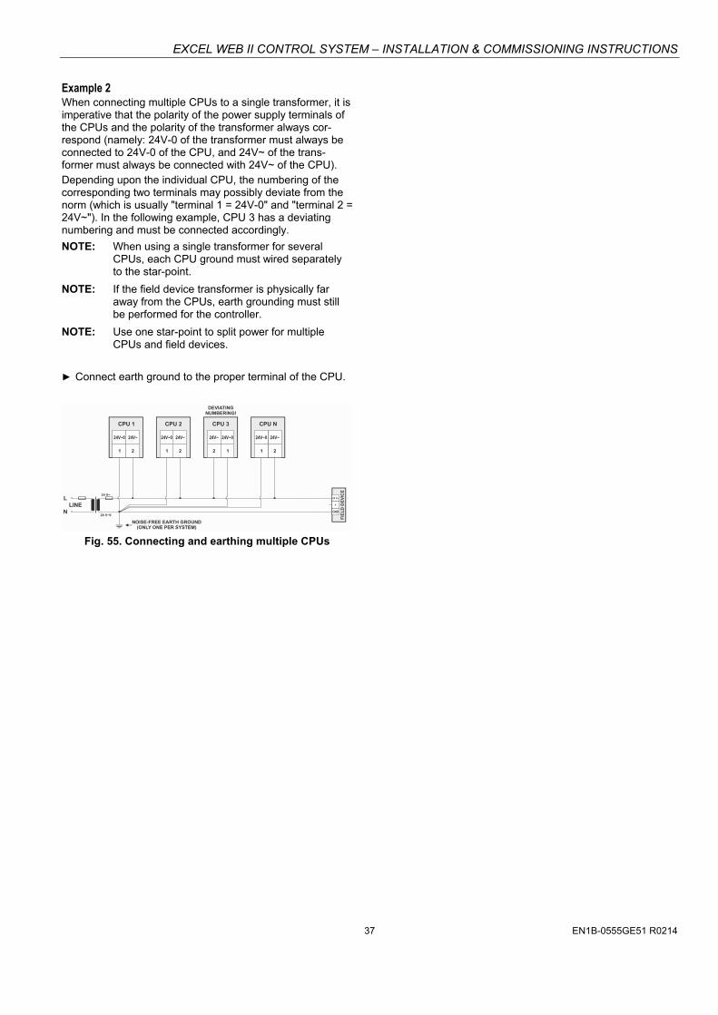
EXCEL WEB II CONTROL SYSTEM – INSTALLATION & COMMISSIONING INSTRUCTIONS
37 EN1B-0555GE51 R0214
Example 2 When connecting multiple CPUs to a single transformer, it is imperative that the polarity of the power supply terminals of the CPUs and the polarity of the transformer always cor-respond (namely: 24V-0 of the transformer must always be connected to 24V-0 of the CPU, and 24V~ of the trans-former must always be connected with 24V~ of the CPU). Depending upon the individual CPU, the numbering of the corresponding two terminals may possibly deviate from the norm (which is usually "terminal 1 = 24V-0" and "terminal 2 = 24V~"). In the following example, CPU 3 has a deviating numbering and must be connected accordingly.
NOTE: When using a single transformer for several CPUs, each CPU ground must wired separately to the star-point.
NOTE: If the field device transformer is physically far away from the CPUs, earth grounding must still be performed for the controller.
NOTE: Use one star-point to split power for multiple CPUs and field devices.
Connect earth ground to the proper terminal of the CPU.
24 V~
24 V~0
LINEL
N
CPU 1 CPU 2 CPU 3 CPU N
NOISE-FREE EARTH GROUND(ONLY ONE PER SYSTEM)
2 2 2 21 1 1 1
24V~ 24V~ 24V~ 24V~24V~0 24V~0 24V~0 24V~0
GND
FIE
LD
DE
VIC
E
24 V~
Y
DEVIATINGNUMBERING!
Fig. 55. Connecting and earthing multiple CPUs

EXCEL WEB II CONTROL SYSTEM – INSTALLATION & COMMISSIONING INSTRUCTIONS
EN1B-0555GE51 R0214 38
APPENDIX 2 Sensor Input Accuracy The internal sensor inputs of the Excel Web II Controller support NTC20kΩ sensors (see also section “Universal Inputs” on page 19). The following table lists the typical minimum accuracies of the hardware and software for temperature sensors.
Table 28. Accuracies of internal NTC20kΩ sensor inputs of the Excel Web II
range measurement error (excl. sensor characteristics)
-50 … -20 °C (-58 … -4 °F) ≤ 5.0 K
-20 … 0 °C (-4 … +32 °F) ≤ 1.0 K
0 … 30 °C (32 … 86 °F) ≤ 0.3 K
30 … 70 °C (86 … 158 °F) ≤ 0.5 K
70 … 100 °C (158 … 212 °F) ≤ 1.0 K
100 … 130 °C (212 … 266 °F) ≤ 3.0 K
130 … 150 °C (266 … 302 °F) ≤ 5.5 K
150 … 400 °C (302 … 752 °F) --
NOTE: This is the accuracy of the internal sensor input (hardware + software [linearization]), only. This table does not include the characteristics of the sensors, themselves (see section “Sensor Characteristics” below). If a different sensor or sensor accuracy is required, one may instead use the inputs of, e.g., a connected Panel I/O module.
Recognition of Sensor Failure of Sensor Inputs The thresholds at which sensor failures – i.e., sensor breaks (SB) and short-circuits (SC) – are recognized depends upon the given sensor type. In the event of a recognized sensor failure, the sensor inputs assume the safety values configured in CARE. Table 29 lists the measurement ranges and the corresponding thresholds for the recognition of sensor failure for the various different sensor types:
Table 29. Thresholds for short-circuit (SC) and sensor-break (SB) recognition
I/O configuration measurement range recognition thresholds
2…10 V 2…10 V / 4…20 mA (without pull-up) SC: < 1.5 V / 3 mA; SB: no recognition
NTC20kΩ -50 … +150 °C SC: < 20 Ω; SB: < -70 °C
NOTE: In the case of temperatures lying outside the aforementioned ranges, the lowest/highest value within the range, instead, will be communicated. Thus a temperature of -51 °C will be communicated as “-50 °C.”
Sensor Characteristics The characteristics (resistance in relation to temperature) of the sensors and the resultant voltage are listed on the following pages. The stated values do not include failures due to: sensor failures; wiring resistance or wiring failures; misreadings due to a meter connected to measure resistance or voltage at the input.
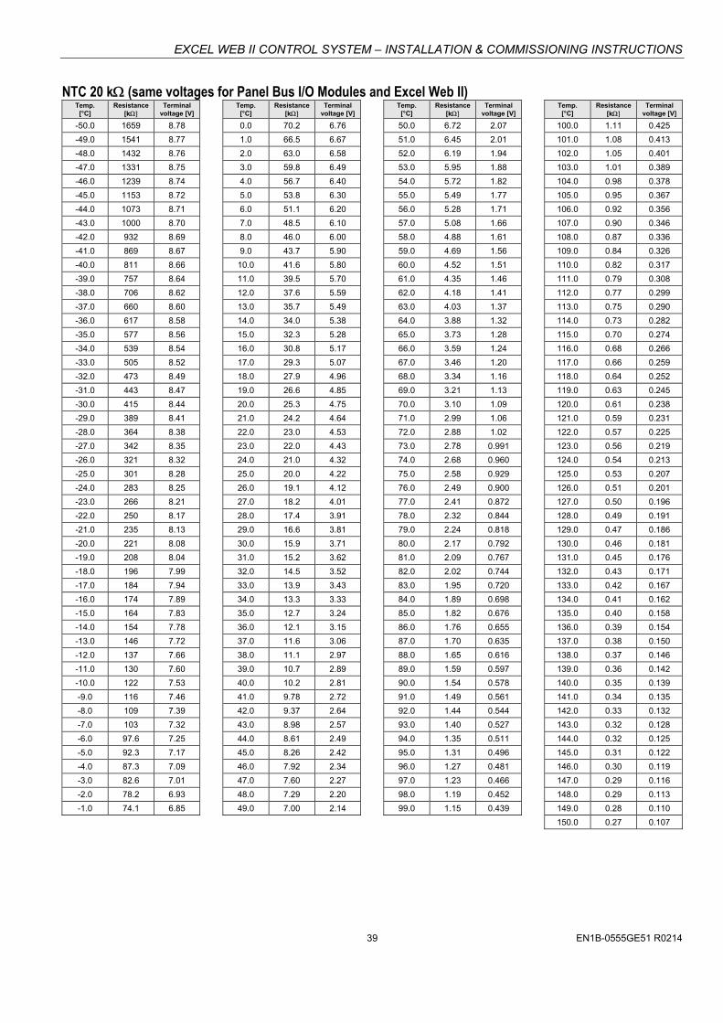
EXCEL WEB II CONTROL SYSTEM – INSTALLATION & COMMISSIONING INSTRUCTIONS
39 EN1B-0555GE51 R0214
NTC 20 k (same voltages for Panel Bus I/O Modules and Excel Web II) Temp.
[°C] Resistance
[k Terminal
voltage [V]
-50.0 1659 8.78
-49.0 1541 8.77
-48.0 1432 8.76
-47.0 1331 8.75
-46.0 1239 8.74
-45.0 1153 8.72
-44.0 1073 8.71
-43.0 1000 8.70
-42.0 932 8.69
-41.0 869 8.67
-40.0 811 8.66
-39.0 757 8.64
-38.0 706 8.62
-37.0 660 8.60
-36.0 617 8.58
-35.0 577 8.56
-34.0 539 8.54
-33.0 505 8.52
-32.0 473 8.49
-31.0 443 8.47
-30.0 415 8.44
-29.0 389 8.41
-28.0 364 8.38
-27.0 342 8.35
-26.0 321 8.32
-25.0 301 8.28
-24.0 283 8.25
-23.0 266 8.21
-22.0 250 8.17
-21.0 235 8.13
-20.0 221 8.08
-19.0 208 8.04
-18.0 196 7.99
-17.0 184 7.94
-16.0 174 7.89
-15.0 164 7.83
-14.0 154 7.78
-13.0 146 7.72
-12.0 137 7.66
-11.0 130 7.60
-10.0 122 7.53
-9.0 116 7.46
-8.0 109 7.39
-7.0 103 7.32
-6.0 97.6 7.25
-5.0 92.3 7.17
-4.0 87.3 7.09
-3.0 82.6 7.01
-2.0 78.2 6.93
-1.0 74.1 6.85
Temp. [°C]
Resistance[k
Terminal voltage [V]
0.0 70.2 6.76
1.0 66.5 6.67
2.0 63.0 6.58
3.0 59.8 6.49
4.0 56.7 6.40
5.0 53.8 6.30
6.0 51.1 6.20
7.0 48.5 6.10
8.0 46.0 6.00
9.0 43.7 5.90
10.0 41.6 5.80
11.0 39.5 5.70
12.0 37.6 5.59
13.0 35.7 5.49
14.0 34.0 5.38
15.0 32.3 5.28
16.0 30.8 5.17
17.0 29.3 5.07
18.0 27.9 4.96
19.0 26.6 4.85
20.0 25.3 4.75
21.0 24.2 4.64
22.0 23.0 4.53
23.0 22.0 4.43
24.0 21.0 4.32
25.0 20.0 4.22
26.0 19.1 4.12
27.0 18.2 4.01
28.0 17.4 3.91
29.0 16.6 3.81
30.0 15.9 3.71
31.0 15.2 3.62
32.0 14.5 3.52
33.0 13.9 3.43
34.0 13.3 3.33
35.0 12.7 3.24
36.0 12.1 3.15
37.0 11.6 3.06
38.0 11.1 2.97
39.0 10.7 2.89
40.0 10.2 2.81
41.0 9.78 2.72
42.0 9.37 2.64
43.0 8.98 2.57
44.0 8.61 2.49
45.0 8.26 2.42
46.0 7.92 2.34
47.0 7.60 2.27
48.0 7.29 2.20
49.0 7.00 2.14
Temp. [°C]
Resistance[k
Terminal voltage [V]
50.0 6.72 2.07
51.0 6.45 2.01
52.0 6.19 1.94
53.0 5.95 1.88
54.0 5.72 1.82
55.0 5.49 1.77
56.0 5.28 1.71
57.0 5.08 1.66
58.0 4.88 1.61
59.0 4.69 1.56
60.0 4.52 1.51
61.0 4.35 1.46
62.0 4.18 1.41
63.0 4.03 1.37
64.0 3.88 1.32
65.0 3.73 1.28
66.0 3.59 1.24
67.0 3.46 1.20
68.0 3.34 1.16
69.0 3.21 1.13
70.0 3.10 1.09
71.0 2.99 1.06
72.0 2.88 1.02
73.0 2.78 0.991
74.0 2.68 0.960
75.0 2.58 0.929
76.0 2.49 0.900
77.0 2.41 0.872
78.0 2.32 0.844
79.0 2.24 0.818
80.0 2.17 0.792
81.0 2.09 0.767
82.0 2.02 0.744
83.0 1.95 0.720
84.0 1.89 0.698
85.0 1.82 0.676
86.0 1.76 0.655
87.0 1.70 0.635
88.0 1.65 0.616
89.0 1.59 0.597
90.0 1.54 0.578
91.0 1.49 0.561
92.0 1.44 0.544
93.0 1.40 0.527
94.0 1.35 0.511
95.0 1.31 0.496
96.0 1.27 0.481
97.0 1.23 0.466
98.0 1.19 0.452
99.0 1.15 0.439
Temp. [°C]
Resistance[k
Terminal voltage [V]
100.0 1.11 0.425
101.0 1.08 0.413
102.0 1.05 0.401
103.0 1.01 0.389
104.0 0.98 0.378
105.0 0.95 0.367
106.0 0.92 0.356
107.0 0.90 0.346
108.0 0.87 0.336
109.0 0.84 0.326
110.0 0.82 0.317
111.0 0.79 0.308
112.0 0.77 0.299
113.0 0.75 0.290
114.0 0.73 0.282
115.0 0.70 0.274
116.0 0.68 0.266
117.0 0.66 0.259
118.0 0.64 0.252
119.0 0.63 0.245
120.0 0.61 0.238
121.0 0.59 0.231
122.0 0.57 0.225
123.0 0.56 0.219
124.0 0.54 0.213
125.0 0.53 0.207
126.0 0.51 0.201
127.0 0.50 0.196
128.0 0.49 0.191
129.0 0.47 0.186
130.0 0.46 0.181
131.0 0.45 0.176
132.0 0.43 0.171
133.0 0.42 0.167
134.0 0.41 0.162
135.0 0.40 0.158
136.0 0.39 0.154
137.0 0.38 0.150
138.0 0.37 0.146
139.0 0.36 0.142
140.0 0.35 0.139
141.0 0.34 0.135
142.0 0.33 0.132
143.0 0.32 0.128
144.0 0.32 0.125
145.0 0.31 0.122
146.0 0.30 0.119
147.0 0.29 0.116
148.0 0.29 0.113
149.0 0.28 0.110
150.0 0.27 0.107

EXCEL WEB II CONTROL SYSTEM – INSTALLATION & COMMISSIONING INSTRUCTIONS
Manufactured for and on behalf of the Environmental and Combustion Controls Division of Honeywell Technologies Sàrl, Rolle, Z.A. La Pièce 16, Switzerland by its Authorized Representative: Automation and Control Solutions Honeywell GmbH Böblinger Strasse 17 71101 Schönaich / Germany Phone: (49) 7031 63701 Fax: (49) 7031 637493 http://ecc.emea.honeywell.com Subject to change without notice. Printed in Germany EN1B-0555GE51 R0214
INDEX accuracies see sensor input accuracies
BACnet BACnet IP 3 BACnet MS/TP 3 BACnet MS/TP via RS485-1 9, 28, 29, 30
LEDs 9, 35 troubleshooting 35
BACnet MS/TP via RS485-2 9, 34 Honeywell BACnet architecture 6
BACnet IP LED 8 via Ethernet / RJ45 socket 5
BACnet MS/TP via RS485-1 5, 7, 32 LEDs 5
BACnet MS/TP via RS485-2 5, 7 disposal
WEEE Directive 2002/96/EC 2 Ethernet / RJ45 socket 7
details 8 Ethernet Interface
protocol version 3 External HMI
details 23 RJ45 socket 5, 7, 13, 14
extra parts External HMI 23 MVC-40-AC3 strain relief 23 MVC-80-AC1 terminal cover 23 MVC-80-AC2 front door mounting accessory 23 TPU-11-01 removable push-in terminal plugs 15, 23 TPU-45-01 removable push-in terminal plugs 15, 23 XS830 Auxiliary Terminal Package 19, 23 XS831 Auxiliary Terminal Package 19, 23
fusing 15 LEDs 7
BACnet MS/TP LED troubleshooting 9, 35
L1 5, 9 L2 5, 9 power LED 5, 9
troubleshooting 35 status LED 5, 9
troubleshooting 35 M-Bus
connection 33
Modbus connection 11, 31 via RS485-1 5, 7, 31 via RS485-2 5, 7, 32
Panel Bus connection 24
multiple rails, single transformer 25, 26 via RS485-1 5, 9 via RS485-2 5, 9
power supply failure indication 35
power supply (field devices) cable specifications 27 via Excel Web II 17 via I/O module 17 via I/O module via Excel Web II 17
power supply (Panel Bus I/Os) cable specifications 27
RS232 / RJ45 socket 7, 8 safety
electrical safety as per EN60204-1 36 general safety information 2, 15 PELV 36 SELV 36
safety values/positions safety positions of AOs 20 safety positions of relays 21 safety values of sensor inputs 39
sensor characteristics NTC 20 kOhm 40
sensor input accuracies 20, 39 AOs 20 UIs 20
USB USB 2.0 Device Interface 5, 7
details 8 initially accessing Excel Web II via Ethernet/IP 22
USB 2.0 Host Interface 5, 7 connection of IF-LON 8 details 8 LED 9
XS830 Auxiliary Terminal Package connection example 19
XW-Online 7, 8