executive summary
TRANSCRIPT

SIEMENS LTD
Project Executive
ET HS

EXECUTIVE SUMMARY OF 400KV
SWITCHYARD ( MUNDRA)
FIRST UMPP OF INDIA
TRANSMISSION SUBSTATIONS AND SWITCHYARD
CONTROL & PROTECTION

Contents
1. Summary of the project
2. Drawings list of switchyard
3. Quality work of the switchyard
4. Testing kit
5. Application of the equipment
6. SCADA system
7. Transformer oil standard
8. Inspection procedure of the equipments
9. Stringing of HV Line
10. Project issue
11. Documents of the project
12. Project management function
13. Nature of TQM

Summary of the projects
Since 6-Jun-2011, I am working with M/s siemens ltd as project executive of 400kv switch yard on Mundra project. There are so many quality points raised by the clients such as Improper earthing, cable laying, cable tray erection, bolting, painting ,Rusting of the structural material, jump ring of moose wire and progress etc. these are the points which is pinching company management and disturbing the site progress. As per my Boss instruction I have stars my work and found that switchyard is in very bad condition earth strip of the tower, equipment is not connected to the specified position and not touch the equipment body. Earth pits of the switchyard is hearting the siemens status and quality, same condition of the above mentioned points. I have feel that , I am going to face the very challenging job on this site. Man power is also a very big problem for me because the balance erection work is also in pick situation. We are behind the progress curve. Material management of site is very bad, on site no body is taking responsibility to take to maintain the material handling.

TYPICAL SUBSTATION DRAWINGS LIST1.Coversheet/index and legends2.Elementary one line diagram3.Relay one line diagram4.General arrangement of plan site plan, section and details5.Substation plan section and details6.Foundation plan and details7.Structure plan and details8.Grounding plan and details9.Raceway plan and details10.Ducts bank and high voltage cable plan details11.Controll building plan , section and details12.Relay control panels lay out and wiring diagram13.Three line diagram and ac and dc scam tics14.Equipment yard external connection diagram15.Clamps and connectors diagram16.Cable schedule17.Emergency supply diagram18.Utility diagram

Earthing and earth pit work

Bolting of tower and equipment structure

1.POLARITY TESTER-
To measure the CT Polarity.2.HV TRANSFORMER-To inject high voltage
for testing like KPV of CT and Ratio for CVT
3.LOADING TRANSFORMER
Equipment for measure the Ratio of CT
4.TANDELTA KIT-To measure
the value of Capacitance and
Tan delta for CVT,REACTAR
and LA
5.INSULATION RESISTANCE METER To measure the Insulation resistance value of
CT,CVT,LA,ISOLATOR,BREAKER,REACTAR
EMVT,WAVE TRAPER and CABLES
6.DC POWER PACK-To provide DC source
for Testing of Auxiliary Relay Testing
7.TRANSFORMER WINDING
RESISTANCE METER-TO measure the
value of Transformer Winding
Resistance
8.Tongue Tester- To measure small value of
Current and voltage for CT Ratio and KPV
CVT Ratio.
9.SECONDARY INJECTOR TEST KIT
10.Transformer Oil Tester
SAT KIT DESCRIPTION

CURRENT TRANSFORMER
CT are of two types : live tank, dead tank.• in live tank the ct primary & secondary are on top.• in dead tank ct the primary is on top and secondary cores are on bottom
of tank.• Steps down high current to low current for two reasons mainly
measurement & protection purpose.• The secondary current for all ct is commonly 1 or 2 amps.• The no of secondary cores depends on recruitment mainly 2 ,4 or 5 etc.• For measurement purpose separate core should be used because of
100% accuracy is needed..• the material used for secondary of metering ct is nickel iron alloy.• the material used for secondary of protection ct is grain oriented silicon
steel.• Note: The secondary cores of ct should never be opened because of high
voltage will be at the terminal.
.

APPLICATION OF CT.B
Protection C.T.
Measuring C.T.
1.Isolate measurement & control ckt. From high voltage
2.Measur current for power measurement and control
3.Perform ckt. Control, protection and current limiting
4.Signaling for dis. Protection, tariff metering and for BCU
5.Diff. protection
6. Reduce the current to lower level to be measured more easily.
7.Primary current, Load of the current transformer is measured, & secondary is the range of the current8.

LIGHTING ARRESTOR
Application
1.lightning arrester is used to suppress the abnormal voltages which are caused due to lightning etc.
2.LA basically requires a non linear material.
3.It requires high resistance to limit the discharge current.
4.It requires low resistance during surges etc.
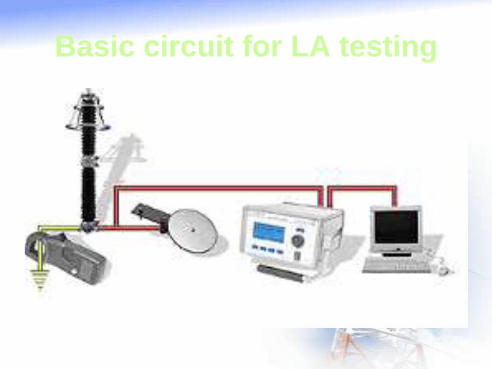
Basic circuit for LA testing

COMUNICATION SYSTEM OF SENDING AND
RECEIVING END SWITCHYARD(A(RED& B(BLUE)
WT CVT CVT WT
PLCCRELAY
BR TRIP TRIP BR
PLCC RELAY
Transmission line

REQUIREMENTS OF PROTECTIVE RELAYS
SENSITIVITY : The relay shall be sensitive to operate for
minimum quantity of operating parameter.
SELECTIVITY: The relay/scheme should be able to select the faulty
section and isolate.
SPEED : The relay should operate faster so that fault is
isolated as fast as possible.
RELIABILITY: The relay/scheme should operate for all types of fault with
repeatability and reliability.
COST: The relay/scheme should be economical .
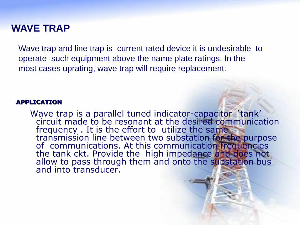
APPLICATION
Wave trap is a parallel tuned indicator-capacitor ‘tank’ circuit made to be resonant at the desired communication frequency . It is the effort to utilize the same transmission line between two substation for the purpose of communications. At this communication frequencies the tank ckt. Provide the high impedance and does not allow to pass through them and onto the substation bus and into transducer.
WAVE TRAP
Wave trap and line trap is current rated device it is undesirable to
operate such equipment above the name plate ratings. In the
most cases uprating, wave trap will require replacement.
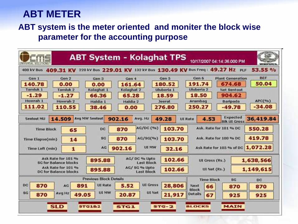
ABT system is the meter oriented and moniter the block wise
parameter for the accounting purpose
ABT METER

ISOLATOR
Application
1.It is used to make or break the circuit under no load condition .
2.Mostly there are two types of isolators: hcb (horizontal centre break), double break etc.
3.Double break isolators is mostly used for low voltage rating.
4.Again these hcb are of two types : gang operated & individual operated per phase).
Note: A isolator cannot be operated under load condition.

CAPACITOR VOLTAGE TRANSFORMER
Application
1.Basically a cvt steps down high voltage to low voltage with help of capacitors. Hence the name capacitor voltage transformer.
2.The secondary terminal voltage of cvt are 63.5v
3.A cvt consists of : 2 coupling capacitors, compensating reactor, step down transformer and Ferro resonance suppression circuit.
4.The use of compensating reactor is to compensate the phase displacement in capaictor elements.
5.Ferro resonance in cvt is due to the capacitor in voltage divider in series with inductance of transformer.
6.The Ferro resonance circuit is brought to resonance by disturbances in network that may saturate the iron core which leads to insulation breakdown.

Application
CIRCUIT BREAKER
.1.It is used to break or make the circuit under both (load & no load) condition.
2.While opening of breaker a huge amount of spark will be at open & closed contacts. For reliable operation of breaker the arc should be extinguished immediately after opening of moving contacts.
3.For arc extinguish mainly : vacuum, sf6,air are used.
4.For low voltage ratings mainly vacuum & air blast breakers are used.
5.For high voltage sf6 breakers are commonly used.
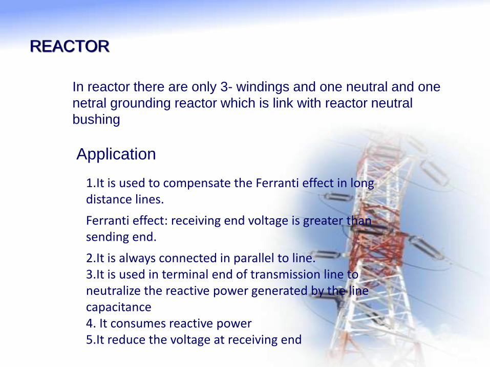
REACTOR
1.It is used to compensate the Ferranti effect in long distance lines.
Ferranti effect: receiving end voltage is greater than sending end.
2.It is always connected in parallel to line.3.It is used in terminal end of transmission line to neutralize the reactive power generated by the line capacitance4. It consumes reactive power5.It reduce the voltage at receiving end
Application
In reactor there are only 3- windings and one neutral and one
netral grounding reactor which is link with reactor neutral
bushing

SCADA SYSTEM
The energy control center receives various type of data from the
power system . This data include breaker status, tap changer
position, amp, voltage, volts, watts, VARs, and other quantities
both digital and analog again data travels over distances ranging
from few miles to several hundred.
In most modern energy control center , the remote data monitoring
and system control function for substation application are
performed by SCADA system.
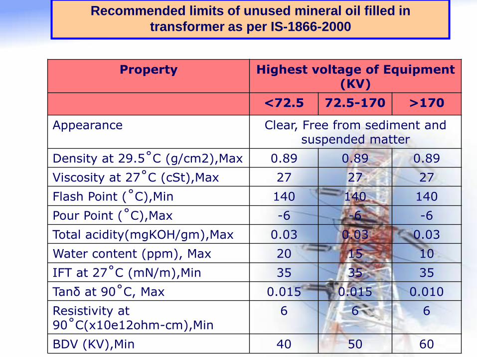
Recommended limits of unused mineral oil filled in
transformer as per IS-1866-2000
Property Highest voltage of Equipment (KV)
<72.5 72.5-170 >170
Appearance Clear, Free from sediment and suspended matter
Density at 29.5˚C (g/cm2),Max 0.89 0.89 0.89
Viscosity at 27˚C (cSt),Max 27 27 27
Flash Point (˚C),Min 140 140 140
Pour Point (˚C),Max -6 -6 -6
Total acidity(mgKOH/gm),Max 0.03 0.03 0.03
Water content (ppm), Max 20 15 10
IFT at 27˚C (mN/m),Min 35 35 35
Tanδ at 90˚C, Max 0.015 0.015 0.010
Resistivity at 90˚C(x10e12ohm-cm),Min
6 6 6
BDV (KV),Min 40 50 60

Recommended limits of used mineral (In Service) oil filled in
transformer as per IS-1866-2000
Property Highest voltage of Equipment (KV)
<72.5 72.5-170 >170
Appearance Clear and without visual contaminations
Water content (ppm), Max No Free water 40 20
BDV (KV),Min 30 40 50
Total acidity(mgKOH/gm),Max 0. 3 0. 3 0. 3
IFT at 27˚C (mN/m),Min 15 15 15
Resistivity at 27˚C(x10e12ohm-cm),Min 1 1 1
Resistivity at 90˚C(x10e12ohm-cm),Min 0.1 0.1 0.1
Tanδ at 90˚C, Max 1.0 1.0 0.2
Flash Point (˚C),Min Maximum decrease of 15˚C from initial value
Sediment and sludge No sediment or precipitable sludge should be detected. Results below 0.02% by mass may
be neglected.

SITE INSPECTION CHECK

STRINGING OF POWER TRANSMISSION LINE
General concept of the sag calculation of the transmission line for extra
high voltage lines, the ground clearance shall be 5.2m plus 0.30m for every
33kV and also consider the atm. Condition such as temperature variation.
Sag in m=(Conductor wt. in kg/m)* square of (span in meter) /8* (tension in
kg)
SPECIAL ISSUES WORKED OUT DURING THE PROJECT
DEVELOPMENT
1.Configuration of bay screens;
2.Configuration and finding solutions for the line differential protections
and line-transformer unit.
CONSTRUCTION AND COMMISSIONING
1.Providing system components at the substation level (FAT- sub-systems)
2.Documentation elaboration and Technical project approval (Technical
Committee TE)
3.Equipping the cubicles and system tests (FAT system )
4.Bay by bay commissioning (procedure and tests SAT)

DOCUMENTATION OF THE PROJECT
1. Tower erection protocol and equipment structure protocol
2. Equipment erection protocol such as CT, BR,CVT,
EMVT,WT,ABT,ISOLATOR ,
3. SAT report of all equipment
Project Management Functions
Scoping – setting the boundaries of the project Planning – identifying the tasks required to complete
the project Estimating – identifying resources required to
complete the project Scheduling – developing a plan to complete the
project Organizing – making sure members understand their
roles and responsibilities Directing – coordinating the project Controlling – monitoring progress Closing – assessing success and failure
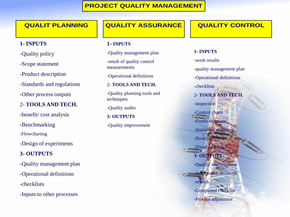
QUALIT PLANNING QUALITY ASSURANCE QUALITY CONTROL
PROJECT QUALITY MANAGEMENT
1- INPUTS
-Quality policy
-Scope statement
-Product description
-Standards and regulations
-Other process outputs
2- TOOLS AND TECH.
-benefit/ cost analysis
-Benchmarking
-Flowcharting
-Design of experiments
3- OUTPUTS
-Quality management plan
-Operational definitions
-checklists
-Inputs to other processes
1- INPUTS
-Quality management plan
-result of quality control
measurements
-Operational definitions
2- TOOLS AND TECH.
-Quality planning tools and
techniques
-Quality audits
3- OUTPUTS
-Quality improvement
1- INPUTS
-work results
-quality management plan
-Operational definitions
-checklists
2- TOOLS AND TECH.
-inspection
-Control charts
-Pareto diagrams
-Statistical sampling
-flowcharting
-Trend analysis
3- OUTPUTS
-Quality improvement
-Acceptance decisions
-rework
-Completed checklist
-Process adjustment

Nature of PQM
Project quality management must address both the management of the project and the product of the project.
Failure to meet quality requirements in either dimension can have serious and negative consequences for any or all of the project stakeholders

Tools and Techniques for Quality Control
Control Charts
1. These charts are graphical representations that display the result of a process over time and are used to determine if the process is “in control”
2. When in control the process should not be adjusted , however it may be changed in order to provide improvements
3. Control charts may be used to monitor any type of output variable
4. Control charts are most often used to monitor repetitive activity in production but can also be used to monitor cost and schedule variances
