executive summaryseniord.ece.iastate.edu/projects/archive/may1017/design... · web viewwind turbine...
TRANSCRIPT

Iowa State University
Wind Turbine Energy Conversion System Design and
IntegrationDesign Document
Project NumberMay10-17
Team MembersBrandon Janssen
Luke LehmanKenny ThelenHassan Burawi
Elsammani Ahmed
AdvisorDr. Venkataramana Ajjarapu
ClientISU Department of Electrical and Computer Engineering
Date SubmittedMonday December 7, 2009
1 | P a g e

DISCLAIMER: This document was developed as a part of the requirements of an Electrical and Computer engineering course at Iowa State University, Ames, Iowa. This document does not constitute a professional engineering design or a professional land surveying document. Although the information is intended to be accurate, the associated students, faculty, and Iowa State University make no claims, promises, or guarantees about the accuracy, completeness, quality, or adequacy of the information. The user of this document shall ensure that any such use does not violate any laws with regard to professional licensing and certification requirements. This use includes any work resulting from this student-prepared document that is required to be under the responsible charge of a licensed engineer or surveyor. This document is copyrighted by the students who produced this document and the associated faculty advisors. No part may be reproduced without the written permission of the Senior Design course coordinator.
2 | P a g e

Table of Contents
Executive Summary.............................................................................................................................5
Problem Statement..............................................................................................................................5
Operating Environment......................................................................................................................6
Intended Users and Uses...................................................................................................................6
Assumptions and Limitations............................................................................................................7
Expected End Product and Deliverables.......................................................................................8
Approach Used.......................................................................................................................................9
Detailed Design...................................................................................................................................11
Overview............................................................................................................................................11
Concept Sketch................................................................................................................................12
Figure 1. Concept Block Diagram................................................................................................12
Wind Turbine....................................................................................................................................13
Figure 2. Wind Turbine......................................................................................................................14
Interface.............................................................................................................................................15
Figure 3. Interface Diagram............................................................................................................15
Controls..............................................................................................................................................16
Inverter...............................................................................................................................................17
Installation.........................................................................................................................................18
Figure 4. Installation Schematic....................................................................................................18
Testing................................................................................................................................................20
Resources and Schedules................................................................................................................21
Summary................................................................................................................................................25
Team Members....................................................................................................................................26
3 | P a g e

List of Figures and TablesFigure 1-Conceptual Sketch 12
Figure 2-Wind Turbine 14
Figure 3-Interface Diagram 15
Figure 4-Installation Schematic 19
Table 1-Wind Turbine Specifications 14
Table 2- Inverter Specifications 15
Table 3-Personal Effort 21
Table 4-Costs 22
4 | P a g e

Executive SummaryWith renewable energy becoming an increasingly popular source for our changing energy and environmental needs, Iowa State University must do its’ part. To show the universities commitment in conserving and minimizing impact on global climate change, a wind turbine will be built on Coover hall.Our team plans to assist in the design and implementation of this wind turbine system, as well as develop it as an educational and demonstration tool for the university. Dr. Ajjarapu wishes to integrate the wind turbine into the coursework for the students at the College of Electrical Engineering. One additional aspect of this project is our involvement in the design of a series of tests to run with the turbine system, a simulation of the system using Matlab, and a display accessible from the web. The general approach of this project is one of collaboration with the previous team as well as research in to new directions for the project to go.Major issues to be resolved include installation of the system, the investigation of alternative components, and implementation of a user interface. The installation of the system has presented us with numerous practical issues. The group has had difficulties acquiring permission from the Iowa State Facilities Planning and Management Department regarding mounting and installation of the system on the roof of Coover Hall. Dr. Ajjarapu has requested research into alternative components that would expand the value and usefulness of the project, in relation to the rest of the costs. One issue yet to be implemented is the addition of a user interface. This would most likely be addressed in the following semester due to the need of an installed system.
Problem Statement
This is a continuation project. The ongoing project involves the design of a wind turbine energy conversion system that can be integrated to electrical power grid in the Coover Hall power lab. The generator is rated around 400W. The wind turbine will be installed along the side of Coover Hall. All the protection and control aspects of the conversion system become part of the design.
The first part of our approach was to gain a full understanding of the requirements and demands of the department with regards to the ongoing project. The second part of our approach is helping the previous design team
5 | P a g e

accomplish their design and implementation goals. Only then can our project move forward due to critical interfacing requirements.
The extension of the project includes the design requirements to supply stand alone load in conjunction with the grid supply. At low wind speeds the system is supplemented from the grid automatically. The extension also includes developing the wind turbine as an educational tool for professors and students.
Operating EnvironmentThe wind turbine and control system will be installed outside Coover Hall on an exterior brick wall. Most of the system will be subjected to the weather conditions typical to central Iowa. This includes temperatures ranging from -30° to 100°+ F and extreme weather conditions such as rain, sleet, snow, dust, and high winds. The system components located on the outside of Coover will be designed to withstand all of these conditions.The rest of the system including the inverter and other test equipment will be located inside one of the power labs in Coover Hall. It must be located in an area of lower traffic so it will not be a disturbance in labs or other activities but accessible for demonstration and testing.Under current installation difficulties, the primary operating environment has changed from the intended location at the side of Coover Hall to the Power Electronics Lab located inside the building.
Intended Users and Uses
Intended Users: The wind turbine system will be used in part by the entire Coover faculty and staff since it will assist in powering the building. It is hoped to be used by professors and students as an educational component in the Electrical Engineering curriculum. Ideally these users will have a background in power systems and maintenance of mechanical systems.Intended Uses:The wind turbine system’s primary use is to supplement power to Coover or a standalone load inside Coover. It will not be expected to supply power in the event of an outage to the entirety of Coover. Another primary goal of this system is to provide an educational component to courses at Iowa State University, as well as a system for research and demonstration.
6 | P a g e

Assumptions and Limitations
Initial AssumptionsThe first assumption our group must make is that the previous team (which is in their second semester of the course) will complete their objectives stated in their project plan. This includes the mounting of the wind turbine, the design and implementation of their control system, and the integration of the wind turbine into the power grid with the use of an inverter. Our second assumption is that the system will operate as specified in the previous group’s plan including output voltage and power.Updated AssumptionsSome of the objectives of the previous will not be completed; this includes the mounting and installation of the turbine system as well as a complete design of a user interface. Another assumption is that the turbine system will be approved for installation, but may include different components. Initial Limitations:Our budget ($250) will be much more strictly enforced because of the large initial cost of this project. The location of our testing equipment will be a limitation due to the availability of lab space. The amount of standalone load we can operate without grid supplementation is also a limitation due to the turbine’s 400W peak output.The system will not be tested for high-wind speeds (excess of 45 m.p.h.) We also cannot test for a grid outage (powering off Coover is not an option). Updated LimitationsFor the current semester we are limited to primitive testing of the partial system. Our testing has been limited to simulated wind speeds instead of actual wind speeds due to our location constraints.
7 | P a g e

Expected End Product and Deliverables
Wind turbine power for standalone loadThe wind turbine (complete with control systems) will be able to operate a standalone load of our choosing (such as an induction motor)Wind turbine power for grid operationThe wind turbine will be able to supplement power to Coover Hall as a whole using a grid connection.Series of tests for Wind Turbine SystemA series of lab-based tests will be designed to aid in the education of Electrical Engineering students. These tests will be designed in order to maximize the value of the wind turbine system. These tests could also serve for demonstration purposes outside of class work.Matlab simulation of wind turbine system (optional)An optional Matlab simulation may be developed to test and develop the system prior to implementing the wind turbine at Coover Hall. This simulation should be accurate and robust to show the impact the wind turbine would have along with any problems unforeseen.User Interface for DisplayA graphical user interface will be developed to aid in the testing and demonstration of the system. This display should include power and voltage levels along with turbine speed and related parameters.
8 | P a g e

Approach Used
Overall Design ObjectivesThe overall design objective is to supplement the Electrical Engineering Department with a tool that will allow students to learn about a wind energy system. It will include a wind turbine system, inverter and control software. Functional requirementsFR01 The turbine will generate a 24V DC output.FR02 The turbine will generate a 400W peak output.FR03 The turbine will supply power to the Coover electric system.FR04 The test-bed connection will serve to facilitate alternative source
connection to the Coover electric system.FR05 The tests designed for the wind turbine will facilitate education to the
Electrical Engineering programAll of these functional requirements will follow IEEE standards defined by Standard 1547-Standard for interconnecting distributed resources with electric power systems as well as NERC standards that also apply.Design ConstraintsDC01 Following safety guidelinesDC02 Following NERC guidelines for grid connectionDC03 Following environmental constraints regarding roof-top installationDC04 Satisfying industry electrical code for proper wiringTechnical approach considerations and resultsWe chose to approach the project as a research opportunity because there was no clear direction as to specific goals or deliverables. Through this approach we can learn the usefulness of such a system as an educational component. Through discovery of the system’s capabilities we can better plan for an effective use of the system.
9 | P a g e
Testing approach ConsiderationsThe goal of the first round of testing was to check specifications for each component that were supplied by the manufacturers. It was necessary to know that each component functioned as expected before the system was installed.The second round of testing will be completed after all control and interface components have been completed and the system has been properly installed. The second set of tests will ensure that the system will function safely when used under the guidelines set for in the intended user and use section. Recommendations regarding project continuation or modificationThe expectations of this project are broad and need to be refined in order to get the most out of the project. Clear objectives need to be provided to subsequent teams in order to operate efficiently. Recommendation of specific tasks to be assigned in order to take a direction for the successful completion of the project and meeting the requirements
10 | P a g e

Detailed Design
OverviewSince this is a continuation project. Many of the design goals rely on the previous team. In this case, the previous team is still working on the project, which bring complications concerning collaboration and duplication of efforts. There have been several changes in our project design direction during the first semester. Original plans involved a three-phase connection to the grid. It was discovered that inverters for that purpose are exceedingly expensive and were not available for our particular output range. Therefore, the project will now use a single-phase setup.The team has also discussed the use of a different turbine, one that has a high output and may not require a battery bank, as well as one that has more controllability. These discussions will continue into the next semester and may result in a change in components for the system.
11 | P a g e
Concept SketchThis block diagram gives a high-level interpretation of how the wind turbine system will work. The wind turbine output 24V DC, this will be used to charge a battery bank. This 24V DC power is then connected to a 24V DC to 120 V single-phase AC inverter. The inverter will then feed either a standalone load or the grid of Coover’s electrical system.
Figure 1. Concept Block Diagram
12 | P a g e
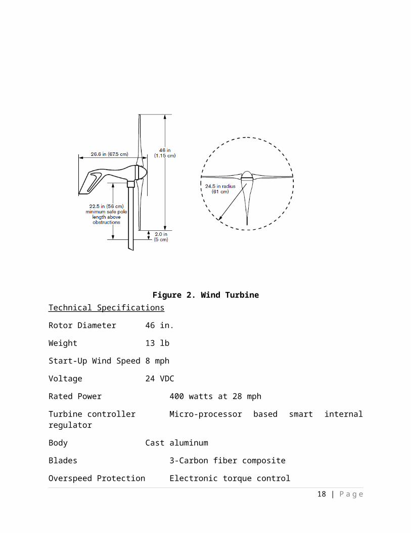
Wind TurbineThe previous team chose to purchase a wind turbine made for this type of application. The wind turbine is an Air X 400 W unit. Our team has been in discussion with the advisor concerning the selection of a different turbine to increase the practical use of the project as a whole. Several different turbines have been found, ranging in output from 1kW to 1.5 kW. As the project continues, a different turbine may be purchased and installed using the same design criteria used for the current turbine.The Air X 400 unit is designed primarily as a means to charge a battery bank which may be used to power electrical devices. This project wishes to use it as a grid-connectable power source. This means there are features of the turbine that are useful, but several that can be seen as detrimental to our design project:Battery Bank RequirementThe turbine requires a battery bank to function. This is not entirely undesired but may be an issue. Instead of power being directly used from the turbine, it is supplemented by the battery bank which is charged by the turbine. Regulation ModeThe turbine can sense the voltage level of the battery bank. When this voltage level is to high (the batter bank is fully charged), the turbine enters a regulation mode. This mode cuts the output of the turbine until the voltage of the battery bank reaches a lower level. This is undesirable, given that we wish to make use of the wind whenever is available, not just when the battery bank needs charging. Thankfully, this mode can effectively be turned off my manually setting the voltage at which the turbine enters regulation mode to one that is so high that there is no concern that it will be reached. This is done by using a DC power supply connected to the leads of the turbine and turning a potentiometer on the casing.ControllabilityThe controls that allow the turbine to function, such as the voltage regulation system, reside inside the casing. This removes the ability to control certain aspects of the turbine that may be useful to the project. The casing cannot be opened and details or schematic of the controls cannot be obtained from the manufacturer.
13 | P a g e

Figure 2. Wind TurbineTechnical SpecificationsRotor Diameter 46 in.Weight 13 lbStart-Up Wind Speed 8 mphVoltage 24 VDCRated Power 400 watts at 28 mphTurbine controller Micro-processor based smart internal regulatorBody Cast aluminumBlades 3-Carbon fiber compositeOverspeed Protection Electronic torque controlKilowatt Hours/Month 38 kWh/mo at 12 mphSurvival Wind Speed 110 mphTable 1. Wind Turbine Specifications
14 | P a g e

InterfaceThe user interface to be designed involves a PC based system where a user will be able to view the power output, speed, voltage, and current of the turbine. The previous team has designed measuring devices for the turbine along with a Labview interface that is partially finished. Our team will have to either finish this design or begin from scratch. A means of measuring the RPM of the turbine will be implemented by our team as well.The following is a high level diagram of the interface system. The transmission system of the rpm sensor has yet to be determined, but will most likely be
wireless in nature.
15 | P a g e

Figure 3. Interface Diagram
ControlsThe previous team designed a charge controller for the wind turbine system. The controller trips a relay on the other side of the inverter when the battery voltage reaches too low of a level. Our team will be left with this controller to finish testing and implement it when the turbine is installed. The controller is designed using a comparator to check the voltage of the batteries.
16 | P a g e

InverterThe previous team purchased a single-phase 2500 VA grid-tie inverter to be used in the wind turbine system. The inverter chosen is an Outback GTFX2500. This inverter will be used to transform the DC power from the wind turbine to useable 120 VAC power to connect with the grid at Coover Hall or a standalone load within Coover Hall. It is important to note that this is a hybrid inverter that is capable of both these scenarios. Many inverters are strictly on or off grid.
Technical SpecificationsNominal DC Input 24 VDCContinuous Power Rating 2500 VAAC Voltage/Frequency 120 VAC 60 Hz
17 | P a g e
Continuous AC RMS Output 20.8 Amps ACIdle Power 6-20 WattsTypical Efficiency 92%Total Harmonic Distortion 2-5%Output Voltage Regulation ± 2%Maximum Output Voltage 50 amps AC RMSAC Overload Capability Surge 6000 VA
5 seconds 4800 VA30 minutes 3200 VA
AC Input Current Max 60 amps ACAC Input Voltage/Frequency 80-150 VAC 58-62 HzDC Input Range 21-34 VDCWeight 56 lbsTable 2. Inverter Specifications
InstallationInstallation of the system has been an issue since the beginning of the project. Several problems have arisen and solutions are still being found. Most of the installation will be done by Iowa State University Facilities Department, with assistance from design team and advisor.
Wind Turbine Installation
Here is a more detailed sketch of the turbine and battery bank system provided by the manufacturer of the wind turbine. This sketch does not include the controls, measuring devices, or inverter; but still supplies a more in depth perspective on the components used to create the system.
The Stop Switch in the diagram is used to short the leads of the turbine, which effectively turns off the turbine. This is a feature unique to the Air X 400 unit and may need to be changed if turbines are replaced.
18 | P a g e

The turbine will be mounted against a wall of Coover Hall outside. It requires a pole along with proper mounting hardware. Conduit and wiring will be run on the roof and to a room inside the building that has yet to be determined.
Figure 4. Installation Schematic
Inverter Installation
The inverter will be installed inside Coover Hall in a lab that will be determined later. The inverter will then either be connected to either a single-phase gird connection or to a stand-alone load used for testing, research, and demonstration.
Controller Installation
The controllers must be placed carefully given their sensitivity to environmental conditions. The previous team will be responsible for ensuring the devices are in proper working order and installation guidelines are given.
19 | P a g e

TestingTesting of much of the equipment already purchased has been completed, but further testing will be needed as the project is extended and implemented in its’ final form. Testing of the controllers has been left to the previous team, given that they were the ones who designed them. Our team has assisted with the testing of the turbine, batteries, and inverter.
To simulate the wind that would generally spin the turbine, a coupling was fabricated that allows a power drill to be connected to the rotor assembly of the turbine. The full range of the turbine has yet to be completely tested and documented, but operation of the turbine has been verified. The battery and inverter setup has been tested under load to verify its’ operation as well.
20 | P a g e

Further testing will include plotting the full range of the turbine using the drill coupling and an rpm sensor, as well as connecting various loads to the entire system and doing more in depth tests.
Our team also assisted the previous team in preparing the turbine system for demonstration.
21 | P a g e

Resources and Schedules
Original Personal Effort Requirements
Brandon
Janssen
Luke Lehman
Kenny Thelen
Hassan Burawi
Elsammani
Ahmed
Project Reporting 15 10 15 10 10Problem Definition 10 10 10 10 10Project Design 50 50 50 50 50
Task 1-Standalone
10 10 10 10 10
Task 2-Grid 10 10 10 10 10Task 3- Test-bed 20 20 20 20 20Task 4- Testing 20 25 20 25 25Task 5- Matlab 20 20 20 20 20
Documentation 10 10 10 10 10
Totals 165 165 165 165 165
Revised Personal Effort Requirements
Brandon
Janssen
Luke Lehman
Kenny Thelen
Hassan Burawi
Elsammani
Ahmed
Project Reporting 13 15 10 15 10Problem Definition
12 14 15 10 10
Project Design 31 27 20 26 25
Task 1-Standalone
12 16 18 17 14
Task 2- Testing 20 30 13 25 20Task 3- Matlab 22 15 12 20 21
DocumentationWeb Design
200
180
1415
160
190
22 | P a g e

Totals 128 135 117 129 119Table 3. Hours
23 | P a g e

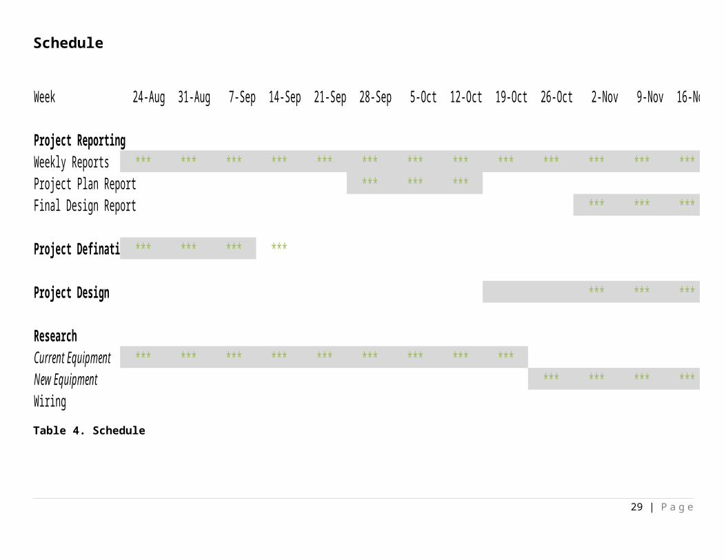
Schedule
Week 24-Aug 31-Aug 7-Sep 14-Sep 21-Sep 28-Sep 5-Oct 12-Oct 19-Oct 26-Oct 2-Nov 9-Nov 16-Nov 23-Nov 30-Nov
Project ReportingWeekly Reports *** *** *** *** *** *** *** *** *** *** *** *** *** *** ***Project Plan Report *** *** ***Final Design Report *** *** *** *** ***
Project Defination *** *** *** ***
Project Design *** *** *** ***
ResearchCurrent Equipment *** *** *** *** *** *** *** *** ***New Equipment *** *** *** *** *** ***Wiring *** ***Table 4. Schedule
24 | P a g e

The original personal efforts requirements showed the time assumed the different tasks would consume to be accomplished, however throughout the semester, the direction of the project changed numerous times mostly due to technical difficulties. The table under original personal requirements shows the intended tasks and the estimated time it would take for the tasks to be accomplished where the table under revised personal effort requirements displays the tasks accomplished and the actual time taken to complete the tasks.
Revised Project Costs Estimates
Item Estimated Cost
Air X 400 W Wind Turbine $750
Outback GTFX2524 Inverter $1800
Batteries $750
Microcontroller $25
Controller wiring and misc $20
Turbine Mounting Materials $250
Thick Gauge Wiring $175
Sensors $100
Insulated Ring Tung Terminations $10
Conduit
Labor
$100
628 Hours
Estimated Total
Table 4. Costs
$3980
25 | P a g e

Revised Original Project Costs Estimates
The project costs are similar to the previous group’s costs due to this project being an ongoing project. The costs of the project consist mainly of the turbine and its parts. However, one of the turns this project took was finding a different turbine able to generate more than 400 W. The cost of the current turbine and the generating ability is quite low proportionally to the cost it would take to mount the turbine to the building, which is estimated at $10,000. For a wind turbine with a higher generating capability, the estimated additional cost would be $5,000.
26 | P a g e

Summary
Wind power maybe the wave of the future. This wind power project will help subsides the power delivered to Coover and the understanding of current and future students. The turban will help the image of Iowa State University by showing the initiative of pursuing renewable resources.
27 | P a g e

Team MembersBrandon Janssen Luke Lehman Kenny Thelen
225 N Hyland Ave Unit 32 227 Raphael Ave Unit 21 620 S 4th St Unit 106Ames, IA 50014 Ames, IA 50014 Ames, IA 50010
712-461-0890 515-451-5014 515-451-5439
[email protected] [email protected] [email protected]
Hassan Burawi Elsammani Ahmed
153 N Hyland Ave Unit 2 2901 Delaware Ave #4Ames, IA 50014 Ames, Iowa 50014
515-441-2923 319-491-7577
[email protected] [email protected]
Group Email: [email protected]
Advisor
Dr. Venkataramana Ajjarapu
Office: 1122 CooverAmes, IA 50011-3060
515-294-7687515-294-4263 fax
Home: 2704 Valley View RdAmes, IA 50014-4500
515-292-3887
Email: [email protected]
28 | P a g e
References
http://www.windenergy.com/products/air_x.htm
http://www.outbackpower.com/products/sinewave_inverter/grid_tie/
29 | P a g e