exercise 1: series rlc circuits - lab-volt · t) in a series rlc circuit is a combination of the...
TRANSCRIPT
Student Manual
10 FACET by Lab-Volt
RLC Circuits AC 2 Fundamentals
Exercise 1: Series RLC Circuits
EXERCISE OBJECTIVE
When you have completed this exercise, you will be able to analyze series RLC circuits by using
calculations and measurements. You will verify your results with an oscilloscope.
DISCUSSION
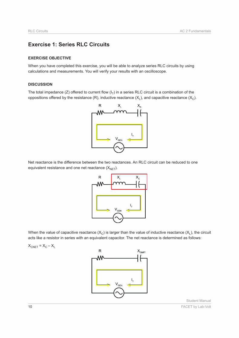
T) in a series RLC circuit is a combination of the
oppositions offered by the resistance (R), inductive reactance (XL), and capacitive reactance (XC).
Net reactance is the difference between the two reactances. An RLC circuit can be reduced to one
equivalent resistance and one net reactance (XNET).
When the value of capacitive reactance (XC) is larger than the value of inductive reactance (XL), the circuit
acts like a resistor in series with an equivalent capacitor. The net reactance is determined as follows:
XCNET = XC – XL
Student Manual
FACET by Lab-Volt 11
AC 2 Fundamentals RLC Circuits
However, when the value of inductive reactance (XL) is larger than the capacitive reactance (XC), the
circuit acts like a resistor in series with an equivalent inductor. The net reactance is determined as follows:
XLNET = XL – XC
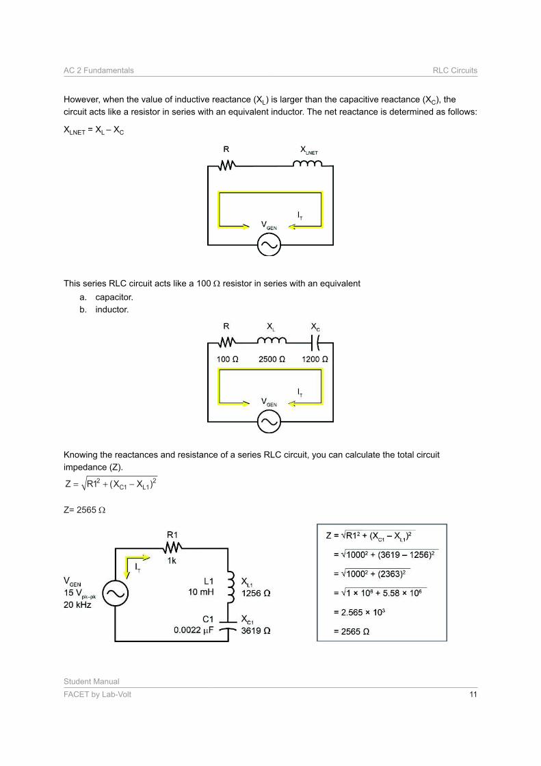
This series RLC circuit acts like a 100 resistor in series with an equivalent
a. capacitor.
b. inductor.
Knowing the reactances and resistance of a series RLC circuit, you can calculate the total circuit
impedance (Z).
Z R X XC L= + −12 1 12( )
Z= 2565

Student Manual
12 FACET by Lab-Volt
RLC Circuits AC 2 Fundamentals
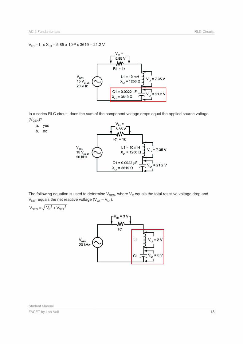
Using the values of Z and VGEN, you can calculate the total circuit current from Ohm’s law.
Now that you know circuit current, you can calculate the voltage drop across each component by using
Ohm’s law.
VR1 = IT x R1 = 5.85 x 10–3 x 1000 = 5.85 V
VL1 = IT x XL1 = 5.85 x 10–3 x 1256 = 7.35 V
Student Manual
FACET by Lab-Volt 13
AC 2 Fundamentals RLC Circuits
VC1 = IT x XC1 = 5.85 x 10–3 x 3619 = 21.2 V
In a series RLC circuit, does the sum of the component voltage drops equal the applied source voltage
(VGEN)?
a. yes
b. no
The following equation is used to determine VGEN, where VR equals the total resistive voltage drop and
VNET equals the net reactive voltage (VC1 – VL1).
2 2GEN R NETV V V= +

Student Manual
14 FACET by Lab-Volt
RLC Circuits AC 2 Fundamentals
Calculate VGEN.
( )22
GEN R1 C1 L1V V V V= + −
VGEN= Vpk-pk (Recall Value 1)
This phasor diagram shows the relationship of the voltage drops of the resistive and reactive components
to the source voltage (VGEN).
VGEN does not equal the sum of the voltage drops across the individual components.
( )22
GEN R1 C1 L1V V V V= + −
Student Manual
FACET by Lab-Volt 15
AC 2 Fundamentals RLC Circuits
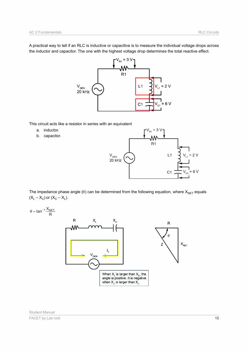
A practical way to tell if an RLC is inductive or capacitive is to measure the individual voltage drops across
the inductor and capacitor. The one with the highest voltage drop determines the total reactive effect.
This circuit acts like a resistor in series with an equivalent
a. inductor.
b. capacitor.
The impedance phase angle ( ) can be determined from the following equation, where XNET equals
(XL – XC) or (XC – XL).
1 NETXtan
R
−θ =
Student Manual
16 FACET by Lab-Volt
RLC Circuits AC 2 Fundamentals
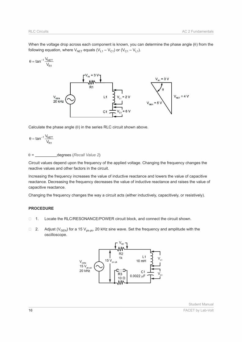
When the voltage drop across each component is known, you can determine the phase angle ( ) from the
following equation, where VNET equals (VL1 – VC1) or (VC1 – VL1).
1 NET
R1
Vtan
V
−θ =
Calculate the phase angle ( ) in the series RLC circuit shown above.
1 NET
R1
Vtan
V
−θ =
= degrees (Recall Value 2)
Circuit values depend upon the frequency of the applied voltage. Changing the frequency changes the
reactive values and other factors in the circuit.
Increasing the frequency increases the value of inductive reactance and lowers the value of capacitive
reactance. Decreasing the frequency decreases the value of inductive reactance and raises the value of
capacitive reactance.
Changing the frequency changes the way a circuit acts (either inductively, capacitively, or resistively).
PROCEDURE
Adjust (VGEN) for a 15 Vpk-pk, 20 kHz sine wave. Set the frequency and amplitude with the
oscilloscope.
Student Manual
FACET by Lab-Volt 17
AC 2 Fundamentals RLC Circuits
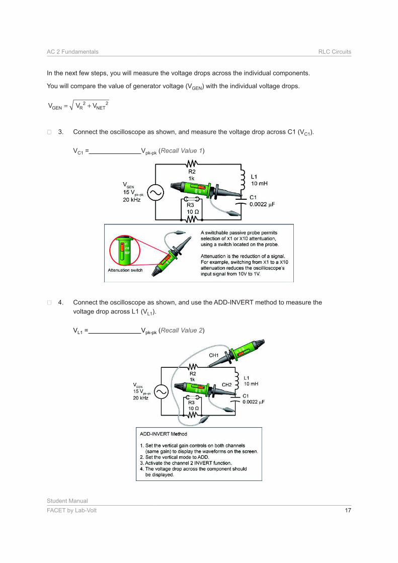
In the next few steps, you will measure the voltage drops across the individual components.
You will compare the value of generator voltage (VGEN) with the individual voltage drops.
2 2GEN R NETV V V= +
Connect the oscilloscope as shown, and measure the voltage drop across C1 (VC1).
VC1 = Vpk-pk (Recall Value 1)
Connect the oscilloscope as shown, and use the ADD-INVERT method to measure the
voltage drop across L1 (VL1).
VL1 = Vpk-pk (Recall Value 2)
Student Manual
18 FACET by Lab-Volt
RLC Circuits AC 2 Fundamentals
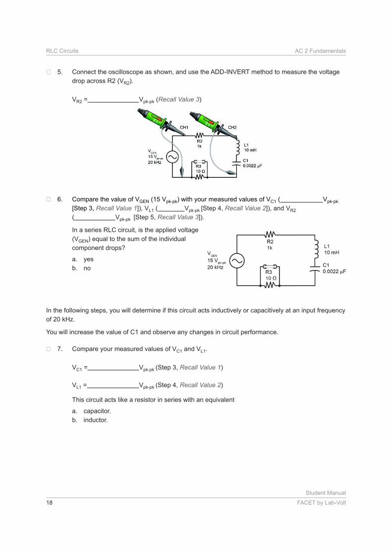
Connect the oscilloscope as shown, and use the ADD-INVERT method to measure the voltage
drop across R2 (VR2).
VR2 = Vpk-pk (Recall Value 3)
Compare the value of VGEN (15 Vpk-pk) with your measured values of VC1 ( Vpk-pk
[Step 3, Recall Value 1]), VL1 ( Vpk-pk [Step 4, Recall Value 2]), and VR2
( Vpk-pk [Step 5, Recall Value 3]).
In a series RLC circuit, is the applied voltage
(VGEN) equal to the sum of the individual
component drops?
a. yes
b. no
In the following steps, you will determine if this circuit acts inductively or capacitively at an input frequency
of 20 kHz.
You will increase the value of C1 and observe any changes in circuit performance.
Compare your measured values of VC1 and VL1.
VC1 = Vpk-pk (Step 3, Recall Value 1)
VL1 = Vpk-pk (Step 4, Recall Value 2)
This circuit acts like a resistor in series with an equivalent
a. capacitor.
b. inductor.
Student Manual
FACET by Lab-Volt 19
AC 2 Fundamentals RLC Circuits
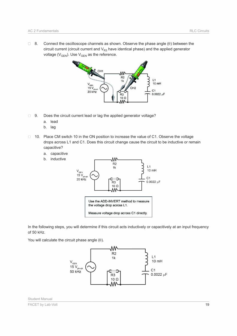
Connect the oscilloscope channels as shown. Observe the phase angle ( ) between the
circuit current (circuit current and VR3 have identical phase) and the applied generator
voltage (VGEN). Use VGEN as the reference.
Does the circuit current lead or lag the applied generator voltage?
a. lead
b. lag
Place CM switch 10 in the ON position to increase the value of C1. Observe the voltage
drops across L1 and C1. Does this circuit change cause the circuit to be inductive or remain
capacitive?
a. capacitive
b. inductive
In the following steps, you will determine if this circuit acts inductively or capacitively at an input frequency
of 50 kHz.
You will calculate the circuit phase angle ( ).
Student Manual
20 FACET by Lab-Volt
RLC Circuits AC 2 Fundamentals
Adjust VGEN for a 15 Vpk-pk, 50 kHz sine wave. Set the frequency and amplitude with the
oscilloscope.
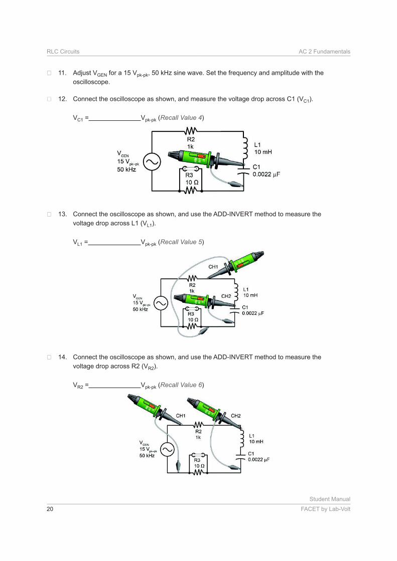
Connect the oscilloscope as shown, and measure the voltage drop across C1 (VC1).
VC1 = Vpk-pk (Recall Value 4)
Connect the oscilloscope as shown, and use the ADD-INVERT method to measure the
voltage drop across L1 (VL1).
VL1 = Vpk-pk (Recall Value 5)
Connect the oscilloscope as shown, and use the ADD-INVERT method to measure the
voltage drop across R2 (VR2).
VR2 = Vpk-pk (Recall Value 6)
Student Manual
FACET by Lab-Volt 21
AC 2 Fundamentals RLC Circuits
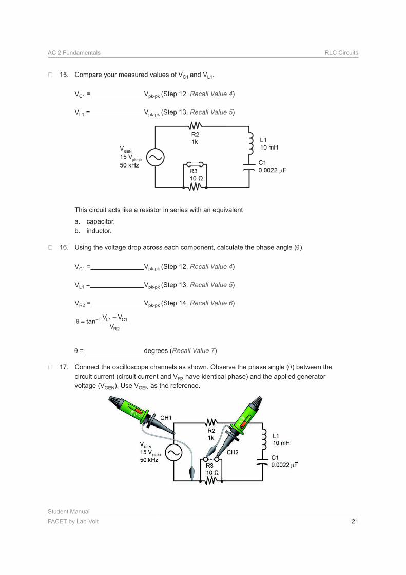
Compare your measured values of VC1 and VL1.
VC1 = Vpk-pk (Step 12, Recall Value 4)
VL1 = Vpk-pk (Step 13, Recall Value 5)
This circuit acts like a resistor in series with an equivalent
a. capacitor.
b. inductor.
Using the voltage drop across each component, calculate the phase angle ( ).
VC1 = Vpk-pk (Step 12, Recall Value 4)
VL1 = Vpk-pk (Step 13, Recall Value 5)
VR2 = Vpk-pk (Step 14, Recall Value 6)
− −θ =
1 L1 C1
R2
V Vtan
V
= degrees (Recall Value 7)
Connect the oscilloscope channels as shown. Observe the phase angle ( ) between the
circuit current (circuit current and VR3 have identical phase) and the applied generator
voltage (VGEN). Use VGEN as the reference.
Student Manual
22 FACET by Lab-Volt
RLC Circuits AC 2 Fundamentals
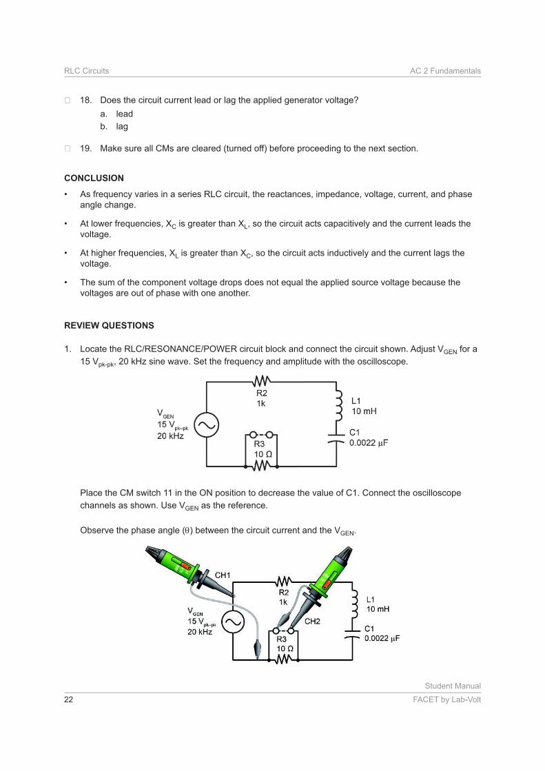
Does the circuit current lead or lag the applied generator voltage?
a. lead
b. lag
Make sure all CMs are cleared (turned off) before proceeding to the next section.
CONCLUSION
• As frequency varies in a series RLC circuit, the reactances, impedance, voltage, current, and phase
angle change.
• At lower frequencies, XC is greater than XL, so the circuit acts capacitively and the current leads the
voltage.
• At higher frequencies, XL is greater than XC, so the circuit acts inductively and the current lags the
voltage.
• The sum of the component voltage drops does not equal the applied source voltage because the
voltages are out of phase with one another.
REVIEW QUESTIONS
1. GEN for a
15 Vpk-pk, 20 kHz sine wave. Set the frequency and amplitude with the oscilloscope.
Place the CM switch 11 in the ON position to decrease the value of C1. Connect the oscilloscope
channels as shown. Use VGEN as the reference.
Observe the phase angle ( ) between the circuit current and the VGEN.
Student Manual
FACET by Lab-Volt 23
AC 2 Fundamentals RLC Circuits
While observing the phase angle ( ), toggle CM switch 11 off and on.
Based on your observation of the phase angle ( ), you determine that the CM caused the circuit to
a. change from capacitive to inductive.
b. remain inductive.
c. change from inductive to capacitive.
d. remain capacitive.
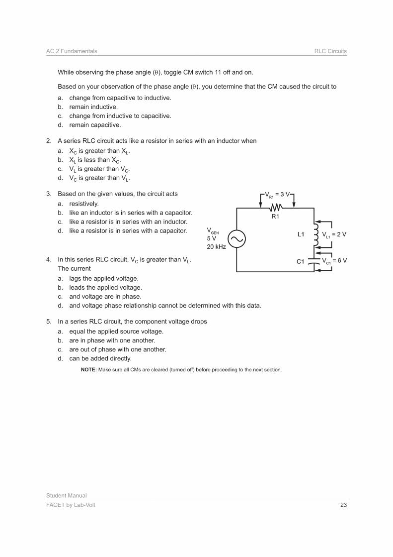
2. A series RLC circuit acts like a resistor in series with an inductor when
a. XC is greater than XL.
b. XL is less than XC.
c. VL is greater than VC.
d. VC is greater than VL.
3. Based on the given values, the circuit acts
a. resistively.
b. like an inductor is in series with a capacitor.
c. like a resistor is in series with an inductor.
d. like a resistor is in series with a capacitor.
4. In this series RLC circuit, VC is greater than VL.
The current
a. lags the applied voltage.
b. leads the applied voltage.
c. and voltage are in phase.
d. and voltage phase relationship cannot be determined with this data.
5. In a series RLC circuit, the component voltage drops
a. equal the applied source voltage.
b. are in phase with one another.
c. are out of phase with one another.
d. can be added directly.
NOTE: Make sure all CMs are cleared (turned off) before proceeding to the next section.