exergy: a measure of work potential · 8–1 exergy: work potential of energy when a new energy...
TRANSCRIPT

Chapter 8EXERGY: A MEASURE OF WORK POTENTIAL
| 423
The increased awareness that the world’s energy
resources are limited has caused many countries to
reexamine their energy policies and take drastic mea-
sures in eliminating waste. It has also sparked interest in the
scientific community to take a closer look at the energy con-
version devices and to develop new techniques to better utilize
the existing limited resources. The first law of thermodynamics
deals with the quantity of energy and asserts that energy can-
not be created or destroyed. This law merely serves as a nec-
essary tool for the bookkeeping of energy during a process
and offers no challenges to the engineer. The second law,
however, deals with the quality of energy. More specifically, it
is concerned with the degradation of energy during a process,
the entropy generation, and the lost opportunities to do work;
and it offers plenty of room for improvement.
The second law of thermodynamics has proved to be a
very powerful tool in the optimization of complex thermody-
namic systems. In this chapter, we examine the performance
of engineering devices in light of the second law of thermody-
namics. We start our discussions with the introduction of
exergy (also called availability), which is the maximum useful
work that could be obtained from the system at a given state
in a specified environment, and we continue with the reversi-
ble work, which is the maximum useful work that can be
obtained as a system undergoes a process between two
specified states. Next we discuss the irreversibility (also called
the exergy destruction or lost work), which is the wasted work
potential during a process as a result of irreversibilities, and
we define a second-law efficiency. We then develop the exergy
balance relation and apply it to closed systems and control
volumes.
Objectives
The objectives of Chapter 8 are to:
• Examine the performance of engineering devices in light of
the second law of thermodynamics.
• Define exergy, which is the maximum useful work that
could be obtained from the system at a given state in a
specified environment.
• Define reversible work, which is the maximum useful work
that can be obtained as a system undergoes a process
between two specified states.
• Define the exergy destruction, which is the wasted work
potential during a process as a result of irreversibilities.
• Define the second-law efficiency.
• Develop the exergy balance relation.
• Apply exergy balance to closed systems and control
volumes.

8–1 ■ EXERGY: WORK POTENTIAL OF ENERGY
When a new energy source, such as a geothermal well, is discovered, thefirst thing the explorers do is estimate the amount of energy contained in thesource. This information alone, however, is of little value in decidingwhether to build a power plant on that site. What we really need to know isthe work potential of the source—that is, the amount of energy we canextract as useful work. The rest of the energy is eventually discarded aswaste energy and is not worthy of our consideration. Thus, it would be verydesirable to have a property to enable us to determine the useful workpotential of a given amount of energy at some specified state. This propertyis exergy, which is also called the availability or available energy.
The work potential of the energy contained in a system at a specified stateis simply the maximum useful work that can be obtained from the system.You will recall that the work done during a process depends on the initialstate, the final state, and the process path. That is,
In an exergy analysis, the initial state is specified, and thus it is not a vari-able. The work output is maximized when the process between two specifiedstates is executed in a reversible manner, as shown in Chap. 7. Therefore, allthe irreversibilities are disregarded in determining the work potential.Finally, the system must be in the dead state at the end of the process tomaximize the work output.
A system is said to be in the dead state when it is in thermodynamic equi-librium with the environment it is in (Fig. 8–1). At the dead state, a system isat the temperature and pressure of its environment (in thermal and mechanicalequilibrium); it has no kinetic or potential energy relative to the environment(zero velocity and zero elevation above a reference level); and it does notreact with the environment (chemically inert). Also, there are no unbalancedmagnetic, electrical, and surface tension effects between the system and itssurroundings, if these are relevant to the situation at hand. The properties ofa system at the dead state are denoted by subscript zero, for example, P0, T0,h0, u0, and s0. Unless specified otherwise, the dead-state temperature andpressure are taken to be T0 � 25°C (77°F) and P0 � 1 atm (101.325 kPa or14.7 psia). A system has zero exergy at the dead state (Fig. 8–2).
Distinction should be made between the surroundings, immediate sur-
roundings, and the environment. By definition, surroundings are everythingoutside the system boundaries. The immediate surroundings refer to theportion of the surroundings that is affected by the process, and environment
refers to the region beyond the immediate surroundings whose propertiesare not affected by the process at any point. Therefore, any irreversibilitiesduring a process occur within the system and its immediate surroundings,and the environment is free of any irreversibilities. When analyzing thecooling of a hot baked potato in a room at 25°C, for example, the warm airthat surrounds the potato is the immediate surroundings, and the remainingpart of the room air at 25°C is the environment. Note that the temperature ofthe immediate surroundings changes from the temperature of the potato atthe boundary to the environment temperature of 25°C (Fig. 8–3).
Work � f 1initial state, process path, final state 2
424 | Thermodynamics
AIR
25°C
101 kPa
V = 0
z = 0
T0 = 25°C
P0 = 101 kPa
FIGURE 8–1
A system that is in equilibrium with itsenvironment is said to be at the deadstate.
FIGURE 8–2
At the dead state, the useful workpotential (exergy) of a system is zero.
© Reprinted with special permission of King
Features Syndicate.
SEE TUTORIAL CH. 8, SEC. 1 ON THE DVD.
INTERACTIVE
TUTORIAL

The notion that a system must go to the dead state at the end of theprocess to maximize the work output can be explained as follows: If thesystem temperature at the final state is greater than (or less than) the tem-perature of the environment it is in, we can always produce additional workby running a heat engine between these two temperature levels. If the finalpressure is greater than (or less than) the pressure of the environment, wecan still obtain work by letting the system expand to the pressure of theenvironment. If the final velocity of the system is not zero, we can catchthat extra kinetic energy by a turbine and convert it to rotating shaft work,and so on. No work can be produced from a system that is initially at thedead state. The atmosphere around us contains a tremendous amount ofenergy. However, the atmosphere is in the dead state, and the energy it con-tains has no work potential (Fig. 8–4).
Therefore, we conclude that a system delivers the maximum possible work
as it undergoes a reversible process from the specified initial state to the
state of its environment, that is, the dead state. This represents the useful
work potential of the system at the specified state and is called exergy. It isimportant to realize that exergy does not represent the amount of work thata work-producing device will actually deliver upon installation. Rather, itrepresents the upper limit on the amount of work a device can deliver with-
out violating any thermodynamic laws. There will always be a difference,large or small, between exergy and the actual work delivered by a device.This difference represents the room engineers have for improvement.
Note that the exergy of a system at a specified state depends on the condi-tions of the environment (the dead state) as well as the properties of the sys-tem. Therefore, exergy is a property of the system–environment combination
and not of the system alone. Altering the environment is another way ofincreasing exergy, but it is definitely not an easy alternative.
The term availability was made popular in the United States by the M.I.T.School of Engineering in the 1940s. Today, an equivalent term, exergy,
introduced in Europe in the 1950s, has found global acceptance partlybecause it is shorter, it rhymes with energy and entropy, and it can beadapted without requiring translation. In this text the preferred term isexergy.
Exergy (Work Potential) Associatedwith Kinetic and Potential EnergyKinetic energy is a form of mechanical energy, and thus it can be convertedto work entirely. Therefore, the work potential or exergy of the kinetic energyof a system is equal to the kinetic energy itself regardless of the temperatureand pressure of the environment. That is,
Exergy of kinetic energy: (8–1)
where V is the velocity of the system relative to the environment.
xke � ke �V 2
2ÉÉ1kJ>kg 2
Chapter 8 | 425
HOT
POTATO70°C
25°C
25°C
Environment
Immediate
surroundings
FIGURE 8–3
The immediate surroundings of a hotpotato are simply the temperaturegradient zone of the air next to thepotato.
FIGURE 8–4
The atmosphere contains atremendous amount of energy, butno exergy.
© Vol. 74/PhotoDisc

Potential energy is also a form of mechanical energy, and thus it can beconverted to work entirely. Therefore, the exergy of the potential energy of asystem is equal to the potential energy itself regardless of the temperatureand pressure of the environment (Fig. 8–5). That is,
Exergy of potential energy: (8–2)
where g is the gravitational acceleration and z is the elevation of the systemrelative to a reference level in the environment.
Therefore, the exergies of kinetic and potential energies are equal to them-selves, and they are entirely available for work. However, the internal energy uand enthalpy h of a system are not entirely available for work, as shown later.
xpe � pe � gzÉÉ1kJ>kg 2
426 | Thermodynamics
m
Wmax = mgz
z
⋅
⋅ ⋅
FIGURE 8–5
The work potential or exergy ofpotential energy is equal to thepotential energy itself.
EXAMPLE 8–1 Maximum Power Generation by a Wind Turbine
A wind turbine with a 12-m-diameter rotor, as shown in Fig. 8–6, is to be
installed at a location where the wind is blowing steadily at an average veloc-
ity of 10 m/s. Determine the maximum power that can be generated by the
wind turbine.
Solution A wind turbine is being considered for a specified location. The max-
imum power that can be generated by the wind turbine is to be determined.
Assumptions Air is at standard conditions of 1 atm and 25°C, and thus its
density is 1.18 kg/m3.
Analysis The air flowing with the wind has the same properties as the stag-
nant atmospheric air except that it possesses a velocity and thus some
kinetic energy. This air will reach the dead state when it is brought to a com-
plete stop. Therefore, the exergy of the blowing air is simply the kinetic
energy it possesses:
That is, every unit mass of air flowing at a velocity of 10 m/s has a work
potential of 0.05 kJ/kg. In other words, a perfect wind turbine will bring the
air to a complete stop and capture that 0.05 kJ/kg of work potential. To
determine the maximum power, we need to know the amount of air passing
through the rotor of the wind turbine per unit time, that is, the mass flow
rate, which is determined to be
Thus,
This is the maximum power available to the wind turbine. Assuming a con-
version efficiency of 30 percent, an actual wind turbine will convert 20.0 kW
to electricity. Notice that the work potential for this case is equal to the
entire kinetic energy of the air.
Discussion It should be noted that although the entire kinetic energy of the
wind is available for power production, Betz’s law states that the power output
of a wind machine is at maximum when the wind is slowed to one-third of its
initial velocity. Therefore, for maximum power (and thus minimum cost per
Maximum power � m# 1ke 2 � 11335 kg>s 2 10.05 kJ>kg 2 � 66.8 kW
m#
� rAV � r pD2
4 V � 11.18 kg>m3 2 p 112 m 2 2
4 110 m>s 2 � 1335 kg>s
ke �V 2
2�
110 m>s 2 22
a 1 kJ>kg
1000 m2>s2b � 0.05 kJ>kg
10 m/s
FIGURE 8–6
Schematic for Example 8–1.

8–2 ■ REVERSIBLE WORK AND IRREVERSIBILITY
The property exergy serves as a valuable tool in determining the quality ofenergy and comparing the work potentials of different energy sources or sys-tems. The evaluation of exergy alone, however, is not sufficient for studyingengineering devices operating between two fixed states. This is because whenevaluating exergy, the final state is always assumed to be the dead state,
which is hardly ever the case for actual engineering systems. The isentropicefficiencies discussed in Chap. 7 are also of limited use because the exit state
Chapter 8 | 427
installed power), the highest efficiency of a wind turbine is about 59 percent.
In practice, the actual efficiency ranges between 20 and 40 percent and is
about 35 percent for many wind turbines.
Wind power is suitable for harvesting when there are steady winds with an
average velocity of at least 6 m/s (or 13 mph). Recent improvements in
wind turbine design have brought the cost of generating wind power to
about 5 cents per kWh, which is competitive with electricity generated from
other resources.
EXAMPLE 8–2 Exergy Transfer from a Furnace
Consider a large furnace that can transfer heat at a temperature of 2000 R
at a steady rate of 3000 Btu/s. Determine the rate of exergy flow associated
with this heat transfer. Assume an environment temperature of 77°F.
Solution Heat is being supplied by a large furnace at a specified tempera-
ture. The rate of exergy flow is to be determined.
Analysis The furnace in this example can be modeled as a heat reservoir
that supplies heat indefinitely at a constant temperature. The exergy of this
heat energy is its useful work potential, that is, the maximum possible
amount of work that can be extracted from it. This corresponds to the
amount of work that a reversible heat engine operating between the furnace
and the environment can produce.
The thermal efficiency of this reversible heat engine is
That is, a heat engine can convert, at best, 73.2 percent of the heat received
from this furnace to work. Thus, the exergy of this furnace is equivalent to
the power produced by the reversible heat engine:
Discussion Notice that 26.8 percent of the heat transferred from the fur-
nace is not available for doing work. The portion of energy that cannot be
converted to work is called unavailable energy (Fig. 8–7). Unavailable energy
is simply the difference between the total energy of a system at a specified
state and the exergy of that energy.
W#
max � W#rev � hth,rev Q
#in � 10.732 2 13000 Btu>s 2 � 2196 Btu/s
hth,max � hth,rev � 1 �TL
TH
� 1 �T0
TH
� 1 �537 R
2000 R� 0.732 1or 73.2% 2
Totalenergy
Exergy
Unavailableenergy
FIGURE 8–7
Unavailable energy is the portion ofenergy that cannot be converted towork by even a reversible heat engine.
SEE TUTORIAL CH. 8, SEC. 2 ON THE DVD.
INTERACTIVE
TUTORIAL

of the model (isentropic) process is not the same as the actual exit state and itis limited to adiabatic processes.
In this section, we describe two quantities that are related to the actualinitial and final states of processes and serve as valuable tools in the ther-modynamic analysis of components or systems. These two quantities are thereversible work and irreversibility (or exergy destruction). But first weexamine the surroundings work, which is the work done by or against thesurroundings during a process.
The work done by work-producing devices is not always entirely in ausable form. For example, when a gas in a piston–cylinder device expands,part of the work done by the gas is used to push the atmospheric air out ofthe way of the piston (Fig. 8–8). This work, which cannot be recovered andutilized for any useful purpose, is equal to the atmospheric pressure P0
times the volume change of the system,
(8–3)
The difference between the actual work W and the surroundings work Wsurr
is called the useful work Wu:
(8–4)
When a system is expanding and doing work, part of the work done is usedto overcome the atmospheric pressure, and thus Wsurr represents a loss.When a system is compressed, however, the atmospheric pressure helps thecompression process, and thus Wsurr represents a gain.
Note that the work done by or against the atmospheric pressure has signif-icance only for systems whose volume changes during the process (i.e., sys-tems that involve moving boundary work). It has no significance for cyclicdevices and systems whose boundaries remain fixed during a process suchas rigid tanks and steady-flow devices (turbines, compressors, nozzles, heatexchangers, etc.), as shown in Fig. 8–9.
Reversible work Wrev is defined as the maximum amount of useful work
that can be produced (or the minimum work that needs to be supplied) as a
system undergoes a process between the specified initial and final states. Thisis the useful work output (or input) obtained (or expended) when the processbetween the initial and final states is executed in a totally reversible manner.When the final state is the dead state, the reversible work equals exergy. Forprocesses that require work, reversible work represents the minimum amountof work necessary to carry out that process. For convenience in presentation,the term work is used to denote both work and power throughout this chapter.
Any difference between the reversible work Wrev and the useful work Wu
is due to the irreversibilities present during the process, and this differenceis called irreversibility I. It is expressed as (Fig. 8–10)
(8–5)
The irreversibility is equivalent to the exergy destroyed, discussed in Sec.8–4. For a totally reversible process, the actual and reversible work termsare identical, and thus the irreversibility is zero. This is expected sincetotally reversible processes generate no entropy. Irreversibility is a positive
quantity for all actual (irreversible) processes since Wrev � Wu for work-producing devices and Wrev � Wu for work-consuming devices.
I � Wrev,out � Wu,outÉorÉI � Wu,in � Wrev,in
Wu � W � Wsurr � W � P0 1V2 � V1 2
Wsurr � P0 1V2 � V1 2
428 | Thermodynamics
Atmosphericair
SYSTEM
V1
P0
Atmosphericair
SYSTEM
V2
P0
FIGURE 8–8
As a closed system expands, somework needs to be done to push theatmospheric air out of the way (Wsurr).
Rigidtanks
Cyclicdevices
Steady-flowdevices
FIGURE 8–9
For constant-volume systems, the totalactual and useful works are identical(Wu � W).
Initial state
Actual processWu < Wrev
Reversible processWrev
Final state
I = Wrev – Wu
FIGURE 8–10
The difference between reversiblework and actual useful work is theirreversibility.

Irreversibility can be viewed as the wasted work potential or the lost
opportunity to do work. It represents the energy that could have been con-verted to work but was not. The smaller the irreversibility associated with aprocess, the greater the work that is produced (or the smaller the work thatis consumed). The performance of a system can be improved by minimizingthe irreversibility associated with it.
Chapter 8 | 429
EXAMPLE 8–3 The Rate of Irreversibility of a Heat Engine
A heat engine receives heat from a source at 1200 K at a rate of 500 kJ/s
and rejects the waste heat to a medium at 300 K (Fig. 8–11). The power
output of the heat engine is 180 kW. Determine the reversible power and the
irreversibility rate for this process.
Solution The operation of a heat engine is considered. The reversible power
and the irreversibility rate associated with this operation are to be determined.
Analysis The reversible power for this process is the amount of power that a
reversible heat engine, such as a Carnot heat engine, would produce when
operating between the same temperature limits, and is determined to be:
This is the maximum power that can be produced by a heat engine operating
between the specified temperature limits and receiving heat at the specified
rate. This would also represent the available power if 300 K were the lowest
temperature available for heat rejection.
The irreversibility rate is the difference between the reversible power (max-
imum power that could have been produced) and the useful power output:
Discussion Note that 195 kW of power potential is wasted during this
process as a result of irreversibilities. Also, the 500 � 375 � 125 kW of
heat rejected to the sink is not available for converting to work and thus is
not part of the irreversibility.
I#� W#
rev,out � W#u,out � 375 � 180 � 195 kW
W#
rev � hth,rev Q#
in � a 1 �Tsink
Tsource
bQ#
in � a1 �300 K
1200 Kb 1500 kW 2 � 375 kW
EXAMPLE 8–4 Irreversibility during the Cooling
of an Iron Block
A 500-kg iron block shown in Fig. 8–12 is initially at 200°C and is allowed
to cool to 27°C by transferring heat to the surrounding air at 27°C. Deter-
mine the reversible work and the irreversibility for this process.
Solution A hot iron block is allowed to cool in air. The reversible work and
irreversibility associated with this process are to be determined.
Assumptions 1 The kinetic and potential energies are negligible. 2 The
process involves no work interactions.
·
·
Sink 300 K
HE
W = 180 kW
Qin = 500 kJ/s
Source 1200 K
FIGURE 8–11
Schematic for Example 8–3.
Surrounding air
IRON
200°C27°C
T0 = 27°C
Heat
FIGURE 8–12
Schematic for Example 8–4.

430 | Thermodynamics
Analysis We take the iron block as the system. This is a closed system
since no mass crosses the system boundary. We note that heat is lost from
the system.
It probably came as a surprise to you that we are asking to find the
“reversible work” for a process that does not involve any work interactions.
Well, even if no attempt is made to produce work during this process, the
potential to do work still exists, and the reversible work is a quantitative
measure of this potential.
The reversible work in this case is determined by considering a series of
imaginary reversible heat engines operating between the source (at a variable
temperature T ) and the sink (at a constant temperature T0), as shown in
Fig. 8–13. Summing their work output:
and
The source temperature T changes from T1 � 200°C � 473 K to T0 � 27°C �
300 K during this process. A relation for the differential heat transfer from the
iron block can be obtained from the differential form of the energy balance
applied on the iron block,
Net energy transfer Change in internal, kinetic,by heat, work, and mass potential, etc., energies
Then,
since heat transfers from the iron and to the heat engine are equal in magni-
tude and opposite in direction. Substituting and performing the integration,
the reversible work is determined to be
where the specific heat value is obtained from Table A–3. The first term in
the above equation [Q � mcavg(T1 � T0) � 38,925 kJ] is the total heat
transfer from the iron block to the heat engine. The reversible work for this
problem is found to be 8191 kJ, which means that 8191 (21 percent) of the
38,925 kJ of heat transferred from the iron block to the ambient air could
have been converted to work. If the specified ambient temperature of 27°C
is the lowest available environment temperature, the reversible work deter-
mined above also represents the exergy, which is the maximum work poten-
tial of the sensible energy contained in the iron block.
� 8191 kJ
� 1500 kg 2 10.45 kJ>kg # K 2 c 1473 � 300 2 K � 1300 K 2 ln
473 K
300 Kd
Wrev � �T0
T1
a1 �T0
Tb 1�mcavg dT 2 � mcavg 1T1 � T0 2 � mcavg T0 ln
T1
T0
dQ in,heat engine � dQ out,system � �mcavg dT
�dQ out � dU � mcavg dT
dE in � dEoutÉ�ÉÉdE system
Wrev � � a1 �T0
Tb dQin
dWrev � hth,rev dQ in � a1 �
Tsink
Tsource
b dQ in � a 1 �T0
Tb dQ in
Surroundings
27°C
Rev.
HE
Qin
Wrev
IRON
200°C27°C
FIGURE 8–13
An irreversible heat transfer processcan be made reversible by the use of areversible heat engine.

Chapter 8 | 431
The irreversibility for this process is determined from its definition,
Discussion Notice that the reversible work and irreversibility (the wasted
work potential) are the same for this case since the entire work potential is
wasted. The source of irreversibility in this process is the heat transfer
through a finite temperature difference.
I � Wrev � Wu � 8191 � 0 � 8191 kJ
EXAMPLE 8–5 Heating Potential of a Hot Iron Block
The iron block discussed in Example 8–4 is to be used to maintain a house
at 27°C when the outdoor temperature is 5°C. Determine the maximum
amount of heat that can be supplied to the house as the iron cools to 27°C.
Solution The iron block is now reconsidered for heating a house. The max-
imum amount of heating this block can provide is to be determined.
Analysis Probably the first thought that comes to mind to make the most
use of the energy stored in the iron block is to take it inside and let it cool
in the house, as shown in Fig. 8–14, transferring its sensible energy as
heat to the indoors air (provided that it meets the approval of the house-
hold, of course). The iron block can keep “losing” heat until its tempera-
ture drops to the indoor temperature of 27°C, transferring a total of
38,925 kJ of heat. Since we utilized the entire energy of the iron block
available for heating without wasting a single kilojoule, it seems like we
have a 100-percent-efficient operation, and nothing can beat this, right?
Well, not quite.
In Example 8–4 we determined that this process has an irreversibility of
8191 kJ, which implies that things are not as “perfect” as they seem.
A “perfect” process is one that involves “zero” irreversibility. The irreversibil-
ity in this process is associated with the heat transfer through a finite tem-
perature difference that can be eliminated by running a reversible heat
engine between the iron block and the indoor air. This heat engine produces
(as determined in Example 8–4) 8191 kJ of work and reject the remaining
38,925 � 8191 � 30,734 kJ of heat to the house. Now we managed to
eliminate the irreversibility and ended up with 8191 kJ of work. What can
we do with this work? Well, at worst we can convert it to heat by running a
paddle wheel, for example, creating an equal amount of irreversibility. Or we
can supply this work to a heat pump that transports heat from the outdoors
at 5°C to the indoors at 27°C. Such a heat pump, if reversible, has a coeffi-
cient of performance of
That is, this heat pump can supply the house with 13.6 times the energy it
consumes as work. In our case, it will consume the 8191 kJ of work and
deliver 8191 � 13.6 � 111,398 kJ of heat to the house. Therefore, the hot
iron block has the potential to supply130,734 � 111,398 2 kJ � 142,132 kJ � 142 MJ
COPHP �1
1 � TL >TH
�1
1 � 1278 K 2 > 1300 K 2 � 13.6
5°C
27°C
IronIron200200°C
Heat
FIGURE 8–14
Schematic for Example 8–5.

8–3 ■ SECOND-LAW EFFICIENCY, hII
In Chap. 6 we defined the thermal efficiency and the coefficient of perfor-
mance for devices as a measure of their performance. They are defined onthe basis of the first law only, and they are sometimes referred to as thefirst-law efficiencies. The first law efficiency, however, makes no referenceto the best possible performance, and thus it may be misleading.
Consider two heat engines, both having a thermal efficiency of 30 per-cent, as shown in Fig. 8–15. One of the engines (engine A) is supplied withheat from a source at 600 K, and the other one (engine B) from a source at1000 K. Both engines reject heat to a medium at 300 K. At first glance, bothengines seem to convert to work the same fraction of heat that they receive;thus they are performing equally well. When we take a second look at theseengines in light of the second law of thermodynamics, however, we see atotally different picture. These engines, at best, can perform as reversibleengines, in which case their efficiencies would be
Now it is becoming apparent that engine B has a greater work potentialavailable to it (70 percent of the heat supplied as compared to 50 percent forengine A), and thus should do a lot better than engine A. Therefore, we cansay that engine B is performing poorly relative to engine A even thoughboth have the same thermal efficiency.
It is obvious from this example that the first-law efficiency alone is not arealistic measure of performance of engineering devices. To overcome thisdeficiency, we define a second-law efficiency hII as the ratio of the actualthermal efficiency to the maximum possible (reversible) thermal efficiencyunder the same conditions (Fig. 8–16):
(8–6)
Based on this definition, the second-law efficiencies of the two heat enginesdiscussed above are
hII,A �0.30
0.50� 0.60ÉandÉhII,B �
0.30
0.70� 0.43
hII �hth
hth,rev
ÉÉ1heat engines 2
hrev,B � a1 �TL
TH
bB
� 1 �300 K
1000 K� 70%
hrev,A � a1 �TL
TH
bA
� 1 �300 K
600 K� 50%
432 | Thermodynamics
of heat to the house. The irreversibility for this process is zero, and this is
the best we can do under the specified conditions. A similar argument can
be given for the electric heating of residential or commercial buildings.
Discussion Now try to answer the following question: What would happen if
the heat engine were operated between the iron block and the outside air
instead of the house until the temperature of the iron block fell to 27°C?
Would the amount of heat supplied to the house still be 142 MJ? Here is a
hint: The initial and final states in both cases are the same, and the irre-
versibility for both cases is zero.
= 50% η th,max
= 30%ηth
Source600 K
Sink300 K
A
= 70% η th,max
= 30%ηth
Source1000 K
B
FIGURE 8–15
Two heat engines that have the samethermal efficiency, but differentmaximum thermal efficiencies.
60%ηΙΙrev = 50%η
th = 30%η
FIGURE 8–16
Second-law efficiency is a measure ofthe performance of a device relative toits performance under reversibleconditions.
SEE TUTORIAL CH. 8, SEC. 3 ON THE DVD.
INTERACTIVE
TUTORIAL
That is, engine A is converting 60 percent of the available work potential touseful work. This ratio is only 43 percent for engine B.
The second-law efficiency can also be expressed as the ratio of the usefulwork output and the maximum possible (reversible) work output:
(8–7)
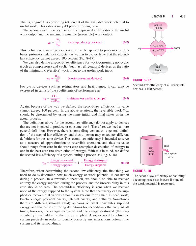
This definition is more general since it can be applied to processes (in tur-bines, piston–cylinder devices, etc.) as well as to cycles. Note that the second-law efficiency cannot exceed 100 percent (Fig. 8–17).
We can also define a second-law efficiency for work-consuming noncyclic(such as compressors) and cyclic (such as refrigerators) devices as the ratioof the minimum (reversible) work input to the useful work input:
(8–8)
For cyclic devices such as refrigerators and heat pumps, it can also beexpressed in terms of the coefficients of performance as
(8–9)
Again, because of the way we defined the second-law efficiency, its valuecannot exceed 100 percent. In the above relations, the reversible work Wrev
should be determined by using the same initial and final states as in theactual process.
The definitions above for the second-law efficiency do not apply to devicesthat are not intended to produce or consume work. Therefore, we need a moregeneral definition. However, there is some disagreement on a general defini-tion of the second-law efficiency, and thus a person may encounter differentdefinitions for the same device. The second-law efficiency is intended to serveas a measure of approximation to reversible operation, and thus its valueshould range from zero in the worst case (complete destruction of exergy) toone in the best case (no destruction of exergy). With this in mind, we definethe second-law efficiency of a system during a process as (Fig. 8–18)
(8–10)
Therefore, when determining the second-law efficiency, the first thing weneed to do is determine how much exergy or work potential is consumedduring a process. In a reversible operation, we should be able to recoverentirely the exergy supplied during the process, and the irreversibility in thiscase should be zero. The second-law efficiency is zero when we recovernone of the exergy supplied to the system. Note that the exergy can be sup-plied or recovered at various amounts in various forms such as heat, work,kinetic energy, potential energy, internal energy, and enthalpy. Sometimesthere are differing (though valid) opinions on what constitutes suppliedexergy, and this causes differing definitions for second-law efficiency. At alltimes, however, the exergy recovered and the exergy destroyed (the irre-versibility) must add up to the exergy supplied. Also, we need to define thesystem precisely in order to identify correctly any interactions between thesystem and its surroundings.
hII �
Exergy recovered
Exergy supplied� 1 �
Exergy destroyed
Exergy supplied
hII �COP
COPrev
ÉÉ1refrigerators and heat pumps 2
hII �Wrev
Wu
ÉÉ1work-consuming devices 2
hII �Wu
Wrev
ÉÉ1work-producing devices 2
Chapter 8 | 433
100%ηΙΙrev = 70%ηth = 70%η
Source1000 K
Sink300 K
FIGURE 8–17
Second-law efficiency of all reversibledevices is 100 percent.
Atmosphere
25°C
HeatHot
water
80°C
FIGURE 8–18
The second-law efficiency of naturallyoccurring processes is zero if none ofthe work potential is recovered.

For a heat engine, the exergy supplied is the decrease in the exergy of theheat transferred to the engine, which is the difference between the exergy ofthe heat supplied and the exergy of the heat rejected. (The exergy of theheat rejected at the temperature of the surroundings is zero.) The net workoutput is the recovered exergy.
For a refrigerator or heat pump, the exergy supplied is the work inputsince the work supplied to a cyclic device is entirely available. The recov-ered exergy is the exergy of the heat transferred to the high-temperaturemedium (which is the reversible work) for a heat pump, and the exergy ofthe heat transferred from the low-temperature medium for a refrigerator.
For a heat exchanger with two unmixed fluid streams, normally theexergy supplied is the decrease in the exergy of the higher-temperature fluidstream, and the exergy recovered is the increase in the exergy of the lower-temperature fluid stream. This is discussed further in Sec. 8–8.
434 | Thermodynamics
EXAMPLE 8–6 Second-Law Efficiency of Resistance Heaters
A dealer advertises that he has just received a shipment of electric resis-
tance heaters for residential buildings that have an efficiency of 100 percent
(Fig. 8–19). Assuming an indoor temperature of 21°C and outdoor tempera-
ture of 10°C, determine the second-law efficiency of these heaters.
Solution Electric resistance heaters are being considered for residential
buildings. The second-law efficiency of these heaters is to be determined.
Analysis Obviously the efficiency that the dealer is referring to is the first-
law efficiency, meaning that for each unit of electric energy (work) con-
sumed, the heater will supply the house with 1 unit of energy (heat). That is,
the advertised heater has a COP of 1.
At the specified conditions, a reversible heat pump would have a coeffi-
cient of the performance of
That is, it would supply the house with 26.7 units of heat (extracted from
the cold outside air) for each unit of electric energy it consumes.
The second-law efficiency of this resistance heater is
which does not look so impressive. The dealer will not be happy to see this
value. Considering the high price of electricity, a consumer will probably be
better off with a “less” efficient gas heater.
hII �COP
COPrev
�1.0
26.7� 0.037 or 3.7%
COPHP,rev �1
1 � TL>TH
�1
1 � 1283 K 2 > 1294 K 2 � 26.7
8–4 ■ EXERGY CHANGE OF A SYSTEM
The property exergy is the work potential of a system in a specified environ-ment and represents the maximum amount of useful work that can beobtained as the system is brought to equilibrium with the environment.
21°C
Resistance heater 10°C
FIGURE 8–19
Schematic for Example 8–6.
SEE TUTORIAL CH. 8, SEC. 4 ON THE DVD.
INTERACTIVE
TUTORIAL

Unlike energy, the value of exergy depends on the state of the environmentas well as the state of the system. Therefore, exergy is a combination prop-erty. The exergy of a system that is in equilibrium with its environment iszero. The state of the environment is referred to as the “dead state” since thesystem is practically “dead” (cannot do any work) from a thermodynamicpoint of view when it reaches that state.
In this section we limit the discussion to thermo-mechanical exergy, andthus disregard any mixing and chemical reactions. Therefore, a system atthis “restricted dead state” is at the temperature and pressure of the environ-ment and it has no kinetic or potential energies relative to the environment.However, it may have a different chemical composition than the environ-ment. Exergy associated with different chemical compositions and chemicalreactions is discussed in later chapters.
Below we develop relations for the exergies and exergy changes for afixed mass and a flow stream.
Exergy of a Fixed Mass:Nonflow (or Closed System) ExergyIn general, internal energy consists of sensible, latent, chemical, and nuclear
energies. However, in the absence of any chemical or nuclear reactions, thechemical and nuclear energies can be disregarded and the internal energy canbe considered to consist of only sensible and latent energies that can betransferred to or from a system as heat whenever there is a temperature dif-ference across the system boundary. The second law of thermodynamicsstates that heat cannot be converted to work entirely, and thus the workpotential of internal energy must be less than the internal energy itself. Buthow much less?
To answer that question, we need to consider a stationary closed system ata specified state that undergoes a reversible process to the state of the envi-ronment (that is, the final temperature and pressure of the system should beT0 and P0, respectively). The useful work delivered during this process is theexergy of the system at its initial state (Fig. 8–20).
Consider a piston–cylinder device that contains a fluid of mass m at tem-perature T and pressure P. The system (the mass inside the cylinder) has avolume V, internal energy U, and entropy S. The system is now allowed toundergo a differential change of state during which the volume changes by adifferential amount dV and heat is transferred in the differential amount ofdQ. Taking the direction of heat and work transfers to be from the system(heat and work outputs), the energy balance for the system during this dif-ferential process can be expressed as
(8–11)
Net energy transfer Change in internal, kinetic,by heat, work, and mass potential, etc., energies
since the only form of energy the system contains is internal energy, and theonly forms of energy transfer a fixed mass can involve are heat and work.Also, the only form of work a simple compressible system can involve duringa reversible process is the boundary work, which is given to be dW � P dV
� dQ � dW � dU
dE in � dEoutÉ�ÉÉdE system
Chapter 8 | 435
HEATENGINE
P
TP0
P0
δWb,useful
δWHE
δQ
T0
T0
FIGURE 8–20
The exergy of a specified mass at aspecified state is the useful work thatcan be produced as the massundergoes a reversible process to thestate of the environment.

when the direction of work is taken to be from the system (otherwise itwould be �P dV). The pressure P in the P dV expression is the absolute pres-sure, which is measured from absolute zero. Any useful work delivered by apiston–cylinder device is due to the pressure above the atmospheric level.Therefore,
(8–12)
A reversible process cannot involve any heat transfer through a finite tem-perature difference, and thus any heat transfer between the system at tem-perature T and its surroundings at T0 must occur through a reversible heatengine. Noting that dS � dQ/T for a reversible process, and the thermal effi-ciency of a reversible heat engine operating between the temperatures of Tand T0 is hth � 1 � T0/T, the differential work produced by the engine as aresult of this heat transfer is
(8–13)
Substituting the dW and dQ expressions in Eqs. 8–12 and 8–13 into theenergy balance relation (Eq. 8–11) gives, after rearranging,
Integrating from the given state (no subscript) to the dead state (0 subscript)we obtain
(8–14)
where Wtotal useful is the total useful work delivered as the system undergoes areversible process from the given state to the dead state, which is exergy bydefinition.
A closed system, in general, may possess kinetic and potential energies,and the total energy of a closed system is equal to the sum of its internal,kinetic, and potential energies. Noting that kinetic and potential energiesthemselves are forms of exergy, the exergy of a closed system of mass m is
(8–15)
On a unit mass basis, the closed system (or nonflow) exergy f is expressed as
(8–16)
where u0, v0, and s0 are the properties of the system evaluated at the deadstate. Note that the exergy of a system is zero at the dead state since e � e0,v � v0, and s � s0 at that state.
The exergy change of a closed system during a process is simply the dif-ference between the final and initial exergies of the system,
(8–17)
� 1U2 � U1 2 � P0 1V2 � V1 2 � T0 1S2 � S1 2 � mV 2
2 � V 21
2� mg 1z2 � z1 2
¢X � X 2 � X 1 � m 1f2 � f1 2 � 1E2 � E1 2 � P0 1V2 � V1 2 � T0 1S2 � S1 2
� 1e � e0 2 � P0 1v � v0 2 � T0 1s � s0 2 f � 1u � u0 2 � P0 1v � v0 2 � T0 1s � s0 2 �
V 2
2� gz
X � 1U � U0 2 � P0 1V � V0 2 � T0 1S � S0 2 � m V 2
2� mgz
Wtotal useful � 1U � U0 2 � P0 1V � V0 2 � T0 1S � S0 2
dWtotal useful � dWHE � dWb,useful � �dU � P0 dV � T0 dS
dQ � dWHE � T0 dS
dWHE � a1 �T0
Tb dQ � dQ �
T0
T dQ � dQ � 1�T0 dS 2 S
dW � P dV � 1P � P0 2 dV � P0 dV � dWb,useful � P0 dV
436 | Thermodynamics

or, on a unit mass basis,
(8–18)
For stationary closed systems, the kinetic and potential energy terms drop out.When the properties of a system are not uniform, the exergy of the system
can be determined by integration from
(8–19)
where V is the volume of the system and r is density.Note that exergy is a property, and the value of a property does not
change unless the state changes. Therefore, the exergy change of a system iszero if the state of the system or the environment does not change duringthe process. For example, the exergy change of steady flow devices such asnozzles, compressors, turbines, pumps, and heat exchangers in a given envi-ronment is zero during steady operation.
The exergy of a closed system is either positive or zero. It is never negative.Even a medium at low temperature (T � T0) and/or low pressure (P � P0)contains exergy since a cold medium can serve as the heat sink to a heatengine that absorbs heat from the environment at T0, and an evacuated spacemakes it possible for the atmospheric pressure to move a piston and do usefulwork (Fig. 8–21).
Exergy of a Flow Stream: Flow (or Stream) ExergyIn Chap. 5 it was shown that a flowing fluid has an additional form ofenergy, called the flow energy, which is the energy needed to maintain flowin a pipe or duct, and was expressed as wflow � Pv where v is the specificvolume of the fluid, which is equivalent to the volume change of a unit massof the fluid as it is displaced during flow. The flow work is essentially theboundary work done by a fluid on the fluid downstream, and thus the exergyassociated with flow work is equivalent to the exergy associated with theboundary work, which is the boundary work in excess of the work doneagainst the atmospheric air at P0 to displace it by a volume v (Fig. 8–22).Noting that the flow work is Pv and the work done against the atmosphereis P0v, the exergy associated with flow energy can be expressed as
(8–20)
Therefore, the exergy associated with flow energy is obtained by replacingthe pressure P in the flow work relation by the pressure in excess of theatmospheric pressure, P � P0. Then the exergy of a flow stream is deter-mined by simply adding the flow exergy relation above to the exergy rela-tion in Eq. 8–16 for a nonflowing fluid,
(8–21)
� 1u � u0 2 � P0 1v � v0 2 � T0 1s � s0 2 �V 2
2� gz � 1P � P0 2v
xflowing fluid � xnonflowing fluid � xflow
xflow � Pv � P0v � 1P � P0 2v
X system � � f dm � �V
fr dV
� 1e2 � e1 2 � P0 1v2 � v1 2 � T0 1s2 � s1 2¢f � f2 �f1 � 1u2 � u1 2 � P0 1v2 � v1 2 � T0 1s2 � s1 2 � V 2
2� V 21
2� g 1z2 � z1 2
Chapter 8 | 437
Atmosphere
T0 = 25°C
Work
output
Cold medium
T = 3°C
HEATENGINE
FIGURE 8–21
The exergy of a cold medium is also apositive quantity since work can beproduced by transferring heat to it.
P
v
P0
Pv = P0v + wshaft
wshaftFlowing
fluid
Imaginary piston
(represents the
fluid downstream)
Atmospheric
air displaced
v
FIGURE 8–22
The exergy associated with flow
energy is the useful work that wouldbe delivered by an imaginary piston in the flow section.

The final expression is called flow (or stream) exergy, and is denoted by c(Fig. 8–23).
Flow exergy: (8–22)
Then the exergy change of a fluid stream as it undergoes a process fromstate 1 to state 2 becomes
(8–23)
For fluid streams with negligible kinetic and potential energies, the kineticand potential energy terms drop out.
Note that the exergy change of a closed system or a fluid stream representsthe maximum amount of useful work that can be done (or the minimum
amount of useful work that needs to be supplied if it is negative) as the sys-tem changes from state 1 to state 2 in a specified environment, and repre-sents the reversible work Wrev. It is independent of the type of processexecuted, the kind of system used, and the nature of energy interactions withthe surroundings. Also note that the exergy of a closed system cannot be neg-ative, but the exergy of a flow stream can at pressures below the environmentpressure P0.
¢c � c2 � c1 � 1h2 � h1 2 � T0 1s2 � s1 2 �V 2
2 � V 21
2� g 1z2 � z1 2
c � 1h � h0 2 � T0 1s � s0 2 �V 2
2� gz
� 1h � h0 2 � T0 1s � s0 2 �V 2
2� gz
� 1u � Pv 2 � 1u0 � P0v0 2 � T0 1s � s0 2 �V 2
2� gz
438 | Thermodynamics
COMPRESSED
AIR
1 MPa
300 K
FIGURE 8–24
Schematic for Example 8–7.
Energy:Energy:
Exergy:Exergy:
(a) A fixed mass (nonflowing)) A fixed mass (nonflowing)
e = u u + + gzgzV 2
2FixedFixed
massmass
V 2
2f = (= (u u – u0) + + P0(v – v0) – T0(s s – s0) + + gzgz
Energy:Energy:
Exergy:Exergy:
(b) A fluid ) A fluid streamstream (flowing) (flowing)
u = h h + + gzgzV 2
2
V 2
2c = (= (h h – h0) + + T0(s s – s0) + + gzgz
FluidFluid
streamstream
FIGURE 8–23
The energy and exergy contents of(a) a fixed mass and (b) a fluid stream.
EXAMPLE 8–7 Work Potential of Compressed Air in a Tank
A 200-m3 rigid tank contains compressed air at 1 MPa and 300 K. Deter-
mine how much work can be obtained from this air if the environment condi-
tions are 100 kPa and 300 K.
Solution Compressed air stored in a large tank is considered. The work
potential of this air is to be determined.
Assumptions 1 Air is an ideal gas. 2 The kinetic and potential energies are
negligible.
Analysis We take the air in the rigid tank as the system (Fig. 8–24). This is
a closed system since no mass crosses the system boundary during the
process. Here the question is the work potential of a fixed mass, which is
the nonflow exergy by definition.
Taking the state of the air in the tank to be state 1 and noting that T1 �
T0 � 300 K, the mass of air in the tank is
m1 �P1V
RT1
�
11000 kPa 2 1200 m3 210.287 kPa # m3>kg # K 2 1300 K 2 � 2323 kg

Chapter 8 | 439
P1 = 0.14 MPa
T1 = –10°C
T2 = 50°C
P2 = 0.8 MPa
T0 = 20°C
COMPRESSOR
FIGURE 8–25
Schematic for Example 8–8.
The exergy content of the compressed air can be determined from
We note that
Therefore,
and
Discussion The work potential of the system is 281 MJ, and thus a maxi-
mum of 281 MJ of useful work can be obtained from the compressed air
stored in the tank in the specified environment.
X 1 � m1f1 � 12323 kg 2 1120.76 kJ>kg 2 � 280,525 kJ � 281 MJ
� 120.76 kJ>kg
� 10.287 kJ>kg # K 2 1300 K 2 a ln 1000 kPa
100 kPa�
100 kPa
1000 kPa� 1 b
f1 � RT0 a P0
P1
� 1 b � RT0 ln P1
P0
� RT0 a ln P1
P0
�P0
P1
� 1 b
T0 1s1 � s0 2 � T0 a cp ln T1
T0
� R ln P1
P0
b � �RT0 ln P1
P0
ÉÉ1since T1 � T0 2 P0 1v1 � v0 2 � P0 a RT1
P1
�RT0
P0
b � RT0 a P0
P1
� 1 bÉÉ1since T1 � T0 2 � m 3P0 1v1 � v0 2 � T0 1s1 � s0 2 4 � m c 1u1 � u0 2Q0
� P0 1v1 � v0 2 � T0 1s1 � s0 2 �V 2
1
2
Q0
� gz1Q
0 d X 1 � mf1
EXAMPLE 8–8 Exergy Change during a Compression Process
Refrigerant-134a is to be compressed from 0.14 MPa and �10°C to 0.8
MPa and 50°C steadily by a compressor. Taking the environment conditions
to be 20°C and 95 kPa, determine the exergy change of the refrigerant dur-
ing this process and the minimum work input that needs to be supplied to
the compressor per unit mass of the refrigerant.
Solution Refrigerant-134a is being compressed from a specified inlet state
to a specified exit state. The exergy change of the refrigerant and the mini-
mum compression work per unit mass are to be determined.
Assumptions 1 Steady operating conditions exist. 2 The kinetic and poten-
tial energies are negligible.
Analysis We take the compressor as the system (Fig. 8–25). This is a con-
trol volume since mass crosses the system boundary during the process.
Here the question is the exergy change of a fluid stream, which is the
change in the flow exergy c.

8–5 ■ EXERGY TRANSFER BY HEAT, WORK,AND MASS
Exergy, like energy, can be transferred to or from a system in three forms:heat, work, and mass flow. Exergy transfer is recognized at the systemboundary as exergy crosses it, and it represents the exergy gained or lost bya system during a process. The only two forms of exergy interactions asso-ciated with a fixed mass or closed system are heat transfer and work.
Exergy by Heat Transfer, QRecall from Chap. 6 that the work potential of the energy transferred froma heat source at temperature T is the maximum work that can be obtainedfrom that energy in an environment at temperature T0 and is equivalent tothe work produced by a Carnot heat engine operating between the sourceand the environment. Therefore, the Carnot efficiency hc � 1 � T0 /T rep-resents the fraction of energy of a heat source at temperature T that can beconverted to work (Fig. 8–26). For example, only 70 percent of the energytransferred from a heat source at T � 1000 K can be converted to work inan environment at T0 � 300 K.
440 | Thermodynamics
The properties of the refrigerant at the inlet and the exit states are
Inlet state:
Exit state:
The exergy change of the refrigerant during this compression process is
determined directly from Eq. 8–23 to be
Therefore, the exergy of the refrigerant increases during compression by
38.0 kJ/kg.
The exergy change of a system in a specified environment represents the
reversible work in that environment, which is the minimum work input
required for work-consuming devices such as compressors. Therefore, the
increase in exergy of the refrigerant is equal to the minimum work that
needs to be supplied to the compressor:
Discussion Note that if the compressed refrigerant at 0.8 MPa and 50°C
were to be expanded to 0.14 MPa and �10°C in a turbine in the same envi-
ronment in a reversible manner, 38.0 kJ/kg of work would be produced.
win,min � c2 � c1 � 38.0 kJ/kg
� 38.0 kJ/kg
� 1286.69 � 246.36 2 kJ>kg � 1293 K 2 3 10.9802 � 0.9724 2kJ>kg # K 4 � 1h2 � h1 2 � T0 1s2 � s1 2 ¢c � c2 � c1 � 1h2 � h1 2 � T0 1s2 � s1 2 �
V 22 � V 2
1
2
Q0
� g 1z2 � z1 2Q0
P2 � 0.8 MPa
T2 � 50°CfÉh2 � 286.69 kJ>kg
s2 � 0.9802 kJ>kg # K
P1 � 0.14 MPa
T1 � �10°CfÉh1 � 246.36 kJ>kg
s1 � 0.9724 kJ>kg # K
SEE TUTORIAL CH. 8, SEC. 5 ON THE DVD.
INTERACTIVE
TUTORIAL

Heat is a form of disorganized energy, and thus only a portion of it canbe converted to work, which is a form of organized energy (the secondlaw). We can always produce work from heat at a temperature above theenvironment temperature by transferring it to a heat engine that rejects thewaste heat to the environment. Therefore, heat transfer is always accom-panied by exergy transfer. Heat transfer Q at a location at thermodynamictemperature T is always accompanied by exergy transfer Xheat in theamount of
Exergy transfer by heat: (8–24)
This relation gives the exergy transfer accompanying heat transfer Q
whether T is greater than or less than T0. When T � T0, heat transfer to asystem increases the exergy of that system and heat transfer from a sys-tem decreases it. But the opposite is true when T � T0. In this case, theheat transfer Q is the heat rejected to the cold medium (the waste heat),and it should not be confused with the heat supplied by the environmentat T0. The exergy transferred with heat is zero when T � T0 at the pointof transfer.
Perhaps you are wondering what happens when T � T0. That is, what ifwe have a medium that is at a lower temperature than the environment? Inthis case it is conceivable that we can run a heat engine between the environ-ment and the “cold” medium, and thus a cold medium offers us an opportu-nity to produce work. However, this time the environment serves as the heatsource and the cold medium as the heat sink. In this case, the relation abovegives the negative of the exergy transfer associated with the heat Q trans-ferred to the cold medium. For example, for T � 100 K and a heat transferof Q � 1 kJ to the medium, Eq. 8–24 gives Xheat � (1 � 300/100)(1 kJ)� �2 kJ, which means that the exergy of the cold medium decreases by2 kJ. It also means that this exergy can be recovered, and the coldmedium–environment combination has the potential to produce 2 units ofwork for each unit of heat rejected to the cold medium at 100 K. That is,a Carnot heat engine operating between T0 � 300 K and T � 100 K pro-duces 2 units of work while rejecting 1 unit of heat for each 3 units ofheat it receives from the environment.
When T � T0, the exergy and heat transfer are in the same direction.That is, both the exergy and energy content of the medium to which heat istransferred increase. When T � T0 (cold medium), however, the exergy andheat transfer are in opposite directions. That is, the energy of the coldmedium increases as a result of heat transfer, but its exergy decreases. Theexergy of the cold medium eventually becomes zero when its temperaturereaches T0. Equation 8–24 can also be viewed as the exergy associated with
thermal energy Q at temperature T.
When the temperature T at the location where heat transfer is taking placeis not constant, the exergy transfer accompanying heat transfer is deter-mined by integration to be
(8–25)X heat � � a1 �T0
Tb dQ
X heat � a1 �T0
TbQÉÉ1kJ 2
Chapter 8 | 441
HEAT SOURCEHEAT SOURCE
Temperature: Temperature: T
Energy transferred: Energy transferred: E
Exergy = Exergy = 1 – T0 E(T(
T0
FIGURE 8–26
The Carnot efficiency hc � 1 � T0 /Trepresents the fraction of the energytransferred from a heat source attemperature T that can be converted to work in an environment attemperature T0.

Note that heat transfer through a finite temperature difference is irreversible,and some entropy is generated as a result. The entropy generation is alwaysaccompanied by exergy destruction, as illustrated in Fig. 8–27. Also notethat heat transfer Q at a location at temperature T is always accompanied byentropy transfer in the amount of Q/T and exergy transfer in the amount of(1 � T0 /T )Q.
Exergy Transfer by Work, WExergy is the useful work potential, and the exergy transfer by work cansimply be expressed as
Exergy transfer by work: (8–26)
where Wsurr � P0(V2 � V1), P0 is atmospheric pressure, and V1 and V2 are theinitial and final volumes of the system. Therefore, the exergy transfer withwork such as shaft work and electrical work is equal to the work W itself. Inthe case of a system that involves boundary work, such as a piston–cylinderdevice, the work done to push the atmospheric air out of the way duringexpansion cannot be transferred, and thus it must be subtracted. Also, duringa compression process, part of the work is done by the atmospheric air, andthus we need to supply less useful work from an external source.
To clarify this point further, consider a vertical cylinder fitted with aweightless and frictionless piston (Fig. 8–28). The cylinder is filled with agas that is maintained at the atmospheric pressure P0 at all times. Heat isnow transferred to the system and the gas in the cylinder expands. As aresult, the piston rises and boundary work is done. However, this work can-not be used for any useful purpose since it is just enough to push the atmo-spheric air aside. (If we connect the piston to an external load to extractsome useful work, the pressure in the cylinder will have to rise above P0 tobeat the resistance offered by the load.) When the gas is cooled, the pistonmoves down, compressing the gas. Again, no work is needed from an exter-nal source to accomplish this compression process. Thus we conclude thatthe work done by or against the atmosphere is not available for any usefulpurpose, and should be excluded from available work.
Exergy Transfer by Mass, mMass contains exergy as well as energy and entropy, and the exergy, energy,and entropy contents of a system are proportional to mass. Also, the rates ofexergy, entropy, and energy transport into or out of a system are proportionalto the mass flow rate. Mass flow is a mechanism to transport exergy, entropy,and energy into or out of a system. When mass in the amount of m entersor leaves a system, exergy in the amount of mc, where c � (h � h0) �
T0(s � s0) � V2/2 � gz, accompanies it. That is,
Exergy transfer by mass: (8–27)
Therefore, the exergy of a system increases by mc when mass in theamount of m enters, and decreases by the same amount when the sameamount of mass at the same state leaves the system (Fig. 8–29).
Xmass � mc
Xwork � eW � Wsurr 1for boundary work 2WÉ 1for other forms of work 2
442 | Thermodynamics
MEDIUM 1 MEDIUM 2
Wall
Q QHeattransfer
T1
T2
Entropytransfer
Entropygenerated
Q
T1
Q
T2
Exergytransfer
Exergydestroyed
1 – T0 Q(T1( 1 – T0 Q(T2
(
FIGURE 8–27
The transfer and destruction of exergyduring a heat transfer process througha finite temperature difference.
Weightlesspiston
P0
Heat
P0
FIGURE 8–28
There is no useful work transferassociated with boundary work whenthe pressure of the system ismaintained constant at atmosphericpressure.

Exergy flow associated with a fluid stream when the fluid properties arevariable can be determined by integration from
(8–28)
where Ac is the cross-sectional area of the flow and Vn is the local velocitynormal to dAc.
Note that exergy transfer by heat Xheat is zero for adiabatic systems, and theexergy transfer by mass Xmass is zero for systems that involve no mass flowacross their boundaries (i.e., closed systems). The total exergy transfer iszero for isolated systems since they involve no heat, work, or mass transfer.
8–6 ■ THE DECREASE OF EXERGY PRINCIPLEAND EXERGY DESTRUCTION
In Chap. 2 we presented the conservation of energy principle and indicatedthat energy cannot be created or destroyed during a process. In Chap. 7 weestablished the increase of entropy principle, which can be regarded as oneof the statements of the second law, and indicated that entropy can be cre-ated but cannot be destroyed. That is, entropy generation Sgen must be posi-tive (actual processes) or zero (reversible processes), but it cannot benegative. Now we are about to establish an alternative statement of the sec-ond law of thermodynamics, called the decrease of exergy principle, whichis the counterpart of the increase of entropy principle.
Consider an isolated system shown in Fig. 8–30. By definition, no heat,work, or mass can cross the boundaries of an isolated system, and thus thereis no energy and entropy transfer. Then the energy and entropy balances foran isolated system can be expressed as
Energy balance:
Entropy balance:
Multiplying the second relation by T0 and subtracting it from the first onegives
(8–29)
From Eq. 8–17 we have
(8–30)
since V2 � V1 for an isolated system (it cannot involve any moving bound-ary and thus any boundary work). Combining Eqs. 8–29 and 8–30 gives
(8–31)
since T0 is the thermodynamic temperature of the environment and thus apositive quantity, Sgen � 0, and thus T0Sgen � 0. Then we conclude that
(8–32)¢X isolated � 1X 2 � X 1 2 isolated � 0
�T0 Sgen � X2 � X1 � 0
� 1E2 � E1 2 � T0 1S2 � S1 2 X2 � X1 � 1E2 � E1 2 � P0 1V2 � V1 2Q0
� T0 1S2 � S1 2�T0 Sgen � E2 � E1 � T0 1S2 � S1 2
SinQ
0� S out
Q0
� Sgen � ¢SsystemS Sgen � S2 � S1
EinQ
0� Eout
Q0
� ¢EsystemS 0 � E2 � E1
X#
mass � �Ac
crVn dAcÉandÉXmass � � c dm � �¢t
X#
mass dt
Chapter 8 | 443
···
·
Control volume
h
sψ ψ
m
mh
ms
m
FIGURE 8–29
Mass contains energy, entropy, andexergy, and thus mass flow into or outof a system is accompanied by energy,entropy, and exergy transfer.
No heat, workor mass transfer
Isolated system
∆X isolated ≤ 0
(or X destroyed ≥ 0)
FIGURE 8–30
The isolated system considered in thedevelopment of the decrease of exergyprinciple.
SEE TUTORIAL CH. 8, SEC. 6 ON THE DVD.
INTERACTIVE
TUTORIAL

This equation can be expressed as the exergy of an isolated system during a
process always decreases or, in the limiting case of a reversible process,
remains constant. In other words, it never increases and exergy is destroyed
during an actual process. This is known as the decrease of exergy princi-
ple. For an isolated system, the decrease in exergy equals exergy destroyed.
Exergy DestructionIrreversibilities such as friction, mixing, chemical reactions, heat transferthrough a finite temperature difference, unrestrained expansion, nonquasi-equilibrium compression or expansion always generate entropy, and any-thing that generates entropy always destroys exergy. The exergy destroyed
is proportional to the entropy generated, as can be seen from Eq. 8–31, andis expressed as
(8–33)
Note that exergy destroyed is a positive quantity for any actual process andbecomes zero for a reversible process. Exergy destroyed represents the lostwork potential and is also called the irreversibility or lost work.
Equations 8–32 and 8–33 for the decrease of exergy and the exergy destruc-tion are applicable to any kind of system undergoing any kind of process sinceany system and its surroundings can be enclosed by a sufficiently large arbi-trary boundary across which there is no heat, work, and mass transfer, andthus any system and its surroundings constitute an isolated system.
No actual process is truly reversible, and thus some exergy is destroyedduring a process. Therefore, the exergy of the universe, which can be con-sidered to be an isolated system, is continuously decreasing. The more irre-versible a process is, the larger the exergy destruction during that process.No exergy is destroyed during a reversible process (Xdestroyed,rev � 0).
The decrease of exergy principle does not imply that the exergy of a sys-tem cannot increase. The exergy change of a system can be positive or neg-ative during a process (Fig. 8–31), but exergy destroyed cannot be negative.The decrease of exergy principle can be summarized as follows:
(8–34)
This relation serves as an alternative criterion to determine whether aprocess is reversible, irreversible, or impossible.
8–7 ■ EXERGY BALANCE: CLOSED SYSTEMS
The nature of exergy is opposite to that of entropy in that exergy can bedestroyed, but it cannot be created. Therefore, the exergy change of a sys-tem during a process is less than the exergy transfer by an amount equal tothe exergy destroyed during the process within the system boundaries. Thenthe decrease of exergy principle can be expressed as (Fig. 8–32)
° Total
exergy
entering
¢ � ° Total
exergy
leaving
¢ � ° Total
exergy
destroyed
¢ � °Change in the
total exergy
of the system
¢
X destroyed • 7 0ÉIrreversible process
� 0ÉReversible process
6 0ÉImpossible process
X destroyed � T0 Sgen � 0
444 | Thermodynamics
SurroundingsSurroundings
SYSTEMSYSTEM
∆ Xsyssys = = –2 kJ2 kJ
Xdestdest = 1 kJ = 1 kJ
Q
FIGURE 8–31
The exergy change of a system can benegative, but the exergy destructioncannot.
SEE TUTORIAL CH. 8, SEC. 7 ON THE DVD.
INTERACTIVE
TUTORIAL

or
(8–35)
This relation is referred to as the exergy balance and can be stated as the
exergy change of a system during a process is equal to the difference
between the net exergy transfer through the system boundary and the exergy
destroyed within the system boundaries as a result of irreversibilities.
We mentioned earlier that exergy can be transferred to or from a systemby heat, work, and mass transfer. Then the exergy balance for any system
undergoing any process can be expressed more explicitly as
General: (8–36)
Net exergy transfer Exergy Changeby heat, work, and mass destruction in exergy
or, in the rate form, as
General, rate form: (8–37)
Rate of net exergy transfer Rate of exergy Rate of changeby heat, work, and mass destruction in exergy
where the rates of exergy transfer by heat, work, and mass are expressedas X
.heat � (1 � T0 /T )Q
., X
.work � W
.useful, and X
.mass � m
.c, respectively. The
exergy balance can also be expressed per unit mass as
General, unit-mass basis: (8–38)
where all the quantities are expressed per unit mass of the system. Note thatfor a reversible process, the exergy destruction term Xdestroyed drops out fromall of the relations above. Also, it is usually more convenient to find theentropy generation Sgen first, and then to evaluate the exergy destroyeddirectly from Eq. 8–33. That is,
(8–39)
When the environment conditions P0 and T0 and the end states of the systemare specified, the exergy change of the system �Xsystem � X2 � X1 can bedetermined directly from Eq. 8–17 regardless of how the process is exe-cuted. However, the determination of the exergy transfers by heat, work, andmass requires a knowledge of these interactions.
A closed system does not involve any mass flow and thus any exergytransfer associated with mass flow. Taking the positive direction of heattransfer to be to the system and the positive direction of work transfer to befrom the system, the exergy balance for a closed system can be expressedmore explicitly as (Fig. 8–33)
Closed system: (8–40)
or
Closed system: (8–41)a a1 �T0
Tk
bQ k � 3W � P0 1V2 � V1 2 4 � T0 Sgen � X 2 � X 1
Xheat � Xwork � Xdestroyed � ¢Xsystem
X destroyed � T0 SgenÉorÉX#
destroyed � T0 S#gen
1xin � xout 2 � xdestroyed � ¢xsystemÉÉ1kJ>kg 2
X#
in � X#
outÉ � X#
destroyed � dX system>dt 1kW 2
X in � X outÉ � X destroyed � ¢X system 1kJ 2
Xin � Xout � Xdestroyed � ¢Xsystem
Chapter 8 | 445
System
∆Xsystem
Xdestroyed
Xin Xout
Mass
Heat
Work
Mass
Heat
Work
FIGURE 8–32
Mechanisms of exergy transfer.
∆XsystemXdestroyed
Q
Xheat
Xheat – Xwork – Xdestroyed = ∆Xsystem
W
Xwork
FIGURE 8–33
Exergy balance for a closed systemwhen the direction of heat transfer istaken to be to the system and thedirection of work from the system.

where Qk is the heat transfer through the boundary at temperature Tk at loca-tion k. Dividing the previous equation by the time interval �t and taking thelimit as �t → 0 gives the rate form of the exergy balance for a closed system,
Rate form: (8–42)
Note that the relations above for a closed system are developed by takingthe heat transfer to a system and work done by the system to be positivequantities. Therefore, heat transfer from the system and work done on thesystem should be taken to be negative quantities when using those relations.
The exergy balance relations presented above can be used to determinethe reversible work Wrev by setting the exergy destruction term equal to zero.The work W in that case becomes the reversible work. That is, W � Wrev
when Xdestroyed � T0Sgen � 0.Note that Xdestroyed represents the exergy destroyed within the system bound-
ary only, and not the exergy destruction that may occur outside the systemboundary during the process as a result of external irreversibilities. Therefore,a process for which Xdestroyed � 0 is internally reversible but not necessarilytotally reversible. The total exergy destroyed during a process can be deter-mined by applying the exergy balance to an extended system that includes thesystem itself and its immediate surroundings where external irreversibilitiesmight be occurring (Fig. 8–34). Also, the exergy change in this case is equalto the sum of the exergy changes of the system and the exergy change of theimmediate surroundings. Note that under steady conditions, the state and thusthe exergy of the immediate surroundings (the “buffer zone”) at any pointdoes not change during the process, and thus the exergy change of the imme-diate surroundings is zero. When evaluating the exergy transfer between anextended system and the environment, the boundary temperature of theextended system is simply taken to be the environment temperature T0.
For a reversible process, the entropy generation and thus the exergy
destruction are zero, and the exergy balance relation in this case becomesanalogous to the energy balance relation. That is, the exergy change of thesystem becomes equal to the exergy transfer.
Note that the energy change of a system equals the energy transfer forany process, but the exergy change of a system equals the exergy transfer
only for a reversible process. The quantity of energy is always preservedduring an actual process (the first law), but the quality is bound to decrease(the second law). This decrease in quality is always accompanied by anincrease in entropy and a decrease in exergy. When 10 kJ of heat is trans-ferred from a hot medium to a cold one, for example, we still have 10 kJ ofenergy at the end of the process, but at a lower temperature, and thus at alower quality and at a lower potential to do work.
a a1 �T0
Tk
bQ#
k � aW#
� P0 dVsystem
dtb � T0 S
#gen �
dX system
dt
446 | Thermodynamics
ImmediateImmediate
surroundingssurroundings
SYSTEMSYSTEM
Q
T0
OuterOuter
surroundingssurroundings
(environment)(environment)
T0
FIGURE 8–34
Exergy destroyed outside systemboundaries can be accounted for bywriting an exergy balance on theextended system that includes thesystem and its immediatesurroundings.
EXAMPLE 8–9 General Exergy Balance for Closed Systems
Starting with energy and entropy balances, derive the general exergy balance
relation for a closed system (Eq. 8–41).
Solution Starting with energy and entropy balance relations, a general rela-
tion for exergy balance for a closed system is to be obtained.

Chapter 8 | 447
Analysis We consider a general closed system (a fixed mass) that is free to
exchange heat and work with its surroundings (Fig. 8–35). The system under-
goes a process from state 1 to state 2. Taking the positive direction of heat
transfer to be to the system and the positive direction of work transfer to be
from the system, the energy and entropy balances for this closed system can
be expressed as
Energy balance:
Entropy
balance:
Multiplying the second relation by T0 and subtracting it from the first one gives
However, the heat transfer for the process 1-2 can be expressed as
and the right side of the above equation is, from Eq. 8–17, (X2 � X1) �
P0(V2 � V1). Thus,
Letting Tb denote the boundary temperature and rearranging give
(8–43)
which is equivalent to Eq. 8–41 for the exergy balance except that the inte-
gration is replaced by summation in that equation for convenience. This
completes the proof.
Discussion Note that the exergy balance relation above is obtained by
adding the energy and entropy balance relations, and thus it is not an inde-
pendent equation. However, it can be used in place of the entropy balance
relation as an alternative second law expression in exergy analysis.
�2
1
a1 �T0
Tb
b dQ � 3W � P0 1V2 � V1 2 4 � T0 Sgen � X 2 � X 1
�2
1
dQ � T0�2
1
a dQTb
boundary
� W � T0 Sgen � X 2 � X 1 � P0 1V2 � V1 2
Q � �2
1
dQ
Q � T0�2
1
a dQTb
boundary
� W � T0 Sgen � E2 � E1 � T0 1S2 � S1 2
Sin � Sout � Sgen � ¢Ssystem S �2
1
a dQTb
boundary
� Sgen � S2 � S1
Ein � Eout � ¢Esystem S Q � W � E2 � E1
EXAMPLE 8–10 Exergy Destruction during Heat Conduction
Consider steady heat transfer through a 5-m � 6-m brick wall of a house of
thickness 30 cm. On a day when the temperature of the outdoors is 0°C, the
house is maintained at 27°C. The temperatures of the inner and outer sur-
faces of the brick wall are measured to be 20°C and 5°C, respectively, and
the rate of heat transfer through the wall is 1035 W. Determine the rate of
exergy destruction in the wall, and the rate of total exergy destruction associ-
ated with this heat transfer process.
Solution Steady heat transfer through a wall is considered. For specified
heat transfer rate, wall surface temperatures, and environment conditions,
the rate of exergy destruction within the wall and the rate of total exergy
destruction are to be determined.
Assumptions 1 The process is steady, and thus the rate of heat transfer
through the wall is constant. 2 The exergy change of the wall is zero during
Closedsystem
Q
W
Tb
FIGURE 8–35
A general closed system considered inExample 8–9.

448 | Thermodynamics
this process since the state and thus the exergy of the wall do not change
anywhere in the wall. 3 Heat transfer through the wall is one-dimensional.
Analysis We first take the wall as the system (Fig. 8–36). This is a closed
system since no mass crosses the system boundary during the process. We
note that heat and exergy are entering from one side of the wall and leaving
from the other side.
Applying the rate form of the exergy balance to the wall gives
Rate of net exergy transfer Rate of exergy Rate of changeby heat, work, and mass destruction in exergy
Solving, the rate of exergy destruction in the wall is determined to be
Note that exergy transfer with heat at any location is (1 � T0/T)Q at that
location, and the direction of exergy transfer is the same as the direction of
heat transfer.
To determine the rate of total exergy destruction during this heat trans-
fer process, we extend the system to include the regions on both sides of
the wall that experience a temperature change. Then one side of the sys-
tem boundary becomes room temperature while the other side, the tem-
perature of the outdoors. The exergy balance for this extended system
(system + immediate surroundings) is the same as that given above,
except the two boundary temperatures are 300 and 273 K instead of 293
and 278 K, respectively. Then the rate of total exergy destruction becomes
The difference between the two exergy destructions is 41.2 W and repre-
sents the exergy destroyed in the air layers on both sides of the wall. The
exergy destruction in this case is entirely due to irreversible heat transfer
through a finite temperature difference.
Discussion This problem was solved in Chap. 7 for entropy generation. We
could have determined the exergy destroyed by simply multiplying the
entropy generations by the environment temperature of T0 � 273 K.
X#
destroyed,total � 11035 W 2 a1 �273 K
300 Kb � 11035 W 2 a1 �
273 K
273 Kb � 93.2 W
X#
destroyed � 52.0 W
11035 W 2 a1 �273 K
293 Kb � 11035 W 2 a1 �
273 K
278 Kb � X
#destroyed � 0
Q# a1 �
T0
Tb
in
� Q# a1 �
T0
Tb
out
� X#
destroyed � 0
X#
in � X#
outÉ � X#
destroyed � dX system>dt � 0
EXAMPLE 8–11 Exergy Destruction during Expansion of Steam
A piston–cylinder device contains 0.05 kg of steam at 1 MPa and 300°C.
Steam now expands to a final state of 200 kPa and 150°C, doing work. Heat
losses from the system to the surroundings are estimated to be 2 kJ during this
process. Assuming the surroundings to be at T0 � 25°C and P0 � 100 kPa,
·
Brickwall
27°C 0°C
Q
30 cm
20°C 5°C
FIGURE 8–36
Schematic for Example 8–10.⎫⎪⎬⎪⎭ ⎫⎪⎬⎪⎭ ⎫⎪⎪⎪⎪⎬⎪⎪⎪⎪⎭
0 (steady)
¡

Chapter 8 | 449
determine (a) the exergy of the steam at the initial and the final states, (b) the
exergy change of the steam, (c) the exergy destroyed, and (d) the second-law
efficiency for the process.
Solution Steam in a piston–cylinder device expands to a specified state. The
exergies of steam at the initial and final states, the exergy change, the exergy
destroyed, and the second-law efficiency for this process are to be determined.
Assumptions The kinetic and potential energies are negligible.
Analysis We take the steam contained within the piston–cylinder device as
the system (Fig. 8–37). This is a closed system since no mass crosses the
system boundary during the process. We note that boundary work is done by
the system and heat is lost from the system during the process.
(a) First we determine the properties of the steam at the initial and final
states as well as the state of the surroundings:
State 1:
State 2:
Dead state:
The exergies of the system at the initial state X1 and the final state X2 are
determined from Eq. 8–15 to be
and
That is, steam initially has an exergy content of 35 kJ, which drops to 25.4
kJ at the end of the process. In other words, if the steam were allowed to
undergo a reversible process from the initial state to the state of the environ-
ment, it would produce 35 kJ of useful work.
(b) The exergy change for a process is simply the difference between the
exergy at the initial and final states of the process,
¢X � X 2 � X 1 � 25.4 � 35.0 � �9.6 kJ
� 25.4 kJ
� 1100 kPa 2 3 10.95986 � 0.00103 2 m3>kg 4 6 1kJ>kPa # m3 2 � 1298 K 2 3 17.2810 � 0.3672 2 kJ>kg # K 4 � 10.05 kg 2 5 12577.1 � 104.83 2 kJ>kg
X 2 � m 3 1u2 � u0 2 � T0 1s2 � s0 2 � P0 1v2 � v0 2 4 � 35.0 kJ
� 1100 kPa 2 3 10.25799 � 0.00103 2 m3>kg 4 6 1kJ>kPa # m3 2 � 1298 K 2 3 17.1246 � 0.3672 2 kJ>kg # K 4 � 10.05 kg 2 5 12793.7 � 104.83 2 kJ>kg
X 1 � m 3 1u1 � u0 2 � T0 1s1 � s0 2 � P0 1v1 � v0 2 4
P0 � 100 kPa
T0 � 25°CfÉu0 � uf @ 25°C � 104.83 kJ>kg
v0 � vf @ 25°C � 0.00103 m3>kg
s0 � sf @ 25°C � 0.3672 kJ>kg # KÉÉ1Table A–4 2
P2 � 200 kPa
T2 � 150°CfÉu2 � 2577.1 kJ>kg
v2 � 0.95986 m3>kgÉÉ1Table A–6 2s2 � 7.2810 kJ>kg # K
P1 � 1 MPa
T1 � 300°CfÉu1 � 2793.7 kJ>kg
v1 � 0.25799 m3>kg
s1 � 7.1246 kJ>kg # KÉÉ1Table A–6 2 2 kJ
P1 = 1 MP
T1 = 300°C
P2 = 200 kPa
T2 = 150°C
Steam
P0 = 100 kPa
T0 = 25°C
State 1 State 2
FIGURE 8–37
Schematic for Example 8–11.

450 | Thermodynamics
That is, if the process between states 1 and 2 were executed in a reversible
manner, the system would deliver 9.6 kJ of useful work.
(c) The total exergy destroyed during this process can be determined from
the exergy balance applied on the extended system (system + immediate
surroundings) whose boundary is at the environment temperature of T0 (so
that there is no exergy transfer accompanying heat transfer to or from the
environment),
Net exergy transfer Exergy Changeby heat, work, and mass destruction in exergy
where Wu,out is the useful boundary work delivered as the system expands. By
writing an energy balance on the system, the total boundary work done dur-
ing the process is determined to be
Net energy transfer Change in internal, kinetic,by heat, work, and mass potential, etc., energies
This is the total boundary work done by the system, including the work done
against the atmosphere to push the atmospheric air out of the way during
the expansion process. The useful work is the difference between the two:
Substituting, the exergy destroyed is determined to be
That is, 4.3 kJ of work potential is wasted during this process. In other
words, an additional 4.3 kJ of energy could have been converted to work
during this process, but was not.
The exergy destroyed could also be determined from
which is the same result obtained before.
� 4.3 kJ
� 1298 K 2 e 10.05 kg 2 3 17.2810 � 7.1246 2 kJ>kg # K 4 �2 kJ
298 Kf
X destroyed � T0 Sgen � T0 cm 1s2 � s1 2 �Q surr
T0
d
X destroyed � X 1 � X 2 � Wu,out � 35.0 � 25.4 � 5.3 � 4.3 kJ
� 5.3 kJ
� 8.8 kJ � 1100 kPa 2 10.05 kg 2 3 10.9599 � 0.25799 2 m3>kg 4 a 1 kJ
1 kPa # m3b
Wu � W � Wsurr � Wb,out � P0 1V2 � V1 2 � Wb,out � P0 m 1v2 � v1 2
� 8.8 kJ
� � 12 kJ 2 � 10.05 kg 2 12577.1 � 2793.7 2 kJ>kg
Wb,out � �Q out � ¢U � �Q out � m 1u2 � u1 2 �Q out � Wb,out � ¢U
E in � EoutÉ �É ¢E system
X destroyed � X 1 � X 2 � Wu,out
�Xwork,out � X heat,out � X destroyed � X 2 � X 1
X in � X outÉ � X destroyed � ¢X system
0¡
⎫⎪⎬⎪⎭ ⎫⎪⎬⎪⎭ ⎫⎪⎬⎪⎭
⎫⎪⎬⎪⎭ ⎫⎪⎬⎪⎭
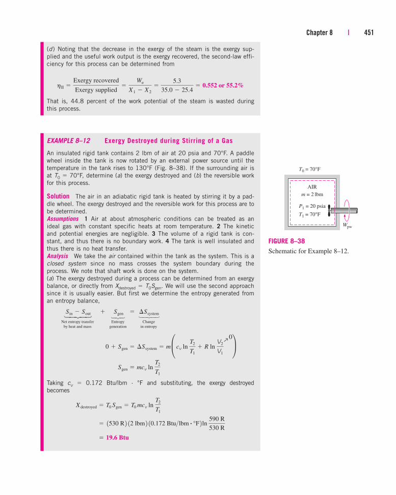
Chapter 8 | 451
(d) Noting that the decrease in the exergy of the steam is the exergy sup-
plied and the useful work output is the exergy recovered, the second-law effi-
ciency for this process can be determined from
That is, 44.8 percent of the work potential of the steam is wasted during
this process.
hII �Exergy recovered
Exergy supplied�
Wu
X 1 � X 2
�5.3
35.0 � 25.4� 0.552 or 55.2%
EXAMPLE 8–12 Exergy Destroyed during Stirring of a Gas
An insulated rigid tank contains 2 lbm of air at 20 psia and 70°F. A paddle
wheel inside the tank is now rotated by an external power source until the
temperature in the tank rises to 130°F (Fig. 8–38). If the surrounding air is
at T0 � 70°F, determine (a) the exergy destroyed and (b) the reversible work
for this process.
Solution The air in an adiabatic rigid tank is heated by stirring it by a pad-
dle wheel. The exergy destroyed and the reversible work for this process are to
be determined.
Assumptions 1 Air at about atmospheric conditions can be treated as an
ideal gas with constant specific heats at room temperature. 2 The kinetic
and potential energies are negligible. 3 The volume of a rigid tank is con-
stant, and thus there is no boundary work. 4 The tank is well insulated and
thus there is no heat transfer.
Analysis We take the air contained within the tank as the system. This is a
closed system since no mass crosses the system boundary during the
process. We note that shaft work is done on the system.
(a) The exergy destroyed during a process can be determined from an exergy
balance, or directly from Xdestroyed � T0Sgen. We will use the second approach
since it is usually easier. But first we determine the entropy generated from
an entropy balance,
Net entropy transfer Entropy Changeby heat and mass generation in entropy
Taking cv
� 0.172 Btu/lbm · °F and substituting, the exergy destroyed
becomes
� 19.6 Btu
� 1530 R 2 12 lbm 2 10.172 Btu>lbm # °F 2 ln 590 R
530 R
X destroyed � T0 Sgen � T0 mcv ln T2
T1
Sgen � mcv ln T2
T1
0 � Sgen � ¢Ssystem � m° cv ln T2
T1
� R ln V2
V1
¢
Sin � SoutÉ� Sgen � ¢Ssystem
AIR
m = 2 lbm
T1 = 70°F
P1 = 20 psia
T0 = 70°F
Wpw
FIGURE 8–38
Schematic for Example 8–12.
0→
⎫⎪⎬⎪⎭ ⎫⎬⎭ ⎫⎪⎬⎪⎭

452 | Thermodynamics
(b) The reversible work, which represents the minimum work input Wrev,in in
this case, can be determined from the exergy balance by setting the exergy
destruction equal to zero,
Net exergy transfer Exergy Changeby heat, work, and mass destruction in exergy
since �KE � �PE � 0 and V2 � V1. Noting that T0(S2 � S1) � T0 �Ssystem
� 19.6 Btu, the reversible work becomes
Therefore, a work input of just 1.0 Btu would be sufficient to accomplish
this process (raise the temperature of air in the tank from 70 to 130°F) if all
the irreversibilities were eliminated.
Discussion The solution is complete at this point. However, to gain some
physical insight, we will set the stage for a discussion. First, let us deter-
mine the actual work (the paddle-wheel work Wpw) done during this process.
Applying the energy balance on the system,
Net energy transfer Change in internal, kinetic,by heat, work, and mass potential, etc., energies
since the system is adiabatic (Q � 0) and involves no moving boundaries
(Wb � 0).
To put the information into perspective, 20.6 Btu of work is consumed
during the process, 19.6 Btu of exergy is destroyed, and the reversible work
input for the process is 1.0 Btu. What does all this mean? It simply means
that we could have created the same effect on the closed system (raising its
temperature to 130°F at constant volume) by consuming 1.0 Btu of work
only instead of 20.6 Btu, and thus saving 19.6 Btu of work from going to
waste. This would have been accomplished by a reversible heat pump.
To prove what we have just said, consider a Carnot heat pump that absorbs
heat from the surroundings at T0 � 530 R and transfers it to the air in the
rigid tank until the air temperature T rises from 530 to 590 R, as shown in
Fig. 8–39. The system involves no direct work interactions in this case, and
the heat supplied to the system can be expressed in differential form as
The coefficient of performance of a reversible heat pump is given by
COPHP �dQH
dWnet,in
�1
1 � T0>T
dQH � dU � mcv dT
Wpw,in � ¢U � 20.6 BtuÉÉ 3 from part 1b 2 4 E in � EoutÉ�É ¢E system
� 1.0 Btu
� 120.6 � 19.6 2 Btu
� 12 lbm 2 10.172 Btu>lbm # °F 2 1130 � 70 2°F � 19.6 Btu
Wrev,in � mcv 1T2 � T1 2 � T0 1S2 � S1 2
� 1U2 � U1 2 � T0 1S2 � S1 2 � 1E2 � E1 2 � P0 1V2 � V1 2Q0
� T0 1S2 � S1 2 Wrev,in � X 2 � X 1
X in � X outÉ � X destroyed � ¢X system
AIR
70°F → 130°F
Ambient air70°F
Wnet,in = 1 BtuReversibleheat pump
19.6 Btu
20.6 Btu
FIGURE 8–39
The same effect on the system can beaccomplished by a reversible heatpump that consumes only 1 Btu ofwork.
0 (reversible)→⎫⎪⎬⎪⎭ ⎫⎪⎬⎪⎭⎫⎪⎪⎪⎬⎪⎪⎪⎭
⎫⎪⎬⎪⎭ ⎫⎪⎬⎪⎭

Chapter 8 | 453
Thus,
Integrating, we get
The first term on the right-hand side of the final expression above is rec-
ognized as U and the second term as the exergy destroyed, whose values
were determined earlier. By substituting those values, the total work input to
the heat pump is determined to be 1.0 Btu, proving our claim. Notice that
the system is still supplied with 20.6 Btu of energy; all we did in the latter
case is replace the 19.6 Btu of valuable work by an equal amount of “use-
less” energy captured from the surroundings.
Discussion It is also worth mentioning that the exergy of the system as a
result of 20.6 Btu of paddle-wheel work done on it has increased by 1.0 Btu
only, that is, by the amount of the reversible work. In other words, if the
system were returned to its initial state, it would produce, at most, 1.0 Btu
of work.
� 120.6 � 19.6 2 Btu � 1.0 Btu
� mcv,avg 1T2 � T1 2 � T0 mcv,avg ln T2
T1
Wnet,in � �2
1
a1 �T0
Tbmcv dT
dWnet,in �dQH
COPHP
� a1 �T0
Tbmcv dT
EXAMPLE 8–13 Dropping a Hot Iron Block into Water
A 5-kg block initially at 350°C is quenched in an insulated tank that con-
tains 100 kg of water at 30°C (Fig. 8–40). Assuming the water that vapor-
izes during the process condenses back in the tank and the surroundings are
at 20°C and 100 kPa, determine (a) the final equilibrium temperature,
(b) the exergy of the combined system at the initial and the final states, and
(c) the wasted work potential during this process.
Solution A hot iron block is quenched in an insulated tank by water. The
final equilibrium temperature, the initial and final exergies, and the wasted
work potential are to be determined.
Assumptions 1 Both water and the iron block are incompressible substances.
2 Constant specific heats at room temperature can be used for both the water
and the iron. 3 The system is stationary and thus the kinetic and potential
energy changes are zero, KE � PE � 0. 4 There are no electrical, shaft, or
other forms of work involved. 5 The system is well-insulated and thus there is
no heat transfer.
Analysis We take the entire contents of the tank, water � iron block, as the
system. This is a closed system since no mass crosses the system boundary
during the process. We note that the volume of a rigid tank is constant, and
thus there is no boundary work.
WATERTi = 30°C
100 kg
T0 = 20°CP0 = 100 kPa
Heat
IRONTi = 350°C
5 kg
FIGURE 8–40
Schematic for Example 8–13.

454 | Thermodynamics
(a) Noting that no energy enters or leaves the system during the process, the
application of the energy balance gives
Net energy transfer Change in internal, kinetic,by heat, work, and mass potential, etc., energies
By using the specific-heat values for water and iron at room temperature
(from Table A–3), the final equilibrium temperature Tf becomes
which yields
(b) Exergy X is an extensive property, and the exergy of a composite system
at a specified state is the sum of the exergies of the components of that sys-
tem at that state. It is determined from Eq. 8–15, which for an incompress-
ible substance reduces to
where T is the temperature at the specified state and T0 is the temperature
of the surroundings. At the initial state,
Similarly, the total exergy at the final state is
That is, the exergy of the combined system (water � iron) decreased from
315 to 95.6 kJ as a result of this irreversible heat transfer process.
X 2,total � X 2,iron � X 2,water � 0.5 � 95.1 � 95.6 kJ
X 2,water � 95.1 kJ
X 2,iron � 0.5 kJ
X 1,total � X 1,iron � X 1,water � 1245.2 � 69.8 2kJ � 315 kJ
� 69.8 kJ
X 1,water � 1100 kg 2 14.18 kJ>kg # K 2 c 1303 � 293 2 K � 1293 K 2 ln 303 K
293 Kd
� 245.2 kJ
X 1,iron � 15 kg 2 10.45 kJ>kg # K 2 c 1623 � 293 2 K � 1293 K 2 ln 623 K
293 Kd
� mc aT � T0 � T0 ln T
T0
b � mc 1T � T0 2 � T0 mc ln
T
T0
� 0
X � 1U � U0 2 � T0 1S � S0 2 � P0 1V � V 0 2
Tf � 31.7°C
� 1100 kg 2 14.18 kJ>kg # °C 2 1Tf � 30°C 2 0 � 15 kg 2 10.45 kJ>kg # °C 2 1Tf � 350°C 2
0 � 3mc 1Tf � Ti 2 4 iron � 3mc 1Tf � Ti 2 4water
0 � 1¢U 2 iron � 1¢U 2water
0 � ¢U
E in � EoutÉ�É ¢E system
0¡
⎫⎪⎬⎪⎭ ⎫⎪⎬⎪⎭

Chapter 8 | 455
(c) The wasted work potential is equivalent to the exergy destroyed, which can
be determined from Xdestroyed � T0Sgen or by performing an exergy balance on
the system. The second approach is more convenient in this case since the
initial and final exergies of the system are already evaluated.
Net exergy transfer Exergy Changeby heat, work, and mass destruction in exergy
Discussion Note that 219.4 kJ of work could have been produced as the
iron was cooled from 350 to 31.7°C and water was heated from 30 to
31.7°C, but was not.
X destroyed � X 1 � X 2 � 315 � 95.6 � 219.4 kJ
0 � X destroyed � X 2 � X 1
X in � X outÉ � X destroyed � ¢X system
EXAMPLE 8–14 Exergy Destruction
during Heat Transfer to a Gas
A frictionless piston–cylinder device, shown in Fig. 8–41, initially contains
0.01 m3 of argon gas at 400 K and 350 kPa. Heat is now transferred to the
argon from a furnace at 1200 K, and the argon expands isothermally until
its volume is doubled. No heat transfer takes place between the argon and
the surrounding atmospheric air, which is at T0 � 300 K and P0 � 100 kPa.
Determine (a) the useful work output, (b) the exergy destroyed, and (c) the
reversible work for this process.
Solution Argon gas in a piston–cylinder device expands isothermally as a
result of heat transfer from a furnace. The useful work output, the exergy
destroyed, and the reversible work are to be determined.
Assumptions 1 Argon at specified conditions can be treated as an ideal gas
since it is well above its critical temperature of 151 K. 2 The kinetic and
potential energies are negligible.
Analysis We take the argon gas contained within the piston–cylinder device
as the system. This is a closed system since no mass crosses the system
boundary during the process. We note that heat is transferred to the system
from a source at 1200 K, but there is no heat exchange with the environment
at 300 K. Also, the temperature of the system remains constant during the
expansion process, and its volume doubles, that is, T2 � T1 and V2 � 2V1.
(a) The only work interaction involved during this isothermal process is the
quasi-equilibrium boundary work, which is determined from
This is the total boundary work done by the argon gas. Part of this work is
done against the atmospheric pressure P0 to push the air out of the way, and
it cannot be used for any useful purpose. It is determined from Eq. 8–3:
Wsurr � P0 1V2 � V1 2 � 1100 kPa 2 3 10.02 � 0.01 2 m3 4 a 1 kJ
1 kPa # m3b � 1 kJ
� 2.43 kPa # m3� 2.43 kJ
W � Wb � �2
1
P dV � P1V1 ln V2
V1
� 1350 kPa 2 10.01 m3 2 ln 0.02 m3
0.01 m3
400 K
350 kPa
Argon
P0 = 100 kPa
T0 = 300 K
Furnace
TR = 1200 K
QR
FIGURE 8–41
Schematic for Example 8–14.⎫⎪⎬⎪⎭ ⎫⎪⎬⎪⎭⎫⎪⎬⎪⎭

456 | Thermodynamics
The useful work is the difference between these two:
That is, 1.43 kJ of the work done is available for creating a useful effect
such as rotating a shaft.
Also, the heat transfer from the furnace to the system is determined from
an energy balance on the system to be
Net energy transfer Change in internal, kinetic,by heat, work, and mass potential, etc., energies
(b) The exergy destroyed during a process can be determined from an exergy
balance, or directly from Xdestroyed � T0Sgen. We will use the second approach
since it is usually easier. But first we determine the entropy generation by
applying an entropy balance on an extended system (system + immediate
surroundings), which includes the temperature gradient zone between the
cylinder and the furnace so that the temperature at the boundary where heat
transfer occurs is TR � 1200 K. This way, the entropy generation associated
with the heat transfer is included. Also, the entropy change of the argon gas
can be determined from Q /Tsys since its temperature remains constant.
Net entropy transfer Entropy Changeby heat and mass generation in entropy
Therefore,
and
(c) The reversible work, which represents the maximum useful work that
could be produced Wrev,out, can be determined from the exergy balance by
setting the exergy destruction equal to zero,
Net exergy transfer Exergy Changeby heat, work, and mass destruction in exergy
� 0 � Wsurr � T0 Q
Tsys
� 1U2 � U1 2 � P0 1V2 � V1 2 � T0 1S2 � S1 2 a 1 �
T0
Tb
bQ � Wrev,out � X 2 � X 1
X in � X out � X destroyed � ¢X system
X destroyed � T0 Sgen � 1300 K 2 10.00405 kJ>K 2 � 1.22 kJ/K
Sgen �Q
Tsys
�Q
TR
�2.43 kJ
400 K�
2.43 kJ
1200 K� 0.00405 kJ
Q
TR
� Sgen � ¢Ssystem �Q
Tsys
Sin � SoutÉ� Sgen � ¢Ssystem
Q in � Wb,out � 2.43 kJ
Q in � Wb,out � ¢U � mcV ¢TQ
0� 0
E in � EoutÉ�É ¢E system
Wu � W � Wsurr � 2.43 � 1 � 1.43 kJ
⎫⎪⎬⎪⎭ ⎫⎪⎬⎪⎭
⎫⎪⎬⎪⎭ ⎫⎬⎭ ⎫⎪⎬⎪⎭
0 (reversible)
¡⎫⎪⎬⎪⎭ ⎫⎪⎬⎪⎭⎫⎪⎪⎪⎪⎬⎪⎪⎪⎪⎭

8–8 ■ EXERGY BALANCE: CONTROL VOLUMES
The exergy balance relations for control volumes differ from those for closedsystems in that they involve one more mechanism of exergy transfer: mass flow
across the boundaries. As mentioned earlier, mass possesses exergy as well asenergy and entropy, and the amounts of these three extensive properties are
Chapter 8 | 457
since �KE � �PE � 0 and �U � 0 (the change in internal energy of an ideal
gas is zero during an isothermal process), and �Ssys � Q /Tsys for isothermal
processes in the absence of any irreversibilities. Then,
Therefore, the useful work output would be 2.65 kJ instead of 1.43 kJ if the
process were executed in a totally reversible manner.
Alternative Approach The reversible work could also be determined by apply-
ing the basics only, without resorting to exergy balance. This is done by
replacing the irreversible portions of the process by reversible ones that cre-
ate the same effect on the system. The useful work output of this idealized
process (between the actual end states) is the reversible work.
The only irreversibility the actual process involves is the heat transfer
between the system and the furnace through a finite temperature difference.
This irreversibility can be eliminated by operating a reversible heat engine
between the furnace at 1200 K and the surroundings at 300 K. When 2.43
kJ of heat is supplied to this heat engine, it produces a work output of
The 2.43 kJ of heat that was transferred to the system from the source is
now extracted from the surrounding air at 300 K by a reversible heat pump
that requires a work input of
Then the net work output of this reversible process (i.e., the reversible work)
becomes
which is practically identical to the result obtained before. Also, the exergy
destroyed is the difference between the reversible work and the useful work,
and is determined to be
which is identical to the result obtained before.
X destroyed � Wrev,out � Wu,out � 2.65 � 1.43 � 1.22 kJ
Wrev � Wu � WHE � WHP,in � 1.43 � 1.82 � 0.61 � 2.64 kJ
WHP,in �QH
COPHP
� c QH
TH> 1TH � TL 2 d HP
�2.43 kJ1400 K 2 > 3 1400 � 300 2 K 4 � 0.61 kJ
WHE � hrevQH � a1 �TL
TH
bQH � a1 �300 K
1200 Kb 12.43 kJ 2 � 1.82 kJ
� 2.65 kJ
� 1300 K 22.43 kJ
400 K� 11 kJ 2 � a1 �
300 K
1200 Kb 12.43 kJ 2
Wrev,out � T0 Q
Tsys
� Wsurr � a 1 �T0
TR
bQ
SEE TUTORIAL CH. 8, SEC. 8 ON THE DVD.
INTERACTIVE
TUTORIAL

proportional to the amount of mass (Fig. 8–42). Again taking the positivedirection of heat transfer to be to the system and the positive direction of worktransfer to be from the system, the general exergy balance relations (Eqs. 8–36and 8–37) can be expressed for a control volume more explicitly as
(8–44)
or
(8–45)
It can also be expressed in the rate form as
(8–46)
The exergy balance relation above can be stated as the rate of exergy change
within the control volume during a process is equal to the rate of net exergy
transfer through the control volume boundary by heat, work, and mass flow
minus the rate of exergy destruction within the boundaries of the control
volume.
When the initial and final states of the control volume are specified, theexergy change of the control volume is X2 � X1 � m2f2 � m1f1.
Exergy Balance for Steady-Flow SystemsMost control volumes encountered in practice such as turbines, compres-sors, nozzles, diffusers, heat exchangers, pipes, and ducts operate steadily,and thus they experience no changes in their mass, energy, entropy, andexergy contents as well as their volumes. Therefore, dVCV/dt � 0 anddXCV/dt � 0 for such systems, and the amount of exergy entering a steady-flow system in all forms (heat, work, mass transfer) must be equal to theamount of exergy leaving plus the exergy destroyed. Then the rate form ofthe general exergy balance (Eq. 8–46) reduces for a steady-flow process to(Fig. 8–43)
Steady-flow: (8–47)
For a single-stream (one-inlet, one-exit) steady-flow device, the relationabove further reduces to
Single-stream: (8–48)
where the subscripts 1 and 2 represent inlet and exit states, m.
is the massflow rate, and the change in the flow exergy is given by Eq. 8–23 as
c1 � c2 � 1h1 � h2 2 � T0 1s1 � s2 2 �V 1
2� V 2
2
2� g 1z1 � z2 2
a a1 �T0
Tk
bQ#
k � W#
� m# 1c1 � c2 2 � X
#destroyed � 0
a a1 �T0
Tk
bQ#
k � W#
�ain
m#c �a
out
m#c � X
#destroyed � 0
a a1 �T0
Tk
bQ#k � aW
#� P0
dVCV
dtb �a
in
m#c �a
out
m#c � X
#destroyed �
dXCV
dt
a a1 �
T0
Tk
bQk � 3W � P0 1V2 � V1 2 4 �ain
mc�aout
mc� Xdestroyed � 1X2 � X1 2CV
X heat � Xwork � Xmass,in � Xmass,out � X destroyed � 1X 2 � X 1 2CV
458 | Thermodynamics
Steady flowsystem
Xdestroyed
Xin
XoutHeatWorkMass
HeatWorkMass
··
·
FIGURE 8–43
The exergy transfer to a steady-flowsystem is equal to the exergy transferfrom it plus the exergy destructionwithin the system.
SurroundingsSurroundings
Q
ControlControl
volumevolume
XCVCV
Tmi
ci
me
ce
W
Xworkwork
Xheatheat
FIGURE 8–42
Exergy is transferred into or out of acontrol volume by mass as well asheat and work transfer.

Dividing Eq. 8–48 by m.
gives the exergy balance on a unit-mass basis as
Per-unit (8–49)mass:
where q � Q./m
.and w � W
./m
.are the heat transfer and work done per unit
mass of the working fluid, respectively.For the case of an adiabatic single-stream device with no work interactions,
the exergy balance relation further simplifies to X.destroyed � m
.(c1 � c2), which
indicates that the specific exergy of the fluid must decrease as it flows througha work-free adiabatic device or remain the same (c2 � c1) in the limiting caseof a reversible process regardless of the changes in other properties of the fluid.
Reversible Work, WrevThe exergy balance relations presented above can be used to determine thereversible work Wrev by setting the exergy destroyed equal to zero. The workW in that case becomes the reversible work. That is,
General: (8–50)
For example, the reversible power for a single-stream steady-flow device is,from Eq. 8–48,
Single stream: (8–51)
which reduces for an adiabatic device to
Adiabatic, single stream: (8–52)
Note that the exergy destroyed is zero only for a reversible process, andreversible work represents the maximum work output for work-producingdevices such as turbines and the minimum work input for work-consumingdevices such as compressors.
Second-Law Efficiency of Steady-Flow Devices, hIIThe second-law efficiency of various steady-flow devices can be determinedfrom its general definition, hII � (Exergy recovered)/(Exergy supplied). Whenthe changes in kinetic and potential energies are negligible, the second-lawefficiency of an adiabatic turbine can be determined from
(8–53)
where sgen � s2 � s1. For an adiabatic compressor with negligible kineticand potential energies, the second-law efficiency becomes
(8–54)
where again sgen � s2 � s1.For an adiabatic heat exchanger with two unmixed fluid streams
(Fig. 8–44), the exergy supplied is the decrease in the exergy of the hotstream, and the exergy recovered is the increase in the exergy of the
hII,comp �wrev,in
win
�c2 � c1
h2 � h1
ÉorÉhII,comp � 1 �T0 sgen
h2 � h1
hII,turb �w
wrev
�h1 � h2
c1 � c2
ÉorÉhII,turb � 1 �T0 sgen
c1 � c2
W#
rev � m# 1c1 � c2 2
W#
rev � m# 1c1 � c2 2 �a a 1 �
T0
Tk
bQ#
kÉÉ1kW 2
W � WrevÉÉwhen X destroyed � 0
a a1 �T0
Tk
bqk � w � 1c1 � c2 2 � xdestroyed � 0ÉÉ1kJ>kg 2Chapter 8 | 459
T0
Hotstream
Coldstream
1 2
34
FIGURE 8–44
A heat exchanger with two unmixedfluid streams.

cold stream, provided that the cold stream is not at a lower temperature thanthe surroundings. Then the second-law efficiency of the heat exchangerbecomes
(8–55)
where S.gen � m
.hot(s2 � s1) + m
.cold(s4 � s3). Perhaps you are wondering what
happens if the heat exchanger is not adiabatic; that is, it is losing some heatto its surroundings at T0. If the temperature of the boundary (the outer sur-face of the heat exchanger) Tb is equal T0, the definition above still holds(except the entropy generation term needs to be modified if the second defi-nition is used). However, if Tb � T0, then the exergy of the lost heat at theboundary should be included in the recovered exergy. Although no attempt ismade in practice to utilize this exergy and it is allowed to be destroyed, theheat exchanger should not be held responsible for this destruction, whichoccurs outside its boundaries. If we are interested in the exergy destroyedduring the process, not just within the boundaries of the device, then itmakes sense to consider an extended system that includes the immediate sur-roundings of the device such that the boundaries of the new enlarged systemare at T0. The second-law efficiency of the extended system reflects theeffects of the irreversibilities that occur within and just outside the device.
An interesting situation arises when the temperature of the cold streamremains below the temperature of the surroundings at all times. In that casethe exergy of the cold stream actually decreases instead of increasing. Insuch cases it is better to define the second-law efficiency as the ratio of thesum of the exergies of the outgoing streams to the sum of the exergies of theincoming streams.
For an adiabatic mixing chamber where a hot stream 1 is mixed with a coldstream 2, forming a mixture 3, the exergy supplied is the sum of the exergiesof the hot and cold streams, and the exergy recovered is the exergy of themixture. Then the second-law efficiency of the mixing chamber becomes
(8–56)
where m.
3 � m.
1 + m.
2 and S.gen � m
.3s3 � m
.2s2 � m
.1s1.
hII,mix �m#
3c3
m#
1c1 � m#
2c2
ÉorÉhII,mix � 1 �T0 S#gen
m#
1c1 � m#
2c2
hII,HX �m#
cold 1c4 � c3 2m#
hot 1c1 � c2 2ÉorÉhII,HX � 1 �T0 S#gen
m#
hot 1c1 � c2 2
460 | Thermodynamics
EXAMPLE 8–15 Second-Law Analysis of a Steam Turbine
Steam enters a turbine steadily at 3 MPa and 450°C at a rate of 8 kg/s and
exits at 0.2 MPa and 150°C, (Fig. 8–45). The steam is losing heat to the sur-
rounding air at 100 kPa and 25°C at a rate of 300 kW, and the kinetic and
potential energy changes are negligible. Determine (a) the actual power output,
(b) the maximum possible power output, (c) the second-law efficiency, (d) the
exergy destroyed, and (e) the exergy of the steam at the inlet conditions.
Solution A steam turbine operating steadily between specified inlet and exit
states is considered. The actual and maximum power outputs, the second-law
efficiency, the exergy destroyed, and the inlet exergy are to be determined.
STEAM TURBINE
W
T0 = 25°CP0 = 100 kPa
3 MPa450°C
300 kW
0.2 MPa150°C
FIGURE 8–45
Schematic for Example 8–15.

Chapter 8 | 461
Assumptions 1 This is a steady-flow process since there is no change with
time at any point and thus mCV � 0, ECV � 0, and XCV � 0. 2 The
kinetic and potential energies are negligible.
Analysis We take the turbine as the system. This is a control volume since
mass crosses the system boundary during the process. We note that there is
only one inlet and one exit and thus m.1 � m
.2 � m
.. Also, heat is lost to the
surrounding air and work is done by the system.
The properties of the steam at the inlet and exit states and the state of
the environment are
Inlet state: (Table A–6)
Exit state: (Table A–6)
Dead state: (Table A–4)
(a) The actual power output of the turbine is determined from the rate form
of the energy balance,
Rate of net energy transfer Rate of change in internal, kinetic,by heat, work, and mass potential, etc., energies
(b) The maximum power output (reversible power) is determined from the
rate form of the exergy balance applied on the extended system (system +
immediate surroundings), whose boundary is at the environment temperature
of T0, and by setting the exergy destruction term equal to zero,
Rate of net exergy transfer Rate of exergy Rate of changeby heat, work, and mass destruction in exergy
Note that exergy transfer with heat is zero when the temperature at the point
of transfer is the environment temperature T0. Substituting,
� 4665 kW
� 1298 K 2 17.0856 � 7.2810 2kJ>kg # K 4 W#rev,out � 18 kg>s 2 3 13344.9 � 2769.1 2 kJ>kg
� m# 3 1h1 � h2 2 � T0 1s1 � s2 2 � ¢keQ
0� ¢peQ
0 4W#
rev,out � m# 1c1 � c2 2 m
#c1 � W
#rev,out � X
#heat
Q0
� m#c2
X#
in � X#
out
X#
in � X#
outÉ � X#
destroyed � dX system>dt � 0
� 4306 kW
� 18 kg>s 2 3 13344.9 � 2769.1 2 kJ>kg 4 � 300 kW
W#
out � m# 1h1 � h2 2 � Q
#out
m#h1 � W
#out � Q
#out � m
#h2ÉÉ1since ke � pe � 0 2 E
#in � E
#out
E#
in � E#
out � dE system/dt � 0
P0 � 100 kPa
T0 � 25°CfÉh0 � hf @ 25°C � 104.83 kJ>kg
s0 � sf @ 25°C � 0.3672 kJ>kg # K
P2 � 0.2 MPa
T2 � 150°CfÉh2 � 2769.1 kJ>kg
s2 � 7.2810 kJ>kg # K
P1 � 3 MPa
T1 � 450°CfÉh1 � 3344.9 kJ>kg
s1 � 7.0856 kJ>kg # K
0 (steady)S
⎫⎪⎬⎪⎭ ⎫⎪⎪⎪⎬⎪⎪⎪⎭
0 (steady)S
0 (reversible)S
⎫⎪⎬⎪⎭ ⎫⎪⎪⎪⎬⎪⎪⎪⎭ ⎫⎪⎪⎪⎪⎬⎪⎪⎪⎪⎭

462 | Thermodynamics
(c) The second-law efficiency of a turbine is the ratio of the actual work
delivered to the reversible work,
That is, 7.7 percent of the work potential is wasted during this process.
(d) The difference between the reversible work and the actual useful work is
the exergy destroyed, which is determined to be
That is, the potential to produce useful work is wasted at a rate of 359 kW
during this process. The exergy destroyed could also be determined by first
calculating the rate of entropy generation S.gen during the process.
(e) The exergy (maximum work potential) of the steam at the inlet conditions
is simply the stream exergy, and is determined from
That is, not counting the kinetic and potential energies, every kilogram of
the steam entering the turbine has a work potential of 1238 kJ. This corre-
sponds to a power potential of (8 kg/s)(1238 kJ/kg) � 9904 kW. Obviously,
the turbine is converting 4306/9904 � 43.5 percent of the available work
potential of the steam to work.
� 1238 kJ/kg
� 13344.9 � 104.83 2kJ>kg � 1298 K 2 17.0856 � 0.3672 2 kJ>kg # K
� 1h1 � h0 2 � T0 1s1 � s0 2 c1 � 1h1 � h0 2 � T0 1s1 � s0 2 �
V 21
2 � gz1
X#
destroyed � W#rev,out � W
#out � 4665 � 4306 � 359 kW
hII �W#
out
W#
rev,out
�4306 kW
4665 kW� 0.923 or 92.3%
EXAMPLE 8–16 Exergy Destroyed
during Mixing of Fluid Streams
Water at 20 psia and 50°F enters a mixing chamber at a rate of
300 lbm/min, where it is mixed steadily with steam entering at 20 psia
and 240°F. The mixture leaves the chamber at 20 psia and 130°F, and
heat is being lost to the surrounding air at T0 � 70°F at a rate of
180 Btu/min (Fig. 8–46). Neglecting the changes in kinetic and potential
energies, determine the reversible power and the rate of exergy destruction
for this process.
Solution Liquid water and steam are mixed in a chamber that is losing
heat at a specified rate. The reversible power and the rate of exergy destruc-
tion are to be determined.
Analysis This is a steady-flow process, which was discussed in Example
7–20 with regard to entropy generation. The mass flow rate of the steam was
determined in Example 7–20 to be m.2 � 22.7 lbm/min.
1
2
3
130°F240°F
50°F Mixingchamber20 psia
180 Btu/min
T0 = 70°F
FIGURE 8–46
Schematic for Example 8–16.
0→ 0
→

Chapter 8 | 463
The maximum power output (reversible power) is determined from the rate
form of the exergy balance applied on the extended system (system + imme-
diate surroundings), whose boundary is at the environment temperature of
T0, and by setting the exergy destruction term equal to zero,
Rate of net exergy transfer Rate of exergy Rate of changeby heat, work, and mass destruction in exergy
Note that exergy transfer by heat is zero when the temperature at the point
of transfer is the environment temperature T0, and the kinetic and potential
energies are negligible. Therefore,
That is, we could have produced work at a rate of 4588 Btu/min if we ran a
heat engine between the hot and the cold fluid streams instead of allowing
them to mix directly.
The exergy destroyed is determined from
Thus,
since there is no actual work produced during the process (Fig. 8–47).
Discussion The entropy generation rate for this process was determined in
Example 7–20 to be S.gen � 8.65 Btu/min · R. Thus the exergy destroyed
could also be determined from the second part of the above equation:
The slight difference between the two results is due to roundoff error.
X#
destroyed � T0 S#gen � 1530 R 2 18.65 Btu>min # R 2 � 4585 Btu>min
X#
destroyed � W#rev,out � 4588 Btu/min
X#
destroyed � W#
rev,out � W#
u � T0 S#gen
� 4588 Btu/min
� 1322.7 lbm>min 2 397.99 Btu>lbm � 1530 R 2 10.18174 Btu>lbm # R 2 4 � 122.7 lbm>min 2 31162.3 Btu>lbm � 1530 R 2 11.7406 Btu>lbm # R 2 4 � 1300 lbm>min2 318.07 Btu>lbm � 1530 R 2 10.03609 Btu>lbm # R 2 4 W#rev,out � m
#1 1h1 � T0s1 2 � m
#2 1h2 � T0s2 2 � m
#3 1h3 � T0s3 2
W#rev,out � m
#1c1 � m
#2c2 � m
#3c3
m#
1c1 � m#
2c2 � W#
rev,out � X#
heat
Q0
� m#
3c3
X#
in � X#
out
X#
in � X#
outÉ � X#
destroyed � dX system>dt � 0
EXAMPLE 8–17 Charging a Compressed Air Storage System
A 200-m3 rigid tank initially contains atmospheric air at 100 kPa and 300 K
and is to be used as a storage vessel for compressed air at 1 MPa and 300 K
(Fig. 8–48). Compressed air is to be supplied by a compressor that takes in
atmospheric air at P0 � 100 kPa and T0 � 300 K. Determine the minimum
work requirement for this process.
Solution Air is to be compressed and stored at high pressure in a large
tank. The minimum work required is to be determined.
FIGURE 8–47
For systems that involve no actualwork, the reversible work andirreversibility are identical.
© Reprinted with special permission of King
Features Syndicate.
AIR
V = 200 m3
100 kPa → 1 MPa
300 K
100 kPa
300 K
Compressor
FIGURE 8–48
Schematic for Example 8–17.
0 (steady)S
0 (reversible)S
⎫⎪⎬⎪⎭ ⎫⎪⎪⎪⎬⎪⎪⎪⎭ ⎫⎪⎪⎪⎬⎪⎪⎪⎭
0→

464 | Thermodynamics
Assumptions 1 Air is an ideal gas. 2 The kinetic and potential energies are
negligible. 3 The properties of air at the inlet remain constant during the
entire charging process.
Analysis We take the rigid tank combined with the compressor as the sys-
tem. This is a control volume since mass crosses the system boundary during
the process. We note that this is an unsteady-flow process since the mass
content of the system changes as the tank is charged. Also, there is only one
inlet and no exit.
The minimum work required for a process is the reversible work, which
can be determined from the exergy balance applied on the extended system
(system � immediate surroundings) whose boundary is at the environment
temperature of T0 (so that there is no exergy transfer accompanying heat
transfer to or from the environment) and by setting the exergy destruction
term equal to zero,
Net exergy transfer Exergy Changeby heat, work, and mass destruction in exergy
Note that f1 � c1 � 0 since the initial air in the tank and the air entering
are at the state of the environment, and the exergy of a substance at the
state of the environment is zero. The final mass of air and the exergy of the
pressurized air in the tank at the end of the process are
We note that
Therefore,
� 120.76 kJ>kg
� 10.287 kJ>kg # K 2 1300 K 2 a ln 1000 kPa
100 kPa�
100 kPa
1000 kPa� 1 b
f2 � RT0 a P0
P2
� 1 b � RT0 lnÉP2
P0
� RT0 a lnÉP2
P0
�P0
P2
� 1 b
T0 1s2 � s0 2 � T0 a cp lnÉT2
T0
Q0
� R lnÉP2
P0
b � �RT0 lnÉP2
P0
ÉÉ1since T2 � T0 2 P0 1v2 � v0 2 � P0 a RT2
P2
�RT0
P0
b � RT0 a P0
P2
� 1 bÉÉ1since T2 � T0 2 � P0 1v2 � v0 2 � T0 1s2 � s0 2
f2 � 1u2 � u0 2Q0 1since T2�T02� P0 1v2 � v0 2 � T0 1s2 � s0 2 �
V 22
2
Q0
� gz2Q
0
m2 �P2V
RT2
�11000 kPa 2 1200 m3 210.287 kPa # m3>kg # K 2 1300 K 2 � 2323 kg
Wrev,in � m2f2
Wrev,in � m1c 1Q0
� m2f2 � m1f1Q
0
X in � X out � X 2 � X 1
X in � X outÉ � X destroyed � ¢X system⎫⎪⎬⎪⎭ ⎫⎪⎬⎪⎭⎫⎪⎪⎪⎬⎪⎪⎪⎭0 (reversible)
S

Chapter 8 | 465
and
Discussion Note that a minimum of 281 MJ of work input is required to fill
the tank with compressed air at 300 K and 1 MPa. In reality, the required
work input will be greater by an amount equal to the exergy destruction dur-
ing the process. Compare this to the result of Example 8–7. What can you
conclude?
Wrev,in � m2f2 � 12323 kg 2 1120.76 kJ>kg 2 � 280,525 kJ � 281 MJ
Thermodynamics is a fundamental natural science that deals with various
aspects of energy, and even nontechnical people have a basic understanding of
energy and the first law of thermodynamics since there is hardly any aspect of
life that does not involve the transfer or transformation of energy in different
forms. All the dieters, for example, base their lifestyle on the conservation of
energy principle. Although the first-law aspects of thermodynamics are readily
understood and easily accepted by most people, there is not a public awareness
about the second law of thermodynamics, and the second-law aspects are not
fully appreciated even by people with technical backgrounds. This causes
some students to view the second law as something that is of theoretical inter-
est rather than an important and practical engineering tool. As a result, students
show little interest in a detailed study of the second law of thermodynamics.
This is unfortunate because the students end up with a one-sided view of ther-
modynamics and miss the balanced, complete picture.
Many ordinary events that go unnoticed can serve as excellent vehicles to
convey important concepts of thermodynamics. Below we attempt to demon-
strate the relevance of the second-law concepts such as exergy, reversible
work, irreversibility, and the second-law efficiency to various aspects of daily
life using examples with which even nontechnical people can identify. Hope-
fully, this will enhance our understanding and appreciation of the second law
of thermodynamics and encourage us to use it more often in technical and
even nontechnical areas. The critical reader is reminded that the concepts pre-
sented below are soft and difficult to quantize, and that they are offered here
to stimulate interest in the study of the second law of thermodynamics and to
enhance our understanding and appreciation of it.
The second-law concepts are implicitly used in various aspects of daily
life. Many successful people seem to make extensive use of them without
even realizing it. There is growing awareness that quality plays as important
a role as quantity in even ordinary daily activities. The following appeared in
an article in the Reno Gazette-Journal on March 3, 1991:
Dr. Held considers himself a survivor of the tick-tock conspiracy. About fouryears ago, right around his 40th birthday, he was putting in 21-hour days—working late, working out, taking care of his three children and gettinginvolved in sports. He got about four or five hours of sleep a night. . . .
TOPIC OF SPECIAL INTEREST* Second-Law Aspects of Daily Life
*This section can be skipped without a loss in continuity.

466 | Thermodynamics
“Now I’m in bed by 9:30 and I’m up by 6,” he says. “I get twice as muchdone as I used to. I don’t have to do things twice or read things three timesbefore I understand them.”
This statement has a strong relevance to the second-law discussions. It indi-
cates that the problem is not how much time we have (the first law), but,
rather, how effectively we use it (the second law). For a person to get more
done in less time is no different than for a car to go more miles on less fuel.
In thermodynamics, reversible work for a process is defined as the maxi-
mum useful work output (or minimum work input) for that process. It is the
useful work that a system would deliver (or consume) during a process
between two specified states if that process is executed in a reversible (per-
fect) manner. The difference between the reversible work and the actual use-
ful work is due to imperfections and is called irreversibility (the wasted work
potential). For the special case of the final state being the dead state or the
state of the surroundings, the reversible work becomes a maximum and is
called the exergy of the system at the initial state. The irreversibility for a
reversible or perfect process is zero.
The exergy of a person in daily life can be viewed as the best job that per-
son can do under the most favorable conditions. The reversible work in daily
life, on the other hand, can be viewed as the best job a person can do under
some specified conditions. Then the difference between the reversible work
and the actual work done under those conditions can be viewed as the irre-
versibility or the exergy destroyed. In engineering systems, we try to identify
the major sources of irreversibilities and minimize them in order to maxi-
mize performance. In daily life, a person should do just that to maximize his
or her performance.
The exergy of a person at a given time and place can be viewed as the
maximum amount of work he or she can do at that time and place. Exergy
is certainly difficult to quantify because of the interdependence of physical
and intellectual capabilities of a person. The ability to perform physical and
intellectual tasks simultaneously complicates things even further. Schooling
and training obviously increase the exergy of a person. Aging decreases the
physical exergy. Unlike most mechanical things, the exergy of human
beings is a function of time, and the physical and/or intellectual exergy of a
person goes to waste if it is not utilized at the time. A barrel of oil loses
nothing from its exergy if left unattended for 40 years. However, a person
will lose much of his or her entire exergy during that time period if he or
she just sits back.
A hard-working farmer, for example, may make full use of his physical
exergy but very little use of his intellectual exergy. That farmer, for example,
could learn a foreign language or a science by listening to some educational
CDs at the same time he is doing his physical work. This is also true for peo-
ple who spend considerable time in the car commuting to work. It is hoped
that some day we will be able to do exergy analysis for people and their
activities. Such an analysis will point out the way for people to minimize
their exergy destruction, and get more done in less time. Computers can per-
form several tasks at once. Why shouldn’t human beings be able to do the
same?

Chapter 8 | 467
Children are born with different levels of exergies (talents) in different
areas. Giving aptitude tests to children at an early age is simply an attempt to
uncover the extent of their “hidden” exergies, or talents. The children are
then directed to areas in which they have the greatest exergy. As adults, they
are more likely to perform at high levels without stretching the limits if they
are naturally fit to be in that area.
We can view the level of alertness of a person as his or her exergy for
intellectual affairs. When a person is well-rested, the degree of alertness,
and thus intellectual exergy, is at a maximum and this exergy decreases
with time as the person gets tired, as illustrated in Fig. 8–49. Different
tasks in daily life require different levels of intellectual exergy, and the
difference between available and required alertness can be viewed as the
wasted alertness or exergy destruction. To minimize exergy destruction,
there should be a close match between available alertness and required
alertness.
Consider a well-rested student who is planning to spend her next 4 h
studying and watching a 2-h-long movie. From the first-law point of view, it
makes no difference in what order these tasks are performed. But from the
second-law point of view, it makes a lot of difference. Of these two tasks,
studying requires more intellectual alertness than watching a movie does,
and thus it makes thermodynamic sense to study first when the alertness is
high and to watch the movie later when the alertness is lower, as shown in
the figure. A student who does it backwards wastes a lot of alertness while
watching the movie, as illustrated in Fig. 8–49, and she has to keep going
back and forth while studying because of insufficient alertness, thus getting
less done in the same time period.
Mental alertness
Time (h)
Variation of mental
alertness with time
Wasted alertness(irreversibility)
0 2 4
Alertness required for
studying Alertness required for watching TV
Mental alertness
Time (h)
Variation of mental
alertness with time
Wasted alertness(irreversibility)
0 2 4
Alertness required for watching TV
Alertness required for
studying
(a) Studying first (b) Watching a movie first
FIGURE 8–49
The irreversibility associated with a student studying and watching a movie ontelevision, each for two hours.

468 | Thermodynamics
In thermodynamics, the first-law efficiency (or thermal efficiency) of a
heat engine is defined as the ratio of net work output to total heat input.
That is, it is the fraction of the heat supplied that is converted to net work.
In general, the first-law efficiency can be viewed as the ratio of the desired
output to the required input. The first-law efficiency makes no reference to
the best possible performance, and thus the first-law efficiency alone is not
a realistic measure of performance. To overcome this deficiency, we defined
the second-law efficiency, which is a measure of actual performance relative
to the best possible performance under the same conditions. For heat
engines, the second-law efficiency is defined as the ratio of the actual ther-
mal efficiency to the maximum possible (reversible) thermal efficiency
under the same conditions.
In daily life, the first-law efficiency or performance of a person can be
viewed as the accomplishment of that person relative to the effort he or she
puts in. The second-law efficiency of a person, on the other hand, can be
viewed as the performance of that person relative to the best possible perfor-
mance under the circumstances.
Happiness is closely related to the second-law efficiency. Small children
are probably the happiest human beings because there is so little they can do,
but they do it so well, considering their limited capabilities. That is, children
have very high second-law efficiencies in their daily lives. The term “full
life” also refers to second-law efficiency. A person is considered to have a
full life, and thus a very high second-law efficiency, if he or she has utilized
all of his or her abilities to the limit during a lifetime.
Even a person with some disabilities has to put in considerably more effort
to accomplish what a physically fit person accomplishes. Yet, despite accom-
plishing less with more effort, the person with disabilities who gives an
impressive performance often gets more praise. Thus we can say that this
person with disabilities had a low first-law efficiency (accomplishing little
with a lot of effort) but a very high second-law efficiency (accomplishing as
much as possible under the circumstances).
In daily life, exergy can also be viewed as the opportunities that we have
and the exergy destruction as the opportunities wasted. Time is the biggest
asset that we have, and the time wasted is the wasted opportunity to do
something useful (Fig. 8–50).
The examples above show that several parallels can be drawn between the
supposedly abstract concepts of thermodynamics related to the second law
and daily life, and that the second-law concepts can be used in daily life as
frequently and authoritatively as the first-law concepts. Relating the abstract
concepts of thermodynamics to ordinary events of life benefits both engi-
neers and social scientists: it helps engineers to have a clearer picture of
those concepts and to understand them better, and it enables social scientists
to use these concepts to describe and formulate some social or psychological
phenomena better and with more precision. This is like mathematics and sci-
ences being used in support of each other: abstract mathematical concepts
are best understood using examples from sciences, and scientific phenomena
are best described and formulated with the help of mathematics.
(anonymous)
I have only just a minute,
Only 60 seconds in it,
Forced upon me—can’t refuse it
Didn’t seek it, didn’t choose it.
But it is up to me to use it.
I must suffer if I lose it.
Give account if I abuse it,
Just a tiny little minute—
But eternity is in it.
FIGURE 8–50
A poetic expression of exergy andexergy destruction.

Chapter 8 | 469
The arguments presented here are exploratory in nature, and they are
hoped to initiate some interesting discussions and research that may lead into
better understanding of performance in various aspects of daily life. The sec-
ond law may eventually be used to determine quantitatively the most effec-
tive way to improve the quality of life and performance in daily life, as it is
presently used to improve the performance of engineering systems.
SUMMARY
The energy content of the universe is constant, just as itsmass content is. Yet at times of crisis we are bombarded withspeeches and articles on how to “conserve” energy. As engi-neers, we know that energy is already conserved. What is notconserved is exergy, which is the useful work potential of theenergy. Once the exergy is wasted, it can never be recovered.When we use energy (to heat our homes for example), we arenot destroying any energy; we are merely converting it to aless useful form, a form of less exergy.
The useful work potential of a system at the specified stateis called exergy. Exergy is a property and is associated withthe state of the system and the environment. A system that isin equilibrium with its surroundings has zero exergy and issaid to be at the dead state. The exergy of heat supplied bythermal energy reservoirs is equivalent to the work output ofa Carnot heat engine operating between the reservoir and theenvironment.
Reversible work Wrev is defined as the maximum amountof useful work that can be produced (or the minimum workthat needs to be supplied) as a system undergoes a processbetween the specified initial and final states. This is the use-ful work output (or input) obtained when the process betweenthe initial and final states is executed in a totally reversiblemanner. The difference between the reversible work Wrev
and the useful work Wu is due to the irreversibilities presentduring the process and is called the irreversibility I. It isequivalent to the exergy destroyed and is expressed as
where Sgen is the entropy generated during the process. For atotally reversible process, the useful and reversible workterms are identical and thus exergy destruction is zero.Exergy destroyed represents the lost work potential and isalso called the wasted work or lost work.
The second-law efficiency is a measure of the performanceof a device relative to the performance under reversible con-ditions for the same end states and is given by
hII �hth
hth,rev
�Wu
Wrev
I � X destroyed � T0 Sgen � Wrev,out � Wu,out � Wu,in � Wrev,in
for heat engines and other work-producing devices and
for refrigerators, heat pumps, and other work-consumingdevices. In general, the second-law efficiency is expressed as
The exergies of a fixed mass (nonflow exergy) and of a flowstream are expressed as
Nonflow exergy:
Flow exergy:
Then the exergy change of a fixed mass or fluid stream as itundergoes a process from state 1 to state 2 is given by
Exergy can be transferred by heat, work, and mass flow, andexergy transfer accompanied by heat, work, and mass transferare given by
Exergy
transfer
by heat:
Xheat � a1 �T0
TbQ
�V 2
2 � V 21
2� g 1z2 � z1 2
¢c � c2 � c1 � 1h2 � h1 2 � T0 1s2 � s1 2� m
V 22 � V 2
1
2� mg 1z2 � z1 2
� 1U2 � U1 2 � P0 1V2 � V1 2 � T0 1S2 � S1 2 � 1E2 � E1 2 � P0 1V2 � V1 2 � T0 1S2 � S1 2 ¢X � X 2 � X 1 � m 1f2 � f1 2
c � 1h � h0 2 � T0 1s � s0 2 �V2
2� gz
� 1e � e0 2 � P0 1v � v0 2 � T0 1s � s0 2 f � 1u � u0 2 � P0 1v � v0 2 � T0 1s � s0 2 �
V2
2� gz
hII �Exergy recovered
Exergy supplied� 1 �
Exergy destroyed
exergy supplied
hII �COP
COPrev
�Wrev
Wu

Exergy
transfer
by work:
Exergy
transfer
by mass:
The exergy of an isolated system during a process alwaysdecreases or, in the limiting case of a reversible process,remains constant. This is known as the decrease of exergy
principle and is expressed as
Exergy balance for any system undergoing any process canbe expressed as
General:
Net exergy transfer Exergy Changeby heat, work, and mass destruction in exergy
General,
rate form: Rate of net exergy transfer Rate of exergy Rate of changeby heat, work, and mass destruction in exergy
General,
unit-mass basis:
1xin � xout 2 � xdestroyed � ¢xsystem
X#
in � X#
out � X#
destroyed � dX system>dt
X in � X out � X destroyed � ¢X system
¢Xisolated � 1X2 � X1 2 isolated � 0
Xmass � mc
Xwork � eW � Wsurr 1for boundary work 2W 1for other forms of work 2
470 | Thermodynamics
where
For a reversible process, the exergy destruction term Xdestroyed
drops out. Taking the positive direction of heat transfer to be tothe system and the positive direction of work transfer to befrom the system, the general exergy balance relations can beexpressed more explicitly as
�ain
m#c �a
out
m#c � X
#destroyed �
dXCV
dt
a a1 �T0
Tk
bQ#
k � aW#
� P0 dVCV
dtb
�ain
mc �aout
mc � X destroyed � X 2 � X 1
a a1 �T0
Tk
bQ k � 3W � P0 1V2 � V1 2 4
X#mass � m
# c
X#work � W
#useful
X#
heat � 11 � T0>T 2Q#
REFERENCES AND SUGGESTED READINGS
1. J. E. Ahern. The Exergy Method of Energy Systems
Analysis. New York: John Wiley & Sons, 1980.
2. A. Bejan. Advanced Engineering Thermodynamics. 2nded. New York: Wiley Interscience, 1997.
3. A. Bejan. Entropy Generation through Heat and Fluid
Flow. New York: John Wiley & Sons, 1982.
4. Y. A. Çengel. “A Unified and Intuitive Approach toTeaching Thermodynamics.” ASME International
Congress and Exposition, Atlanta, Georgia, November17–22, 1996.
5. M. S. Moran and H. N. Shapiro. Fundamentals of
Engineering Thermodynamics. 3rd ed. New York: JohnWiley & Sons, 1996.
6. K. Wark and D. E. Richards. Thermodynamics. 6th ed.New York: McGraw-Hill, 1999.
PROBLEMS*
Exergy, Irreversibility, Reversible Work, and Second-Law Efficiency
8–1C How does reversible work differ from useful work?
8–2C Under what conditions does the reversible work equalirreversibility for a process?
8–3C What final state will maximize the work output of adevice?
8–4C Is the exergy of a system different in differentenvironments?
8–5C How does useful work differ from actual work? Forwhat kind of systems are these two identical?
*Problems designated by a “C” are concept questions, and students
are encouraged to answer them all. Problems designated by an “E”
are in English units, and the SI users can ignore them. Problems
with a CD-EES icon are solved using EES, and complete solutions
together with parametric studies are included on the enclosed DVD.
Problems with a computer-EES icon are comprehensive in nature,
and are intended to be solved with a computer, preferably using the
EES software that accompanies this text.
⎫⎪⎬⎪⎭ ⎫⎪⎬⎪⎭⎫⎪⎬⎪⎭
⎫⎪⎬⎪⎭ ⎫⎪⎬⎪⎭⎫⎪⎬⎪⎭

Chapter 8 | 471
8–6C Consider a process that involves no irreversibilities.Will the actual useful work for that process be equal to thereversible work?
8–7C Consider two geothermal wells whose energy con-tents are estimated to be the same. Will the exergies of thesewells necessarily be the same? Explain.
8–8C Consider two systems that are at the same pressure asthe environment. The first system is at the same temperatureas the environment, whereas the second system is at a lowertemperature than the environment. How would you comparethe exergies of these two systems?
8–9C Consider an environment of zero absolute pressure(such as outer space). How will the actual work and the use-ful work compare in that environment?
8–10C What is the second-law efficiency? How does itdiffer from the first-law efficiency?
8–11C Does a power plant that has a higher thermal effi-ciency necessarily have a higher second-law efficiency thanone with a lower thermal efficiency? Explain.
8–12C Does a refrigerator that has a higher COP necessar-ily have a higher second-law efficiency than one with a lowerCOP? Explain.
8–13C Can a process for which the reversible work is zerobe reversible? Can it be irreversible? Explain.
8–14C Consider a process during which no entropy is gen-erated (Sgen � 0). Does the exergy destruction for this processhave to be zero?
8–15 The electric power needs of a community are to bemet by windmills with 10-m-diameter rotors. The windmillsare to be located where the wind is blowing steadily at anaverage velocity of 8 m/s. Determine the minimum numberof windmills that need to be installed if the required poweroutput is 600 kW.
8–16 One method of meeting the extra electric powerdemand at peak periods is to pump some water from a large
body of water (such as a lake) to a water reservoir at a higherelevation at times of low demand and to generate electricity attimes of high demand by letting this water run down and rotatea turbine (i.e., convert the electric energy to potential energyand then back to electric energy). For an energy storage capac-ity of 5 � 106 kWh, determine the minimum amount of waterthat needs to be stored at an average elevation (relative to theground level) of 75 m. Answer: 2.45 � 1010 kg
8–17 Consider a thermal energy reservoir at 1500 K thatcan supply heat at a rate of 150,000 kJ/h. Determine theexergy of this supplied energy, assuming an environmentaltemperature of 25°C.
8–18 A heat engine receives heat from a source at 1500K at a rate of 700 kJ/s, and it rejects the waste
heat to a medium at 320 K. The measured power output of theheat engine is 320 kW, and the environment temperature is25°C. Determine (a) the reversible power, (b) the rate of irre-versibility, and (c) the second-law efficiency of this heatengine. Answers: (a) 550.7 kW, (b) 230.7 kW, (c) 58.1 percent
8–19 Reconsider Prob. 8–18. Using EES (or other)software, study the effect of reducing the temper-
ature at which the waste heat is rejected on the reversiblepower, the rate of irreversibility, and the second-law efficiencyas the rejection temperature is varied from 500 to 298 K, andplot the results.
8–20E A heat engine that rejects waste heat to a sink at 530 Rhas a thermal efficiency of 36 percent and a second-law effi-ciency of 60 percent. Determine the temperature of the sourcethat supplies heat to this engine. Answer: 1325 R
Heatengine
TH
530 R
= 60%ηΙΙ
= 36%ηth
FIGURE P8–20E
h = 75 m
FIGURE P8–16

8–21 How much of the 100 kJ of thermal energy at 800 Kcan be converted to useful work? Assume the environment tobe at 25°C.
8–22 A heat engine that receives heat from a furnace at1200°C and rejects waste heat to a river at 20°C has a ther-mal efficiency of 40 percent. Determine the second-law effi-ciency of this power plant.
8–23 A house that is losing heat at a rate of 80,000 kJ/hwhen the outside temperature drops to 15°C is to be heated byelectric resistance heaters. If the house is to be maintained at22°C at all times, determine the reversible work input for thisprocess and the irreversibility. Answers: 0.53 kW, 21.69 kW
8–24E A freezer is maintained at 20°F by removing heatfrom it at a rate of 75 Btu/min. The power input to the freezeris 0.70 hp, and the surrounding air is at 75°F. Determine(a) the reversible power, (b) the irreversibility, and (c) thesecond-law efficiency of this freezer. Answers: (a) 0.20 hp,
(b) 0.50 hp, (c) 28.9 percent
8–25 Show that the power produced by a wind turbine isproportional to the cube of the wind velocity and to thesquare of the blade span diameter.
8–26 A geothermal power plant uses geothermal liquid waterat 160°C at a rate of 440 kg/s as the heat source, and produces14 MW of net power in an environment at 25°C. If 18.5 MWof exergy entering the plant with the geothermal water isdestructed within the plant, determine (a) the exergy of thegeothermal water entering the plant, (b) the second-law effi-ciency, and (c) the exergy of the heat rejected from the plant.
Exergy Analysis of Closed Systems
8–27C Is a process during which no entropy is generated(Sgen � 0) necessarily reversible?
8–28C Can a system have a higher second-law efficiencythan the first-law efficiency during a process? Give examples.
8–29 A piston–cylinder device initially contains 2 L of air at100 kPa and 25°C. Air is now compressed to a final state of600 kPa and 150°C. The useful work input is 1.2 kJ. Assuming
472 | Thermodynamics
the surroundings are at 100 kPa and 25°C, determine (a) theexergy of the air at the initial and the final states, (b) the mini-mum work that must be supplied to accomplish this compres-sion process, and (c) the second-law efficiency of this process.Answers: (a) 0, 0.171 kJ, (b) 0.171 kJ, (c) 14.3 percent
8–30 A piston–cylinder device contains 5 kg of refrigerant-134a at 0.7 MPa and 60°C. The refrigerant is now cooled atconstant pressure until it exists as a liquid at 24°C. If the sur-roundings are at 100 kPa and 24°C, determine (a) the exergyof the refrigerant at the initial and the final states and (b) theexergy destroyed during this process.
8–31 The radiator of a steam heating system has a volume of20 L and is filled with superheated water vapor at 200 kPa and200°C. At this moment both the inlet and the exit valves to theradiator are closed. After a while it is observed that the temper-ature of the steam drops to 80°C as a result of heat transfer tothe room air, which is at 21°C. Assuming the surroundings tobe at 0°C, determine (a) the amount of heat transfer to theroom and (b) the maximum amount of heat that can be sup-plied to the room if this heat from the radiator is supplied to aheat engine that is driving a heat pump. Assume the heatengine operates between the radiator and the surroundings.Answers: (a) 30.3 kJ, (b) 116.3 kJ
8–32 Reconsider Prob. 8–31. Using EES (or other)software, investigate the effect of the final steam
temperature in the radiator on the amount of actual heattransfer and the maximum amount of heat that can be trans-ferred. Vary the final steam temperature from 80 to 21°C andplot the actual and maximum heat transferred to the room asfunctions of final steam temperature.
8–33E A well-insulated rigid tank contains 6 lbm of satu-rated liquid–vapor mixture of water at 35 psia. Initially,three-quarters of the mass is in the liquid phase. An electricresistance heater placed in the tank is turned on and kept onuntil all the liquid in the tank is vaporized. Assuming thesurroundings to be at 75°F and 14.7 psia, determine (a) theexergy destruction and (b) the second-law efficiency forthis process.
8–34 A rigid tank is divided into two equal parts by a parti-tion. One part of the tank contains 1.5 kg of compressed liq-uid water at 300 kPa and 60°C and the other side is evacuated.
V1 = 2 L
P1 = 100 kPa
T1 = 25°C
AIR
FIGURE P8–29
STEAM
20 L
P1 = 200 kPa
T1 = 200°C
Q
FIGURE P8–31

Chapter 8 | 473
Now the partition is removed, and the water expands to fill theentire tank. If the final pressure in the tank is 15 kPa, deter-mine the exergy destroyed during this process. Assume thesurroundings to be at 25°C and 100 kPa. Answer: 3.67 kJ
8–35 Reconsider Prob. 8–34. Using EES (or other)software, study the effect of final pressure in the
tank on the exergy destroyed during the process. Plot theexergy destroyed as a function of the final pressure for finalpressures between 25 and 15 kPa, and discuss the results.
8–36 An insulated piston–cylinder device contains 2 L ofsaturated liquid water at a constant pressure of 150 kPa. Anelectric resistance heater inside the cylinder is turned on, andelectrical work is done on the water in the amount of 2200 kJ.Assuming the surroundings to be at 25°C and 100 kPa, deter-mine (a) the minimum work with which this process could beaccomplished and (b) the exergy destroyed during thisprocess. Answers: (a) 437.7 kJ, (b) 1705 kJ
8–37 Reconsider Prob. 8–36. Using EES (or other)software, investigate the effect of the amount of
electrical work supplied to the device on the minimum workand the exergy destroyed as the electrical work is varied from0 to 2200 kJ, and plot your results.
8–38 An insulated piston–cylinder device contains 0.05 m3
of saturated refrigerant-134a vapor at 0.8 MPa pressure. Therefrigerant is now allowed to expand in a reversible manneruntil the pressure drops to 0.2 MPa. Determine the change inthe exergy of the refrigerant during this process and thereversible work. Assume the surroundings to be at 25°Cand 100 kPa.
8–39E Oxygen gas is compressed in a piston–cylinderdevice from an initial state of 12 ft3/lbm and 75°F to a finalstate of 1.5 ft3/lbm and 525°F. Determine the reversible workinput and the increase in the exergy of the oxygen during thisprocess. Assume the surroundings to be at 14.7 psia and75°F. Answers: 60.7 Btu/lbm, 60.7 Btu/lbm
8–40 A 1.2-m3 insulated rigid tank contains 2.13 kg of car-bon dioxide at 100 kPa. Now paddle-wheel work is done on
the system until the pressure in the tank rises to 120 kPa.Determine (a) the actual paddle-wheel work done during thisprocess and (b) the minimum paddle-wheel work with whichthis process (between the same end states) could be accom-plished. Take T0 � 298 K. Answers: (a) 87.0 kJ, (b) 7.74 kJ
8–41 An insulated piston–cylinder device initially contains30 L of air at 120 kPa and 27°C. Air is now heated for 5 minby a 50-W resistance heater placed inside the cylinder. Thepressure of air is maintained constant during this process, andthe surroundings are at 27°C and 100 kPa. Determine theexergy destroyed during this process. Answer: 9.9 kJ
8–42 A mass of 8 kg of helium undergoes a process froman initial state of 3 m3/kg and 15°C to a final state of 0.5m3/kg and 80°C. Assuming the surroundings to be at 25°Cand 100 kPa, determine the increase in the useful workpotential of the helium during this process.
8–43 An insulated rigid tank is divided into two equal partsby a partition. Initially, one part contains 3 kg of argon gas at300 kPa and 70°C, and the other side is evacuated. The parti-tion is now removed, and the gas fills the entire tank. Assum-ing the surroundings to be at 25°C, determine the exergydestroyed during this process. Answer: 129 kJ
8–44E A 70-lbm copper block initially at 250°F is droppedinto an insulated tank that contains 1.5 ft3 of water at 75°F.Determine (a) the final equilibrium temperature and (b) thework potential wasted during this process. Assume the sur-roundings to be at 75°F.
8–45 An iron block of unknown mass at 85°C is droppedinto an insulated tank that contains 100 L of water at 20°C.At the same time, a paddle wheel driven by a 200-W motor is
Saturated liquid
H2O
P = 150 kPa
FIGURE P8–36
1.2 m3
2.13 kg
100 kPa
CO2
FIGURE P8–40
WATER
IRON
100 L20°C
200 W
85°C
FIGURE P8–45

activated to stir the water. It is observed that thermal equilib-rium is established after 20 min with a final temperature of24°C. Assuming the surroundings to be at 20°C, determine(a) the mass of the iron block and (b) the exergy destroyedduring this process. Answers: (a) 52.0 kg, (b) 375 kJ
8–46 A 50-kg iron block and a 20-kg copper block, bothinitially at 80°C, are dropped into a large lake at 15°C. Ther-mal equilibrium is established after a while as a result of heattransfer between the blocks and the lake water. Assuming thesurroundings to be at 20°C, determine the amount of workthat could have been produced if the entire process were exe-cuted in a reversible manner.
8–47E A 12-ft3 rigid tank contains refrigerant-134a at40 psia and 55 percent quality. Heat is transferred now to therefrigerant from a source at 120°F until the pressure rises to60 psia. Assuming the surroundings to be at 75°F, determine(a) the amount of heat transfer between the source and therefrigerant and (b) the exergy destroyed during this process.
8–48 Chickens with an average mass of 2.2 kg and averagespecific heat of 3.54 kJ/kg · °C are to be cooled by chilledwater that enters a continuous-flow-type immersion chiller at0.5°C and leaves at 2.5°C. Chickens are dropped into thechiller at a uniform temperature of 15°C at a rate of 500 chick-ens per hour and are cooled to an average temperature of 3°Cbefore they are taken out. The chiller gains heat from the sur-roundings at a rate of 200 kJ/h. Determine (a) the rate of heatremoval from the chicken, in kW, and (b) the rate of exergydestruction during this chilling process. Take T0 � 25°C.
8–49 An ordinary egg can be approximated as a 5.5-cm-diameter sphere. The egg is initially at a uniform temperature of8°C and is dropped into boiling water at 97°C. Taking the prop-erties of egg to be r � 1020 kg/m3 and cp � 3.32 kJ/kg · °C,determine how much heat is transferred to the egg by the timethe average temperature of the egg rises to 70°C and theamount of exergy destruction associated with this heat transferprocess. Take T0 � 25°C.
474 | Thermodynamics
exposed to air at 30°C for a while before they are droppedinto the water. If the temperature of the balls drops to 850°Cprior to quenching, determine (a) the rate of heat transferfrom the balls to the air and (b) the rate of exergy destructiondue to heat loss from the balls to the air.
8–51 Carbon steel balls (r � 7833 kg/m3 and cp � 0.465kJ/kg · °C) 8 mm in diameter are annealed by heating them firstto 900°C in a furnace and then allowing them to cool slowly to100°C in ambient air at 35°C. If 1200 balls are to be annealedper hour, determine (a) the rate of heat transfer from the balls tothe air and (b) the rate of exergy destruction due to heat lossfrom the balls to the air. Answers: (a) 260 W, (b) 146 W
8–52 A 0.04-m3 tank initially contains air at ambient condi-tions of 100 kPa and 22°C. Now, a 15-liter tank containing liq-uid water at 85°C is placed into the tank without causing anyair to escape. After some heat transfer from the water to the airand the surroundings, both the air and water are measured tobe at 44°C. Determine (a) the amount of heat lost to the sur-roundings and (b) the exergy destruction during this process.
8–53 A piston–cylinder device initially contains 1.4 kg ofrefrigerant-134a at 140 kPa and 20°C. Heat is now transferredto the refrigerant, and the piston, which is resting on a set ofstops, starts moving when the pressure inside reaches 180 kPa.Heat transfer continues until the temperature reaches 120°C.Assuming the surroundings to be at 25°C and 100 kPa, deter-mine (a) the work done, (b) the heat transfer, (c) the exergydestroyed, and (d) the second-law efficiency of this process.Answers: (a) 2.57 kJ, (b) 120 kJ, (c) 13.5 kJ, (d) 0.078
Exergy Analysis of Control Volumes
8–54 Steam is throttled from 8 MPa and 450°C to 6 MPa.Determine the wasted work potential during this throttling
97°CBoiling
water
Ti = 8°C
EGG
FIGURE P8–49
Furnace
900°C 100°C
Air, 35°C
Steel ball
FIGURE P8–51
Air, 22°C
Water 85°C15 L
Q
FIGURE P8–52
8–50 Stainless steel ball bearings (r � 8085 kg/m3 andcp � 0.480 kJ/kg · °C) having a diameter of 1.2 cm are to bequenched in water at a rate of 1400 per minute. The ballsleave the oven at a uniform temperature of 900°C and are

Chapter 8 | 475
process. Assume the surroundings to be at 25°C. Answer:
36.6 kJ/kg
8–55 Air is compressed steadily by an 8-kW com-pressor from 100 kPa and 17°C to 600 kPa and
167°C at a rate of 2.1 kg/min. Neglecting the changes inkinetic and potential energies, determine (a) the increase inthe exergy of the air and (b) the rate of exergy destroyed dur-ing this process. Assume the surroundings to be at 17°C.
8–56 Reconsider Prob. 8–55. Using EES (or other)software, solve the problem and in addition
determine the actual heat transfer, if any, and its direction, theminimum power input (the reversible power), and the com-pressor second-law efficiency. Then interpret the results whenthe outlet temperature is set to, say, 300°C. Explain the val-ues of heat transfer, exergy destroyed, and efficiency whenthe outlet temperature is set to 209.31°C and mass flow rateto 2.466 kg/min.
8–57 Refrigerant-134a at 1 MPa and 100°C is throttled to apressure of 0.8 MPa. Determine the reversible work andexergy destroyed during this throttling process. Assume thesurroundings to be at 30°C.
8–58 Reconsider Prob. 8–57. Using EES (or other)software, investigate the effect of exit pressure
on the reversible work and exergy destruction. Vary the throt-tle exit pressure from 1 to 0.1 MPa and plot the reversiblework and exergy destroyed as functions of the exit pressure.Discuss the results.
8–64 Steam is throttled from 9 MPa and 500°C to a pres-sure of 7 MPa. Determine the decrease in exergy of the steamduring this process. Assume the surroundings to be at 25°C.Answer: 32.3 kJ/kg
8–65 Combustion gases enter a gas turbine at 900°C, 800kPa, and 100 m/s and leave at 650°C, 400 kPa, and 220 m/s.Taking cp � 1.15 kJ/kg · °C and k � 1.3 for the combustiongases, determine (a) the exergy of the combustion gases atthe turbine inlet and (b) the work output of the turbine underreversible conditions. Assume the surroundings to be at 25°Cand 100 kPa. Can this turbine be adiabatic?
8–59 Air enters a nozzle steadily at 300 kPa and 87°C witha velocity of 50 m/s and exits at 95 kPa and 300 m/s. Theheat loss from the nozzle to the surrounding medium at 17°Cis estimated to be 4 kJ/kg. Determine (a) the exit temperatureand (b) the exergy destroyed during this process. Answers:
(a) 39.5°C, (b) 58.4 kJ/kg
8–60 Reconsider Prob. 8–59. Using EES (or other) soft-ware, study the effect of varying the nozzle exit
velocity from 100 to 300 m/s on both the exit temperature andexergy destroyed, and plot the results.
8–61 Steam enters a diffuser at 10 kPa and 50°C with avelocity of 300 m/s and exits as saturated vapor at 50°C and70 m/s. The exit area of the diffuser is 3 m2. Determine (a) themass flow rate of the steam and (b) the wasted work potentialduring this process. Assume the surroundings to be at 25°C.
8–62E Air is compressed steadily by a compressor from14.7 psia and 60°F to 100 psia and 480°F at a rate of22 lbm/min. Assuming the surroundings to be at 60°F, deter-mine the minimum power input to the compressor. Assumeair to be an ideal gas with variable specific heats, and neglectthe changes in kinetic and potential energies.
8–63 Steam enters an adiabatic turbine at 6 MPa, 600°C,and 80 m/s and leaves at 50 kPa, 100°C, and 140 m/s. If thepower output of the turbine is 5 MW, determine (a) thereversible power output and (b) the second-law efficiency ofthe turbine. Assume the surroundings to be at 25°C.Answers: (a) 5.84 MW, (b) 85.6 percent
100 kPa17°C
AIR
8 kW
600 kPa167°C
FIGURE P8–55
80 m/s6 MPa600°C
STEAM
50 kPa100°C
140 m/s
5 MW
FIGURE P8–63
R-134a1.4 kg
140 kPa20°C
Q
FIGURE P8–53

8–66E Refrigerant-134a enters an adiabatic compressor assaturated vapor at 30 psia at a rate of 20 ft3/min and exits at70 psia pressure. If the isentropic efficiency of the compressoris 80 percent, determine (a) the actual power input and (b) thesecond-law efficiency of the compressor. Assume the sur-roundings to be at 75°F. Answers: (a) 2.85 hp, (b) 79.8 percent
8–67 Refrigerant-134a at 140 kPa and �10°C is compressedby an adiabatic 0.5-kW compressor to an exit state of 700 kPaand 60°C. Neglecting the changes in kinetic and potentialenergies and assuming the surroundings to be at 27°C, deter-mine (a) the isentropic efficiency and (b) the second-lawefficiency of the compressor.
8–68 Air is compressed by a compressor from 95 kPa and27°C to 600 kPa and 277°C at a rate of 0.06 kg/s. Neglectingthe changes in kinetic and potential energies and assumingthe surroundings to be at 25°C, determine the reversiblepower input for this process. Answer: 13.7 kW
8–69 Reconsider Prob. 8–68. Using EES (or other)software, investigate the effect of compressor
exit pressure on reversible power. Vary the compressor exitpressure from 200 to 600 kPa while keeping the exit temper-ature at 277°C. Plot the reversible power input for thisprocess as a function of the compressor exit pressure.
8–70 Argon gas enters an adiabatic compressor at 120 kPaand 30°C with a velocity of 20 m/s and exits at 1.2 MPa,530°C, and 80 m/s. The inlet area of the compressor is130 cm2. Assuming the surroundings to be at 25°C, deter-mine the reversible power input and exergy destroyed.Answers: 126 kW, 4.12 kW
8–71 Steam expands in a turbine steadily at a rate of15,000 kg/h, entering at 8 MPa and 450°C and leaving at50 kPa as saturated vapor. Assuming the surroundings to beat 100 kPa and 25°C, determine (a) the power potential of thesteam at the inlet conditions and (b) the power output of theturbine if there were no irreversibilities present. Answers:
(a) 5515 kW, (b) 3902 kW
8–72E Air enters a compressor at ambient conditions of15 psia and 60°F with a low velocity and exits at 150 psia,620°F, and 350 ft/s. The compressor is cooled by the ambient
476 | Thermodynamics
air at 60°F at a rate of 1500 Btu/min. The power input to thecompressor is 400 hp. Determine (a) the mass flow rate of airand (b) the portion of the power input that is used just toovercome the irreversibilities.
8–73 Hot combustion gases enter the nozzle of a turbojetengine at 260 kPa, 747°C, and 80 m/s and exit at 70 kPa and500°C. Assuming the nozzle to be adiabatic and the sur-roundings to be at 20°C, determine (a) the exit velocity and(b) the decrease in the exergy of the gases. Take k � 1.3 andcp � 1.15 kJ/kg · °C for the combustion gases.
R-134a
700 kPa60°C
140 kPa–10°C
0.5 kW
FIGURE P8–67
260 kPa747°C80 m/s
Combustiongases
70 kPa500°C
FIGURE P8–73
8–74 Steam is usually accelerated in the nozzle of a turbinebefore it strikes the turbine blades. Steam enters an adiabaticnozzle at 7 MPa and 500°C with a velocity of 70 m/s andexits at 5 MPa and 450°C. Assuming the surroundings to beat 25°C, determine (a) the exit velocity of the steam, (b) theisentropic efficiency, and (c) the exergy destroyed within thenozzle.
8–75 Carbon dioxide enters a compressor at 100 kPa and300 K at a rate of 0.2 kg/s and exits at 600 kPa and 450 K.Determine the power input to the compressor if the processinvolved no irreversibilities. Assume the surroundings to be at25°C. Answer: 25.5 kW
8–76E A hot-water stream at 160°F enters an adiabaticmixing chamber with a mass flow rate of 4 lbm/s, where it ismixed with a stream of cold water at 70°F. If the mixtureleaves the chamber at 110°F, determine (a) the mass flow rateof the cold water and (b) the exergy destroyed during thisadiabatic mixing process. Assume all the streams are at apressure of 50 psia and the surroundings are at 75°F.Answers: (a) 5.0 lbm/s, (b) 14.6 Btu/s
8–77 Liquid water at 200 kPa and 20°C is heated in achamber by mixing it with superheated steam at 200 kPa and
60°C
300°C
2.5 kg/s Mixingchamber
200 kPa
600 kJ/min
20°C
FIGURE P8–77

Chapter 8 | 477
300°C. Liquid water enters the mixing chamber at a rate of2.5 kg/s, and the chamber is estimated to lose heat to the sur-rounding air at 25°C at a rate of 600 kJ/min. If the mixtureleaves the mixing chamber at 200 kPa and 60°C, determine(a) the mass flow rate of the superheated steam and (b) thewasted work potential during this mixing process.
8–78 Air enters the evaporator section of a window air con-ditioner at 100 kPa and 27°C with a volume flow rate of6 m3/min. Refrigerant-134a at 120 kPa with a quality of 0.3enters the evaporator at a rate of 2 kg/min and leaves as satu-rated vapor at the same pressure. Determine the exit tempera-ture of the air and the exergy destruction for this process,assuming (a) the outer surfaces of the air conditioner areinsulated and (b) heat is transferred to the evaporator of theair conditioner from the surrounding medium at 32°C at arate of 30 kJ/min.
8–79 A 0.1-m3 rigid tank initially contains refrigerant-134aat 1.2 MPa and 100 percent quality. The tank is connectedby a valve to a supply line that carries refrigerant-134a at1.6 MPa and 30°C. The valve is now opened, allowing therefrigerant to enter the tank, and it is closed when the tankcontains only saturated liquid at 1.4 MPa. The refrigerantexchanges heat with its surroundings at 45°C and 100 kPaduring this process. Determine (a) the mass of the refrigerantthat entered the tank and (b) the exergy destroyed during thisprocess.
8–80 A 0.6-m3 rigid tank is filled with saturated liquidwater at 170°C. A valve at the bottom of the tank is nowopened, and one-half of the total mass is withdrawn from thetank in liquid form. Heat is transferred to water from a sourceof 210°C so that the temperature in the tank remains con-stant. Determine (a) the amount of heat transfer and (b) thereversible work and exergy destruction for this process.Assume the surroundings to be at 25°C and 100 kPa.Answers: (a) 2545 kJ, (b) 141.2 kJ, 141.2 kJ
8–81E An insulated 150-ft3 rigid tank contains air at75 psia and 140°F. A valve connected to the tank is opened,and air is allowed to escape until the pressure inside drops to30 psia. The air temperature during this process is maintainedconstant by an electric resistance heater placed in the tank.Determine (a) the electrical work done during this processand (b) the exergy destruction. Assume the surroundings tobe at 70°F. Answers: (a) 1249 Btu, (b) 1068 Btu
8–82 A 0.1-m3 rigid tank contains saturated refrigerant-134a at 800 kPa. Initially, 30 percent of the volume is occu-pied by liquid and the rest by vapor. A valve at the bottom ofthe tank is opened, and liquid is withdrawn from the tank.Heat is transferred to the refrigerant from a source at 60°C sothat the pressure inside the tank remains constant. The valveis closed when no liquid is left in the tank and vapor starts tocome out. Assuming the surroundings to be at 25°C, deter-mine (a) the final mass in the tank and (b) the reversible
work associated with this process. Answers: (a) 3.90 kg,
(b) 16.9 kJ
8–83 A vertical piston–cylinder device initially contains0.1 m3 of helium at 20°C. The mass of the piston is such thatit maintains a constant pressure of 300 kPa inside. A valve isnow opened, and helium is allowed to escape until the vol-ume inside the cylinder is decreased by one-half. Heat trans-fer takes place between the helium and its surroundings at20°C and 95 kPa so that the temperature of helium in thecylinder remains constant. Determine (a) the maximum workpotential of the helium at the initial state and (b) the exergydestroyed during this process.
8–84 A 0.2-m3 rigid tank initially contains saturated refrig-erant-134a vapor at 1 MPa. The tank is connected by a valveto a supply line that carries refrigerant-134a at 1.4 MPa and60°C. The valve is now opened, and the refrigerant is allowedto enter the tank. The valve is closed when one-half of thevolume of the tank is filled with liquid and the rest withvapor at 1.2 MPa. The refrigerant exchanges heat during thisprocess with the surroundings at 25°C. Determine (a) theamount of heat transfer and (b) the exergy destruction associ-ated with this process.
8–85 An insulated vertical piston–cylinder device initiallycontains 15 kg of water, 9 kg of which is in the vapor phase.The mass of the piston is such that it maintains a constantpressure of 200 kPa inside the cylinder. Now steam at 1 MPaand 400°C is allowed to enter the cylinder from a supplyline until all the liquid in the cylinder is vaporized. Assumingthe surroundings to be at 25°C and 100 kPa, determine (a) theamount of steam that has entered and (b) the exergy destroyedduring this process. Answers: (a) 23.66 kg, (b) 7610 kJ
8–86 Consider a family of four, with each person taking a6-minute shower every morning. The average flow ratethrough the shower head is 10 L/min. City water at 15°C isheated to 55°C in an electric water heater and tempered to42°C by cold water at the T-elbow of the shower before beingrouted to the shower head. Determine the amount of exergydestroyed by this family per year as a result of taking dailyshowers. Take T0 � 25°C.
HELIUM
0.1 m3
20°C
300 kPa
Surroundings
20°C
95 kPa
Q
FIGURE P8–83

8–87 Ambient air at 100 kPa and 300 K is compressedisentropically in a steady-flow device to 1 MPa. Determine(a) the work input to the compressor, (b) the exergy of the airat the compressor exit, and (c) the exergy of compressed airafter it is cooled to 300 K at 1 MPa pressure.
8–88 Cold water (cp � 4.18 kJ/kg · °C) leading to a showerenters a well-insulated, thin-walled, double-pipe, counter-flowheat exchanger at 15°C at a rate of 0.25 kg/s and is heated to45°C by hot water (cp � 4.19 kJ/kg · °C) that enters at 100°Cat a rate of 3 kg/s. Determine (a) the rate of heat transfer and(b) the rate of exergy destruction in the heat exchanger. TakeT0 � 25°C.
8–89 Outdoor air (cp � 1.005 kJ/kg · °C) is to be preheatedby hot exhaust gases in a cross-flow heat exchanger before itenters the furnace. Air enters the heat exchanger at 95 kPa and20°C at a rate of 0.8 m3/s. The combustion gases (cp � 1.10kJ/kg · °C) enter at 180°C at a rate of 1.1 kg/s and leave at95°C. Determine the rate of heat transfer to the air and the rateof exergy destruction in the heat exchanger.
8–93 Air enters a compressor at ambient conditions of100 kPa and 20°C at a rate of 4.5 m3/s with a low velocity,and exits at 900 kPa, 60°C, and 80 m/s. The compressor iscooled by cooling water that experiences a temperature riseof 10°C. The isothermal efficiency of the compressor is 70percent. Determine (a) the actual and reversible power inputs,(b) the second-law efficiency, and (c) the mass flow rate ofthe cooling water.
8–94 Liquid water at 15°C is heated in a chamber by mix-ing it with saturated steam. Liquid water enters the chamberat the steam pressure at a rate of 4.6 kg/s and the saturatedsteam enters at a rate of 0.23 kg/s. The mixture leaves themixing chamber as a liquid at 45°C. If the surroundings areat 15°C, determine (a) the temperature of saturated steamentering the chamber, (b) the exergy destruction during thismixing process, and (c) the second-law efficiency of the mix-ing chamber. Answers: (a) 114.3°C, (b) 114.7 kW, (c) 0.207
8–90 A well-insulated shell-and-tube heat exchanger isused to heat water (cp � 4.18 kJ/kg · °C) in the tubes from 20to 70°C at a rate of 4.5 kg/s. Heat is supplied by hot oil (cp �
2.30 kJ/kg · °C) that enters the shell side at 170°C at a rate of10 kg/s. Disregarding any heat loss from the heat exchanger,
478 | Thermodynamics
determine (a) the exit temperature of oil and (b) the rate ofexergy destruction in the heat exchanger. Take T0 � 25°C.
8–91E Steam is to be condensed on the shell side of a heatexchanger at 120°F. Cooling water enters the tubes at 60°F ata rate of 115.3 lbm/s and leaves at 73°F. Assuming the heatexchanger to be well-insulated, determine (a) the rate of heattransfer in the heat exchanger and (b) the rate of exergydestruction in the heat exchanger. Take T0 � 77°F.
8–92 Steam enters a turbine at 12 MPa, 550°C, and 60 m/sand leaves at 20 kPa and 130 m/s with a moisture content of5 percent. The turbine is not adequately insulated and it esti-mated that heat is lost from the turbine at a rate of 150 kW.The power output of the turbine is 2.5 MW. Assuming thesurroundings to be at 25°C, determine (a) the reversiblepower output of the turbine, (b) the exergy destroyed withinthe turbine, and (c) the second-law efficiency of the turbine.(d ) Also, estimate the possible increase in the power outputof the turbine if the turbine were perfectly insulated.
Cold water
45°C
Hotwater
3 kg/s100°C
15°C0.25 kg/s
FIGURE P8–88
Air95 kPa20°C
0.8 m3/s
Exhaust gases1.1 kg/s
95°C
FIGURE P8–89
TURBINE
Steam
12 MPa
550°C, 60 m/s
20 kPa
130 m/s
x = 0.95
Q
FIGURE P8–92

Chapter 8 | 479
Review Problems
8–95 Refrigerant-134a is expanded adiabatically in anexpansion valve from 1.2 MPa and 40°C to 180 kPa. Forenvironment conditions of 100 kPa and 20°C, determine(a) the work potential of R-134a at the inlet, (b) the exergydestruction during the process, and (c) the second-law effi-ciency.
8–96 Steam enters an adiabatic nozzle at 3.5 MPa and300°C with a low velocity and leaves at 1.6 MPa and 250°Cat a rate of 0.4 kg/s. If the ambient state is 100 kPa and 18°C,determine (a) the exit velocity, (b) the rate of exergy destruc-tion, and (c) the second-law efficiency.
8–97 A 30-L electrical radiator containing heating oil isplaced in a well-sealed 50-m3 room. Both the air in the roomand the oil in the radiator are initially at the environmenttemperature of 10°C. Electricity with a rating of 1.8 kW isnow turned on. Heat is also lost from the room at an averagerate of 0.35 kW. The heater is turned off after some timewhen the temperatures of the room air and oil are measuredto be 20°C and 50°C, respectively. Taking the density and thespecific heat of oil to be 950 kg/m3 and 2.2 kJ/kg � °C, deter-mine (a) how long the heater is kept on, (b) the exergydestruction, and (c) the second-law efficiency for thisprocess. Answers: (a) 2038 s, (b) 3500 kJ, (c) 0.046
exchanger at 350°C. Determine (a) the rate of steam produc-tion, (b) the rate of exergy destruction in the heat exchanger,and (c) the second-law efficiency of the heat exchanger.
8–99 The inner and outer surfaces of a 5-m � 6-m brickwall of thickness 30 cm are maintained at temperatures of20°C and 5°C, respectively, and the rate of heat transferthrough the wall is 900 W. Determine the rate of exergydestruction associated with this process. Take T0 � 0°C.
8–100 A 1000-W iron is left on the ironing board with itsbase exposed to the air at 20°C. If the temperature of the baseof the iron is 150°C, determine the rate of exergy destructionfor this process due to heat transfer, in steady operation.
8–101 One method of passive solar heating is to stack gal-lons of liquid water inside the buildings and expose them tothe sun. The solar energy stored in the water during the day isreleased at night to the room air, providing some heating. Con-sider a house that is maintained at 22°C and whose heating isassisted by a 350-L water storage system. If the water is heatedto 45°C during the day, determine the amount of heating thiswater will provide to the house at night. Assuming an outsidetemperature of 5°C, determine the exergy destruction associ-ated with this process. Answers: 33,548 kJ, 1172 kJ
8–102 The inner and outer surfaces of a 0.5-cm-thick, 2-m� 2-m window glass in winter are 10°C and 3°C, respec-tively. If the rate of heat loss through the window is 3.2 kJ/s,determine the amount of heat loss, in kJ, through the glassover a period of 5 h. Also, determine the exergy destructionassociated with this process. Take T0 � 5°C.
8–103 An aluminum pan has a flat bottom whose diameteris 20 cm. Heat is transferred steadily to boiling water in thepan through its bottom at a rate of 800 W. If the temperatures
8–98 Hot exhaust gases leaving an internal combustionengine at 400°C and 150 kPa at a rate of 0.8 kg/s is to beused to produce saturated steam at 200°C in an insulated heatexchanger. Water enters the heat exchanger at the ambienttemperature of 20°C, and the exhaust gases leave the heat
Water15°C4.6 kg/s
Mixture45°C
Mixingchamber
Sat.vapor0.23 kg/s
FIGURE P8–94
Room
10°C
Radiator Q
FIGURE P8–97
HEATEXCHANGER
350°C
Water20°C
Sat. vap.200°C
Exh. gas400°C150 kPa
FIGURE P8–98
30 cm
Q
BRICKWALL
5°C20°C
FIGURE P8–99

of the inner and outer surfaces of the bottom of the pan are104°C and 105°C, respectively, determine the rate of exergydestruction within the bottom of the pan during this process,in W. Take T0 � 25°C.
8–104 A crater lake has a base area of 20,000 m2, and thewater it contains is 12 m deep. The ground surrounding thecrater is nearly flat and is 140 m below the base of the lake.Determine the maximum amount of electrical work, in kWh,that can be generated by feeding this water to a hydroelectricpower plant. Answer: 95,500 kWh
8–105E A refrigerator has a second-law efficiency of45 percent, and heat is removed from the refrigerated spaceat a rate of 200 Btu/min. If the space is maintained at 35°Fwhile the surrounding air temperature is 75°F, determine thepower input to the refrigerator.
8–106 Writing the first- and second-law relations and simpli-fying, obtain the reversible work relation for a closed systemthat exchanges heat with the surrounding medium at T0 in theamount of Q0 as well as a heat reservoir at TR in the amount ofQR. (Hint: Eliminate Q0 between the two equations.)
8–107 Writing the first- and second-law relations and sim-plifying, obtain the reversible work relation for a steady-flowsystem that exchanges heat with the surrounding medium atT0 in the amount of Q
.0 as well as a thermal reservoir at TR at
a rate of Q.R. (Hint: Eliminate Q
.0 between the two equations.)
8–108 Writing the first- and second-law relations and simpli-fying, obtain the reversible work relation for a uniform-flowsystem that exchanges heat with the surrounding medium at T0
in the amount of Q0 as well as a heat reservoir at TR in theamount of QR. (Hint: Eliminate Q0 between the two equations.)
8–109 A 50-cm-long, 800-W electric resistance heatingelement whose diameter is 0.5 cm is immersed in 40 kg ofwater initially at 20°C. Assuming the water container is well-insulated, determine how long it will take for this heater toraise the water temperature to 80°C. Also, determine the min-imum work input required and exergy destruction for thisprocess, in kJ. Take T0 � 20°C.
480 | Thermodynamics
8–111 Two rigid tanks are connected by a valve. Tank A isinsulated and contains 0.2 m3 of steam at 400 kPa and 80 per-cent quality. Tank B is uninsulated and contains 3 kg of steamat 200 kPa and 250°C. The valve is now opened, and steamflows from tank A to tank B until the pressure in tank A dropsto 300 kPa. During this process 900 kJ of heat is transferredfrom tank B to the surroundings at 0°C. Assuming the steamremaining inside tank A to have undergone a reversible adia-batic process, determine (a) the final temperature in each tankand (b) the work potential wasted during this process.
Water40 kg
Heater
FIGURE P8–109
8–110 A 5-cm-external-diameter, 10-m-long hot water pipeat 80°C is losing heat to the surrounding air at 5°C by naturalconvection at a rate of 45 W. Determine the rate at which thework potential is wasted during this process as a result of thisheat loss.
A
0.2 m3
STEAM
400 kPa
x = 0.8
B
3 kg
STEAM
200 kPa
250°C
FIGURE P8–111
8–112E A piston–cylinder device initially contains 15 ft3 ofhelium gas at 25 psia and 70°F. Helium is now compressed ina polytropic process (PVn � constant) to 70 psia and 300°F.Assuming the surroundings to be at 14.7 psia and 70°F,determine (a) the actual useful work consumed and (b) theminimum useful work input needed for this process.Answers: (a) 36 Btu, (b) 34.2 Btu
8–113 A well-insulated 4-m � 4-m � 5-m room initially at10°C is heated by the radiator of a steam heating system. Theradiator has a volume of 15 L and is filled with superheatedvapor at 200 kPa and 200°C. At this moment both the inletand the exit valves to the radiator are closed. A 150-W fan isused to distribute the air in the room. The pressure of thesteam is observed to drop to 100 kPa after 30 min as a resultof heat transfer to the room. Assuming constant specific heatsfor air at room temperature, determine (a) the average tem-perature of room air in 24 min, (b) the entropy change of thesteam, (c) the entropy change of the air in the room, and(d ) the exergy destruction for this process, in kJ. Assume theair pressure in the room remains constant at 100 kPa at alltimes, and take T0 � 10°C.
4 m × 4 m × 5 m10°C
Steamradiator
Fan
FIGURE P8–113

Chapter 8 | 481
8–114 A passive solar house that is losing heat to the out-doors at 5°C at an average rate of 50,000 kJ/h is maintainedat 22°C at all times during a winter night for 10 h. Thehouse is to be heated by 50 glass containers, each contain-ing 20 L of water that is heated to 80°C during the day byabsorbing solar energy. A thermostat-controlled 15-kWback-up electric resistance heater turns on whenever neces-sary to keep the house at 22°C. Determine (a) how long theelectric heating system was on that night, (b) the exergydestruction, and (c) the minimum work input required forthat night, in kJ.
8–115 Steam at 9 MPa and 500°C enters a two-stage adia-batic turbine at a rate of 15 kg/s. Ten percent of the steam isextracted at the end of the first stage at a pressure of 1.4 MPafor other use. The remainder of the steam is further expandedin the second stage and leaves the turbine at 50 kPa. If theturbine has an isentropic efficiency of 88 percent, determinethe wasted power potential during this process as a result ofirreversibilities. Assume the surroundings to be at 25°C.
8–116 Steam enters a two-stage adiabatic turbine at 8 MPaand 500°C. It expands in the first stage to a state of 2 MPaand 350°C. Steam is then reheated at constant pressure to atemperature of 500°C before it is routed to the second stage,where it exits at 30 kPa and a quality of 97 percent. The workoutput of the turbine is 5 MW. Assuming the surroundings tobe at 25°C, determine the reversible power output and therate of exergy destruction within this turbine.Answers: 5457 kW, 457 kW
8–118 Consider a well-insulated horizontal rigid cylinderthat is divided into two compartments by a piston that is freeto move but does not allow either gas to leak into the otherside. Initially, one side of the piston contains 1 m3 of N2 gasat 500 kPa and 80°C while the other side contains 1 m3 of Hegas at 500 kPa and 25°C. Now thermal equilibrium is estab-lished in the cylinder as a result of heat transfer through thepiston. Using constant specific heats at room temperature,determine (a) the final equilibrium temperature in the cylin-der and (b) the wasted work potential during this process.What would your answer be if the piston were not free tomove? Take T0 � 25°C.
30 kPax = 97%
Stage II
8 MPa500°C
Stage I
2 MPa350°C 2 MPa
500°C
Heat
5 MW
FIGURE P8–116
8–117 One ton of liquid water at 80°C is brought into awell-insulated and well-sealed 4-m � 5-m � 6-m room ini-tially at 22°C and 100 kPa. Assuming constant specific heatsfor both the air and water at room temperature, determine(a) the final equilibrium temperature in the room, (b) theexergy destruction, (c) the maximum amount of work thatcan be produced during this process, in kJ. Take T0 � 10°C.
N2
1 m3
500 kPa80°C
He1 m3
500 kPa25°C
FIGURE P8–118
8–119 Repeat Prob. 8–118 by assuming the piston is madeof 5 kg of copper initially at the average temperature of thetwo gases on both sides.
8–120E Argon gas enters an adiabatic turbine at 1500°Fand 200 psia at a rate of 40 lbm/min and exhausts at 30 psia.If the power output of the turbine is 95 hp, determine (a) theisentropic efficiency and (b) the second-law efficiency of theturbine. Assume the surroundings to be at 77°F.
8–121 In large steam power plants, the feedwater isfrequently heated in closed feedwater heaters,
which are basically heat exchangers, by steam extracted fromthe turbine at some stage. Steam enters the feedwater heaterat 1 MPa and 200°C and leaves as saturated liquid at thesame pressure. Feedwater enters the heater at 2.5 MPa and50°C and leaves 10°C below the exit temperature of the
200°C1 MPa
50°C2.5 MPa
Steam
from
turbine
Feedwater
Sat. liquid
FIGURE P8–121

steam. Neglecting any heat losses from the outer surfaces ofthe heater, determine (a) the ratio of the mass flow rates ofthe extracted steam and the feedwater heater and (b) thereversible work for this process per unit mass of the feed-water. Assume the surroundings to be at 25°C.Answers: (a) 0.247, (b) 63.5 kJ/kg
8–122 Reconsider Prob. 8–121. Using EES (or other)software, investigate the effect of the state of
the steam at the inlet of the feedwater heater on the ratio ofmass flow rates and the reversible power. Assume the entropyof the extracted steam is constant at the value for 1 MPa,200°C and decrease the extracted steam pressure from 1 MPato 100 kPa. Plot both the ratio of the mass flow rates of theextracted steam and the feedwater heater and the reversiblework for this process per unit mass of feedwater as functionsof the extraction pressure.
8–123 In order to cool 1 ton of water at 20°C in an insulatedtank, a person pours 80 kg of ice at �5°C into the water.Determine (a) the final equilibrium temperature in the tankand (b) the exergy destroyed during this process. The meltingtemperature and the heat of fusion of ice at atmospheric pres-sure are 0°C and 333.7 kJ/kg, respectively. Take T0 � 20°C.
8–124 Consider a 12-L evacuated rigid bottle that is sur-rounded by the atmosphere at 100 kPa and 17°C. A valve atthe neck of the bottle is now opened and the atmospheric airis allowed to flow into the bottle. The air trapped in the bottleeventually reaches thermal equilibrium with the atmosphereas a result of heat transfer through the wall of the bottle. Thevalve remains open during the process so that the trapped airalso reaches mechanical equilibrium with the atmosphere.Determine the net heat transfer through the wall of the bottleand the exergy destroyed during this filling process.
482 | Thermodynamics
8–126 Two constant-pressure devices, each filled with 30 kgof air, have temperatures of 900 K and 300 K. A heat engineplaced between the two devices extracts heat from the high-temperature device, produces work, and rejects heat to the low-temperature device. Determine the maximum work that can beproduced by the heat engine and the final temperatures of thedevices. Assume constant specific heats at room temperature.
8–127 A 4-L pressure cooker has an operating pressure of175 kPa. Initially, one-half of the volume is filled with liquidwater and the other half by water vapor. The cooker is nowplaced on top of a 750-W electrical heating unit that is kepton for 20 min. Assuming the surroundings to be at 25°C and100 kPa, determine (a) the amount of water that remained inthe cooker and (b) the exergy destruction associated with the
12 LEvacuated
100 kPa17°C
FIGURE P8–124
8–125 Two constant-volume tanks, each filled with 30 kgof air, have temperatures of 900 K and 300 K. A heat engineplaced between the two tanks extracts heat from the high-temperature tank, produces work, and rejects heat to the low-temperature tank. Determine the maximum work that can beproduced by the heat engine and the final temperatures of thetanks. Assume constant specific heats at room temperature.
4 L175 kPa
750 W
FIGURE P8–127
AIR30 kg300 K
HE W
QH
QL
AIR30 kg900 K
FIGURE P8–125

Chapter 8 | 483
entire process, including the conversion of electric energy toheat energy. Answers: (a) 1.507 kg, (b) 689 kJ
8–128 What would your answer to Prob. 8–127 be if heatwere supplied to the pressure cooker from a heat source at180°C instead of the electrical heating unit?
8–129 A constant-volume tank contains 20 kg of nitrogenat 1000 K, and a constant-pressure device contains 10 kg ofargon at 300 K. A heat engine placed between the tank anddevice extracts heat from the high-temperature tank, produceswork, and rejects heat to the low-temperature device. Deter-mine the maximum work that can be produced by the heat
heated by passing them through an oven at 1300°F at a rate of300 per minute. If the plates remain in the oven until theiraverage temperature rises to 1000°F, determine the rate of heattransfer to the plates in the furnace and the rate of exergydestruction associated with this heat transfer process.
8–134 Long cylindrical steel rods (r � 7833 kg/m3 andcp � 0.465 kJ/kg · °C) of 10-cm diameter are heat-treated bydrawing them at a velocity of 3 m/min through a 6-m-longoven maintained at 900°C. If the rods enter the oven at 30°Cand leave at 700°C, determine (a) the rate of heat transfer tothe rods in the oven and (b) the rate of exergy destructionassociated with this heat transfer process. Take T0 � 25°C.
8–135 Steam is to be condensed in the condenser of a steampower plant at a temperature of 60°C with cooling water froma nearby lake that enters the tubes of the condenser at 15°C ata rate of 140 kg/s and leaves at 25°C. Assuming the condenserto be perfectly insulated, determine (a) the rate of condensa-tion of the steam and (b) the rate of exergy destruction in thecondenser. Answers: (a) 2.48 kg, (b) 694 kW
8–136 A well-insulated heat exchanger is to heat water(cp � 4.18 kJ/kg · °C) from 25°C to 60°C at a rate of 0.4 kg/s.The heating is to be accomplished by geothermal water (cp �
4.31 kJ/kg · °C) available at 140°C at a mass flow rate of0.3 kg/s. The inner tube is thin-walled and has a diameter of0.6 cm. Determine (a) the rate of heat transfer and (b) therate of exergy destruction in the heat exchanger.
Ar10 kg300 K
HE W
QH
QL
N2
20 kg1000 K
FIGURE P8–129
engine and the final temperatures of the nitrogen and argon.Assume constant specific heats at room temperature.
8–130 A constant-volume tank has a temperature of 800 Kand a constant-pressure device has a temperature of 290 K.Both the tank and device are filled with 20 kg of air. A heatengine placed between the tank and device receives heat fromthe high-temperature tank, produces work, and rejects heat tothe low-temperature device. Determine the maximum workthat can be produced by the heat engine and the final temper-atures of the tank and device. Assume constant specific heatsat room temperature.
8–131 Can closed-system exergy be negative? How aboutflow exergy? Explain using an incompressible substance asan example.
8–132 Obtain a relation for the second-law efficiency of aheat engine that receives heat QH from a source at tempera-ture TH and rejects heat QL to a sink at TL, which is higherthan T0 (the temperature of the surroundings), while produc-ing work in the amount of W.
8–133E In a production facility, 1.2-in-thick, 2-ft � 2-ftsquare brass plates (r � 532.5 lbm/ft3 and cp � 0.091 Btu/lbm· °F) that are initially at a uniform temperature of 75°F are
Oven, 1300°F
Brassplate, 75°F
1.2 in.
FIGURE P8–133E
Water25°C
60°C
Brine
140°C
FIGURE P8–136

8–137 An adiabatic heat exchanger is to cool ethylene glycol(cp � 2.56 kJ/kg · °C) flowing at a rate of 2 kg/s from 80 to40°C by water (cp � 4.18 kJ/kg · °C) that enters at 20°C andleaves at 55°C. Determine (a) the rate of heat transfer and (b)the rate of exergy destruction in the heat exchanger.
8–138 A well-insulated, thin-walled, counter-flow heatexchanger is to be used to cool oil (cp � 2.20 kJ/kg · °C)from 150 to 40°C at a rate of 2 kg/s by water (cp � 4.18kJ/kg · °C) that enters at 22°C at a rate of 1.5 kg/s. The diam-eter of the tube is 2.5 cm, and its length is 6 m. Determine(a) the rate of heat transfer and (b) the rate of exergy destruc-tion in the heat exchanger.
484 | Thermodynamics
30 kW. Using air properties for the combustion gases andassuming the surroundings to be at 25°C and 100 kPa, deter-mine (a) the actual and reversible power outputs of the tur-bine, (b) the exergy destroyed within the turbine, and (c) thesecond-law efficiency of the turbine.
8–141 Refrigerant-134a enters an adiabatic compressor at160 kPa superheated by 3°C, and leaves at 1.0 MPa. If thecompressor has a second-law efficiency of 80 percent, deter-mine (a) the actual work input, (b) the isentropic efficiency,and (c) the exergy destruction. Take the environment tempera-ture to be 25°C. Answers: (a) 49.8 kJ/kg, (b) 0.78, (c) 9.95
kJ/kg
Hot oil2 kg/s 150°C
40°C
Coldwater
1.5 kg/s22°C
FIGURE P8–138
TURBINE
Exh.gas
750°C
1.2 MPa
630°C
500 kPa
Q
FIGURE P8–140
8–139 In a dairy plant, milk at 4°C is pasteurized continu-ously at 72°C at a rate of 12 L/s for 24 h/day and 365 days/yr.The milk is heated to the pasteurizing temperature by hotwater heated in a natural gas-fired boiler having an efficiencyof 82 percent. The pasteurized milk is then cooled by coldwater at 18°C before it is finally refrigerated back to 4°C. Tosave energy and money, the plant installs a regenerator thathas an effectiveness of 82 percent. If the cost of natural gas is$1.04/therm (1 therm � 105,500 kJ), determine how muchenergy and money the regenerator will save this company peryear and the annual reduction in exergy destruction.
8–140 Combustion gases enter a gas turbine at 750°C and1.2 MPa at a rate of 3.4 kg/s and leave at 630°C and 500 kPa.It is estimated that heat is lost from the turbine at a rate of
COMPRESSOR
1 MPa
R-134a
160 kPa
FIGURE P8–141
500 kPa
Argon
3.5 MPa
100°C
FIGURE P8–143
8–142 Water enters a pump at 100 kPa and 30°C at a rate of1.35 kg/s, and leaves at 4 MPa. If the pump has an isentropicefficiency of 70 percent, determine (a) the actual power input,(b) the rate of frictional heating, (c) the exergy destruction,and (d) the second-law efficiency for an environment temper-ature of 20°C.
8–143 Argon gas expands from 3.5 MPa and 100°C to500 kPa in an adiabatic expansion valve. For environment con-ditions of 100 kPa and 25°C, determine (a) the exergy of argonat the inlet, (b) the exergy destruction during the process, and(c) the second-law efficiency.
8–144 Nitrogen gas enters a diffuser at 100 kPa and 150°Cwith a velocity of 180 m/s, and leaves at 110 kPa and 25 m/s. Itis estimated that 4.5 kJ/kg of heat is lost from the diffuser to thesurroundings at 100 kPa and 27°C. The exit area of the diffuseris 0.06 m2. Accounting for the variation of the specific heatswith temperature, determine (a) the exit temperature, (b) therate of exergy destruction, and (c) the second-law efficiency ofthe diffuser. Answers: (a) 161°C, (b) 5.11 kW, (c) 0.892

Chapter 8 | 485
Fundamentals of Engineering (FE) Exam Problems
8–145 Heat is lost through a plane wall steadily at a rate of800 W. If the inner and outer surface temperatures of the wallare 20°C and 5°C, respectively, and the environment temper-ature is 0°C, the rate of exergy destruction within the wall is
(a) 40 W (b) 17,500 W (c) 765 W(d) 32,800 W (e) 0 W
8–146 Liquid water enters an adiabatic piping system at 15°Cat a rate of 5 kg/s. It is observed that the water temperature risesby 0.5°C in the pipe due to friction. If the environment temper-ature is also 15°C, the rate of exergy destruction in the pipe is
(a) 8.36 kW (b) 10.4 kW (c) 197 kW(d) 265 kW (e) 2410 kW
8–147 A heat engine receives heat from a source at 1500 Kat a rate of 600 kJ/s and rejects the waste heat to a sink at300 K. If the power output of the engine is 400 kW, thesecond-law efficiency of this heat engine is
(a) 42% (b) 53% (c) 83%(d) 67% (e) 80%
8–148 A water reservoir contains 100 tons of water at anaverage elevation of 60 m. The maximum amount of electricpower that can be generated from this water is
(a) 8 kWh (b) 16 kWh (c) 1630 kWh(d) 16,300 kWh (e) 58,800 kWh
8–149 A house is maintained at 25°C in winter by electricresistance heaters. If the outdoor temperature is 2°C, thesecond-law efficiency of the resistance heaters is
(a) 0% (b) 7.7% (c) 8.7%(d) 13% (e) 100%
8–150 A 12-kg solid whose specific heat is 2.8 kJ/kg · °C isat a uniform temperature of �10°C. For an environment tem-perature of 20°C, the exergy content of this solid is
(a) Less than zero (b) 0 kJ (c) 4.6 kJ(d) 55 kJ (e) 1008 kJ
8–151 Keeping the limitations imposed by the second law ofthermodynamics in mind, choose the wrong statement below:
(a) A heat engine cannot have a thermal efficiency of 100%.
(b) For all reversible processes, the second-law efficiency is100%.
(c) The second-law efficiency of a heat engine cannot begreater than its thermal efficiency.
(d) The second-law efficiency of a process is 100% if noentropy is generated during that process.
(e) The coefficient of performance of a refrigerator can begreater than 1.
8–152 A furnace can supply heat steadily at a 1600 K at arate of 800 kJ/s. The maximum amount of power that can beproduced by using the heat supplied by this furnace in anenvironment at 300 K is
(a) 150 kW (b) 210 kW (c) 325 kW(d) 650 kW (e) 984 kW
8–153 Air is throttled from 50°C and 800 kPa to a pressureof 200 kPa at a rate of 0.5 kg/s in an environment at 25°C.The change in kinetic energy is negligible, and no heat trans-fer occurs during the process. The power potential wastedduring this process is
(a) 0 (b) 0.20 kW (c) 47 kW(d) 59 kW (e) 119 kW
8–154 Steam enters a turbine steadily at 4 MPa and 400°Cand exits at 0.2 MPa and 150°C in an environment at 25°C.The decrease in the exergy of the steam as it flows throughthe turbine is
(a) 58 kJ/kg (b) 445 kJ/kg (c) 458 kJ/kg(d) 518 kJ/kg (e) 597 kJ/kg
Design and Essay Problems
8–155 Obtain the following information about a powerplant that is closest to your town: the net power output; thetype and amount of fuel used; the power consumed by thepumps, fans, and other auxiliary equipment; stack gas losses;temperatures at several locations; and the rate of heat rejec-tion at the condenser. Using these and other relevant data,determine the rate of irreversibility in that power plant.
8–156 Human beings are probably the most capable crea-tures, and they have a high level of physical, intellectual,emotional, and spiritual potentials or exergies. Unfortunatelypeople make little use of their exergies, letting most of theirexergies go to waste. Draw four exergy versus time charts,and plot your physical, intellectual, emotional, and spiritualexergies on each of these charts for a 24-h period using yourbest judgment based on your experience. On these fourcharts, plot your respective exergies that you have utilizedduring the last 24 h. Compare the two plots on each chart anddetermine if you are living a “full” life or if you are wastingyour life away. Can you think of any ways to reduce the mis-match between your exergies and your utilization of them?
8–157 Consider natural gas, electric resistance, and heat pumpheating systems. For a specified heating load, which one of thesesystems will do the job with the least irreversibility? Explain.
8–158 The domestic hot-water systems involve a high levelof irreversibility and thus they have low second-law efficien-cies. The water in these systems is heated from about 15°C toabout 60°C, and most of the hot water is mixed with coldwater to reduce its temperature to 45°C or even lower beforeit is used for any useful purpose such as taking a shower orwashing clothes at a warm setting. The water is discarded atabout the same temperature at which it was used andreplaced by fresh cold water at 15°C. Redesign a typical resi-dential hot-water system such that the irreversibility is greatlyreduced. Draw a sketch of your proposed design.
