exhaust system measuring exhaust elbow...
TRANSCRIPT
Measuring Exhaust Elbow Height
90-863758070 APRIL 2008 Page 6C-1
6C
Exhaust SystemSection 6C - Measuring Exhaust Elbow Height
Table of Contents
Measuring Exhaust Elbow Height....................6C-2General Information..................................6C-2Boat Requirements...................................6C-4Loading Requirements.............................6C-5Loading the Boat with a Capacity Plate..................................................................6C-5Loading the Boat—Without a Capacity Plate..................................................................6C-7
Clear Hose Measurement Method..........6C-10Clear Hose Measurement Method fromSeacock or Muffler Drain........................6C-11Measurement Method without Seacock orMuffler Drain...........................................6C-14

Measuring Exhaust Elbow Height
Page 6C-2 90-863758070 APRIL 2008
Measuring Exhaust Elbow HeightGeneral Information
The height of the exhaust elbows must be within the dimensions specified to prevent waterintrusion problems. Install exhaust elbow risers, if needed, to obtain the proper exhaustelbow height and exhaust angle. Risers are limited to 203.2 mm (8 in.) on all 8.1 modelswith emissions control and without emissions control. Risers are limited to 152.4 mm (6 in.)on all 5.7 and 6.2 models without emissions control. Risers are limited to 203.2 mm (8 in.)on emissions controlled 5.7 L models. Take measurements with the boat in the water andloaded as outlined to simulate the maximum loading conditions likely to be encountered innormal operation.IMPORTANT: Measure exhaust elbow height to the waterline inside of the water lift muffler(instead of the water line outside of the boat) on applications so equipped. Refer to WaterLift Muffler.IMPORTANT: Load distribution recommendations are the responsibility of the boatmanufacturer. Any load distribution conditions that will affect the exhaust system must beclearly communicated to the operator in the owner's manual. For example, the number ofpeople that can be located on the swim platform simultaneously should be included in themanual, if this could pose a problem.Measurements under all loading conditions must be within the following specifications.
Minimum Exhaust Elbow Height
Model Specification
Inboard and V‑drive Tow Sports models 38 cm (15 in.)Tow Sports inline models 33 cm (13 in.)
Minimum Exhaust Hose SlopeModel Specification
All modelsWithin 457 mm (18 in.) of engine Remainder of system (if applicable)
10° 3°
If the exhaust elbow height or exhaust angle is insufficient, modify the exhaust system orinstall the appropriate exhaust riser. Refer to the Mercury Precision Parts and AccessoryGuide for part numbers.The maximum exhaust riser height is specified in the table below.
Riser Options without Emissions ControlModel Low Medium High
All 5.7 and 6.2 models 43 mm (1.7 in.) 76 mm (3 in.) and 119 mm (4.7 in.) 152 mm (6 in.)8.1 H.O. and Horizon 8.1 51 mm (2 in.) 152 mm (6 in.) 203 mm (8 in.)
Riser Options with Emissons ControlModel Low Medium High
All models 51 mm (2 in.) 102 mm (4 in.)152 mm (6 in.) 203 mm (8 in.)
Measuring Exhaust Elbow Height
90-863758070 APRIL 2008 Page 6C-3
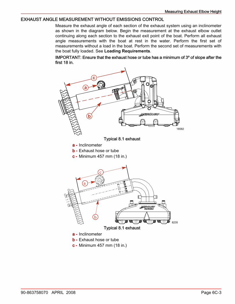
EXHAUST ANGLE MEASUREMENT WITHOUT EMISSIONS CONTROLMeasure the exhaust angle of each section of the exhaust system using an inclinometeras shown in the diagram below. Begin the measurement at the exhaust elbow outletcontinuing along each section to the exhaust exit point of the boat. Perform all exhaustangle measurements with the boat at rest in the water. Perform the first set ofmeasurements without a load in the boat. Perform the second set of measurements withthe boat fully loaded. See Loading Requirements.IMPORTANT: Ensure that the exhaust hose or tube has a minimum of 3º of slope after thefirst 18 in.
a
b
c
18582
Typical 8.1 exhausta - Inclinometerb - Exhaust hose or tubec - Minimum 457 mm (18 in.)
a
b8235
c
Typical 8.1 exhausta - Inclinometerb - Exhaust hose or tubec - Minimum 457 mm (18 in.)
Measuring Exhaust Elbow Height
Page 6C-4 90-863758070 APRIL 2008
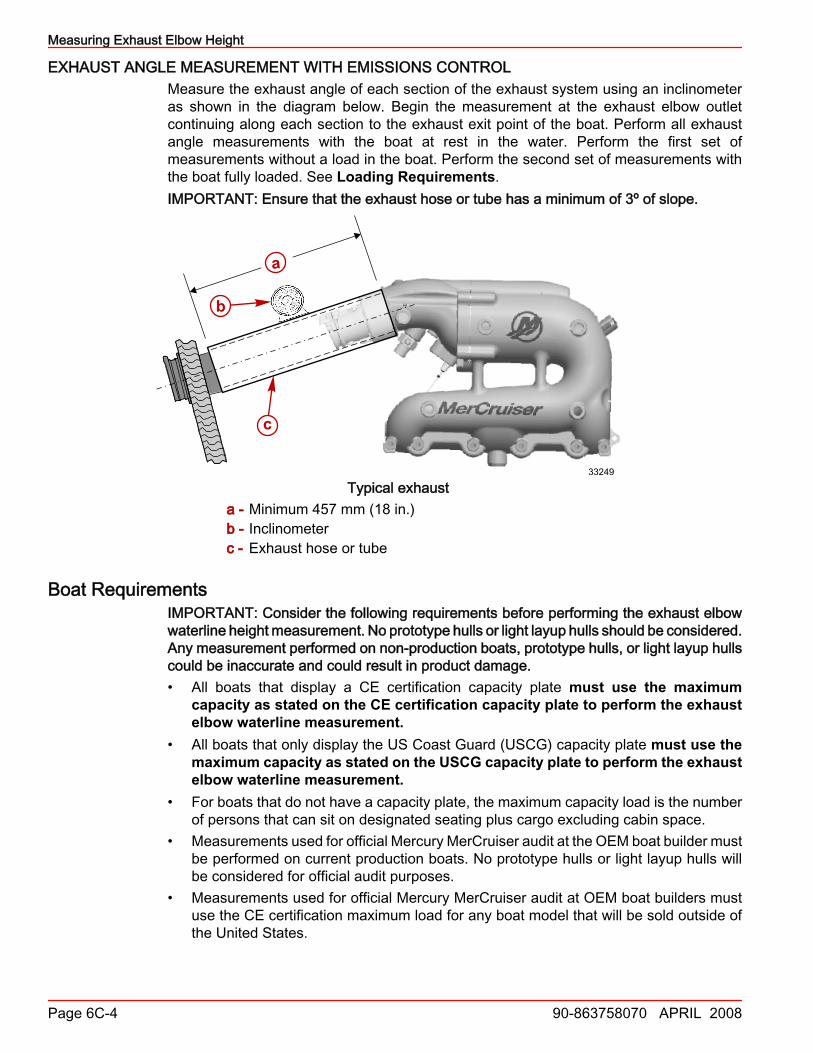
EXHAUST ANGLE MEASUREMENT WITH EMISSIONS CONTROLMeasure the exhaust angle of each section of the exhaust system using an inclinometeras shown in the diagram below. Begin the measurement at the exhaust elbow outletcontinuing along each section to the exhaust exit point of the boat. Perform all exhaustangle measurements with the boat at rest in the water. Perform the first set ofmeasurements without a load in the boat. Perform the second set of measurements withthe boat fully loaded. See Loading Requirements.IMPORTANT: Ensure that the exhaust hose or tube has a minimum of 3º of slope.
b
c
a
33249
Typical exhausta - Minimum 457 mm (18 in.)b - Inclinometerc - Exhaust hose or tube
Boat RequirementsIMPORTANT: Consider the following requirements before performing the exhaust elbowwaterline height measurement. No prototype hulls or light layup hulls should be considered.Any measurement performed on non‑production boats, prototype hulls, or light layup hullscould be inaccurate and could result in product damage.• All boats that display a CE certification capacity plate must use the maximum
capacity as stated on the CE certification capacity plate to perform the exhaustelbow waterline measurement.
• All boats that only display the US Coast Guard (USCG) capacity plate must use themaximum capacity as stated on the USCG capacity plate to perform the exhaustelbow waterline measurement.
• For boats that do not have a capacity plate, the maximum capacity load is the numberof persons that can sit on designated seating plus cargo excluding cabin space.
• Measurements used for official Mercury MerCruiser audit at the OEM boat builder mustbe performed on current production boats. No prototype hulls or light layup hulls willbe considered for official audit purposes.
• Measurements used for official Mercury MerCruiser audit at OEM boat builders mustuse the CE certification maximum load for any boat model that will be sold outside ofthe United States.
Measuring Exhaust Elbow Height
90-863758070 APRIL 2008 Page 6C-5
Loading Requirements1. Fill the fuel tanks, fresh water tanks or holding tanks, ballast tanks, and heater tanks
to simulate fully loaded condition.2. Weights can be used to simulate these load conditions if desired. Place weights in the
corresponding area for which the load is being replaced. Refer to the followingconversions.• 1 U.S. gallon of water = 8.3 lb.• 1 liter of water = 1 kg• 1 U.S. gallon of gasoline = 6 lb.• 1 liter of gasoline = 0.72 kg
3. For the purpose of MerCruiser waterline height measurements:• One person is equivalent to 74.84 kg (165 lb.)• Cargo per person is equivalent to 11.34 kg (25 lb.)
4. Add weight for any additional boat options: extra battery, battery charger, tower, arch,generator, ballast tanks, ballast sacks, television, carpet, anchor, stereo/entertainmentequipment, washer/dryer, safe, etc.
5. If a swim platform is an option, the swim platform must be installed for the waterlineheight measurement. Use the following guide to determine the correct swim platformload:a. Boats less than 8.84 m (29 ft.) long, not including boats that are 8.84 m (29 ft.)
long, must add the maximum rated swim platform weight capacity to the swimplatform.
b. Boats less than 8.84 m (29 ft.) long, not including boats that are 8.84 m (29 ft.)long that do not have a maximum rated swim platform weight capacity, mustadd181.45 Kg (400 lb.) to the swim platform .
c. Boats 8.84 m (29 ft.) long and greater than 8.84 m (29 ft.) long, must add themaximum rated swim platform weight capacity to the swim platform.
d. Boats 8.84 m (29 ft.) long and greater than 8.84 m (29 ft.) long, that do not havea maximum rated swim platform weight capacity must add 226.80 kg (500 lb.) tothe swim platform.
Loading the Boat with a Capacity PlateFor boats with a capacity plate, use the maximum load for persons and gear as listed onthe capacity plate to determine the number of persons to place onto the boat for exhaustelbow waterline height measurements.IMPORTANT: Use 20 inches for average passenger seat width when measuring benchseating. Round up or down at 0.5 to obtain a whole person. See the examples listed below.• 48 in. (bench seat length) ÷ 20 in. (seat width) = 2.4 persons. 2.4 persons rounded
down = 2 persons.• 55 in. (bench seat length) ÷ 20 in. (seat width) = 2.75 persons. 2.75 persons rounded
up = 3 persons.1. Take the maximum capacity weight as listed on the capacity plate (XXXX lb. Persons,
Gear) and subtract the swim platform load, if applicable.2. Next divide the weight by 74.84 kg (165 lb.) per person. This gives the whole number
and remainder of 74.84 kg (165 lb.) persons to load onto the boat.

Measuring Exhaust Elbow Height
Page 6C-6 90-863758070 APRIL 2008
3. Put the remainder of a person in the next available seat. See Boat loading diagram.
2486024861
CE Capacity Plate USCG Capacity PlateIMPORTANT: If there is not enough seating for the number of people, treat the leftoverweight as cargo. Load cargo weight onto the boat before loading passenger weight.4. If applicable, load cargo (leftover persons weight) onto the boat. Distribute cargo as
described below.IMPORTANT: If the boat configuration does not allow for aft, center, and bow storage,choose the storage application from the Optional Cargo Distribution table that best appliesto your boat configuration.
Preferred Cargo DistributionAft storage Center storage Bow storage
25% 50% 25%
Optional Cargo DistributionAft storage Center storage Bow storage
25% 75% NoneNone 75% 25%50% None 50%None 100% None100% None NoneNone None 100%
5. Perform the first measurement with the swim platform loaded and the person takingthe waterline measurement on the boat.
6. Load the swim platform if equipped.7. Measure the exhaust elbow waterline height.IMPORTANT: View all boat seating as rows that are parallel to the transom of the boat.8. Load a person weight into a seat, and measure the exhaust elbow waterline height after
each person weight is loaded onto the boat. Repeat until a person weight is is loadedinto each seat in that row.
9. Continue the process moving forward toward the bow of the boat to the next row ofseats until a person weight is loaded into each seat.
NOTE: The total weight loaded onto the boat must not exceed the maximum capacitydisplayed on the capacity plate.NOTE: The following example is provided as a reference.
EXAMPLENOTE: This example uses a boat that is less than 8.84 m (29 ft.) long, not including a boatthat is 8.84 m (29 ft.) long that does not have a maximum rated swim platform weightcapacity, and must add 181.45 Kg (400 lb.) to the swim platform
Measuring Exhaust Elbow Height
90-863758070 APRIL 2008 Page 6C-7
NOTE: Use 0.50 lb. as the break point to round up or down to obtain a whole pound.1. Maximum load (persons and gear) from capacity plate – swim platform load = remaining
weight to be placed in the boat.• 1100 lb. – 400 lb. = 700 lb.
2. Remaining weight to be placed in the boat ÷ MerCruiser person weight = number ofpersons to load onto the boat• 700 lb. ÷ 165 lb. = 4.24 persons
3. Total number of persons – number of whole persons = remaining persons• 4.24 persons – 4 persons = 0.24 remaining persons
4. Remainder persons ÷ MerCruiser person weight = remainder MerCruiser personweight• 0.24 × 165 lb. = 40 lb.
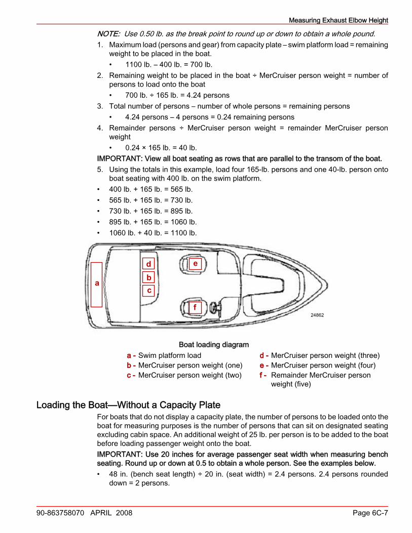
IMPORTANT: View all boat seating as rows that are parallel to the transom of the boat.5. Using the totals in this example, load four 165‑lb. persons and one 40‑lb. person onto
boat seating with 400 lb. on the swim platform.• 400 lb. + 165 lb. = 565 lb.• 565 lb. + 165 lb. = 730 lb.• 730 lb. + 165 lb. = 895 lb.• 895 lb. + 165 lb. = 1060 lb.• 1060 lb. + 40 lb. = 1100 lb.
a
dbc
e
f24862
Boat loading diagrama - Swim platform loadb - MerCruiser person weight (one)c - MerCruiser person weight (two)
d - MerCruiser person weight (three)e - MerCruiser person weight (four)f - Remainder MerCruiser person
weight (five)
Loading the Boat—Without a Capacity PlateFor boats that do not display a capacity plate, the number of persons to be loaded onto theboat for measuring purposes is the number of persons that can sit on designated seatingexcluding cabin space. An additional weight of 25 lb. per person is to be added to the boatbefore loading passenger weight onto the boat.IMPORTANT: Use 20 inches for average passenger seat width when measuring benchseating. Round up or down at 0.5 to obtain a whole person. See the examples below.• 48 in. (bench seat length) ÷ 20 in. (seat width) = 2.4 persons. 2.4 persons rounded
down = 2 persons.
Measuring Exhaust Elbow Height
Page 6C-8 90-863758070 APRIL 2008
• 55 in. (bench seat length) ÷ 20 in. (seat width) = 2.75 persons. 2.75 persons roundedup = 3 persons.
1. Total number of persons that can sit on designated seating excluding cabin space ×MerCruiser person weight = maximum passenger load for measurement.• Number of persons × 165 lb. (MerCruiser person weight) = XXXX lb. maximum
passenger load.2. Maximum passenger load from the calculation above – swim platform load if applicable.3. Divide the weight by 165 lb. per person. This gives the number of 165‑lb. persons to
load onto the boat. Round up to next whole number. See Example 3.IMPORTANT: To account for cargo, add a weight of 25 lb. per person to the boat beforeloading passenger weight onto the boat.4. Calculate the cargo by multiplying 25 lb. by the number of persons that can sit on
designated seating excluding cabin space. See Example.5. Load the cargo onto the boat. Distribute cargo as described below.IMPORTANT: If the boat configuration does not allow for aft, center, and bow storage,choose the storage application from the Optional Cargo Distribution table that best appliesto your boat configuration.
Preferred Cargo DistributionAft storage Center storage Bow storage
25% 50% 25%
Optional Cargo DistributionAft storage Center storage Bow storage
25% 75% NoneNone 75% 25%50% None 50%None 100% None100% None NoneNone None 100%
6. Perform the first measurement with the swim platform loaded and the personmeasuring the waterline on the boat.
7. Load the swim platform if equipped.8. Measure the exhaust elbow waterline height.IMPORTANT: View all boat seating as rows that are parallel to the transom of the boat.9. Load a person weight into a seat, and measure the exhaust elbow waterline height after
each person weight is loaded onto the boat. Repeat until a person weight is is loadedinto each seat in that row.
10. Continue the process moving forward toward the bow of the boat to the next row ofseats until a person weight is loaded into each seat.
EXAMPLENOTE: The following example is provided as a reference.This example uses a boat that is 8.84 m (29 ft.) long and greater than 8.84 m (29 ft.) long,that does not have a maximum rated swim platform weight capacity, and must add226.80 Kg (500 lb.) to the swim platform .

Measuring Exhaust Elbow Height
90-863758070 APRIL 2008 Page 6C-9
IMPORTANT: The Designated Seating Diagram following illustrates the number ofpassengers that can sit on designated seating excluding cabin space.
24863
12
3
4
5
7
8
6 9
Designated Seating DiagramThis example uses 9 persons as the maximum passenger load.NOTE: Use 0.50 lb. as the break point to round up or down to obtain a whole pound.1. To determine the maximum cargo load multiply the maximum passenger load by the
maximum cargo weight per passenger.• 9 passengers × 25 lb. = 225 lb.
2. To determine the preferred cargo distribution for aft, center, and bow storage:a. To determine the maximum aft storage cargo weight, multiply the maximum cargo
weight by 25%3. To determine the maximum center storage cargo weight, multiply the maximum cargo
weight by 50%a. 225 lb. × 50% = 112.50 lb.b. 112.50 lb. rounded up = 113 lb.
4. To determine the maximum bow storage cargo weight, multiply the maximum cargoweight by 25%• 225 lb. × 25% = 56.25 lb.• 56.25 lb. rounded down = 56 lb.
5. To determine the maximum number of passengers to load onto the boat, multiply 9passengers by 165 lb. (MerCruiser person weight) to get a 1485 lb. (total passengerload)• 9 passengers × 165 lb. = 1485 lb.
6. Subtract the swim platform load from the total passenger load to get the remainingweight to be placed in the boat.• 1485 lb. – 500 lb. = 985 lb.
7. Divide the remaining weight to be placed onto the boat by the MerCruiser person weightto get the maximum number of passengers to load onto the boat.• 985 lb. ÷ 165 lb. = 5.9 passengers• 5.90 passengers rounded up = 6 passengers
8. Using the totals in this example load 56 lb. cargo in the aft storage, 113 lb. cargo in thecenter storage, and 56 lb. cargo in the bow storage onto the boat before addingpassenger weight. Then, load six 165 lb. passengers, onto the boat with 500 lb. on theswim platform.
• 500 lb. + 225 lb. = 725 lb.• 725 lb. + 165 lb. = 890 lb.• 890 lb. + 165 lb. = 1055 lb.

Measuring Exhaust Elbow Height
Page 6C-10 90-863758070 APRIL 2008
• 1055 lb. + 165 lb. = 1220 lb.• 1220 lb. + 165 lb. = 1385 lb.• 1385 lb. + 165 lb. = 1550 lb.• 1550 lb. + 165 lb. = 1715 lb.
a cbd
h e
f
g
i j
24864
Cargo, swim platform, and passenger weight loading diagrama - Swim platform loadb - MerCruiser person weight (one)c - MerCruiser person weight (two)d - MerCruiser person weight (three)e - MerCruiser person weight (four)
f - MerCruiser person weight (five)g - MerCruiser person weight (six)h - Aft storagei - Center storagej - Bow storage
Clear Hose Measurement Method1. Obtain an 8–10 mm (5/16–3/8 in.) ID (inner diameter) clear hose approximately 4.5 m
(15 ft.) long. Install a metal fitting or a weight on one end of the hose to keep that endof the hose below the waterline. The fitting or weight must not restrict water from fillingthe clear hose.
24865
a
b
b
c
a - Clear hoseb - Fittingc - Unrestricted opening
IMPORTANT: On engines equipped with more than one exhaust elbow, perform theexhaust elbow waterline height measurement on the side that sits lowest in the water.2. Put the weighted end of the clear hose over the side of the boat that is sitting lowest in
the water.3. Submerge the clear hose until completely filled with water.4. Place a finger over the open end of the clear hose before removing it from the water.
Measuring Exhaust Elbow Height
90-863758070 APRIL 2008 Page 6C-11
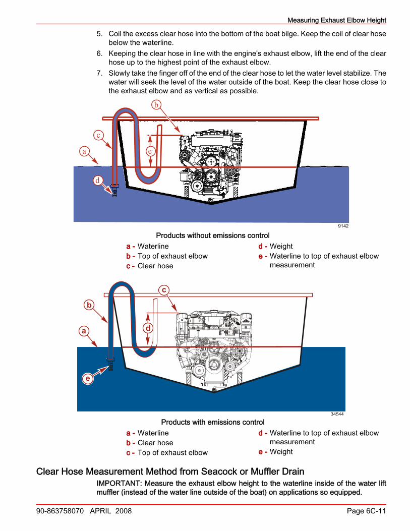
5. Coil the excess clear hose into the bottom of the boat bilge. Keep the coil of clear hosebelow the waterline.
6. Keeping the clear hose in line with the engine's exhaust elbow, lift the end of the clearhose up to the highest point of the exhaust elbow.
7. Slowly take the finger off of the end of the clear hose to let the water level stabilize. Thewater will seek the level of the water outside of the boat. Keep the clear hose close tothe exhaust elbow and as vertical as possible.
b
c
a
8340
e
d
9142
Products without emissions controla - Waterlineb - Top of exhaust elbowc - Clear hose
d - Weighte - Waterline to top of exhaust elbow
measurement
c
e
a
b
d
34544
Products with emissions controla - Waterlineb - Clear hosec - Top of exhaust elbow
d - Waterline to top of exhaust elbowmeasurement
e - Weight
Clear Hose Measurement Method from Seacock or Muffler DrainIMPORTANT: Measure the exhaust elbow height to the waterline inside of the water liftmuffler (instead of the water line outside of the boat) on applications so equipped.

Measuring Exhaust Elbow Height
Page 6C-12 90-863758070 APRIL 2008
IMPORTANT: The engine must have been operated previously to fill the muffler with water.IMPORTANT: On engines equipped with more than one exhaust elbow, perform theexhaust elbow waterline height measurement on the side that sits lower in the water.1. Attach a clear hose to the muffler drain point or seacock drain point.2. Start the engine to fill the muffler and hose.3. If attached to the seacock drain, open the seacock.4. Route the remainder of the hose toward the engine's exhaust manifold and elbow.
Ensure that this open end section of the hose is as vertical as possible from the boat'sbilge to the top of the exhaust elbow.
5. Coil excess hose in the bilge of the boat, keeping it below the water line.6. Lower the open end of the hose and siphon water until it starts to come out of the hose.
Put a finger over the hose and lift open end until it is at the top of the exhaust elbow.7. Slowly take the finger off of the end of the hose to let the water level stabilize. The water
will seek the level of the water outside the boat. Keep the hose close to the exhaustelbow and as vertical as possible.
8. The measurement between the water in the hose and the top of the exhaust elbow isthe exhaust elbow height. The maximum riser height is 20.3 cm (8 in.) on 8.1 H.O. andHorizon 8.1 models with and without emissions control. Riser height is limited to15.2 cm (6 in.) on all 5.7 and 6.2 models without emissions control and 20.3 cm (8 in.)on all 5.7 models with emissions control.
NOTE: Measure the water line inside the muffler when the drain plug is not available.PRODUCTS WITHOUT EMISSIONS CONTROL
a
b24866
Typical vertical water lift mufflera - Minimum exhaust elbow height with maximum loadb - Clear hose for measuring waterline
Measuring Exhaust Elbow Height
90-863758070 APRIL 2008 Page 6C-13
a
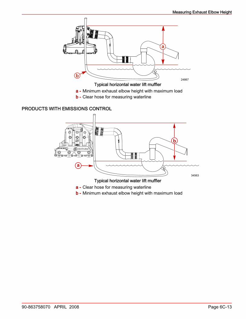
b24867
Typical horizontal water lift mufflera - Minimum exhaust elbow height with maximum loadb - Clear hose for measuring waterline
PRODUCTS WITH EMISSIONS CONTROL
b
a
34563
Typical horizontal water lift mufflera - Clear hose for measuring waterlineb - Minimum exhaust elbow height with maximum load

Measuring Exhaust Elbow Height
Page 6C-14 90-863758070 APRIL 2008
a
b
34562
Typical vertical water lift mufflera - Clear hose for measuring waterlineb - Minimum exhaust elbow height with maximum load
Measurement Method without Seacock or Muffler DrainIMPORTANT: Measure the exhaust elbow height to the waterline inside of the water liftmuffler (instead of the water line outside of the boat) on applications so equipped.IMPORTANT: The engine must have been operated previously to fill the muffler with water.IMPORTANT: On engines equipped with more than one exhaust elbow, perform theexhaust elbow waterline height measurement on the side that sits lowest in the water.1. Remove the the discharge hose from the waterlift muffler.2. Measure the water level inside the muffler.3. Mark the outside of the muffler to show the water line height inside the muffler.4. Using an appropriate tool measure the distance from the muffler waterline to the top of
the exhaust elbow to determine the exhaust elbow height.