exhibit 3.2.2 patrick engineering 345 kv …yosemite.epa.gov/oa/eab_web_docket.nsf/filings by appeal...
TRANSCRIPT
Exhibit 3.2.2
Patrick Engineering 345 kV Transmission Line Conceptual Design and Project Estimate


300 West Edwards Street, Suite 200, Springfield, Illinois 62704 | 800.799.7050 | patrickengineering.com
Taylorville 345kV Transmission Line
Conceptual Design & Project Estimate
Prepared For
December 18, 2009
Prepared By
Patrick Engineering Inc.
Project # 20903.038


Table of Contents INTRODUCTION 1
PROJECT DESCRIPTION 1
ASSUMPTIONS 1
CONCEPTUAL LINE DESIGN 2
FINAL TRANSMISSION LINE ENGINEERING 3
AERIAL SURVEY 4
SITE SURVEY 5
GEOTECHNICAL SERVICES 5
MATERIAL SUPPLIERS 6
CONSTRUCTION SERVICES 6
EPC PROJECT MANAGEMENT 7
COST SUMMARY 7
CONCLUSION 8
Appendices
Transmission Line Study A
Local Transmission Utility Design Standards B
Conceptual Line Design C
Aerial Survey D
Site Survey E
Geotechnical Services F
Material Suppliers G
Construction H
EPC Project Management J


Tenaska 345kV Transmission Line Page 1 of 8
Taylorville 345kV Transmission Line
Conceptual Design & Project Estimate
INTRODUCTION
Patrick Energy Services (Patrick) conducted a preliminary engineering study to develop a conceptual design for the proposed route of a 345kV transmission line extending from the Taylorville Energy Center to a local transmission utility’s existing Kincaid substation. This report includes a general description of the project, the assumptions made during engineering, and a detailed description of the preliminary design developed during this project. There is also an opinion of probable cost for the project included with this study which identifies specific subcontractor activities and the associated costs for each.
PROJECT DESCRIPTION
The purpose of this project is to develop a conceptual design and provide opinion of probable costs to Tenaska in order to prepare a project cost estimate. The proposed 345kV transmission line starts at the dead end structure of the Taylorville Energy Center to the fence of Kincaid Substation. The line will be designed to support two circuits but only one circuit will be installed for this study. The line will cross over privately owned properties as well as lakes and highways. The line will skirt the cities of Bulpitt, Tovey, and Taylorville, IL. Tenaska has requested Patrick to provide a +/- 30% cost estimate for the complete project. The proposed line route was selected by Tenaska from a previous study performed by Patrick. The study is attached to this report in Appendix A. The line study performed evaluated various transmission line routes from the Taylorville Energy Center to the Kincaid substation. After studying the options, Patrick developed three proposed routes and an additional connection route. Tenaska selected a combination of the North and Direct routes connected by the Alternate route. Patrick and Tenaska agreed that the combined route impacted the least amount of residents. Appendix A includes a map of the various options along with a map of the final route.
ASSUMPTIONS Some notable assumptions were made during the preliminary engineering of this line. Descriptions of these are listed here:
• Conceptual Design – The contents of this report are for conceptual and budgetary purposes only and are not intended to be used for final design purposes.
• Local transmission utility Standards – Structure type, conductor and shield wire types as well as stringing strength and ruling spans conform to local transmission utility standards.

Tenaska 345kV Transmission Line Page 2 of 8
• Land Acquisition – Land Acquisition was not included as part of this project. Tenaska will be providing land acquisition services for both permanent and construction services. A value of $332 per rod was supplied by Tenaska for 150ft wide right of way and multiplied by the 14 mile line to arrive at lump sum price located in the project cost summary.
• Wetland Delineation – Tenaska has already preformed some wetland studies in the region for other projects and will perform similar studies for transmission line activities.
CONCEPTUAL LINE DESIGN
Patrick performed the conceptual line design with Tenaska’s direction. A picture of final line route can be seen in Appendix C. The proposed line utilizes local transmission utility standards. The standards referenced can be found in Appendix B. Patrick created plan and profile drawings which are located in Appendix C. Patrick designed single pole steel structures to support the double circuit line. The tangent structure used is Transmission Overhead Material specification number EM10561. Patrick used dead end specification number EM10566. Both of the specifications are located in Appendix B. At this time, not all the individual angle structures were modeled but this will be completed in a final design. The structures were modeled in Power Line Systems’ PLS Pole, a design software to design poles and attach equipment that can later be placed in a working model for ultimate design purposes. The poles were designed to a height of 115 feet from ground level to top of structure. They were then height adjusted as needed in the model. For the tangent structure the top arm has a length of 26 feet and secures the shield wire and top phase. The lower two arms are 16.5 feet in length, each supporting a single phase. For the dead end structure the top arm has a length of 30 feet and secures the shield wire. The lower three arms are 19 feet in length, each supporting a single phase. Conductors were selected per local utility’s standards Table III in EM10561. The conductor selected was a T2 BlueJay. The T2 conductor represents a twisted pair of standard BlueJay conductors. This conductor type reduces effects from galloping in the conductors. Galloping is an oscillation due to wind in the conductors that causes more stress on the transmission line and is prevalent in this area of the country. Patrick performed a three phase power equation to calculate the ampacity of the line to ensure it would be sufficient for Tenaska’s needs. This calculation can be seen in Appendix C. The conductor information can be found in specification EM28061 which can be found in Appendix B. This appendix describes the physical attributes as well as the blowout characteristics of the conductor. As part of this study Patrick investigated the blowout of this conductor to determine the right of way width needed. The drawbacks of this conductor are increased cost for the construction company to string the conductor, increased material needs, and it has limited availability. This is due to the twisted multi conductor design. The shield wire proposed is a 24 fiber optical ground wire. The shield wire attribute information can be found in specification EM28062. Patrick recommends the use of fiber optics in this situation due to increasing demands for communication on transmission lines.
Tenaska 345kV Transmission Line Page 3 of 8
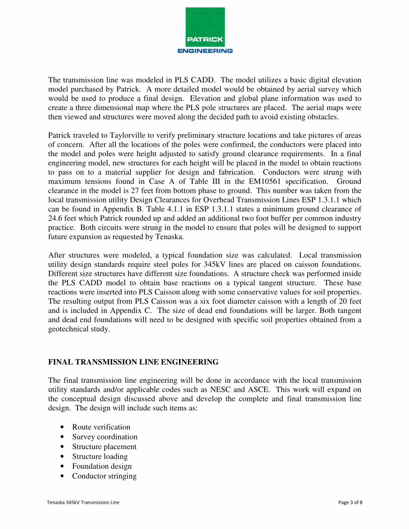
The transmission line was modeled in PLS CADD. The model utilizes a basic digital elevation model purchased by Patrick. A more detailed model would be obtained by aerial survey which would be used to produce a final design. Elevation and global plane information was used to create a three dimensional map where the PLS pole structures are placed. The aerial maps were then viewed and structures were moved along the decided path to avoid existing obstacles. Patrick traveled to Taylorville to verify preliminary structure locations and take pictures of areas of concern. After all the locations of the poles were confirmed, the conductors were placed into the model and poles were height adjusted to satisfy ground clearance requirements. In a final engineering model, new structures for each height will be placed in the model to obtain reactions to pass on to a material supplier for design and fabrication. Conductors were strung with maximum tensions found in Case A of Table III in the EM10561 specification. Ground clearance in the model is 27 feet from bottom phase to ground. This number was taken from the local transmission utility Design Clearances for Overhead Transmission Lines ESP 1.3.1.1 which can be found in Appendix B. Table 4.1.1 in ESP 1.3.1.1 states a minimum ground clearance of 24.6 feet which Patrick rounded up and added an additional two foot buffer per common industry practice. Both circuits were strung in the model to ensure that poles will be designed to support future expansion as requested by Tenaska. After structures were modeled, a typical foundation size was calculated. Local transmission utility design standards require steel poles for 345kV lines are placed on caisson foundations. Different size structures have different size foundations. A structure check was performed inside the PLS CADD model to obtain base reactions on a typical tangent structure. These base reactions were inserted into PLS Caisson along with some conservative values for soil properties. The resulting output from PLS Caisson was a six foot diameter caisson with a length of 20 feet and is included in Appendix C. The size of dead end foundations will be larger. Both tangent and dead end foundations will need to be designed with specific soil properties obtained from a geotechnical study.
FINAL TRANSMISSION LINE ENGINEERING The final transmission line engineering will be done in accordance with the local transmission utility standards and/or applicable codes such as NESC and ASCE. This work will expand on the conceptual design discussed above and develop the complete and final transmission line design. The design will include such items as:
• Route verification
• Survey coordination
• Structure placement
• Structure loading
• Foundation design
• Conductor stringing
Tenaska 345kV Transmission Line Page 4 of 8
• Material selection
• Permit coordination
• Construction coordination
• Project close out including as-builts Engineering deliverables would include:
• Stringing charts
• Staking reports
• Specifications o Material procurement o Construction o Geotechnical
• Bill of materials
• Drawings o Structure load and design o Plan and profile o Hardware assemblies
Patrick has developed an estimate to complete this design. A spreadsheet outlining Patrick’s anticipated hours to be spent on final engineering activities for this project can be found in Appendix C. This estimate incorporates all tasks and deliverables mentioned above. It also includes time and expenses for meeting attendance, phone conferences, site visits, and contacting and supporting other subcontractors. Anticipated site visits would include; initial route walk down, follow up review of areas that require special considerations, and verification of staking locations. The total project cost for this can be found in the cost summary of this document.
AERIAL SURVEY
Various companies were contacted to provide estimates for aerial survey and topographic mapping activities for the final engineering. An aerial survey company will provide color digital imagery of line area and data files for PLS model production. The current survey map used for PLS CADD model is accurate enough for proposals but the data is spread out and of a general variety. It is important when designing large expensive structures that the information used is as accurate as possible because small discrepancies can result in expensive redesign. Two different methods to produce this survey information are Photogrammetry and Lidar. Photogrammetry is a method of obtaining topographic information using aerial photograph to develop terrain information. Lidar is a traditional method for collecting topographic information using a laser to scan the area to produce point coordinates. Both technologies have the ability to develop elevation contours in one foot intervals. They take the collected data and convert it into

Tenaska 345kV Transmission Line Page 5 of 8
a format that can be placed into a PLS CADD model. It also separates out the different ground points into various features such as vegetation, roads, ground features, and bodies of water. There are many other features that can be collected by aerial survey companies which can be viewed in Appendix D. Some of these features include taking video of the route, taking still pictures of structures in the line area, converting data to a GIS format and many other services. Approximate price for aerial survey can be seen in the cost summary. The final number used was produced using the highest budgetary estimate to be conservative. We feel that the budgetary estimate submitted by the contractor is applicable to this work scope.
SITE SURVEY
Site survey is another necessary activity of design and construction of the final transmission line. Survey activities will include:
• Real-estate investigation
• Survey and determine property lines & owners
• New easement exhibits for the owners
• Verification of aerial obstacles
• Staking activities for the right of way as well as two occasions of construction staking Various companies were contacted to provide budgetary estimates for site survey activities which can be seen in Appendix E. The approximate price for site survey can be seen in the cost summary. To be conservative the highest budgetary estimate was used.
GEOTECHNICAL SERVICES
Various companies were contacted to provide estimates for soil boring and soil lab activities. It is important to perform testing on soils in the location of each structure because soil conditions vary from location to location. Different locations will show different conditions over the 14 mile line and a foundation could be sufficient for one location and not for another. Standard practice is to obtain a general condition that works for a majority of the tangent structures and custom design the dead end foundations and other outliers. To obtain estimates, contractors were asked to estimate costs of approximately 100 soil borings to a depth of 50 feet or refusal. The typical foundation depth will not be greater than 30 feet, but deeper foundations will be utilized at dead end locations. The contractors were asked to include all associated cost with producing a geotechnical report of the encountered conditions and provide foundation recommendations.

Tenaska 345kV Transmission Line Page 6 of 8
Subcontractors were informed that all locations would be staked, cleared and that access approvals would be provided to perform work. The estimates we received covered a wide range therefore a calculated cost was derived by averaging the highest two estimates to be conservative. Adjustments can be made to the scope of soil study such as soil borings can be taken at less frequent intervals to cut costs. The approximate price for geotechnical services is included in the cost summary.
MATERIAL SUPPLIERS
Various companies were contacted to provide estimates for total material cost. The materials included in these estimates are conductors, optical shield wire, poles, grounding, insulators, and other hardware. It is important to note that prices of these items will fluctuate, especially the steel poles. Materials also vary by when delivery is needed. Prices in this section reflect a projected value of steel for mid 2010 with an average delivery time, approximately 20 weeks. The most significant cost will be the steel poles. The estimated cost is shown in the cost summary. This cost has been divided into two values due to the significance of the cost of the steel poles. The steel poles have been shown independently and other materials are combined into a material category. Some specific material details can be found in Appendix G. From the estimates we received, one contractor appeared to have the best understanding of the needs for this project. Therefore, their value was used for all hardware. For steel poles a cost was averaged from suppliers with similar estimates.
CONSTRUCTION SERVICES
Various companies were contacted to provide estimates for construction services. Construction activities are as follows:
• Unloading and storage of materials
• Constructing foundations
• Framing poles
• Setting poles
• Pull/string conductor
• Restoration of area Included with construction costs is the clearing cost. Patrick contacted clearing subcontractors and obtained a cost of clearing from two different contractors. The right of way must be cleared for various reasons, one of the most important being electrical clearance. Trees represent hazards to the transmission line. Construction, surveying, and soil boring activities are all greatly impeded by non cleared locations.

Tenaska 345kV Transmission Line Page 7 of 8
Construction costs will differ depending on soil conditions and structure size. Poor soil conditions will result in larger foundations. Large structure sizes result in larger foundations as well as added difficulty in placement. Some contractors have broken up estimates for specific activities such as pole framing and pole setting while other contractors elected to submit an estimate as a cost per mile of construction. Approximate price for construction services can be seen on the cost summary. In determining the final budgetary estimate one contractor was abnormally low and was therefore not included in our determination. The remaining two contractors’ numbers were similar and were averaged and combined with the clearing cost.
EPC PROJECT MANAGEMENT
Project management for this project consists of working with all parties communicating Tenaska’s needs. The engineer will purchase required materials and contract the subcontractors. Project management would also develop and maintain a construction schedule. The estimated total time to complete this project is 24 to 30 months. One of the most critical tasks is ordering the materials. The lead time on steel poles alone is approximately 20 weeks. Other crucial tasks include aerial and site survey because they need to be completed before most of the engineering can be done. The anticipated construction schedule can be seen in Appendix J. The total cost of this activity is a percentage of the various project activities and can be viewed in the project cost summary.
PROJECT COST SUMMARY
December 2009
Overnight Cost Estimate
Subcontractor Category Total Price
Land Acquisition $1,487,360
Engineering $1,049,360
Lidar/Aerial Survey $34,145
Site Survey $169,940
Geotechnical Services $150,000
Steel Poles $6,124,980
Other Materials $1,789,255
Construction $10,800,000
EPC Project Management $2,055,570
Total $23,660,610

Tenaska 345kV Transmission Line Page 8 of 8
CONCLUSION
Patrick has concluded that the route proposed by Tenaska is a viable route. After conducting a conceptual study Patrick has developed a conceptual design that incorporates 98 structures over the 14 mile line. Utilizing local transmission utility standards, Patrick collected required information and distributed it to various subcontractors in an effort to achieve a budget estimate within 30% accuracy. The approximate cost for this project is estimated at $23,660,610. The following pages contain the appendices referenced in this section. Any questions about this report or the line design should be directed to Patrick Engineering.
Patrick Engineering Inc.
Christopher P. Dietzler, P.E. Vice President

Tenaska 345kV Transmission Line
Appendix A
Tenaska Transmission Line Study


Tenaska 345kV Transmission Line
Appendix B
Local Transmission Utility Design Standards


Tenaska 345kV Transmission Line
Appendix C
Conceptual Line Design


PLS-CADD Drawing
-250 0
250
500
750
1000
1250
1500
1750
2000
2250
2500
2750
3000
3250
3500
3750
4000
4250
4500
4750
5000
5250
5500
5750
6000
6250
6500
6750
7000
550
600
650
700
750
800
850
900
950
550
600
650
700
750
800
850
900
950
PI
0°00'0
0"
PI
-20°30'2
0"
PI
19°59'5
1"
1 1
15-6
0-9
0de-3
86478.p
ol
sta
=0.0
0ht=
125.0
0 e
le=
604.0
0ht
adju
st=
10.0
0386270
2 1
15-t
angent-
386270.p
ol
sta
=578.9
9ht=
125.0
0 e
le=
606.0
0ht
adju
st=
10.0
0386270
3 1
15-6
0-9
0de-3
86478.p
ol
sta
=1213.2
3ht=
125.0
0 e
le=
602.8
8ht
adju
st=
10.0
0386270
4 1
15-6
0-9
0de-3
86478.p
ol
sta
=1996.9
3ht=
135.0
0 e
le=
600.4
6ht
adju
st=
20.0
0386270
5 1
15-t
angent-
386270.p
ol
sta
=2811.5
4ht=
135.0
0 e
le=
593.0
1ht
adju
st=
20.0
0386270
6 1
15-t
angent-
386270.p
ol
sta
=3619.0
5ht=
135.0
0 e
le=
593.4
5ht
adju
st=
20.0
0386270
7 1
15-t
angent-
386270.p
ol
sta
=4432.3
0ht=
130.0
0 e
le=
593.9
0ht
adju
st=
15.0
0386270
8 1
15-t
angent-
386270.p
ol
sta
=5113.8
1ht=
125.0
0 e
le=
594.2
8ht
adju
st=
10.0
0386270
9 1
15-t
angent-
386270.p
ol
sta
=5815.2
4ht=
125.0
0 e
le=
594.6
7ht
adju
st=
10.0
0386270
10 1
15-t
angent-
386270.p
ol
sta
=6522.4
8ht=
125.0
0 e
le=
595.0
6ht
adju
st=
10.0
0386270
578.99 632.02 783.70 814.62807.51 813.24 681.52 701.42 707.24
725.00
1 2 3
4
5 6 7 8 9 10 11
PI
0.0
00°00
'00"
PI 1176.0
0
-20°3
0'2
0"
PI
1996.9
3
19°59'5
1"
10/27/2009Page 1/10
Tenaska 345kV Transmission LinePreliminary Layout
Vert. Scale
Horiz. Scale
100.0 ft.
500.0 ft.
North

PLS-CADD Drawing
7250
7500
7750
8000
8250
8500
8750
9000
9250
9500
9750
10000
10250
10500
10750
11000
11250
11500
11750
12000
12250
12500
12750
13000
13250
13500
13750
14000
14250
14500
550
600
650
700
750
800
850
900
950
550
600
650
700
750
800
850
900
950
PI
-17°36'0
7"
11 1
15-t
angent-
386270.p
ol
sta
=7247.4
8ht=
130.0
0 e
le=
595.4
6ht
adju
st=
15.0
0386270
12 1
15-t
angent-
386270.p
ol
sta
=7972.4
8ht=
125.0
0 e
le=
595.8
6ht
adju
st=
10.0
0386270
13 1
15-t
angent-
386270.p
ol
sta
=8697.4
8ht=
130.0
0 e
le=
596.2
5ht
adju
st=
15.0
0386270
14 1
15-t
angent-
386270.p
ol
sta
=9422.4
8ht=
125.0
0 e
le=
596.6
5ht
adju
st=
10.0
0386270
15 1
15-t
angent-
386270.p
ol
sta
=10147.4
8ht=
130.0
0 e
le=
597.0
5ht
adju
st=
15.0
0386270
16 1
15-t
angent-
386270.p
ol
sta
=10872.4
8ht=
125.0
0 e
le=
597.4
5ht
adju
st=
10.0
0386270
17 1
15-t
angent-
386270.p
ol
sta
=11597.4
8ht=
130.0
0 e
le=
597.8
5ht
adju
st=
15.0
0386270
18 1
15-t
angent-
386270.p
ol
sta
=12322.4
8ht=
125.0
0 e
le=
598.2
5ht
adju
st=
10.0
0386270
19 1
15-t
angent-
386270.p
ol
sta
=13047.4
8ht=
130.0
0 e
le=
598.6
5ht
adju
st=
15.0
0386270
20 1
15-6
0-9
0de-3
86478.p
ol
sta
=13772.4
8ht=
145.0
0 e
le=
597.0
0ht
adju
st=
30.0
0386270
725.00 725.00 725.00 725.00 725.00 725.00 725.00 725.00
725.001052.75
11 12 13 14 15 16 17 18 19 20
PI 13772.4
8
-17°3
6'0
7"
10/27/2009Page 2/10
Tenaska 345kV Transmission LinePreliminary Layout
N 4
30 E
ast R
d.
Vert. Scale
Horiz. Scale
100.0 ft.
500.0 ft.
North