exoflex manual eng - home | regin controls · 8 part i introduction and system overview chapter 2...
TRANSCRIPT

EXOflex Manual
© Copyright AB Regin, Sweden, 2008

DISCLAIMER
The information in this manual has been carefully checked and is believed to be correct. AB Regin however, makes no warranties as regards the contents of this manual and users are requested to report errors, discrepancies or ambiguities to Regin, so that corrections may be made in future editions. The information in this handbook is subject to change without prior notification.
The software described in this book is supplied under license by Regin and may be used or copied only in accordance with the terms of the license. No part of this book may be reproduced or transmitted in any form, in any fashion, electronically or mechanically, without the express, written permission of Regin.
COPYRIGHT
© AB Regin. All rights reserved.
TRADEMARKS
EXOdesigner, EXOreal, EXO4 and EXOline are registered trademarks of AB Regin.
MS-DOS, Windows, Windows 95, Windows 98, Windows 2000 and Windows NT are registered trademarks of Microsoft Corporation.
Echelon, LON, LONWORKS, LonMaker, LonTalk, LNS, LONMARK are registered trademarks of Echelon Corporation
Some product names mentioned in this book are used for identification purposes only and may be the registered trademarks of their respective companies.
January 2008
Document Revision: 2005-1-02
Brief Contents
Part I Introduction and System Overview 5 Chapter 1 Using This Manual 7 Chapter 2 Introduction to EXOflex 8 Chapter 3 EPU Internal System Design 22 Chapter 4 Naming System for EXOflex Components 27
Part II Installation and Commissioning 29 Chapter 5 Cabinet Installations 31 Chapter 6 Power Supply 33 Chapter 7 Communication Buses & Interfaces 36 Chapter 8 Connecting Active Transmitters to Inputs 39 Chapter 9 Commissioning 41
Part III EXOflex Software 43 Chapter 10 Overview 47 Chapter 11 EFX PIFA Units 49 Chapter 12 The Processor and the Power-PIFA 56 Chapter 13 Communication 59 Chapter 14 Digital Inputs 62 Chapter 15 Digital Outputs 67 Chapter 16 Analog Inputs 72 Chapter 17 Analog Outputs 76 Chapter 18 The External Display 79 Chapter 19 TCP/IP 83 Chapter 20 Applications 96
Part IV Specifications 100 Enclosure Specifications 102 Environment Specifications 104 Processor Specifications, ECX1 105 General PIFA Specifications 106 Model Modem 9011 - PTT Modem 113
Part V Examples of Complete EXOflex-units 127
Chapter 21 Complete EXOflex-units 129
Part VI Maintenance and Service 130 Chapter 22 Changing the Battery 132 Chapter 23 Resetting The Program Memory 135

Chapter 24 Changing the PROM 137 Chapter 25 Installing Processors and Option Cards 138
Part VII Appendix 142 Chapter 26 Modems 144 Chapter 27 Options 146 Chapter 28 Interference 150 Chapter 29 The EMC and LVD Directive 152 Chapter 30 Glossary of Terms 153
Part VIII Index 155
Part IX Regin Resellers 160

Chapter 1 Using This Manual 5
PPaarrtt II IInnttrroodduuccttiioonn aanndd SSyysstteemm OOvveerrvviieeww
6 Part I Introduction and System Overview
Table of contents Part I Introduction and System Overview
Chapter 1 Using This Manual 7 Conventions Used in This Manual 7
Chapter 2 Introduction to EXOflex 8 EXOflex 8 EPU – EXO Process Unit 8 The EXOflex Housing 9 The EXOL Processor 11 EXOflex PIFA-units 11 Mounting a PIFA-unit 12 Compact Mounting 12 Signal Descriptions 13
Cardholders 13 Inlay Cards for PIFA-units 14
Mounting 16 Horizontal Rail-mounting 16 Wall Mounting 18 Vertical Mounting 19 External Display 20 Summary 21
Chapter 3 EPU Internal System Design 22 Isolation Barrier 23 Addressing PIFA-units 23 Distributed Processor Power 24 The Built-In Battery 25 Serial Ports 25
Multi-Processor House 26
Chapter 4 Naming System for EXOflex Components 27
Houses (process houses/expansion houses) 27 PIFA-units 27

Chapter 1 Using This Manual 7
Chapter 1 Using This Manual
This manual presents guidelines for system designers and project engineers on how to structure and connect EXOflex-units and other equipment into reliable systems.
This manual is intended as a guide. The final responsibility for the function of any particular installation rests solely upon the system designer, who should, by extensive testing, ensure that all the specifications are met.
If you should find errors or unclear information in this manual, kindly contact Regin so that future editions can be corrected and improved.
This manual will be revised without prior notice, as and when deemed necessary. Please check regularly that you have the latest revision.
Conventions Used in This Manual This manual uses the following conventions:
This box and symbol will provide general information, not necessarily concerned directly with EXOflex.
This box and symbol will provide useful tips and tricks.
This type of box will give important information about avoiding common mistakes, dangerous practices, etc.
This box and symbol will be used to guide you through a procedure.

8 Part I Introduction and System Overview
Chapter 2 Introduction to EXOflex
EXOflex EXOflex is a general system for control, regulation, supervision and communication in general automation installations. The system offers great possibilities when constructing many different types of control and regulation systems: outstations in distributed systems, DUC’s in building automation systems, service gateways in LAN’s and on the Internet, etc.
The system is of a modular design and provides unique opportunities for adapting the number and type of inputs and outputs required, as well as the type of communication needed by the individual client.
An EXOflex unit is a process computer that can run completely independently or linked to other EXOflex-units and other types of computers and equipment, in small or large systems.
EXOflex consists of a range of hardware components, and of comprehensive software in the form of an operating system, standardized applications and add-ons. EXOflex is to a large extent compatible with other EXO products, including older process stations (controllers) and software.
Software applications such as EXOdesigner (development tools), EXO4 (operator program/SCADA), EXOreport etc, can be used to their full extent with EXOflex, and have in some cases been supplemented to fully integrate EXOflex with earlier products.
The software for EXOflex is described in Part III of this book. The system’s hardware is described below.
EPU – EXO Process Unit EXOflex makes it possible to construct process stations with varying types and numbers of I/Os, communication ports and processors. The concept EPU = EXO Process Unit is used to designate an EXOflex process station, and is often equivalent to a Module in the earlier product range (strictly speaking, there are a few differences, which will be described later). The EPU is programmed in the same way, with EXOdesigner and ready-made objects and blocks, or alternatively, in free EXOL-code. The same program can often be used with few or no changes. The processor running the EXOL-code is called the main processor or EXOL processor. In contrast to earlier systems, an EPU can contain several EXOL processors.
An EPU usually consists of a mechanical unit mounted in a house. All the external connections are found on the PIFA = Process Interface Adapter. To increase the number of I/Os, an EPU can be extended with one or more houses, each containing further PIFA-units. These are known as “Expansion Units”.
Most of the PIFA-units have their own microprocessors, which provide specific configurable function for that model. This facilitates programming and reduces the load on the EXOL-processor. This configuration is done in EXOdesigner, in easy-to-use windows.
Chapter 2 Introduction to EXOflex 9
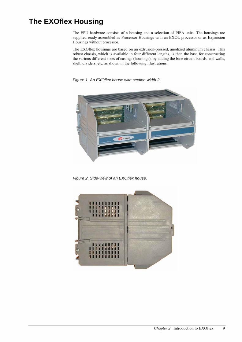
The EXOflex Housing The EPU hardware consists of a housing and a selection of PIFA-units. The housings are supplied ready assembled as Processor Housings with an EXOL processor or as Expansion Housings without processor.
The EXOflex housings are based on an extrusion-pressed, anodized aluminum chassis. This robust chassis, which is available in four different lengths, is then the base for constructing the various different sizes of casings (housings), by adding the base circuit boards, end walls, shell, dividers, etc, as shown in the following illustrations.
Figure 1. An EXOflex house with section width 2.
Figure 2. Side-view of an EXOflex house.

10 Part I Introduction and System Overview
Figure 3. The basic components of an EXOflex house.
Seperator
Covers
Base Circuit Board
End-wall Shell
Extrusion pressed,anodisedaluminium chassis
The basic system encompasses four different sizes of casing, with the section- widths 1, 2, 3 or 4. These are constructed from the components described above, all of which are also available as spare parts.
Figure 4. A complete EXOflex unit.

Chapter 2 Introduction to EXOflex 11
The EXOL Processor The EXOL processor is located on two separate cards.
CPU-card with a C515C micro-controller
EFX-card with C515C micro-controller
These two cards, known as ECX1, are jointly responsible for the processor function and will together be known as the Processor in the rest of this text.
It is also possible, at a later point, to connect the processor function in an expansion unit. See Chapter 25 Installing Processors and Option Cards.
EXOflex PIFA-units The true power of the EXOflex system lies in the range of PIFA-units available. All the cards are of a standard design and size and can be quickly and simply installed by slotting them into place.
Figure 5. An EXOflex PIFA-unit.
Processor usingPIFAos
Plug-in screwconnectors for
process connections
LED’s for I/O’s
Connectioninstructions

12 Part I Introduction and System Overview
Mounting a PIFA-unit Figure 6. The PIFA-unit slides easily into place and is held in place by two screws.
Held in place by twoscrews
PIFA inserts along guideslots
When a new PIFA-unit is mounted in an EPU, the signal description should also be fitted, as described below. The PIFA-unit must also be programmatically installed, according to the procedures in Part III .
Compact Mounting Process connections are made on the PIFA-unit’s connector blocks. Most of the wiring is neatly hidden under the cover.
Figure 7. The unit can be mounted adjacent to a cable duct.

Chapter 2 Introduction to EXOflex 13
Signal Descriptions
Cardholders Each section of an EPU is fitted with a plastic cardholder for special cards showing signal descriptions. The cardholder is an integral part of the handle located at the center of each section. This is pulled out to show the descriptions. See the illustrations below.
The innermost part of the cardholder is a hinge. The cardholder must be pulled out all the way before it is raised or lowered.
Figure 8. The inlay card in the lower position shows the signal descriptions for the PIFA-unit in the upper position.
Figure 9. The inlay card in the upper position shows the signal descriptions for the PIFA-unit in the lower position.
14 Part I Introduction and System Overview
There are also description cards for vertically mounted units. See Figure 15.
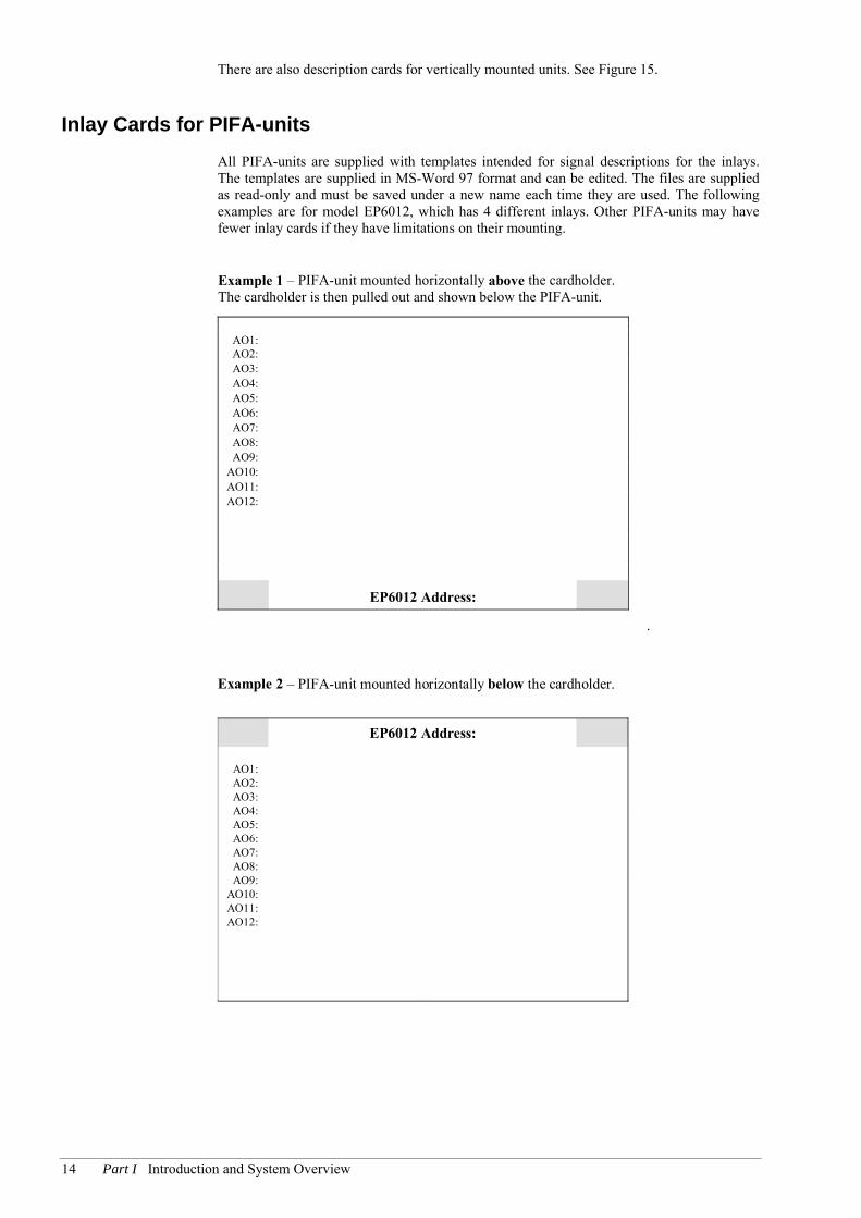
Inlay Cards for PIFA-units All PIFA-units are supplied with templates intended for signal descriptions for the inlays. The templates are supplied in MS-Word 97 format and can be edited. The files are supplied as read-only and must be saved under a new name each time they are used. The following examples are for model EP6012, which has 4 different inlays. Other PIFA-units may have fewer inlay cards if they have limitations on their mounting.
Example 1 – PIFA-unit mounted horizontally above the cardholder.The cardholder is then pulled out and shown below the PIFA-unit.
AO1:AO2:AO3:AO4:AO5:AO6:AO7:AO8:AO9:
AO10:AO11:AO12:
EP6012 Address:
.
Example 2 – PIFA-unit mounted horizontally below the cardholder.
EP6012 Address:
AO1:AO2:AO3:AO4:AO5:AO6:AO7:AO8:AO9:
AO10:AO11:AO12:

Chapter 2 Introduction to EXOflex 15
Example 3 – PIFA-unit mounted vertically to the right of thecardholder.
AO1:AO2:AO3:AO4:AO5:AO6:AO7:AO8:AO9:
AO10:AO11:AO12:
EP6012 Address:
Example 4 – PIFA-unit mounted vertically to the left of thecardholder.
AO1:AO2:AO3:AO4:AO5:AO6:AO7:AO8:AO9:
AO10:AO11:AO12:
EP6012 Address:

16 Part I Introduction and System Overview
Mounting EXOflex-units can be mounted horizontally or vertically. If mounted vertically, the use of fasteners is recommended.
Figure 10. Mounting the EXOflex house.
The unit is mounted in one of these two ways:
Horizontally
Vertically
Position 1
Position 1
Note that one power-PIFA must always be present in each house and is always mounted in position 1. In the event of damage as a result of the power-PIFA being incorrectly mounted, your guarantee will not be valid.
Horizontal Rail-mounting When mounted horizontally, the unit will hang on the integrated track in the aluminum chassis.
Figure 11. The EXOflex unit snaps quickly onto a TS 35 DIN-rail.
Snap quickly ontoa TS35 DIN-rail

Chapter 2 Introduction to EXOflex 17
Figure 12. The track at the rear the unit hangs on.
The track theunit hangson.
Use an end-stop on the DIN-rail so that the unit cannot move sideways.
Figure 13. Removing the unit.
Remove from the DIN-rail bybending the lower pegdownward while pulling thebase of the unit upwards.

18 Part I Introduction and System Overview
Wall Mounting The unit is mounted on a wall using fasteners. These slide into the runners at the rear of the aluminum chassis.
Figure 14. Wall mounting with fasteners.

Chapter 2 Introduction to EXOflex 19
Vertical Mounting When mounted vertically, the unit is rotated 90o clockwise, so that it stands on end, as in Figure 15. In this way, the power-PIFA will be located in the upper right position.
Figure 15. Vertical mounting of the EPU.
Power-PIFA
Inlay cardholders
In vertical mounting, the power PIFA is always located in the upper right position.

20 Part I Introduction and System Overview
External Display The EXOflex range includes a freestanding external display. See the figure below.
The external display is used for local display of alarms, changes to set-point values, etc. It is an independent PIFA that connects to a processor house via the EFX channel. See also Part III for software handling and Part IV for specifications.
Figure 16. The external display ED9200.
Chapter 2 Introduction to EXOflex 21
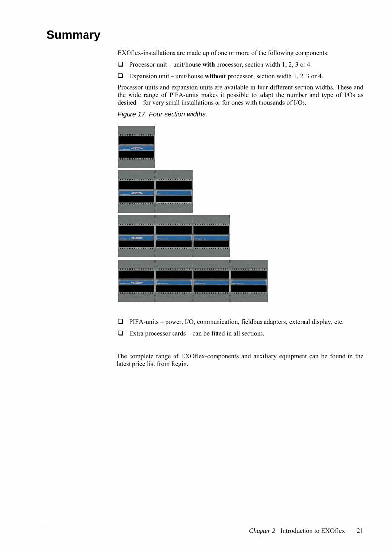
Summary EXOflex-installations are made up of one or more of the following components:
Processor unit – unit/house with processor, section width 1, 2, 3 or 4.
Expansion unit – unit/house without processor, section width 1, 2, 3 or 4.
Processor units and expansion units are available in four different section widths. These and the wide range of PIFA-units makes it possible to adapt the number and type of I/Os as desired – for very small installations or for ones with thousands of I/Os.
Figure 17. Four section widths.
PIFA-units – power, I/O, communication, fieldbus adapters, external display, etc.
Extra processor cards – can be fitted in all sections.
The complete range of EXOflex-components and auxiliary equipment can be found in the latest price list from Regin.
22 Part I Introduction and System Overview
Chapter 3 EPU Internal System Design
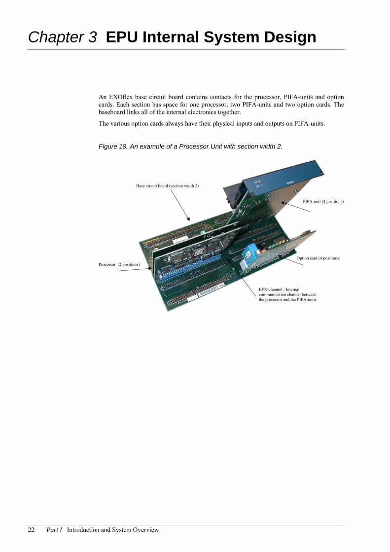
An EXOflex base circuit board contains contacts for the processor, PIFA-units and option cards. Each section has space for one processor, two PIFA-units and two option cards. The baseboard links all of the internal electronics together.
The various option cards always have their physical inputs and outputs on PIFA-units.
Figure 18. An example of a Processor Unit with section width 2.
PIFA-unit (4 positions)
Option card (4 positions)
EFX-channel - Internalcommunication channel betweenthe processor and the PIFA-units
Base circuit board (section width 2)
Processor (2 positions)

Chapter 3 EPU Internal System Design 23
Isolation Barrier The parts of the PIFA-units close to the process are separated from the internal electronics by an isolation barrier, which is bridged by the use of an optocoupler. This provides for optimum handling of difficult electrical environments.
This also means that the parts of the PIFA-units close to the process must get their power from an external source, which could well be the same as the source supplying the whole EXOflex-unit.
Figure 19. The isolation barrier.
Internal electronics
Isolation barrier
Addressing PIFA-units The processor in the position furthest to the left in Figure 20 (the main processor) normally communicates with all of the houses’ PIFA-units. In certain cases however, you will want to use one or more extra processors, and in this case, these slave processors will take over the PIFA-units in their own sections and in the following ones. In the example below, the main processor addresses the PIFA-units in positions 2,3 and 4. The slave processor in section 3 addresses the PIFA-units in positions 5,6,7 and 8. Communication from processor to PIFA-unit is via the EFX-channel, which runs along the baseboard. In the example, the EFX-channel is divided into two separate channels, one for each processor.
An external display is always addressed from the main processor and via its EFX-channel.
24 Part I Introduction and System Overview
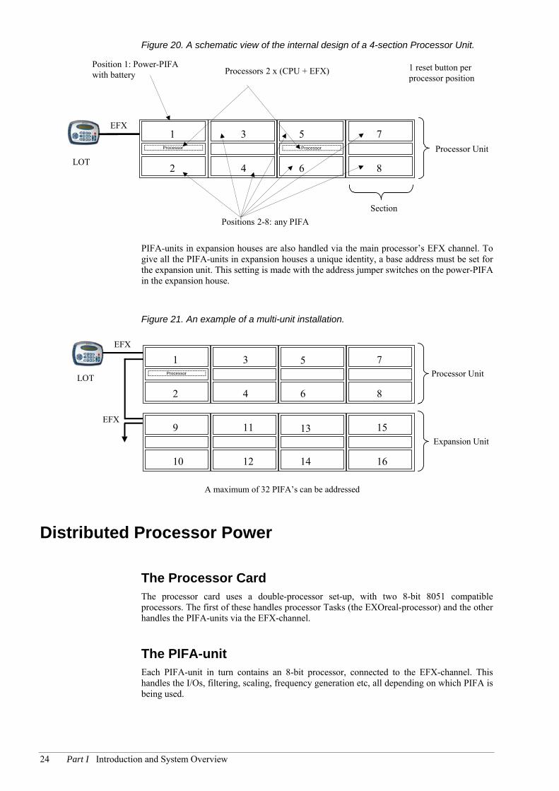
Figure 20. A schematic view of the internal design of a 4-section Processor Unit.
Processor Unit
Processors 2 x (CPU + EFX)Position 1: Power-PIFAwith battery
Section
LOT
EFX
2
Positions 2-8: any PIFA
3
4 8
75
6
1
1 reset button perprocessor position
Processor Processor
PIFA-units in expansion houses are also handled via the main processor’s EFX channel. To give all the PIFA-units in expansion houses a unique identity, a base address must be set for the expansion unit. This setting is made with the address jumper switches on the power-PIFA in the expansion house.
Figure 21. An example of a multi-unit installation.
Processor UnitLOT
EFX
2
A maximum of 32 PIFA’s can be addressed
3
4 8
75
6
1
Expansion Unit
10
11
12 16
1513
14
9EFX
Processor
Distributed Processor Power
The Processor Card The processor card uses a double-processor set-up, with two 8-bit 8051 compatible processors. The first of these handles processor Tasks (the EXOreal-processor) and the other handles the PIFA-units via the EFX-channel.
The PIFA-unit Each PIFA-unit in turn contains an 8-bit processor, connected to the EFX-channel. This handles the I/Os, filtering, scaling, frequency generation etc, all depending on which PIFA is being used.
Chapter 3 EPU Internal System Design 25
The Built-In Battery All units have an in-built battery for data memory. The battery on the power-PIFA must be changed regularly. The recommended replacement period is five years.
The old battery can be replaced with no loss of memory, but the procedure should not take longer than 30 minutes. See Chapter 22 Changing the Battery.
Serial Ports An EXOflex processor can have a maximum of 3 serial ports, just as all other EXO controllers. The ports are called Port 1, Port 2 and Port 3, or P1, P2 and P3 for short. Serial ports are not handled by independent PIFA’s via EFX (as for e.g. digital inputs), but by EXOreal directly.
There are also other types of communication ports that are handled by independent PIFA-units, e.g. the EXOlon PIFA and the TCP/IP PIFA-units that are used as gateway in Lon and TCP/IP networks.
To use Ports 1-3, special connection-PIFA’s must be used.
This means that the 3 ports have the same properties, possibilities and limitations as other models. All of the software-based configuration, interfaces etc, is identical to that in other models.
Ports 1-3 can be used for RS232 or RS485 (EXOline) and are galvanically separated from each other and from the internal electronics. Selection of RS232 or RS485 interface is hardware-based. In some applications with long communication distances, there is a further option available for the RS485 interface, i.e. to transmit at higher power, so-called hlEXOline.
When using RS232 on Port 1, this is always limited to the signals RxD, TxD and RTS, whilst on Port 2 you will have RxD, TxD, RTS, CTS, and on Port 3, a complete set of signals for RS232, i.e. RxD, TxD, RTS, CTS, DTR, DSR, RI and DCD. EXOreal’s support for dial-up modems for EXOline-communication is thus limited to Port 3.
To use the serial ports, you must use the PIFA’s port-connections. These are not configured in EXOflex Tool, but are simply installed physically in the intended positions.
Examples of PIFA units with port connections are the power-PIFA EP1011 and the double port PIFA EP8102.
The power PIFA must be used on position 1 (in the processor house) The double port PIFA can be used in other positions. Port connections cannot be used in expansion houses at all.
This means that Port 1 (from the main processor) can be obtained via the power-PIFA and, as mentioned earlier, in the form of an RS232 interface and an RS485 interface.
The double port PIFA contains, as the name implies, two port connections (P2 and P3), and it can be used in all other positions in the processor house. The port connections go to different serial ports, depending on the position in the processor house. Furthermore, there is space for an option card, which can be connected to P2 or P3 on the PIFA.
If the double port PIFA is used in position 2 in the processor house, port 2 and 3 (from the main processor) are obtained via the PIFA. If the double port PIFA is used in another position, you will only get P2 (from the main processor).
See below:
26 Part I Introduction and System Overview
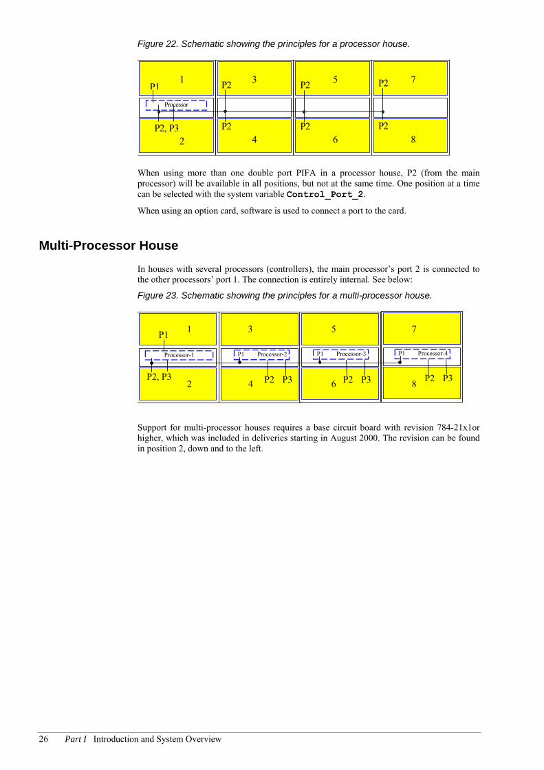
Figure 22. Schematic showing the principles for a processor house.
Processor
P1
P2
P2
P2
P2
P2
P2
4 6 8
731 5
P2, P32
When using more than one double port PIFA in a processor house, P2 (from the main processor) will be available in all positions, but not at the same time. One position at a time can be selected with the system variable Control_Port_2.
When using an option card, software is used to connect a port to the card.
Multi-Processor House In houses with several processors (controllers), the main processor’s port 2 is connected to the other processors’ port 1. The connection is entirely internal. See below:
Figure 23. Schematic showing the principles for a multi-processor house.
P1Processor-1
5
6
7
8P2, P3
P1 Processor-2 P1 Processor-3
P3P2
P1 Processor-4
P3P22 86
531
4
7
P3P2
P1
Support for multi-processor houses requires a base circuit board with revision 784-21x1or higher, which was included in deliveries starting in August 2000. The revision can be found in position 2, down and to the left.

Chapter 4 Naming System for EXOflex Components 27
Chapter 4 Naming System for EXOflex Components
Houses (process houses/expansion houses)
EHxy[P]
H = House
x = Number of sections
y = Number of processors
Examples:
EH10 – one section, no processor
EH41 – four sections, one processor
PIFA-units
EPxynn[P] nn = number of connections
P = PIFA y = type variant
x = PIFA type 1 = Power 2 = DI 3 = DO 4 = Mixed DI/DO 5 = AI 6 = AO 7 = Mixed I/O 8 = Special 9 = External Display
E.g. EP1011 = Power PIFA EP2032 = 32 DI EP6012 = 12 AI EP8102 = Dual Basic Serial EP9040 = LOT

28 Part I Introduction and System Overview

Chapter 4 Naming System for EXOflex Components 29
PPaarrtt IIII IInnssttaallllaattiioonn aanndd CCoommmmiissssiioonniinngg

30 Part II Installation and Commissioning
Table of contents Part II Installation and Commissioning
Chapter 5 Cabinet Installations 31 Cabinet Layout 31
Chapter 6 Power Supply 33 24V DC Units 33
Power PIFA-units 33 Other PIFA-units 34 Check the Power Requirements 35 Maximum Limits 35
Chapter 7 Communication Buses & Interfaces 36
EXOline 36 hlEXOline 37 SIOX Bus 37 M-Bus 37 The RS232 Interface 37 The Ethernet Interface 37 The SO Interface 38
Chapter 8 Connecting Active Transmitters to Inputs 39
The Two-Wire Transmitter 39 The Three-Wire Transmitter (PNP-type) 40 The Three-Wire Current Sink Transmitter (NPN-type) 40 Other Considerations 40
Chapter 9 Commissioning 41 Setting Addresses 41

Chapter 5 Cabinet Installations 31
Chapter 5 Cabinet Installations
A correct cabinet installation entails, amongst other things, not mixing cables for sensitive analog measurements with disruptive power cables. It is therefore very important that the cabinet area is used properly. As you can choose which position in the EXOflex-unit to mount a particular PIFA-unit, you can then e.g. put analog PIFA-units on the one side and digital PIFA-units on the other. This will result in a natural separation of sensitive and disruptive cables.
The following section provides further tips for creating an installation that complies with EMC requirements.
Cabinet Layout Figure 24. A typical cabinet layout.
Over-voltage
protector
Relays
Separate analog signals from digital
Ground Rail
TelephoneLine
Line
LineFilter
Power Supply
DigitalSignals
AnalogSignals
A Few Rules Use a heavy ground rail close to where external cables enter the cabinet. The rail should
be connected to local ground with a heavy wire.
If using a steel cabinet, it and its door should be connected to the ground rail for safety.

32 Part II Installation and Commissioning
The output contacts of power relays should be connected to wires that are separated from other wiring as much as possible.
Contactors switching heavy loads can be prevented from causing interference in other parts of an installation by using a transient protection device on the contactor output. This RC network is sometimes an integrated part of the contactor.
If a power-supply filter is used, it should be mounted close to the rail and grounded at the rail.
If lightning protection is used on the communications line, it should be mounted directly on the rail.
Use separate ground wires for each ground connector on each controller and each power supply. Always connect grounds to the rail.
Conductors connecting modems to controllers are more sensitive than other connections. These should be kept together and not be mixed with other cables unless absolutely necessary.
If shielded wires are used outside the cabinet, the shield should be properly connected to the ground rail.
If shielded cables are used inside the cabinet, the shield should be connected to the rail. Internal shielding is an excellent way of improving interference protection from external cables that are being exposed to heavy disturbances.
Do not install frequency converters in the same cabinet as regulation equipment. It is our experience that frequency converters, even CE-marked ones, generate extremely heavy interference, often far beyond the allowed limits.
Controllers are often mounted in cabinets containing relays, actuators, transformers and other equipment. This should normally not be of any concern. However, actuators handling heavy currents (>10A) must always be mounted in separate cabinets.

Chapter 6 Power Supply 33
Chapter 6 Power Supply
The EXOflex system with its separate PIFA-units can be viewed as galvanically isolated “processing islands”, where each island normally requires an external power supply. This design provides a number of possibilities and advantages:
Each PIFA-unit (processing island) can be powered by separate, isolated power units. This means the galvanic insulation from other processes can be retained, if this is desired.
Very accurate analog measurements can be made.
Battery backup of selected processes.
Separately fused processes, and thus better error handling.
When the advantages above are not required, some, or all, of the PIFA-units can be powered by the same source, which may also be used for active two-wire sensors and output relays, etc. Note that the maximum load of the supply must not be exceeded.
Note also that long cables will introduce a voltage drop that may impair correct operation of the units. A 1.5mm2 conductor typically has a resistance of 11 Ω/1000 m. If carrying 1 A, the drop will be 2.2 V per 100 meters of cable (two conductors). It is therefore recommended that a separate power supply be used at each location where units are mounted.
To avoid high, ground relative voltages, it is recommended that the power supply is grounded. The best point is at the negative pole of the power supply.
24V DC Units Although a stabilized power supply is highly recommended, you may use a rectified AC supply with a filter capacitor, with a value depending on the load and permissible tolerance on the input voltage.
Note that external power supplies generating 24V DC for EXO controllers must be CE marked as SELV, safety extra low voltage, or PELV, protected extra low voltage, power supplies.
Observe that the peak and lowest momentary value of the filtered supply voltage must be within the supply tolerance specified for the model. If you are using a rectified AC supply, momentary values cannot normally be measured with a standard voltmeter, but instead require an oscilloscope.
Power PIFA-units
Connection to power supply
All power PIFA-units have a galvanically insulated DC/DC converter that generates the internal supply for the logic circuits and, in some cases, galvanically insulated voltages for external equipment (see Part IV Specifications). The 0 V circuit is the terminal marked 0 V and the positive +24 V.

34 Part II Installation and Commissioning
The 0 V circuit should be grounded at the power supply, to define the potential with reference to ground and to compensate for disturbances and transients from I/O signals.
The Protective Ground Circuit, EMI ground
This terminal is located close to the power terminals and labeled . It is connected internally to the PIFA frame and to internal protective circuits. It should be connected with a separate, heavy wire to the ground rail.
Other PIFA-units Connection to power supply
All processing PIFA units must be connected to an external power supply, which may be the same supply as for the Power PIFA. The 0 V-circuit is the terminal marked 0 V, and the positive+24 V.
The 0 V-connection is normally grounded at the supply source, so as to define the potential to earth reference and to compensate for disturbances and transients from I/O signals.
The Protective Ground Circuit, EMI ground
This terminal is located close to the current terminals and is marked . It is connected internally to the PIFA’s frame and to internal protective circuits. It should be tied with a separate, heavy wire to the ground rail.
The RS232 connections (Port 1, 2 or 3)
These connections are galvanically isolated from the internal circuits. The signal zero is marked Gnd. Use screened cable and earth it at one point.
The EXOline-connection ( Port 1, 2 or 3)
Galvanically insulated from all other circuits. The 0V reference is labeled N and should be tied to the screen of the communication cable, which in turn should be grounded at least one point.
Digital input and output connections.
Inputs should be referenced to +C (+24 V) and outputs to –C (0 V)
Analog input connections
Voltage and resistance measuring (PT100 etc.) is relative to Agnd.
Screened cables must be used and the screens connected to the SCR-connector next to the input connection. Alternatively, the screen can be connected to the ground rail according to Figure 24 on page 31. In most cases, this alternative connection will give a measurement result that is accurate enough. However, in harsh electrical environments we recommend that the screen is connected to SCR. Power supply for transmitters etc. is from the fused +C output on the AI PIFA-unit.
Analog output connections
Analog output voltages are referenced relative to Agnd.
Certain PIFA-units have a connection for screened cables for analog outputs. The connection is SCR.

Chapter 6 Power Supply 35
Check the Power Requirements The PIFA-unit’s internal circuits and option cards get their power supply from the power-PIFA. This internal voltage is mostly 5 V, but other voltages can also apply, e.g. ±12 V.
So as to not exceed the maximum power output from the power-PIFA, you must ensure that the total internal power requirements of all the individual PIFA-units and options do not exceed the power-PIFA’s maximum current supply on the internal voltages.
More information can be found under the information for each PIFA in Part IV
Maximum Limits Care must be taken during installation and commissioning that inputs, outputs, ports and supply terminals are not subject to excessive voltages due to incorrect external connections.
A safe routine during installation is to connect the plug-in contacts to the PIFA-units only when all external cables have been connected and tested.

36 Part II Installation and Commissioning
Chapter 7 Communication Buses & Interfaces
EXOline EXOline is the standard means for communication via fixed cables.
The EPUs are connected in parallel on the line, as shown in Figure 25.
Figure 25. EXOline - Parallel Connected EPUs.
Screened and twisted cables should be used. The area should be 0,25 mm2 or more, as dictated by mechanical considerations, and the capacitance should be less than 100 pF/m. The line should normally be terminated at both ends (last controller at each end) with a resistor value of 100 Ω/0.5 W
The line may be branched into several lines in a tree structure. If one of the branches should exceed 200m, it is recommended that the line be terminated with an nx100 Ω resistor at the last controller in each branch (n = No of branches). Up to 50 controllers may be connected on the same line without amplification. The screen should normally be grounded at least at one point, normally the N terminal on the master unit.
The E-signal EXOline carries messages in both directions on the same pair of conductors. A special signal is used to control the communication direction when converting to RS232 and EXOloop. This signal is called the E-signal.

Chapter 7 Communication Buses & Interfaces 37
hlEXOline hlEXOline is an enhanced EXOline port capable of supplying more power to the line and handling line receivers with higher sensitivity than the standard EXOline port. Extended communication distances may thus be achieved by using hlEXOline. The cable area should be 0.5 mm2 or more, as dictated by mechanical considerations and with terminations as for EXOline, but the resistor should be able to dissipate 2 Watts (100Ω/2W), due to higher line power.
hlEXOline is obtained by moving a jumper switch on the power-PIFA (Port 1) or on the communication-PIFA (Port 2–3). See the descriptions for each PIFA-unit in Part IV Specifications.
Note that hlEXOline and EXOline must not be mixed on the same communication loop.
SIOX Bus The SIOX bus is a two wire asynchronous bus with a level of 24 V DC. The wire should normally be a twisted pair and the recommended cable area is 1.5 mm2. The bus should not normally be terminated.
See also documentation from Telefrang AB for more information regarding the properties of the SIOX bus.
M-Bus The M-Bus, or Meter Bus, is a two wire asynchronous bus and 42 V DC power supply for connected meters. The wire should normally be a twisted pair and the recommended cable area is 1.5 mm2. The cable should not be longer than 3 km for 2400 bps communication speed. The bus should not normally be terminated.
The RS232 Interface RS232 is used for communication between two devices, port to port, on normally fixed cables.
A screened cable must be used. The area should be 0.25 mm2 or more, as dictated by mechanical considerations, and the length should not exceed 15 meters, unless otherwise specified in the data sheet. The RS232 port on EXOflex-units is normally insulated from the internal circuits, but the RS232 cable should nonetheless be separated from heavy disturbances.
The Ethernet Interface Ethernet is an interface used for constructing computer networks. Ethernet is not specific for any particular media or communication speed and it is used often for creating local area networks (LANs), radio networks and fiber optic networks using very high speeds.
One of the most common standards for Ethernet in a LAN is IEEE 802.3, which is Ethernet with a transfer speed of 10 Mbits. The usual way to connect to a 10Mbit Ethernet network is via 10Base-T, which is the technical term for twisted-pair Ethernet. Other connection methods used for 10 Mbit Ethernet are 10Base-2/BNC (thin-wire Ethernet) and AUI (thick-wire Ethernet).

38 Part II Installation and Commissioning
When connecting equipment to a twisted pair Ethernet network, a so-called TP cable is used. The TP cable is an 8-pole twisted pair cable with an impedance of 100 Ohms impedance and RJ45 connectors at both ends. The TP cable is either screened (STP) or unscreened (UTP). EXOflex-units that are connected to Ethernet have a screened RJ45 connector and should therefore be connected by screened TP cable (STP). To avoid disturbances to network traffic, the cable should not be spliced or pass a plinth.
The SO Interface The SO interface is a commonly used interface for energy meters. Some digital inputs can handle SO signals directly, by selecting SO logic levels via jumpers on the PIFA-unit.
The connection diagram in the figure below shows a meter with SO interface with open collector output and a common + pole.
Figure 26. The SO interface.
+
_
Meter EXOMATIC module
+ C
DIN
(24V+)
SO

Chapter 8 Connecting Active Transmitters to Inputs 39
Chapter 8 Connecting Active Transmitters to Inputs
Active transmitters supplying 0–20 mA or 4–20 mA are frequently used for flow, pressure, differential pressure, etc. There are three basic categories available.
The Two-Wire Transmitter This type is typically powered by 12–24 V DC and varies its current consumption proportionally to the input in the range 4-20 mA. This type is connected with the positive terminal to +C (+24 V), or better still, to 12 V DC if available and is sufficient for the transmitter. The negative pole is connected to the analog input with the current shunt activated. If the transmitter is short circuited, excessive current will be fed into the controller, which will be damaged. To protect the controller, use a fast fuse in the circuit or a separate, current limited supply. Note that Agnd must not be connected. Instead the current through the shunt must be re-routed via the PIFA-unit’s 0 V-connection. The fuse can be omitted if the transmitter is supplied by 12 V instead of +C (24 V).
Figure 27. Connection of Two-Wire Transmitter.
Fuse+C
AGnd
+C
40 Part II Installation and Commissioning
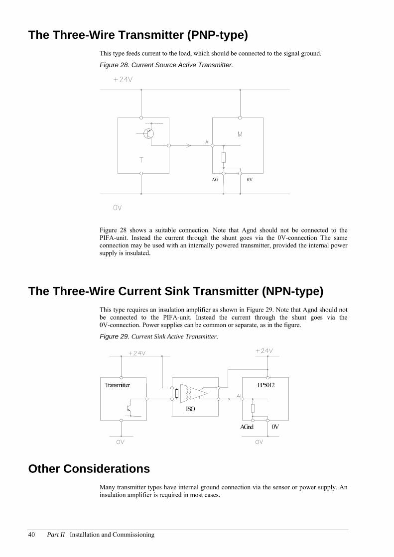
The Three-Wire Transmitter (PNP-type) This type feeds current to the load, which should be connected to the signal ground.
Figure 28. Current Source Active Transmitter.
0VAG
Figure 28 shows a suitable connection. Note that Agnd should not be connected to the PIFA-unit. Instead the current through the shunt goes via the 0V-connection The same connection may be used with an internally powered transmitter, provided the internal power supply is insulated.
The Three-Wire Current Sink Transmitter (NPN-type) This type requires an insulation amplifier as shown in Figure 29. Note that Agnd should not be connected to the PIFA-unit. Instead the current through the shunt goes via the 0V-connection. Power supplies can be common or separate, as in the figure.
Figure 29. Current Sink Active Transmitter.
AGnd 0V
EP5012Transmitter
ISO
Other Considerations Many transmitter types have internal ground connection via the sensor or power supply. An insulation amplifier is required in most cases.

Chapter 9 Commissioning 41
Chapter 9 Commissioning
Setting Addresses Each PIFA must have a unique address in the interval 0 to 31.
PIFA-units mounted in an EXOflex-house will receive an address depending on their position in the house. The position at the uppermost left has the address 1, the position under that has address 2, the position to the right of position 1 has the address 3 and so on. See the figure below.
1 3 5 7 2 4 6 8
In a processor house, with one or more processors, the PIFA-units will have these addresses as standard upon delivery, i.e. the power-PIFA’s address jumpers are set to the base address 0.
In expansion houses, base addresses can be set using a group of jumper switches. The base addresses are selected as follows:
Base address Jumpers 3 2 1
28 24 20 16 12 8 4 0 (Standard setting for processor house)
3, 2 and 1 in the table refer to Figure 31.
The PIFA-unit’s address is then obtained by adding the base address to the PIFA-position’s address. The external display PIFA always has the address 0.

42 Part II Installation and Commissioning
Example Figure 30. Addressing in a system with one processor unit and one expansion unit.
Processor UnitBase address 0
Add the base address to the position address to get the PIFA-unit’s address
Expansion UnitBase address 8
EFX
EFX
2
3
4
5
6
1
10
9
(0+1)
(0+2)
(0+3)
(0+4)
(0+5)
(0+6)
(8+1)
(8+2)
11
12
(8+3)
(8+4)
13
14 (8+6)
(8+5)
LOT
0
Processor
To avoid ESD damage to the electronics, you must use a wristband connected to earth for this procedure.
Figure 31. The jumper switches for setting base addresses on the EPU’s power PIFA.
3 2 1
The jumpers for setting base addresses. Here they are set for the baseaddress 28, i.e. no jumpers have been set.

Chapter 9 Commissioning 43
PPaarrtt IIIIII EEXXOOfflleexx SSooffttwwaarree

44 Part III EXOflex Software
Table of contents Part III EXOflex Software
Chapter 10 Overview 47 Configuration 47
Chapter 11 EFX PIFA Units 49 Resources 49 Configuration 49
Commands 50 Changing the Configuration 50
Application Interface 50 Read, Write and Parameter Variables 51 Control Variables 52
Run Modes 52 Normal Run 52 No Power 53 Power-up 53 Off-line Mode 54 Communication Disturbance 54 Spontaneous Warm-start 54
Other Considerations 54 PIFAos 54 Serial Number 55
Chapter 12 The Processor and the Power-PIFA 56
EXOreal 56 The EFX Channel 56 Hardware Clock 57 Built-in Battery 57 External Battery (Option 9035) 57 Digital Inputs and Outputs (on the Main Power PIFA) 58
Chapter 13 Communication 59 Electrical Formats 59 Connections 59
The Main Processor 59 Other Processors 60
System Variables 61

Chapter 9 Commissioning 45
Chapter 14 Digital Inputs 62 General 62 Function 62
Run-time Logging 63 Pulse Counting 63 Pulse Rate Measuring 64
Function Diagram 65 Configuration 65 Variables 66
Chapter 15 Digital Outputs 67 General 67 Function 67
Pulse Proportioning 68 Frequency Generation 68 Power-up 69 Off-line Mode 69 Overheating Protection 69
Function Diagram 70 Configuration 70 Variables 70
Chapter 16 Analog Inputs 72 General 72 Function 72
Compensation for Wire Resistance 72 Measurement Range 73 Priorities 73
Function Diagram 74 Configuration 74 Variables 75
Chapter 17 Analog Outputs 76 General 76 Function 76
Power-up 76 Off-line Mode 77
Function Diagram 77 Configuration 77 Variables 78
Chapter 18 The External Display 79 The Display 79 Keypad 79 LEDs 81

46 Part III EXOflex Software
Beeper 81 Character Sets 82
Chapter 19 TCP/IP 83 General 83 Network Construction 84 Security 84 Performance 85
Unreachable Controllers 85 Configuration 85
Load the Configuration 90 Loading the Operating System 93 Advanced Applications 93
Multidrop 93 Multimaster 94 Firewalls 94
Hardware Interface 95
Chapter 20 Applications 96 Controller Objects 96 Display 96 Limitations 98

Chapter 10 Overview 47
Chapter 10 Overview
EXOflex’ mechanical design, which uses different types of houses, has little meaning when programming. Instead we use the logical concept of controllers.
In earlier EXO systems, the term module was used to describe both hardware and software. In the EXOflex system, however, we define a module (controller) as:
A processor (using EXOreal) and its PIFA-units.
A processor house can thus contain one or more controllers and it is also possible to connect one or more expansion houses to the processor house. These together then make up a controller. This definition of a controller is used exclusively in EXOdesigner, EXO4, etc.
Each EXOflex-controller can handle a maximum of 32 PIFA-units. There are two basic types of PIFA-units: EFX-units and non-EFX-units.
EFX PIFA Units EFX PIFA units communicate with EXOreal in the processor house via the so-called EFX channel. EFX is RS485 based communication, which is only intended for use between PIFA units and EXOreal. The EFX channel runs between all the PIFA units in a house, but can also be run via a cable from one house to another.
This type of PIFA can be placed in any position in processor or expansion houses, with identical functionality.
EFX PIFA units have their own CPU, which uses the operating system PIFAos. The operating system in the PIFAs and EXOreal handle all communication between each other completely automatically and invisibly. The result of this is that the PIFA units’ functionality is exposed via ordinary EXOL variables in VPacs.
Non EFX PIFA Units
Non EFX PIFA units do not communicate with EXOreal in the processor house via the EFX-channel, but by special connections inside the processor house. This is used by power and communication PIFAs, which cannot be used in expansion houses. Furthermore, there are special rules for which positions they may occupy in the processor house.
EXOreal handles non EFX PIFA units directly, as if they were built into the processor, in the same way as in earlier EXO systems. Non EFX PIFA units can have their own CPU, but do not have to.
Configuration EXOflex-controllers are created and programmed in the usual way, using Project Builder, Controller Functions, EXOL files, etc.
To configure the functions in an EXOflex controller, you use the controller function EXOflex I/O, which is added with Controller Functions in the usual way.
Configuration does not take place on-line, but instead in EXOL files on the hard drive (exactly as for all other controller functions). The configuration is loaded to the controller together with the application programs.
The configuration of EXOflex and the PIFA units is the only difference as concerns application programming of the controllers, everything else is the same as usual. All the existing programs in EXOdesigner (and other, third-party programs) can be used as they are.

48 Part III EXOflex Software
During configuration you must specify which PIFAs are being used. This is done with EXOflex I/O Tool:
Figure 32. EXOflex Tool.
Add a PIFA by clicking New and selecting the model in the dialog Add PIFA:
Figure 33. Add a PIFA-unit.
A new PIFA unit is assigned the first available address. This is then changed to the actual address in the attribute Address.
Both EFX and non EFX PIFA units must be defined in EXOflex I/O Tool. The individual functions for each PIFA are configured separately in a special tool. Most PIFA units are configured with PIFA I/O Tool.
You can also provide a description for each PIFA. All other configuration is described in Chapter 11 EFX PIFA Units.

Chapter 11 EFX PIFA Units 49
Chapter 11 EFX PIFA Units
EFX PIFA units are in many cases advanced, with many possible settings. Configuration is done (in most cases) with PIFA I/O Tool.
Resources A PIFA often contains a number of separate units, e.g. analog inputs or digital outputs. Each such unit is called a resource. Both the hardware and software are organized by resources.
In the case of software, a resource is roughly equivalent to an object. There are a number of standardized software resource types, which are to be found in many different PIFA units in various combinations.
Configuration Most types of PIFA units are configured with PIFA I/O Tool. There are, however, certain advanced types of PIFA units that have their own tools. You start a PIFA unit’s configuration tool from EXOflex I/O Tool.
Figure 34. An example of a PIFA I/O Tool window:
In PIFA I/O, each resource is configured as a separate object. The configuration attributes vary, depending on the resource type. See the description for each resource type.
There are, however, certain attributes that are always available for all resource types: Description and Name.
Description is intended for describing the resource in the application.
Name is intended for giving the resource another programmatic name than the default. See also Application Interface below.

50 Part III EXOflex Software
During configuration, a number of VPacs with variables equivalent to the PIFA-units’ interface variables are created. A BPac is also created, which has pointers to all these data structures, as well as a few other settings.
Commands
Debug Teh command Debug starts EXOtest in order to inspect the attribute variables of the selected resources. An .ete file is created for each resource. You start a debug session either by pressing the button or with the key combination Alt+U.
Synchronize Parameters The command Syncrhonize Parameters is used to read the configuration parameters from the controller. In this way you can synchronize the project’s configuration in the software with the actual configuration in the controller. To execute a synchronization you press the button or use the key combination Alt+R.
Changing the Configuration As mentioned above, configuration is done in EXOL files on the hard drive, in the files PIFAConf.Dpe, PIFA.Dpe and PIFACtrl.Dpe.
The EXOL-files are loaded to the controller with the command Load Controller, just as other EXOL files. However, when changes have been made, you cannot simply reload the files, but must instead reload the entire controller, i.e. cold or cool start it.
Note that the application can change the value of a parameter variable during run time without changing the configuration. When the PIFA is reloaded however, all the variables will receive the values stored in the configuration.
Application Interface The EXOflex controller’s application is programmed as usual in EXOL files, which can interact with other controllers and operator programs (e.g. EXO4) in the usual way.
This is possible due to the fact that the interface between the PIFA units and the application programs goes via ordinary EXOL variables in VPacs. The VPacs are created on the hard drive during configuration and loaded to the controller with the command Load Controller. The operating system in the EXOflex controller and the PIFA units automatically and invisibly takes care of the transfer between the PIFA units and the variables in the VPacs.
The VPacs with variables are called PIFA.Dpe etc. The function EXOflex I/O automatically declares these in the process Tasks (Normal, Slow, Fast and VeryFast).
The variables are divided into four different data classes, according to how data is transferred, according to the below:
Data class Description
Read variables Transferred automatically from the PIFA units to the controller upon changes. Will be read by the application programs. See however, Counter Variables below.

Chapter 11 EFX PIFA Units 51
Write variables Can be written or read by the application programs. Transferred automatically from the controller to the PIFA units upon changes.
Parameter variables
Can be written or read by the application programs. Transferred automatically from the controller to the PIFA units upon changes, i.e. as for write variables, but at a lower priority.
Control variables
Special variables, valid for the whole PIFA, irrespective of the PIFA’smodel. The variables have various meanings. There are variables for e.g. indicating status, serial number, PIFAos revision etc. These variables are stored in PIFACtrl.Dpe (which is not declared automatically in the process Task).
Read, Write and Parameter Variables
Each PIFA has its own set of read, write and parameter variables. Normally all PIFA units of a particular model have a fixed set of variables. This means that for each PIFA model you install, you will get the same set of variables. There can however, be PIFA units with a dynamic set of variables, where even the variable set itself depends on the configuration.
The variables are usually organized and named according to their resources, so that all the variables belonging to a particular resource start in the same way, i.e. with the resource name. The name of the attribute follows directly after the resource name.
Each resource has a default name. This name is normally constructed from information about the resource type, the PIFA-address and the resource number. Examples of default resource names are AI1_2 and DI3_7, for analog input 2 in PIFA 1 and digital input 7 in PIFA 3 respectively. You can however, during configuration give each resource any name, e.g. OutTemp, FanGuard, Pump, etc.
Example:
A normal digital input has a variable that registers the input’s value. This variable is special, as its name is equivalent to the resource’s name, e.g. DI3_7 or Fanguard. A digital input also has variables for selecting on/off delays. These are called OnDelay and OffDelay respectively. The variable names for these will then be DI3_7OnDelay, DI3_7OffDelay, FanGuardOnDelay and FanGuardOffDelay.
Indexing In most cases, an attribute for all the resources in a PIFA is also available for indexing, which can be exploited in loops in application programs. In this case, the default name in the variable name is always used. The resource numbers are used as an index, instead of the actual variable name.
Example:
On/off delays for the digital inputs in PIFA 3 are available in the indexed variables DI3OnDelay(x) and DI3OffDelay(x) respectively, where x is the resource number.
Counter Variables Read variables can normally only be read by application programs. If you write something in such a variable, this value will be overwritten as soon as a new value is generated by the PIFA. An exception to this is counter variables, which e.g. count pulses or track run time for a digital input. This type of variable can be both read and written. If you enter something into a variable of this type, it will proceed to count from the value you entered.

52 Part III EXOflex Software
Transient Flags All read variables have transient flags that are set when the value is changed. Especially for digital inputs, there are flags that are set also for very short pulses. See Chapter 14 Digital Inputs on page 62.
You cannot use the transient flags for write and parameter variables in application programs in EXOflex, since they are used internally by EXOreal.
Control Variables The control variables apply to the whole PIFA and are therefore not organized by resource. The names of these variables can not be configured. They always start with PIFAx, where x is the PIFA address, followed directly by the name of the attribute.
Example:
The serial number for the PIFA in position 3 can be read in the variable PIFA3_SerialNumber.
The control variables are placed in their own VPac, named PIFACtrl.Dpe (which is not declared automatically in the process Task).
Run Modes A PIFA can run in a number of different modes, as described below.
Normal Run When a PIFA is in normal run mode, it is said to be in its active mode. Values are then automatically transferred between the PIFA and the EXOL-variables in the controller. The transfer is event-driven, i.e. values are only transferred when they change. Although the process is event-driven it is not immediate. There are certain delays in the system.
The delays are dependent on the variable’s data class, the number of PIFA units and the PIFA’s priority. If all the PIFA units have the same priority, the maximum delays can be calculated in the following way:
Read variables: 20 + (NumberOfPIFA-units * 1.4) milliseconds.
Write variables: 20 * NumberOfPIFA-units milliseconds.
Parameter variables: 400 * NumberOfPIFA-units milliseconds.
In EXOflex I/O Tool, you can configure the priority for each PIFA. This can be exploited if you have a limited number of PIFAs that need much faster transfer than the other ones. The priority is specified numerically, the value 1 is the highest priority. It can be fairly complicated to calculate the maximum delay when priorities are stated in this way. However, the maximum delay between two PIFA units is inversely proportional to the relationship between their respective priorities, i.e. a PIFA with priority 1 is 3 times as fast as a PIFA with priority 3, which in turn is twice as fast as a PIFA with priority 6, and so on.
You can also change the priority of parameter variables in relationship to write variables. Normally write variables are 20 times faster, but this can be configured in the parameter Priority for scanning for changes in the parameter variables in PIFA I/O Tool.
Chapter 11 EFX PIFA Units 53
No Power When a PIFA has no power, then naturally nothing happens. All outputs are "low", even digital outputs with relays. This is always equivalent to the value 0 during normal operation in the corresponding write variable for the application programs.
Power-up
A PIFA usually has no battery and will therefore not "remember" anything of its configuration, settings or values for outputs, etc. All outputs will therefore be "low".
The EXOflex controller however, contains all the variables and their configurations, values, etc. When both the PIFA and the controller are powered up and have made contact, the controller will automatically update the PIFA with this information. Once this is done, the PIFA’s continued behavior will depend on its configuration for Type Of Activation in EXOflex I/O. Automatic or manual activation can be selected.
If automatic activation is selected, the PIFA will automatically go to active mode (i.e. normal operation) as soon as the PIFA and the controller have been updated.
If manual activation is selected, the PIFA will instead go to passive mode as soon as the PIFA and the controller have been updated. In passive mode, values are automatically transferred between the PIFA units and the EXOL variables in the controller, just as in active mode, but all outputs will remain "low". Inputs and other resources function exactly as in active mode.
The PIFA will remain in passive mode until it is activated manually, usually by the application program. Manual activation is intended for use in sensitive installations, where various equipments need to be started in very special ways after power-up.
Apart from this advanced function, output resources usually also have other, simple functions for start-up, e.g. PowerUpDelay. See the description for each resource type.
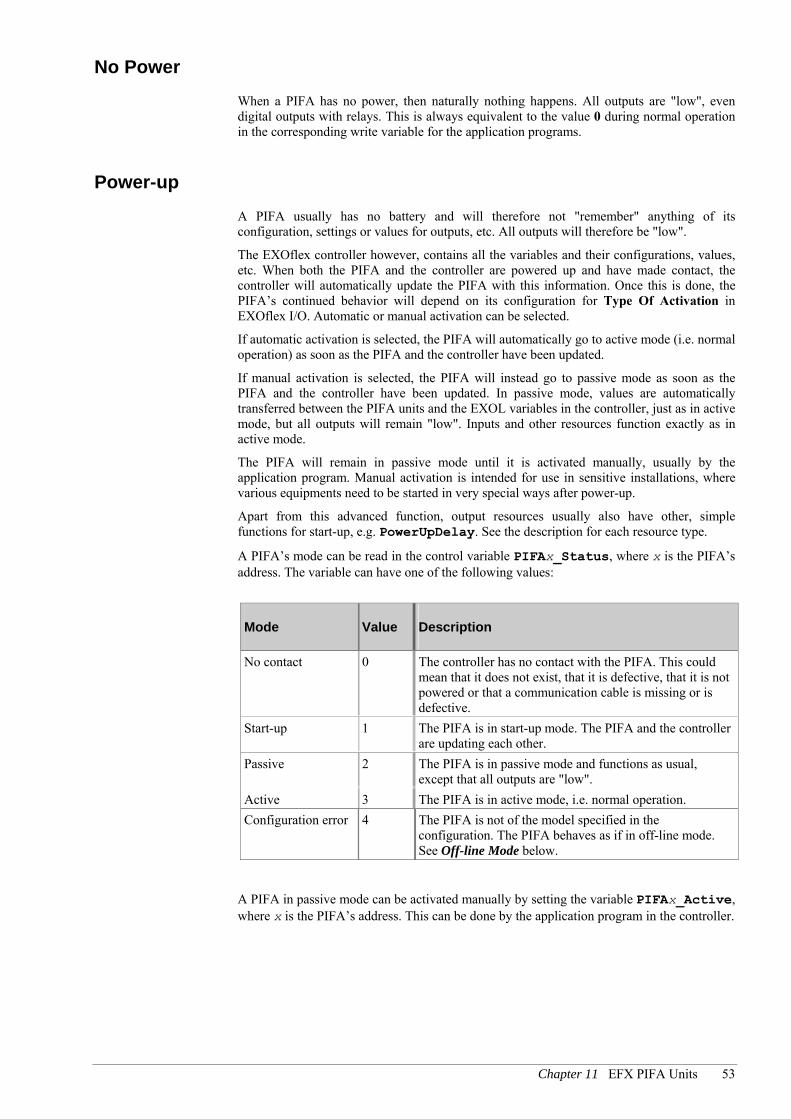
A PIFA’s mode can be read in the control variable PIFAx_Status, where x is the PIFA’s address. The variable can have one of the following values:
Mode Value Description
No contact 0 The controller has no contact with the PIFA. This could mean that it does not exist, that it is defective, that it is not powered or that a communication cable is missing or is defective.
Start-up 1 The PIFA is in start-up mode. The PIFA and the controller are updating each other.
Passive 2 The PIFA is in passive mode and functions as usual, except that all outputs are "low".
Active 3 The PIFA is in active mode, i.e. normal operation. Configuration error 4 The PIFA is not of the model specified in the
configuration. The PIFA behaves as if in off-line mode. See Off-line Mode below.
A PIFA in passive mode can be activated manually by setting the variable PIFAx_Active, where x is the PIFA’s address. This can be done by the application program in the controller.

54 Part III EXOflex Software
Off-line Mode Off-line mode means that the PIFA has power, but no contact with the controller. This mostly happens for a PIFA in an expansion house or in an external display PIFA if the cable between the units is missing or defective, or if the processor house has no power.
As the PIFA has power it can continue to operate, but it must work entirely without instructions from the application program. The only point of interest (for normal PIFA-units) is the mode for the outputs.
A PIFA that goes into off-line mode directly after power-up cannot do anything, as it has no battery and will behave as if in a powerless state, i.e. the outputs will remain "low".
A PIFA that goes into off-line mode directly from normal operation will remember all of its settings and values, as long as it has power itself. The behavior for each output in this case can be configured. You can either let the output retain the value it had when it entered off-line mode, or you can let it go "low" directly.
When the PIFA regains contact with the controller, they will first of all update each other. Once this is done, the PIFA’s continued behavior will depend on the configuration for the type of activation, in exactly the same way as for power-up.
Communication Disturbance
Communication between a controller and its PIFA units is via the EFX-channel. Communication within the processor house cannot, in principle, be disturbed.
Communication with PIFA units in an expansion house or with an external display PIFA however, is via a cable. This communication can be disturbed. Naturally, the protocol used in the EFX channel contains mechanisms that ensure that disturbance is detected and that the query is automatically sent again. If there is severe disturbance however, communication can sometimes be knocked out in all retries.
If there is long-term communication disturbance (several seconds), the PIFA will go to off-line mode.
Whatever happens, the controller and the PIFA will continue to update each other as soon as communication is re-established. The continued behavior will depend on the configuration for the type of activation, in the usual way.
Spontaneous Warm-start
All the operating systems involved contain security systems, both in the software and hardware, which monitor their function. If something serious occurs, e.g. because of an error in an operating system, there will be an automatic re-start, i.e. a spontaneous warm-start.
When this occurs, the controller and the PIFA will immediately update each other again. Continued behavior will depend on the configuration for the type of activation, in the usual way.
Other Considerations
PIFAos Each EFX-PIFA has its own CPU with the operating system PIFAos. The revision of PIFAos for each PIFA can be read from a number of EXOL-variables, as below:

Chapter 11 EFX PIFA Units 55
Type Variable Description
X PIFAx_RevisionMajor Integer part of the PIFAos revision.
X PIFAx_RevisionMinor Decimal part of the PIFAos revision.
X PIFAx_RevisionBranch Branch part of the PIFAos revision.
I PIFAx_RevisionNumber Incremental part of the PIFAos revision.
x is the PIFA’s address.
Example: 1.3-1-17
Serial Number
The serial number for each PIFA can be read in the variable PIFAx_SerialNumber, where x is the PIFA’s address.

56 Part III EXOflex Software
Chapter 12 The Processor and the Power-PIFA
Each processor unit has one or more processors. The processor furthest to the left in the house is called the main processor. This handles the resources in the power-PIFA and also has a special role in handling the serial ports.
EXOreal Each processor has a CPU with the real-time operating system EXOreal, which is the heart of the controller. EXOreal runs all the application programs etc. The EXOreal CPU is of the type C515C, which is a variant of Intel’s 8051 core. This CPU is 100% software compatible with the processors used in other EXO controllers: the 8032 and the 80522. It also has the same performance, i.e. equivalent to 22 MHz clock frequency.
The EXOreal revision can be read from a number of system variables in the usual way. See the document EXOreal.
The EXOreal CPU has 480 kByte expanded memory and 32 kByte conventional memory for application programs. The amount of free memory can be read with e.g. EXOtest in the usual way. See also the document Troubleshooting controllers with EXOtest.
The EFX Channel Each processor also has an EFX channel, which is handled by another CPU, using the real-time operating system EFXos.
In a house with only one processor, the EFX channel runs to all the PIFA units in the house and to contacts on the power-PIFA, where the EFX channel can be connected via a cable to an expansion house or an external display PIFA.
In houses with several processors, the EFX channel runs from each processor to the PIFA units in the same section as the processor and to sections to the right of that, up to the next processor.
The EFXos revision can be read from the system variables EFXosRevMajor, EFXosRevMinor, EFXosRevBranch and EFXosRevNumber.
Type Name QPac QLN Cell Nor Ver T Description
X EFXosRevMajor QEXOflex 239 10 - 2.8 - Integer part of EFXos version.
X EFXosRevMinor QEXOflex 239 11 - 2.8 - Decimal part of EFXos version (multiplied by 10).
X EFXosRevBranch QEXOflex 239 12 - 2.8 - Branch part of EFXos revision.
I EFXosRevNumber QEXOflex 239 13 - 2.8 - Incremental part of EFXos revision.

Chapter 12 The Processor and the Power-PIFA 57
Hardware Clock Each processor has a hardware clock that ensures that the real-time clock runs with high accuracy, even when the processor house has no power. Transfer between the hardware clock and the software clock in EXOreal occurs completely automatically.
Built-in Battery The power-PIFA contains a battery that preserves the contents of the processors’ memory and keeps the hardware clock running when the house has no power.
The battery is easily replaced by pulling out the power-PIFA. Each processor has a small current reserve that can keep the memory and hardware clock running for approximately 30 minutes, without the power-PIFA.
The power-PIFA also monitors the battery voltage. When the voltage drops too low, a LED in the front panel is lit. Furthermore, the system variable BattFail is set in the house’s main processor. See also the document EXOreal.
External Battery (Option 9035) The main power PIFA EP1011 can be fitted with option 9035, which makes it possible to connect an external battery as an alternative power source for the controller. This battery is intended to complement the normal power supply to the controller, so that the controller can continue working as normal during a power failure.
The main power PIFA has certain indicators regarding the external battery and the power supply. These are found in the system variable ExtBattery and is shown with LEDs on the front panel of the main power PIFA.
Line Failure (LF), bit #0, indicates that the normal external power supply is not working, i.e. the controller is being powered by the external battery. When the bit is set to zero, the controller is powered as normal.
Battery Low (Lo), bit #1, indicates that the voltage from the external battery is running low. If this bit is set when the external battery is powering the controller, the battery can only continue to power the controller for a short while. You may however assume that the time is long enough for sending an alarm.
Battery Failure (BF), bit #2, indicates that the external battery is out of function, e.g. completely drained or erroneously connected. This can of course only be indicated while the normal power supply is working.
Type Name QPac QLN Cell Nor Ver T Description
X ExtBattery QSystem 241 29 - 2.8 - Handling of external battery (Option 9035). Bit # 0 = Normal external power supply out of function. Bit #1 = External battery, low voltage. Bit #2 = External battery out of function.

58 Part III EXOflex Software
Digital Inputs and Outputs (on the Main Power PIFA) The main power PIFA has a few simple digital inputs and outputs.
The main power PIFA is not an EFX PIFA, which means that the inputs and outputs do not work in the same way as in other PIFA units. Instead these are handled directly by EXOreal, as in other, non-EXOflex-controllers, i.e. with the system variables DIn and DQn. See also the document EXOreal.

Chapter 13 Communication 59
Chapter 13 Communication
Serial ports are handled in the same way as in non EXOflex controllers, directly by EXOreal. In software respects, each EXOflex controller always has 3 ports. Communication is handled by the application program in the traditional way, which is described in detail in the document EXOreal.
The differences in EXOflex are mechanical and electrical, i.e. how the ports are connected in the house, both between the processors in the house and to the various PIFA units.
Electrical Formats All ports can be used for RS232 or RS485.
RS485 All RS485 ports have a complete set of signals, i.e. N, A, B and E.
RS232 The ports have support for various sets of signal for RS232, according to the below:
Port 1: RxD, TxD and RTS.
Port 2: RxD, TxD, RTS and CTS.
Port 3: RxD, TxD, RTS, CTS, DTR, DSR, RI and DCD.
Connections
The Main Processor The main processor is the one furthest to the left in a processor house. Descriptions of how to connect these ports follow below.
Port #1 Port #1 always connects to the power-PIFA in PIFA position 1. There is no configuration for the actual connection.
Port #2 The main processor’s port #2 can be connected in several ways.
Internally, port #2 is connected to port #1 on the other processors in the house. In houses with several processors, this should be used for communication between the processors (i.e. the controllers). This connection is always present, irrespective of the configuration.

60 Part III EXOflex Software
Port #2 can also be connected to a communication-PIFA in any position in the house. The position is selected with the system variable Control_Port_2, by assigning it the position address for the desired PIFA. Assigning it the value 0 will mean that it is not connected.
In houses with several processors, port #2 can be used for internal EXOline communication in the house and for external controllers via a communication PIFA, both at the same time.
It is possible to mount an option card alongside the communication PIFA in the same position. The port’s connection is selected with bit #1 in the system variable Signal_Port_2. When the bit is reset, the port is connected directly to the external connector on the communication PIFA. When the bit is set, it is connected via the option card and onwards to its external connector on the communication PIFA.
Normally, the port’s connection is configured statically, but for special applications it is possible to change the connection dynamically. This is not suitable for EXOline communication, but rather for communication using special protocols with low performance requirements, e.g. meter reading.
Port #3 Port #3 is always connected to PIFA position 2, if a communication PIFA is used in that position.
It is possible to mount an option card with the communication PIFA, in the same position. Select the port’s connection with bit #1 in the system variable Signal_Port_3. When the bit is reset, the port is connected directly to the external connector on the communication PIFA. When the bit is set, it is connected via the option card and onwards to its external connector on the communication PIFA.
The application program can determine whether or not the external connector on the communication PIFA is connected via a cable to other equipment. This is indicated by bit #3 in Signal_Port_3. If there is a connection present, this will be set.
Other Processors
Port #1 Port #1 is always connected to port #2 in the main processor. The port cannot be connected externally.
Port #2 Port #2 can only be connected to a communication PIFA in one of the two PIFA positions in the same section as the processor. Select the position with the system variable Control_Port_2, by assigning it the position address for the desired PIFA. The value 0 will mean that it is not connected.
It is possible to mount an option card with the communication PIFA, in the same position. Select the port’s connection with bit #1 in the system variable Signal_Port_2. When the bit is reset, the port is connected directly to the external connector on the communication PIFA. When the bit is set, it is connected via the option card and onwards to its external connector on the communication PIFA.
Port #3 Port 3 is always connected to the PIFA position closest to and "under" the processor, if using a communication PIFA in that position.

Chapter 13 Communication 61
It is possible to mount an option card with the communication PIFA, in the same position. Select the port’s connection with bit #1 in the system variable Signal_Port_3. When the bit is reset, the port is connected directly to the external connector on the communication PIFA. When the bit is set, it is connected via the option card and onwards to its external connector on the communication PIFA.
The application program can detect whether or not the external connector on the communication PIFA is connected via a cable to other equipment. This is indicated by bit #3 in Signal_Port_3. If there is a connection present, this will be set.
System Variables
Type Name QPac QLN Cell Nor Ver T Description
X Signal_Port_2 QCom 248 45 0 2.4 - Control signals in port #2.
X Signal_Port_3 QCom 248 46 0 2.4 - Control signals in port #3.
X Control_Port_2 QCom 248 55 2 2.8 - Determines which PIFA position port #2 will connect to.

62 Part III EXOflex Software
Chapter 14 Digital Inputs
General There are two standardized types of digital inputs, in software respect normal and advanced. They have the following functions:
Normal Inputs A normal digital input has the following functions:
A digital filter, which always filters out pulses shorter than 4.5 ms and always registers pulses longer than 9 ms.
The signal can be inverted.
Configurable on/off delays, in the interval 0.1 to 3000 seconds, with separate variables for filtered values and raw values.
Run time logging with the resolution 1 second. The function has double counters (with normal or very high resolution respectively). The counters can be set independently of each other by the application program.
A transient flag that is set each time a changed value is registered that can be used to register short pulses in a Task.
Advanced Inputs An advanced digital input has the following functions:
All the functions found in a normal input, but with a faster digital filter, which always filters out pulses shorter than 2.25 ms and always registers pulses longer than 4.5 ms.
Pulse counting up to 110 pulses per second. The function has double counters (with normal and very high resolution respectively). The counters can be set independently of each other by the application program.
Pulse speed measuring up to 110 pulses per second.
Option to automatically convert pulse counting and pulse speed measuring to application units (scaling).
Function Using the configuration attribute Type, the digital input’s function is selected.
With the type Normal, the input’s level is continuously indicated by the variable DI. The indication can be delayed by using the attributes OnDelay and OffDelay respectively, which specify the on and off delays in seconds, in the interval 0.1 to 3000 seconds.
It is also possible to invert the signal, i.e. a low signal to the hardware will be seen as high in the software and vice versa. The inversion is not absolute until the first reading of the level in the hardware. The function is activated with the attribute Invert Signal.
For troubleshooting (or other purposes), the input’s momentary value (raw value) is indicated in the variable DIRaw.

Chapter 14 Digital Inputs 63
Run-time Logging Digital inputs have a built-in function for run time logging. The function is active if Type = Runtime Counter.
The function logs the time the input is high. The desired unit can be configured in the variable TimeUnit and is given in seconds. By default, run time is calculated in hours (3600 seconds), but always uses the resolution 1 second.
The time logged is counted up automatically in the variable DICount. The application program can, at any time, set the value of DICount to some other value. The input continues to count from the entered value.
By configuring Two Counters = Yes there will be two separate variables for run time logging: DICount and DICount2. These are intended for logging run time at different time periods. Both can be set (or reset) independently of each other by the application program.
DICount has high resolution, with approximately 12 figure accuracy, which is equivalent to >30 000 years. DICount2 has a more moderate resolution, with approximately 6 figure accuracy, which is equivalent to 11 days (24h periods). DICount2 can advantageously be used for data assimilation to Logging, for e.g. logging run time per 24h. Logging can be configured to log DICount2 directly to achieve this.
When run time logging is active, the input’s value is indicated simultaneously in DI and DIRaw, just as during normal function.
Pulse Counting
Normal Inputs Pulse counting on normal digital inputs can be done with an application program, if the pulses are not coming too quickly. It is then possible to catch very short pulses (> 9 ms) in a relatively slow program, with the help of the transient flag.
Each time the input’s value changes, this is indicated in the variables DI and DIRaw. The input’s transient flags are also set each time the value changes. By reading the transient flag in the program, even very short pulses can be counted. EXOdesigner provides a ready-made controller object Pulse Counting, which is suitable for this purpose.
The shortest time allowed between pulses is determined by the transfer between the PIFA and EXOreal, as well as by the application program’s scan cycle.
Example: With 7 PIFA units and a program with the scan cycle 500 ms, the shortest period allowed between the pulses is: 20 + 7*1.4 ms + 500 ms = 530 ms. This applies if all the PIFA units have the same priority. If this is too slow, you can increase the priority for some of the PIFA units and decrease it for others.
Advanced Inputs Advanced digital inputs have a built-in function for pulse counting. The function is active if Type = Pulse Counter or Pulse Counter+Rate.
The function counts all pulses (> 4.5 ms) and automatically counts up the variable DICount at regular intervals. Pulses arriving at speeds of up to 9 ms can be counted. The function can also automatically convert the value to application units. The number of pulses is multiplied with the value Scale before DICount is updated.
The application program can, at any time, set the value of DICount to a desired value. The input will then continue to count from the entered value.

64 Part III EXOflex Software
By configuring Two Counters = Yes you will get two separate variables with pulse counting: DICount and DICount2. These are intended for pulse counting at different resolutions. Both can be set (or reset) independently of each other by the application program.
DICount has high resolution, with approx. 12 numbers accuracy, i.e. 1 billion pulses. DICount2 has a more moderate resolution, with approx. 6 numbers accuracy, i.e. 1 million pulses. DICount2 can advantageously be used for data assimilation to Logging, for e.g. logging the number of pulses per day (24h). Logging can be configured to log DICount2 directly to achieve this function.
When pulse counting is active, the input’s status is not indicated in DI and DIRaw. If this is required, you must configure Type with a numerical value that activates the function. Note however, that if the pulse speed is high, this will put a great load on the EXOreal processor.
Pulse Rate Measuring
Normal Inputs Pulse rate measuring (i.e. frequency measuring) on normal digital inputs can be done with an application program, if pulses are not coming too quickly. It is then possible to capture very short pulses (> 9 ms) in a relatively slow program, with the help of the transient flags for DI or DIRaw, in the same way as for pulse counting.
EXOdesigner has a ready-made controller object for pulse rate measuring, Pulse Counting, which is suitable for this purpose.
Advanced Inputs Advanced digital inputs have a built-in function for pulse rate measuring (i.e. frequency measuring). The function is active if Type = Pulse Counter+Rate.
Pulse rate is indicated continuously in the variable DIRate.
The function counts all pulses (> 4.5 ms), even if they are coming very quickly (> 9 ms). The pulse rate is calculated each time that NoOfPulses pulses are received. If not enough pulses have been received in the period MaxTime (normally 1 minute), the rate is calculated anyway.
You can configure the desired unit in the variable TimeUnit, in seconds. With e.g. TimeUnit = 60, the pulse rate is calculated as pulses/minute. Furthermore, this function can also automatically convert the values to application units. The pulse rate is multiplied with the value Scale before DIRate is updated.
When pulse rate measuring is active, the input’s status is not indicated in DI or DIRaw. If this is required, you must configure Type with a numerical value that activates the function. Note however, that if the pulse rate is high, this will put a great load on the EXOreal processor.

Chapter 14 Digital Inputs 65
Function Diagram Figure 35. The functions of a digital input shown schematically.
CountType
DIRate
Pulse
RunTime
HardwareHysteresis(9 ms)
Hysteresis(4.5 ms)
DIRaw
OnDelay & OffDelay
DI
RunTimeCounter
PulseCounter
DICount
DICount2
RateCounter
Advancedfunctions
Scale
Filter
Scaling
Scale & TimeUnit
Scaling
TimeUnit
ScalingFilter
Filter
InvertSignal
Configuration A digital input has the following configuration attributes:
Attribute Normal Description
Type Normal Type of function for the digital input. Specified as one of the following alternatives: Off [0], Normal [3], Run time Counter [83], Pulse Counter [16], Pulse Counter+Rate [144]. Corresponds to the bits 0, 1, 4, 6 and 7 in the variable DIMode. Arbitrary combinations can be configured using a numerical value.
Invert Signal No Specifies if the signal will be inverted, i.e. a low signal to the hardware will be high in the software and vice versa.
Two Counters No Used when two variables are required, for pulse counting or run time logging, i.e. DICount and DICount2.
Corresponds to bit #5 in the variable DIMode.
OnDelay 0.0 On-delay. Given in seconds in the interval 0.0 to 3000.0 seconds.
OffDelay 0.0 Off-delay. Given in seconds in the interval 0.0 to 3000.0 seconds.
TimeUnit 3600 Time unit for calculation of pulse speed or run time logging. Given in seconds in the interval 1 to 32000 seconds.
Scale (Advanced inputs)
1.0 Scaling factor for converting pulse counting and pulse speed measuring to application units.
NoOfPulses (Advanced inputs)
1
Number of pulses after which the pulse speed will be calculated and transferred. The period must, however, have been at least 1 second in duration. The number of pulses is given in the interval 0 to 250 pulses. NoOfPulses = 0 means that the pulse speed is calculated solely by time, with the interval MaxTime.
MaxTime (Advanced inputs)
60 Maximum time allowed to elapse before the pulse speed will be calculated, even if not enough pulses have been received. Specified in seconds in the interval 1 to 32000 seconds.

66 Part III EXOflex Software
Variables A digital input has the following variables:
Type Variable Nor Class Description
L DI - Read The input’s current value, after any on/off delays.
L DIRaw - Read The input’s current value, before any on/off delays.
X DIMode 3 Param. Configuration of the digital input’s mode: Bit #0: The variable DI is active. Bit #1: The variable DIRaw is active. Bit #4: The variable DICount is active. Bit #5: The variable DICount2 is active. Bit #6: Type of counting in DICount and DICount2: 0 = Pulse counting, 1 = Run time logging (Advanced).Bit #7: The variable DIRate is active (Advanced inputs).
R DIOnDelay 0.0 Param. On-delay. Specified in seconds in the interval 0.0 to 3000.0 seconds.
R DIOffDelay 0.0 Param. Off-delay. Specified in seconds in the interval 0.0 to 3000.0 seconds.
R DICount 0.0 R/W Run-time or pulse counter, possibly converted to application unit.
R DICount2 0.0 R/W Run-time or pulse counter, possibly converted to application unit.
R DITimeUnit 3600 Param. Time unit for calculating pulse rate or run-time. Specified in seconds in the interval 1 to 32000 seconds.
R DIScale
(Advanced inputs)
1.0 Param. Scaling factor for converting pulse counting and pulse rate measuring to application unit.
R DIRate
(Advanced inputs)
- Read Pulse rate, possibly converted to application unit.
X DINoOfPulses
(Advanced inputs)
1
Param. Number of pulses for which the pulse speed will be calculated and transferred. The period must, however, have been at least 1 second in duration. The number of pulses should be given in the interval 0 to 250 pulses. NoOfPulses = 0 means that the pulse speed is calculated solely by time, with the interval MaxTime.
R DIMaxTime
(Advanced inputs)
60 Param. Maximum time allowed to elapse before the pulse speed will be calculated, even if not enough pulses have been received. Specified in seconds in the interval 1 to 32000 seconds.
DI is the digital input’s resource name, which normally is DOp_r, but this can freely be configured in PIFA I/O. p is the PIFA’s address, which is a numerical value from 0 to 31. r is the resource’s number in the PIFA, which is a numerical value from 1 and upwards.
Chapter 15 Digital Outputs 67
Chapter 15 Digital Outputs
General The standardized type of digital outputs has the following functions:
Direct control of the output’s mode.
Configurable on/off delays, in the interval 0 to 30000 seconds, with indication of the output’s momentary status (raw value).
"Manual" control of the output’s mode.
Pulse proportioning, with the resolution 10 ms.
Frequency generation, with the resolution 10 ms.
Possibility to control pulse proportioning and frequency generation directly in application units (scaling).
Configurable handling at power-up.
Possibility to decide the signal’s behavior if the PIFA loses contact with the processor.
Overheating protection, which automatically disconnects the outputs before the electronics get overheated (only for certain models).
Function With the configuration attribute Type you can choose the digital output’s function mode.
In Normal mode, the output’s value can be controlled directly with the variable DO. Changes can be delayed with the help of the attributes OnDelay and OffDelay respectively, which specify on/off delays in seconds in the interval 1 to 30000 seconds.
The output’s mode can also be controlled manually, with the variable DOManAutoSelect:
When DOManAutoSelect = 2, the mode is automatic, i.e. the output’s mode is controlled by the variable DO, as described above.
When DOManAutoSelect = 0 or 1 respectively, the output will be low or high respectively, irrespective of the value of DO.
For PIFA units with physical hand control switches, the output’s mode can also be controlled manually. The function of the hand control switch is superior to its correspondence in the software (the variable DOManAutoSelect). In these PIFA units, there is a variable, DOManAutoStatus, specifying status for the digital output’s hand control modes, from both a software and a hardware point of view:
If the switch is in Auto mode, the configuration of DOManAutoSelect is shown
If the switch is not in Auto, the mode of the switch is shown.
When DOManAutoStatus = 3 and 4 respectively, the output is low and high respectively.
For troubleshooting purposes, the output’s momentary status (raw value) is indicated in the variable DORaw.

68 Part III EXOflex Software
The transfer time from the variable DO to the output’s hardware in the PIFA is determined by the transfer between EXOreal and the PIFA, and by the internal handling in the PIFA (which is 10 ms).
Example: With 7 PIFA units, the total transfer time will be: 20 * 7 + 10 ms = 150 ms. This will apply if all the PIFA units have the same priority. If this is too slow, you can increase the priority for some PIFA units and decrease it for others.
Pulse Proportioning A digital output can generate a pulse proportioning signal automatically. You get this by selecting Type = Pulse Proportion.
A pulse proportioning signal means that you generate a signal with a constant frequency, but with varying pulse lengths (the time when the output is high). The signal’s resolution is 10 ms.
You control the proportioning with the variable DOPulse in percent (i.e. with the value 0–100). The period (the time between pulses) is configured with the attribute PulseTime in seconds, in the interval 0,01 to 300 seconds.
It is possible to control the proportioning with an application unit (instead of 0–100). The pulse proportioning (in percent) is then controlled by DOPulse * Scale.
When the pulse proportioning function is in use, the output’s momentary status is not indicated in DORaw. If this is required, you must configure Type with a numerical value that activates the function. Note however, that if the pulse speed is high, this will put a great load on the EXOreal processor.
The signal can also be controlled manually, according to the below:
When DOManAutoSelect = 2, the mode is automatic, i.e. the signal is controlled by the variable DOPulse, as described above.
When DOManAutoSelect = 0, the output is low, irrespective of the value of DOPulse.
When DOManAutoSelect = 1, the signal is instead controlled by the variable DOManPulse, possibly in an application unit if scaling is used.
Frequency Generation A digital output can generate a frequency signal automatically. This is achieved by selecting Type = Pulse Rate.
Frequency generation means that a signal with constant pulse length (the time when the output is high), but with varying frequency is generated The signal’s resolution is 10 ms.
The pulse speed is controlled by the variable DOPulse in periods/second (Hertz). The pulse length (the time when the output is high) is configured with the attribute PulseTime in seconds, in the interval 0.01 to 300 seconds.
It is possible to control the pulse speed with an application unit (instead of pulses/seconds). The pulse speed is then controlled by DOPulse * Scale.
During frequency generation, the output’s momentary status is not indicated in DORaw. If this is required, you must configure Type with a numerical value that activates the function. Note however, that if the pulse speed is high, this will put a great load on the EXOreal processor.
You can also control the signal manually, according to the following:
When DOManAutoSelect = 2, the mode is automatic, i.e. the signal is controlled by the variable DOPulse as described above.

Chapter 15 Digital Outputs 69
When DOManAutoSelect = 0, the output will have the value 0 in application units.
When DOManAutoSelect = 1, the signal is instead controlled by the variable DOManPulse in application units.
Power-up During power-up, various things will happen depending on the PIFA’s type of activation. The type of activation is configured individually for each PIFA in EXOflex I/O Tool.
Normally, automatic activation is used, which means that the outputs are kept low for the time specified by the attribute PowerUpDelay. When that time has elapsed, the output is immediately set to the value of the variable DO (without regard to OnDelay) or DOPulse, depending on the type of function. Thereafter, it will function as usual.
The outputs are also kept low during manual activation and the whole PIFA ends up in passive mode. This state will persist until the application program "manually" activates the PIFA. When this happens, the output is immediately set to the value of the variable DO (without regard to OnDelay or PowerUpDelay) or DOPulse. Thereafter, it will function as usual.
See also Run Modes on page 52.
Off-line Mode PIFA units in expansion houses can lose contact with the EXOreal processor, if e.g. the cable between the expansion house and the processor house is damaged, or if the processor house loses power. Using the attribute Off-line Action, you can decide what will happen to the output when this occurs.
Using the configuration Off-line Action = Set Signal Low, the output is set low as soon as the contact is lost.
Normally you would use the configuration Off-line Action = Keep Signal. The output value current at the time of the loss of contact will instead remain on the output. For pulse proportioning or frequency outputs, this means that the output will continue to generate pulses on its own.
When contact is re-established, much the same will occur as during power-up, as described above.
See also Run Modes on page 52.
Overheating Protection Certain PIFA models have digital outputs with automatic overheating protection, which automatically disconnects the outputs before the electronics get overheated. This applies to outputs of the type 24V DC.
The protection triggers when the temperature in the electronics rises above 74 ˚C and returns when it falls below 70˚C. The status for the protection is indicated in bit #0 in the variable DOpSumStatus, which is set when the protection is triggered. It will be reset when the protection returns.

70 Part III EXOflex Software
Function Diagram Figure 36. The functions of a digital output shown schematically.
Hardware
DO
OnDelay & OffDelay
Filter
ManAutoSelect
ManAutoSelect
0
DOPulse
DOManPulse Mode PowerUpDelay
Filter
HeatProtection
Filter
DORaw
PulseProp
FreqGen
0
DOManPulse
Scaling
0
1
Non relayoutput
Relayoutput
0
1
Switch
DOManAutoStatus
DO
Configuration A digital output has the following configuration attributes:
Attribute Normal Description
Type Normal Type of function for the digital output. Uses one of the following alternatives: Off [0], Normal [5], Pulse Proportion [2], Pulse Rate [3]. Corresponds to the bits 0-2 in the variable DOMode. Arbitrary combinations can be configured using a numerical value.
OnDelay 0 On-delay. Specified in seconds in the interval 0 to 30000 seconds.
OffDelay 0 Off-delay. Specified in seconds in the interval 0 to 30000 seconds.
PowerUpDelay 0 Automatic on-delay during power-up. Specified in seconds in the interval 0 to 255 seconds.
Off-line Action Keep signal
Determines what will happen to the output’s value in off-line-mode. Specified by one of the following alternatives: Keep signal [0] or Set signal low [128]. Corresponds to bit #7 in the variable DOMode.
Scale 1.0 Scaling factor for conversion to application unit.
PulseTime 1.00 Period for pulse proportioning or pulse length for frequency generation. Specified in seconds in the interval 0.01 to 300 seconds.
Variables A digital output has the following variables:
Type Variable Nor Class Description
L DO 0 Write Controls the output’s value.
L DORaw - Read Indicates the output’s momentary status.

Chapter 15 Digital Outputs 71
X DOMode 1 Param. Configuration of the digital output’s mode: Bit #0-1: 00 = Inactive. 01 = Normal. 10 = Pulse proportioning. 11 = Frequency generation. Bit #2: The variable DORaw is active. Bit #7: Behavior when switching to off-line mode: 0 = The output is retained, 1 = out-signal is set low.
X DOManAutoSelect 2 Param. Determines mode for a “normal” output, as follows: 0 = Manual mode: Off- 1 = Manual mode: On. 2 = Automatic mode (normal run-mode). Determines mode for a “pulsed” output as follows: 0 = Manual mode: 0 in application units. 1 = Manual mode: Controlled by DOManPulse in application units. 2 = Automatic mode: Controlled by DOPulse in application units. 3 = Manual mode: 0 in engineering units. 4 = Manual mode: Controlled by DOManPulse in engineering units.
X DOManAutoStatus - Read For PIFA with physical man/auto switches. The variable specifies status for the digital output’s ManAuto mode (Off sw = 0, On sw = 1, Auto = 2, Off hw = 3, On hw = 4).
R DOOnDelay 0 Param. On-delay in normal operation. Specified in seconds in the interval 0 to 30000 seconds.
R DOOffDelay 0 Param. Off-delay in normal operation. Specified in seconds in the interval 0 to 30000 seconds.
X DOPowerUpDelay 0 Param. On-delay after power-up (and a few other special cases). Specified in seconds, in the interval 0 to 255 seconds.
R DOPulse 0.0 Write Controls frequency or pulse proportioning in automatic mode.
R DOManPulse 0.0 Write Controls frequency or pulse proportioning in manual mode.
R DOScale 1.0 Param. Scaling factor for conversion to application unit, for pulse proportioning or frequency generation.
R DOPulseTime 1.00 Param. Period for pulse proportioning or pulse length for frequency generation. Specified in seconds, in the interval 0.01 to 300 seconds.
X DOpSumStatus - Read Status summary for all digital outputs in the PIFA: Bit #0: Overheating protection triggered.
DO is the digital output’s resource name, normally DOp_r, but this can freely be configured in PIFA I/O. p is the PIFA’s address, which is a numerical value from 0 to 31. r is the resource’s number in the PIFA, which is a numerical value from 1 and upwards.

72 Part III EXOflex Software
Chapter 16 Analog Inputs
General The standardized types of analog outputs have the following functions:
Modes for many different magnitudes and measurement ranges: Voltage, current and various temperature sensors, directly in engineering units.
Built-in filter that filters out noise and hum.
Configurable exponential filter for "softening up" the signal’s movements
Conversion of measured values to application units.
Compensation for cable resistance for measuring of resistance and temperature.
Configuration of signal behavior when outside the measurement range
Priority specifications can be made for all inputs.
Function With the configuration attribute Type you select the analog input’s mode. The following magnitudes and measurement ranges can be selected: 0–10V, 0–200mV, 0–20mA, 0–2000Ω, Pt100 -50 to +15O°C, Pt100 0 to +600 °C, Pt1000, Ni1000 and Ni1000 L&G.
The input’s level is continually indicated in the variable AI. The measured value always first passes a fast integration filter to filter out noise and hum. This filter cannot be configured. You can also filter the value through an exponential filter. The filter’s time constant is configured with the attribute FilterTime. The time constant is equal to the time taken for the value after filtering to reach 63% of the final value when the input is changed in steps.
The value is presented directly in engineering units (according to Type) in the variable AI. You can however, let the analog input convert it to the required application unit automatically. You do this with the attributes Scale and Offset in the following way:
AI = ( Measured value - OffSet ) * Scale
From and including PIFAos 1.1, the scaling function can be selected with the attribute Scaling Function. There are two functions to choose between; the above and the following:
AI = ( Measured value * Scale ) + OffSet
For troubleshooting (or other purposes), the input’s value is also indicated in the variable AIRaw (the raw value) before it passes the exponential filter and is converted to application units.
Compensation for Wire Resistance The analog input can automatically compensate for resistance in wires to temperature sensors. This is achieved by measuring the total resistance in both wires from the controller to the sensor and configuring the measured value directly in Ohm (Ω) in the attribute WireRes.
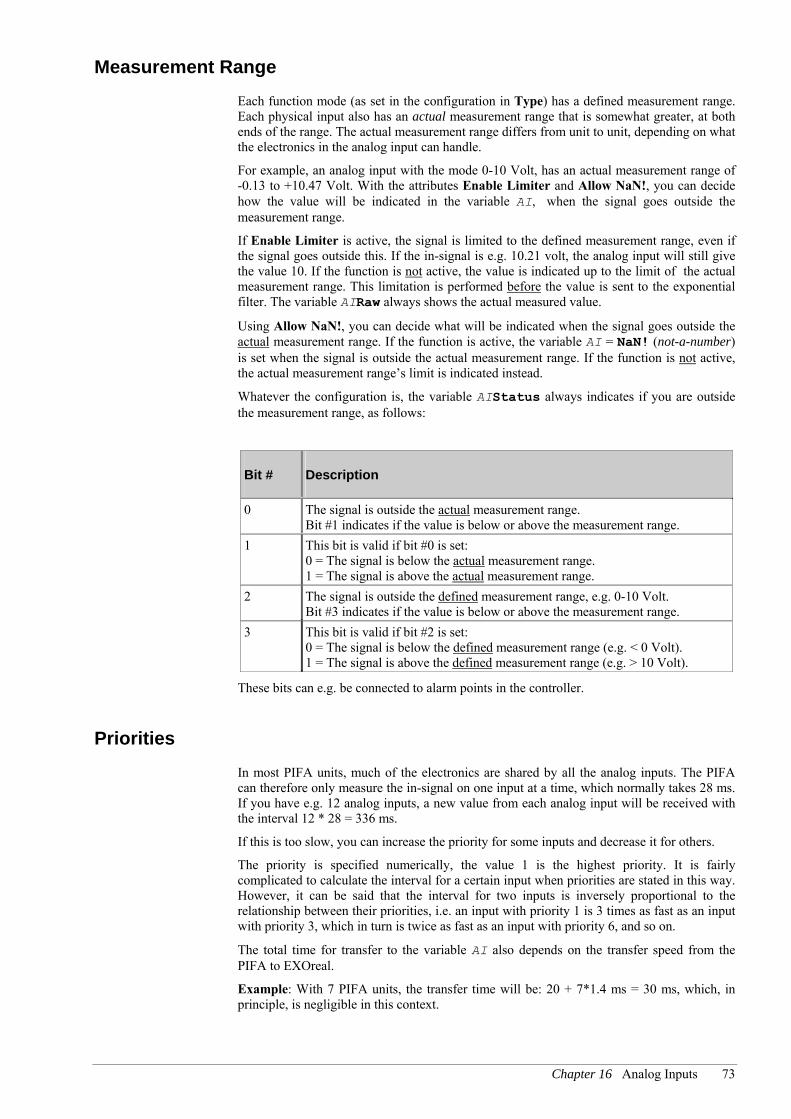
Chapter 16 Analog Inputs 73
Measurement Range Each function mode (as set in the configuration in Type) has a defined measurement range. Each physical input also has an actual measurement range that is somewhat greater, at both ends of the range. The actual measurement range differs from unit to unit, depending on what the electronics in the analog input can handle.
For example, an analog input with the mode 0-10 Volt, has an actual measurement range of -0.13 to +10.47 Volt. With the attributes Enable Limiter and Allow NaN!, you can decide how the value will be indicated in the variable AI, when the signal goes outside the measurement range.
If Enable Limiter is active, the signal is limited to the defined measurement range, even if the signal goes outside this. If the in-signal is e.g. 10.21 volt, the analog input will still give the value 10. If the function is not active, the value is indicated up to the limit of the actual measurement range. This limitation is performed before the value is sent to the exponential filter. The variable AIRaw always shows the actual measured value.
Using Allow NaN!, you can decide what will be indicated when the signal goes outside the actual measurement range. If the function is active, the variable AI = NaN! (not-a-number) is set when the signal is outside the actual measurement range. If the function is not active, the actual measurement range’s limit is indicated instead.
Whatever the configuration is, the variable AIStatus always indicates if you are outside the measurement range, as follows:
Bit # Description
0 The signal is outside the actual measurement range. Bit #1 indicates if the value is below or above the measurement range.
1 This bit is valid if bit #0 is set: 0 = The signal is below the actual measurement range. 1 = The signal is above the actual measurement range.
2 The signal is outside the defined measurement range, e.g. 0-10 Volt. Bit #3 indicates if the value is below or above the measurement range.
3 This bit is valid if bit #2 is set: 0 = The signal is below the defined measurement range (e.g. < 0 Volt). 1 = The signal is above the defined measurement range (e.g. > 10 Volt).
These bits can e.g. be connected to alarm points in the controller.
Priorities In most PIFA units, much of the electronics are shared by all the analog inputs. The PIFA can therefore only measure the in-signal on one input at a time, which normally takes 28 ms. If you have e.g. 12 analog inputs, a new value from each analog input will be received with the interval 12 * 28 = 336 ms.
If this is too slow, you can increase the priority for some inputs and decrease it for others.
The priority is specified numerically, the value 1 is the highest priority. It is fairly complicated to calculate the interval for a certain input when priorities are stated in this way. However, it can be said that the interval for two inputs is inversely proportional to the relationship between their priorities, i.e. an input with priority 1 is 3 times as fast as an input with priority 3, which in turn is twice as fast as an input with priority 6, and so on.
The total time for transfer to the variable AI also depends on the transfer speed from the PIFA to EXOreal.
Example: With 7 PIFA units, the transfer time will be: 20 + 7*1.4 ms = 30 ms, which, in principle, is negligible in this context.

74 Part III EXOflex Software
Function Diagram
Figure 37. The functions of an analog input shown schematically.
Hardware
Exponentialfilter
Filter
AI
AIRaw
Hysteresis
Filter
Compensationfor wireresistance
Wireresistance
Adjustmentfor HW
Calib-ration
Sensorcharacteristic
Lineari-sation
Offset & Scale
Scaling
Min- & max-value limiter
Limiter
Sensorcharacteristic
Lineari-sation
Configuration An analog input has the following configuration attributes:
Attribute Normal Description
Type Normal Type of function for analog input. Specified with one of the following alternatives: Off [0], 0–10V [9], 0–200mV [10], 0–20 mA [11], 0–2000 Ohms [4], Pt100 -50 to +15O°C [5], Pt100 0 to +600°C [12], Pt1000 [1], Ni1000 [8], Ni1000 L&G [2].
Enable Limiter No Specifies if the value from the analog input will be limited to the defined measurement range (according to the configuration of Type). Corresponds to bit #6 in the variable AIMode.
Allow NaN! No Specifies if the value from the analog input will be not-a-number (NaN!) when the signal goes outside the actual measurement range. Corresponds to bit #7 in the variable AIMode.
Priority 8 The analog input’s priority (i.e. how often its value is updated). Specified as a numerical value in the interval 1 to 32, where 1 is the highest priority.
WireRes 0.00 Wire resistance for measuring resistance and temperatures. Specified in Ohm in the interval 0.00 to 300.00 Ohm.
Scaling Function 0 The type of scaling function for converting measured value to application units is specified with one of the following alternatives: (value-Offset)*Scale [0], (value*Scale)+Offset [2].
Offset 0.0 Offset for converting measured values to application units.
Scale 1.0 Scaling factor for converting measured values to application units.
FilterTime 0 Time constant for exponential filter. The value 0 means that the filter is off. Specified in seconds in the interval 0 to 30000 seconds.

Chapter 16 Analog Inputs 75
Variables An analog input has the following variables:
Type Variable Nor Class Description
R AI - Read The input’s current value, after any limiting, scaling, filtering, etc.
R AIRaw - Read The input’s current value, before any limiting, scaling, filtering, etc.
X AIType 9 Param. Configuration of the analog input’s signal type: 0 = Inactive, 1 = Pt1000, 2 = Ni1000 L&G, 4 = 0–2000Ω, 5 = Pt100 -50 to +15O°C, 8 = Ni1000, 9 = 0–10 V, 10 = 0–200 mV, 11 = 0–20mA , 12 = Pt100 0 to +600°C.
X AIMode 1 Param. Configuration of the analog input’s behavior: Bit #0: The variable DIRaw is active. Bit #1: Alternative scaling function selected. Bit #6: The value is limited to the defined measurement range.Bit #7: The value will be NaN! outside the actual measurement range.
X AIStatus 0 Read The analog input’s status: Bit #0: Signal is outside the actual measurement range. Bit #1: 0 = Below, 1 = Above the actual measurement range.Bit #2: Signal is outside the defined measurement range. Bit #3: 0 = Below, 1 = Above the defined measurement range.
X AIPriority 8 Param. The analog input’s priority (i.e. how often its value is updated).
R AIWireRes 0.0 Param. Wire resistance for measuring resistances and temperatures. Specified in Ohms in the interval 0.00 to 300.00 Ohms.
R AIOffset 0.0 Param. Offset for converting measured values to application units.
R AIScale 1.0 Param. Scaling factor for converting measured values to application units.
R AIFilterTime 0 Param. Time constant for exponential filter. The value 0 means that the filter is off. Specified in seconds in the interval 0 to 30000 seconds.
AI is the digital output’s resource name, normally AIp_r, but this can freely be configured in PIFA I/O. p is the PIFA’s address, a numerical value from 0 to 31. r is the resource’s number in the PIFA, a numerical value from 1 and upwards.

76 Part III EXOflex Software
Chapter 17 Analog Outputs
General The standardized types of analog outputs have the following functions:
Direct control of the output’s mode.
Control of the signal in application units.
"Manual" control of the output’s mode.
Automatic, gradual rise when the signal changes.
Configurable behavior for power-up.
Possibility to specify the signal’s behavior if the PIFA loses contact with the processor.
Function The output’s value is controlled directly with the variable AO, normally in engineering units. You can however, choose to control the signal in the desired application unit. This is done with the attributes Scale and Offset and is done in the following way:
Out-signal = (AO * Scale) + Offset
With the configuration attribute Ramp, you can configure an automatic, gradual rise of the out-signal. You specify how fast the out-signal shall change per second, always in engineering units.
You can also control the signal manually, according to the below:
When AOManAutoSelect = 2, the mode is automatic, i.e. the signal is controlled by the variable AO, as described above.
When AOManAutoSelect = 0, the output has the value 0 in application units.
When AOManAutoSelect = 1, the signal is instead controlled by the variable AOMan, in application units.
For troubleshooting, the output’s momentary status (raw value) is indicated in the variable AORaw, normally in application units. The raw value can be indicated in engineering units, by means of bit #2 in the variable AOMode.
The transfer time from the variable AO to the output’s hardware in the PIFA is determined by the transfer between EXOreal and the PIFA, and by the internal handling in the PIFA (which is 10 ms).
Example: With 7 PIFA units, the total transfer time will be: 20 * 7 + 10 ms = 150 ms. This will apply if all the PIFA units have the same priority. If this is too slow, you can increase the priority for some PIFA units and decrease it for others.
Power-up During power-up, various things will happen depending on the PIFA’s type of activation. The type of activation is configured individually for each PIFA in EXOflex I/O Tool.

Chapter 17 Analog Outputs 77
Normally, automatic activation is used, which means that the outputs are kept low for the time specified by the attribute PowerUpDelay. When that time has elapsed, the output is set to the value of the variable AO. If Ramp is configured, the signal rises gradually to that level. Thereafter, it will function as usual.
The outputs are also kept low during manual activation and the whole PIFA ends up in passive mode. This state will persist until the application program "manually" activates the PIFA. When this happens, the output is set to the value of the variable AO. If Ramp is configured, the signal rises gradually to that level. Thereafter, it will function as usual.
See also Run Modes on page 52.
Off-line Mode PIFA units in expansion houses can lose contact with EXOreal, if e.g. the cable between the expansion house and the processor house is damaged, or if the processor house loses power. Using the attribute Off-line Action, you can decide what will happen to the output when this occurs.
With the configuration Off-line Action = Set Signal Low, the output is set low as soon as contact is lost.
Normally you would use Off-line Action = Keep Signal. The out-signal value current at the time of the loss of contact will then instead remain on the output.
When contact is re-established, much the same will occur as during power-up, as described above.
See also Run Modes on page 52.
Function Diagram Figure 38. The functions of an analog output shown schematically.
AORaw
AOMan
ManAutoSelect
0
AO
PowerUpDelay
Filter
HardwareOffset & Scale
Scaling
Fall- & risetimelimiter
Ramp
AOMan
0
Scaling
Mode
Application Unit
Engineering Unit
Configuration An analog output has the following configuration attributes:
Attribute Normal Description
PowerUpDelay 0 Automatic on-delay at power-up. Specified in seconds in the interval 0 to 255 seconds.

78 Part III EXOflex Software
Raw value Mode Application unit
Sets the display mode for the AORaw variable. One of the following alternatives can be set: Off [0], Application unit [2], Engineering unit [6]. Corresponds to bit #1 and bit #2 in the AOMode variable.
Off-line Action Keep signal Determines what will happen with the output’s value in off-line mode. Specified by one of the following alternatives: Keep signal [0] or Set signal low [128]. Corresponds to bit #7 in the variable AOMode.
Offset 0.0 Offset for converting to application unit.
Scale 1.0 Scaling factor for converting to application unit.
Ramp 0.00 Maximum permitted change of out-signal per second, directly in engineering units.
Variables An analog output has following variables:
Type Variable Nor Class Description
L AO 0 Write Controls the value of the output.
L AORaw - Read Indicates the output’s momentary status.
X AOMode 3 Param. Configuration of the analog output’s mode: Bit #0: The analog output is active. Bit #1: The variable AIRaw is active. Bit #2: Type of value in the variable AORaw.
0 = Application units, 1= Engineering units. Bit #7: Behavior when going to off-line mode. 0 = Out-signal retained, 1 = The output is set low.
X AOManAutoSelect 2 Param. Determines mode, as below: 0 = Manual mode: 0 in application units. 1 = Manual mode: Controlled by AOMan in application units. 2 = Automatic mode: Controlled by AO in application units. 3 = Manual mode: 0 in engineering units. 4 = Manual mode: Controlled by AOMan in engineering units.
X AOPowerUpDelay 0 Param. On-delay after power-up (and a few other special cases). Specified in seconds in the interval 0 to 255 seconds.
R AOMan 0.0 Write Controls the output’s value in manual mode.
R AOOffset 0.0 Param. Offset for converting to application units.
R AOScale 1.0 Param. Scaling factor for converting to application units.
R AORamp 0.00 Param. Maximum permitted change of out-signal per second, directly in engineering units.
AO is the analog output’s resource name, normally AOp_r, but this can freely be configured in PIFA I/O. p is the PIFA’s address, a numerical value from 0 to 31. r is the resource’s number in the PIFA, a numerical value from 1 and upwards.

Chapter 18 The External Display 79
Chapter 18 The External Display
The external display is an independent PIFA-unit, which connects to a processor house via the EFX-channel. It has the following resources:
An LCD display with 2 x 20 characters, and software controlled background lighting and viewing angle. The display can show considerably more national characters than the model 5540 for Icelandic, French, Spanish, Italian, Turkish, etc. See below.
20 keys as opposed to 10 in the earlier system. All double functions on the keys have been removed. You then have the following keys [0] to [9], [↑], [↓], [←], [→], [+], [-], [↵], [ ], [.] and [C]. The keys can also generate a click-sound when pressed.
Built-in beeper.
LED in the key [↵] (LED_Num) and a separate alarm LED (LED_Ala). The counterparts to the LED’s in the keys [+] and [-] have been removed. Also, there are a further two LED’s indicating supply voltage and EFX-contact respectively.
2 general digital inputs.
1 general digital output with relay, for e.g. a lamp or external beeper.
The external display is a true EFX-PIFA, but to make it as compatible as possible with non-EXOflex-controllers, most of its functions are still exposed directly by EXOreal. The exceptions are the digital inputs and outputs, which are exposed as full EXOflex-resources, as described in Chapter 14 Digital Inputs and Chapter 15 Digital Outputs
Only one external display can be connected at a time and it always has the address 0.
In normal applications, the external display is not handled directly in the application programs. Instead you use the ready-made controller functions Display, Station Handler and Time Schedules Display. See also Chapter 20 Applications.
The Display The display is handled as in non-EXOflex-controllers, i.e. with the EXOL instruction Print and the system variables CursorPos, DisplayMode, DispTimeOutLatch, DispTimeOut and DispAngle. See also the document EXOreal.
The character set however, does differ from non-EXOflex-controllers. There are considerably more national characters for various European languages. A complete table of these can be found in Character Sets on page 82.
Keypad The keypad is handled as in non-EXOflex-controllers, i.e. primarily by the system variables Key_No and New_Key. There are however, several new keys. For each new key there is a new key code and a new system variable.
Using the system variable KeySound you can choose if the external display will emit a click-sound each time a key is pressed.
The new system variable DisplayInfo allows an application program to check which type of keypad the controller has.

80 Part III EXOflex Software
Key Codes The keys have the following codes:
Key Key_No
[0] 48 [1] 49 [2] 50 [3] 51 [4] 52 [5] 53 [6] 54 [7] 55 [8] 56 [9] 57 [.] 46 [C] 27 [↵] 13
[↑] 30
[↓] 31
[←] 29
[→] 28 [+] 43 [-] 45 [ ] 7
System Variables
Type Name QPac QLN Cell Nor Ver T Description
X DisplayInfo QDisp 249 3 - 2.8 - Information about the external display. Bit #0: Keypad type (0 = 10 keys, 1 = 20 keys).
X Key_No QDisp 249 31 - 2.0 - Key code for latest key pressed
L New_Key QDisp 249 30 - 2.0 - Set when a key is pressed
X KeySound QDisp 249 4 1 2.8 - Type of key sound: 0 = None, 1 = Click
L Key_0 QDisp 249 32 - 2.0 - Indication for key [0]
L Key_1 QDisp 249 33 - 2.0 - Indication for key [1]
L Key_2 QDisp 249 34 - 2.0 - Indication for key [2]
L Key_3 QDisp 249 35 - 2.0 - Indication for key [3]
L Key_4 QDisp 249 36 - 2.0 - Indication for key [4]
L Key_5 QDisp 249 37 - 2.0 - Indication for key [5]
L Key_6 QDisp 249 38 - 2.0 - Indication for key [6]
L Key_7 QDisp 249 39 - 2.0 - Indication for key [7]
L Key_8 QDisp 249 40 - 2.0 - Indication for key [8]
L Key_9 QDisp 249 41 - 2.0 - Indication for key [9]
L Key_Dot QDisp 249 14 - 2.8 - Indication for key [.]
L Key_Clr QDisp 249 15 - 2.8 - Indication for key [C]

Chapter 18 The External Display 81
L Key_Enter QDisp 249 16 - 2.8 - Indication for key [↵]
L Key_Up QDisp 249 17 - 2.8 - Indication for key [↑]
L Key_Down QDisp 249 18 - 2.8 - Indication for key [↓]
L Key_Left QDisp 249 19 - 2.8 - Indication for key [←]
L Key_Right QDisp 249 20 - 2.8 - Indication for key [→]
L Key_Plus QDisp 249 21 - 2.8 - Indication for key [+]
L Key_Minus QDisp 249 22 - 2.8 - Indication for key [-]
L Key_Ala QDisp 249 23 - 2.8 - Indication for key [ ]
LEDs The external display has only 2 LEDs that can be controlled from software: a red alarm LED and an LED in the enter key.
These can be controlled with the system variables LED_Ala and LED_Num, just as in non-EXOflex-controllers. These are however, not suitable for getting the LEDs to flash, as the transfer rate to the external display via the EFX-channel can be slightly too low in controllers with many PIFA-units.
There are therefore two new system variables LEDAlarm and LedEnter that also can be used for controlling the LEDs. Using these variables, you can let the external display do the flashing itself, without putting a load on the application program or the EFX-channel.
The variables can be used in the following ways:
LedAlarm/Enter Description
0 The LED is off 1 The LED is on 2-10 The LED flashes at an interval specified by the value in number of
100 ms. An interval is a complete on/off-cycle!! 255 The LED is controlled by the variable Led_Ala or Led_Num.
System Variables
Type Name QPac QLN Cell Nor Ver T Description
L LED_Ala QDisp 249 42 0 2.0 - Controls the alarm LED directly
L LED_Num QDisp 249 43 0 2.0 - Controls the LED in the enter key directly
X LedAlarm QDisp 249 9 255 2.8 - Advanced control of the alarm LED
X LedEnter QDisp 249 10 255 2.8 - Advanced control of the LED in the enter key
Beeper The beeper is handled as in non-EXOflex-controllers, i.e. with the system variables Beep and Beep_Mode. See also the document EXOreal.

82 Part III EXOflex Software
Character Sets
n= 0 1 2 3 4 5 6 7 8 9
0n CLS2
1n ¤ ‼
2n ¶ § - ↑ ↓ → ←
3n Spc1 ! " # $ % & '
4n ( ) * + , - . / 0 1
5n 2 3 4 5 6 7 8 9 : ;
6n < = > ? @ A B C D E
7n F G H I J K L M N O
8n P Q R S T U V W X Y
9n Z [ \ ] ∧ _ ` a b c
10n d e f g h i j k l m
11n n o p q r s t u v w
12n x y z | ~ ∆ Ç ü
13n é â ä à å ç ê ë è ï
14n î ì Ä Å É æ Æ ô ö ò
15n û ù ÿ Ö Ü ø £ Ø ₧ ƒ
16n á í ó ú ñ Ñ ª º ¿ ®
17n ½ ¼ ¡ « » 18n Á Â À © ¢
19n ¥ ã Ã
20n ¤ ð Ð
21n Ê Ë È i Í Î Ï
22n ¦ Ì Ó ß Ô Ò õ Õ
23n µ þ Þ Ú Û Ù ý Ý ε ´
24n - ± ≥ ≤ ¶ § ÷ , ° .
25n . ¹ ³ ²
1 SPC = Blank space 2 CLS = Clears the display

Chapter 19 TCP/IP 83
Chapter 19 TCP/IP
General
The TCP/IP PIFA-unit is a special PIFA intended for connection to an internal serial port in a processor house. Its task is to carry EXOline-messages in TCP/IP via a computer network, from one controller to another. The connection to the network is via twisted-pair Ethernet.
Communication is always between two or more TCP/IP PIFA-units. The transport via TCP/IP is invisible to the controller, as the communication is translated to and from ordinary serial communication for the controller.
This means that ordinary computer networks, and even the Internet, can be used for communication between and with controllers.
By using TCP/IP PIFA’s, systems can be spread over greater geographic areas with very simple resources. Exploiting the infrastructures already in use for ordinary computers reduces costs for installation.
The PIFA-unit can be used with most types of TCP/IP network, e.g. local area networks, the Internet, etc. It is not however suitable for use in dial-up TCP/IP networks. There are certain security functions that allow it to be used on the Internet, if there are no important security considerations.
Figure 39 shows an example of a system where the controllers communicate with each other with the help of TCP/IP PIFA-units.
Figure 39. System using Ethernet communication.
...
...
...
...
...
Internet
LAN
Sensors & Actuators
EXOFlex unit
NetController The TCP/IP PIFA can also communicate with a product from WHI, called the NetController. There is a special variant of the NetController that supports the EXOline-protocol in the same way as the TCP/IP PIFA.

84 Part III EXOflex Software
TCP/IP Gateway The TCP/IP PIFA can also be used in EXOflex-houses without processors, for creating a TCP/IP Gateway. This can be used independently for converting between EXOline and TCP/IP. See also TCP/IP Gateway on page 129
Network Construction TCP/IP has no concept of master/slave and will, in principle, allow "everybody to communicate with everyone else". This cannot, however, be used to its full extent in the TCP/IP-PIFA-unit, as it is merely a gateway, i.e. a bridge between a TCP/IP network and serial communication.
A controller’s serial port is always either a master or a slave, which is configured in EXOreal in the usual way. The TCP/IP PIFA-unit has no corresponding configuration, but detects itself how it is being used. All communication must go between a master-port and a slave port.
When constructing an ordinary EXOline-network with serial communication, you build a hierarchical network, with one controller at the top, a few more below, etc. This physical and logical structure is reflected in the controller’s addresses (PLA and ELA), to allow configuration of piping through the controllers.
When building a network that uses TCP/IP-communication, it should be designed from the EXOline point of view, with no regard to how it is connected in the TCP/IP-network. You are then constructing a logical EXOline-structure, just as if ordinary serial communication was being used. The controllers’ addresses, the ports’ modes, piping, etc are configured in exactly the same way.
You can design the physical structure of the TCP/IP-network completely independently of the logical construction of the EXOline-network. In most cases, you will not be constructing TCP/IP-networks, but instead using an existing one for the communication between the controllers. There will then usually be a network supervisor who can help with information on how the TCP-IP PIFA-units should be configured.
Security Security in this context means how to protect the system against network intruders. There are a few mechanisms in the TCP/IP PIFA-unit, which together provide moderate security.
If the TCP/IP PIFA-unit is only being used in a local network, but the network is also connected to the Internet, you can guard against unauthorized external access by using a firewall or a proxy server.
If the project will be using the Internet for communication, any firewalls must be open for this communication. It is, however, still possible to prevent the PIFA-units being configured externally through the firewall. In a TCP/IP PIFA that is connected to a slave port, it is also possible to configure it to only accept communication from the correct master.
Even if the above protective measures are not used, it will still not be easy for external "hackers" to do anything. Without EXOdesigner, an EXOflex-house with a TCP/IP PIFA, or a good knowledge of the EXO System, it will be extremely difficult to break in, due to the system’s complexity. Furthermore, if the hacker wanted to do something "constructive", e.g. change a set-point value, he would also have to know something about the controller’s project-software.

Chapter 19 TCP/IP 85
Performance The TCP/IP PIFA is, as mentioned in the beginning of this chapter, a gateway that takes the information from a serial port and transports it over a network using the TCP and IP protocols. The TCP/IP PIFA is thus not only a physical converter, but also a protocol converter to a certain extent.
The protocol conversion results in a small delay, and therefore lower performance compared to a cable connection between two controllers. Which communication performance that is achieved also depends on delays and possible interferences in the network. In a normal office network the communication speed will be approximately halfway between a fixed 9600 bps cable connection and a 2400 modem connection.
If a master TCP/IP PIFA is used for communicating with more than 10 slave TCP/IP PIFA units, the communication speed is lowered further. In the worst case the speed drops to a level comparable to that of a 2400 bps modem connection.
I large systems with high demands for high communication speed, it may therefore be a good idea to have a master TCP/IP per 10 slave PIFA-units. This can be accomplished using multi drop between the PIFA units over Port 2 of the main processor. A more detailed description of how this is configured is given in the section Multidrop.
Unreachable Controllers Generally, an attempt to communicate with an unreachable or non-existing controller takes longer time than for a reachable controller. When communicating in a network the answer time to a computer can vary rather much, and also be quite long. To reduce the effect of unreachable controllers, the TCP/IP PIFA masks part of the processes taking place in the network from the station master .
There are two cases that yields somewhat varying results:
If the TCP/IP PIFA units connect with each other, but the controller on the slave side is not responding, the result will be as for an unreachable controller in an ordinarily connected fixed system.
If, on the other hand, the TCP/IP unit on the master side does not connect with the TCP/IP unit on the slave side, the result will be somewhat different. After the initial attempt at communicating with the unreachable station slave , it takes three seconds before the TCP/IP unit returns NoAnswer to the station master. The master TCP/IP PIFA unit continues to contact the slave TCP/IP PIFA unit in the background. The next time a message is sent to the same slave controller, NoAnswer is returned to the master controller as soon as it is clear that the connection with the slave PIFA unit is not established. After about a minute the TCP/IP PIFA unit stops trying to connect to the slave PIFA unit and the next communication attempt from the master will initiate a new 3 second delay followed by fast NoAnswer.
Considering that unreachable controllers affect the performance for the rest of the system in a negative way, it is important not to configure equipment into a project that is not installed and can be expected to answer. This means that non-existing substations should not be configured in line handlers and CCM.
Configuration Each TCP/IP PIFA is connected to a serial port on a controller. A house can contain several controllers and each controller can have several serial ports. It is therefore possible to have several TCP/IP PIFA-units in a processor house, even this is seldom done.
The PIFA-units must first be added in EXOflex I/O Tool, in the usual way. To do the configuration, you then start the special TCP/IP PIFA Tool from EXOflex I/O.

86 Part III EXOflex Software
The TCP/IP PIFA-unit has no contact with the controller in the house via EFX. The configuration is not loaded via the controller, as it is for other types of PIFA-unit. Instead, the configuration is loaded directly from the PC to the PIFA via the TCP/IP-network. For this to be possible, both must be connected to the same sub-net (or on separate sub-nets that are in contact with each other).
The actual configuration is done in TCP/IP Tool and saved (as usual) on the hard drive. The configuration can then be loaded to the PIFA at some later time.
To be able to configure the TCP/IP PIFA-units in a project, you must know something about TCP/IP-networks. A complete guide to TCP/IP networks is beyond the scope of this book, but a short introduction is provided below:
TCP/IP
All communicating units in a TCP/IP network are known as nodes, and all are equal. There is no concept of masters and slaves, or anything similar to it. In principle, all nodes can communicate with any other node. Each node must have a unique address, known as an IP-address, which is a 32-bit number. IP-addresses are always given as four integers between 0 and 255, separated by periods, e.g.: 192.168.1.10.
TCP/IP allows the connection of many small local networks (sub-nets) in larger networks. The Internet is the worlds largest TCP/IP-network, linking thousands of different sub-nets together. The traffic between these sub-nets is handles by routers. A router is a special unit with two or more TCP/IP-nodes, each of which can be connected to a sub-net. Traffic from one sub-net to another is received by a router, which works out the messages’ destination by checking the IP-address contained in them. The messages are then forwarded to the destination by the router. In this way, nodes in one sub-net can communicate with others in other sub-nets, via one or more routers (and sub-nets). This is very similar to piping in EXOline-networks.
For all of this to work properly, the IP-addresses must be assigned systematically, so that all the nodes in a sub-net have IP-addresses where e.g. the first 24 bits are the same (the net-address). To define this, a sub.net mask is used. This sub-net mask is also a 32-bits number, written with four integers and periods. The bits in the sub-net mask that are set reveal that these are part of the net address, and the bits that are not set say that these are part of the node address. Nearly all sub-nets in use today have 24-bit net addresses, followed by 8-bit node addresses, which gives the sub-net mask 255.255.255.0.
Even if TCP/IP does not use the master/slave concept, it is common for network communication to be designed so that certain nodes provide services for other nodes. These are known as servers and clients respectively. When a client wants to contact a server, it must know the server’s IP-address. As IP-addresses can be hard for people to remember, a system of names is used instead, which is known as DNS. This allows each node to use a name in plain language and each sub-net a. sub-net name. The names are registered manually in DNS-servers. When a client contacts a server, it first queries a DNS-server (or maybe several) to obtain the correct IP-address. The node name and sub-net name are usually written together and separated by periods. For example, in www.regin.se the node name is www and the domain name is regin.se.
IP-addresses can be assigned manually (with a fixed configuration) or dynamically, by a server in the network. The function for dynamically assigning addresses is called DHCP. If using dynamic IP-addresses for a server, the clients wanting to contact it must use names, as its IP-address is cannot be known in advance. In cases like this, a more advanced type of name-server, called DDNS must be used. This allows dynamic registration of the IP-address (by the server itself).
The configuration in TCP/IP PIFA Tool is divided into four different tabs, according to the following:
Port Connection, for configuring the PIFA-unit’s connection to the controller’s serial port in the processor house.
Local IP Settings, for configuring the PIFA’s TCP/IP-settings.
Master Routing Table, for configuring PIFA-units connected to an EXOline master-port.
Slave Configuration, for configuring PIFA-units connected to an EXOline slave-port.

Chapter 19 TCP/IP 87
Port Connection The Port Connection tab is used to configure the PIFA’s connection to the controller’s serial port in the processor house.
Figure 40. The Port Connection tab.
The PIFA’s connection to a serial port in the house can be controlled either by the controllers in the house or by the PIFA itself. Normally you would use the setting According to the configuration of the controller(s) in the house, whereby the connection is controlled by the controllers, according to the following rules:
To port 2 on the processor in the same section as the PIFA, if it is connected to the PIFA-position in question (with Connect_Port_2).
Otherwise to port 2 on the main processor (furthest to the left in the house), if it is connected to the PIFA-position in question (with Connect_Port_2).
Otherwise to port 3, to the processor in the same section as the PIFA. This requires the PIFA to be in the PIFA-position "under" the processor.
Otherwise not connected.
These rules are much the same as those for other types of communication PIFA-units.
It is important to keep in mind that the port corresponding to the criteria on top of the list will be selected if two criteria in the list above are fulfilled at the same time. If desired, the PIFA can be configured to connect to any port, irrespective of the controllers’ configuration. This is particularly suitable if you want to reach a cold-started controller via the TCP/IP network.

88 Part III EXOflex Software
Local IP Settings The Local IP Settings tab is used to configure the PIFA’s TCP/IP-settings.
Figure 41. The Local IP Settings tab.
TCP/IP PIFAos version 1.0 does not support DDNS, which means that most settings on this tab will not apply.
In practice, you must use manual IP-settings, which means that DNS-names will be of no use. In this case check the boxes for Use the following IP settings and Disable DNS. Then enter the PIFA’s IP-address, the network’s sub-net mask and the router’s IP-address (Default gateway) manually.
In most cases, TCP/IP PIFA-units will be used in existing networks, where there will be staff administering the network. These parameters can then be obtained from the network supervisor. If you are building your own network, you should know enough about TCP/IP networks to be able to configure these parameters. In a small local network, you can e.g. use the addresses 192.168.1.0 to 192.168.1.255. The sub-net mask will then be 255.255.255.0.
For Default Gateway, specify the router’s address. If there is no router in the network, an unused address may be stated. The address 0.0.0.0. is not good to use since it may cause unnecessary broadcast traffic in the network.
Host Name and Domain can be configured, even if you are not using DNS. This will not fill any function in the system, but will act as a memory aid and as a plain language name.

Chapter 19 TCP/IP 89
Master Routing Table The Master Routing Table tab is used to configure PIFA-units connected to an EXOline master-port.
Figure 42. The Master Routing Table tab.
The PIFA receives EXOline-messages on its serial port from a controller in the house. It analyses the PLA and ELA in the EXOline-message and looks up the address in the Master Routing table. This will show which TCP/IP PIFA the message is destined for, in the form of an IP-address. The PIFA sends the message to the other specified PIFA, which receives it and converts it back to an EXOline-message and sends it to the connected controller in the processor house.
In the routing-table, each line contains an interval with PLA- and ELA-addresses. Each time the PIFA searches the table, it starts at the top and searches until it finds the line that fits the EXOline address in question. It is even permissible to configure this so that certain EXOline-addresses match several lines. The uppermost line that matches will then always be selected. An example of a routing table is shown below:
A Routing table for converting between EXOline- and IP-addresses.
Min-PLA Max-PLA Min-ELA Max-ELA Slave hostname
77 77 6 10 192.168.1.199
1 1 0 255 192.168.1.10
27 27 0 255 0.0.0.0
1 50 0 255 192.168.28.235
0 255 0 255 0.0.0.0
The table is read as follows:
Communication to ELA 6 to 10 in station 77 will be sent to the IP-address 192.168.1.199.
Communication to station 1 will be sent to the IP-address 192.168.1.10.
Communication to station 27 is not forwarded.
All other communication to stations 1–50 goes to the IP-address 192.168.28.235.
All other communication is not forwarded.

90 Part III EXOflex Software
A TCP/IP PIFA master can communicate with an unlimited number of TCP/IP PIFA slaves. A master that is connected to more than 10 slaves will however have a significantly lower performance, since the memory in the master is not sufficient for keeping all the connections (TCP/IP sessions) running all the time. We therefore recommend that you design communication units with a maximum of 10 TCP/IP-connected stations per line handler.
Slave Configuration The Slave Configuration tab is for configuring PIFA-units connected to an EXOline slave port.
Figure 43. The Slave Configuration tab.
There is no particular configuration of the PIFA necessary for it to be connected to an EXOline slave port.
There is however, a function for limiting which TCP/IP PIFA-unit(s) can communicate with this slave port. Simply enter the IP-numbers for the permitted master-TCP/IP PIFA-units.
The purpose of this is to prevent unauthorized communication with the connected slave port via the TCP/IP PIFA.
Load the Configuration
The configuration is loaded directly from the TCP/IP Tool, via the network to the PIFA. Before loading the configuration to the PIFA, you must run Setup on the PIFA. This is because you must select the correct PIFA-unit to load the configuration to.
Run Setup on the PIFA This is done with the command Setup PIFA in TCP/IP PIFA Tool. The command opens a window that shows a list of all the TCP/IP PIFA-units in the same local network (sub-net) as the computer.
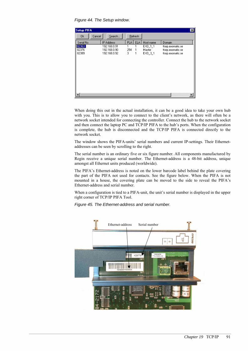
Chapter 19 TCP/IP 91
Figure 44. The Setup window.
When doing this out in the actual installation, it can be a good idea to take your own hub with you. This is to allow you to connect to the client’s network, as there will often be a network socket intended for connecting the controller. Connect the hub to the network socket and then connect the laptop PC and TCP/IP PIFA to the hub’s ports. When the configuration is complete, the hub is disconnected and the TCP/IP PIFA is connected directly to the network socket.
The window shows the PIFA-units’ serial numbers and current IP-settings. Their Ethernet-addresses can be seen by scrolling to the right.
The serial number is an ordinary five or six figure number. All components manufactured by Regin receive a unique serial number. The Ethernet-address is a 48-bit address, unique amongst all Ethernet units produced (worldwide).
The PIFA’s Ethernet-address is noted on the lower barcode label behind the plate covering the part of the PIFA not used for contacts. See the figure below. When the PIFA is not mounted in a house, the covering plate can be moved to the side to reveal the PIFA’s Ethernet-address and serial number.
When a configuration is tied to a PIFA-unit, the unit’s serial number is displayed in the upper right corner of TCP/IP PIFA Tool.
Figure 45. The Ethernet-address and serial number.
Ethernet-address Serial number

92 Part III EXOflex Software
Select the correct PIFA and click Ok. The parameters on the Local IP Settings tab are then loaded to the PIFA. The PIFA’s serial number is also saved in the unit’s configuration, which the tool saves to the hard drive. The serial number is then used by the tool when loading configurations etc.
If the TCP/IP PIFA unit is to be used as a slave and only uses the default configuration under the tab “Slave Configuration”, you only need to do “Setup PIFA” on the PIFA unit.
If a TCP/IP PIFA is moved to another controller, or if the IP-address is changed etc, Setup must be run again. You will then see the previous TCP/IP-settings in the window. In this case the PIFA setup can even be done from another network (via routers). Press the Search button in the setup window and specify the current IP-address. If the tool finds the PIFA it will be shown in the list.
Setup can also be done from another sub-net, if the PIFA already has an IP-address loaded. Click the Search button and enter its current IP-address and it will appear in the list.
Load the Configuration When the PIFA has been set up, the configuration can be loaded to it with the command Load Configuration in TCP/IP Tool. The tool uses the (saved) serial number from when Setup was used to identify the PIFA.
The configuration can be loaded from any network that can contact the PIFA via routers, but only as long as the IP-address has not been changed. If it has changed, Setup will need to be done again.
You might want to configure your PIFA-units before going to the customer’s installation. Usually, the customer uses other series of IP-addresses than the ones used for your own office. In order to solve this problem, you can change network configuration in the computer running TCP/IP PIFA Tool to one similar to the one that the PIFA-unit will have in the installation. The IP-address, which is selected in the same sub-net as the PIFA-unit, should be different than the PIFA-unit’s configuration. Depending on the network services installed in the computer, and their configuration, it might happen that the configuration still cannot be loaded to the PIFA-unit. The reason may then be settings in proxy-clients, dialed-up networks etc.
In order to make it possible to perform Load Configuration on a TCP/IP PIFA the computer that loads the configuration and the TCP/IP PIFA unit must be correctly configured for the network they are connected to. This means that an installer’s portable computer probably is not correctly configured for the client’s network. To be able to upload the configuration, the settings on the portable computer must be changed so they fit the client’s network. That Setup PIFA works does not mean that Load Configuration works. Setup PIFA is designed to work even if the network settings in the PIFA unit are erroneous.
Set the Processor’s Address If the controller is completely unconfigured ("cold-started"), it will have the address 254:30. The correct address must be set before the program can be loaded. This is normally done with the command Reset Controller in e.g. Project Builder.
This can however, be difficult to do via the TCP/IP PIFA-unit, as the routing table in the master is hardly likely to be configured for sending EXOline-messages with the address 254:30 to just that PIFA. You should therefore set the controller’s address locally, by connecting the computer directly to one of its serial ports.
It is however, still possible to cool start a controller via TCP/IP-PIFA-units, with no problems.

Chapter 19 TCP/IP 93
Loading the Operating System You can load the TCP/IP PIFA’s operating system with TCP/IP PIFA Tool. This is done with the command Load PIFAos. The command first displays a message showing the revisions of both the current operating system and the one about to be loaded.
For this to work, you must first have run setup on the PIFA. The tool uses the (saved) serial number from when Setup was used to identify the PIFA. Any configuration for the PIFA will be preserved when reloading the operating system.
The operating system can be loaded from any network that can contact the PIFA via routers, but only as long as the IP-address has not been changed. If it has changed, Setup will need to be done again.
From and including version 1.0-1-03 of EP8280-PIFAos, the PIFA-units’ error handling has been redesigned to also manage upgrades under difficult network conditions.
If the operating system in the PIFA-unit is older than version 1.0-1-03, we recommend you to do the upgrade in an ”isolated network”, where only the PIFA-unit and the computer loading the configuration are connected. This mainly applies to networks with a high load where the built-in error handling can restart the PIFA-unit during upgrade at network load peaks.
If TCP/IP PIFA Tool would report that the upgrade failed, it is important not to break the current to the PIFA-unit but to retry to carry through the upgrade. TCP/IP PIFA Tool will retry automatically, but will give up after three attempts.
If the PIFA-unit would be restarted or without current during upgrade, the PIFA-unit will stop functioning and has to be sent to Regin for reprogramming.
Advanced Applications
Multidrop
The TCP/IP PIFA supports multidrop on the main processor’s port 2 internally in an EXOflex-housing. Consequently, the PIFA-unit can be connected to the main processor’s port 2 with slave processors in the same house.
Figure 46. Multidrop on the main processor’s port 2.
”Master”CPU
”Slave”CPU 3
”Slave”CPU 2
”Slave”CPU 1
EP8280 EPxxxx EPxxxx EPxxxx
EP1011 EPxxxx EPxxxx EPxxxx
P2
P2
P1 P1 P1
For this type of configuration, it is important that the slave processors’ piping settings are made in such a way that they do not overlap the PLA- and ELA-ranges defined in the PIFA-unit’s routing table. The TCP/IP PIFA uses its routing table correspondingly to how the EXOreal-processor uses the variables Max_ELA, Max_PLA, Min_ELA and Min_PLA.

94 Part III EXOflex Software
The TCP/IP PIFA can also be used for multidrop applications with port 2 on the main processor and other communication units. With the TCP/IP PIFA is is possible to manually, using the configuration tool, choose which port the PIFA should connect to.
The configuration of a system where the communication PIFA is used in a multidrop application together with the TCP/IP PIFA is done in the following way: The communication PIFA unit is configured as usual by choosing Connect to PIFA in Controller System Tool. In the configuration of the TCP/IP PIFA, the setting To port #2 of the main processor on the tab Port Connection is chosen.
The same configuration can also be done with two TCP/IP PIFA units instead of a communication PIFA and a TCP/IP PIFA. It is important that the posts in the routing table of the TCP/IP PIFA are not overlapping the routing range that has been configured in controllers connecting to the main processor’s port 2.
The same multidrop functionality can be used by the PIFA-unit in TCP/IP Gateway version, se TCP/IP Gateway, page 129.
TCP/IP PIFA units with serial numbers lower than A0070240 do not support connection to the main processor’s port 2 and can therefore not be used for multidrop applications in an EXOflex housing. The support for the main processor’s port 2 in these PIFA units is missing in the hardware. PIFA units without previous support for multidrop on EXOline when the PIFA is included in a TCP/IP Gateway can, however, be made to support multidrop on EXOline by a software upgrade to EP8280 PIFAos version 1.0-1-00 or later.
Multimaster The multimaster function opens new communication possibilities in the EXO system. For example can a separate controller be connected that handles varible transfers between the controllers in parallel with the rest of the communication. However, this requires an extra TCP/IP PIFA and a CPU in the communications unit, but will, especially in large systems, increase the communication speed between EXO4 and the controllers.
TCP/IP PIFA units that are used as slaves can handle tha communication with several master controllers at the same time. If two station masters simultaneously each send a question to the station slave, one of the controllers answers will be slightly delayed, while the message from the other station master is being processed. This means that the number of messages per second from one of the masters will be somewhat lower than had it been alone. The total number of messages per second will however increase since the slave recieves the next message from the queue as soon as it has processed the previous message.
Firewalls
To communicate via TCP/IP PIFA-units through a firewall, it must be configured for that purpose. A firewall is a unit that only allows TCP/IP-communication on certain port numbers and not on others. TCP/IP-ports work as separate communication channels between two nodes. The TCP/IP PIFA-units use separate ports for operation and configuration, as described below:
Type of Communication Port number Protocol
Normal operational traffic. 26486 TCP Configuration, i.e. the commands Setup PIFA, Load Configuration and Load PIFAos.
26487 TCP, UDP

Chapter 19 TCP/IP 95
Hardware Interface The TCP/IP PIFA has two connections to the outside world. The first is an RJ-45 contact for connecting to Ethernet via a TP-cable (10base-T). The other is a two-pole Phoenix-plinth for connection to protective earth, which is necessary for the function of the equipment’s lightning protection.
See also Error! Reference source not found. on page Error! Bookmark not defined..

96 Part III EXOflex Software
Chapter 20 Applications
Controller Objects When using an EXOflex-controller, you first add the PIFA-units with EXOflex I/O Tool and then use PIFA I/O Tool to configure names and properties for your resources (inputs and outputs). If you want to e.g. connect an analog input to an outside temperature sensor, give that analog input the name Outtemp in PIFA I/O and configure the sensor type, filtering factor etc. In your object, you then connect the variable Outtemp directly to e.g. a regulator object. This procedure is the same for other inputs and outputs.
This means that you do not have to use special input and output objects when programming EXOflex-controllers, thus reducing the number of objects in a controller.
It will be easier to re-use ready configured objects if you use a standard form for your resource names. You might have e.g. configured sets of objects for different types of ventilation aggregates. All you would then have to do would be to configure your inputs and outputs in PIFA I/O.
Display The external display in the EXOflex-system has more keys than non-EXOflex-controllers. Normally you do not program the display handling directly, but instead use the ready-made controller functions in EXOdesigner.
For this to work, you must use new versions of the affected controller functions. EXOflex requires the following versions:
Dialog 3.3
Station Handle Program 3.3
Time Dialog Program 2.0
For configuration purposes, the new versions are identical to their predecessors. It is only the user interface seen in run time that has been changed.
The new versions of the controller function are general, and can well be used even in non-EXOflex-controllers.
Display In normal move-mode, things work much the same as before, but with the new keys.
The greatest difference is in how maneuvers are performed. Earlier, there were two different maneuver-modes: input-mode and increase/decrease-mode. These have now been merged into one general change-mode, with the following advantages.
The entering of numerical values is now much freer, i.e. you can enter any amount of digits and place the decimal point where you like. You can also choose whether to edit the existing value [↵] or enter a completely new one [C]. When entering a value, you can delete characters one by one if you make a mistake [C] and you can move around freely with the arrow keys. The entry process can be cancelled at any time by a long [C].

Chapter 20 Applications 97
As before, you can step the value up [+] or down [-]. Earlier, you always had to step the final digit in the value, but now you step the digit at the cursor, which can be freely moved back and forth with the arrow keys.
Station Handler Station Handler handles the display of alarms on the external display.
You move around, as before, with the keys [↑], [↓], [←]. To acknowledge press [↵], to block/unblock press [C].
It is also now possible to use alarm texts of more than 20 characters. The text can be scrolled with the key [→].
Time Schedules Display Time Schedules Display handles the larger keypad in the same way as Display during maneuvers. Furthermore, the program uses a completely new structure for the dialog boxes. This new structure should be easier to learn and more like Display’s structure. This version can also be used in non EXOflex-controllers, with the new structure.
See the example below.
TimeGroup01
--> Mon: TimeChannel01
TimeChannel01
Per 1: 08:00-16:00
TimeGroup01
TimeGroup01
Tue: TimeChannel01
TimeGroup01
Hol: TimeChannel04
TimeChannel01
Per 2: 21:00-23:00
TimeChannel01
Per 3: 00:00-00:00
TimeChannel01
Per 4: 00:00-00:00
TimeGroup02
-->
TimeGroup01
Wed: TimeChannel01
TimeGroup01
Thu: TimeChannel01
TimeGroup01
Fri: TimeChannel01
TimeGroup01
Sat: TimeChannel04
TimeGroup01
Son: TimeChannel04
TimeGroup03
-->
Holidays
--> Per 1: 01.01-01.01
Holidays (MM.DD)
Per 2: 01.05-01.05
Holidays (MM.DD)
Per 3: 12.24-12.26
Holidays (MM.DD)

98 Part III EXOflex Software
Limitations
Performance EXOflex-controllers have exactly the same performance as all other EXO controllers with the 22 MHz processor. It is true that EXOreal itself does not need to handle the hardware resources directly, but only indirectly via the EFX-channel. The handling of the EFX-channel however, puts about the same load on the controller as hardware resources in e.g. the model 5540.
The free processor capacity available for application programs is therefore approximately the same in an EXOflex-controller as in model 5540. The PIFA-units however, contain many functions that need to be done in the application programs in other models. In applications where the PIFA-units’ extra functions are required, you will thus have more processor capacity available to the rest of the application.
Furthermore, EXOreal 2.8 has somewhat better performance than earlier versions when handling long VPacs and BPacs. This improvement applies to all models.
Memory EXOflex controllers have 512 kByte of expanded memory, of which 480 kB can be used to its limits.
The general limits (for all models) are otherwise:
Tasks: Maximum 15, consisting of 256 segments each.
DPacs: Maximum 62, consisting of 256 segments each.
Texts: Max 240 (possibly fewer if the texts are very long).
The number of DPacs is enough for all normal applications, even if you put a great many functions in a controller.
The limitations on the Tasks are probably not a problem either. The greatest likelihood of running into problems is when programming controllers with Controller Objects and using large numbers of functions. One (unsatisfactory) solution might be to spread the functions over more Tasks.
Texts The most important limitation is the one for Texts. The maximum of 240 texts must be shared by a number of different controller functions. See below:
Station controllers
In station controllers it is normally the following programs that will be working together.
Alarms and Events, needs a text for each alarm point. If the alarm will only be shown in EXO4, you can do without text in the controller.
Station Handler, needs 10 texts.
Time Schedules Display, needs 3 texts, plus a text for each time object.
Display, needs 4 texts plus a text for each alternative in dialog boxes using text swapping functions. The static texts can be placed in BPacs (Large Storage).
Central controllers
In central controllers the following programs will normally be present.
CCP, needs 11 texts plus one text per modem-dialed station (for telephone numbers).

Chapter 20 Applications 99
Alarms and Events, with one text for each station using alarms for unreachable stations. If the alarm is only shown in EXO4, you can do without texts in the controller.
Pager/SMS, needs 43 texts, plus one text per station (i.e. the stations’ name in plain text)
Log Channels The number of log channels is limited to 96 per controller. There are no plans for increasing this amount in the foreseeable future.
Alarm Points The number of alarm points is limited to 250 per controller. If you need alarm texts in the controller, the limit will be even lower. See Texts above.
This will not be increased in the foreseeable future
Multi-processor Houses If, in a processor house, you get problems with one of the limitations mentioned above, your first thought might be to install some more processors. This, however, cannot be done all that easily, as programs you will be using cannot interact between controllers as might be desired.
Houses with several processors are, as far as software is concerned, exactly the same as several separate controllers.

100 Part IV Specifications
PPaarrtt IIVV SSppeecciiffiiccaattiioonnss

Chapter 20 Applications 101
Table of contents Part IV Specifications
Enclosure Specifications 102 Houses 102 External Display 102 Dimensions 102 Section Widths 103
Environment Specifications 104
Processor Specifications, ECX1 105 Specifications 105
General PIFA Specifications 106 What is there to choose from? 106 PIFA-positions 106 Common Properties for PIFA-units 107
Communication Ports 107 Standard 24 V DC DI 109 Electrical Specifications 109 Standard 24 V DC DO 110 Electrical Specifications 110 Multisensor AI 111 Standard AO 111

102 Part IV Specifications Enclosure Specifications – datasheet: A
Enclosure Specifications
Houses An EXOflex house can be divided into its aluminum and plastic components.
Plastic Components The plastic components are of injection-molded, flame-resistant ABS plastic. The flame resistance is to class V0, which means that the plastic will self-extinguish in the case of fire.
Aluminum Components The aluminum components are of extrusion-pressed anodized aluminum. The anodization has good resistance to light and chemicals.
Sealing The casing sealing is to class IP30, i.e. it is intended for cabinet mounting
External Display Refer to the external display specifications.
Dimensions Figure 47. A side-view of the EXOflex house, with dimensions.
125mm115mm
160mm

Enclosure Specifications – datasheet: A Enclosure Specifications 103
Section Widths Figure 48. Section widths
Section width 1 = 117 mm
Section width 2 = 229 mm
Section width 3 = 341 mm
Section width 4 = 453 mm
EH1x
EH2x
EH3x
EH4x

104 Part IV Specifications Environment Specifications – datasheet: B
Environment Specifications
EXOflex-units may be used under the following conditions: Operating temperature .............................................................................................. 0 to +50oC Storage temperature............................................................................................... -20 to +70oC Humidity (non-condensing)........................................................................................max 95 % Above sea level.......................................................................................................max 2000 m

Processor Specifications, ECX1 Processor Specifications – Datasheet A 105
Processor Specifications, ECX1
The processor function is built on two circuit boards, one of which contains an EXOreal processor and the other an EFX processor. The EXOreal processor handles EXOL application code and external serial communication via Port 1-3. The EFX processor is responsible for the exchange of data between the EXOreal processor and PIFA-units via the EFX channel. Port 1 has its physical output on the EPU’s power-PIFA, whilst Ports 2-3 have theirs on special communication PIFA-units, the type EP8102. The EFX-processor is responsible for the exchange of data between the EXOreal-processor and PIFA-units via the EFX-channel. The EFX-channel has built-in error handling with a CRC-16 check sum.
Specifications CPU-board Operating system..........................................................................................................EXOreal CPU.................................................................................................................................C515C ROM-memory with EXOreal operating system............................................................... 64 kB Conventional RAM memory ............................................................................................ 32 kB Expanded RAM memory ............................................. 512 kB (480 kB can currently be used) Battery backup of RAM, RTC ......................................... 5 years with one processor installed Battery monitoring .......................................................................... LED + software accessible EEPROM with factory settings .......................................................................................... 2 kB Real-time clock (RTC) ..................................................................................... ±30 sec./month. Port 1 ...............................................................................................RxD, TxD, RTS (E-signal) Port 2 .......................................................................................................RxD, TxD, RTS, CTS Port 3 ................................................................... RxD, TxD, RTS, CTS, RI, DCD, DTR, CTS
The battery is located on the power PIFA. A backup capacitor on the CPU board retains the contents of the memory for at least 30 minutes when the unit is not powered.
EFX-board Operating system.............................................................................................................EFXos CPU.................................................................................................................................C515C EFX-channel .................................................................................................RS485/115200bps ROM-memory with EFX operating system ..................................................................... 64 kB Dual port RAM .................................................................................................................. 2 kB Internal Power Consumption CPU + EFX 5 V................................................................................................................................. 100 mA

106 Part IV Specifications General PIFA Specifications – Datasheet: E
General PIFA Specifications
This chapter provides a general overview of the PIFA-units currently available.
What is there to choose from? The following overview is a list of PIFA-units. Detailed descriptions can be found in product sheets, which are available from our web site http://www.regin.se.. Other units may exist. Please contact your nearest supplier or AB Regin for information on the current range.
Model Number Description
EP1004 Power PIFA for extender EP1011 Main Power PIFA EP2032 32 DI Multifunction PIFA EP3016 16 DO Multifunction PIFA EP4024 16 DI / 8 DO mixed Multifunction PIFA EP5012 12 AI Multisensor PIFA EP5112 12 AI Multisensor PIFA EP6012 12 AO Voltage Multifunction PIFA EP7218 12 AI / 6 AO mixed Multifunction PIFA EP7408 8 Mixed I/O PIFA EP7416 16 Mixed I/O PIFA EP7601/EX7601 Access Control PIFA/Unit EP8101 Basic Serial PIFA EP8102 Dual Basic Serial PIFA EP8210 EXOlon PIFA EP8280 TCP/IP PIFA (replaced by EP8282) EP8282 TCP/IP PIFA ED9200 External Display Modem 9011 PTT Modem (Option 9011) Model 9035 Battery Charger/UPS (Option 9035) EP0000 Blind PIFA
PIFA-positions PIFA-units can generally be mounted in any of the compartments in an EXOflex house, although there are certain exceptions. A power PIFA must always be present and must always be mounted in position 1. The same position designation is used even when the house is mounted vertically, which makes it possible to refer to e.g. position 1 with no risk of being misunderstood. See also Chapter 9 Commissioning for more information about positions.
General PIFA Specifications – Datasheet: E General PIFA Specifications 107
Common Properties for PIFA-units The power supply to the parts of the PIFA closest to the process is always external,
although there are certain exceptions, e.g. the TCP/IP PIFA.
The process connections on an individual PIFA-unit are, viewed as a group, galvanically isolated from the internal control logic circuits by a special protective barrier, which is bridged by an opto-coupler, relays etc. The isolation from other circuits can be retained by using a separate power supply.
Each process connection has active transient protection, which is led to a special EMI earth (disturbance protection earth) or in some cases to protective earth.
Calibration parameters for analog inputs etc, are stored in the PIFA-units’ EEPROM, which is not dependent on a power supply. PIFA-units can thus easily be replaced.
Connections are usually made on plug-in screw connectors of the Phönix brand, although there are exceptions for certain communication ports.
Communication Ports See the specifications for each respective PIFA for more information about that particular model.
Ports 1, 2 and 3 All standard ports, ports 1, 2 and 3 have selectable physical interfaces in the form of
EXOline, hlEXOline or RS232 as standard. See also Chapter 13 Communication.
Port 3 has a full set of control signal for RS232 and advanced modem support, whilst the other ports have a limited set, as described below. Port 3 can also be fitted with an option card, which further increases the freedom of choice for this interface. See also Chapter 27 Options.
hlEXOline is obtained by changing a jumper setting on the power-PIFA.
The RS232 interface is selected via the hardware if you connect the signal SEL1, 2, 3 to GND1, GND2, GND3 for the respective port.
Electrical Specifications Type ........................................................................... EXOline (RS485), hlEXOline or RS232 standard .....................................................................................................................EXOline Speed...........................................................................................configurable, max 19200 bps, standard .................................................................................................................... 9600 bps Galvanic isolation from the rest of the electronics, common mode voltage............. max 250 V
Port 1 Control signals, RS232............................................................................... RxD, TxD and RTS Control signals, RS485............................................................................................................ E Connector EXOline and hlEXOline ...................................................................Terminal block Connector RS232 ...............................................................................................................RJ45
Port 2 Control signals, RS232......................................................................RxD, TxD, RTS and CTS Control signals, RS485............................................................................................................ E Connector EXOline, hlEXOline and RS232 ......................................................Terminal block

108 Part IV Specifications General PIFA Specifications – Datasheet: E
Port 3 Control signals, RS232..................................RxD, TxD, RTS, CTS, DTR, DSR, RI and DCD Control signals, RS485............................................................................................................ E Connector EXOline, hlEXOline and RS232...................................................... Terminal block
EFX channel (internal) Type.................................................................................................................................RS485 Communication speed ............................................................................................. 115200 bps

General PIFA Specifications – Datasheet: E General PIFA Specifications 109
Standard 24 V DC DI Please see the specifications for each respective PIFA for more information about that particular model.
Figure 49. Block diagram for a standard digital input.
PIFA
LimR
24V DCexternal supply
+C
+C
EMI return(earth)
uP
EFX-channel
EMIborder
Properties This type of input is used for reading off floating (potential free) contacts and are active
high.
A yellow LED for each input shows its current status.
The EFX channel is used to connect the PIFA-unit to the processor (not applicable for EP1011).
Process Connections The external contact’s one end is connected to the input and the other to +C. The +C
output is current limited and short circuit proof.
EMI earth must be connected to the earth rail or equivalent, to prevent disturbances.
The power supply’s 0V connection must also be grounded. This is normally done at the power unit’s 0V output.
Electrical Specifications Digital Inputs, Type DC Logic 0 .......................................................................................................................... 0 to 5 V input current at 0 V.......................................................................................................... 0 mA input resistance......................................................................................................... 5,7 kOhm Logic 1 ...................................................................................................................... 11 to 30 V input current at +24 V ..................................................................................................... 4 mA Shortest pulse length for detection, software type normal.... 9ms (not applicable for EP1011) Shortest pulse length for detection, software type advanced4,5ms (not applicable for EP1011)

110 Part IV Specifications General PIFA Specifications – Datasheet: E
Standard 24 V DC DO Please see the specifications for each respective PIFA for more information about that particular model.
Figure 50. Block diagram for a standard digital output.
PIFA 24V DCexternal supply
–C
EMI return(earth)
uP
EFX-channel
EMIborder
Load
Load
–C
Lim
Properties This type of current source output is mainly constructed for use with DC-relays, lamps
and the like.
The outputs’ driving stage is powered from the external supply
Each output is current limited, short circuit protected and has overheat protection. Apart from the current limiting for each individual output, there is also total limiting for all of the outputs together. See Lim in the illustration above.
A yellow LED for each output shows its status.
Process Connections An external load is connected between the output and -C.
The EMI earth must be connected to the earth rail or equivalent, to protect against disturbances.
The 0V connection must also be grounded. This is normally done at the power unit’s negative pole.
Electrical Specifications Digital Outputs, Type DC Type..................................................................................................................... current source Current is fed from the PIFA-unit’s power supply connection Output voltage at logical zero............................................................................ max 2 V/12 uA Output current at +24 V (source) max continuous load per output............................................................................min 400 mA max continuous load per output at max. 30°C run temp ......................................min 500 mA max transient load (20 ms) ..........................................................................................min 1 A

General PIFA Specifications – Datasheet: E General PIFA Specifications 111
Multisensor AI See the specifications for each respective PIFA for more information about that particular model.
Properties This type of input is mainly intended for use with sensors using voltage outputs and
resistance elements for measuring temperature, pressure, flow, etc. Certain models also have a 0-20 mA input.
Process Connections Voltage signals are connected between the input and Agnd.
The cable screen is connected to the connector SCR.
The EMI earth must be connected to the earth rail or equivalent, to prevent disturbances.
The 0V connection must also be grounded. This is normally done at the power unit’s negative pole.
The +C output is always current limited. External transmitters for 4-20mA can be powered from a +C output. A fast fuse should be fitted in serial with the transmitter to protect the input from short circuits in the transmitter.
For PIFA-models in the range 0–20 mA, the current shunt resistor is activated by software-controlled electronic circuits. The shunt resistor has an active current limiter that limits the current to approximately 25mA. However, the input voltage must not exceed 12V on the input, as each input also has active transient protection that activates at this voltage level.
All analog inputs have active transient protection that activates at an in-voltage of >12 V. This means that if you mistakenly allow 24 V on an input for longer than approx. 0.5 seconds the input will be permanently damaged and the guarantee will not be valid!
If you connect an active transmitter (4–20 mA) and power it with 12 V, the analog input will not be damaged if the transmitter is mistakenly short-circuited.
Standard AO See the specifications for each particular PIFA for more information about that particular model.
Properties Each output is current limited and short circuit proof.
This type of output is mainly intended for use with damper motors, shunt valves, frequency inverters and other analog actuators for 0–10 V.
Process Connections Normal, high-ohm loads are connected between the output and AGnd. Other types of
loads for special applications with low-ohm loads are best connected between the output and 24Vminus.

112 Part IV Specifications General PIFA Specifications – Datasheet: E
The EMI earth must be connected to the earth rail or equivalent, to prevent disturbances.
The 0V connection must also be earthed. This is normally done at the power unit’s negative pole.
Cable screens can be connected to the connector SCR (if present).

EP9011 Specifications – Datasheet: B Model Modem 9011 - PTT Modem 113
Model Modem 9011 - PTT Modem
Introduction Modem 9011 has the following main functions:
V.22bis/V.22/V.21 and BELL 212A/103 compatible design with automatic detection of data communication standard.
Operate in character asynchronous mode.
Includes an advanced "AT" command interpreter compatible with 2400 bit/s industry standard products.
Includes non-volatile memory to store user configurations.
Adaptive equalization for optimum performance over all lines.
Dynamic range from -3 to -45 dBm.
Call progress, carrier and answer tone detectors providing intelligent dialing functions.
Built-in speaker for easier error detection.
DTMF and CCITT guard tone generators.
High reliability in real life operation.
CE-marked according to the European R&TTE Directive for use in Belgium, Denmark, Finland, France, Germany, Holland, Norway, Sweden and the U.K.
Modem 9011 is a high performance, 2400 bit/s intelligent modem for use in dial-up telephone network applications in EXO installations. It is 100 % compatible with the EXOmodem 9010, with one exception: The 9011 modem does not include the capability to make pulse dialing.
It includes a complete "AT" command and feature set compatible with industry standard products. Its operating modes are compatible with CCITT V.22bis, V.22 and V.21 as well as BELL 212A and 103 data communication standards. The modem may only be used in EXO Processor controllers (see price-list).
The 9011 modem has been designed for high reliability in real life operation surrounded by noise, interfering equipment and sometimes even thunderstorms generating high voltages and transients. This has been accomplished by a careful component selection and by good layout practice. Critical components in the line interface are chosen to withstand 4kV isolation voltage between the line and the internal logic. Surge arrestors and a gas discharge tube positioned on the motherboard close to the line inlet takes care of both fast transients and high voltages with a high energy content.
114 Part IV Specifications EP9011 Specifications – Datasheet: B
Specifications Power Supply Internal
Internal Power Consumption 5 V .................................................................................................................................140 mA 12 V .................................................................................................................................10 mA -12 V................................................................................................................................10 mA
Other Parameters Modulation ............................................ CCITT V.22bis, V.22, and V.21 Bell 212A and 103, Dial-up...................................................................................................... Tone signals, DTMF Transmission .......................................................................................................Asynchronous Insulation between line and internal circuits ......................................................................4 kV Settings ............................................................................................................... AT commands Line.................................................................................................................. two-wire dial-up Line Interface..................................................................................... plug-in screw connector transmit level .............................................................................................................-13 dBm impedance.................................................................................................................600 Ohm reception level ............................................................................................ down to –43 dBm Standard..........................................................................................................................TBR21

EP9011 Specifications – Datasheet: B Model Modem 9011 - PTT Modem 115
Function Models 3397, 5540 and the EXOflex series etc. have an internal slot for optional functions like the Modem 9011 card. The modem is controlled from the EXOreal Processor and its Port 3.
In EXOflex the modem is normally positioned in the lower Option position in section 1 together with a Basic or Dual Basic Serial PIFA like EP8101 or EP8102 and a Processor. Also the lower Option positions in section 2, 3 or 4 may be used. This requires an additional Processor and a Serial PIFA per modem in each section.
When commanded from an EXO Processor controller the modem will automatically perform a complete handshake as defined by the V.22bis, V.22, V21 or BELL 212A/103 standards to connect with a remote modem.
The modem includes an "AT" command interpreter which is compatible with the Hayes 2400 Smartmodem command set. Also see section Hayes Commands.
The modem includes internal non-volatile memory to store the current "AT" command configuration etc.
Settings of Speed and Format
Settings for speed and format are carried out automatically. The modem corrects itself for speed, number of data bits and parity each time an AT command is sent.
In transparent mode (data mode) the modem handles a total of 9, 10 or 11 bits as shown below: S1--D1--D2--D3--D4--D5--D6--D7--S2 7 data bits without Parity
S1--D1--D2--D3--D4--D5--D6--D7--PB--S2 7 data bits with Parity
S1--D1--D2--D3--D4--D5--D6--D7--D8--S2 8 data bits without Parity
S1--D1--D2--D3--D4--D5--D6--D7--D8--PB--S2 8 data bits with Parity
In command mode result codes, if activated, will be shown in the following format:
S1--D1--D2--D3--D4--D5--D6--D7--D8--S2 8 data bits without Parity.
Note: S1 = start bit
D1-D8 = data bits
PB = parity bit
S2 = stop bit
Parity can be EVEN, ODD, MARK or SPACE.

116 Part IV Specifications EP9011 Specifications – Datasheet: B
Hardware Preparations and Installation Normally no preparations are necessary, but the following steps may be considered
For how to install and remove the modem, see Chapter 25 Installing Processors and Option Cards.
If no speaker function is desired, disconnect jumper J4. See Figure 51 below.
Figure 51. Modem 9011 with cut-off edges
Indicator led´s
Jumper J4
Four pole connector
Jumper J4 Description
Jumper off Speaker is electrically disconnected Jumper on Speaker is electrically connected
1 = Connected jumper
Insert the Modem 9011 PCB in the Option slot
Observe that Modem 9011 with cut-off edges only fits into EXOflex. For other models, e.g. 5540, the cut-off edges must be cut before mounting.

EP9011 Specifications – Datasheet: B Model Modem 9011 - PTT Modem 117
Connections and Wiring Connect the incoming telephone line to terminal R (Ring) and T (Tip) on the controller. If for any reason the modem does not react to ring signals, outputs A and A1 can further connect the telephone line to a telephone etc, if desired. Connector marked with earth symbol ( ) must be connected to a nearby ground bar or similar with a heavy wire in order to bypass transients.
The table below also shows which pins to connect to in a standard 6 pole RJ12 plug.
Modem 9011 Connector
Function Connect to: RJ12 plug UK
R Ring Analog PSTN 3 (or 4) 2 (or 5) T Tip Analog PSTN 4 (or 3) 5 (or 2) A Secondary Ring Phone A1 Secondary Tip Phone Transient ground Ground bar
The Modem 9011 connector symbols, R, T, A and A1, correspond to the ones on the serial ports on e.g. EP8101 and EP8102.
EXOreal and Modem 9011 With EXOapt 2001 or later and Controller System Tool (in EXOdesigner) you can easily configure whether Port 3 shall be connected to the internal or to the external Port 3 connector.
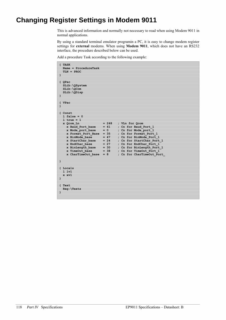
118 Part IV Specifications EP9011 Specifications – Datasheet: B
Changing Register Settings in Modem 9011 This is advanced information and normally not necessary to read when using Modem 9011 in normal applications.
By using a standard terminal emulator programin a PC, it is easy to change modem register settings for external modems. When using Modem 9011, which does not have an RS232 interface, the procedure described below can be used.
Add a procedure Task according to the following example:
TASK Name = ProcedureTask TLN = PROC QPac SLib:\QSystem SLib:\QCom SLib:\QDisp VPac Const l false = 0 l true = 1 x Qcom_Ln = 248 ; VLn for Qcom x Baud_Port_base = 41 ; Cn for Baud_Port_1 x Mode_port_base = 0 ; Cn for Mode_port_1 x Format_Port_Base = 35 ; Cn for Format_Port_1 x BinMode_base = 47 ; Cn for BinMode_Port_1 x StartChar_base = 24 ; Cn for StartChar_Port_1 x EndChar_base = 27 ; Cn for EndChar_Port_1 x BinLength_base = 30 ; Cn for BinLength_Port_1 x TimeOut_base = 38 ; Cn for TimeOut_Port_1 x CharTimeOut_base = 8 ; Cn for CharTimeOut_Port_ Locals l lv1 x xv1 Text Reg:\Texts

EP9011 Specifications – Datasheet: B Model Modem 9011 - PTT Modem 119
Code ;-------------------------------------------------------------------------- DEFSTAT BinaryInit x xv1 bit( Format_Port_3, 4 ) = 1 ; 8 data bits bit( Format_Port_3, 5 ) = 0 ; Parity off bit( Format_Port_3, 6 ) = 1 ; Parity ODD ; Set binary mode (Start at SOM and terminate after timeout) sxv( Qcom_Ln, BinMode_Base-1+xv1 ) = 0 ; Set start of message character... sxv( Qcom_Ln, StartChar_Base-1+xv1 ) = 13 ; Set binary message length... sxv( Qcom_Ln, BinLength_Base-1+xv1 ) = 100 ; Set the timeout... sxv( Qcom_Ln, TimeOut_base-1+xv1 ) = 20 ; x 64 ms siv( Qcom_Ln, CharTimeOut_base+(xv1-1)*2 ) = 100 ; x 4 ms ; Set port mode to MASTER... sxv( QCom_Ln, Mode_Port_Base+xv1-1 ) = 1 bit( Signal_Port_3, 0) = 1 ; Set DTR high Delay 11 ; Wait for a second ENDSTAT l lv1 ;-------------------------------------------------------------------------- DEFSTAT BinaryTerminate x xv1 bit( Format_Port_3, 4 ) = 1 ; 8 data bits bit( Format_Port_3, 5 ) = 1 ; Parity on bit( Format_Port_3, 6 ) = 1 ; Parity ODD ENDSTAT l lv1 ;-------------------------------------------------------------------------- DEFSTAT Speak2Modem $ Binary$ ; Add Linefeed to the command... $ Binary$ = Binary$ + CHR(13) $ Binary$ = InOut$( 3, Binary$ ) l lv1 = not cmp$( "" = Binary$ ) ENDSTAT $ Binary$, l lv1 ;--------------------------------------------------------------------------------
Now you have the procedures necessary to communicate to the modem.
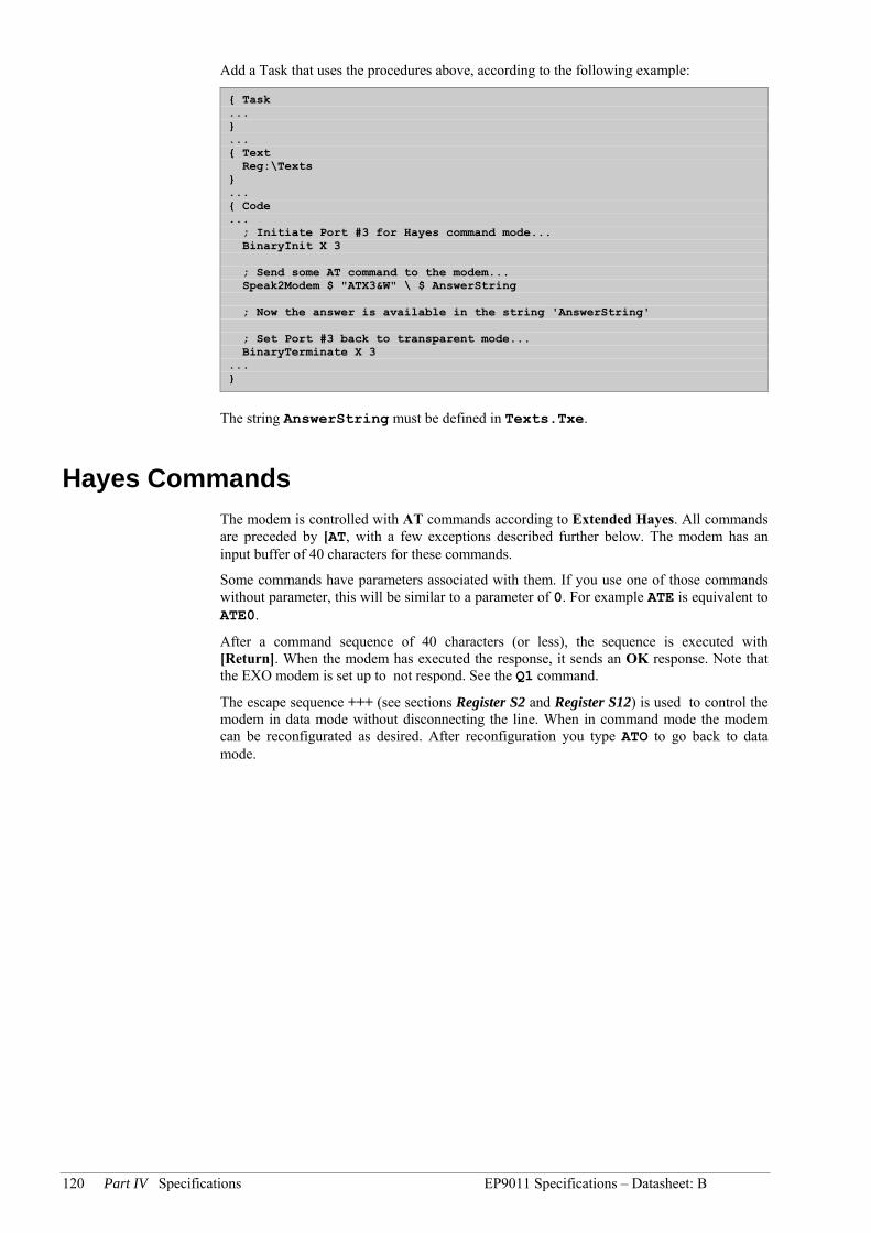
120 Part IV Specifications EP9011 Specifications – Datasheet: B
Add a Task that uses the procedures above, according to the following example:
Task ... ... Text Reg:\Texts ... Code ... ; Initiate Port #3 for Hayes command mode... BinaryInit X 3 ; Send some AT command to the modem... Speak2Modem $ "ATX3&W" \ $ AnswerString ; Now the answer is available in the string 'AnswerString' ; Set Port #3 back to transparent mode... BinaryTerminate X 3 ...
The string AnswerString must be defined in Texts.Txe.
Hayes Commands The modem is controlled with AT commands according to Extended Hayes. All commands are preceded by [AT, with a few exceptions described further below. The modem has an input buffer of 40 characters for these commands.
Some commands have parameters associated with them. If you use one of those commands without parameter, this will be similar to a parameter of 0. For example ATE is equivalent to ATE0.
After a command sequence of 40 characters (or less), the sequence is executed with [Return]. When the modem has executed the response, it sends an OK response. Note that the EXO modem is set up to not respond. See the Q1 command.
The escape sequence +++ (see sections Register S2 and Register S12) is used to control the modem in data mode without disconnecting the line. When in command mode the modem can be reconfigurated as desired. After reconfiguration you type ATO to go back to data mode.

EP9011 Specifications – Datasheet: B Model Modem 9011 - PTT Modem 121
AT Commands Supported Note: s = string
n = 0-255 decimal
x = Boolean
0/1 = false/true
Command Options Default
A/ Repeats last command line N/A
A Answer N/A
Bx BELL/CCITT=1/0 answer tone @ 1200 (N/A @ 2400) 0
DS=n Dial string specified by n, n = 0-3 n = 0
Ex Command echo, 0/1 = OFF/ON 0
Hn Hook status, 0/1 = ON/OFF N/A
Ln Speaker volume, (0)1/2/3 med/med/med, supports only one volume 2
Mn Speaker, 0/1/2/3 = control (see Table 8) 1
On Online, 0/1/2/3 = online/retrain/no retrain (see Table 9) N/A
P Not supported
Qx Quiet result, 0/1 1-quiet 1
R Reverse originate N/A
Sn=n Set S register (see Table 2) N/A
Sn=? Return value in register n (see Table 2) N/A
T Touch tone dial Pulse
Vx Verbose result, 0/1 = ON/OFF 1
Xn Result code, 0/1/2/3/4 (see Table 1) 4
Yx Enable long space disconnect, 1 = enable 0
Zx Restore from Non-Volatile Memory, x = 0 or 1 N/A
&Cx Carrier detect override, 0/1 = ALWAYS ON/NORMAL 1
&Dn DTR Mode, 0/1/2/3 (see Table 10) 3
&F Restore to factory configuration N/A
&Gn CCITT guard tone, 0/1/2 = OFF/1800/550 2
&J Auxiliary relay control, may not be changed! 1
&Mn Async only, (see Table 11) 0
&Qx Same as &M 0
&Rx Enable RTS/CTS 0
&Sx DSR override, 0/1 = US/UK 0
&V View active configuration and user files N/A
&Wx Write current configuration to NVRAM x = 0 or 1 0
&Yx Designate default user profile Z0 or Z1 N/A
&Zn=s Store a telephone number n = 0-3 N/A
Factory Configuration
B0 E0 L2 M1 P Q1 V1 X4 Y0 &C1 &D3 &G2 &J1 &M0 &P0 &R0 &S0 &T5 &X0
If the NOVRAM has not been initialized it may be necessary to Power Down/Power Up and type AT&F&W<cr> to properly initialize modem state.

122 Part IV Specifications EP9011 Specifications – Datasheet: B
Dial String Arguments
, Delay 2 sec
; Return to Command
@ Silent Answer during 5 sec during a period of S/sec
s Dial Stored Number
! Flash, Corresponds to the R button in most countries, Breaks the line in 90 ms
W Wait for Tone
R Reverse Mode
Please Observe So-called blind dialing, using the comma (,) character instead of the wait (W) character in the dial string, is not allowed.
Table 1: Result Codes
Xn Vocal/Numeric Result Code
X0 OK/0, CONNECT/1, RING/2, NO CARRIER/3, ERROR/4 X1 All functions of X0 + CONNECT (RATE)/1 = 300, 5 = 1200, 10 = 2400 X2 All functions of X1 + NO DIAL TONE /6 X3 All functions of X1 + BUSY/7 X4 All functions of X3 + NO DIAL TONE /6
Table 2: S Registers Supported
Sn Function Units Default
S02 Answer on ring No of rings 000 S1 Ring counter No of rings up to 8 000 S2 Escape code ASCII CHR$() 043 S3 Carriage return ASCII CHR$() 013 S4 Line feed ASCII CHR$() 010 S5 Backspace ASCII CHR$() 008 S6 Wait for dial tone Seconds 002 S7 Wait for carrier Seconds 030 S8 Pause time Seconds 002 S9 Carrier valid 100 milliseconds 006 S10 Carrier drop out 100 milliseconds 014 S11 DTMF tone duration 1 millisecond 070 S12 Escape guard time 20 milliseconds 050 S13 Unused N/A *S142 Bitmapped register Decimal 0-255, See Table 3 140 S15 Unused N/A S16 Test register Decimal # 000 S18 Test timer Decimal 0-255 000 S19 Unused N/A S20 Unused N/A *S212 Bitmapped register Decimal 0-255 See Table 4 057 *S222 Bitmapped register Decimal 0-255, See Table 5 118 *S232 Bitmapped register Decimal 0-255, See Table 6 166

EP9011 Specifications – Datasheet: B Model Modem 9011 - PTT Modem 123
S24 Unused N/A S252 DTR delay 10 milliseconds 005 S262 CTS delay 10 milliseconds 001 *S272 Bitmapped register Decimal 0-255, See Table 7 000
* The bitmapped register functions are equivalent to normal "AT" command modem registers. 2 Stored in NVRAM with &W command.
Table 3 to 7 are bitmapped registers. The different bit values for all registers are written on table rows and each default bit value is marked bold.
Table 3: Register S14 140Dec 8C Hex Register S14 is an option register.
Bit Bit value Description
0 0 reserved 1 reserved 1 0 off Echo on/off, En 1 on 2 0 on Answer codes,Qx 1 off 3 0 on (digits) Verbose result, Vx 1 off (characters) 4 0 Accept commands 1 No accept of commands 5 0 Tone Dialing method, T, P 1 Pulse (not supported) 6 0 reserved 1 reserved 7 0 Originating A and D.. 1 Answering

124 Part IV Specifications EP9011 Specifications – Datasheet: B
Table 4: Register S21 57Dec 39 Hex Register for control of signals etc.
Bit Bit value Description
0 0 RJ-11/41S/45S Telco jack, &Jx 1 RJ-12/13 1 0 reserved 1 reserved 2 0 CTS activates after RTS with a delay of S26 seconds and goes
active directly after RTS Enable CTS/RTS, &Rx 1 CTS always active when carrier is present. 4,3 0,0 The modem do not care about DTR. 0,1 The modem goes ON. 1,0 The modem goes on hook when DTR goes inactive. DTR mode, &Dx 1,1 The modem is restarted when DTR goes inactive. 5 0 DCD always active. Carrier detect, &Cx 1 DCD is active if carrier present. 6 0 DSR always active. DSR override 1 DSR active when modem in data mode. 7 0 No Enable Long space disconnect
1 Yes
Bit 0 must always be 1 (RJ-12/13).
Table 5: Register S22 76Hex 118 Dec This register controls speaker, answer codes etc. In some countries the speaker may not be used due to local regulations regarding how the speaker volume must be controlled. In such cases the speaker must be disconnected from the modem.
Bit Bit value Description
1,0 0,0 medium 0,1 medium 1,0 medium Speaker volume, Ln 1,1 medium 3,2 0,0 Off 0,1 Connected until carrier detected 1,0 Always on Speaker control, Mn 1,1 ON until carrier detected but not during dialing 6,5,4 0,0,0 X0, (see Table 1), Result codes 1,0,0 X1 1,0,1 X2 1,1,0 X3 Result codes, Xn 1,1,1 X4 7 0 Make/break ratio 39/61 (US, Canada, Sweden etc) Not supported! Pulse dialing, &P 1 Make/break ratio 33/67.. Not supported!

EP9011 Specifications – Datasheet: B Model Modem 9011 - PTT Modem 125
Table 6: Register S23 A7 Hex 167 Dec This register is used for setting terminal speed etc.
Bit Bit value Description
0 0 Remote digital loopback request accepted RDL, &T4, &T5 1 Remote digital loopback request not accepted 3,2,1 0,0,0 0 to 300 bps, See also Settings of Speed and Format 0,1,0 1200 bps Terminal speed 0,1,1 2400 bps 5,4 0,0 Even 0,1 Space 1,0 Odd Parity 1,1 Mark/No parity 7,6 0,0 No guard tones 0,1 550 Hz guard tone 1,0 1800 guard tone Guard tones 1.1 Reserved
Table 7: Register S27 0 This register is used for options.
Bit Bit value Description
0 0,0 Only &M0 implemented 0,1 Not used 1,0 Not used Sync mode 1,1 Not used 2 0 Reserved 1 3 0 Reserved 1 5,4 0,0 0,1 1,0 Reserved 1,1 6 0 CCITT BELL/CCITT 1 BELL 7 0 Reserved 1

126 Part IV Specifications EP9011 Specifications – Datasheet: B
Table 8: Speaker Modes
Mn Speaker Mode
M0 Speaker off M1 Speaker on during connect only M2 Speaker on always M3 Speaker on during call progress
Table 9: O Modes
On Online/Retrain Modes
O0 Return online O1 Return online with retrain O2 Enable automatic retrain (default) O3 Disable automatic retrain
Table 10: DTR Modes
&Dn DTR Mode
&D0 Ignore DTR. &D1 Go to command state if ON to OFF detected. &D2 Go to command state and disabled auto answer if ON to OFF detected. &D3 Initialize modem with NVRAM if ON to OFF detected.

Model Modem 9011 - PTT Modem 127
PPaarrtt VV EExxaammpplleess ooff CCoommpplleettee EEXXOOfflleexx--uunniittss

128 Part V Examples of Complete EXOflex-units
Table of contents Part V Examples of Complete EXOflex-units
Chapter 21 Complete EXOflex-units 129 General 129 TCP/IP Gateway 129

Complete EXOflex-units 129
Chapter 21 Complete EXOflex-units
General Complete EXOflex-units, containing the required PIFA-units, can easily be ordered. All that is needed is a simple description stating the size of the house, which positions the units should be mounted in and which base address should be used. If no base address is given, the standard value 0 will be used.
If any PIFA positions are left vacant, these will be fitted with a blind PIFA.
TCP/IP Gateway TCP/IP Gateway EX8282 is described in a product sheet.

130 Part VI Maintenance and Service
PPaarrtt VVII MMaaiinntteennaannccee aanndd SSeerrvviiccee

Complete EXOflex-units 131
Table of contents Part VI Maintenance and Service
Chapter 22 Changing the Battery 132
Chapter 23 Resetting The Program Memory 135
Chapter 24 Changing the PROM 137
Chapter 25 Installing Processors and Option Cards 138
Removing the Shell 139

132 Part VI Maintenance and Service
Chapter 22 Changing the Battery
When the battery indicator on the power-PIFA is lit, the battery for backup of program memory and the real-time clock has become too weak. The battery is on the power-PIFA and is replaced as described below. A backup capacitor on the processor card saves the memory and keeps the clock running for at least 30 minutes after the power-PIFA is removed. Thus, if battery replacement takes less than 30 minutes there will be no need to reload the program, and the clock will continue to run normally.
The replacement battery must be of the type CR2032.
This procedure requires knowledge of proper ESD protection, i.e. an earthed wrist band must be used!
Figure 52. The EP1011 and its battery.
Battery

Changing the Battery 133
Figure 53. Grip the battery firmly on both sides.
Figure 54. Squeeze the battery until it rises from its holder.
Figure 55. Remove the battery.

134 Part VI Maintenance and Service
Figure 56. Press the new battery firmly down into place. Note that to preserve correct polarity, the battery can only be inserted the “right way round”.

Resetting The Program Memory 135
Chapter 23 Resetting The Program Memory
To reset the processor’s program memory, use a reset jumper in the section where the processor is mounted.
The 2-section base circuit board in the example below has two reset jumpers, one for each section. As only section 1 has a processor, this jumper that will be used here.
An ESD-earthed wristband must be used for this procedure.
Figure 57. A 2-section base circuit board with reset jumpers.
Reset jumpers
Section 1 Section 2

136 Part VI Maintenance and Service
Figure 58. A close-up of the reset jumper in section 1.
To get at the jumper on the base board, remove the PIFA-unit in the section in question. Reset the jumper with e.g. a screwdriver.
Figure 59. Reset with a screwdriver.

Changing the PROM 137
Chapter 24 Changing the PROM
This procedure may only be carried out by qualified resellers and requires knowledge of secure ESD handling, i.e. an earthed wristband must be used !
First disconnect the power supply to the unit.
To change the PROM on the CPU card or EFX card, the PIFA-units and the shell in the section affected must first be removed. See Removing the Shell on page 139.
Remove the PROM from its holder using the special PROM tool. This tool can be ordered from AB Regin, along with the new PROM revision.
Note that the PROM has a beveled edge that must be matched to the PROM socket’s own edge.
The PROM on a PIFA-unit is replaced in the same way (but without removing the shell).

138 Part VI Maintenance and Service
Chapter 25 Installing Processors and Option Cards
This procedure may only be performed by a qualified reseller and requires knowledge of ESD-protection. An earthed wristband must be used !
To supplement a house with one or more extra processors (CPU card + EFX card) or option cards, the house must first be dismantled and the affected PIFA-units and plastic shell removed. See Removing the Shell on page 139.
To fit new processors, the jumper switches in the sections on the base circuit board where they will be placed must be removed. These are located, in the example below, on sections 2 and 3, and also on section 4 on a 4-section base board (but they are never present on section 1 in a processor house).
Figure 60. 3-section base board with EFX-jumpers.
Section 1 Section 2 Section 3

Installing Processors and Option Cards 139
The figure below shows where on the base board the processor circuit boards are fitted.
Figure 61. CPU & EFX card in section 1.
Removing the Shell
After extracting the PIFA-units, lever the pegs on the shell carefully backwards (max 1mm) on each side of the middle section as in Figure 62. At the same time, lift the shell up and the pegs will release. Excessive force is not necessary!
Figure 62. The pegs for releasing the shell.
Lever thepegbackwards -carefully!!

140 Part VI Maintenance and Service
Carefully lift the shell off.
Figure 63. Removing the shell.
Fit the new cards as described below.
Figure 64. The CPU & EXF-cards and option positions in section 1.
CPU-card
EFX-card
Card tracks
Position foroption card
Position foroption card
The positions described above are also found in the other sections.

Installing Processors and Option Cards 141
Center the shell relative to the tracks in the aluminum profile. Press the shell down so that it “clicks” into place. You will also hear a click when it is correctly positioned. You may need to press the end-walls outwards slightly, to get the shell to click into place. The CPU and EFX cards must also be correctly positioned so as to fit in the cavity on the inside of the shell.
Figure 65. Replacing the shell.
Press the end-wallsoutwards if the shell
doesn’t catch
Track inaluminum
profile
Pegs

142 Part VII Appendix
PPaarrtt VVIIII AAppppeennddiixx

Installing Processors and Option Cards 143
Table of contents Part VII Appendix
Chapter 26 Modems 144 Telephone Line Modems 144
Internal Modem 144 External Modem 144
Radio Modems 145
Chapter 27 Options 146 Option 9020F 146 Option 9015 146 Option 9011 147 Option 9017, EIB 147 Option 9035 147 M-Bus 147
Model 1176 Connections 148
Chapter 28 Interference 150
Chapter 29 The EMC and LVD Directive 152 Background 152
Declaration of Conformity 152
Chapter 30 Glossary of Terms 153

144 Part VII Appendix
Chapter 26 Modems
Telephone Line Modems Telephone modems may be used in two different ways:
permanently leased lines
dial-up connections
Dial up operation uses a Hayes Compatible modem.
The EXO system requires a modem with the particular characteristics as listed below:
Standard Hayes compatible modem.
11 bit communication format including start/stop bit and odd parity.
Integrated EEPROM for new set-up storage and reloading after power outages.
Others, such as DCD timing.
Internal Modem
The EXO modem Modem 9011 (and 9010) is specially designed for EXO controllers and is intended for dial-up connections. See further chapter Model Modem 9011 - PTT Modem.
The modem is installed at the internal option’s position under a Processor where it occupies Port 3. For connection to the telecommunication network, PIFA 8101/02 is used in combination with the modem.
External Modem If an external modem is required, Regin recommends Westermo’s TD-32 model for dialed-up lines.
The modem can be used for EXO controllers since it can transfer the parity bit of the EXOline protocol.
For information on Westermo resellers, please visit the Westermo website : www.westermo.se
It can replace/be combined with Selic 243 (or 241) for communication with 2400 bps. It can also be used for communication at higher speeds, e.g. 9 600 bps.
The settings are made with a command string which is sent to the modem and stored in its EEPROM.
This can be done by connecting the modem to the serial port on a computer and sending the command string with a normal terminal program, which is included in Windows 2000 for instance. You can also ask Westermo to make the settings in the modem before delivery.
For communication with 2 400 bps (V.22bis), the following command string is used:
AT&FS0=0S30=90&S0&C1&D3L3%E0&K0F5\N1&W

Modems 145
For communication with higher speeds, for instance 9 600 bps (V.32bis), the following command string is used:
AT&FS0=0S30=90&S0&C1&D3L3%E0&K0\N1&W
Radio Modems By operating in the low-power band (0,5W, 420–470MHz) this type of modem may be used in most European countries without an operating license. The operating distance is between 2 and 5 km depending on the type of antenna and the features of the landscape.

146 Part VII Appendix
Chapter 27 Options
The options listed below are available as plug-in cards for the option position in an EXOflex house. See Chapter 3 EPU Internal System Design and Chapter 26 Modems.
The physical connection to these options are made via connectors on a communication PIFA, e.g. EP8102.
Option 9020F Option 9020F is a plug-in card for serial communication on the SIOX bus, typically for certain types of meters.
The cable should not be longer than 2000 meters for 300 bps communication speed or 1000 meters at 1200 bps, when used with EXO controllers. The bus should not normally be terminated.
Up to 20 units with SIOX interface can be hooked up to an EXO unit with this option.
Figure 66. A connection between an EP8102 and SVM 820 with SIOX interface.
SVM820Option SIOX
A
B1
A
B2
8
7
B2
A
B1
A
Option SIOX
820SVM
7
8
16
S N +24V
- + 1
+ -24V DC
230V AC
AC/DC
EP8102with option9020F
To next meter
17 18 14
20
+24V
Option 9015 Option 9015 is a plug-in card for serial communication in Foxboro applications. This interface has no galvanic isolation from the rest of the internal electronics. The maximum cable length is 3 meters and it is important that the cable is placed away from power cables. See also the Foxboro manual.

Options 147
Option 9011 Option 9011 (Modem 9011) is a plug-in card for serial communication via dial-up telephone lines. See also chapter Model Modem 9011 - PTT Modem.
Option 9017, EIB Option 9017 is a plug-in card for serial communication on the EIB bus. This interface has no galvanic isolation from the rest of the internal electronics. The maximum cable length is 3 meters and it is important that the cable is placed away from power cables. See also the EIB manual.
The figure below illustrates the connection of an EIB bus connector, BCU, to EP8101/02. The DTR output on EP8101/02 cannot be controlled from software but is internally connected to +12V.
Figure 67.
Option 9035 Option 9035 (Battery Charger/UPS) is a plug-in card for battery charging and reserve power, which is connected to an externally connected lead acid battery. See section Error! Reference source not found..
M-Bus Model 1176 is an independent unit using the M-Bus interface.

148 Part VII Appendix
Model 1176 Connections
Figure 68. Shows how to connect the 1176 to a controller with the EXOline or hlEXOline interface.

Options 149
RS232 Figure 69. Shows how model 1176 is connected to a controller with the RS232 interface.
For further information, see separate datasheet for Model 1176.

150 Part VII Appendix
Chapter 28 Interference
All installations are subject to interference from other electrical systems, radio sources and from lightning. Depending on the intensity of the disturbances and the system design this may cause:
temporary errors in measurements or signals
temporary program errors
permanent program errors
hardware malfunction
All EXO products, hardware as well as software, are designed to operate flawlessly even in the presence of interference. However In spite of all precautions, there is always a threshold above which problems will arise. This threshold depends to a large extent on how the electrical installation in a cabinet is carried out, e.g. on grounding and cable positioning. Great improvements are possible by following a couple of simple rules.
See figure below for a description of how disturbances work.
Disturbances are very high frequency pulses, which are most easily visualized as energy packages. Due to the high frequencies, very large voltages are produced even on short wires when the package passes. High voltages are also carried to adjacent conductors.
Figure 70. Route of disturbance through controller.
Assume a disturbance source S that injects an energy package into a conductor. The package is in most cases injected relative to earth. The package travels along the line to return to earth. If it passes inside the controller it creates internal voltages in its path and in other nearby conductors, due to inductive and capacitive coupling. It also passes through the ground wire, which puts a voltage on the ground terminal which then sends energy into other wires connected to the controller and produces voltages in other inputs.
It is obvious from Figure 71 that the correct remedy is to create a path for the disturbance package, directly to the cabinet’s earth.
All controllers contain internal, protective circuits connected to one of the ground terminals of the controller. If this terminal is tied with a heavy wire to the ground rail, an incoming disturbance will pass to ground with very little effect on the rest of the controller. A short, screened cable used inside the cabinet with the screen connected directly to the ground rail will provide great improvements in the threshold voltage. Likewise, if a special protective circuit is deemed necessary, it is important that it be positioned close to the cable entry in the cabinet. It is also important that its ground terminal is connected with a short wire to the ground rail. See the figure below.

Interference 151
Figure 71. Route for diversion of disturbance when protected.
If our rules for grounding and cabinet layout are followed, the protection provided will be quite sufficient for most practical installations. It is only in cases where cables run outside buildings and are exposed to possible lightning, or are situated close to power cables for long distances, that a more extensive protection, such as screened cables and separate protection circuits, is required.

152 Part VII Appendix
Chapter 29 The EMC and LVD Directive
Background As of January 1st 1996, all electric/electronic products must be CE marked on delivery from the manufacturer and they must comply with certain requirements specified in the EMC and LVD Directives. The Directives are issued by the EU commission.
The EMC (ElectroMagnetic Compatibility) directive describes the ability of a product to operate satisfactorily within its environment without disturbances. The LVD (Low Voltage Directive) directive concerns electrical safety.
The EMC and LVD directives apply to all electric/electronic apparatus, systems and installations.
For Regin, the directives mean that every single product must comply with a number of standards, and that a declaration of conformity is issued for each product.
Declaration of Conformity
Electromagnetic Compatibility, EMC Units specified in this manual are CE marked and approved according to the following Generic EMC standards:
Immunity: EN 50082-2
Emission: ED9200 (External Display) and EX7601 fulfill the requirements of EN 50081-1 and the rest of the units fulfill the EN 50081-2 requirements.
Low-Voltage Directive, LVD Units specified in this manual are CE marked and approved according to the following safety standards:
Safety, EN 61010-1
Also parts regarding insulation requirements in the EN60950 standard are applicable and approved of.
Note that external power supplies generating 24V DC for EXO controllers must be CE marked as SELV, safety extra low voltage, or PELV, protected extra low voltage, power supplies.
Note that the LVD is only applicable to products which are connected to 50VAC or 75VDC or higher.
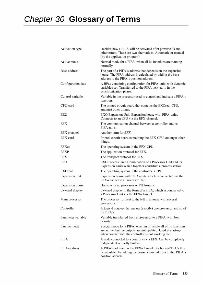
Glossary of Terms 153
Chapter 30 Glossary of Terms
Activation type Decides how a PIFA will be activated after power cuts and other errors. There are two alternatives: Automatic or manual (by the application program).
Active mode Normal mode for a PIFA, when all its functions are running normally.
Base address The part of a PIFA’s address that depends on the expansion house. The PIFA-address is calculated by adding the base address to the PIFA’s position address.
Configuration data A BPac containing configuration for PIFA-units with dynamic variables set. Transferred to the PIFA very early in the synchronization phase.
Control variable Variable in the processor used to control and indicate a PIFA’s function.
CPU-card The printed circuit board that contains the EXOreal-CPU, amongst other things.
EEU EXO Expansion Unit. Expansion house with PIFA-units. Connects to an EPU via the EFX-channel.
EFX The communication channel between a controller and its PIFA-units.
EFX-channel Another term for EFX. EFX-card Printed circuit board containing the EFX-CPU, amongst other
things. EFXos The operating system in the EFX-CPU EFXP The application protocol for EFX. EFXT The transport protocol for EFX. EPU EXO Process Unit. Combination of a Processor Unit and its
Expansion Units which together constitute a process station. EXOreal The operating system in the controller’s CPU. Expansion unit Expansion house with PIFA-units which is connected via the
EFX-channel to a Processor Unit. Expansion house House with no processor or PIFA-units. External display External display in the form of a PIFA, which is connected to
a Processor Unit via the EFX-channel. Main processor The processor furthest to the left in a house with several
processors. Controller A logical concept that means (exactly) one processor and all of
its PIFA’s. Parameter variable Variable transferred from a processor to a PIFA, with low
priority. Passive mode Special mode for a PIFA, when in principle all of its functions
are active, but the outputs are not updated. Used at start-up when contact with the controller is not working etc.
PIFA A node connected to a controller via EFX. Can be completely independent or partly built-in
PIFA-address A PIFA’s address on the EFX-channel. For house-PIFA’s this is calculated by adding the house’s base address to the PIFA’s position address.

154 Part VII Appendix
PIFAos The operating system in an intelligent PIFA that communicates with the processor via EFX.
Position address The part of a PIFA’s address that depends on the position in the house. The PIFA-address is calculated by adding the house’s base address to the position address.
Processor A physical concept that describes the central functions in a controller, i.e. the CPU and EFX-cards together.
Processor unit House with processor and PIFA-units. Processor house House with processor, but no PIFA-units. Program A number of EXOL-files in the controller that comprise the
actual application. Read variable Variable whose value is transferred from a PIFA to the
processor. Resource Smallest functional peripheral unit in a controller, e.g. an
analog input or a display. Resource attribute Software property for a resource. Resource name The resource’s name in the software. Resource type Standardized classification for resources with the same
function. Section Part of a house, with space for 2 PIFA-units. Station Logical concept that covers one or more controllers (and
computers) organized in a functional group. There are process stations and computer station.
Write variable Variable that is transferred from a processor to a PIFA, with high priority.

Glossary of Terms 155
PPaarrtt VVIIIIII IInnddeexx

156 Part VIII Index
A Active Transmitters 39 Add a PIFA 48 Addresses 41 Addressing PIFA-units 23 Advanced inputs 62 Alarm Points 99 Analog inputs 72 Analog outputs 76 Application Interface 50
B Battery 25, 57, 132 Battery charger 147 Battery, changing 132 Beeper 81
C Cabinet Installations 31 Cardholders for Signal Descriptions 13 Changing the battery 132 Character sets 82 Clock 57 Commissioning 41 Common Properties for PIFA-units 107 Communication 59 Communication Buses & Interfaces 36 Communication Disturbance 54 Communication Ports 107 Compensation for wire resistance 72 Complete EXOflex units 129 Configuration 47
Analog inputs 74 Analog outputs 77 Digital inputs 65 Digital outputs 70 PIFA units 49 TCP/IP 85
Connection to power supply 33 Connections 59
Modem 9011 117 Control variables 52 Controller Objects 96 Counter variables 51
D DC units 33 Declaration of conformity 152 Digital inputs 62 Digital inputs and outputs on the power-PIFA 58 Digital outputs 67
Dimensions 102 Display 79, 96 Distributed Processor Power 24
E EFX channel 56 EFX PIFA units 49 EFX-PIFA-units 47 EIB 147 Electrical formats 59 Electromagnetic Compatibility 152 EMC and LVD Directives 152 EPU 8 EPU internal design 22 E-signal 36 Ethernet Interface 37 Ethernet-address 91 EXOflex
Introduction 8 EXOflex House 9 EXOL Processor 11 EXOline 36 Exomatic Processor Unit 8 EXOreal 56 External display 79 External Display 20 External Modem 144
F Firewalls 94 Frequency generation
Digital outputs 68 Function
Analog inputs 72 Analog outputs 76 Digital inputs 62 Digital outputs 67
Function diagram Digital inputs 65
Function Diagram Analog inputs 74 Analog outputs 77 Digital outputs 70
G Glossary 153
H Hardware clock 57 hlEXOline 37 Horizontal Rail-mounting 16
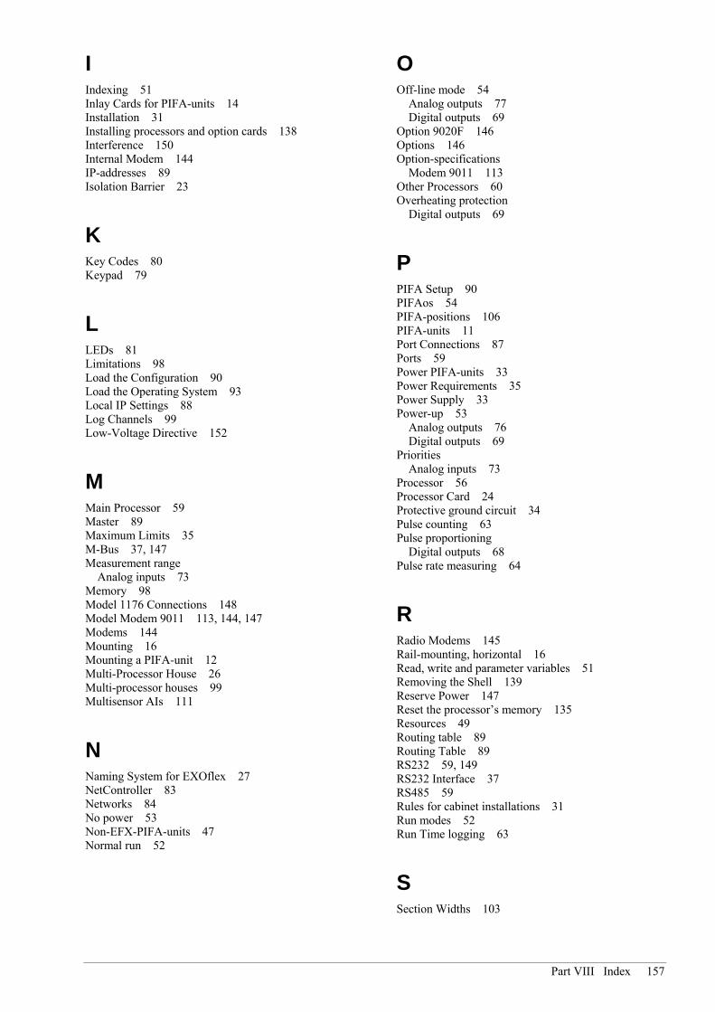
Part VIII Index 157
I Indexing 51 Inlay Cards for PIFA-units 14 Installation 31 Installing processors and option cards 138 Interference 150 Internal Modem 144 IP-addresses 89 Isolation Barrier 23
K Key Codes 80 Keypad 79
L LEDs 81 Limitations 98 Load the Configuration 90 Load the Operating System 93 Local IP Settings 88 Log Channels 99 Low-Voltage Directive 152
M Main Processor 59 Master 89 Maximum Limits 35 M-Bus 37, 147 Measurement range
Analog inputs 73 Memory 98 Model 1176 Connections 148 Model Modem 9011 113, 144, 147 Modems 144 Mounting 16 Mounting a PIFA-unit 12 Multi-Processor House 26 Multi-processor houses 99 Multisensor AIs 111
N Naming System for EXOflex 27 NetController 83 Networks 84 No power 53 Non-EFX-PIFA-units 47 Normal run 52
O Off-line mode 54
Analog outputs 77 Digital outputs 69
Option 9020F 146 Options 146 Option-specifications
Modem 9011 113 Other Processors 60 Overheating protection
Digital outputs 69
P PIFA Setup 90 PIFAos 54 PIFA-positions 106 PIFA-units 11 Port Connections 87 Ports 59 Power PIFA-units 33 Power Requirements 35 Power Supply 33 Power-up 53
Analog outputs 76 Digital outputs 69
Priorities Analog inputs 73
Processor 56 Processor Card 24 Protective ground circuit 34 Pulse counting 63 Pulse proportioning
Digital outputs 68 Pulse rate measuring 64
R Radio Modems 145 Rail-mounting, horizontal 16 Read, write and parameter variables 51 Removing the Shell 139 Reserve Power 147 Reset the processor’s memory 135 Resources 49 Routing table 89 Routing Table 89 RS232 59, 149 RS232 Interface 37 RS485 59 Rules for cabinet installations 31 Run modes 52 Run Time logging 63
S Section Widths 103

158 Part VIII Index
Security 84 Serial number 55 Serial Ports 25 Set the Processor’s Address 92 Setting Addresses 41 Signal Descriptions 13 SIOX bus 37 Slave 90 SO Interface 38 Specifications
Communication ports 107 Enclosure 102 Environment 104 General for PIFAs 106 Modem 9011 114 Processor 105
Spontaneous warm-start 54 Standard 24V DC Digital Inputs 109 Standard 24V DC Digital Outputs 110 Standard Analog Outputs 111 Station Handler 97 System variables 61 System Variables
External Display 80, 81
T TCP/IP 83
TCP/IP Gateway 84 Telephone Modems 144 Texts 98 Three-Wire Current Sink Transmitter (NPN-type) 40 Three-Wire Transmitter (PNP-type) 40 Time Schedules Display 97 Two-Wire Transmitter 39
U UPS 147
V,W Wall mounting 18 Variables
Analog inputs 75 Analog outputs 78 Digital inputs 66 Digital outputs 70
Vertical Mounting 19 Wiring
Modem 9011 117

Part VIII Index 159

160 Part IX Regin Resellers
PPaarrtt IIXX RReeggiinn RReesseelllleerrss

Part IX Regin Resellers 161
For information on Regin Resellers, please visit the Regin Website: www.regin.se