experiment 4
DESCRIPTION
Experiment 4. * Part A: Introduction to Operational Amplifiers * Part B: Voltage Followers * Part C: Integrators and Differentiators * Part D: Amplifying the Strain Gauge Signal. Part A Introduction to Operational Amplifiers. Operational Amplifiers Op-Amp Circuits The Inverting Amplifier - PowerPoint PPT PresentationTRANSCRIPT
Electronic InstrumentationExperiment 4
* Part A: Introduction to Operational Amplifiers
* Part B: Voltage Followers
* Part C: Integrators and Differentiators
* Part D: Amplifying the Strain Gauge Signal
Part AIntroduction to Operational
Amplifiers
Operational Amplifiers Op-Amp Circuits
• The Inverting Amplifier
• The Non-Inverting Amplifier
Operational Amplifiers Op-Amps are possibly the most
versatile linear integrated circuits used in analog electronics.
The Op-Amp is not strictly an element; it contains elements, such as resistors and transistors.
However, it is a basic building block, just like R, L, and C.
We treat this complex circuit as a black box.
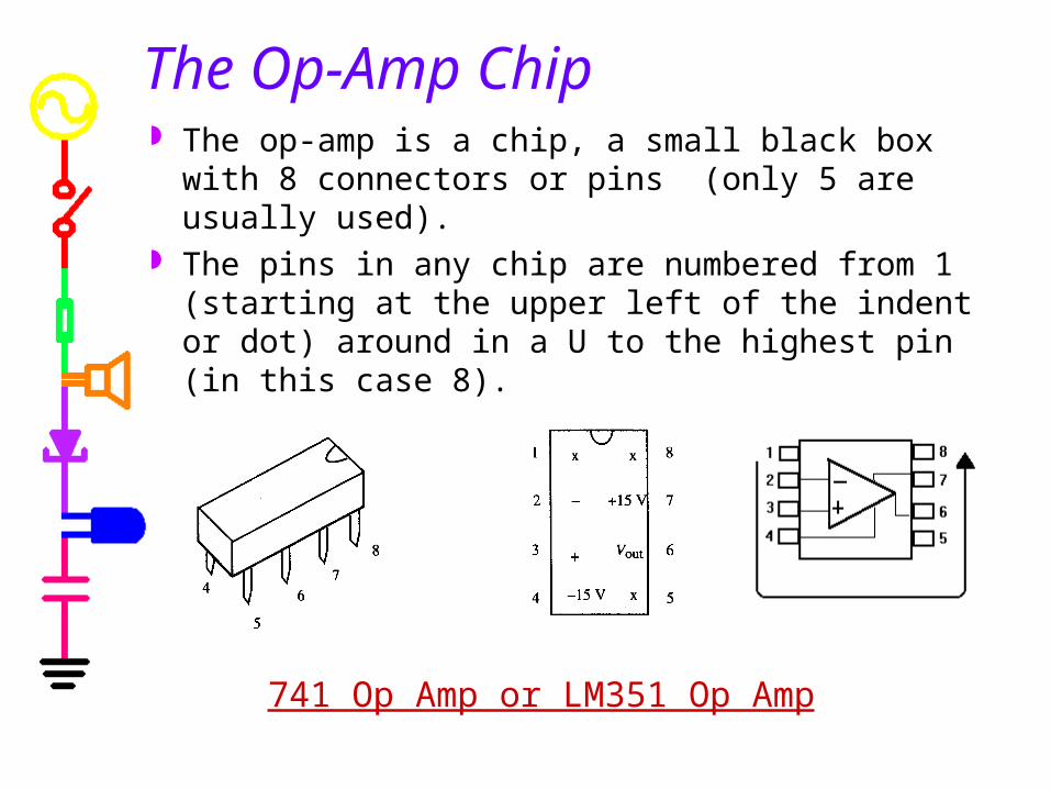
The Op-Amp Chip The op-amp is a chip, a small black box with 8
connectors or pins (only 5 are usually used). The pins in any chip are numbered from 1
(starting at the upper left of the indent or dot) around in a U to the highest pin (in this case 8).
741 Op Amp or LM351 Op Amp

Op-Amp Input and Output The op-amp has two inputs, an inverting input (-) and a
non-inverting input (+), and one output. The output goes positive when the non-inverting input (+)
goes more positive than the inverting (-) input, and vice versa.
The symbols + and – do not mean that that you have to keep one positive with respect to the other; they tell you the relative phase of the output. (Vin=V1-V2)
A fraction of a millivolt between the input terminals will
swing the output over its full range.
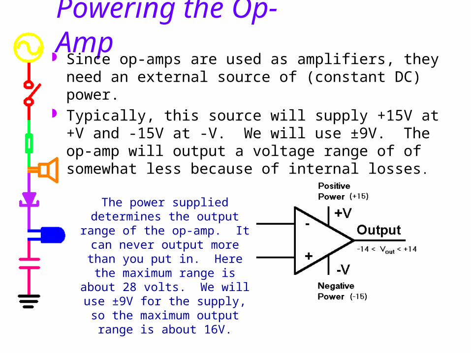
Powering the Op-Amp Since op-amps are used as amplifiers, they need
an external source of (constant DC) power. Typically, this source will supply +15V at +V and
-15V at -V. We will use ±9V. The op-amp will output a voltage range of of somewhat less because of internal losses.
The power supplied determines the output range of the op-amp. It can never output more than you put in. Here the maximum range is about 28 volts. We will use ±9V for the supply, so the maximum output
range is about 16V.

Op-Amp Intrinsic Gain Amplifiers increase the magnitude of a signal by
multiplier called a gain -- “A”. The internal gain of an op-amp is very high. The
exact gain is often unpredictable. We call this gain the open-loop gain or intrinsic
gain.
The output of the op-amp is this gain multiplied by the input
5 6outopen loop
in
VA 10 10
V
21 VVAVAV olinolout
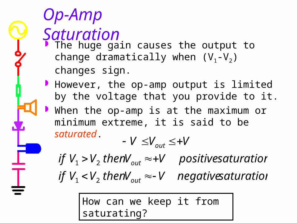
Op-Amp Saturation The huge gain causes the output to change
dramatically when (V1-V2) changes sign.
However, the op-amp output is limited by the voltage that you provide to it.
When the op-amp is at the maximum or minimum extreme, it is said to be saturated.
saturationnegativeVVthenVVif
saturationpositiveVVthenVVif
VVV
out
out
out
21
21
How can we keep it from saturating?
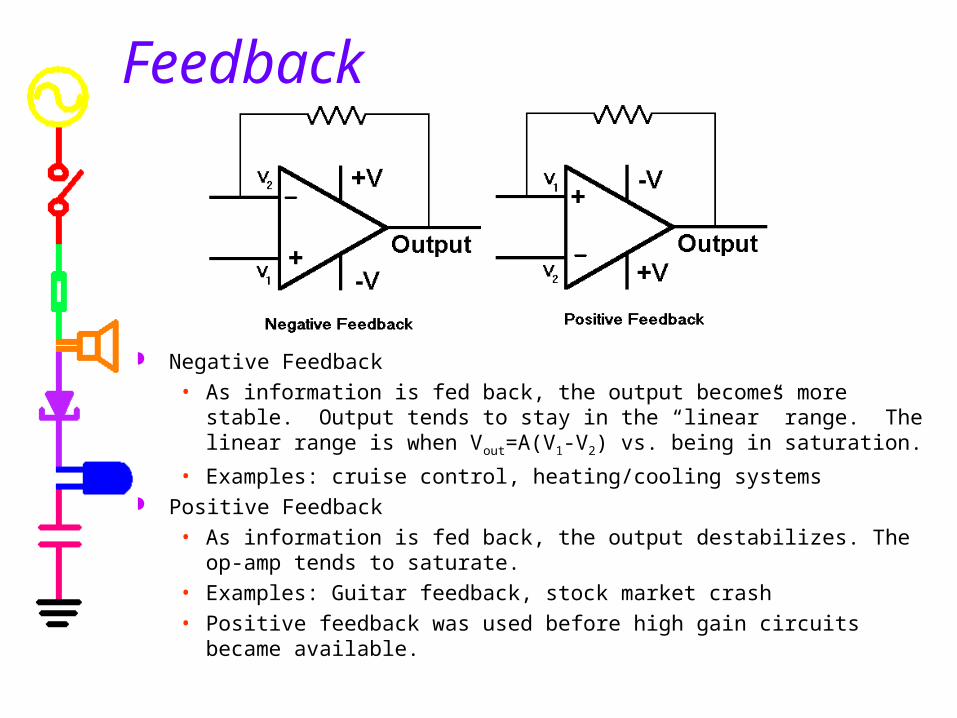
Feedback
Negative Feedback
• As information is fed back, the output becomes more stable. Output tends to stay in the “linear” range. The linear range is when Vout=A(V1-V2) vs. being in saturation.
• Examples: cruise control, heating/cooling systems Positive Feedback
• As information is fed back, the output destabilizes. The op-amp tends to saturate.
• Examples: Guitar feedback, stock market crash
• Positive feedback was used before high gain circuits became available.

Op-Amp Circuits use Negative Feedback
Negative feedback couples the output back in such a way as to cancel some of the input.
Amplifiers with negative feedback depend less and less on the open-loop gain and finally depend only on the properties of the values of the components in the feedback network.
The systems gives up excessive gain to improve predictability and reliability.

Op-Amp Circuits Op-Amps circuits can perform mathematical
operations on input signals:• addition and subtraction• multiplication and division• differentiation and integration
Other common uses include:• Impedance buffering• Active filters• Active controllers• Analog-digital interfacing
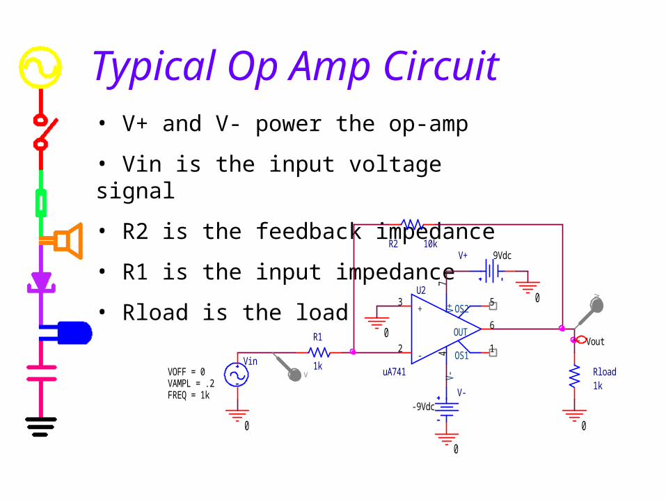
Typical Op Amp Circuit• V+ and V- power the op-amp
• Vin is the input voltage signal
• R2 is the feedback impedance
• R1 is the input impedance
• Rload is the load U2
uA741
+3
-2
V+7
V-4
OUT6
OS11
OS25
R1
1k Rload1k
V+ 9Vdc
V--9Vdc
0
0
0
0
0
Vout
R2 10k
Vin
FREQ = 1kVAMPL = .2VOFF = 0
V
V
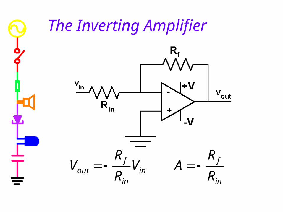
in
fin
in
fout R
RAV
R
RV
The Inverting Amplifier
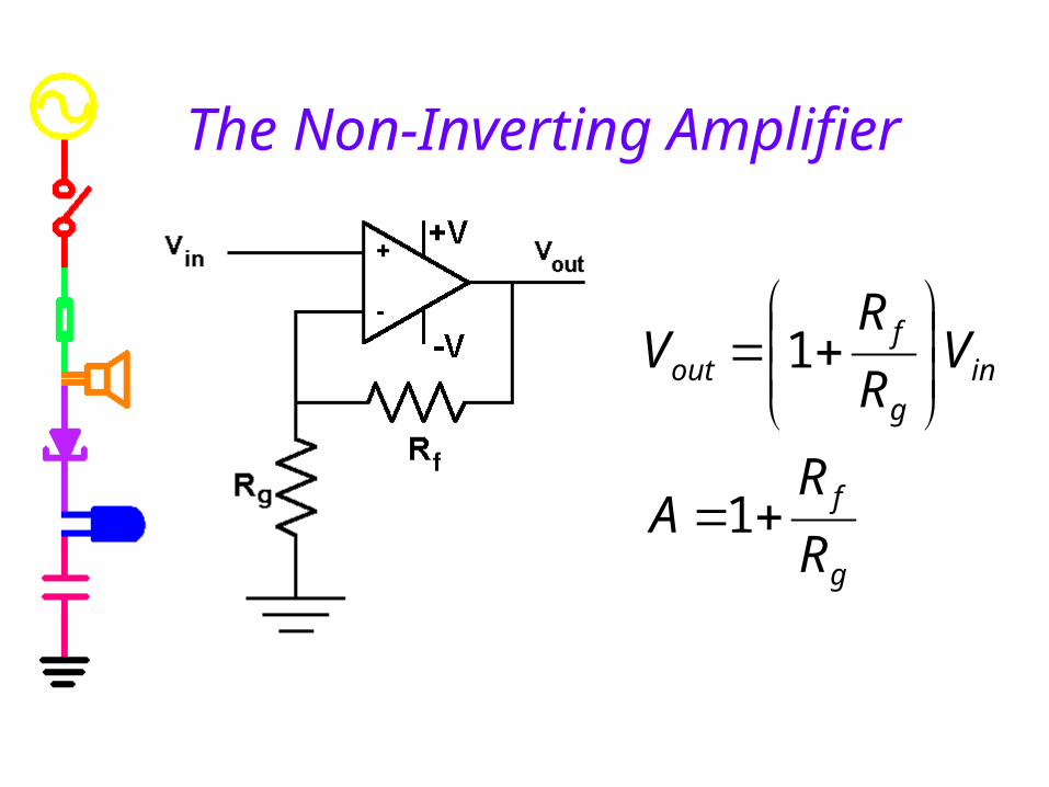
g
f
ing
fout
R
RA
VR
RV
1
1
The Non-Inverting Amplifier
Remember to disconnect the batteries.
End of part A
Part BThe Voltage Follower
Op-Amp Analysis Voltage Followers

Op-Amp Analysis
We assume we have an ideal op-amp:• infinite input impedance (no current at inputs)
• zero output impedance (no internal voltage losses)
• infinite intrinsic gain
• instantaneous time response
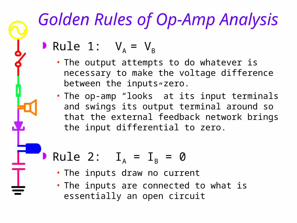
Golden Rules of Op-Amp Analysis
Rule 1: VA = VB
• The output attempts to do whatever is necessary to make the voltage difference between the inputs zero.
• The op-amp “looks” at its input terminals and swings its output terminal around so that the external feedback network brings the input differential to zero.
Rule 2: IA = IB = 0• The inputs draw no current
• The inputs are connected to what is essentially an open circuit

1) Remove the op-amp from the circuit and draw two circuits (one for the + and one for the – input terminals of the op amp).
2) Write equations for the two circuits.
3) Simplify the equations using the rules for op amp analysis and solve for Vout/Vin
Steps in Analyzing Op-Amp Circuits
Why can the op-amp be removed from the circuit?
• There is no input current, so the connections at the inputs are open circuits.
• The output acts like a new source. We can replace it by a source with a voltage equal to Vout.
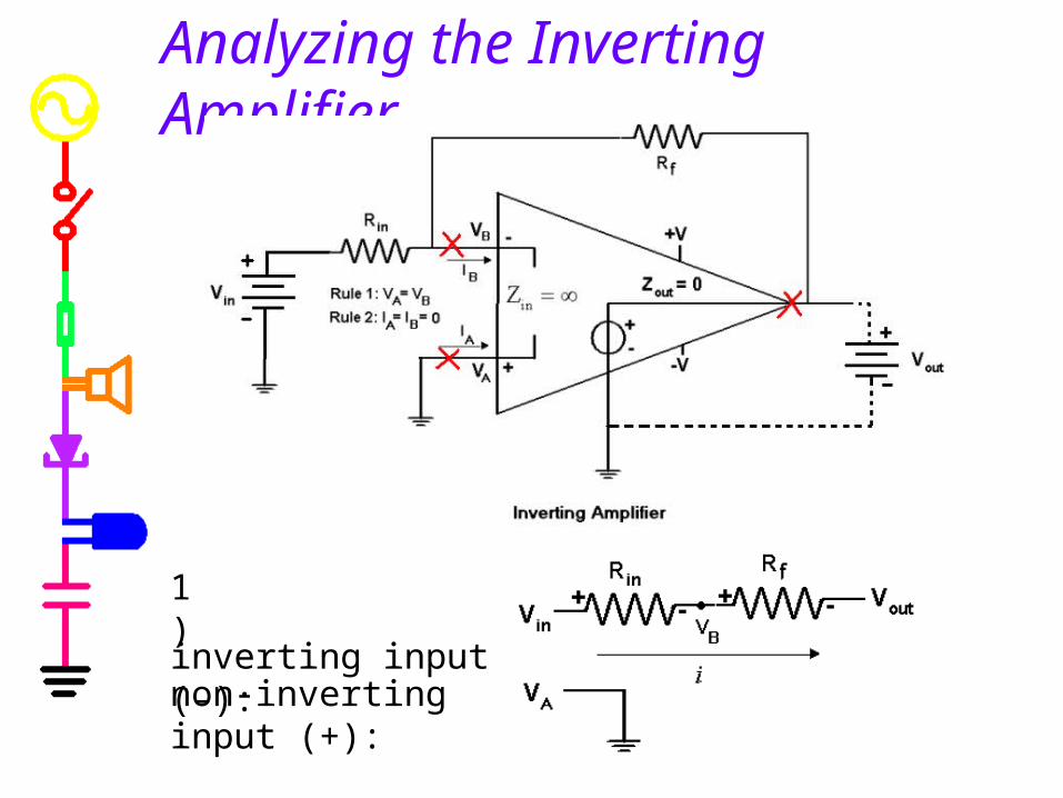
Analyzing the Inverting Amplifier
inverting input (-):
non-inverting input (+):
1)

How to handle two voltage sources
outBRf
BinRin
VVV
VVV
inf
foutinRf
inf
inoutinRin
RR
RVVV
RR
RVVV
VVVVVkk
kVVV RfoutBRf 5.45.1
13
335
:
:)1
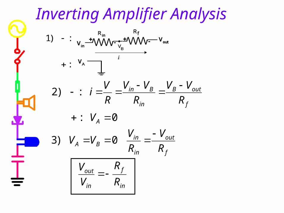
Inverting Amplifier Analysis
in
f
in
out
f
out
in
inBA
A
f
outB
in
Bin
R
R
V
V
R
V
R
VVV
V
R
VV
R
VV
R
Vi
0)3
0:
:)2

Analysis of Non-Inverting Amplifier
g
f
in
out
g
gf
in
out
outgf
ginBA
outgf
gB
inA
R
R
V
V
R
RR
V
V
VRR
RVVV
VRR
RV
VV
1
)3
:
:)2
Note that step 2 uses a voltage divider to find the voltage at VB relative to the output voltage.
:
:)1

inoutBA
inBoutA
VVthereforeVV
VVVV
analysis
,
]2]1
:
1in
out
V
V
The Voltage Follower

Why is it useful?
In this voltage divider, we get a different output depending upon the load we put on the circuit.
Why?
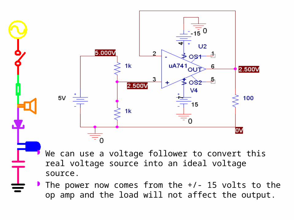
We can use a voltage follower to convert this real voltage source into an ideal voltage source.
The power now comes from the +/- 15 volts to the op amp and the load will not affect the output.
Part CIntegrators and Differentiators
General Op-Amp Analysis Differentiators Integrators Comparison

Golden Rules of Op-Amp Analysis
Rule 1: VA = VB
• The output attempts to do whatever is necessary to make the voltage difference between the inputs zero.
• The op-amp “looks” at its input terminals and swings its output terminal around so that the external feedback network brings the input differential to zero.
Rule 2: IA = IB = 0• The inputs draw no current
• The inputs are connected to what is essentially an open circuit
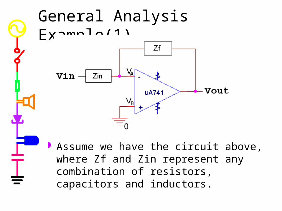
General Analysis Example(1)
Assume we have the circuit above, where Zf and Zin represent any combination of resistors, capacitors and inductors.
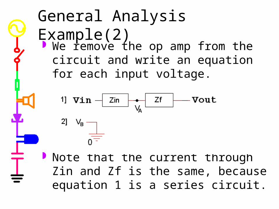
We remove the op amp from the circuit and write an equation for each input voltage.
Note that the current through Zin and Zf is the same, because equation 1 is a series circuit.
General Analysis Example(2)
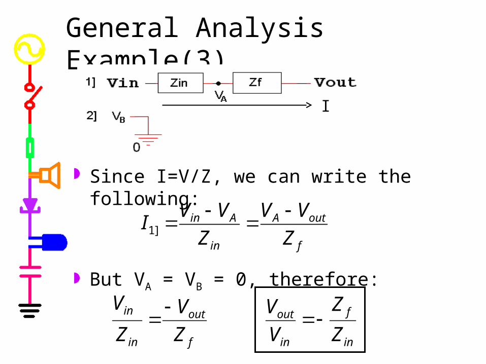
Since I=V/Z, we can write the following:
But VA = VB = 0, therefore:
General Analysis Example(3)
f
outA
in
Ain
Z
VV
Z
VVI
]1
in
f
in
out
f
out
in
in
Z
Z
V
V
Z
V
Z
V
I

For any op amp circuit where the positive input is grounded, as pictured above, the equation for the behavior is given by:
General Analysis Conclusion
in
f
in
out
Z
Z
V
V
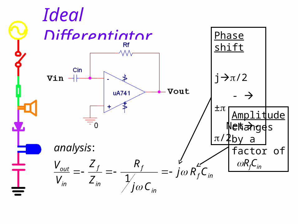
Ideal Differentiator
inf
in
f
in
f
in
out CRj
Cj
R
Z
Z
V
V
analysis
1
:
Phase shift
j/2
- ±
Net-/2
Amplitude changes by a factor of RfCin
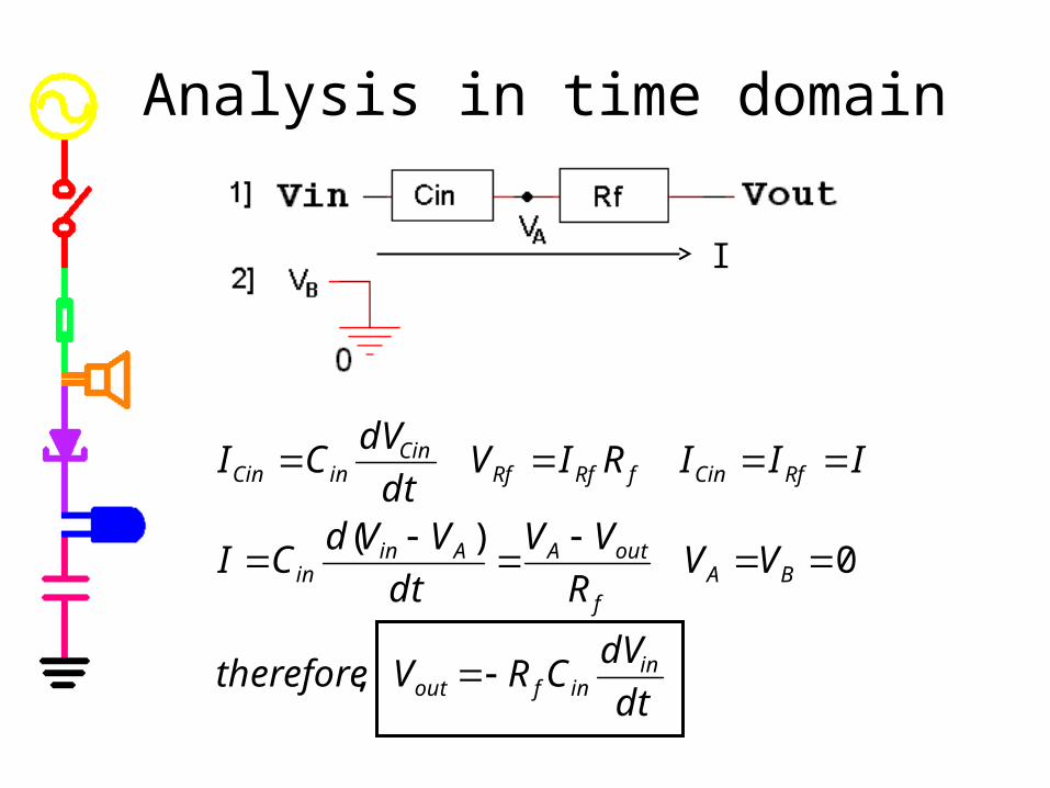
Analysis in time domain
dt
dVCRVtherefore
VVR
VV
dt
VVdCI
IIIRIVdt
dVCI
ininfout
BAf
outAAinin
RfCinfRfRfCin
inCin
,
0)(
I

Problem with ideal differentiator
Circuits will always have some kind of input resistance, even if it is just the 50 ohms from the function generator.
RealIdeal

ininin Cj
RZ
1
Analysis of real differentiator
11
inin
inf
inin
f
in
f
in
out
CRj
CRj
CjR
R
Z
Z
V
V
Low Frequencies High Frequencies
infin
out CRjV
V
ideal differentiator
in
f
in
out
R
R
V
V
inverting amplifier
I
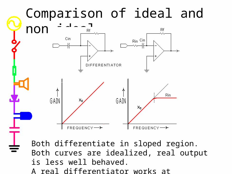
Comparison of ideal and non-ideal
Both differentiate in sloped region.Both curves are idealized, real output is less well behaved.A real differentiator works at frequencies below c=1/RinCin
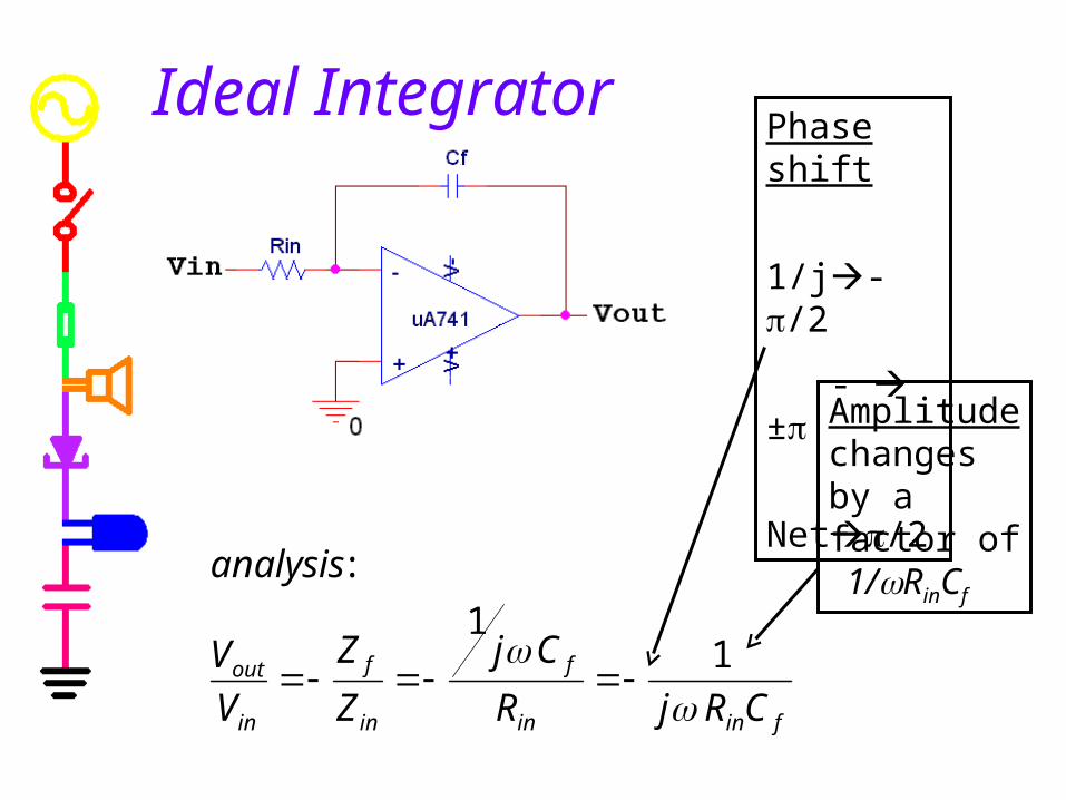
Ideal Integrator
finin
f
in
f
in
out
CRjR
Cj
Z
Z
V
V
analysis
1
1
:
Phase shift
1/j-/2
- ±
Net/2
Amplitude changes by a factor of 1/RinCf
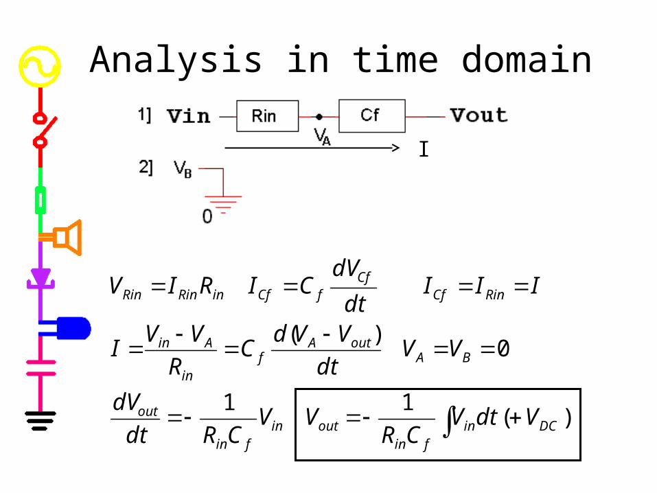
Analysis in time domain
)(11
0)(
DCinfin
outinfin
out
BAoutA
fin
Ain
RinCfCf
fCfinRinRin
VdtVCR
VVCRdt
dV
VVdt
VVdC
R
VVI
IIIdt
dVCIRIV
I
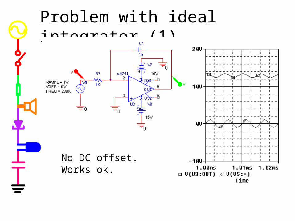
Problem with ideal integrator (1)
No DC offset.Works ok.
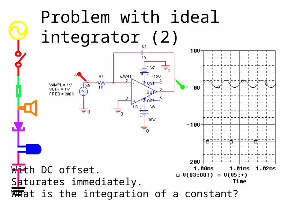
Problem with ideal integrator (2)
With DC offset.Saturates immediately.What is the integration of a constant?
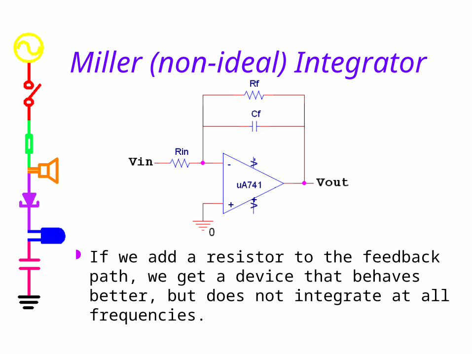
Miller (non-ideal) Integrator
If we add a resistor to the feedback path, we get a device that behaves better, but does not integrate at all frequencies.

Low Frequencies High Frequencies
in
f
in
f
in
out
R
R
Z
Z
V
V
RinCfjZ
Z
V
V
in
f
in
out
1
inverting amplifier ideal integrator
The influence of the capacitor dominates at higher frequencies. Therefore, it acts as an integrator at higher frequencies, where it also tends to attenuate (make less) the signal.
Behavior of Miller integrator

11
1
ff
f
ff
ff
f CRj
R
CjR
CjR
Z
Analysis of Miller integrator
inffin
f
in
ff
f
in
f
in
out
RCRRj
R
R
CRj
R
Z
Z
V
V
1
Low Frequencies High Frequencies
in
f
in
out
R
R
V
V
inverting amplifier
finin
out
CRjV
V
1
ideal integrator
I

Comparison of ideal and non-ideal
Both integrate in sloped region.Both curves are idealized, real output is less well behaved.A real integrator works at frequencies above c=1/RfCf

Problem solved with Miller integrator
With DC offset.Still integrates fine.
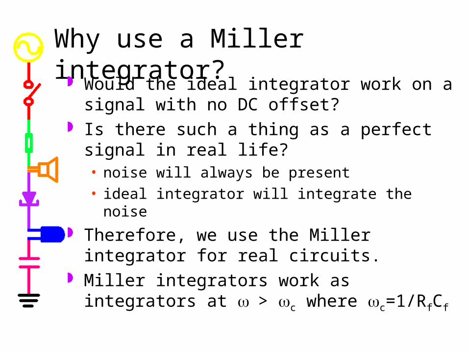
Why use a Miller integrator? Would the ideal integrator work on a signal with
no DC offset? Is there such a thing as a perfect signal in real
life?• noise will always be present
• ideal integrator will integrate the noise
Therefore, we use the Miller integrator for real circuits.
Miller integrators work as integrators at > c where c=1/RfCf

Comparison Differentiaion Integration original signal
v(t)=Asin(t) v(t)=Asin(t)
mathematically
dv(t)/dt = Acos(t) v(t)dt = -(A/cos(t)
mathematical phase shift
+90 (sine to cosine) -90 (sine to –cosine)
mathematical amplitude change
1/
H(j H(j jRC H(j jRC = j/RC electronic phase shift
-90 (-j) +90 (+j)
electronic amplitude change
RC RC
The op amp circuit will invert the signal and multiply the mathematical amplitude by RC (differentiator) or 1/RC (integrator)
Part DAdding and Subtracting Signals
Op-Amp Adders Differential Amplifier Op-Amp Limitations Analog Computers
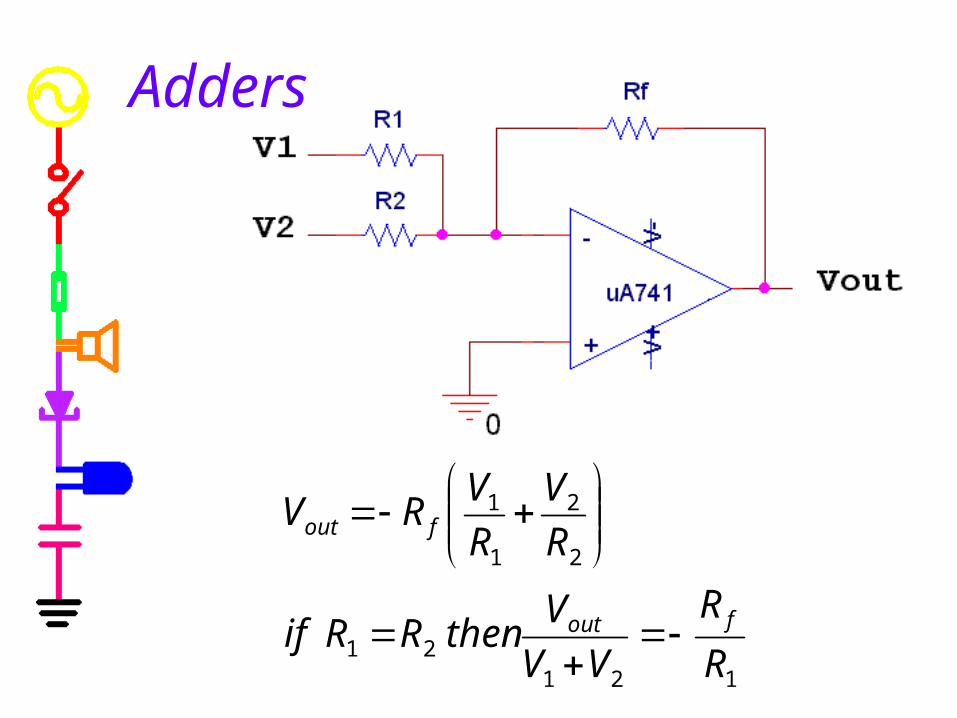
Adders
12121
2
2
1
1
R
R
VV
VthenRRif
R
V
R
VRV
fout
fout
Weighted Adders Unlike differential amplifiers, adders are
also useful when R1<>R2.
This is called a “Weighted Adder” A weighted adder allows you to combine
several different signals with a different gain on each input.
You can use weighted adders to build audio mixers and digital-to-analog converters.
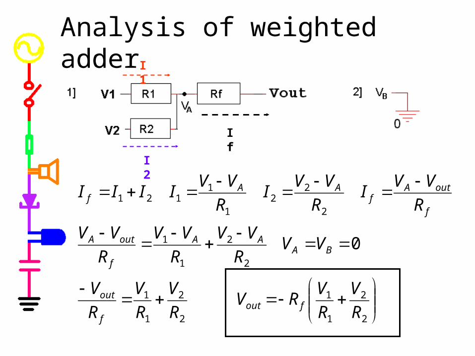
Analysis of weighted adder
I2
I1
If
2
2
1
1
2
2
1
1
2
2
1
1
2
22
1
1121
0
R
V
R
VRV
R
V
R
V
R
V
VVR
VV
R
VV
R
VV
R
VVI
R
VVI
R
VVIIII
foutf
out
BAAA
f
outA
f
outAf
AAf

Differential (or Difference) Amplifier
in
f
in
fout R
RAVV
R
RV
)( 12
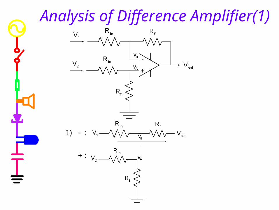
Analysis of Difference Amplifier(1)
:
:)1
in
fout
outinffoutinf
in
inf
f
fin
fBA
outinf
in
inf
fB
fin
inf
fin
outinf
B
fin
f
out
inBB
fin
fA
f
outB
in
B
R
R
VV
V
VRVRVRVRR
RV
RR
RV
RR
RVV
VRR
RV
RR
RV
RR
RR
RR
VRVR
V
RR
R
V
RV
VVforsolve
VRR
RV
R
VV
R
VVi
12
1212
1
11
2
1
:
11:)3
:
:)2
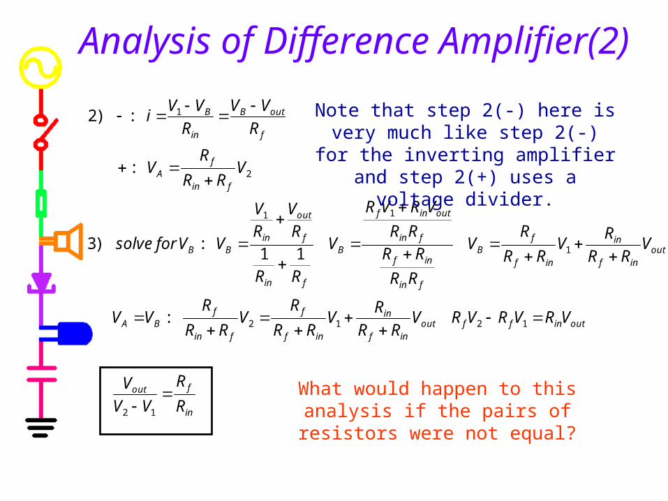
Analysis of Difference Amplifier(2)
Note that step 2(-) here is very much like step 2(-) for the inverting amplifier
and step 2(+) uses a voltage divider.
What would happen to this analysis if the pairs of resistors were not equal?

Op-Amp Limitations
Model of a Real Op-Amp Saturation Current Limitations Slew Rate
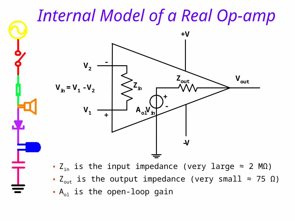
Internal Model of a Real Op-amp
• Zin is the input impedance (very large ≈ 2 MΩ)
• Zout is the output impedance (very small ≈ 75 Ω)
• Aol is the open-loop gain
Vout
V2
+V
-V
-+
V1
Vin = V1 - V2Zin
Zout
+
-
AolVin

Saturation Even with feedback,
• any time the output tries to go above V+ the op-amp will saturate positive.
• Any time the output tries to go below V- the op-amp will saturate negative.
Ideally, the saturation points for an op-amp are equal to the power voltages, in reality they are 1-2 volts less.
VVV out Ideal: -15 < Vout < +15
Real: -14 < Vout < +14

Additional Limitations Current Limits If the load on the op-amp is
very small, • Most of the current goes through the load• Less current goes through the feedback path• Op-amp cannot supply current fast enough• Circuit operation starts to degrade
Slew Rate• The op-amp has internal current limits and internal
capacitance. • There is a maximum rate that the internal capacitance
can charge, this results in a maximum rate of change of the output voltage.
• This is called the slew rate.
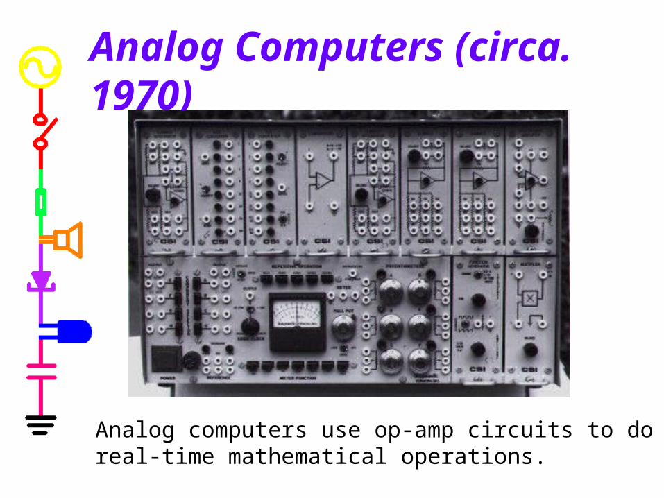
Analog Computers (circa. 1970)
Analog computers use op-amp circuits to do real-time mathematical operations.

Using an Analog Computer
Users would hard wire adders, differentiators, etc. using the internal circuits in the computer to perform whatever task they wanted in real time.

Analog vs. Digital Computers In the 60’s and 70’s analog and digital computers competed. Analog
• Advantage: real time
• Disadvantage: hard wired Digital
• Advantage: more flexible, could program jobs
• Disadvantage: slower Digital wins
• they got faster
• they became multi-user
• they got even more flexible and could do more than just math

Now analog computers live in museums with old digital computers:
Mind Machine Web Museum: http://userwww.sfsu.edu/%7Ehl/mmm.htmlAnalog Computer Museum: http://dcoward.best.vwh.net/analog/index.html