experimental and computational study of … · engineering and mechanics, international research...
TRANSCRIPT

Experimental and Computational Study of Microstructural Effect on
Ductile Fracture of Hot-Forming Materials
Yang Liu1, Yiguo Zhu1,, Caglar Oskay2, Ping Hu1, Liang Ying1 and Dantong Wang1
1. State Key Laboratory of Structural Analysis for Industrial Equipment, Faculty of Vehicle
Engineering and Mechanics, International Research Center for Computational Mechanics,
Dalian University of Technology, Dalian 116024, People’s Republic of China
2. Department of Civil and Environmental Engineering,
Vanderbilt University, Nashville, TN 37235
Abstract: Thermo-mechanical experiments at different elevated temperatures are carried out for
tensile and shear-dominant specimens extracted from warming forming materials of 7075 aluminum
alloy and 22MnB5 boron steel, respectively. A specimen-embedded furnace jointed by temp-control
system to perform the high temperature shear experiments. Driven by microscale anisotropic plastic
flow, damage is embedded in each slip system and damage evolution is controlled by the preferential
dislocation slip. Combined with microscale damage and dislocation density based constitutive
model, an advanced crystal plasticity method is proposed to perform predictions of mechanical
behavior of face-center-cubic materials at various temperatures. Reasonable agreement is obtained
between experimental and numerical results for different specimens, temperature conditions and
materials. This approach simultaneously captures the strain hardening rate, damage softening, non-
linear post-necking and fracture strain. Microstructural effects on ductile fracture are tracked and
investigated including dislocation density and crystallographic orientation. The results show that
local dislocation density rise is associated with damage initiation. Different fracture morphologies
and necking paths are caused by distinct initial misorientation distributions in comparison with
experimental observation of 7075 aluminum alloy. Local misorientations are investigated and
critical misorientation ranges are computed for promoting void growth in zigzag and straight
fracture morphologies. Schmid factor is computed as not necessary variable to trigger void growth.
Keywords
Polycrystalline Material; Crystal Plasticity; Constitutive Behavior; Dislocation Density; Microscale
Damage; Thermo-mechanical Processes;
1. Introduction
Warm forming and hot stamping technologies are widely used for production of lightweight, low
spring back and high strength structural components [1,2]. Warm forming for aluminum alloy (AA)
is usually conducted in temperature range of 473K to 623K [2] and hot stamping for boron steel
(BS) is performed at 873K to 1173K [3]. At these temperature ranges, these two alloys remain
mostly face-centered cubic (FCC). During thermo-mechanical loading of these two alloys, an
experimental-numerical approach is proved to be effective and efficient in studying the performance
of damage [4,5], strain rate and temperature effects [6–12]. To the best of our knowledge, the
previous investigations were performed based on phenomenological models, and the fundamental
relationships between microstructure and thermo-mechanical responses have not been established.
In metallurgical deformation of polycrystalline materials, the anisotropic plastic behavior is a
Corresponding author. Tel: 86-411-84707330, Fax: 86-411-84708390
E-mail address: [email protected]

primary mechanism. Because of the crystallographic anisotropy, macroscopic phenomenon such as
damage evolution, strain hardening and material yield strength is orientation-dependent [13–15]. In
recent years, crystal plasticity finite element (CPFE) method has progressed as an effective scheme
for modeling polycrystalline anisotropy and localized plastic flow. It has been validated by
microscopic detection technologies including scanning electron microscope (SEM) [14,16,17], X-
ray diffraction (XRD) [18], transmission electron microscopy (TEM) [19] and electron backscatter
diffraction (EBSD) [20–25]. In combination with discrete Green’s function fast Fourier transform
(FFT) and spectral interpolation, CPFE model can efficiently and accurately obtain the grain-
orientation-dependent mechanism at the phase or grain interface [26,27].
The interaction between void growth and dislocation mechanism is first addressed by Steven et
al. concluding that dislocation nucleation may be triggered on slip planes intersecting the void at
points of high shear-stress concentration [28]. In general of ductile material, the damage initiation
and void nucleation are associated with stress enhancement mechanism, involving plastic flow and
dislocation accumulation [29]. To implement the dislocation density in modeling large plastic
deformation leading to ductile fracture, multiple constitutive models are proposed coupled with
crystal plasticity. An advanced dislocation density based strain hardening law was implemented in
the multiscale framework such as visco-plastic self-consistent (VPSC) and elasto-plastic self-
consistent (EPSC) models to predict the anisotropic mechanical response and texture evolution of
polycrystalline materials [30–34]. To consider the rate dependency and thermal effect, Knezevic et
al. [35] proposed a dislocation density based model considering dislocation activity as a function of
temperature and strain rate. Recently, a nonlocal CPFE model combined with dislocation based
model was presented and the density distribution of geometrically necessary dislocation (GND) was
explicitly captured [36] compared with experimental observation in the indentation test of single-
crystalline nickel.
To model the damage initiation and ductile fracture of polycrystalline materials, a
micromechanics-based model, called the Gurson–Tvergaard–Needleman (GTN) model, was
developed and combined with complex constitutive models, such as visco-plasticity [37], crystal
plasticity [38] and strain-gradient plasticity [39]. However, there is a need to identify multiple void-
associated parameters combined with accurate microscale experimental data. Another approach is
the continuum damage mechanics (CDM). Continuum damage model has been widely used for
predicting damage initiation, coalescence and localization phenomena [40–43]. For instance,
geometric, energetic and general CDM damage models were applied in structural steels to describe
the void growth, void shape change and damage energy dissipation in different stages of damage
growth [44–46]. Recently, to account for microstructural features and anisotropic properties
[13,17,19], the CDM model was applied in the CPFE framework. Damage evolution coupled with
CPFE could provide insight into void development at the grain scale. In Ref. [14] the capability of
four simple CDM models were investigated combined with crystal plasticity.
Ductile fracture depends strongly on the extreme values of microstructural characteristics. To
investigate microstructural effects on ductile fracture, computational models have been developed
such as sensitive analysis [47], image-based finite element analysis [48] and micromechanical
modeling [49,50]. Modeling and investigations are mainly focused on the heterogeneous effect of
inclusion or void morphologies [47,48,50] and disperse distributions [39]. However, these
micromechanical-based analysis does not account for the mechanical anisotropy, specifically the
heterogeneity in polycrystalline microstructures. Recently, the damage evolution is assisted by

classical crystal plasticity model to study the effect of non-basal slip in ductile fracture at different
loading directions [51]. But the positive role of microstructural effects on high-temperature ductile
fracture still lack investigation.
The primary goal of this study is to deepen the understanding of the characteristics for underlying
microstructural variables including the (1) crystallographic orientation and the (2) dislocation
density and their effects on the damage initiation and ductile fracture at elevated temperatures. A
micro-damage model is proposed as a function of the accumulated local shear strain in the slip
system. Incorporated with the damage model, a dislocation density based crystal plasticity can
capture the observed plastic deformation localization, local stress concentration, dislocation pile-
ups and void growth within the microstructure. The remainder of this paper is organized as follows.
The material properties and experimental setups are introduced in Section 2. Coupled with
directional micro-damage model, the temperature-dependent crystal plasticity framework is
provided in Section 3. The numerical implementation is illustrated in Section 4. Calibration and
verification of this continuum micro-damage mechanics coupled crystal plasticity finite element
model (CPFE-CDM) are provided for the two alloys in Section 5. The dislocation density
distributions and orientation characteristics are investigated with fracture morphologies and damage
distributions for microstructural analyses in Section 6 and conclusions are provided in Section 7.
2. Experimental Setups
In the experimental aspect, EBSD was conducted to study the phase distribution, orientation-based
microstructure, misorientation data and grain size of 7075 AA and 22MnB5 at room temperature.
To investigate the ductile fracture under elevated temperature of these two alloys, thermo-
mechanical tests were performed and approximate uniform temperature fields were applied in the
large deformation region of the specimen. In addition, SEM was conducted to understand the
morphology and features of the fracture surface.
From the in-situ EBSD measurements, the initial texture of 7075 AA with FCC lattice are
obtained as shown in Fig. 1(a), which are similar to previous observations [52]. The initial
microstructure in 7075 AA mainly contains equiaxed grains and some elongated grains in the rolling
direction. Zn, Cu and Mg are the main alloying elements to form the small precipitates. Since the
micron-scale void growth is studied in context, the precipitates within scales of ten nanometers are
negligible. The mean grain size of 7075 AA is 103.4μm and its grain size barely changes in the
thermal condition, even heating to 773K. The initial microstructure of as-received 22MnB5 consists
of mainly ferrite and pearlite. Pre-heating of the specimen at 900℃ for 5 minutes before tests
ensures that the grain microstructures are fully transformed into austenite FCC crystal structure with
random orientation distribution, as shown in Fig. 1(b). These austenite grains are mostly equiaxed
and their mean grain size is approximately 90μm.
In the thermo-mechanical test, uniform temperature field is applied in the large deformation
region of the specimen. For thermal tensile and shear tests, two kinds of thermal heating equipment
are employed as shown in Fig. 2 and 3. and three duplicates are conducted for each test to ensure
the validity of the experiments. The traditional vertical tensile testing is not suitable for the thermal
experiments due to gravity effect. Thus, horizontal thermal heating equipment is adopted. In thermal
tensile test of 7075 AA shown in Fig. 2, a thermocouple is attached close to the middle section of
the specimen, and the temperature is maintained for 3 minutes by the temperature controlled system.
An extensometer is installed on the specimen to measure the thermal strain. The mechanical curves

of 7075 AA are shown in Fig. 4(a). In order to be completely austenized by the heating process, the
22MnB5 BS shear specimen is placed in the heating furnace in Fig. 3. The white inside the furnace
is asbestos for preventing heat transfer and preserving heat. Since the specimen is contained in the
furnace, extensometer is hard to attach onto the shear specimen. Thus, in the shear tests of 22MnB5
BS, the stress-versus-strain curves are replaced by force-versus-displacement ones in Fig. 4(b).
(a) (b)
Fig. 1 Initial orientation distributions in pole figures: (a) 7075AA; (b) 22MnB5 steel
Fig. 2 The thermal tensile experiment with the thermocouple attached to the specimen and the
temperature-control system (tensile test for 7075 AA and 22MnB5 BS)
Fig. 3 The thermal shear equipment with the heating furnace. Heat preserving asbestos (white) and
horizontal mechanical stretcher are incorporated (shear test for 22MnB5 BS)

(a) (b)
Fig. 4 The mechanical curves in thermo-mechanical tests. (a) engineering stress-strain curves of
7075 AA; (b) force-vesus-displacement curves of 22MnB5.
In the realistic hot stamping process, phase transformation may happen due to excessive cooling
rate during stamping. As a schematic temperature variation shown in Fig. 5 (a), the temperature of
22MnB5 sheet is maintained at approximately 900℃ for 5 minutes in furnace for austenite
preparation. Then the sheet is directly transferred into stamping step. After stamping, the
temperature of the sheet is lowered down to room temperature and phase transformation from
austenite to martensite occurs during this step to obtain high strength and hardness of the material.
It should be noted that temperature drops during stamping because the sheet exchanges heat with
air, which may induce phase transformation at this step and cause potential damage due to high
hardness of martensite. As an example, at an excessive cooling rate of 43.9℃/s in Fig. 5(b), the
tangent of temperature curves experiences a small fluctuation at 17.5s, where the phase transition
point is about 570℃ and the damage occurs.
To resolve this problem, suitable temperature cooling rate is maintained by heating the die and
punch to stabilize the austenite phase. At a suitable temperature cooling rate of 33.6℃/s, thermal
tensile tests of 22MnB5 BS are conducted to recreate the non-transformation situation in the
stamping process. The specimens are maintained at 800℃ and 700℃ for 5 minutes and then the
stretcher begins to operate while the temperature drops at the same time. The mechanical curves are
shown in Fig. 5 (c) and the approximate linear hardening in the plastic region is induced by the
increase of elastic moduli and strength when temperature drops.

(a) (b)
(c)
Fig. 5 The temperature variation process of 22MnB5 in hot stamping. (a) Schematic temperature
evolution in hot stamping; (b) The nonlinear stress descending due to phase transformation during
temperature variation (initial temperature of 900℃ ); (c) Mechanical curves of two initial
temperature conditions in tensile test with cooling rate of 33.6℃/s.
To understand the microstructural evolution in the material under thermal tensile or shear tests,
the SEM is used to analyze the fracture surface in each specimen. Partial fracture surface of the
7075 AA tensile specimens using SEM is shown in Fig. 6 (a). The rough fractured surface is
constructed by small dispersoids (dimples) with serrated shape, which results in void growth and
coalescence. These dimples with the serrated features show that the dimples are enlarged by the
localized dislocation flow. Dislocation piles up at the grain boundary to form a micron-scale void,
and the void forms at the intersection of the grain boundary. This implies that inter-granular damage
occurs near grain boundaries in 7075 AA with intense dislocation mobility. In the zoomed-in Fig. 6
(b), the void nucleates and the cavity is embeded within the serrated features near the grain boundary.
(a) (b)
Fig. 6 The fracture surfaces of the 7075 AA tensile specimen at 473K in SEM. (b) is the amplied
version of the black square region in (a). Yellow dash line is the grain boundary.
The fracture surfaces of 22MnB5 BS after thermal shear test are examined by SEM and shown
in Fig. 7. Multiple large dimples are formed and surrounded by small dimples, which indicates
severe ductile fracture inside the material. Aided by localized plastic flow, the clustered small

dimples grow and coalescence into big ones. Subsequently, damage initiation occurs inside these
dimples. In the zoomed-in image of one large dimple, clear micro-damage paths are generated inside.
The dimple with approximate length of 40 μm and depth of 5μm reveals severe local plastic
deformation near fracture region.
(a) (b)
Fig. 7 The fracture surfaces of the 22MnB5 BS shear specimen at 1183K in SEM. (b) is the amplied
version of the black square region in (a).
3. Thermo-mechanical crystal plasticity model coupled with directional damage
In this section, the advanced crystal plasticity model is developed accounting for the two-way
coupling between temperature field and mechanical field. The dislocation density based hardening
rule is applied to consider the dislocation barrier inside single crystal. A micro-damage model is
proposed to model the directional void growth induced by preferential dislocation slip. The thermal
and strain rate effects are coupled in the damage process. Heat generation induced by plastic
dissipation is incorporated in the thermo-mechanical model.
3.1 Kinematics
Considering the presence of high temperatures and associated thermal strains, the total deformation
gradient 𝐅 is decomposed into three terms, elastic, plastic and thermally-induced deformation
gradients [53],
𝐅 = 𝐅e𝐅p𝐅θ (1)
where, 𝐅e represents the reversible lattice distortion and rigid rotation. 𝐅p accounts for the
irreversible incompressible plastic deformation gradient related to pure slip, det(𝐅p) = 1. 𝐅θ is
the isothermal deformation gradient related to the thermal expansion at each material point.
The material derivative of plastic deformation gradient leads to its evolution equation,
�̇�p = 𝐋p𝐅p (2)
where, 𝐋p is the plastic velocity gradient, which is formulated according to the physical
representation of the dislocation sliding by
𝐋p = ∑ γ̇αα �̅�α, �̅�α = 𝐬α⨂𝐦α. (3)
The Schmid tensor �̅�α is constructed using the slip direction 𝐬α and the slip plane normal 𝐦α
of the αth slip system. In this kinematic formulation, the plastic shear strain rate γ̇α represents the
geometrical deformation of each crystalline slip system, which is correlated with the evolution of
dislocation density mobility in the following section.

The velocity gradient 𝐋, associated with total deformation gradient, could be decomposed to
describe the crystallographic reorientation and stretch rate,
𝐋 = �̇� ∙ 𝐅−1 = 𝐃+𝛀. (4)
Here, 𝐃 is the symmetric stretch rate tensor and 𝛀 is the antisymmetric spin tensor. The latter
term contains the elastic lattice spin 𝛀e and the plastic spin 𝛀𝐩, and 𝛀𝐩 is a skew-symmetric
component of plastic velocity gradient 𝐋p.
𝛀 = 𝛀e +𝛀𝐩, 𝛀𝐩 =1
2(𝐋p − 𝐋pT) = ∑ 𝛀αγ̇αn
α=1 , 𝛀α =1
2(𝐬0α⨂𝐦0
α −𝐦0α⨂𝐬0
α) (5)
Here 𝛀α is the plastic spin tensor defined on the αth slip system. In this rate-dependent crystalline
constitutive framework, the Jaumann rate �̇̂� of Cauchy stress 𝛔 is used to describe frame
objective stress evolution,
�̇̂� = 𝛗:𝐃 − 𝛔(𝐈:𝐃) (6)
where 𝛗 is a fourth-rank elastic moduli tensor and 𝐈 is the identity matrix of rank two. Then, the
equation is further derived as
�̇̂� = 𝛗:𝐃 − �̇�0 − tr(𝐃)𝛔. (7)
Here, �̇�0 is a reference stress rate associated with shear strain rate on each slip system of the crystal
and tr(𝐃) denotes the trace of matrix 𝐃.
3.2 Kinetics and dislocation density based hardening rule
Since temperature-dependent plasticity is considered in the microscale crystallographic mechanical
behavior, a physics-based exponential evolution equation is employed to describe the local shear
slip rate γ̇α on the αth slip system using thermal activation mechanism [53],
γ̇α =ρmνidb
2
2exp(
−ΔF
kθ) exp(
(τα−sα)ΔV
kθ) (8)
Here, ΔF is the Helmholtz free energy, or the effective activation energy barrier for dislocation
glide. ρm is the mobile dislocation density determined by the volume fraction of precipitates in the
material, νid the dislocation vibration frequency, b the magnitude of the Burgers vector, k the
Boltzmann constant and θ the absolute temperature. The pinning distance l, also called the jump
width, is of the same order of magnitude as the thermal activation length d, leading to the right term
of this equation. ΔV is the activation volume, proportional to lb2 and the jump width l is given
by 1/(ρGND + ρSSD)2 [54,55]. Since the sum of the GND and statistically stored dislocation
density (SSD) are dependent on the dislocation length, a length scale dependent slip rule could be
employed to study the effects of grain size dependence. It should be noted that the slip rate γ̇α is
activated when the resolved shear stress (RSS) τα is higher than its critical value, the critical
resolved shear stress (CRSS) sα, otherwise γ̇α = 0.
The microscale hardening on the αth slip system is affected by the current temperature, the shear
strain rate γ̇α and dislocation density evolution (Knezevic et al., 2013a), which forms a dislocation
density based hardening model for the FCC crystal. In what follows, the superscript α used to
indicate the specific slip system is omitted for simplicity. For each slip system, the CRSS s(γ̇, θ)
related with shear strain rate and temperature is decomposed into four terms according to different
contributing mechanisms: including friction stress s0,f(θ), Hall-Petch-associated term s0,HP(θ),
the forest dislocation term sfor(γ̇, θ) and the debris dislocation term sdeb(γ̇, θ) [56].
s(γ̇, θ) = s0,f(θ) + s0,HP(θ) + sfor(γ̇, θ) + sdeb(γ̇, θ) (9)
Friction stress s0,f(θ) depends on the Peierls-Nabarro stress, softened by increasing temperature.

s0,f(θ) = μ(θ)exp(−2πw
b) (10)
where, w is the dislocation width, defined as a/(1 − ν) . The inter-planar spacing a is the
characteristic lattice constant and ν is the Poisson's ratio. μ(θ) is the shear modulus related with
current temperature state. The grain size resistance term s0,HP(θ) is correlated with initial average
grain size dg via Hall-Petch-like relationship and decreases with increasing temperature through
μ(θ) [56],
s0,HP(θ) = μ(θ)HP√b
dg (11)
where HP is the Hall-Petch parameter. This form of temperature dependence has been previously
shown in experimental tests for FCC polycrystalline metals [57].
Temperature softening of shear modulus μ(θ) is introduced with increasing temperature,
modeled as [58],
μ(θ) = μ0 −H
exp(θ0 θ⁄ )−1 (12)
in which, μ0 is an initial shear modulus at temperature θ0. H and θ0 are material constants. The
feasibility and applicability of this function to elastic stiffness constants are demonstrated in
conjunction with the mechanical threshold stress model [59,60].
Slip resistance terms sfor and sdeb are related to dislocation density increase due to boundary
trapping [32]. The dislocation mobility inside crystal results in two types of boundaries:
geometrically necessary boundary (GNB) and statistically stored boundary (SSB); the dislocation
density increases near these boundaries. GNB occurs as plastic strain accumulates by unevenly
distributed slip and subsequently the cell blocks form. Whereas SSB forms inside cell blocks
because of the interactions between various slip systems. The latent hardening effect is implicitly
coupled in these substructures through thermally activated processes including dislocation climb
and cross slip, which leads to a lower energy barrier between the cells, also called a cell wall. The
two kinds of sub-boundaries and the dislocation induced cell structures inside the single FCC grain
are schematically illustrated in Fig. 8.
Fig. 8 The schematic microscopic grain substructures: cell block formed inside grain and connected
by GNB; cells generated in the cell block and separated by SSB.
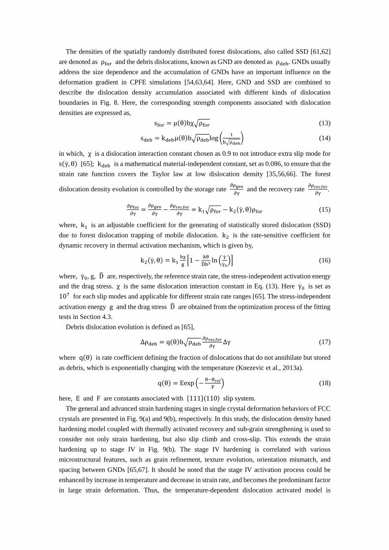
The densities of the spatially randomly distributed forest dislocations, also called SSD [61,62]
are denoted as ρfor and the debris dislocations, known as GND are denoted as ρdeb. GNDs usually
address the size dependence and the accumulation of GNDs have an important influence on the
deformation gradient in CPFE simulations [54,63,64]. Here, GND and SSD are combined to
describe the dislocation density accumulation associated with different kinds of dislocation
boundaries in Fig. 8. Here, the corresponding strength components associated with dislocation
densities are expressed as,
sfor = μ(θ)bχ√ρfor (13)
sdeb = kdebμ(θ)b√ρdeblog (1
b√ρdeb) (14)
in which, χ is a dislocation interaction constant chosen as 0.9 to not introduce extra slip mode for
s(γ̇, θ) [65]; kdeb is a mathematical material-independent constant, set as 0.086, to ensure that the
strain rate function covers the Taylor law at low dislocation density [35,56,66]. The forest
dislocation density evolution is controlled by the storage rate ∂ρgen
∂γ and the recovery rate
∂ρrec,for
∂γ.
∂ρfor
∂γ=
∂ρgen
∂γ−∂ρrec,for
∂γ= k1√ρfor − k2(γ̇, θ)ρfor (15)
where, k1 is an adjustable coefficient for the generating of statistically stored dislocation (SSD)
due to forest dislocation trapping of mobile dislocation. k2 is the rate-sensitive coefficient for
dynamic recovery in thermal activation mechanism, which is given by,
k2(γ̇, θ) = k1bχ
g[1 −
kθ
D̂b3ln (
γ̇
γ̇0)] (16)
where, γ̇0, g, D̂ are, respectively, the reference strain rate, the stress-independent activation energy
and the drag stress. χ is the same dislocation interaction constant in Eq. (13). Here γ̇0 is set as
107 for each slip modes and applicable for different strain rate ranges [65]. The stress-independent
activation energy g and the drag stress D̂ are obtained from the optimization process of the fitting
tests in Section 4.3.
Debris dislocation evolution is defined as [65],
∆ρdeb = q(θ)b√ρdeb∂ρrec,for
∂γ∆γ (17)
where q(θ) is rate coefficient defining the fraction of dislocations that do not annihilate but stored
as debris, which is exponentially changing with the temperature (Knezevic et al., 2013a).
q(θ) = Eexp(−θ−θref
F) (18)
here, E and F are constants associated with {111}⟨110⟩ slip system.
The general and advanced strain hardening stages in single crystal deformation behaviors of FCC
crystals are presented in Fig. 9(a) and 9(b), respectively. In this study, the dislocation density based
hardening model coupled with thermally activated recovery and sub-grain strengthening is used to
consider not only strain hardening, but also slip climb and cross-slip. This extends the strain
hardening up to stage IV in Fig. 9(b). The stage IV hardening is correlated with various
microstructural features, such as grain refinement, texture evolution, orientation mismatch, and
spacing between GNDs [65,67]. It should be noted that the stage IV activation process could be
enhanced by increase in temperature and decrease in strain rate, and becomes the predominant factor
in large strain deformation. Thus, the temperature-dependent dislocation activated model is

employed to model the thermo-mechanical behavior in stage IV hardening.
(a) (b)
Fig. 9 The schematic hardening process in crystalline slip systems (a) shear stress versus shear strain
in hardening process for FCC slip systems; (b) instantaneous ratio (shear stress divided by shear
strain) versus shear stress in two temperature conditions.
3.3 Temperature-consistent microscale damage
Microscopically, Hagihara et al. [16] confirmed that dislocation slip has a major influence on void
development and two voids that are close together would not coalescence preferentially if
dislocation slip is not favorably activated through them. To consider these microstructural features,
a CDM model is proposed and defined at the scale of material microstructure. The micron-scale
damage was embedded in each dislocation slip and the physics-based microstructural variable of
accumulated slip of the corresponding slip system, was determined to govern the direction and
evolution of damage variable in the single crystal. The damage evolution at elevated temperature is
characterized by the Zener-Hollomon factor.
In this study, void growth along the dislocation slip direction is the main concern and the void
state is defined by the damage variable D. In crystal plasticity, the flow stress in one slip system is
influenced by the current damage via the resolved shear stress (RSS) measure [68]
τDα =
τα
1−Dα=
T:P̅α
1−Dα, (19)
where Dα is the damage variable on the αth slip system and T is the 2nd Piola-Kirchhoff (P-K)
stress. τDα is the effective RSS acting on the damaged material at the αth slip system. The void
state is strongly coupled with stress field at each increment. When Dα = 0, the micron void does
not exist in the slip system. As soon as Dα > 0, damage initiation happens and voids begin to
nucleate and grow along the preferential direction of the αth dislocation slip. The fracture happens
when the spatial damage distribution spreads across the transverse direction of the sample. Since
the damage state is defined on each slip system, the maximum damage induced by preferential
dislocation slip dominates the void state inside one single crystal. Thus, the damage in one material
point is computed as max(Dα). The damage in this model is considered as micro-damage, since its
evolution is controlled by dislocation slip within the grain length scale of micron for both 7075 AA
and 22MnB5 BS.
The void growth and coalescence are strongly influenced by plastic anisotropy in FCC crystals,
which causes the damage anisotropy. In previous CDM models, damage anisotropy is considered
by two-rank or four-rank tensors [42,69]. In this study, preferential dislocation slip is considered as
the main effect on the direction of void growth and coalescence. The preferential directions of void
expansion in each single crystal are associated with preferential slips inside crystals. For example,
when void densities of two adjacent grains increases at their grain boundary due to intense
dislocation pile-ups, the voids begin to coalescence and generate high stress concentration near the
grain boundary. The influence of crystallographic anisotropy on void evolution patterns is discussed
in Section 5.2.
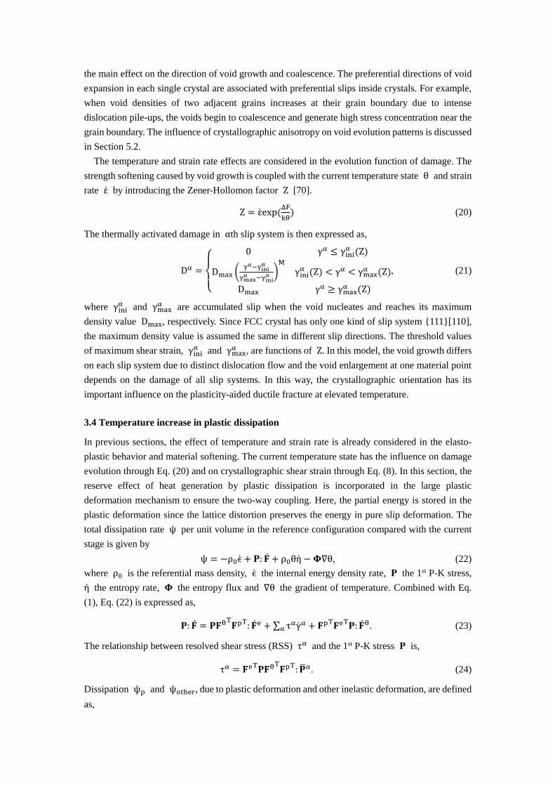
The temperature and strain rate effects are considered in the evolution function of damage. The
strength softening caused by void growth is coupled with the current temperature state θ and strain
rate ε̇ by introducing the Zener-Hollomon factor Z [70].
Z = ε̇exp (ΔF
kθ) (20)
The thermally activated damage in αth slip system is then expressed as,
Dα =
{
0 γα ≤ γini
α (Z)
Dmax (γα−γini
α
γmaxα −γini
α )M
γiniα (Z) < γα < γmax
α (Z)
Dmax γα ≥ γmaxα (Z)
, (21)
where γiniα and γmax
α are accumulated slip when the void nucleates and reaches its maximum
density value Dmax, respectively. Since FCC crystal has only one kind of slip system {111}[110],
the maximum density value is assumed the same in different slip directions. The threshold values
of maximum shear strain, γiniα and γmax
α , are functions of Z. In this model, the void growth differs
on each slip system due to distinct dislocation flow and the void enlargement at one material point
depends on the damage of all slip systems. In this way, the crystallographic orientation has its
important influence on the plasticity-aided ductile fracture at elevated temperature.
3.4 Temperature increase in plastic dissipation
In previous sections, the effect of temperature and strain rate is already considered in the elasto-
plastic behavior and material softening. The current temperature state has the influence on damage
evolution through Eq. (20) and on crystallographic shear strain through Eq. (8). In this section, the
reserve effect of heat generation by plastic dissipation is incorporated in the large plastic
deformation mechanism to ensure the two-way coupling. Here, the partial energy is stored in the
plastic deformation since the lattice distortion preserves the energy in pure slip deformation. The
total dissipation rate ψ per unit volume in the reference configuration compared with the current
stage is given by
ψ = −ρ0ϵ̇ + 𝐏: �̇� + ρ0θη̇ − 𝚽∇θ, (22)
where ρ0 is the referential mass density, ϵ̇ the internal energy density rate, 𝐏 the 1st P-K stress,
η̇ the entropy rate, 𝚽 the entropy flux and ∇θ the gradient of temperature. Combined with Eq.
(1), Eq. (22) is expressed as,
𝐏: �̇� = 𝐏𝐅θT𝐅pT: �̇�e + ∑ ταγ̇αα + 𝐅pT𝐅eT𝐏: �̇�θ. (23)
The relationship between resolved shear stress (RSS) τα and the 1st P-K stress 𝐏 is,
τα = 𝐅eT𝐏𝐅θT𝐅pT: �̅�α. (24)
Dissipation ψp and ψother, due to plastic deformation and other inelastic deformation, are defined
as,

ψp = ∑ ταγ̇αα , ψother = −ρ0ϵ̇ + ρ0θη̇ −𝚽∇θ + 𝐏𝐅θT𝐅pT: �̇�e + 𝐅pT𝐅eT𝐏: �̇�θ, (25)
respectively.
As for metal deformation process, the heat produced by elastic deformation is negligible and the
predominant temperature rise is induced by plastic deformation. Here the plastic deformation power
is used to calculate the temperature rise while ignoring the remainder of other inelastic deformation
power [71].
ρ0cθ̇ = kψp + Div(h∇ ∙ θ) − 𝚽∇θ (26)
where, c is the specific heat and h is the ratio between inelastic deformation power and the plastic
deformation power, which is in the range of 0.85 to 1.0 [72]. Here, h is chosen as 0.9. ∇ ∙ θ is the
divergence of the temperature field. The entropy flux 𝚽 is associated with the heat variation, which
is defined as,
𝚽 = ∫∆Q
θ, ∆Q = cM∆t (27)
where, dQ is the heat variation, M the mass and ∆t the time variation. The dissipation due to
thermal plastic deformation is calculated by Eq. (23) to (25) and the temperature state are updated
through Eq. (26) and (27) at the end of each time increment.
4. Computational implementation
Implicit finite element method and an advanced explicit time integration algorithm are introduced
in this section. Time step size control is applied in the algorithm.
4.1 Finite Element Method
The finite element method is applied to calculate a full-field mechanical response. Accounting for
both strain compatibility and stress equilibrium through the discretized virtual work principle, we
obtain,
(∫ 𝐁T𝐉𝐁 dVV
)∆𝐔 = 𝐑 − ∫ 𝐁T𝛔 dVV
(28)
𝐉 =∂δ𝛔
∂δ𝛆 (29)
where, 𝐁 is strain-displacement relation matrix from compatibility equations, 𝐉 is the material-
associated Jacobian matrix in terms of the tangent moduli in stress-versus-strain curves and 𝐑 is
the applied external force vector. The Jacobian matrix could be derived directly by analytically
solving d𝛔 =∂δ𝛔
∂δ𝛜d𝛜 coupled with a forward time integration method, provided by [73,74] and the
integration procedure is introduced in the following section.
In the CPFE framework, the constitutive model is leveled from micro to macro scale. At the
macro-scale, the polycrystalline response is predicted by the homogenization model, finite element
method. At the micro-scale, the thermal activation mechanism is introduced in the shear strain
activation function and the micro-damage evolution is considered within the preferential dislocation
slip. Besides, the strengthening of grain substructure is modeled by dislocation density based
hardening. The extended CPFE-CDM model has been implemented within the commercial finite
element platform called ABAQUS, where hot forming and other engineering applications are
usually simulated for nonlinear analysis of static and dynamic conditions. The constitutive formula
of crystal plasticity and micro-damage evolution are incorporated into the platform using a user

defined subroutine named UMAT. Combined with the instantaneous updated temperature state, the
microscale responses are calculated within UMAT at each time increment to analyze thermo-
mechanical behavior of AA and BS.
4.2 Time integration method with temperature and damage components
In order to calculate the Jacobian Matrix, a forward Euler time integration method is applied to
calculate the increment of shear strain on αth slip system coupled with a linear interpolation,
∆γ(α) = ∆t[(1 − χ̂)γ̇(α)(t) + χ̂γ̇(α)(t + ∆t)] (30)
Here, the interpolation control parameter χ̂ is defined as 0.35 to constrain the increasing portion of
the shear strain in a reasonable range, which consequently achieves better convergence rate in the
integration. The dislocation-density-based hardening law leads to the indirect relationship between
CRSS and shear strain rate. Consider the thermal condition and micro-damage mechanics, the shear
strain increment on each slip system is decomposed by the following formula including the effect
from temperature and micro-damage variables,
∆γ(α) = ∆t (γ̇(α)(t) + χ̂∂γ̇(α)
∂τα∆τα + χ̂
∂γ̇(α)
∂θ∆θ + χ̂
∂γ̇(α)
∂Dα∆Dα) (31)
Here, the local strain concentration, or localized plastic flow could be induced by both severe void
growth and preferential dislocation slips in the polycrystalline material. The total strain increment
of the n-th time step is then calculated as,
(∆γ)n = ∑ |(∆γ(α))n|α (32)
For an increment, the variations of forest and debris dislocation density are calculated by their
initial values at the beginning of this increment. To simply describe the incremental form of
dislocation density based hardening, the number of slip system α is omitted in the following
equations.
(∆ρfor)n = (∂ρfor
∂γ)n(∆γ)n = k1√(ρfor)n − k2(γ̇, θ)(ρfor)n (33)
(∆ρdeb)n = qbk2(γ̇, θ)√(ρdeb)n(ρfor)n(∆γ)n (34)
(ρfor)n+1 = (∆ρfor)n + (ρfor)n (35)
(ρdeb)n+1 = (∆ρdeb)n + (ρdeb)n (36)
Then at the end of this increment, CRSS is updated for the next time step using following equation,
s(γ̇, θ)n+1 = μ(θ) exp(−2πw
b) + μ(θ)HP√
b
dg+ μ(θ)bχ√(ρfor)n+1
+kdebμ(θ)b√(ρdeb)n+1ln (1
b√(ρdeb)n+1) (37)
The modified forward Euler integration method coupled with the one-step update of dislocation
density is able to separate the evolution of shear strain rate and CRSS, and the analytical solution
of Jacobian can be obtained. This integration method requires a reasonable time step to satisfy the
current stability criterion. In this study the time step is revised in each increment to obtain a better
convergence rate. Because of high nonlinearity in exponential strain rate function, the relatively
small change of CRSS in one time step could lead to high variation of shear strain rate increment.
Thus, the expected strain rate increment is controlled in each step according to ratio parameter 𝑅 =
∆𝛾𝑚𝑎𝑥𝛼 /∆𝛾𝑠 between the maximum shear strain increment ∆𝛾𝑚𝑎𝑥
𝛼 in one element and a reference
value ∆𝛾𝑠 = 1.0 × 10⁻⁴. If the ∆𝛾𝑚𝑎𝑥
𝛼 is higher than 1.25, then a lower increment ∆𝑡/𝑅 is used
to recalculate the variable at the current time step.
5. Verification and Calibration of CPFE-CDM model in RVE investigation
Representative volume element (RVE) simulations are employed to determine the thermal- and
damage-associated material parameters. The temperature of 7075 AA ranges from 300K to 773K.
In order to obtain fully transformed austenite grains of FCC crystal, the temperature of 22MnB5 BS
ranges from 873K to 1173K. The parameters related to the thermal activated mechanism are
determined by the jump tests for both materials, introduced by Hu et al. 2016 and others are fitted
by the RVE calculation compared to the thermo-mechanical curves.
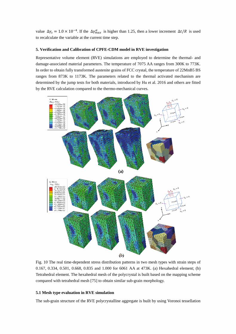
Fig. 10 The real time-dependent stress distribution patterns in two mesh types with strain steps of
0.167, 0.334, 0.501, 0.668, 0.835 and 1.000 for 6061 AA at 473K. (a) Hexahedral element; (b)
Tetrahedral element. The hexahedral mesh of the polycrystal is built based on the mapping scheme
compared with tetrahedral mesh [75] to obtain similar sub-grain morphology.
5.1 Mesh type evaluation in RVE simulation
The sub-grain structure of the RVE polycrystalline aggregate is built by using Voronoi tessellation

and realistic polycrystalline morphologies are obtained. The tetrahedral elements are usually used
to mesh the grains of the polycrystalline and they are suitable for partitioning unsmooth grain
boundaries. However, the tetrahedral elements are typically too stiff for describing the finite
deformation of large strain and may degrade accuracy in calculating the evolution of grain
morphology after severe plastic deformation [76]. As an example, hexahedral elements are
employed to calculate the RVE responses and compared with the response of tetrahedral elements
under uniaxial loading in Fig. 10. To create a similar sub-grain morphology in hexahedral mesh,
mapping method is used to obtain the polycrystalline aggregates with serrated grain boundary in
Fig. 10(a) [75]. It should be noted that the local orientation distribution are the same for these two
mesh types and no damage evolution is considered in this simulation. The material property of 6061
AA from Hu et al. 2016 is applied in the simulation.
The stress contours of two meshes are shown in Fig. 10 for a number of strain steps. For 50 sub-
grains in the RVE, 4913 and 5659 elements are used in hexahedral (C3D8) and tetrahedral (C3D4)
mesh, respectively. Full integration is used in all simulations. In relatively small strain steps, local
stress responses are similar whereas significant differences occur after total strain step is larger than
0.501. In addition, surface morphology changes severely within the hexahedral mesh in large strain
step, whereas tetrahedral mesh results in almost rectangular deformed shape. Stress distributions
show that hexahedral elements have the advantage of high precision to calculate local mechanical
response, since eight integration points are employed in hexahedral element.
(a) (b)
Fig. 11 The stress distribution of two local surface grains for both tetrahedral and hexahedral mesh
at the same spot with strain step of 0.668.
Two local surface grains from the same spots of hexahedral and tetrahedral mesh are studied in
Fig. 11 at the strain step of 0.668. Due to more degrees of freedom, the local morphology deformed
more in the hexahedral element. The local stress concentrations near the grain boundary are
observed in both mesh types and the grain interaction are captured among adjacent grains. The grain
boundary is better captured using tetrahedral mesh whereas hexahedral mesh usually causes serrated
boundary features. Thus, the tetrahedral element is generally chosen in grain boundary investigation
and interfacial modelling in CPFE analyses [77,78]. However, in another sense, the hexahedral mesh
is able to reveal surface roughening in microscale. For example, Rossiter et al., (2013) used the
hexahedral element to analyze the surface roughness correlated with the strain accommodation
capability of various grain orientations. Recently, the stabilized tetrahedral elements are developed
to overcome the volumetric locking problem in tetrahedral element and to calculate reasonable
displacement response [80,81], which can reasonably capture both grain interactions and localized

plastic deformation.
(a) (b)
Fig. 12 The RVE simulation of mesh type comparison: (a) stress versus strain curves of eight
integration points in one hexahedral element; (b) comparison of macroscopic mechanical response
between the hexahedral and tetrahedral element in averaged stress versus strain curves.
Fig. 13 The statistical Von Mises stress distribution using different RVE sizes for tetrahedral element.
Each stress bin covers the range of 50 MPa and the volume fraction is stored in each bin.
The variation of the local stress-strain behavior within a single element of the hexahedral mesh
is illustrated in Fig. 12(a) for eight integration points. In view of the significant variations within
the element, the local mechanical response fields are described more accurately using the hexahedral
mesh. Fig. 12(b) shows the overall stress-versus-strain behavior of one local grain for these two
meshes with acceptable minor variation of 5.36% (Mesh variation of overall stress-versus-strain
curve for the whole RVE is 2.54% and the variation is defined as ∫ |σhex−σtet| dεε
0
∫ |σhex| dεε
0
). Tetrahedral
discretization has more computational efficiency compared to the hexahedral mesh. The total
calculating time ratio between hexahedra and tetrahedral element is 1.672 for 50 grains aggregates
under uniaxial loading. Thus, tetrahedral mesh is employed in the calibration process in Section 5.3
to obtain overall stress-versus-strain curve that matches the experimental data. The hexahedral mesh
is used in the simulation process to ensure accurate local plastic deformation field compared with
realistic morphology in shear and tensile test in Section 6. Above all, since directional micro-
damage is incorporated in this study, the full integration hexahedral element could capture the void

growth pattern and void localization spots more accurately in the polycrystalline material with large
plastic deformation.
The local stress responses are calculated for five microscale RVEs with 30-136 grains in Fig. 13
and the tetrahedral element is used. The local stress level is divided into 22 bins with width of 50
MPa and the volume fraction is collected for each stress bin. In Fig. 13, the local stress distribution
deviates in RVEs with low grain number of 30 to 45 and it becomes stable after 58 grains RVE. This
indicates that the convergence of local stress distribution is reached for the microstructure with 58
or more grains. Compared to the result of 136 grains RVE, the relative error is defined for both
mesh types as ∑ |𝑉𝐹𝑛𝑢𝑚(𝑖) − 𝑉𝐹136(𝑖)|𝑁𝑏𝑖𝑛𝑖=1 . The direct error comparisons are shown in Tab. 1. It
explicitly shows that convergence of the local stress distribution is obtained when the number of
grains reaches 58 inside the RVE. Therefore, the 58 grains RVE is set as the preferable RVE size
for the calibration process in Section 5.3 to acquire both accuracy and efficiency.
Table 1 Error of hexahedral and tetrahedral elements in local stress distribution
Grain number in RVE 30 45 58 100
Error for Hex (%) 8.46 4.32 1.84 1.93
Error for Tet (%) 7.24 4.54 2.26 2.30
5.2 Anisotropic damage evolution study
In this section, the time-dependent evolutions of anisotropic damage are calculated for the 58 grains
RVE when the displacement conditions changes in different directions. The local damage evolution
direction varies according to the preferential dislocation flow of grains with different
crystallographic orientations. The material property of 6061 AA [53] with damage evolution is used
in the simulation. The RVE microstructure, material property and initial orientation distribution
remain the same for (a), (b) and (c) in Fig. 14.
For 6061 AA at 473K, the loading configurations applied to the RVE and the corresponding
damage contours are shown in Fig. 14. 5209 elements of C3D8 are used in the simulation with no
reduced integration. The results show that void growth and coalescence among grains are quite
sensitive to load orientation although the same uniaxial displacement control is applied in these
cases. In this model, void growth or damage evolution is mainly aided by local dislocation slip and
the direction of void expansion is strongly influenced by the preferential dislocation slip direction.
When the boundary condition changes from Fig. 14 (a) to (b) or (c), the Schmid tensor �̅�α in Eq.
(3) changes in each slip system, which leads to different preferential slip and accumulated shear
strain. Thus, distinct void growth and coalescence path occurs in each individual grain. This
microscopic phenomenon is reflected in the macroscopic test of 7075 AA in section 6.2 and the void
pattern changes with orientation and misorientation distributions.
5.3 Parameter calibration in the CPFE-CDM model
This section focuses on the calibration of temperature and damage coupled material parameters
of the extended dislocation density based crystal plasticity model for AA and BS using the
experimental data generated in this study along with those available in the literature. Specifically,
thermal tensile experiments of 300K, 673K and 773K have been employed to calibrate the crystal
plasticity model parameters for 7075 AA, whereas thermal shear experiments of 873K and 1073K

Fig. 14 Damage evolution of 6061 AA under three boundary conditions at 473K. Load steps from 1
to 5 means total strain from 0.1 to 0.5 with increment of 0.1. The length of the RVE is l and the
boundary conditions are given as:
(a) Ux = 0 at x = l, Uy = 0 at y = 0, Uz = 0 at z = l, Uy = U at y = l;
(b) Ux = 0 at x = 0, Uy = 0 at y = 0, Uz = 0 at z = 0, Uy = U at y = l;
(c) Ux = 0 at x = l, Uy = 0 at y = l, Uz = 0 at z = 0, Uz = U at z = l.
have been used to calibrate 22MnB5. The thermal activation related parameters, ΔFα, ΔVα in Eq.
(8) are calibrated by a set of jump experiments for aluminum alloy and boron steel, which is
rigorously described in our previous work [53]. The elastic modulus μ0 at initial temperature θ0,
temperature-sensivity parameter H in Eq. (12) and Hall-Petch associated parameter HP in Eq. (11)
are defined in the literature [22,52,82]. The dislocation density based physical parameters g, D̂ and
k1 in Eq. (16); E and F in Eq. (18) and damage associated paramters are calibrated by fitting the
simulation results of polycrystalline aggregates with the experimental curves using least-square fit
optimization method. The parameters of void growth are obtained as γiniα =
0.0345Z0.0510; γmaxα = 0.0376Z0.0493 and γini
α = 0.0156Z0.0353; γmaxα = 0.0175Z0.0342 for
7075 aluminum alloy and 22MnB5 steel, respectively. Dmax is calibrated as 0.78 for both materials
to improve numerical convergence upon material softening during the necking region. All the

crystal plasticity related parameters are shown in Tab. 2 and 3.
58 grains RVE with 4913 elements are used in the calibration study. The mechanical curves are
analyzed in three stages for the purpose of parameter calibration, elastic stage, strain hardening stage,
and necking stage. Each stage is assumed to be separately controlled by several corresponding
parameters, shown in Fig. 15. Parameters in each region are identified by the multi-objective
optimization using Gaussian process [83,84]. The ISIGHT optimization software combined with
ABAQUS platform is applied to perform the optimizations. The computational efficiency is
increased by calibrating parameters independently in each region to fit the experimental data,
whereas parameters in other regions are fixed. When the optimization in one stage is finished, the
obtained parameters are transferred into optimization process in the other stage. Then, the
intersections of the parameter ranges from each stage are used to fit the overall curves with a single
set of deterministic parameters. When using the three-region optimization method shown in Fig. 15,
a discontinuous tangent near the descending part is detected, which is not satisfactory for simulation
of mechanical behavior. We combine the strain hardening (B) and necking regions (C) to improve
the tangent convergence between hardening and necking behavior and continuous mechanical
behavior is obtained, shown in Fig. 16 and 17. In spite of nearly triple calibration time, by using
two-region method in optimization, the average error between CPFE and experiment decreases from
5.89% to 3.61% in 7075 AA and from 8.92% to 6.65% in 22MnB5 BS (error in each curve is defined
as ∫ |σCPFE−σexperiment| dεε
0
∫ |σexperiment| dεε
0
or ∫ |FCPFE−Fexperiment| duu
0
∫ |Fexperiment| duu
0
). The errors are shown for both methods at
different temperatures in Tab. 4. In this way, the calibration of the overall curves is improved and a
better global minimizer is obtained.
(a) (b)
Fig. 15 Schematic two-region calibration method for 7075 AA (a) and 22MnB5 BS (b) to alleviate
discontinuity between strain hardening and necking parts. The regions show different deformation
processes in RVE calculation (A: elastic stage; B: strain hardening stage; C: necking stage). σt and
εt are the engineering stress and strain for tensile experiment, respectively.
Table 2 Calibrated parameters of the crystal plasticity model for 7075 AA
μ0(GPa) H (GPa) θ0 (K) HP g D̂(MPa)
30.512 4.553 295.15 102.51 7.682 × 10⁻⁴ 75.61
k1(m−1) ε̇0(s
−1) ∆F(eV) ∆V(m3) E(MPa) F(K)
81.24 107 1.326 63.5b3 685 194

Table 3 Calibrated parameters of the crystal plasticity model for 22MnB5
μ0(GPa) H (GPa) θ0 (K) HP g D̂(MPa)
53.637 9.724 873.15 154.17 3.077 × 10⁻⁶ 126.74
k1(m−1) ε̇0(s
−1) ∆F(eV) ∆V(m3) E(MPa) F(K)
65.35 107 1.587 80.33b3 536 241
Table 4 Error comparison between two-region and three-region methods in calibration
Temperature(AA) 300K 473K 623K 673K 723K 773K
3-region error (%) 6.98 4.61 6.37 5.88 6.94 4.58
2-region error 3.02 3.65 4.25 5.28 1.75 3.69
Temperature(BS) 873K 973K 1073K 1173K
3-region error 10.41 8.56 7.46 9.28
2-region error 6.53 5.25 7.16 7.67
It is important to note that the above-mentioned process calibrates microscale material parameters
defined at each material point of polycrystalline aggregate. Whereas experiments are performed at
the macroscale and the overall behavior of the RVE characterize the damage evolution and
mechanical behavior at plastic-deformation-dominated sites in the specimen. In view of the scale
discrepancy and the large number of parameters to be calibrated using a relatively small set of
experiments, the calibration process could result in non-unique set of parameters that accurately
capture the experimental data. However, following the parameter calibration process, the previous
identified parameters are checked to ensure that they are physically meaningful.
In order to further verify the model calibration for 7075 AA, the remaining curves of uniaxial
tensile tests in Fig. 4(a) were simulated using CPFE and compared to the experimental data. All the
simulation results are compared to experimental data in Fig. 16, which show a close agreement at
different temperature conditions. The flow stress decreases when the temperature increases due to
thermal softening of the local resistance in dislocation activation.
Fig. 16 Comparison between simulation of realistic tensile specimen and experimental data under
different temperatures with stress-strain curves of 7075 AA.
The force-versus-displacement curves of shear tests at other temperatures are simulated for
22MnB5 with the calibrated parameters. During the entire loading process the shear specimen is at
temperatures higher than 693K that is the martensite phase transition temperature. Thermal

softening also occurs for 22MnB5 BS and the thermal strain increases monotonically as temperature
rises. The necking strain drop at high temperature range for 7075 AA is not observed in Fig. 17. In
the CPFE simulation with different temperature conditions for 22MnB5 BS, the entropy term
introduced previously remains negative for most of the grains. As temperature increases, the
activation energy grows lower and the local shear strain becomes higher.
Fig. 17 Comparison between simulation of realistic shear specimen and experimental data under
different temperatures with force-displacement curves of 22MnB5.
A key achievement of this work is that, using a single set of material parameters, model is able to
achieve good agreement for all mechanical responses at all temperature conditions. Specifically, the
hardening rates, damage softening, non-linear post-necking and fracture strain are simultaneously
captured. In addition, the proposed model is confirmed as a useful tool for the similar cubic metals
of FCC crystal in AA and BS at elevated temperatures. The good predictions of the tensile and shear
mechanical behavior are the results of combination of three distinct mechanisms incorporated in the
model. The thermal associated damage evolution, plastic dissipation and dislocation density based
hardening mechanism are all activated in the simulations.
In this temperature-dependent CPFE simulation, the model is able to capture the fracture strain
increase from 300K to 673K and its decrease from 673K to 773K. Necking softening occurs when
strain reaches a critical value, defined as the critical necking strain, that differs in various
temperature conditions. The maximum critical necking strain value is obtained at 673K. This
indicates that this necking strain, does not have a linear correlation with temperature.
An entropy-like term is investigated to control the temperature-associated local shear strain and
the corresponding critical necking strain. Extracted from the exponential function in Eq. (8),
(ταΔV − sαΔV − ΔF)/θ, has the same unit of entropy. At low temperature range of 300K and 473K,
the activation energy barrier is relatively high. The dislocation is hard to activate and escape from
the obstacles. The entropy term is mostly negative in RVE and the local shear strain is low. At higher
temperature of 623K and 673K, the activation energy is lower and more dislocations are nucleated
and escape from the obstacles. The entropy term is still negative for nearly all the grains and the
shear strain is higher as temperature increases. When temperature increases beyond 673K, the
activation energy is still low. The dislocation pile-ups spread over the grains and generate high
resistance for further dislocation activation in Eq. (13) and (14). The entropy term turns positive and
the shear strain becomes lower as temperature increases.

(a) (b)
Fig. 18 CPFE simulation with temperature decreasing rate of 33.6℃/s: (a) 20 grains with different
crystallographic orientations simulated in the tensile test with temperature drop. (b) Overall stress-
strain curves in the CPFE simulation compared to the experimental data at two initial temperatures
with strain rate of 1 × 10⁻³ s−1.
To cross validate the calibrated parameters in the temperature variation condition, the analyses of
22MnB5 tensile test is conducted. No damage evolution is considered in this case. In Fig. 18(a),
results of 20 random grains in the simulation with temperature decreasing rate 33.6℃/s show the
various microscopic mechanical behaviors at different crystallographic orientations of grains. The
cooling rate is assumed to be uniform in the specimen. Using this CPFE model, RVE predictions of
tensile mechanical behavior for 22MnB5 BS are performed at two initial temperatures 700℃ and
800℃ and the results agree well with the experimental data in Fig. 18(b). The nearly linear
hardening tangent in the plastic region is captured by increasing elastic moduli in Eq. (12) and slip
resistance in Eq. (9) in each grain of the RVE as temperature decreases.
6. Microstructural analyses of ductile fracture in shear and tensile test at high temperature
The calibrated CPFE-CDM models are used to perform specimen scale simulations of the shear and
tensile experiments using hexahedral elements. The microstructural variables are analyzed to
correlate with the void growth process and crucial microstructural metrics are determined on void
nucleation and growth. Microscopic physical variables, including dislocation density, orientation
mismatch and misorientation are studied in the necking region. The local dislocation density
distribution is computed which is challenging to obtain with direct experimentation.

Fig. 19 The realistic specimen and the size marking in the wire-electrode cutting of specimen. The
notch tip is treated as round to guarantee the pure shear behavior in the middle section.
Fig. 20 The initial orientation distribution of sinθ ∙ sinφ in shear specimen. The mesh in the middle
section is refined.
6.1 Simulation of shear testing of 22MnB5 at 1173K
The realistic dimension measurement of the shear specimen is shown in Fig. 19, produced by wire-
electrode cutting from a commercially produced 22MnB5 plate. The middle structure of this
specimen ensures the pure shear at this stretching direction. In order to obtain accurate damage
evolution response, small element size is specified in the middle section of the specimen. 7748
elements of C3D8 type is used in the shear simulation with full integration. The initial random grain
orientation distribution in this shear specimen is shown in Fig. 20, by pre-defined orientation value
of sinθ ∙ sinφ in pole figure of Fig. 20(b) (θ,φ,ψ are the Euler angles in Bunge’s convention).
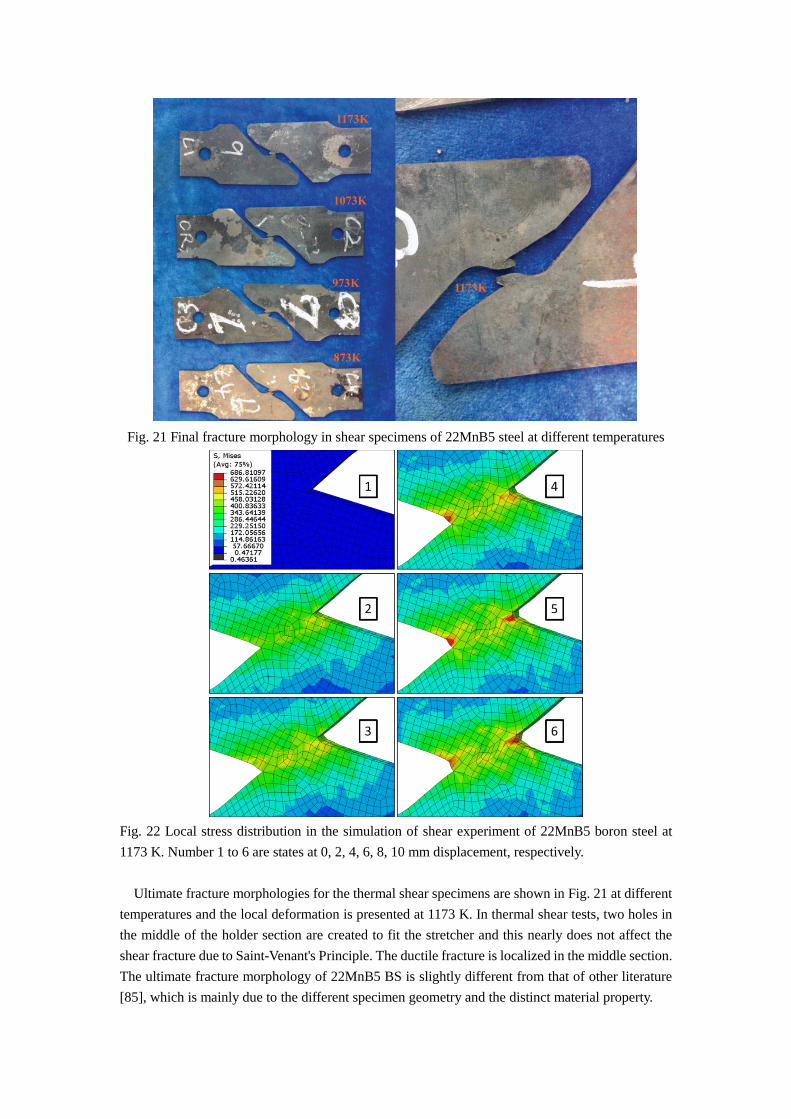
Fig. 21 Final fracture morphology in shear specimens of 22MnB5 steel at different temperatures
Fig. 22 Local stress distribution in the simulation of shear experiment of 22MnB5 boron steel at
1173 K. Number 1 to 6 are states at 0, 2, 4, 6, 8, 10 mm displacement, respectively.
Ultimate fracture morphologies for the thermal shear specimens are shown in Fig. 21 at different
temperatures and the local deformation is presented at 1173 K. In thermal shear tests, two holes in
the middle of the holder section are created to fit the stretcher and this nearly does not affect the
shear fracture due to Saint-Venant's Principle. The ductile fracture is localized in the middle section.
The ultimate fracture morphology of 22MnB5 BS is slightly different from that of other literature
[85], which is mainly due to the different specimen geometry and the distinct material property.

Fig. 23 Local strain distribution in simulation of 22MnB5 steel at 1173 K (arrow representing for
the fracture direction and circle showing the position of severe deformation). Number 1 to 6 are
states at 0, 2, 4, 6, 8, 10 mm displacement, respectively.
For shear test of 22MnB5 BS at 1173 K, simulation results of time-dependent stress and strain
distributions are presented in Fig. 22 and Fig. 23, respectively. The displacement control is applied
and the stress and strain levels in the holder section are much lower than that in the middle section.
The logarithmic strain amplitude higher than 0.5 is shown in grey color in Fig. 23, which is
compared to the void nucleation and growth patterns in Fig. 24. From the comparison, the
correlation in local strain and damage distributions suggests that the void nucleation and growth
occurs in the strain concentration sites due to localized plastic flow with the preferential dislocation
slip. These two correlated strain and damage patterns are consistent with that in the recent literatures
of ductile fracture [13,86–88].
Compared with local experimental fracture morphology in Fig. 25 at 1173K, the ultimate void
distribution results show a fine prediction. From the consistent time-dependent distribution pattern
in strain and damage evolution, it can be concluded that the void growth is promoted by local plastic
flow, in agreement with the experimental view of Pineau et al, 2016. The elements near the notch
tip region, circled in Fig. 23, experience high distortion and rotation. And the same severe plastic
deformation is shown in Fig. 25. Moreover, the arrow in Fig. 23 and the damage propagation path
in Fig. 24 show the similar ultimate shear fracture angle in Fig. 25.
In the time-dependent damage distribution in Fig. 24, the damage is initiated at the notch tips
where high stress distribution occurs at the same spots. This phenomenon is consistent with the
conclusion of Kim and Yoon, 2015 that local stress concentration was considered to trigger the
damage initiation and evolution. It appears that stress distribution can be used to describe the

damage initiation pattern. However, the correlation between damage propagation path and stress
concentration is not explicitly shown. The local stress distributions in Fig. 22(4) exhibit
concentration patterns only at two notch tips as strain step increases, whereas damage grows and
coalescences in the center of the damage region are shown in Fig. 24(6).
Fig. 24 Local damage evolution process in simulation of shear experiment of 22MnB5 boron steel
in the middle section of specimen at 1173K. Number 1 to 10 are states at 0 to 10 mm displacement
with 1 mm increment, respectively.
The damage and dislocation density are tracked throughout the shear specimen. Coupling with
dislocation density in this study, the interaction between dislocation flux and grain boundary is
explicitly shown using dislocation density distribution. To further study the correlation between
microstructural variables and damage initiation, local stress and dislocation density distributions are
investigated along the damage propagation line. In Fig. 26, the magnitudes of these two variables
are plotted in each individual element in normalized position, when local damage initiates at notch
tips of the specimen (Dα ≥ 0 at the notch tip). The maximum values of both variables are
distributed near the damage initiation spots. From this perspective, the stress and dislocation density

distributions are strongly linked to damage initiation and could be used to predict spatial damage
initiation sites.
Fig. 25 The experiment of the local middle part of the 22MnB5 specimen at 1173 K (arrow
representing for the fracture direction and the circle showing the position of severe deformation)
Fig. 26 The local Mises stress and dislocation density distributions through specific line along
necking path when local damage begins to initiate (Dα ≥ 0) at notch tip for 22MnB5 at 1173 K.
Normalized positions from 0.0 to 1.0 represent grain sites from left to right in the line.
In Fig. 26, the dislocation pile-ups and stress concentrations occur both inside each individual
grain and on the grain boundary. This implies that dislocation flow could be blocked inside grain by
substructures and dislocations pile up at grain substructure and grain boundary. Void growth induced
by preferential dislocation slip could result in both transgranular and intergranular damage. This
prediction of damage mechanism needs further experimental investigation for 22MnB5 BS at

elevated temperatures to obtain fully austenitized grains. High temperature EBSD combined with
SEM could be applied for understanding the physical damage mechanism at grain scale.
The stress distribution along normalized position is very non-uniform due to orientation mismatch
between adjacent grains. When crystallographic orientation differed severely between two grains,
the stress amplitudes separate at grain boundaries. The separation of dislocation density level is
relatively mild and the discontinuities of dislocation density level at grain boundary is smaller. This
results from different resolved shear stress level between adjacent grains with different orientations.
In addition, the dislocation penetrating flow through grain boundary results in relatively low
dislocation density jump at the grain interface.
6.2 Simulation of tensile testing of 7075 AA at 473K
Tensile numerical simulation analysis is performed to investigate damage evolution in the 7075AA
specimens subjected to tensile loading. In this simulation, 8880 elements of C3D8 type mesh are
used with full integration. The evolution of principal strain and damage distributions at 473K
throughout the specimen are presented in Fig. 27 and 28, respectively.
Consistent distributions in Fig. 27 and 28 indicates that the high damage sites follow the strain
concentration spots in the necking region, which is similar to previous phenomenon in shear test of
22MnB5 BS. This observation proves that the void initiation and growth in FCC material have a
strong correlation with local strain. Phenomenological macroscale strain-associated damage models
are employed to model the similar relationship [15,89].
Through a specific line along the damage localization zone (i.e., the necking area), local stress
and dislocation density distributions are shown in Fig. 29 when damage initiates (Dα) ≥ 0 at the
middle spot). The maximum stress and dislocation density magnitude are in the same grain and its
lattice orientation is pointed out in Fig. 29. From previous analysis in 22MnB5, stress concentration
and high dislocation pile-ups are considered as the indicator of damage initiation. The severe
orientation mismatches between adjacent lattices results in relatively high dislocation density and
high stress level near the grain boundary, which is consistent with ref. [14] that the stress
concentration results from the orientation mismatch near grain boundaries for AA. Thus, it can be
concluded that damage nucleates first near the middle spot in the specimen and the dislocation
density is considered as the necessary variable for damage activation. Above all, dislocation density
in this model is proved as the indicator for predicting local damage initiation sites in FCC material
at elevated temperatures.
Different from dislocation density distribution in 22MnB5 BS, the high dislocation density spots
in Fig. 29 tend to locate at the grain boundary and severe orientation mismatches are observed in
adjacent grain pairs. It implies that the grain boundary in 7075 AA, rather than the grain substructure,
generates the main resistance for dislocation flow. Void growth for ductile fracture is aided by the
dislocation pile-ups at the grain boundary. In this case, intergranular damage may be the
predominant local fracture mode occurring in these boundaries at elevated temperature, which is
consistent with previous experimental observation in Section 2.

Fig. 27 Strain distribution of the tensile experiment of the 7075 AA in CPFE simulation at 473 K.
Indexes from 1 to 5 means total accumulated strain value of 0.011, 0.087, 0.141, 0.161, and 0.187.
Fig. 28 Damage distribution of tensile experiment of the 7075 AA in CPFE simulation at 473 K.
Indexes from 1 to 5 means total accumulated strain value of 0.011, 0.087, 0.141, 0.161, and 0.187.

Fig. 29 The stress and dislocation density distribution through specific line along necking path when
Dα ≥ 0 over the entire specimen for 7075 AA tensile test at 473 K. Normalized positions from 0.0
to 1.0 represent grain sites from bottom to top in the line. Grey color represents the logarithmic
strain higher than 0.5 compared with damage distribution.
Fig. 30 Different fracture morphologies of 7075 and 6061 AA in thermal tensile test at 473K.
To better understand the mechanism of plasticity-aid void nucleation and growth, the relationship
between microstructural variables and void growth path (necking path) is discussed. It has been
discussed in Section 5.2 that the void growth path in this study is strongly influenced by the
microscale preferential dislocation slip. In tensile test of AA, local crystallographic orientations at

the identical locations of two same-geometry specimens are different. Accordingly, distinct damage
coalescence paths are observed that generate different fracture morphologies in Fig. 30.
Fig. 31 The necking patterns (principal strain distributions) in CPFE simulations compared to
fracture morphologies of actual specimens: (a) 6061 AA (473K); (b) 7075 AA (473K)
(a) (b)
(c) (d)
Fig. 32 Pole figure of density of orientation distribution: (a) undeformed 6061AA (b) deformed
6061AA (473K, predicted) (c) undeformed 7075AA (d) deformed 7075AA (473K, predicted)

At 473K, the same tensile test is applied for 6061 AA and 7075 AA with the wire-cut specimen
of same geometry. Two fracture morphologies are obtained including zigzag and linear fracture
modes in Fig. 31. The linear mode of 6061 AA has already been captured by the previous
phenomenological CPFE model [53]. Whereas the zigzag mode of 7075 AA is well described by
the strain localization and void growth path in the current model. In Fig. 31(a), the strain
concentration of 6061 AA is initiated at the two edges of the specimen where necking begins and
the shear band spreads across the specimen until the material separation happens across the single
shear band [53]. A different strain, or void growth pattern is observed for 7075 AA in Fig. 31(b).
Shown in Fig. 27 and 28, the void growth is first observed at both the middle and edge spots. Two
localized shear bands extend in two directions and intersect at the middle spot. Subsequently, the
void growth along the shear band and zigzag necking path is generated. The zigzag fracture mode
forms when material separate through the necking path.
In FCC materials, microstructure is determined to has important influence on the necking path
[14,90]. Various features of microstructure are discussed but the predominant factor is not
determined for forming the observed distinct necking modes. In the following study, multiple
characteristic crystallographic variables including texture evolution, orientation distribution, local
misorientation angles and Schmid factors are analyzed to determine the key microstructural effect
on the damage initiation, void growth and necking path.
For 6061 and 7075 AA, the localized dislocation behavior is determined by the crystallographic
orientation of individual grains. Here, the numerically predicted deformed pole figures in these two
microstructures are presented in Fig. 32. Due to large deformation and lattice reorientation at 473K,
volume fraction of specific grain orientation tends to increase as significant localized plastic
deformation occurs. In Fig. 32, the density of crystrallographic orientation {111}[1̅3̅1] increases
in 7075 AA after the tensile test. Whereas in study of 6061 AA, the density of estimated orientation
{111}[100] rises. However, the density rise is not significant in both materials and the relation
between grain reorientation and localized plastic flow is not explicit in this case.
In 6061 AA of FCC crystal structure, the cross section of tensile specimen contains relatively
large grains [53]. As for 7075 AA, the average grain size and the transverse geometric dimension
are about 103.4 μm and 12.5mm, respectively. This means that only about 121 grains lie through
the width length of the experimental specimen. Since the specimen width is small, limited grains
are observed through cross section for 6061AA and 7075 AA. Each individual grain has an
important effect on the local preferential dislocation flux and damage evolution. Thus, the initial
misorientation distribution have a significant influence on the local preferential dislocation
activation and it is investigated to correlate with void growth path.
In order to analyze only the effect of initial misorientation distribution on necking path observed
in Fig. 32, instead of considering the effect from material property, we utilize the identical mesh for
the two specimens and map the same orientation distribution function (ODF) of 7075 AA onto 6061
AA specimen. It should be noted that the initial specimen sizes of 6061 AA and 7075 AA are the
same. The principal strain distribution of 6061 AA in Fig. 33 is obtained in uniaxial loading at 473K,
which has the almost same zigzag fracture morphology but different strain magnitude compared
with zigzag result of 7075 AA in Fig. 30(b). The necking angles of 6061 AA with orientation
mapping are about 48o (upper) and 44o (lower), which are the similar with 49o (upper) and
45o (lower) in 7075 AA. From this analysis, it can be concluded that identical mapping of initial

ODF leads to similar dislocation nucleation sites and almost the same necking path. In addition, the
initial misorientation distribution has an important effect on localized plastic flow and the
corresponding void growth path for AA at high temperature conditions. The declining grain
reorientation at elevated temperatures in these two AA enhance the similarity of the necking path
between Fig. 31(b) and 33.
Fig. 33 Principal strain distribution in thermal tensile simulation of 6061 AA (473K) using exact
mapping of ODF from 7075 AA (same mesh geometry and specimen size).
To predict the damage initiation sites, the local mismatch and misorientation distribution are
analyzed statistically in connection with damage variable near necking paths. In the crystallographic
aspect, the orientation mismatch which causes strain heterogeneity across grain boundary is an
essential effect in predicting damage initiation sites. Since local orientation mismatches are tightly
linked to strain localization and corresponding void growth, it is worth investigating the correlation
between necking paths and misorientation angles of local grain pairs.
(a) (b)
Fig. 34 Two misorientation study for 6061 AA of line fracture and 7075AA of zigzag fracture at
473K. (a) Initial misorientation distribution in the tensile specimen; (b) Density of damage initiation
sites within 5-degree misorientation angle ranges at the total deformation ε = 0.157
The misorientation distribution patterns of 6061 AA (473K, linear necking) and 7075 AA (473K,
zigzag necking) are computed in Fig. 34(a). This proves that possible void nucleation and growth
are sensitive to local orientation mismatch, which is consistent with experimental observations [91].
On the purpose of quantifying this correlation and eliminating the effect of material property in

dislocation activation, the two misorientation distribution patterns are both calculated for 7075 AA
in the current CPFE framework.
In the CPFE analysis of 7075 AA at 473K, total deformation ε = 0.157 is specified in the strain
hardening region as the damage variable Dα > 0 occurs at multiple sites for different necking
morphologies. These sites are considered as the potential void growth sites. 347 and 325 void growth
sites are collected for zigzag and linear necking, respectively. 83.4% and 82.2% void growth sites
are obtained along the necking region, which proves that necking region has higher potential in
promoting void growth. The orientation mismatches between two adjacent sites are collected. The
angles are grouped into boxes of 5 degree and plotted for the possible void growth sites in Fig. 34(b).
Results in Fig. 34(b) shows that the high possibility to find void growth sites at the critical
misorientation angle range from 50o to 65o in the zigzag necking behavior whereas 60o to 75o
in the linear necking behavior. It implies that the dislocation pile-ups and grain interactions are more
intense at these grain pairs. Furthermore, the intergranular crack has the higher potential to occur at
the adjacent grains with these specific mismatch angles in the necking area. Too high or too low
misorientation angles are less susceptible to void growth. In both necking cases, the orientation
mismatch lower than 50 or higher than 75o are considered not possible for void growth. High
interfacial strength of the grain pairs is the main reason for these misorienation angles.
Fig. 35 For random misorientation distributions in the simulation, the schematic shear bands in the
necking region for 7075 (473K) tensile specimen: (a) ideal shear bands; (b) linear necking; (c)
zigzag necking; (d) deviated zigzag necking.
To understand the misorientation dependence for different necking modes, random misorientation
distributions are generated and misorientations in the necking regions are investigated for 7075AA
tensile tests. The schematic fracture morphologies for these simulations are presented in Fig. 35 (b),
(c) and (d), including three types, linear necking, zigzag necking and deviated zigzag necking. In
the numerical simulation, the localized ideal shear bands in Fig. 35 (a) occur in strain hardening
region. Multiple shear bands are generated by local plastic deformation. As plastic deformation
becomes severe, the shear bands begin to collapse into a localized one at the onset of necking
behavior. The collapsing necking path is mainly influenced by the dislocation pile-ups in the local
region where local mismatch angles reach the critical mismatch range. Whereas, the zigzag or
(a) (b)
(c) (d)

deviated zigzag necking would be arrested at local site when its misorientation angle exceeds the
critical mismatch angle. The phenomenon is consistent with the experimental observations that the
zigzag or linear necking behavior occurs due to localized plastic shear bands from severe dislocation
activation. And material separation or crack propagation would take place along these necking
regions through shear bands [29].
Table 5 At total deformation ε = 0.165, 0.174, maximum and minimum value of local mismatch
angles and Schmid factors at damage initiation sites in subsequent necking region using three
random misorientation distribution functions (MODF) for 7075 AA (473K).
Mismatch (degree) Schmid Factor
Value min max min max
MODF 1 53.83 67.87 0.25 0.42
MODF 2 63.42 77.31 0.37 0.41
MODF 3 58.25 74.74 0.38 0.46
For numerical verifcaition of the obtained critical orientation mismatch range for void growth, at
total deformation ε = 0.165, 0.174, the mismatch angles of possible adjacent void growth sites in
the subsequent necking region are presented for three random misorientation distribution functions
(MODFs) in Tab. 3. The results show that more than the misorientation of previous potential void
growth sites outside the necking path exceeds or near the edge of the critical range [50o, 75o]. At
these sites, the damage variables stop increasing and the void growth is arrested. When total
deformation reaches ε = 0.165, 0.174, the mismatch angles along the necking region are increased
to 85.0%, 87.1% and 84.3%, 86.8% for zigzag and linear necking path, respectively. And the angles
are mostly inside or near the critical range. The Schmid factors are also presented for the possible
void growth sites in the subsequent necking area in Tab. 3. Higher Schmid factor are correlated with
the higher local resolved shear stress and intense slip rate in the local grain. Previous study of AA
at room temperature shows that local grains oriented preferential for slip could induce damage
initiation [54,92–94]. In this study, the preferential slip with relative high Schmid factor range of
0.35 to 0.5 is observed in the damage initiation region. However, low value of 0.25 is also
collected in the adjacent sites with maximum damage Dα of 0.53. This implies that the individual
grain orientation with high Schmid factor is not necessary to trigger void growth. The void growth
under thermo-mechanical loading is more sensitive to local orientation mismatch.
7. Discussion and Conclusion
The proposed micro-damage model integrated with the effect of by local dislocation mobility on
void nucleation and growth on an experimental basis. This approach shows reasonable results for
two face-centered cubic polycrystalline materials at high temperature ranges. At quasi-static range,
shear-dominated and tensile tests are performed and no dynamic strain aging is observed here. It
appears to be impossible to perform the thermal real-time EBSD scan to study the microstructure
evolution in thermo-mechanical behavior, thus the computational investigation is implemented by
incorporating dislocation density based crystal plasticity combined the damage model. The fracture
strain and critical necking strain are captured well by this model. A crack length and void embedded
model is expected to model the void coalescence and crack initiation [95,96] and to answer the
fundamental question of dominated mode in ductile fracture [29,97].
In practical engineering application, the proposed model could be inefficient since the two-way

coupling of full temperature field and mechanical field is applied. It is worth noting that the
proposed method is mesh-dependent and critical mesh size of 1.5 times average grain size is deduced
as the previous manner [53] that reaches convergence. In the future study, homogenization methods
could be applied to simulate large-scale structural components coupling with crystal plasticity or
thermo-mechanics [98,99].
At various elevated temperatures, the shear and tensile experiments are performed for 7075 AA
and 22MnB5 BS respectively to investigate ductile fracture under high temperature conditions.
Shear-dominated and tensile specimens are designed and aligned in the horizontal direction for
thermo-mechanical experiments at quasi-static strain rates.
A crystal plasticity model CPFE-CDM is proposed which incorporates rate- and temperature
dependency, dislocation-density-based strain hardening and microscale damage evolution. The
dislocation density, temperature and damage are treated as internal variables and account for the
thermal- and damage softening in crystal plasticity framework. Reasonable prediction is obtained
between simulation and experimental results for different specimens, temperatures and materials.
Specifically, hardening rates, post-necking and fracture strain are captured for all temperature
conditions using a single calibrated set of parameters for one material. The critical thermal necking
strain is found to be influenced by an entropy-like term in the thermal activation mechanism.
Computational analysis of microstructural effects on ductile fracture is conducted at the necking
region regarding variables of crystallographic orientation and dislocation density. Dislocation
density distribution is computed and associated with damage initiation sites which indicate the
possible damage modes of transgranular and intergranular damage. Multiple fracture morphologies
in tensile test of 7075 AA is computed and related with initial orientation distribution. To predict
the potential void growth sites, critical orientation mismatch ranges are computed for both zigzag
and linear necking shapes and the void growth of the critical range is verified at high strain.
Acknowledgements
This work was funded by the Key Project of the National Natural Science Foundation of China
(No.11272075), China Postdoctoral Science Foundation (2014M561223), the Fundamental
Research Funds for the Central Universities (DUT14RC(3)032) and the financial support from the
program of China Scholarships Council (No. 201606060105).
Data Availability
The datasets generated and/or analysed during the current study are available from the
corresponding author on reasonable request.
References
[1] H. Karbasian, A.E. Tekkaya, A review on hot stamping, J. Mater. Process. Technol. 210 (2010)
2103–2118. doi:10.1016/j.jmatprotec.2010.07.019.
[2] S. Toros, F. Ozturk, I. Kacar, Review of warm forming of aluminum-magnesium alloys, J. Mater.
Process. Technol. 207 (2008) 1–12. doi:10.1016/j.jmatprotec.2008.03.057.
[3] M. Merklein, M. Wieland, M. Lechner, S. Bruschi, A. Ghiotti, Hot stamping of boron steel sheets
with tailored properties: A review, J. Mater. Process. Technol. 228 (2016) 11–24.
doi:10.1016/j.jmatprotec.2015.09.023.
[4] K. Alharbi, H. Ghadbeigi, P. Efthymiadis, M. Zanganeh, S. Celotto, R. Dashwood, C. Pinna,

Damage in dual phase steel DP1000 investigated using digital image correlation and
microstructure simulation, Model. Simul. Mater. Sci. Eng. 23 (2015). doi:10.1088/0965-
0393/23/8/085005.
[5] K.O. Pedersen, I. Westermann, T. Furu, T. Børvik, O.S. Hopperstad, Influence of microstructure
on work-hardening and ductile fracture of aluminium alloys, Mater. Des. 70 (2015) 31–44.
doi:10.1016/j.matdes.2014.12.035.
[6] A.S. Khan, S. Yu, H. Liu, Deformation induced anisotropic responses of Ti-6Al-4V alloy Part II:
A strain rate and temperature dependent anisotropic yield criterion, Int. J. Plast. 38 (2012) 1–13.
doi:10.1016/j.ijplas.2012.03.013.
[7] F. Kabirian, A.S. Khan, A. Pandey, Negative to positive strain rate sensitivity in 5xxx series
aluminum alloys: Experiment and constitutive modeling, Int. J. Plast. 55 (2014) 232–246.
doi:10.1016/j.ijplas.2013.11.001.
[8] L. Chen, G. Zhao, J. Yu, W. Zhang, Constitutive analysis of homogenized 7005 aluminum alloy
at evaluated temperature for extrusion process, Mater. Des. 66 (2015) 129–136.
doi:10.1016/j.matdes.2014.10.045.
[9] L. Chen, J. Chen, R.A. Lebensohn, Y.Z. Ji, T.W. Heo, S. Bhattacharyya, K. Chang, S. Mathaudhu,
Z.K. Liu, L.Q. Chen, An integrated fast Fourier transform-based phase-field and crystal plasticity
approach to model recrystallization of three dimensional polycrystals, Comput. Methods Appl.
Mech. Eng. 285 (2015) 829–848. doi:10.1016/j.cma.2014.12.007.
[10] T.K. Eller, L. Greve, M.T. Andres, M. Medricky, A. Hatscher, V.T. Meinders, A.H. Van Den
Boogaard, Plasticity and fracture modeling of quench-hardenable boron steel with tailored
properties, J. Mater. Process. Technol. 214 (2014) 1211–1227.
doi:10.1016/j.jmatprotec.2013.12.015.
[11] D. Zhao, Y. Zhu, L. Ying, P. Hu, Y. Chang, W. Zhang, Numerical simulation of deformation
behavior of 22MnB5 boron steel at elevated temperatures and experimental verification, Acta
Mech. Solida Sin. 27 (2014) 579–587. doi:10.1016/S0894-9166(15)60003-9.
[12] J. Zhou, B. Wang, M. Huang, Two constitutive descriptions of boron steel 22MnB5 at high
temperature, Mater. Des. 63 (2014) 738–748. doi:10.1016/j.matdes.2014.07.008.
[13] C.C. Tasan, J.P.M. Hoefnagels, M. Diehl, D. Yan, F. Roters, D. Raabe, Strain localization and
damage in dual phase steels investigated by coupled in-situ deformation experiments and crystal
plasticity simulations, Int. J. Plast. 63 (2014) 198–210. doi:10.1016/j.ijplas.2014.06.004.
[14] J.B. Kim, J.W. Yoon, Necking behavior of AA 6022-T4 based on the crystal plasticity and
damage models, Int. J. Plast. 73 (2015) 3–23. doi:10.1016/j.ijplas.2015.06.013.
[15] J.Q. Tan, M. Zhan, S. Liu, T. Huang, J. Guo, H. Yang, A modified Johnson-Cook model for
tensile flow behaviors of 7050-T7451 aluminum alloy at high strain rates, Mater. Sci. Eng. A.
631 (2015) 214–219. doi:10.1016/j.msea.2015.02.010.
[16] K. Hagihara, T. Mayama, M. Honnami, M. Yamasaki, H. Izuno, T. Okamoto, T. Ohashi, T.
Nakano, Y. Kawamura, Orientation dependence of the deformation kink band formation behavior
in Zn single crystal, Int. J. Plast. 77 (2016) 174–191. doi:10.1016/j.ijplas.2015.10.005.
[17] B. Klusemann, G. Fischer, T. Böhlke, B. Svendsen, Thermomechanical characterization of
Portevin-Le Châtelier bands in AlMg3 (AA5754) and modeling based on a modified Estrin-
McCormick approach, Int. J. Plast. 67 (2015) 192–216. doi:10.1016/j.ijplas.2014.10.011.
[18] H. Abdolvand, M. Majkut, J. Oddershede, S. Schmidt, U. Lienert, B.J. Diak, P.J. Withers, M.R.
Daymond, On the deformation twinning of Mg AZ31B: A three-dimensional synchrotron X-ray

diffraction experiment and crystal plasticity finite element model, Int. J. Plast. 70 (2015) 77–97.
doi:10.1016/j.ijplas.2015.03.001.
[19] W. Muhammad, B.A. P., J. Kang, M.R. K., I. Kaan, Experimental and numerical investigation of
texture evolution and the effects of intragranular backstresses in aluminum alloys subjected to
large strain cyclic simple shear, Int. J. Plast. Accepted (2016) 1–27.
doi:10.1016/j.ijplas.2016.11.003.
[20] S.H. Choi, D.W. Kim, B.S. Seong, A.D. Rollett, 3-D simulation of spatial stress distribution in
an AZ31 Mg alloy sheet under in-plane compression, Int. J. Plast. 27 (2011) 1702–1720.
doi:10.1016/j.ijplas.2011.05.014.
[21] C. Keller, E. Hug, A.M. Habraken, L. Duchêne, Effect of stress path on the miniaturization size
effect for nickel polycrystals, Int. J. Plast. 64 (2015) 26–39. doi:10.1016/j.ijplas.2014.07.001.
[22] P. Hu, D. Shi, L. Ying, G. Shen, W. Liu, The finite element analysis of ductile damage during hot
stamping of 22MnB5 steel, Mater. Des. 69 (2015) 141–152. doi:10.1016/j.matdes.2014.12.044.
[23] J. Zhang, Y. Liu, J. Liu, Y. Yu, S. Wang, The effect of Gd element and solution treatment on the
microstructure of AZ31 magnesium alloy and its kinetic model, J. Alloys Compd. 663 (2016)
610–616. doi:10.1016/j.jallcom.2015.12.133.
[24] X. Zhang, C. Oskay, Polycrystal plasticity modeling of nickel-based superalloy in 617 subjected
to cyclic loading at high temperature, Model. Simul. Mater. Sci. Eng. 24 (2016).
doi:10.1088/0965-0393/24/5/055009.
[25] V.T. Phan, X. Zhang, Y. Li, C. Oskay, Microscale modeling of creep deformation and rupture in
Nickel-based superalloy IN 617 at high temperature, Mech. Mater. 114 (2017) 215–227.
doi:10.1016/j.mechmat.2017.08.008.
[26] P. Eisenlohr, M. Diehl, R.A. Lebensohn, F. Roters, A spectral method solution to crystal elasto-
viscoplasticity at finite strains, Int. J. Plast. 46 (2013) 37–53. doi:10.1016/j.ijplas.2012.09.012.
[27] R.A. Lebensohn, A.K. Kanjarla, P. Eisenlohr, An elasto-viscoplastic formulation based on fast
Fourier transforms for the prediction of micromechanical fields in polycrystalline materials, Int.
J. Plast. 32–33 (2012) 59–69. doi:10.1016/j.ijplas.2011.12.005.
[28] D.C. Ahn, P. Sofronis, R. Minich, On the micromechanics of void growth by prismatic-
dislocation loop emission, J. Mech. Phys. Solids. 54 (2006) 735–755.
doi:10.1016/j.jmps.2005.10.011.
[29] A. Pineau, A.A. Benzerga, T. Pardoen, Failure of metals I: Brittle and ductile fracture, Acta Mater.
107 (2016) 424–483. doi:10.1016/j.actamat.2015.12.034.
[30] M. Knezevic, R.J. McCabe, R.A. Lebensohn, C.N. Tomé, C. Liu, M.L. Lovato, B. Mihaila,
Integration of self-consistent polycrystal plasticity with dislocation density based hardening laws
within an implicit finite element framework: Application to low-symmetry metals, J. Mech. Phys.
Solids. 61 (2013) 2034–2046. doi:10.1016/j.jmps.2013.05.005.
[31] R.J. McCabe, L. Capolungo, P.E. Marshall, C.M. Cady, C.N. Tomé, Deformation of wrought
uranium: Experiments and modeling, Acta Mater. 58 (2010) 5447–5459.
doi:10.1016/j.actamat.2010.06.021.
[32] K. Kitayama, C.N. Tomé, E.F. Rauch, J.J. Gracio, F. Barlat, A crystallographic dislocation model
for describing hardening of polycrystals during strain path changes. Application to low carbon
steels, Int. J. Plast. 46 (2013) 54–69. doi:10.1016/j.ijplas.2012.09.004.
[33] M. Zecevic, M. Knezevic, A dislocation density based elasto-plastic self-consistent model for
the prediction of cyclic deformation: Application to AA6022-T4, Int. J. Plast. 72 (2015) 200–

217. doi:10.1016/j.ijplas.2015.05.018.
[34] M. Knezevic, J. Crapps, I.J. Beyerlein, D.R. Coughlin, K.D. Clarke, R.J. McCabe, Anisotropic
modeling of structural components using embedded crystal plasticity constructive laws within
finite elements, Int. J. Mech. Sci. 105 (2016) 227–238. doi:10.1016/j.ijmecsci.2015.11.021.
[35] M. Knezevic, R.J. McCabe, C.N. Tomé, R.A. Lebensohn, S.R. Chen, C.M. Cady, G.T. Gray, B.
Mihaila, Modeling mechanical response and texture evolution of alpha-uranium as a function of
strain rate and temperature using polycrystal plasticity, Int. J. Plast. 43 (2013) 70–84.
doi:10.1016/j.ijplas.2012.10.011.
[36] C. Reuber, P. Eisenlohr, F. Roters, D. Raabe, Dislocation density distribution around an indent in
single-crystalline nickel: Comparing nonlocal crystal plasticity finite-element predictions with
experiments, Acta Mater. 71 (2014) 333–348. doi:10.1016/j.actamat.2014.03.012.
[37] J.W. Wilkerson, K.T. Ramesh, A dynamic void growth model governed by dislocation kinetics,
J. Mech. Phys. Solids. 70 (2014) 262–280. doi:10.1016/j.jmps.2014.05.018.
[38] G.D. Nguyen, A.M. Korsunsky, J.P.H. Belnoue, A nonlocal coupled damage-plasticity model for
the analysis of ductile failure, Int. J. Plast. 64 (2015) 56–75. doi:10.1016/j.ijplas.2014.08.001.
[39] A. Mbiakop, A. Constantinescu, K. Danas, An analytical model for porous single crystals with
ellipsoidal voids, J. Mech. Phys. Solids. 84 (2015) 436–467. doi:10.1016/j.jmps.2015.07.011.
[40] M. Basirat, T. Shrestha, G.P. Potirniche, I. Charit, K. Rink, A study of the creep behavior of
modified 9Cr-1Mo steel using continuum-damage modeling, Int. J. Plast. 37 (2012) 95–107.
doi:10.1016/j.ijplas.2012.04.004.
[41] S. Kruch, J.L. Chaboche, Multi-scale analysis in elasto-viscoplasticity coupled with damage, in:
Int. J. Plast., 2011: pp. 2026–2039. doi:10.1016/j.ijplas.2011.03.007.
[42] L. Malcher, E.N. Mamiya, An improved damage evolution law based on continuum damage
mechanics and its dependence on both stress triaxiality and the third invariant, Int. J. Plast. 56
(2014) 232–261. doi:10.1016/j.ijplas.2014.01.002.
[43] A. Shojaei, G.Z. Voyiadjis, P.J. Tan, Viscoplastic constitutive theory for brittle to ductile damage
in polycrystalline materials under dynamic loading, Int. J. Plast. 48 (2013) 125–151.
doi:10.1016/j.ijplas.2013.02.009.
[44] Y. Alinaghian, M. Asadi, A. Weck, Effect of pre-strain and work hardening rate on void growth
and coalescence in AA5052, Int. J. Plast. 53 (2014) 193–205. doi:10.1016/j.ijplas.2013.08.007.
[45] M. Brünig, S. Gerke, V. Hagenbrock, Micro-mechanical studies on the effect of the stress
triaxiality and the Lode parameter on ductile damage, Int. J. Plast. 50 (2013) 49–65.
doi:10.1016/j.ijplas.2013.03.012.
[46] A. Kami, B.M. Dariani, A. Sadough Vanini, D.S. Comsa, D. Banabic, Numerical determination
of the forming limit curves of anisotropic sheet metals using GTN damage model, J. Mater.
Process. Technol. 216 (2015) 472–483. doi:10.1016/j.jmatprotec.2014.10.017.
[47] D. Paquet, S. Ghosh, Microstructural effects on ductile fracture in heterogeneous materials. Part
I: Sensitivity analysis with LE-VCFEM, Eng. Fract. Mech. 78 (2011) 205–225.
doi:10.1016/j.engfracmech.2010.07.009.
[48] A. Hosokawa, H. Toda, R. Batres, H. Li, O. Kuwazuru, M. Kobayashi, H. Yakita, Ductile fracture
via hydrogen pore mechanism in an aluminum alloy; quantitative microstructural analysis and
image-based finite element analysis, Mater. Sci. Eng. A. 671 (2016) 96–106.
doi:10.1016/j.msea.2016.06.037.
[49] T.W.J. de Geus, R.H.J. Peerlings, M.G.D. Geers, Microstructural modeling of ductile fracture

initiation in multi-phase materials, Eng. Fract. Mech. 147 (2015) 318–330.
doi:10.1016/j.engfracmech.2015.04.010.
[50] F. Hannard, T. Pardoen, E. Maire, C. Le Bourlot, R. Mokso, A. Simar, Characterization and
micromechanical modelling of microstructural heterogeneity effects on ductile fracture of 6xxx
aluminium alloys, Acta Mater. 103 (2016) 558–572. doi:10.1016/j.actamat.2015.10.008.
[51] W. Huang, Q. Huo, Z. Fang, Z. Xiao, Y. Yin, Z. Tan, X. Yang, Damage analysis of hot-rolled
AZ31 Mg alloy sheet during uniaxial tensile testing under different loading directions, Mater.
Sci. Eng. A. 710 (2018) 289–299. doi:10.1016/j.msea.2017.10.108.
[52] M.H. Shaeri, M. Shaeri, M.T. Salehi, S.H. Seyyedein, F. Djavanrodi, Microstructure and texture
evolution of Al-7075 alloy processed by equal channel angular pressing, Trans. Nonferrous Met.
Soc. China. 25 (2015) 1367–1375. doi:10.1016/S1003-6326(15)63735-9.
[53] P. Hu, Y. Liu, Y. Zhu, L. Ying, Crystal plasticity extended models based on thermal mechanism
and damage functions: Application to multiscale modeling of aluminum alloy tensile behavior,
Int. J. Plast. 86 (2016) 1–25. doi:10.1016/j.ijplas.2016.07.001.
[54] F.P.E. Dunne, D. Rugg, A. Walker, Lengthscale-dependent, elastically anisotropic, physically-
based hcp crystal plasticity: Application to cold-dwell fatigue in Ti alloys, Int. J. Plast. 23 (2007)
1061–1083. doi:10.1016/j.ijplas.2006.10.013.
[55] T. Zhang, D.M. Collins, F.P.E. Dunne, B.A. Shollock, Crystal plasticity and high-resolution
electron backscatter diffraction analysis of full-field polycrystal Ni superalloy strains and
rotations under thermal loading, Acta Mater. 80 (2014) 25–38.
doi:10.1016/j.actamat.2014.07.036.
[56] M. Ardeljan, I.J. Beyerlein, M. Knezevic, A dislocation density based crystal plasticity finite
element model: Application to a two-phase polycrystalline HCP/BCC composites, J. Mech. Phys.
Solids. 66 (2014) 16–31. doi:10.1016/j.jmps.2014.01.006.
[57] N. Ono, R. Nowak, S. Miura, Effect of deformation temperature on Hall-Petch relationship
registered for polycrystalline magnesium, Mater. Lett. 58 (2004) 39–43. doi:10.1016/S0167-
577X(03)00410-5.
[58] E.R.F. Lqyd, A.L. Kleinman, 5p K Iyengar, G. Venkataraman, P.R. Vijayarag-Havan, A.P. Roy,
Y.P. Varshni, Temperature Dependence of the Elastic Constants, P. R. Antoniewicz L. Kleinmann
Phys. Rev. Proc. Roy. Soc. Phys. Rev. ~42 1 J. L. Falicov, Proc. Roy. Soc. Phys. Rev. B. 215
(1962) 40–215. doi:10.1103/PhysRevB.2.3952.
[59] S.R. Chen, G.T. Gray, Constitutive behavior of tantalum and tantalum-tungsten alloys, Metall.
Mater. Trans. A. 27 (1996) 2994–3006. doi:10.1007/BF02663849.
[60] D.M. Goto, R.K. Garrett, J.F. Bingert, S.R. Chen, G.T. Gray, The mechanical threshold stress
constitutive-strength model description of HY-100 steel, Metall. Mater. Trans. A. 31 (2000)
1985–1996. doi:10.1007/s11661-000-0226-8.
[61] B. Svendsen, S. Bargmann, On the continuum thermodynamic rate variational formulation of
models for extended crystal plasticity at large deformation, J. Mech. Phys. Solids. 58 (2010)
1253–1271. doi:10.1016/j.jmps.2010.06.005.
[62] S. Ghosh, A. Shahba, X. Tu, E.L. Huskins, B.E. Schuster, Crystal plasticity FE modeling of Ti
alloys for a range of strain-rates. Part II: Image-based model with experimental validation, Int. J.
Plast. 87 (2016) 48–68. doi:10.1016/j.ijplas.2016.09.003.
[63] P. Lin, Z. Liu, Z. Zhuang, Numerical study of the size-dependent deformation morphology in
micropillar compressions by a dislocation-based crystal plasticity mode, Int. J. Plast. 87 (2016)

32–47. doi:10.1016/j.ijplas.2016.09.001.
[64] A. Khosravani, J. Scott, M.P. Miles, D. Fullwood, B.L. Adams, R.K. Mishra, Twinning in
magnesium alloy AZ31B under different strain paths at moderately elevated temperatures, Int. J.
Plast. 45 (2013) 160–173. doi:10.1016/j.ijplas.2013.01.009.
[65] I.J. Beyerlein, C.N. Tomé, A dislocation-based constitutive law for pure Zr including temperature
effects, Int. J. Plast. 24 (2008) 867–895. doi:10.1016/j.ijplas.2007.07.017.
[66] L. Capolungo, I.J. Beyerlein, G.C. Kaschner, C.N. Tomé, On the interaction between slip
dislocations and twins in HCP Zr, Mater. Sci. Eng. A. 513–514 (2009) 42–51.
doi:10.1016/j.msea.2009.01.035.
[67] D. Kuhlmann-Wilsdorf, The theory of dislocation-based crystal plasticity, Philos. Mag. A Phys.
Condens. Matter, Struct. Defects Mech. Prop. 79 (1999) 955–1008.
doi:10.1080/01418619908210342.
[68] C. Jean, Lemaitre; Jean-Louis, ASPECT PHENOMENOLOGIQUE DE LA RUPTURE PAR
ENDOMMAGEMENT, J. Mécanique Appliquée. 2 (1978) 317–65.
http://worldcat.org/issn/03990842.
[69] M. Mengoni, J.P. Ponthot, A generic anisotropic continuum damage model integration scheme
adaptable to both ductile damage and biological damage-like situations, Int. J. Plast. 66 (2015)
46–70. doi:10.1016/j.ijplas.2014.04.005.
[70] X. min ZHANG, W. dong ZENG, Y. SHU, Y. gang ZHOU, Y. qing ZHAO, H. WU, H. qing YU,
Fracture criterion for predicting surface cracking of Ti40 alloy in hot forming processes, Trans.
Nonferrous Met. Soc. China (English Ed. 19 (2009) 267–271. doi:10.1016/S1003-
6326(08)60263-0.
[71] P. Rosakis, A.J. Rosakis, G. Ravichandran, J. Hodowany, Thermodynamic internal variable
model for the partition of plastic work into heat and stored energy in metals, J. Mech. Phys.
Solids. 48 (2000) 581–607. doi:10.1016/S0022-5096(99)00048-4.
[72] L. Anand, M.E. Gurtin, Thermal effects in the superelasticity of crystalline shape-memory
materials, J. Mech. Phys. Solids. 51 (2003) 1015–1058. doi:10.1016/S0022-5096(03)00017-6.
[73] Y. Huang, A user-material subroutine incorporating single crystal plasticity in the ABAQUS
finite element program.pdf, (1991).
http://www.columbia.edu/~jk2079/Kysar_Research_Laboratory/Single_Crystal_UMAT.html.
[74] E.B. Marin, P.R. Dawson, Elastoplastic finite element analyses of metal deformations using
polycrystal constitutive models, Comput. Methods Appl. Mech. Eng. 165 (1998) 23–41.
doi:10.1016/S0045-7825(98)00033-4.
[75] R. Quey, P.R. Dawson, F. Barbe, Large-scale 3D random polycrystals for the finite element
method: Generation, meshing and remeshing, Comput. Methods Appl. Mech. Eng. 200 (2011)
1729–1745. doi:10.1016/j.cma.2011.01.002.
[76] I. Simonovski, L. Cizelj, N. Jakšić, The influence of finite element meshes on the results of a
spatial polycrystalline aggregate model, Nucl. Eng. Des. 241 (2011) 1184–1190.
doi:10.1016/j.nucengdes.2010.05.063.
[77] J.R. Mayeur, I.J. Beyerlein, C.A. Bronkhorst, H.M. Mourad, Incorporating interface affected
zones into crystal plasticity, Int. J. Plast. 65 (2015) 206–225. doi:10.1016/j.ijplas.2014.08.013.
[78] I. Benedetti, M.H. Aliabadi, A three-dimensional cohesive-frictional grain-boundary
micromechanical model for intergranular degradation and failure in polycrystalline materials,
Comput. Methods Appl. Mech. Eng. 265 (2013) 36–62. doi:10.1016/j.cma.2013.05.023.

[79] J. Rossiter, A. Brahme, K. Inal, R. Mishra, Numerical analyses of surface roughness during
bending of FCC single crystals and polycrystals, Int. J. Plast. 46 (2013) 82–93.
doi:10.1016/j.ijplas.2013.01.016.
[80] A. Masud, T.J. Truster, A framework for residual-based stabilization of incompressible finite
elasticity: Stabilized formulations and F methods for linear triangles and tetrahedra, Comput.
Methods Appl. Mech. Eng. 267 (2013) 359–399. doi:10.1016/j.cma.2013.08.010.
[81] J. Cheng, A. Shahba, S. Ghosh, Stabilized tetrahedral elements for crystal plasticity finite
element analysis overcoming volumetric locking, Comput. Mech. 57 (2016) 733–753.
doi:10.1007/s00466-016-1258-2.
[82] R.W. Armstrong, 60 Years of Hall-Petch: Past to Present Nano-Scale Connections, Mater. Trans.
55 (2014) 2–12. doi:10.2320/matertrans.MA201302.
[83] V. Picheny, Multiobjective optimization using Gaussian process emulators via stepwise
uncertainty reduction, Stat. Comput. 25 (2015) 1265–1280. doi:10.1007/s11222-014-9477-x.
[84] M. Seeger, Gaussian processes for machine learning, Int. J. Neural Syst. 14 (2004) 69–106.
doi:10.1142/S0129065704001899.
[85] Y. Bao, T. Wierzbicki, On fracture locus in the equivalent strain and stress triaxiality space, Int.
J. Mech. Sci. 46 (2004) 81–98. doi:10.1016/j.ijmecsci.2004.02.006.
[86] J.B. Kim, J.W. Yoon, Analysis of the Necking Behaviors with the Crystal Plasticity Model Using
3-Dimensional Shaped Grains, Adv. Mater. Res. 684 (2013) 357–361.
doi:10.4028/www.scientific.net/AMR.684.357.
[87] M. Kashfuddoja, M. Ramji, Assessment of local strain field in adhesive layer of an
unsymmetrically repaired CFRP panel using digital image correlation, Int. J. Adhes. Adhes. 57
(2015) 57–69. doi:10.1016/j.ijadhadh.2014.10.005.
[88] T.F. Morgeneyer, T. Taillandier-Thomas, A. Buljac, L. Helfen, F. Hild, On strain and damage
interactions during tearing: 3D in situ measurements and simulations for a ductile alloy
(AA2139-T3), J. Mech. Phys. Solids. 96 (2016) 550–571. doi:10.1016/j.jmps.2016.07.012.
[89] C. Oskay, M. Haney, Computational modeling of titanium structures subjected to thermo-chemo-
mechanical environment, Int. J. Solids Struct. 47 (2010) 3341–3351.
doi:10.1016/j.ijsolstr.2010.08.014.
[90] C. Nikhare, P.D. Hodgson, M. Weiss, Necking and fracture of advanced high strength steels,
Mater. Sci. Eng. A. 528 (2011) 3010–3013. doi:10.1016/j.msea.2010.12.098.
[91] N. Bonora, D. Gentile, A. Pirondi, G. Newaz, Ductile damage evolution under triaxial state of
stress: Theory and experiments, Int. J. Plast. 21 (2005) 981–1007.
doi:10.1016/j.ijplas.2004.06.003.
[92] H. Proudhon, J. Li, F. Wang, A. Roos, V. Chiaruttini, S. Forest, 3D simulation of short fatigue
crack propagation by finite element crystal plasticity and remeshing, in: Int. J. Fatigue, 2016: pp.
238–246. doi:10.1016/j.ijfatigue.2015.05.022.
[93] S.J. Marcadet, D. Mohr, Effect of compression-tension loading reversal on the strain to fracture
of dual phase steel sheets, Int. J. Plast. 72 (2015) 21–43. doi:10.1016/j.ijplas.2015.05.002.
[94] Z. Zheng, D.S. Balint, F.P.E. Dunne, Discrete dislocation and crystal plasticity analyses of load
shedding in polycrystalline titanium alloys, Int. J. Plast. 87 (2016) 15–31.
doi:10.1016/j.ijplas.2016.08.009.
[95] M. Diehl, M. Wicke, P. Shanthraj, F. Roters, A. Brueckner-Foit, D. Raabe, Coupled Crystal
Plasticity–Phase Field Fracture Simulation Study on Damage Evolution Around a Void: Pore

Shape Versus Crystallographic Orientation, JOM. 69 (2017) 872–878. doi:10.1007/s11837-017-
2308-8.
[96] A. Patra, D.L. McDowell, A void nucleation and growth based damage framework to model
failure initiation ahead of a sharp notch in irradiated bcc materials, J. Mech. Phys. Solids. 74
(2015) 111–135. doi:10.1016/j.jmps.2014.10.006.
[97] C. Teko lu, J.W. Hutchinson, T. Pardoen, On localization and void coalescence as a precursor to
ductile fracture, Philos. Trans. R. Soc. A Math. Phys. Eng. Sci. 373 (2015) 20140121–20140121.
doi:10.1098/rsta.2014.0121.
[98] S. Zhang, C. Oskay, Reduced order variational multiscale enrichment method for thermo-
mechanical problems, Comput. Mech. 59 (2017) 887–907. doi:10.1007/s00466-017-1380-9.
[99] X. Zhang, C. Oskay, Eigenstrain based reduced order homogenization for polycrystalline
materials, Comput. Methods Appl. Mech. Eng. 297 (2015) 408–436.
doi:10.1016/j.cma.2015.09.006.