experimental determination of the relationship between
TRANSCRIPT

. PqPER hWMBER: USA-324-1 ‘ 8 7
SfiNr bb b “1% oq 1 1 c4 sflm--7r-o+/ IC eofi F-4 g o 620- -
Experimental Determination of the Relationship Between Permeability and
Microfracture-Induced Damage in Bedded Salt
T. W. Pfeifle,’ N. S. Brodsky? and D. E. Munson’ ‘ ._.^. *.*% . . ”, .1- ..- -
‘RE/SPEC Inc. P.O. Box 725, Rapid City, SD USA 57709
2Sandia National Laboratories P.O. Box 5800, qbuquerque, NM USA 87185
\ ABSTRACT
The development of deep underground structures (e.g., shafts, mines, storage and disposal caverns) Sigruscantly alters the stress state in the rock near the structure or opening. The effect of such an opening is to concentrate the far-field stress near the free surface. For soft rock such as salt, the concentrating effect of the opening induces deviatoric stresses in the salt that may be large enough to initiate microcracks which then propagate with k. The volume of rock susceptible to damage by microfracturing is often referred to as the disturbed rock zone and, by its nature, is expected to exhibit high permeability relative to that of the native, far-field rock This paper presents laboratory data that characterize Microfracture-induced damage and the e 5 c t this damage has on permeability for bedded salt from the Waste Isolation Pilot Plant located in southeastern New Mexico. Damage is induced in the salt through a series of tertiary creep experimnts and quantified in terms of dilatant volumetric strain. The permeability of damaged specimens is then measured using nitrogen gas as the permeant. The range in damage investigated included dilatant volumetric strains &om less than 0.03 percent to nearly 4.0 percent. Permeability values corresponding to these d&ge levels ranged from 1 x m2 to 1 x lo-’’ m2. Two simple models were fitted to the data for use in predicting permeability from dilatant volumetric strain.
KEYWORDS 19980423 132 Salt, damage, dilatant volumetric strain, permeability, nuclear waste, WTPP
INTRODUCTION
The U. S. Department of Energy has developed the Waste Isolation Pilot Plant (WIPP) in southeastern New Mexico as a research and development facility for the purpose of demonstrating the safe management, storage, and disposal of radioactive transuranic waste. The WIPP is expected to house both contact-handled and remotely-handled wastes generated by defense programs of the U. S. Government. The underground
DISCLAIMER
This report was prepared as an account of work sponsored by an agency of the United States Government. Neither the United States Government nor any agency thereof, nor any of their employees, makes any warranty, express or implied, or assumes any legal liability or responsibility for the accuracy, completeness, or use- fulness of any information, apparatus, product, or process disclosed, or represents that its use would not infringe privately owned rights. Reference herein to any spe- cific commercial product, process, or service by trade name, trademark, manufac- turer, or otherwise does not necessarily constitute or imply its endorsement, recom- mendation, or favoring by the United States Government or any agency thereof. The views and opinions of authors expressed herein do not necessarily state or reflect those of the United States Government or any agency thereof.

~ , T . workings of the W P are located in the bedded salt of the Salad0 Formation at a depth of about 660 meters
~
and access is provided by four vedcal shafts having diameters that vary from 3 meters to 6 meters.
Deviatoric stress states develop in the salt near each WIPP opening immediately after excavation because of the stress concentrating effect of the opening itself. The magnitudes of these deviatonc stresses are highest near,the opening, but decrease in proportion to the reciprocal of the squared radial distance from the opening. Microcrack initiation and propagation are assumed to have occurred in the salt near the openings because of the relatively large deviatoric stresses. Since microcrack density and size depend on the magnitude and duration of the induced deviatoric stress, damage is expected to be more pronounced near each opening. At SO^ distance away from the opening, microfracture-induced damage is not expected because the deviatoric stresses in the salt are relatively low. The volume of damaged salt near the WIPP openings is referred to as the disturbed rock zone ( D E ) and is known to exhibit higher permeability than the native undamaged salt (e.g., Stormont, 1990; Dale and Hurtado, 1996).
During closure of the WIPP, the vertical shafts that provide access to the underground workings will be sealed to limit the release of hazardous waste from the repository and to limit groundwater flow into the facility (Sandia National Laboratories, 1996). As such, the seals placed in the shafts must be designed to have low permeability and must also account for the potential of fluid flow through the DRZ. The design must consider the mechanisms that cause damage in salt, the radial extent of the D E , and the changes in Permeability related to this damage. This paper presents laboratory data collected under a formal Quality Assurance Program that characterize both the microfracturing process that occurs in WIPP salt and the relationship between this microfracture-induced damage and permeability.
TECHNICAL APPROACH
Two laboratory-scale experiments were conducted at RE/SPEC Inc. on WIPP salt specimens to determine the effect of microfracture-induced damage on gas permeability. Damage was quanti€ied in terms of dilatant volumetric strain. The salt specimens used in the experiments were especially prepared from clean native salt cores recovered from the WlPP workings and were right-circular solid cylinders. The nominal length and diameter of each specimen was 200 millimeters and 100 millimeters, respectively.
In the first experiment, nine constant stress triaxial compression creep tests were performed on W P salt at a temperature of 2592. The stress difference in these tests was either 20 or 25 MPa and the confining pressure was either 3 or 3.5 MPa. These tests conditions were designed to promote the development of tertiary creep; Le., creep in which strain rates accelerate as a result of accumulating microfracture-induced damage. The tests were terminated, however, before the damage could lead to failure by invoking a test termination criterion based on the current level of accumulated dilatant volumetric strain. The goal of this criterion was to produce salt specimens with damage levels that were consistent with the damage levels expected in situ for the DRZ, ie., dilatant volumetric strains ranging from 0 to about 0.5 percent. After the creep tests were terminated, a series of constant head nitrogen gas permeability measurements were made on each damaged specimen. All permeability testing was performed using a flexible-wall permeameter at a confining pressure of 1 MPa and a fluid pressure gradient aligned parallel with the central axis of the specimen. The nominal gas pressure difference induced across the specimen was 0.4 MPa. Flow rates were measured using either a manometer system or a rotameter flow meter system, depending on the level of damage induced in the specimen during creep. Calibrations were performed using internal RE/SPEC procedures that follow generally accepted practices.
In the second experiment, nitrogen gas permeability measurements were performed on 12 clean WIPP salt specimens damaged under earlier studies; e.g., Brodsky (1990). Five of these specimens had k e n damaged in a series of tertiary creep tests similar to those described above; however, the termination criterion for these tests Wered from that described for the first experiment. Instead of controlling the level of induced dilatant volumetric strain, the tests were terminated when the accumulated axial strain was approximately 10 percent.
~~

Since the conlining pressure for each test varied, the dilatant volumetric strain induced in each specimen &o varied; ie., from about 0.5 percent to 4 percent. The other seven specimens included in this second experiment were damaged in a series of quasi-static triaxial compression tests conducted at an axial strain rate of 8.7 x s-'. Each damaged specimen was then subjected to a hydrostatic compression healing stage in which the hydrostatic stress was either 5, 10, or 15 MPa and the temperature was either 20°C. 46OC, or 70°C. The healing stages were terminated before damage recovery was fully completed, so- the specimens retained some dilatant volumetric strain (from about 0.06 percent to 0.4 percent). Nitrogen gas permeability measurements were then performed on the specimens from both the five tertiary creep tests and the seven quasi-static compression constant strain rate tests. These measurements were conducted in a manner identical to that described for the first experiment.
TEST EQUIPMENT AND PROCEDURES
Terfiary Creep Tests
The tertiary creep tests were performed using a triaxial test system designed especially for measuring creep deformations of salt. The test system comprised: (1) a load frame and axial load hydraulic cylinder for axial load reaction and application, respectively; (2) a pressure vessel equipped with band heaters for simulating in situ codbing pressure and temperature; (3) a Digital Equipment Corporation PDP- 11/23 microprocessor for test system control and data acquisition; and (4) a control panel housing signal conditioning and hydraulic controls for providing microprocessor and operator interface. Additional details of the equipment and test procedures are provided below.
Each test specimen was placed between two metal platens and the interface between the specimen and platen was covered with tenon to reduce frictional effects during testing. A Viton sleeve or jacket was slipped over the specimen and secured to the metal platens with lock wire. This jacket provided protection from the confining pressure fluid (silicone oil) during the creep test. The assembled specimen was then placed inside the pressure vessel of the triaxial test system and the annulus between the specimen and pressure vessel wall was iilled with silicone oil. This oil was pressurized to induce a hydrostatic stress on the specimen equivalent to the axial stress level prescribed for the test and then was heated to a temperature of 25OC.
After the confining pressure fluid had stabilized at the hydrostatic stress and temperature conditions for at least 12 hours, the creep test was initiated by applying a stress difference of either 20 or 25 MPa. The stress difference was applied by lowering the confining pressure to either 3 or 3.5 MPa while simultaneously maintaining the axial stress at the hydrostatic stress level induced during test setup. This method of loading was used to accurately simulate the process of loading in situ. When the target stress difference was reached, the axial stress, confining pressure, and temperature were held constant, and axial and radial deformations were measured with time. The axial force applied to the specimen during creep was adjusted periodically to account for changes in specimen diameter so that the constant axial stress (and stress difference) condition could be maintained. The duration of each creep test ranged from less than 1 day to approximately 30 days, depending on the imposed conditions and the dilatant volumetric strain specified for the test.
Load, confining pressure, temperature, and axial and radial deformations were measured both during stress application and during creep using electronic transducers. Load was measured by a load cell located in the axial load train below the pressure vessel, while confining pressure was measured by a pressure transducer located in the hydraulic line leading to the pressure vesseL Temperature was measured by a thermocouple located in the wall of the pressure vesseL This thennocouple also provided the feedback for the temperature controller that controlled the band heaters described above. The output of the thermocouple was calibrated to account for the smal l temperature gradient between the pressure vessel wall and the center of the test spechn . hhl deformation was measured using a pair of linear variable differential transformers (LVDTs) mounted on the loading piston outside the pressure vesseL These LVDTs tracked the displacement of the piston into or out of the pressure vessel relative to the bottom of the pressure vessel and their output was

corrected to account for the deformation of the load column during changes in axial force. The radial deformation was inferred from the volume of confining pressure fluid injected into or removed from the * '
pressure vessel to maintain constant pressure. Volume measurements were made using a rotary potentiometer that tracked the position of the threaded shaft of the intensifier (dilatometer) used to maintain the confining pressure and were corrected to account for the displacement of the loading piston using the measurements of the LVDTs. AU electronic transducers were calibrated using in-house standards (e.g., flow and pressure) traceable to the U. S. National Institute for Standards and Technology (NIST).
A Digital Equipment Corporation LSI- 1 1/23 microprocessor computer equipped with an analog-to-digital converter was used for data acquisition. This computer also provided the control for maintaining ED&.I stress. Signal conditioning, operator controls, as well as controllers for confining pressure and temperature were housed in a control panel that provided the interface between the computer and the test system. Test data were 'passed over a local area network from the data acquisition computer to IBM-compatible personal computers for processing and plotting with the customary system checks for transfer accuracy.
Nitrogen Gas Permeability Tests
One-dimensional constant head permeability measurements were performed in a flexible-wall perrneameter using either a rotameter flow meter or a manometer system to measure nitrogen gas flow rates. The permeameter comprised the same triaxial test system used for the creep tests, but incorporated minor modifications to connect the pressure vessel to the flow measurement systems. The rotameter flow meter system was typically used for highly damaged specimens (dilatant volumetric strain greater than about 0.2 percent), assuming the measured flow rates would be high. Conversely, the manometer system was used for low flow rates associated with specimens containing lower levels of damage.
As with the creep tests, each specimen was placed between two metal platens and jacketed with a Viton sleeve. The Viton sleeve not only protected the specimen from the codking pressure medium, but also bonded tightly to the specimen under elevated confining pressure so that the nitrogen gas permeant could not short-circuit the test specimen. A porous-felt metal disk was placed in each specimedplaten interface to ensure uniform gas pressure along the upper and lower ends of the specimen. This configuration resulted in a pressure gradient parallel to the central axis of each test specimen. Each metal platen was equipped with a 5- millimieter-diameter vent hole drilled coincident with its central axis to permit gas to enter and exit the test specimen. These vents were connected to the permeability systems using high-pressure tubing.
The rotaketer flow meter system shown in Figure 1 was used when high flow rates were anticipated. In this system, nitrogen gas was supplied to the flow meter by a pressurized bottle. The charge-pressure to the flow meter was controlled manually with a valve located on the gas bottle and measured by a pressure transducer located in the pneumatic line at the inlet to the flow meter. The pressure at the flow meter inlet was maintained at a level of 0.345 MPa; the pressure for which the flow meter was calibrated. The flow meter consists of two conrponents: (1) an interchangeable flow tube and (2) a flow tube holder. With this design, flow tubes having different calibrated ranges could be easily interchanged to match the induced flow rate through the specimen and/or to make replicate measurements. The flow meter was connected to the lower vented platen of the specimen assembly using high pressure tubing. A second pressure transducer was located in this tubing near the inlet of the specimen to measure the specimen inlet pressure. The gas pressure at the specimen outlet was assumed to be atmospheric.
The manometer system shown in Figure 2 was used to measure relatively low flow rates. In this system, nitrogen gas pressure was supplied to the lower surface of the specimen by again using a pneumatic line connected between a pressurized bottle and the lower vented platen of the specimen assembly. The pressure at the specimen inlet was controlled manually using a valve on the gas bottle and was measured by a pressure transducer located in the pneumatic line near the specimen inlet. A manometer comprising two calibrated burets filled with mineral oil and connected at their bases with tubing was used to measure the volume of gas exiting the specimen during the testing. As nitrogen filled the left side of the manometer, mineral oil was

C O ~ R O L METERINQ VALVE
NCTTE: H3T TO SCALE
Figure 1: Rotameter flow meter system used for gas permeability measurements
\ MANOMETE3 -
REGULATOR VALVE -7
NITROGEN SUPPLY
PRESSURE TRANSDUCE3
SCALE: NONE
Figure 2: Manometer system used for gas permeability measurements

displaced into the right side of the manometer where it then accumulated in an overflow reservoir. The position of the gas/oil mliEscus on the left side of the manometer was read as a function of time using the calibrated markings on the buret. When the manometer system was used, three fluid pressure differences were induced across the specimen; ie., 0.75, 0.50, and 0.3 MPa. The data acquired from these three levels were used to check for Darcy flow (Le., linearity between the flow rate and the pressure gradient) and to estimate a Klinkenberg correction factor so that true intrinsic permeability values could be determined.
Determination of Dilatunt Volumetric Strain
The accurate determination of dilatant volumetric strain, &, was critical to the development of a relatiomhip between permeability and damage. Three methods were employed to determine dilatant volumetric strain. (1) direct measurement, (2) fluid displacement, and (3) inelastic strain measurement. In the first two methods, true (or logarithmic) dilatant volume strain was determined from the difference in specimen volumes determined before and after damage was induced normalized by the initial specimen volume. In the third method (used for the creep specimens only), dilatant volumetzic strain was determined as the sum of the three principal strains measured both during stress application and creep; ie., E,. = e1 + 2 e 3 , where el and e3 are the axial and radial strains, respectively. The stress application strains were corrected to account for the elastic strains that occurred during loading.
In the direct measurement technique, specimen length and diameter were measured both before and after damage was induced in the specimen and volumes were calculated assuming solid right-circular cylinder geometry. Length measurements were made along four vertical lines drawn on the specimen at the quarter points. A pair of orthogonal diameter measurements were made across 13 diameters of the specimen for a total of 26 measurements. Equally spaced parallel lines were drawn on the circumference of each test specimen to guide the measurements.
In the fluid displacement technique, the mass of each specimen was initially determined. The specimen was then coated with paraffin wax and its new mass determined so that the mass of the wax coating could be calculated. The wax-coated specimen was submerged in a water reservoir and the water displaced by the specimen was collected and its mass determined. Using the specific gravities of water (at the reservoir temperature) and wax, the volumes of the wax-coated specimen and the wax itself were determined from the mass of the displace water and the mass of the wax coating, respectively. The volume of the specimen was determined as the difference in volumes of the wax-coated specimen and the wax coating. The process was performed both before arid after damage was induced in the test specimen.
All three methods produced reasonably precise measurements of a t a n t volumetric strain for volumetric s ~ a i n s greater than about 0.4 to 0.5 percent. At low levels of dilatant volumtric strain, the fluid displacement technique produced estimates that were considerably different from the other two methods. This difference was attributed to air pockets that formed in the wax and in the wax/specimen interface of the fluid displacement technique. Therefore, al l dilatant volumetric strains reported were determined either from the direct measurement or inelastic strain measurement echnique.
RESULTS
The nine tertiary creep tests comprising the first experiment were conducted primarily to induce damage levels in WIPP salt that were consistent with the damage levels expected to occur in the DRZ around a typical WIPP opening. Therefore, axial, radial, and volumetric strains were plotted as a function of time for each test so that the damage could be monitored during the test and compared to the test termination criterion. Figure 3 plots the results of a typical creep test and shows that dilatant volumetric strains accumulate relatively rapidly during the early part of the creep stage, but then accumulate more slowly at later times. When the termination criterion for the test was met, the test was terminated and the dilatant volumetric strain induced the specimen was d e t e r m i n e d M n t - vnhm~t+
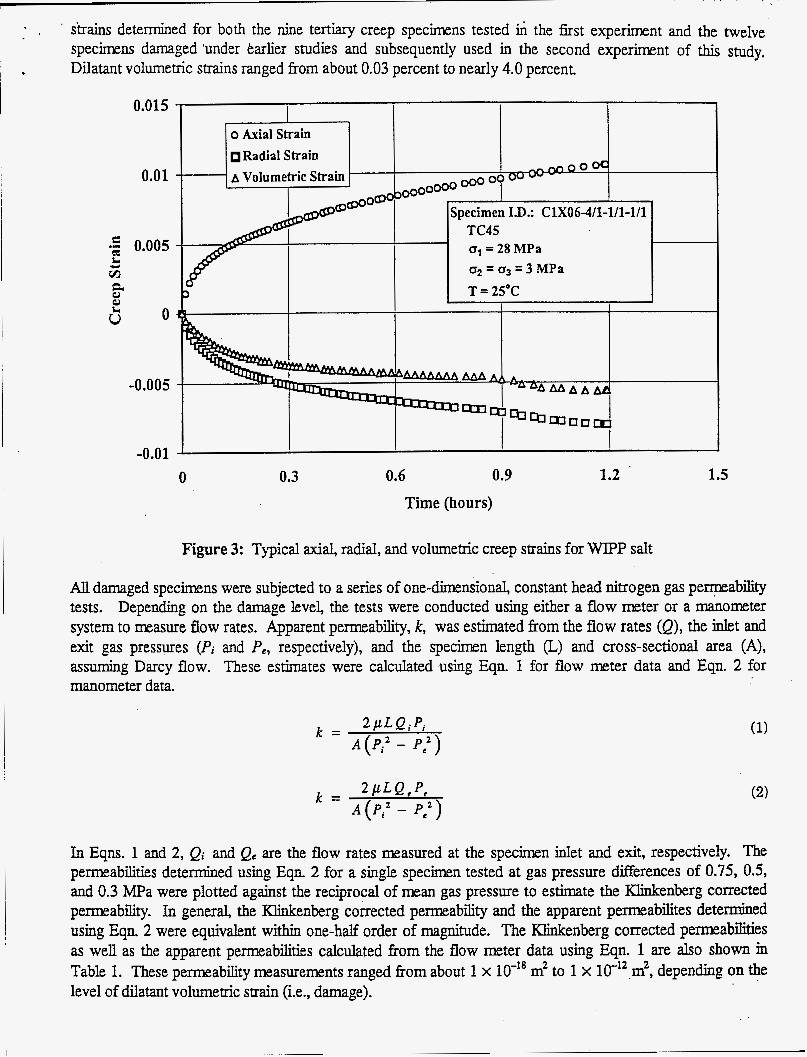
- , . strains determined for both the nine tertiary creep specimens tested h the hrst experiment and the twelve spechrens damaged 'under tarlier studies and subsequently used in the second experiment of this study. Dilatant volumetric strains ranged from about 0.03 percent to nearly 4.0 percent.
0.015
0.01
0
-0.005
-0.01 0
i-1-1 o Axial Strain I Radial Strain
- 0 0 O d A Volumetric Strain
~ A 0 Specimen I.D.: ClX06-4/1-1/1-1/1 TC45 o1 = 28 MPa o2 = cr, = 3 MPa T = 25°C I
I I
0.3 0.6 0.9 Time (hours)
1.2 1.5
Figure 3: Typical axial, radial, and volumetric creep strains for W P salt
AU damaged specimens were subjected to a series of one-dimensional, constant head nitrogen gas permeability tests. Depending on the damage level, the tests were conducted using either a flow meter or a manometer system to measure flow rates. Apparent permeability, k, was estimated from the flow rates (Q), the inlet and exit gas pressures (Pi and P,, respectively), and the specimen length Q and cross-sectional area (A), assuming Darcy flow. These estimates were calculated using Eqn. 1 for flow meter data and Eqn. 2 for manometer data
k = W L Q A A ( P i 2 - P:)
In Eqns. 1 and 2, Qi and Qc are the flow rates measured at the specimen inlet and exit, respectively. The permeabilities determined using Eqn. 2 for a single specimen tested at gas pressure differences of 0.75, 0.5, and 0.3 MPa were plotted against the reciprocal of mean gas pressure to estimate the Klinkenberg corrected pemability. In general, the Klinkenberg corrected permeability and the apparent permeabilites determined using Eqn. 2 were equivalent within one-half order of magnitude. The Klinkenberg corrected permeabilities as well as the apparent permeabilities calculated from the flow meter data using Eqn. 1 are also shown in
level of dilatant volumetric strain (Le., damage). Table 1. These permeability measurements ranged from about 1 x m2 to 1 x 10 -12 m 2 , depending on the

TABLE 1 8 DILATANT VOLUMETRIC STRPJN AND PERMEABILITY FOR W P SALT
r c36
Dilatant
Strain Permeability“
4.45 x 10-l~ (F 1.88 x 10⁻¹~ (F
0.01 17
1.09 x 10⁻¹~ (F: 0.0026
LCH007
LCHOO9
XH010
XHO11
XH013
XHO15
4.45 x 10-l6 (F: TC44 0.0019 3.02 x (F:
0.0024 3.71 x (M
0.0042 2.61 x 10-l~ (F: 2.34 x 10-l~ E 2.64 x io-” (F:
2.73 x (F:
7.42 x io-’’ 0
8.10 x 0 7.88 x 10⁴ 0 4.13 x 10-l~ 0 4.67 x 10-l~ 0
4.69 x 0 3.69 x 0 3.27 x o
0.0036 2-42 10-15 (F:
0.0006 1.04 x lo-’* (M
0.0043 9.94 X lo-’’ 0
0.0030 3.57 10-15 0
TC45
rc49
3.17 x 10-l~ 0 0.0024 2.07 x 10-l~ 0
1.86 x 10⁻¹~ 0
I
I 0.0003 I 8.71 x lo-” (MI rc5i
(a) Values in parentheses indicate measurement made either with a flow meter 0 or a manometer (M). Manometer values are Klinkenberg corrected.
Dilatant
Strain Permeability(‘
- Experiment No. 2 1
5.53 X (F TC16 0.005 1 3.72 x (F 1.66 x 10-l~ (F 1.42 x 10-l~ (F 4.72 x 10-l~ (F 4.17 x 10-l~ (F
TC33 0.0179
TC34 0.0248
TC35 0.0397 1.37 x lo-” (F 1.24 xlO-” (e
. _ 3.65 x 0 2.94 x 10-l~ 0 XHO16 I 0.0041 I 2.1 1 x (F) 3.29 x 10-l~ (F)
Permeability is plotted as a function of dilatant volumetric strain in Figure 4 and shows that the relationship
permeability changes by about 6 or 7 orders of magnitude over a range in dilatant volmtr ic strain of 0 to 0.5 percent, but then changes by only about 2 orders of magnitude over a range in dilatant volumetzic strain of 0.5 to 4 percent.
between the two is highly nonlinear. Assuming the permeability of intact salt is approximately 1 x 10 -21 m 2 ,

0
j 1 I f I
I
o Measured
1 1 1 Fitted - Blankenship Model t-
Figure 4: Permeability versus dilatant volumetric strain for WIPP salt

. . . . . . . . . . . . . . . . . . . . . . . . . . . . . . . . . . . . . . . . . . . . . . . . . . . . . . . . . . . . . . . . . . . . . . . . . . . . . . . . . . . . . . . . . . . . . ~~~~
. . . . . . . . . . . . .
b Two s w l e models have been postulated to characterize the permeability versus dilatant volumetric strain relationship for salt' Peach'(1991) assumed a physically based model that can be expressed as follows:
k = P E S while Blankenship (1996) proposed a three parameter empirical model that can be expressed as follows:
k = Aexp(B~:)
(3)
(4)
where E, iS the dilatant volumetric strain, and p, A, B, and C are fitting parameters. The A parameter in the Blankenship (1996) model represents the permeability of undamaged salt (ie., the value when = 0). Both models were fitted to the data shown in Figure 4 using the SOLVE routine available in Microsoft EXCEL Version 7.0 for Windows95 to obtain estimates for the fitting parameters. These fits to the data are shown in Figure 4 along with estimates of the fitting parameters. It iS interesting to note that the A parameter in the Blankenship (1996) model is within 1 order of magnitude of the assumed permeability of native undamaged WIPP salt; whereas, the Peach (1991) model predicts k = 0 at E,, = 0.
CONCLUDING REMARKS
The results presented in this paper establish a preliminary relationship between permeability and micro- fracture-induced damage for clean WIPP rock salt. The relationship is considered valid over a range in dilatant volumetric strain from 0.03 to about 4 percent. Over this range, the permeability increases approximately 9 orders of magnitude. Damage was induced through a series of triaxiaI compression tertiary creep tests that simulated the stress state expected to exist in the salt near a typical WIPP opening. Based on this study, the permeability in the DRZ around WDPP openings may be significantly enhanced; however, this enhanced permeability has been accounted for in the seal design. In addition, the damage is expected to heal with time as the deviatoric stresses in the salt are reduced because of the buildup of back pressures in the seal materials caused by creep closure of the sealed openings.
Sandia is a multiprogram laboratory operated by Sandia Corporation, a Lockheed Martin Company, for the United States Department of Energy under Contract DE-Ac04-94~~85000. REFERENCES
Blankenship, D.A., Fitting of RE/SPEC Inc. and Stormont Permeability Versus Volumetric Strain Data, 1996, Calculation File 325/09/03, prepared by RE/SPEC Inc., Rapid City, SD, for Sandia National Laboratories, Albuquerque, NM.
, . __.
Brodsky, N.S., Crack Closure and Healing Studies in WIPP Salt Using Compressional Wave Velocity and Attenuation Measurements: Test Methods and Results, 1990, SAND90-7076, prepared by RE/SPEC Inc., Rapid City, SD, for Sandia National Laboratories, Albuquerque, NM.
- Dale, T., Hurtado, L.D., WIPP &-Intake Shaft Disturbed Rock Zone Study, Proceedings of the 4th Conference on the Mechanical Behavior of Salt, 1996, Montreal, QuCbec, Canada, June, 276-281.
Peach, C.J., Ultraiectina, 1991, ISSN 0072-1027: No. 77, Utrecht, Netherlands.
Influence of Defomtion on the Fluid Transport Properties of Salt Rocks, Geologica
Sandia National Laboratories, Waste Isolation Pilot Plant Shaft Sealing System Compliance Submittal Design Report, 1996, SAND96-1326, Sandia National Laboratories, Albuquerque, NM.
Stormont, J.C., Discontinuous Behavior Near Excavations in a Bedded Salt Formation, Intemtiunal Journal ofMininP nnd &n!noir Fnoinpprino 1 9 Q l L C A m 0 ?m?T Qf 1 1 qL

M98004242 1111111\\111111111lllllllllll11111111111111111111111
Publ. Date (11)
Sponsor Code (1 8) U C Category (1 9)
DOE