experimental evaluation of the prevention methods for the ... · in the case of buildings with...
TRANSCRIPT

Volume 6, Number 5 (October 2013) p. 765-782 • ISSN 1983-4195
© 2013 IBRACON
Cracks that form at the interfaces between masonry structures are common uncontrolled occurrences in buildings. Numerous methods have been proposed by the construction industry to address this problem. Cracks continuously form in the joints between concrete columns and masonry infill walls. In this study, the most common methods for preventing these types of cracks were evaluated in laboratory experiments. Column masonry models were constructed using different types of joints between concrete columns and masonry infill walls, such as steel bars and steel mesh. The efficiency of each type of joint method was evaluated by performing direct tensile tests (pullout tests) on the models and monitoring the evolution of the crack opening in the joint between the column and wall, as a function of load applied to the model. The results from this study indicate that the model composed of “electrowelded wire mesh without steel angles” is the best model for controlling cracking in the joints between concrete columns and masonry infill walls.
Keywords: masonry, cracks, electrowelded metallic screen.
As fissuras na interface alvenaria/estrutura são ocorrências patológicas comuns nas edificações e muitos são os métodos propostos pela indús-tria da construção que prometem evitar este problema. De caráter recorrente encontram-se as fissuras na ligação pilar de concreto e parede de alvenaria. Neste trabalho, são avaliados, em laboratório, os métodos mais usuais de prevenção deste tipo de fissura. Modelos pilar/alvenaria foram construídos utilizando-se diferentes tipologias de ligação entre o pilar de concreto e a parede de alvenaria, desde o usual “ferro cabelo” até telas de aço. A eficiência de cada um destes métodos de ligação foi avaliada por intermédio de ensaio dos modelos à tração direta, com o monitoramento da evolução da abertura da fissura na ligação pilar/parede em função do incremento de carga aplicada ao modelo. Os resultados desta pesquisa indicaram o modelo composto por “tela metálica eletrossoldada, e sem cantoneira de aço”, como a melhor técnica de controle da fissuração na ligação pilar de concreto e parede de alvenaria, dentre todos os modelos avaliados.
Palavras-chave: alvenaria, fissuras, tela eletrosoldada.
Experimental evaluation of the prevention methods for the interface between masonry infill walls and concrete columns
Avaliação experimental dos métodos de prevenção de fissuras na interface alvenaria de vedação e pilar de concreto
A. P. TRAMONTIN a
A. L. MORENO JUNIOR b
C. R OLIVEIRA c
a UNICAMP, Department of Structures, School of Civil Engineering, Architecture and Urban Planning, [email protected], address: UNICAMP, Departamento de Estruturas, Faculdade de Engenharia Civil, Arquitetura e Urbanismo; Rua Saturnino de Brito nº. 135, Laboratório de Estruturas. CEP: 13083-852, CP 6021, Cidade Universitária Zeferino Vaz s/nº –Distrito de Barão Geraldo, Campinas–SP–Brazil.b UNICAMP, Department of Structures, School of Civil Engineering, Architecture and Urban Planning, [email protected], address: UNICAMP, Departamento de Estruturas, Faculdade de Engenharia Civil, Arquitetura e Urbanismo; Rua Saturnino de Brito nº. 135, Laboratório de Estruturas. CEP: 13083-852, CP 6021, Cidade Universitária Zeferino Vaz s/nº –Distrito de Barão Geraldo, Campinas–SP–Brazil.c UNICAMP, Department of Structures, School of Civil Engineering, Architecture and Urban Planning, [email protected], address: UNICAMP, Departamento de Estruturas, Faculdade de Engenharia Civil, Arquitetura e Urbanismo; Rua Saturnino de Brito nº. 135, Laboratório de Estruturas. CEP: 13083-852, CP 6021, Cidade Universitária Zeferino Vaz s/nº –Distrito de Barão Geraldo, Campinas–SP–Brazil.
Received: 03 Aug 2012 • Accepted: 21 May 2013 • Available Online: 11 Oct 2013
Abstract
Resumo
766 IBRACON Structures and Materials Journal • 2013 • vol. 6 • nº 5
Experimental evaluation of the prevention methods for the interface between masonry infill walls and concrete columns
1. Introduction
Due to the soaring housing deficit in Brazil, the accelerated pace of the construction industry has frequently produced unsatisfac-tory results with regard to building performance. This poor perfor-mance is translated into extreme problems that impact the safety and comfort of buildings.The occurrence of cracks constitutes a recurrent problem in civil construction. According to [1], the primary causes of this recur-rence include the lack of professional qualifications, the use of ma-terials that are noncompliant with current standards and specifica-tions, inadequate construction techniques, improper construction management and design failures.In the case of buildings with reinforced concrete structures and masonry infill walls, the increasing trend of slender building con-struction contributes to poor building performance. Slender struc-tures produce greater deformations than wide structures.During deformation, a concrete structure imposes loads on ma-sonry infill walls because they resist structural displacements. The greater the imposed displacements, the greater the probability that the masonry infill walls will be subjected to loads.A current increase in crack formation in reinforced concrete struc-tures with masonry infill walls indicate that current preventative techniques require adaptation to new performance and behavior criteria (particularly regarding slenderness) for buildings.Because numerous variables with a significant interdependence are involved, the evaluation of construction methods for the pre-vention of or reduction in cracks is a complex problem. Load dis-tribution in a masonry infill wall and the physical and mechanical properties of wall components (masonry and bedding mortar ele-ments) are critical variables of this problem.Due to the large number of variables, the interdependence of these variables and the isolated influence of each variable on the be-havior of a wall, the issue of cracking is a classical experimental problem in which new crack prevention techniques are evaluated in a laboratory environment. Due to technical limitations and exorbitant costs, it is frequently unfeasible to reproduce the real behavior of a masonry infill wall in service situations in a laboratory. In these cases, the use of small-scale models to evaluate the efficiency of crack prevention tech-niques is a viable alternative.To contribute experimental results to existing technical literature, various common devices used for preventing cracks, which occur in the joint between the masonry wall and the concrete structure (column), are evaluated using a reduced model in this study. The cited evaluation proposal can be employed to select a technique prior to a laboratory test (in which the actual size of the wall yields a significantly higher cost).
2. Cracking in masonry infill walls
A masonry infill wall consists of masonry elements (blocks or solid bricks) joined by bedding mortar joints. These materials possess individual physical and mechanical properties that work together to fulfill the sealing function of a wall.In terms of performance, the infill wall is expected to be conceived, executed and used according to specific safety, durability, fire-re-sistant, thermal comfort, acoustic comfort and air tightness criteria. Criteria that are related to aesthetics and cost are also cited factors.
When certain requirements are either not considered or are con-sidered according to criteria without appropriate technical/scientific evidence, extreme problems can occur in the masonry infill walls, such as cracking. Regarding potential causes of cracks, [2] cites deficiencies in the constituent materials, design errors, defects in execution, acci-dents, use and/or inadequate maintenance as primary contributing factors [2].The same author [2] classifies the direct causes of cracks in ma-sonry infill walls as follows: foundation movement, excessive struc-tural deformations, temperature variations, humidity variations, ex-ecution defects and generic causes, such as cracks from chemical reactions of the materials that comprise the wall to vibrations of the wall. This second classification has proven more useful for the diagnosis and repair of the problem.Similarly, [3] states that cracks are also attributed to stresses from overloads or to the movements of materials, components or the entire structure.According to [4], the causes of cracking in the masonry infill walls of tall buildings include the incompatibility of structural deformations compared with the capacity of accommodating deformations and the strength of the vertical seals. Masonry infill walls are either in contact with or supported on structural components (slabs, beams and columns); thus, their strength behaviors are interrelated.Currently, there is a trend toward a significant increase in cracking in masonry infill walls, which is generated by the incompatibility of deformation between the masonry and the structure. As previ-ously noted by [5] and [6], slender structures are designed with an increased number of beam spans and a decreased number of column sections. These deformable structures impose these de-formations on the masonry that covers the structures, which gener-ates stresses that the masonry was not designed to endure. There-fore, the probability of cracking in the wall or in the region of the joint between the wall and the structure increases.Cracking in the region of the connection between the wall and
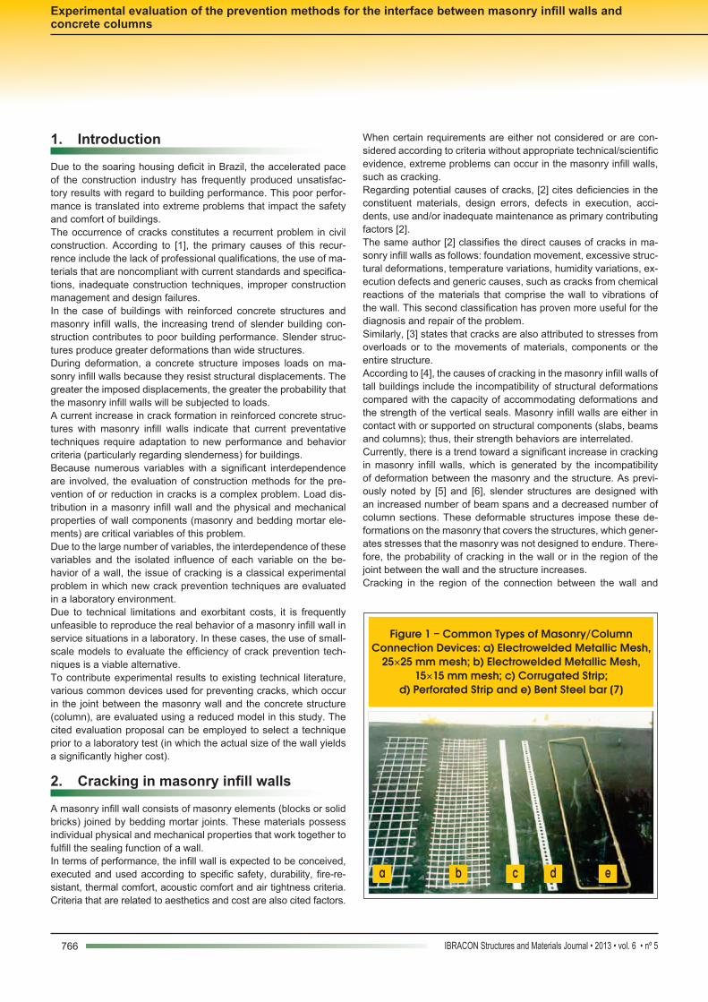
Figure 1 – Common Types of Masonry/Column Connection Devices: a) Electrowelded Metallic Mesh,
25×25 mm mesh; b) Electrowelded Metallic Mesh, 15×15 mm mesh; c) Corrugated Strip;
d) Perforated Strip and e) Bent Steel bar [7]
b c d ea
767IBRACON Structures and Materials Journal • 2013 • vol. 6 • nº 5
A. P. TRAMONTIN | A. L. MORENO JUNIOR | C. R OLIVEIRA
to the laying joints. Previous pullout tests of the joints, with anchor-ing lengths of 30 cm or 40 cm, indicated that an anchoring length of 40 cm was the most efficient length. The methodology for these pullout tests is described in the subsequent section.Another parameter of interest that is analyzed in this study is the efficiency of the increased surface roughness of the column face, which is in contact with the masonry wall. The column face was treated with cement mortar, sand and acrylic adhesive additive.The following parameters were kept constant in the proposed comparative evaluation: the type of masonry infill (ceramic block with a width of 14 cm, a height of 19 cm and a length of 39 cm) the bedding mortar (industrial mortar), the concrete in the columns and the previous compression stress applied to the masonry.Connection devices consisting of steel bars with diameters of 5.0 mm and 6.3 mm were evaluated. In the case of the steel mesh, a screen with a square mesh of 15 cm and a wire diameter of 1.65 mm was used.
the structure generally occurs when the masonry infill wall resists the cited stresses (from deformations imposed by the deformable structure). However, the joint between the masonry and the struc-ture does not resist these stresses. In this case, cracks appear along the joints (masonry/structure interface).Currently, numerous techniques for treating the joint between the wall and the structure to prevent cracks or limit their openings to acceptable values are available with regard to the performance of the masonry infill wall. The adoption of metallic reinforcements has been suggested by [7], [8] and [9] to support the stresses acting on the most loaded regions or the control joints, which enable the dissipation of these stresses.The use of metallic reinforcements to prevent cracking in the joint between the wall and the column, the use of steel bars (bars com-posed of steel, which are used in reinforced concrete, with thick-nesses between 4 and 6 mm) or the use of electrowelded wire mesh composed of small-diameter wires fixed with pins, washers or angles on the concrete column are prevalent in the Brazilian civil construction industry (Figures [1] to [3]).These methods have proved inefficient. Thus, the objective of this study was to evaluate the efficiency of these methods in prevent-ing cracks that occur between the masonry infill wall and the con-crete column using laboratory experiments.
3. Materials and experimental program
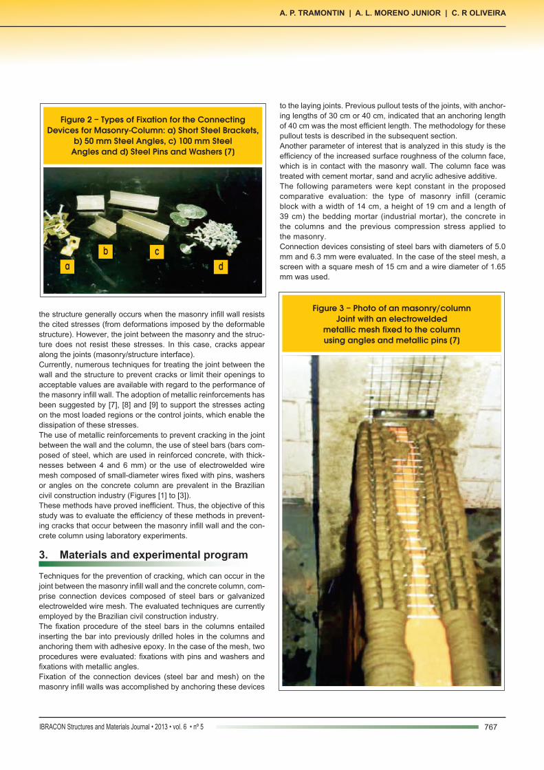
Techniques for the prevention of cracking, which can occur in the joint between the masonry infill wall and the concrete column, com-prise connection devices composed of steel bars or galvanized electrowelded wire mesh. The evaluated techniques are currently employed by the Brazilian civil construction industry.The fixation procedure of the steel bars in the columns entailed inserting the bar into previously drilled holes in the columns and anchoring them with adhesive epoxy. In the case of the mesh, two procedures were evaluated: fixations with pins and washers and fixations with metallic angles.Fixation of the connection devices (steel bar and mesh) on the masonry infill walls was accomplished by anchoring these devices
Figure 2 – Types of Fixation for the Connecting Devices for Masonry-Column: a) Short Steel Brackets,
b) 50 mm Steel Angles, c) 100 mm Steel Angles and d) Steel Pins and Washers [7]
b cda
Figure 3 – Photo of an masonry/column Joint with an electrowelded
metallic mesh fixed to the column using angles and metallic pins [7]

768 IBRACON Structures and Materials Journal • 2013 • vol. 6 • nº 5
Experimental evaluation of the prevention methods for the interface between masonry infill walls and concrete columns
ceramic sealing blocks laid with industrial bagged mortar. Steel bars (5.0 or 6.3 mm) or mesh with lengths of 30 cm or 40 cm were inserted in the laying joints of these prisms.The test consisted of pulling out the connecting device from the mortar joint. A special device was constructed for this test. The prisms were placed between metallic sheets in the device, which were connected by threaded rods and designed to apply a con-trolled compression force on the faces of the blocks using a nut tightening system. This test arrangement was required to simulate a service situation to which the masonry walls are subjected, in which the connection devices exert a compression from the weight of the masonry wall.An estimated compression force of 15 kN was applied to the prisms, which is equivalent to the predicted force in a joint located at the midpoint of a masonry wall with a ceiling height of 3.0 m. The control of this previous joint loading occurred through the instru-mentation of the rod bars, in which electrical strain gauges were placed.Figure [4] illustrates the arrangement of the proposed pullout test and the fixation of the steel plates on large concrete blocks. The horizontal displacement of the system is released on application of the compression force on the blocks. As the nuts are tightened, one set of the plates moves and applies the compression force to the prisms.Deflectometers were also installed at various points on the block surface and the connecting device (bar or mesh) to obtain the dis-placement of the anchoring device in this region (Figure [5]). Note that in a real situation, this displacement can result in crack open-ing, which the technique seeks to prevent.With the prism appropriately positioned in the device and pre-compressed, the pullout test was conducted with the connection
Considering the previously described variables, the following mod-els were evaluated in the laboratory:n 5.0 mm steel bar and a pretreated column surface;n 5.0 mm steel bar and a pretreated column surface;n 6.3 mm steel bar and a pretreated column surface;n 6.3 mm steel bar and a pretreated column surface.n Steel mesh fixed on the column with pins and washers and a
pretreated column surface;n Steel mesh fixed on the column with pins and washers and a
pretreated column surface;n Steel mesh fixed on the column with metallic angles and a pre-
treated column surface and;n Steel mesh fixed on the column by angles and an untreated
column surface.For each of these eight models, four samples were created for analyzing by the direct tensile test (pullout test). The methodology of these tests is described in the subsequent section.The results of the characterization of the materials used in this study are also described. Ceramic block, concrete, bedding mor-tar, steel bars and mesh were characterized based on their physi-cal and mechanical properties.
3.1 Methodology employed in the pullout tests on the connecting device (steel mesh or bar) for the bedding mortar
The tests were performed to evaluate whether the lengths em-ployed in the construction industry, such as 30 cm or 40 cm, are the most appropriate lengths for anchoring the connecting device (steel bar or mesh) to the laying joint of the masonry walls.For this evaluation, masonry prisms were constructed with two
Figure 4 – Detail of the arrangement in the pullout test of the column/wall connecting device of the mortar joint from masonry prisms

769IBRACON Structures and Materials Journal • 2013 • vol. 6 • nº 5
A. P. TRAMONTIN | A. L. MORENO JUNIOR | C. R OLIVEIRA
device, which was pulled until rupture due to the loss of anchoring (pullout). Figure [6] illustrates the execution of this test for the case of the electrowelded mesh.
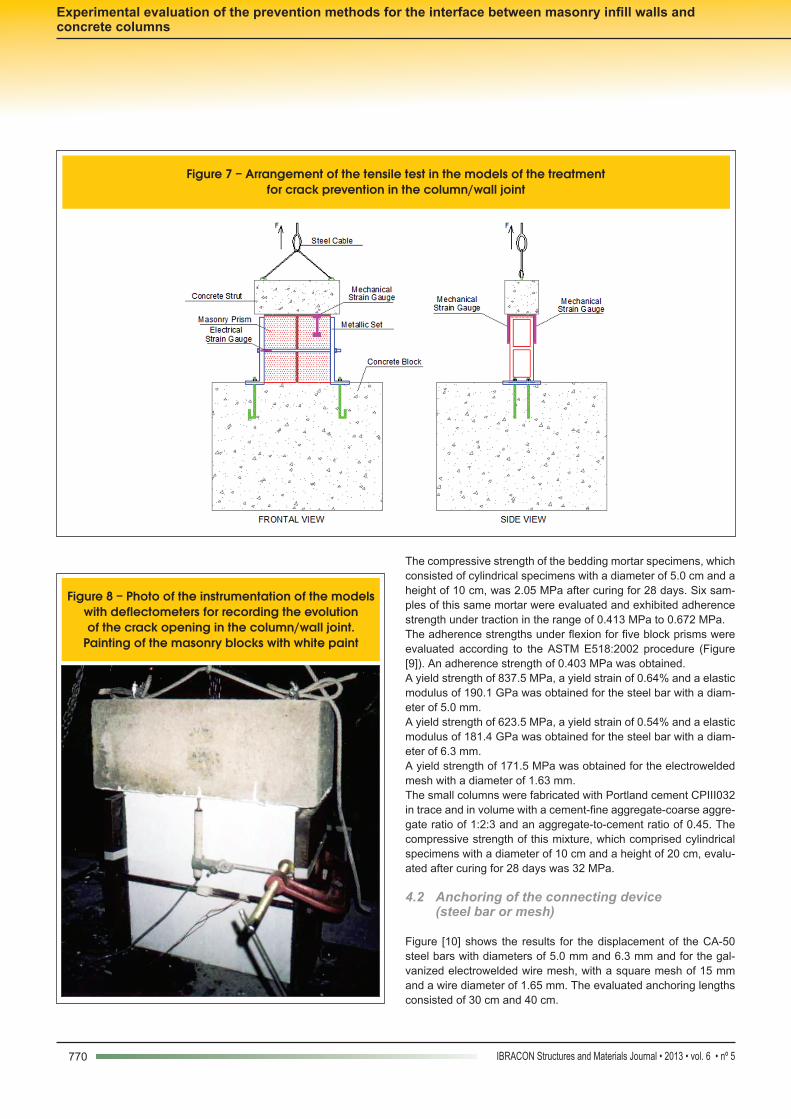
3.2 Pullout test methodology for the crack prevention models at the interface between the concrete column and masonry wall
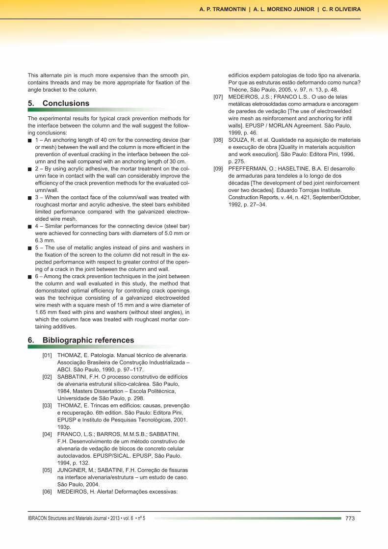
Thirty-two samples, which consisted of four samples for each of the eight proposed models, were created in the laboratory.A concrete column was constructed with a square cross-section containing a width of 20 cm and a length of 50 cm. The connecting devices (bar or mesh) were installed in this column. The steel bar was inserted in previously drilled holes in the column and anchored with adhesive. The mesh was connected to the column with pins and washers or metallic angles.The prisms, which consisted of two ceramic blocks, were posi-tioned on the side face of the columns with an installed connecting device (bar or mesh). The prisms were positioned such that the connection devices (bar or mesh) were inserted into the laying joint between the blocks, with anchoring lengths of 40 cm (the length that was most efficient in the previously described pullout tests).In certain models, the column face in contact with the ceramic blocks was treated with mortar containing an acrylic adhesive additive.The models were positioned on the same device used for the pull-out test of the connecting devices and, using a similar arrange-ment, the prisms were pre-compressed to simulate the situation in service that was previously justified.After positioned in the equipment, the joints of the models were subjected to a direct traction test as illustrated in Figure [7]. With the prism (wall) fixed to the equipment and the cables connected to the column, the system was pulled until the moment at which an observer 50 cm from the model observed the first crack.In this test, the evolution of the crack opening in the joint between the column and wall was also evaluated as a function of the load applied to the model. Figure [8] illustrates the positioning of the de-
flectometers in the region and a scheme used to make the cracks more distinct to the observer: painting of the ceramic blocks with white latex paint.
4. Results and discussion
4.1 Material characterization tests
The materials, ceramic block, bedding mortar, steel bars with di-ameters of 5.0 mm and 6.3 mm, electrowelded mesh and concrete were characterized by their physical and mechanical properties ac-cording to current Brazilian national standards.The ceramic block exhibited a compressive strength of 2.11 MPa and 9.32% water absorption.
Figure 5 – Detail of the masonry/positioned column connecting device of the evaluatedanchoring lengths in the laying joint of the masonry prism
Figure 6 – Photo of the arrangement of the pullout test of the column/masonry connecting device. The pullout test
for the electrowelded mesh
770 IBRACON Structures and Materials Journal • 2013 • vol. 6 • nº 5
Experimental evaluation of the prevention methods for the interface between masonry infill walls and concrete columns
The compressive strength of the bedding mortar specimens, which consisted of cylindrical specimens with a diameter of 5.0 cm and a height of 10 cm, was 2.05 MPa after curing for 28 days. Six sam-ples of this same mortar were evaluated and exhibited adherence strength under traction in the range of 0.413 MPa to 0.672 MPa.The adherence strengths under flexion for five block prisms were evaluated according to the ASTM E518:2002 procedure (Figure [9]). An adherence strength of 0.403 MPa was obtained.A yield strength of 837.5 MPa, a yield strain of 0.64% and a elastic modulus of 190.1 GPa was obtained for the steel bar with a diam-eter of 5.0 mm.A yield strength of 623.5 MPa, a yield strain of 0.54% and a elastic modulus of 181.4 GPa was obtained for the steel bar with a diam-eter of 6.3 mm.A yield strength of 171.5 MPa was obtained for the electrowelded mesh with a diameter of 1.63 mm.The small columns were fabricated with Portland cement CPIII032 in trace and in volume with a cement-fine aggregate-coarse aggre-gate ratio of 1:2:3 and an aggregate-to-cement ratio of 0.45. The compressive strength of this mixture, which comprised cylindrical specimens with a diameter of 10 cm and a height of 20 cm, evalu-ated after curing for 28 days was 32 MPa.
4.2 Anchoring of the connecting device (steel bar or mesh)
Figure [10] shows the results for the displacement of the CA-50 steel bars with diameters of 5.0 mm and 6.3 mm and for the gal-vanized electrowelded wire mesh, with a square mesh of 15 mm and a wire diameter of 1.65 mm. The evaluated anchoring lengths consisted of 30 cm and 40 cm.
Figure 7 – Arrangement of the tensile test in the models of the treatmentfor crack prevention in the column/wall joint
Figure 8 – Photo of the instrumentation of the models with deflectometers for recording the evolution of the crack opening in the column/wall joint.
Painting of the masonry blocks with white paint

771IBRACON Structures and Materials Journal • 2013 • vol. 6 • nº 5
A. P. TRAMONTIN | A. L. MORENO JUNIOR | C. R OLIVEIRA
Figure [10] illustrates similar behavior for the three devices. Both of the steel bars and the mesh exhibit significantly higher displacement values for an anchoring length of 30 cm compared with a length of 40 cm. In the case of the 5.0 mm diameter steel bar for a pullout loading equivalent to 450 daN, the displacement value was three times greater than the displacement value obtained for an anchoring length of 40 cm.In an initial analysis that compares the evaluated anchoring lengths, the 40 cm length is determined to be the optimal length, which justifies its use in the execution of the eight proposed mod-els for crack prevention at the interface between the column and wall in this study.
Figure 9 – Photo of the test for evaluation of the mortar adherence
strength in flexion. Prism of ceramic blocks positioned for the test
Figure 10 – Results of the pullout test of the connecting devices from the joint of the bedding mortar
Figure 11 – Results of the evolution of the opening of the crack in the column/wall joint for the evaluated prevention techniques

772 IBRACON Structures and Materials Journal • 2013 • vol. 6 • nº 5
Experimental evaluation of the prevention methods for the interface between masonry infill walls and concrete columns
Although the evaluated anchoring lengths (30 cm or 40 cm) are prevalent in the Brazilian construction industry for crack preven-tion methodologies at the interface between the column and the wall, rupture occurred from pullout of the connecting device (bar or mesh) prior to the yield point of the steel in all evaluated samples. This situation may not be appropriate for the prevention system of cracks in the joints between columns and walls due to the crack openings and the displacements of the connecting device in the mortar joint. These values are significant, as indicated by the re-sults shown in Figure [10].
4.3 Cracking in the concrete column/masonry wall connecting joint
Figure [11] illustrates the evolution of the values for crack openings in the joint between the column and the wall as a function of the loading in traction applied to the evaluated models, until the occur-rence of the first visible crack (opening of approximately 0.1 mm).Figure [11] reveals that the models composed of steel bars with di-ameters of 5.0 mm and 6.3 mm, with a surface treatment applied to the common face of the column/wall, exhibited identical behavior during the tests. This finding suggests that the use of the 6.3 mm diameter may not produce the smallest crack opening.Regarding the choice of mesh or steel bar as a connecting device, the results shown in Figure [11] suggest a slight advantage for mesh. In general, the evolution of the crack opening in the joint be-
tween the column and the wall was much more controlled with the use of the mesh, particularly for the models in which the column surface was treated with mortar.With respect to the efficiency of the treatment of the column face with mortar, a significant improvement in behavior was perceived in relation to the evolution of the crack opening for the models that employed this treatment compared with the same models without the cited treatment of the column face with mortar. The evaluation of the behavior of the models, for any of the evaluated connect-ing devices (bar or mesh), suggests an efficiency of approximately 40%. The probable increase of the adherence between the column and the wall altered the overall behavior of the joint. Forms of rup-ture typical to the models both with additive mortar treatment and without additive mortar treatment are illustrated in Figures [12] and [13], respectively.Regarding the use of the metallic angles for connecting the mesh to the concrete column, the results indicate that their use is not justifiable. In the case of the models in which the column face was treated with mortar and acrylic adhesive, the results of the evolu-tion of the crack opening are similar for both types of evaluated connections. In the case of the models without the a treated col-umn surface, the results demonstrate better efficiency with the use of pins and washers.The use of angles for connecting the mesh to the concrete column is expected to increase the resistance to crack openings at the interface between the column and wall. This unexpected behavior may be explained by the reduction in length of the pin in the col-umn, as a function of the thickness of the angles, and the use of the smooth pins.Note that an alternative to the smooth pin used in this study is available to builders for fixation of the steel angles to the column.
Figure 12 – Photo of typical rupture in the model without treatment of the column face
with mortar containing additives
Figure 13 – Photo of typical rupture in the model with treatment of the column face with mortar containing additives
773IBRACON Structures and Materials Journal • 2013 • vol. 6 • nº 5
A. P. TRAMONTIN | A. L. MORENO JUNIOR | C. R OLIVEIRA
This alternate pin is much more expensive than the smooth pin, contains threads and may be more appropriate for fixation of the angle bracket to the column.
5. Conclusions
The experimental results for typical crack prevention methods for the interface between the column and the wall suggest the follow-ing conclusions:n 1 – An anchoring length of 40 cm for the connecting device (bar
or mesh) between the wall and the column is more efficient in the prevention of eventual cracking in the interface between the col-umn and the wall compared with an anchoring length of 30 cm.
n 2 – By using acrylic adhesive, the mortar treatment on the col-umn face in contact with the wall can considerably improve the efficiency of the crack prevention methods for the evaluated col-umn/wall.
n 3 – When the contact face of the column/wall was treated with roughcast mortar and acrylic adhesive, the steel bars exhibited limited performance compared with the galvanized electrow-elded wire mesh.
n 4 – Similar performances for the connecting device (steel bar) were achieved for connecting bars with diameters of 5.0 mm or 6.3 mm.
n 5 – The use of metallic angles instead of pins and washers in the fixation of the screen to the column did not result in the ex-pected performance with respect to greater control of the open-ing of a crack in the joint between the column and wall.
n 6 – Among the crack prevention techniques in the joint between the column and wall evaluated in this study, the method that demonstrated optimal efficiency for controlling crack openings was the technique consisting of a galvanized electrowelded wire mesh with a square mesh of 15 mm and a wire diameter of 1.65 mm fixed with pins and washers (without steel angles), in which the column face was treated with roughcast mortar con-taining additives.
6. Bibliographic references
[01] THOMAZ, E. Patologia. Manual técnico de alvenaria. Associação Brasileira de Construção Industrializada –
ABCI. São Paulo, 1990, p. 97–117. [02] SABBATINI, F.H. O processo construtivo de edifícios de alvenaria estrutural sílico-calcárea. São Paulo,
1984, Masters Dissertation – Escola Politécnica, Universidade de São Paulo, p. 298. [03] THOMAZ, E. Trincas em edifícios: causas, prevenção e recuperação. 6th edition. São Paulo: Editora Pini, EPUSP e Instituto de Pesquisas Tecnológicas, 2001.
193p. [04] FRANCO, L.S.; BARROS, M.M.S.B.; SABBATINI,
F.H. Desenvolvimento de um método construtivo de alvenaria de vedação de blocos de concreto celular autoclavados. EPUSP/SICAL. EPUSP, São Paulo. 1994, p. 132.
[05] JUNGINER, M.; SABATINI, F.H. Correção de fissuras na interface alvenaria/estrutura – um estudo de caso. São Paulo, 2004.
[06] MEDEIROS, H. Alerta! Deformações excessivas:
edifícios expõem patologias de todo tipo na alvenaria. Por que as estruturas estão deformando como nunca? Thécne, São Paulo, 2005, v. 97, n. 13, p. 48. [07] MEDEIROS, J.S.; FRANCO L.S.. O uso de telas
metálicas eletrosoldadas como armadura e ancoragem de paredes de vedação [The use of electrowelded wire mesh as reinforcement and anchoring for infill
walls]. EPUSP / MORLAN Agreement. São Paulo, 1999, p. 46.
[08] SOUZA, R. et al. Qualidade na aquisição de materiais e execução de obra [Quality in materials acquisition and work execution]. São Paulo: Editora Pini, 1996, p. 275. [09] PFEFFERMAN, O.; HASELTINE, B.A. El desarrollo de armaduras para tendeles a lo longo de dos décadas [The development of bed joint reinforcement over two decades]. Eduardo Torrojas Institute. Construction Reports, v. 44, n. 421, September/October, 1992, p. 27–34.