experimental investigation on … investigation on integrated wickless heat pipe for solar water...
TRANSCRIPT

VOL. 13, NO. 3, FEBRUARY 2018 ISSN 1819-6608
ARPN Journal of Engineering and Applied Sciences ©2006-2018 Asian Research Publishing Network (ARPN). All rights reserved.
www.arpnjournals.com
770
EXPERIMENTAL INVESTIGATION ON INTEGRATED WICKLESS
HEAT PIPE FOR SOLAR WATER HEATING
Ahmed Jabbar Hasan and Mohammed Hasan Abood
Department of Mechanical Engineering, Karbala University, Karbala, Iraq
E-Mail: [email protected]
ABSTRACT
An integrated shape wickless heat pipe (WHP) inserted in flat plate solar collector (FPSC) is built and tested
experimentally by a solar simulation using halogen projectors. The WHP made of copper with multi evaporator tubs and
single horizontal condenser tube. It was tested for various evaporator diameter with distilled water as working fluid of fill
ratios (40, 60, and 80) % and (450, 650, and 850) W/m2 input heat flux to the solar collector at (30, 50, 70, and 90)⁰
inclined angles. Results show that evaporator temperature and heat transfer coefficients are increase with input heat flux
while thermal resistance decreases. Fill ratio have the direct effect on WHP performance and collector efficiency.
Keywords: wickless heat pipe, thermosyphon, solar simulation, flat plate collector.
List of symbol
A: Surface area [m2]
cp: Specific heat at constant pressure[J/kg.K]
d: Diameter[m]
FPSC: Flat Plate Solar Collector
FR: Working fluid fill charge ratio (of evaporator
volume)[%]
h: Heat transfer coefficient [W/m2.K]
I: Solar Insolation (radiation intensity)[W/m2]
K: Thermal conductivity[W/m.K]
L: Length[m]
m⁰: Mass flow rate[kg/s]
Q: Heat rate[W]
Qu: Overall useful heat energy gain[W]
q: Heat flux = Q/ A [W/m2]
T: Temperature[⁰C]
WHP: Wickless heat pipe
Greek symbols α: Absorptivity
β: Inclination angle from the horizontal[Degree]
Δ: Difference
ε: Emissivity
η: Efficiency
τ: Transmissivity
Subscripts
A: Ambient
co: Condenser
ev: Evaporator
i: Internal
l: Liquid
o: Outer
p: Plate
s: Surface
sat: Saturation
t: Total, top
INTRODUCTION The WHP is one of the most efficient devices in
the process of heat transfer where it’s a passive device that
doesn’t need outside power to run, and have a simply
structure with high capability of temperature control as
heat transfer in a high rate over small temperature
deference between its two ends[1, 2]. There are many
types and design of heat pipe but all depend on the
principle of latent heat of vaporization as a heat transfer
mode. Where the work principle of any heat pipe include
existence of a working fluid inside a container divided into
evaporator and condenser sections (with an adiabatic
section almost).The liquid in the evaporator section get
heat from outsource to vaporize and move toward the
condenser section due to vapor pressure difference, then
reject heat to a heat sink condensing vapor in to liquid
phase then condensed liquid driven back by a gravity force
to evaporator zone for WHPs where the condenser is
always hold above the evaporator section. The principle
work for integrated WHP shown in Figure-1.

VOL. 13, NO. 3, FEBRUARY 2018 ISSN 1819-6608
ARPN Journal of Engineering and Applied Sciences ©2006-2018 Asian Research Publishing Network (ARPN). All rights reserved.
www.arpnjournals.com
771
Figure-1.Wickless heat pipe work principle.
Many works study the effect of size, shape,
working fluid, fill ratios, and inclined angles on the
performance of WHPs.
Nioa, et al.[3,4] detected several parameters for
WHP experimentally include fill ratio, input power, and
aspect ratio using distilled water as working fluid. An
isothermal evaporator temperature distribution was
achieved from experiments. Later correlate empirical
relation for boiling coefficient inside the WHP evaporator
depending on the system pressure, heat flux, fill ratio, and
aspect ratio. It give good agree with his experimental data
and literature empirical relations.
While Jafari, et al.[5]studied the transient behaver
of WHP by numerical simulation and experimental test,
for purpose of maximum heat flux without dry out and
geyser boiling phenomena. A WHP made of copper with
internal diameter of 33mm and 500mm total length filled
with water from 16 to 135% for heat input between the
ranges of (30 to 700) W. They found that filling below
35% give better performance while the high fillings
caused the geyser boiling.
Heat pipe working fluid studded by Ma, et
al.[6]where they tested a WHP with eight refrigerant
working fluids for renewable energy and find small
differentiation between them.
Recently heat pipe heat exchanger is widely used
in solar applications for its high thermal performance. And
one of simplest and efficient application is the FPSC
where the WHP role in the solar collector is to replace the
riser tubes and transmit heat energy absorbed by the
collector plate into the agent fluid in a storage tank or heat
exchanger.
Khairnasov and Naumova [7]study the heat pipe
application to a solar system and find there is many types
of heat pipe can be used in solar application. Each one has
advantages and disadvantages but all types add a new
thermal resistance to the solar system, so that adding a
heat pipe should increases efficiency or give a simplicity
in assembly or other benefits to compensate its additional
thermal resistance. Also it found that Thermosyphon has
less thermal resistance than other heat pipes.
A comparison was made by Ordaz-Flores et
al.[8]between natural circulated Thermosyphon flat plate
solar collector and two phase close Thermosyphon system
with the same geometry and conditions but the close
system reject heat by a coil condenser heat exchanger
contained by storage tank. R134a and acetone were used
as working fluids. The R134a close cycle Thermosyphon
show better results in addition to some advantage like
avoiding frizzing, corrosion, fouling, and scaling
problems.
Azad[9] proposed a comparative method for
testing flat plate solar collectors with different shape to
absorb and extracted heat by installed them in parallel
positions and integrated the heat pipes as a single heat
pipe.
Some research for new shapes take only the
general performance without study parameters change
effect. Also outdoor testing doesn’t give accurate
comparison especially for solar application since it’s
effected by other environment parameters such as
variation in solar radiation, wind speed, shade effect, and
other non-controlled variables that may cause un right
judgment on one of the studded parameters.
In the present work testing integrated WHP for
FPSC by solar simulation and study the effect of fill ratio,

VOL. 13, NO. 3, FEBRUARY 2018 ISSN 1819-6608
ARPN Journal of Engineering and Applied Sciences ©2006-2018 Asian Research Publishing Network (ARPN). All rights reserved.
www.arpnjournals.com
772
diameter of evaporator tubes, input heat flux in solar
range, and system inclined angle on the performance of
WHP in laboratory under steady conditions.
Experimental apparatus and test procedure
Figure-2 represent experimental setup of WHP
solar system. Where an integrated multi - branch
evaporator consist of (12) cylindrical copper tubes
connected together from the bottom by (elbow and T
section joints) to form the evaporator structure. In this
method the liquid is distributed evenly into each tube. that
leads to made the WHP evaporator operate as a single
system with regular distribution of heat transfer process
and reduce the problems caused by dry out limitation as
there is always liquid in the bottom to compensate if any
tube test drying. The system, which contains an adiabatic
section, is connected from the top by a horizontal tube as a
condenser, with a diameter larger than the evaporator
tubes to increase the surface area of the condenser. The
horizontal shape enables to around it by other tube to
concentrate a double pipe heat exchanger.
Two of WHPs was belted with outer evaporator
tubes diameters of (19mm WHP1, and 16mm WHP2) with
1mm thickness for both WHPs evaporator tubes. Hence
the bottom joints take the same diameter for each WHP
with 40mm distance between tubes. The evaporator length
was 900mm separate by 85mm adiabatic section from
condenser tube of (720, 25.4, and 28) mm length, inner
and outer diameter respectively for both WHPs. The
condenser is surrounded by a 60 mm diameter pipe for
coolant fluid flow and covered as well as adiabatic section
by 50mm thickness glass wool insulation to prevent heat
losses to ambient.
The WHPs inserted to a FPSC of aluminum
absorber plate of dimensions (920,740, and 1) mm length,
width, and thickness respectively and covered by 4 mm
thick glass window contained in wood casing box
insulated from bottom and edges by 50mm thickness glass
wool. A solar simulation was applied using halogen
projectors to generate radiation energy. It can be easily
move to give the required amount of radiation fall on the
collector cover in regular manner.
When instilling a WHP to the FPSC it charged
with distilled water at (40, 60, and 80) % of the evaporator
internal volume, before charging it was vacuumed under
heating using vacuum pump to remove the undesirable
non- condensable gases that may exist in two forms either
be a free gas or as molecules adsorbed on the metal
surface. And after charging it also vacuumed and for equal
time periods to arrive the saturation temperature required.
Heat applied from (450 to 850) W/m2 at deferent inclined
angles namely (30, 50, 70, and 90)⁰ while water at 12 ⁰C
fixed inlet temperature with 0.65 L/min flow rate used as
coolant fluid in the condenser section driven by emergent
pump in 1000 L tank in open cycle
Figure-2.Experimental rig setup.
Firstly both WHPs tested at 90⁰ angle for all fill
ratios and input powers. Then WHP1 tested at different
inclined angles. The period of each experiment was about
2 hours, while the steady state was gated after about 25-30
minutes. All experiments repeated many times to ensure
the results.

VOL. 13, NO. 3, FEBRUARY 2018 ISSN 1819-6608
ARPN Journal of Engineering and Applied Sciences ©2006-2018 Asian Research Publishing Network (ARPN). All rights reserved.
www.arpnjournals.com
773
Experimental measurements and calculations The temperature distribution on different
locations of WHP solar system measured by
thermocouples wire type K with semi spherical head. It
was used to contact with groves made on the WHPs
surface and at plate, inlet, and outlet of coolant to
measuring the required temperatures. The thermocouples
locations shown in Figure-3.They connected from the
other side to a12 channels temperature recorder (BTM-
4208SD) with accuracy = ± 0.4%, Resolution=0.1°,
Reading temperature range of -100 º C to max.
Temperature of 1300 º C.
The incident power radiation on the collector is
measured by a solar power meter type (TES 1333R) with a
range changed from (0 to 2000 W/m2), with resolution of
0.1w/m2, accuracy ±10w/m
2, and medium temperature
range from (0 to 50 ⁰C). The constant flow rate of coolant
measured by a flow meter Sp.Gr.1.0.
Assumptions considered in the calculations of
WHP on the FPSC system:
a) Steady state heat transfer process in axial and radial
directions.
b) The radiation intensity applied on the collector cover
is constant and uniformly distributed between the
evaporator tubs.
c) Neglecting bottom and edge losses and the contact
resistance between plate and evaporator surface.
d) The WHP is working at saturation temperature which
determine the properties of the working fluid.
e) The liquid vapor interface thermal resistance is
neglected for both evaporator and condenser.
f) The conduction in axial direction have slight effect on
heat transfer so can be neglected.
g) Neglect any loss in adiabatic and condenser section
(assume perfect insulation).
Figure-3.Thermocouple locations.
The heat input to the collector was calculating
using the relation[10]
= 𝐼𝐴𝑐 𝜏
And collector losses is equal to[10]:
𝐿 = 𝐴𝑐( − 𝑎)
Where Ut from [11]
Ut = [ 𝑁𝑔C𝑇𝑝 [𝑇𝑝−𝑇𝑎N𝑔+ ]. + ℎ𝑤]
− + σ( + 𝑎)( + 𝑎 )𝜀𝑝+ . N𝑔( −𝜀𝑝) + N𝑔+ −𝜀𝑔 − N𝑔
𝑓 = ( − . ℎ + . ℎ )( + . 𝑁𝑔) 𝐶 = . − . + . ℎ = 𝑚𝑎𝑥 [ , . .. ]
The wind heat transfer coefficient is taken 5
(W/m2.⁰C) for still air condition as in laboratory test.
The heat input to the evaporator section is:
𝑖 = − 𝐿
And in thermal resistance it equal to:
𝑖 = 𝑒 − 𝑐

VOL. 13, NO. 3, FEBRUARY 2018 ISSN 1819-6608
ARPN Journal of Engineering and Applied Sciences ©2006-2018 Asian Research Publishing Network (ARPN). All rights reserved.
www.arpnjournals.com
774
Where the total resistance of the WHP is:
= 𝑒 + 𝑒 𝑖 + 𝑐 𝑖 + 𝑐
Where
The evaporator and condenser wall resistance are:
𝑒 = ln 𝑖⁄ 𝑒𝜋 𝑒
𝑐 = ln 𝑖⁄ 𝑐𝜋 𝑐
The evaporator internal resistance
𝑒 𝑖 = 𝐴𝑒 ℎ𝑒
And condenser internal resistance
𝑐 𝑖 = 𝐴𝑐 ℎ𝑐
Evaporator, Condenser heat transfer coefficients
are:[3, 12]
h v = Q vA v ∗ T v − Tv
hco = QcoAco ∗ Tv − Tco
Hence the evaporator and condenser temperatures
taken as the average surface temperature for each one and
vapor temperature is taken as the adiabatic surface
temperature.
The useful heat gain is calculated from
= 𝑚. ∆
Where ∆T is the temperature difference between the outlet and inlet of the coolant water.
Finally the collector efficiency is:[10]
𝜂 = 𝐼 𝐴𝑐
RESULTS AND DISCUSSIONS
A. Temperature distribution along WHP and collector
plate temperature
Figure-4 shows the temperature distribution of
the WHP1 along the axial distance for different fill ratios
and input heat flux to the collector. At the evaporator
section (from 2 to 90 cm axial distance) liquid pool zone
and vapor-liquid film zone appears. The liquid pool zone
is higher temperature than the isothermal region of vapor-
liquid film. The initial value of liquid pool zone height
also differs from its initial value according to its initial
filling and heat flux.
A small difference in temperatures between the
evaporator ends and adiabatic section while a temperature
gradient become so clear between adiabatic and condenser
section. This gradient is due to the internal thermal
resistance of the WHP and its represent the driving force
between condenser and evaporator.
The overall operating temperature increases with
increasing the fill ratio, but the increase in evaporator
temperature is larger than the increase in condenser
temperature, since the condenser section effected directly
by the coolant which has constant inlet temperature rather
than heat input to evaporator or working fluid amount. The
fill ratio of 40% shows the lower evaporator temperatures;
also the isothermal performance is clearer in this fill ratio
that because of continues vapor-liquid flow. The other
small evaporator diameter WHP2 shows the same behaver
but its run at temperature higher than WHP1 as clarified in
Figure-5 for the 40% fill ratio and deferent input heat flux.
Figure-6 clarified the temperature distribution for
WHP1 at different inclined angles at 650W/m2 heat flux
and 40% fill ratio. Notes that the inclined angle has slight
effect on temperature distribution, however the angle of
30⁰ has the lower temperature distribution but it’s less
than 2⁰C deference from other angles (50, 70) ⁰. Also note
that the liquid pool for inclined WHP is higher than that of
vertical positon for the method of distribution and also it
relate to the performance of the WHP since the larger
vapor generated have the maximum deference in height
from the initial liquid pool height.
Another comparison can be made for the
collector plate temperature as shown in Figure-7. The plate
temperature have examine large variation in values when
the working fluid filling and evaporator diameter has
changed for the same input power condition hence the
40% FR of WHP1 shows the lower plate temperatures at
all input powers due its low evaporator thermal resistance.
Generally plate temperature increases with the increasing
of input heat flux and fill ratio, and decreases when
evaporator tubs diameter increases. In other hand for
WHP1 at 40% FR and 650 W/m2 Figure-8 clarified that
inclined angle have less effect on plate temperature.
B. Heat transfer coefficient and thermal resistance
Figure-9 represent experimental evaporator heat
transfer coefficient drowns ageist heat flux for vertical
position. The maximum value of (410 W/m2.⁰C) achieved
at 40% fill ratio for WHP1 at 850 W/m2 input heat flux,
while minimum value is (55 W/m2.⁰C) at 80% fill ratio of
the small diameter (WHP2) at 450 W/m2 input heat flux.
As indicated in equation (11) the experimental
evaporator heat transfer coefficient directly proportion
with the input heat flux and have inversely proportion with
∆Te, but the increase in the heat flux is more than the increase in ∆Te.
As shown in Figure-9 fill ratio is more effect on
the evaporator coefficient since (260 W/m2.⁰C) deference

VOL. 13, NO. 3, FEBRUARY 2018 ISSN 1819-6608
ARPN Journal of Engineering and Applied Sciences ©2006-2018 Asian Research Publishing Network (ARPN). All rights reserved.
www.arpnjournals.com
775
in boiling coefficient between two deferent fill ratios
namely (40, 80) % for a constant heat flux, coolant flow
rate, inlet temperature, and evaporator surface area. It is
thought that because of the high required amount of
energy for relatively high fill ratios.
In the other hand the WHP1has batter boiling
coefficient than WHP2 since it larger surface area so it has
lower thermal resistance between plate and tube from side
and tubes with the working fluid from the other side.
Figure-10 shows effect of inclined angle on the
evaporator heat transfer coefficient. It values is lower than
the vertical position due to the liquid pool, liquid-film
distribution inside the evaporator internal surface.
However there is slight difference between other inclined
angles (30, 50, 70)⁰. The condenser heat transfer coefficient is
presented in Figure-11 for both WHPs. Its value is higher
than evaporator heat transfer coefficient since ∆T between vapor and condenser surface temperature is lower than the
difference in evaporator section. So that condenser section
has lower thermal resistance although it has surface area
less than evaporator by ten times. However the 40 % FR
has highest values since there is continuous vapor and
liquid-film flow.
The total thermal resistance indicated in Figure-
12for both WHPs. It observed that it’s decreasing with
increasing input heat flux and evaporator diameter and the
opposite with the fill ratio. Hence total resistance affected
directly by evaporator thermal resistance than others
resistance. A close value of total thermal resistance
observed at different inclined angles with lower value at
30⁰ as shown in Figure-13.
C. Useful heat gain and overall collector efficiency
Figures14 and 15represent the heat gain by
WHP1 for various fill ratios at 850 and 450W/m2
respectively. The 40% FR has more steady operation than
other fillings; it’s expected that because of continuous
liquid film and liquid pool. The other fillings exam a
fluctuation in heat transfer due to sudden vapor generated
in evaporator caused noise and vibration in the WHP
structure that called the geyser boiling phenomena. A
same result of heat gain and collector efficiency behavior
with lower values observed from WHP2.
Figure-16 indicates the useful heat gain at
different inclined angles at 40% FR and 650W/m2 for
WHP1. The vertical position show higher and more steady
operation. However the 30⁰ is found suitable since its
closer to the vertical positon.
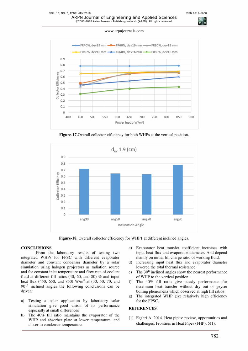
Overall collector efficiency at deferent heat
fluxes and fill ratios for both WHPs indicated in Figure-
17. The 40% FR shows highest efficiency than other
fillings and for both WHPs with steady value at deferent
heat input while the 60, 80% FR show lower collector
efficiency especially at low heat flux. The WHP1 is higher
efficiency than WHP2 for the same fill ratio and heat flux.
Figure-18 shows that the 30⁰ inclined angle has the nearest
efficiency to the vertical position.
Figure-4.Temperature distribution along the axil distance of WHP1at the vertical position.

VOL. 13, NO. 3, FEBRUARY 2018 ISSN 1819-6608
ARPN Journal of Engineering and Applied Sciences ©2006-2018 Asian Research Publishing Network (ARPN). All rights reserved.
www.arpnjournals.com
776
Figure-5. Temperature distribution for both WHPs at the vertical position and 40% FR.
Figure-6.Temperature distribution of WHP1 at deferent inclined angles.

VOL. 13, NO. 3, FEBRUARY 2018 ISSN 1819-6608
ARPN Journal of Engineering and Applied Sciences ©2006-2018 Asian Research Publishing Network (ARPN). All rights reserved.
www.arpnjournals.com
777
Figure-7.Absorbing plate temperatures at vertical position.
Figure-8.Plat temperature of WHP1 at different inclined angles.

VOL. 13, NO. 3, FEBRUARY 2018 ISSN 1819-6608
ARPN Journal of Engineering and Applied Sciences ©2006-2018 Asian Research Publishing Network (ARPN). All rights reserved.
www.arpnjournals.com
778
Figure-9.Evaporator heat transfer coefficient at different fills and input power
at the vertical position.
Figure-10.Evaporator heat transfer coefficient at different angles.

VOL. 13, NO. 3, FEBRUARY 2018 ISSN 1819-6608
ARPN Journal of Engineering and Applied Sciences ©2006-2018 Asian Research Publishing Network (ARPN). All rights reserved.
www.arpnjournals.com
779
Figure-11.Condenser heat transfer coefficient for both WHPs at the vertical position.
Figure-12.Total thermal resistance at the vertical position.

VOL. 13, NO. 3, FEBRUARY 2018 ISSN 1819-6608
ARPN Journal of Engineering and Applied Sciences ©2006-2018 Asian Research Publishing Network (ARPN). All rights reserved.
www.arpnjournals.com
780
Figure-13.Total thermal resistance at different inclined angles for WHP1.
Figure-14.Useful heat gain for WHP1 at the vertical position and 850W/m2 heat input.

VOL. 13, NO. 3, FEBRUARY 2018 ISSN 1819-6608
ARPN Journal of Engineering and Applied Sciences ©2006-2018 Asian Research Publishing Network (ARPN). All rights reserved.
www.arpnjournals.com
781
Figure-15. Useful heat gain for WHP1 at the vertical position and 450W/m2 heat input.
Figure-16.Useful heat gain for WHP1 at different inclined angles and 650W/m2 heat input.
VOL. 13, NO. 3, FEBRUARY 2018 ISSN 1819-6608
ARPN Journal of Engineering and Applied Sciences ©2006-2018 Asian Research Publishing Network (ARPN). All rights reserved.
www.arpnjournals.com
782
Figure-17.Overall collector efficiency for both WHPs at the vertical position.
Figure-18. Overall collector efficiency for WHP1 at different inclined angles.
CONCLUSIONS
From the laboratory results of testing two
integrated WHPs for FPSC with different evaporator
diameter and constant condenser diameter by a solar
simulation using halogen projectors as radiation source
and for constant inlet temperature and flow rate of coolant
fluid at different fill ratios (40, 60, and 80) % and input
heat flux (450, 650, and 850) W/m2 at (30, 50, 70, and
90)⁰ inclined angles the following conclusions can be
driven:
a) Testing a solar application by laboratory solar
simulation give good vision of its performance
especially at small differences
b) The 40% fill ratio maintains the evaporator of the
WHP and absorber plate at lower temperature, and
closer to condenser temperature.
c) Evaporator heat transfer coefficient increases with
input heat flux and evaporator diameter. And depend
mainly on initial fill charge ratio of working fluid.
d) Increasing input heat flux and evaporator diameter
lowered the total thermal resistance.
e) The 30⁰ inclined angles show the nearest performance
of WHP to the vertical position.
f) The 40% fill ratio give steady performance for
maximum heat transfer without dry out or geyser
boiling phenomena which observed at high fill ratios
g) The integrated WHP give relatively high efficiency
for the FPSC.
REFERENCES
[1] Faghri A. 2014. Heat pipes: review, opportunities and
challenges. Frontiers in Heat Pipes (FHP). 5(1).

VOL. 13, NO. 3, FEBRUARY 2018 ISSN 1819-6608
ARPN Journal of Engineering and Applied Sciences ©2006-2018 Asian Research Publishing Network (ARPN). All rights reserved.
www.arpnjournals.com
783
[2] Reay D., R. McGlen and P. Kew. 2013. Heat pipes:
theory, design and applications, ed. s. edition.
Butterworth-Heinemann.
[3] Noie S. 2005. Heat transfer characteristics of a two-
phase closed thermosyphon. Applied Thermal
Engineering. 25(4): 495-506.
[4] Noie S., M. Kalaei and M. Khoshnoodi. 2005.
Experimental investigation of boiling and
condensation heat transfer of a two phase closed
thermosyphon. International Journal of Engineering.
18(1): 37-43.
[5] Jafari Davoud., Filippeschi Sauro., Franco Alessandro
and Di Marco Paolo. 2017. Unsteady experimental
and numerical analysis of a two-phase closed
thermosyphon at different filling ratios. Experimental
Thermal and Fluid Science. 81: 164-174.
[6] Ma Limin., Shang Linlin., Zhong Dan. and Ji Zhongli.
2017. Experimental Performance of a Two-phase
Closed Thermosyphon Charged with Hydrocarbons
and Freon Refrigerants for Renewable Energy
Applications. Energy Procedia. 105: 5147-5152.
[7] Khairnasov S. and A. Naumova. 2016. Heat pipes
application to solar energy systems. Applied Solar
Energy. 52(1):47.
[8] Ordaz-Flores A., O. García-Valladares and V. Gómez.
2009. Evaluation of the Thermal Performance of a
Solar Water Heating Thermosyphon versus a Two-
Phase Closed Thermosyphon Using Different
Working Fluids. in Proceedings of ISES World
Congress 2007 (Vol. I-Vol. V). Springer.
[9] Azad E. 2012. Assessment of three types of heat pipe
solar collectors. Renewable and Sustainable Energy
Reviews. 16(5): 2833-2838.
[10] Duffie J.A. and W.A. Beckman. 2013. Solar
engineering of thermal processes. John Wiley & Sons.
[11] Kalogirou S.A. 2013. Solar energy engineering:
processes and systems. Academic Press.
[12] Eidan A.A., S.E. Najim and J.M. Jalil. 2016.
Experimental and numerical investigation of
thermosyphone performance in HVAC system
applications. Heat and Mass Transfer. 12(52): 2879-
2893.
[13] Jiao B., Qiu LM. Zhang XB and Zhang Y. 2008.
Investigation on the effect of filling ratio on the
steady-state heat transfer performance of a vertical
two-phase closed thermosyphon. Applied Thermal
Engineering. 28(11): 1417-1426.
[14] Khazaee I., R. Hosseini and S. Noie. 2010.
Experimental investigation of effective parameters
and correlation of geyser boiling in a two-phase
closed thermosyphon. Applied Thermal Engineering.
30(5): 406-412.
[15] LinTF, Lin WT., Tsay YL., Wu JC. and Shyu RJ.
1995. Experimental investigation of geyser boiling in
an annular two-phase closed thermosyphon.
International journal of heat and mass transfer. 38(2):
295-307.