experimental research on longitudinal steel bar bond...
TRANSCRIPT

Research ArticleExperimental Research on Longitudinal Steel BarBond Properties in Modified Recycled Aggregate ConcreteBeam-Column Interior Joint under Cyclic Loading
Jia-Li Fu,1,2 Bing-Kang Liu,1 and Jun-Wei Ma3
1School of Civil Engineering, Hefei University of Technology, Hefei 230009, China2School of Architecture and Civil Engineering, Anhui Polytechnic University, Wuhu 241000, China3School of Civil Engineering, Southeast University, Nanjing 210096, China
Correspondence should be addressed to Bing-Kang Liu; [email protected]
Received 9 December 2016; Accepted 15 March 2017; Published 3 May 2017
Academic Editor: Luigi Nicolais
Copyright © 2017 Jia-Li Fu et al.This is an open access article distributed under the Creative Commons Attribution License, whichpermits unrestricted use, distribution, and reproduction in any medium, provided the original work is properly cited.
Three recycled aggregate concrete (RAC) beam-column interior-joint specimens (including two modified recycled aggregateconcrete interior joints with replacement of fly ash ratio of 15%) were tested under cyclic loading in order to study the bond behaviorof the longitudinal steel bar at RAC joint. The tests obtained load-strain hysteresis curves of longitudinal bars. The relative bondstrength of longitudinal bar in characteristic stages was calculated. The test results indicated that the longitudinal steel bar in RACjoint is able to supply a stable bond stress both in the full crack stage and in the ultimate stage, meaning that the requirements ofstress transferring and displacement coordinating between RAC and reinforcements can be satisfied. The larger the diameter ofsteel bar, the more serious the bond strength degradation. The RAC with fly ash can improve the interface compactness and bondstrength of recycled aggregate in full crack stage. When beam-column interface of concrete compression zone reaches ultimatestrain, the compressive stress of the longitudinal reinforcement cannot be exerted. The bond stress of the steel bar cannot realizethe pull and compressive stress conversion in the length of the core area of the joint owing to the stress hysteresis of the compressionrebars.
1. Introduction
As a new green construction material, recycled aggregateconcrete has been of widespread concern in constructionindustry. It does not only solve the environment pollutioncaused by abandoned construction waste but also alleviatethe ecological pressure caused by natural aggregate mining.As a new structure, RAC structure has been systematicallyresearched in material properties and structural componentsby many scholars and obtained large amount of researchachievements. Existing research of RAC mainly focuses ontwo points: properties of RACmaterials and performances ofRAC members. Compressive strength [1–4], tensile strength[5–7], elastic modulus [8, 9], constitutive relationship [10–12], and durability [13–16] of RACmaterials have been widelyinvestigated. Flexural and shear performance of RAC beams[17–20], compressive performance of RAC column [21–24],
seismic performance of RAC beam-column joint [25–27],RAC shear wall [28], and RAC frame structure [29] have alsobeen reported in previous papers. However, there is little deepresearch on the steel bar bond properties of RAC structure,most of which are achieved by drawing test [30–34]. Existingresearch on bond properties under cyclic load only focusedon ordinary concrete structure but few pay attention to RACstructure [35].
Many of the earthquake damage and experimental testson ordinary concrete structures have indicated that, understrong earthquakes or cyclic load, the bond stress betweenconcrete and reinforcement steel bars will be decreased atthe joint, leading to the decrease of the joint stiffness andloss of the joint capacity, and finally the steel bar’s bond andanchor failure at the joint position usually caused the framestructural failure. From the above failure mode, it can beconcluded that better bond and anchor properties are a
HindawiAdvances in Materials Science and EngineeringVolume 2017, Article ID 9726989, 13 pageshttps://doi.org/10.1155/2017/9726989
2 Advances in Materials Science and Engineering
necessary condition to ensure a better cowork between RACand reinforced steel bars and steel bar bond properties area key factor to ensure RAC structures have well seismicproperties.
At present, the study of the bond behavior of steel barsin the RAC structure is mainly through the one-way pullouttest, the unidirectional drawing bond behavior of steel baris not applicable on seismic resistant structure, and steelbar-concrete bond behavior under cyclic load of ordinaryconcrete structures obtained was different from that of theRAC. In order to put the RAC structures into application inseismic areas, it is very necessary to carry out researches onsteel bar bond properties of RAC joint under cyclic load. Byexperiments of threeRACbeam-column interior joints undercyclic load, this paper studied the bond and slip propertiesof longitudinal steel bar crossing the RAC joint core area,and the research results can provide theory foundation forapplying RAC structure in earthquake regions.
2. Experiments Details
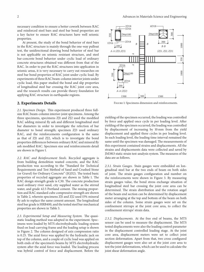
2.1. Specimen Design. This experiment produced three full-size RAC beam-column interior-joint specimens. Among thethree specimens, specimens ZJ1 and ZJ2 used the modifiedRAC adding mineral fly ash and different longitudinal steelbar diameters in order to investigate the refection of bardiameter to bond strength; specimen ZJ3 used ordinaryRAC, and the reinforcements configuration is the sameas that of ZJ1 and ZJ2, which is to investigate the bondproperties differences between ordinary RAC andmineral flyash modified RAC. Specimen size and reinforcements detailare shown in Figure 1.
2.2. RAC and Reinforcement Steels. Recycled aggregate isfrom building demolition wasted concrete, and the RACproduction was according to the “Standard for TechnicalRequirements and Test Method of Sand and Crushed Stone(or Gravel) for Ordinary Concrete” (JGJ52). The tested basicproperties of recycled aggregate are shown in Table 1. TheRAC design strength grade is C30. The concrete productionused ordinary river sand, city supplied water as the stirredwater, and grade 42.5 Portland cement. The mixing propor-tion and RAC standard cube compressive strength are shownin Table 2, wherein specimens ZJ1 and ZJ2 used 15% mineralfly ash to replace the same cement amount. The longitudinalsteel bar grade is HRB400, and the tested steel barmechanicalproperties are shown in Table 3.
2.3. Experimental Setup and Measuring System. The quasi-static loading method was adopted in the experiment. Spec-imens were loaded by MTS electrohydraulic loading systemfixed on load-carrying frame and the loading setup is shownin Figure 2. The column designed of axis compression ratiois 0.25. The axial force was applied by the hydraulic jack ontop of the column, and a couple of cyclic load was applied onboth ends of the specimen’s beams by MTS electrohydraulicsystem after the axial force was loaded. The loading processwas hybrid control of force and displacement. Before the
1D16 2D18
D6@100
A-A (ZJ2)
B-B
(ZJ1, ZJ2, ZJ3)
B
350
2D18
1000
A
350
B300
200
300
1000
350
1D16
1500 1500
300
200
A
D6@100
6D18
A-A (ZJ1,ZJ3)
D6@100
2D16
2D16
Figure 1: Specimens dimension and reinforcements.
yielding of the specimen occurred, the loadingwas controlledby force and applied once cycle in per loading level. Afteryielding of the specimen occurred, the loadingwas controlledby displacement of increasing by 10mm from the yielddisplacement and applied three cycles in per loading level.In each loading level, the loading time interval remained thesame until the specimen was damaged.Themeasurements ofthis experiment contained strains and displacements. All thestrains and displacements data were collected and saved byJM3813 static strain test-analysis system.Themeasures of thedata are as follows.
2.3.1. Strain Gauges. Stain gauges were embedded on lon-gitudinal steel bar at the two ends of beam on both sidesof joint. The strain gauges configuration and number onthe reinforcements were shown in Figure 3. By measuringstrain gauges value, the bond stress exchange situation oflongitudinal steel bar crossing the joint core area can bedetermined. The strain distribution and the rotation angelof the beam end section can be determined by displacementmeter arranging at the top and bottom of the beam on bothsides of the column. Some strain gauges were set on theconfinement stirrups at the joint core area, to collect theconfinement stirrups’ strain data.
2.3.2. Displacements. At the free end of beams, the MTSsensor can be used to measure the displacement. The MTStested displacements were also the loading control parameterin the displacement controlled loading stage. At the jointcore area, displacement meters were set to collect jointsection deformation. Apart from that, two cross configureddisplacement gauges were also set at the joint core area totest the joint deformations, which can be used to calculate thejoint shear deformation angle.

Advances in Materials Science and Engineering 3
Table 1: Basic performance indexes of the recycled aggregate.
Crash ratio (%) Water content ratio (%) Water absorption ratio (%) Apparent density (kg/m3) Micropower ratio (%)12 1.8 4.7 2627 3.3
Table 2: RAC mix properties and compressive strength.
Specimen Recycled aggregate ration (%)RAC mixing proportion
Cement : fly ash : sand : coarseaggregate : water
Cube compressive strength (MPa)
ZJ1, ZJ2 100 394 : 70 : 550 : 1169 : 226 30.2ZJ3 100 464 : 0 : 550 : 1169 : 226 32.2
Table 3: Measured mechanical properties of reinforcements.
Bar diameter (mm) Steel type Yield strength(𝑓𝑝𝑦/MPa)
Ultimate strength(𝑓𝑝𝑡/MPa)
Elastic modulus(𝐸/MPa) Elongation (%)
D16 Deformed bar 550.0 664.3 2.0 × 10⁵ 20.0%D18 Deformed bar 487.5 625.1 2.0 × 10⁵ 22.5%
MTS
Displacement transducers
MTS
Right beam
Planar hinge
Planar hinge Hydraulic jack
Left beam
Figure 2: Test setup.
LS1
LS5
1LS2
LS83
LS4
L S 6
2
LS3
4
LS7
Figure 3: Configuration of strain gauges.
3. Experimental Phenomenon and Analysis
3.1. Experimental Phenomenon. The shear failure happenedon joints core area of all the three specimens. The failureprocess can be divided into the initial crack stage, the fullcrack stage, the ultimate stage, and the failure stage, andthe damage and failure mode is familiar to that of ordinaryconcrete frame joint. In the process of the joint shear failure,a bending damage occurred at the joint connected beam endsection, in which the yielding of the longitudinal steel barcrossing beam end section and the sectional compressionconcrete reached its compressive strength. In the failure stage,there was no longitudinal crack along the steel bar andsplitting failure on concrete covers, indicating that the surfaceof longitudinal reinforcement keeps better bonding perfor-mance with concrete.The joints core area cracks and damageof all the three specimens in the initial crack stages, the fullcrack, the ultimate stage, and the failure stage are shown inFigure 4.
3.2. Load-Strain Hysteresis Curve. Bearing two antisymmet-rical loads on both free ends of beams, the same longitudinalsteel bar crossing joint area was tensioned at one joint sidewhile being compressed at the other joint side; the successivetension and compression transfer of longitudinal steel barmainly depend on the bond force on the surface of longitudi-nal steel bar through joint core area range. During the experi-mental test, load-strain hysteresis curves of longitudinal steelbar at the joint beam end section were recorded, and allthe load-strain hysteresis curves are shown in Figures 5, 6,and 7. Take the load-strain hysteresis curves of steel barsin specimen ZJ1 (Figure 5) as an example to illustrate itscharacteristics as follows:
(1) Strains from gauges LS1 and LS3 of specimen ZJ1have a linear relationship with load 𝑃 even when load𝑃 varies from positive to negative. Even in the full

4 Advances in Materials Science and Engineering
(a) ZJ1 in initial crack stage (b) ZJ1 in full crack stage (c) ZJ1 in ultimate stage (d) ZJ1 in failure stage
(e) ZJ2 in initial crack stage (f) ZJ2 in full crack stage (g) ZJ2 in ultimate stage (h) ZJ2 in failure stage
(i) ZJ3 in initial crack stage (j) ZJ3 in full crack stage (k) ZJ3 in ultimate stage (l) ZJ3 in failure stage
Figure 4: Damaged state of specimens in joints core area.
crack loading stage and the ultimate loading stage,the strains remain a stable relationship with load 𝑃,indicating no bond stress decrease.
(2) Strains from gauges LS2, LS4, LS5, and LS7 of spec-imen ZJ1 have a linear relationship with load 𝑃 inthe early positive-negative loading stage. When theloading process goes into the full crack stage, tensionstrain occurred on steel bar in compressive area,which indicates that the bond force is not enoughto ensure the successive tension-compression transferof longitudinal steel bar in joint core area. This alsoindicates that interface failure and slip occurred onthe steel bar-RAC surface. With the loading continu-ing, larger tension stress will occurred on compressivesteel bars and the bond stress decreasing will be moreserious.
(3) Sudden changes in tensile stress of longitudinal barsappear among the strains from gauges LS6 and LS8 ofspecimen ZJ1. This may be because a certain internalconcrete part was damaged, leading to bond stressfailure in one compressive loading process, and whenthe load transferred into tension load, a sudden slipoccurred on longitudinal steel bar.
3.3. Strain Distribution in Beam Joint Section. From thedisplacement meters at the top and button position of joint’s
beam section, the average tension strain and compressionstrain within a 250mm distance were obtained. Accordingto the rule that the sectional strain satisfied the plate sectionassumption, the strain distribution of the joint connectedbeam section can be obtained and Figure 8 showed the jointconnected beam sectional strain distribution of ZJ1.
In the test, two asymmetric forces of same value werekept applied on the free end of joint connected two beams.When loading into the failure stage, with the tension lon-gitudinal steel bar yielding, the compression strain of theconcrete at the sectional compression edge reached its failurelimit and the accumulated damage of compression concreteemerged which finally resulted in a flexural failure at thejoint connected beam end section.The section flexural failuresymbols are usually the yield of longitudinal steel bars and theconcrete reaching it ultimate compressive strength and theflexural capacity is determined by those symbols. Normally,the ultimate compressive strain value for ordinary concreteis 𝜀cu = 0.0033, while, for RAC, the ultimate compressivestrain value is slightly higher. Considering the concretecompression ultimate strain improvement from confinementsteel at the beam end, when the compressive strain value 𝜀cureached from 0.006 to 0.007, the concrete began to compressdamage, so the 𝜀cu value for RAC can be assumed to be2 times of the ordinary concrete value. Take yield strength𝑓𝑦 = 487.5N/mm2, elastic modulus 𝐸𝑠 = 2.0 × 10⁵N/mm2,

Advances in Materials Science and Engineering 5
−100−80−60−40−20
020406080
100
P(k
N)
0 500 1000 20001500−500
�휀 (×10−6)
(a) LS1
−100−80−60−40−20
020406080
100
P(k
N)
0 500 1000 20001500 2500−500
�휀 (×10−6)
(b) LS2
−100−80−60−40−20
020406080
100
P(k
N)
0 1000 2000 3000−1000−2000
�휀 (×10−6)
(c) LS3
−100−80−60−40−20
020406080
100
P(k
N)
0 500 1500 2500−500 1000 30002000
�휀 (×10−6)
(d) LS4
−100−80−60−40−20
020406080
100
P(k
N)
0 5001000 2000 300025001500−500
�휀 (×10−6)
(e) LS5
−100−80−60−40−20
020406080
100
P(k
N)
0 500 1000 2000 300025001500−500
�휀 (×10−6)
(f) LS6
−100−80−60−40−20
020406080
100
P(k
N)
0 500 1000 2000 300025001500−500
�휀 (×10−6)
(g) LS7
−100−80−60−40−20
020406080
100
P(k
N)
500 25001500 3500−500
�휀 (×10−6)
(h) LS8
Figure 5: Load-strain hysteresis curve of specimen ZJ1 longitudinal steel bar.
and yield strain 𝜀𝑠 = 0.00244 for D18 longitudinal steel bars.Take yield strength 𝑓𝑦 = 550.0N/mm2 and yield strain 𝜀𝑠 =0.00275 for D16 longitudinal steel bars.
Both the yield strains of D18 and D16 were less thanthe ultimate compressive strain of concrete, which meanstheoretically that the longitudinal steel bars yield first beforethe concrete damage. But the experimental results indicatedthat the actual compressive strain of longitudinal steel bar incompressive area was smaller than the corresponding sec-tional compressive strain value, whichmeans that the longitu-dinal reinforcement cannot completely work in compressionarea.
The compression longitudinal steel bar strain was notsynchronized with the concrete compression strain and acompression stress hysteresis performance existed. The rea-son that the compression stress hysteresis performance hap-pened is as follows.
Different degrees of failures and cracks exist at theinterfacial transition area between new and old mortar inRAC aggregate, causing a lower bond strength and weaker
mechanical bite strength, which lead to insufficient bondforce between concrete and steel bar. Finally, the tension andcompression stress on one longitudinal bar cannot be trans-formed in the length of the reinforcement crossing the corearea of the joint.
4. Bonding Mechanism under Cyclic Loading
4.1. Bonding Mechanism under Unidirectional Load. Bondstrength between deformed steel bar and concrete dependson three parts including cementation force, friction force,and mechanical bite force. Under unidirectional load, thecementation force starts to work first in initial loading stage.With load increasing, cementation destroyed and a relativeslip occurs between steel and concrete. At the same time,the oblique ribs on steel bar began to transmit pressureon concrete and generate cone wedging action, constitutingslipping resist force working together with frictional force.
Decompose the oblique rib transmitted force into thetransverse and longitudinal component forces shown in

6 Advances in Materials Science and Engineering
−80
−60
−40
−20
0
20
40
60
80P
(kN
)
0 1000 2000 3000 4000−1000
�휀 (×10−6)
(a) LS1
−80
−60
−40
−20
0
20
40
60
80
P(k
N)
0 500 1000 2000 300025001500−500
�휀 (×10−6)
(b) LS2
−80
−60
−40
−20
0
20
40
60
80
P(k
N)
0 20001000 40003000
�휀 (×10−6)
(c) LS3
−80
−60
−40
−20
0
20
40
60
80
P(k
N)
0 1000 2000 3000 4000−1000
�휀 (×10−6)
(d) LS4
−80
−60
−40
−20
0
20
40
60
80
P(k
N)
0 1000 2000 3000−1000
�휀 (×10−6)
(e) LS5
−80
−60
−40
−20
0
20
40
60
80
P(k
N)
0 500 1000 2000 300025001500−500
�휀 (×10−6)
(f) LS6
−80
−60
−40
−20
0
20
40
60
80
P(k
N)
0 1000 2000 40003000−1000
�휀 (×10−6)
(g) LS7
−80
−60
−40
−20
0
20
40
60
80
P(k
N)
0 500 1000 2000 300025001500−500
�휀 (×10−6)
(h) LS8
Figure 6: Load-strain hysteresis curve of specimen ZJ2 longitudinal steel bar.
Figure 9(a). The transverse component force causes a ringtensile stress 𝜎𝜃 on concrete around steel bar and syn-chronously the longitudinal component force causes a lon-gitudinal tensile stress 𝜎𝑧 on concrete. The combinationof these two forces makes concrete in a complex three-dimensional stress state. The ring tensile stress 𝜎𝜃 causesinternal radial cracks, and usually the bond stress, when theconcrete protective layer cracks, was taken as a critical stateof bond strength determination [36].
4.2. Bonding Mechanism under Cyclic Load. The cyclic loadleads to an exchanging bidirectional stress on the joint steelbars and the bond properties between steel and concretewill be reduced dramatically compared to that under uni-directional load. As the cyclic times increase, the bondstress keeps decreasing and finally stabilizes to a balance.The load-bond strength curves under cyclic loading showedobvious hysteretic characteristics. In the positive loadingstage, one side of the transverse steel bar ribs presses and leadsirreversible deformation on concrete, while cracks and gaps
exist on the other transverse ribs side caused by tension stress.When converting into the negative loading stage, the steel barribs slip after steel ribs-concrete surface friction is overcome,and, with the negative load increasing, the steel ribs beginto press the other concrete side. In this positive-negativeload conversion process, the repeated loads on longitudinalsteel bars do not only lead to a reduction of friction andmechanical bite action but also cause the “boundary layer”concrete surrounding steel bar to be damaged, resulting inbondproperties deterioration (Figure 9(b)). At the same time,the cyclic slips exist in both loading directions, so that thefriction andmechanical bite action between steel ribs and theconcrete aggregate will be further reduced compared to thatunder unidirectional load.
The longitudinal bar on both sides of joint is subjectedto the alternating action of tension and pressure under cyclicloading; with the increase of the number of cycles, the bondstress decreases and finally tends to be stable. The bondbehavior between steel bar and concrete is obvious degra-dation compared to that one under unidirectional load. The

Advances in Materials Science and Engineering 7
−80
−60
−40
−20
0
20
40
60
80P
(kN
)
0 1000 2000 3000−1000
�휀 (×10−6)
(a) LS1
0 500 1000 20001500 2500−500
�휀 (×10−6)
−80
−60
−40
−20
0
20
40
60
80
P(k
N)
(b) LS2
500 35001500 2500−500
�휀 (×10−6)
−80
−60
−40
−20
0
20
40
60
80
P(k
N)
(c) LS3
0 500 1000 20001500 2500−500
�휀 (×10−6)
−80
−60
−40
−20
0
20
40
60
80
P(k
N)
(d) LS4
0 500 1000 2000 300025001500−500
�휀 (×10−6)
−80
−60
−40
−20
0
20
40
60
80
P(k
N)
(e) LS5
−80
−60
−40
−20
0
20
40
60
80
P(k
N)
0 500 1000 20001500 2500−500
�휀 (×10−6)
(f) LS6
−80
−60
−40
−20
0
20
40
60
80
P(k
N)
0 1000 2000 3000−1000
�휀 (×10−6)
(g) LS7
−80
−60
−40
−20
0
20
40
60
80
P(k
N)
0 500 1000 20001500−500
�휀 (×10−6)
(h) LS8
Figure 7: Load-strain hysteresis curve of specimen ZJ3 longitudinal steel bar.
bond stress degradation degree relates to the loading process,the cyclic times, the lateral confinement effect, and someother factors. In the several early loading cycles, the averagebond stress was low, and the cementing force and frictionforce proportion was large in the bond stress components.In the full crack loading stage, the transverse steel ribswere compressed and the mechanical bite action worked.In the ultimate loading stage, the “boundary layer” concretesurrounding steel bars was damaged, and the bonding slipshappened and caused the steel bond stress to decrease. In thefailure loading stage, significant steel bar bond slip happenedon and the bond stress decreased rapidly. As a very stronglateral confinement was configured in the joint core area,no slip damage or steel bar pull out damage appeared. Theexperimental results indicate that more cyclic loading timesor a larger controlled load (or controlled displacement) isrelated to more serious damage on the steel bar “boundarylayer” concrete, and smaller friction and mechanical biteforce along steel bar, and higher bond strength reduction.
5. Bond Stress
5.1. Load-Bond Stress Hysteresis Curve. The bond force mag-nitude can be measured by the variation of stress in steel bar[36]. The average bond stress in longitudinal steel bar can becalculated from the strain difference of twomeasure points onsame longitudinal steel bar. The average bond stress betweenthe two measure points can be calculated by the followingformula:
𝜏 =𝐸𝑠 (𝜀2 − 𝜀1) 𝑑
4𝑙, (1)
where 𝑙 is the distance of two measure points, taken 300mmin this experiment. 𝑑 is the measured steel bar diameter. 𝐸𝑠is the elastic modulus of steel bar. 𝜀1, 𝜀2 are the strains ofmeasured points, considering the yield strength of steel andstrain gauge working range, taking 2750 as the value of 𝜀1 and𝜀2 when they are beyond 2750 for the D16 steel bar and taking

8 Advances in Materials Science and Engineering
(a) Left beam on positive loading (b) Right beam on negative loading
(c) Left beam on negative loading (d) Right beam on positive loading
−15 −10 −5 0 5 10 15 20 25 30
0 5 201510 25 30−5−10−15
�휀 (×10−3)0 5 201510 25−5−10−15
�휀 (×10−3)
−15 −10 −5 0 5 10 15 20 25
−20 −10 −5 0 5 10 15 20
0 5 1510 20−5−10−20
−15
−15
�휀 (×10−3)0 5 201510 25−5−10−15
�휀 (×10−3)
−15 −10 −5 0 5 10 15 20 25
Figure 8: Beam section strain distribution on two sides of column of specimen ZJ1.
cd
c
Diagonal cracks Radial crack
Friction force
Compress force
�휃
�휎z
�휎�휃
(a) Bonding mechanism under unidirectional load
FB
E
1
A
D
C
O
compress area
Gap closed
Gap opened
Internal cracks
Internal cracksCompress area
Stress direction
s
�휏
sr
(b) Bonding mechanism under cyclic load
Figure 9: Bonding mechanism of longitudinal steel bar.
2440 as the value of 𝜀1, 𝜀2 when they are beyond 2440 for theD18 steel bar.
Strain gauges were set on all of the four longitudinal steelbars on the two sides of the joint at beam ends. The straingauges and longitudinal steel bars relationship are as follows:gauges LS1 and LS2 to steel bar No. 1, gauges LS3 and LS4 tosteel bar No. 2, gauges LS5 and LS6 to steel bar No. 3, andgauges LS7 and LS8 to steel bar No. 1.
Taking strains of two gauge measure positions on thesame longitudinal steel bar and same loading cycle intoformula (1), the corresponding average bond stress can beobtained. Taking ZJ1, for example, taking strain data in load-strain hysteresis curves shown in Figures 5(a) and 5(b) intoformula (1) synchronous overlap, and afterward adding dataobtained from formula (1) into the curves, the average bondstress data and the load-bond stress hysteresis curves of

Advances in Materials Science and Engineering 9
0
2
4
6
8
10
�휏(M
Pa)
20 60 100−20−60−100
P (kN)
(a) Steel bar No. 1 in ZJ1
0
2
4
6
8
10
12
14
�휏(M
Pa)
−60 −20 20 60 100−100
P (kN)
(b) Steel bar No. 2 in ZJ1
0
2
4
6
8
10
�휏(M
Pa)
−60 −20 20 60 100−100
P (kN)
(c) Steel bar No. 3 in ZJ1
0
2
4
6
8
10
�휏(M
Pa)
−60 −20 20 60 100−100
P (kN)
(d) Steel bar No. 4 in ZJ1
Figure 10: Load-bond stress hysteresis curve of tested longitudinal steel bars in ZJ1 specimen.
longitudinal steel bar can be obtained, shown in Figure 10(a).By the same way, the average bond stress hysteresis curve ofall the tested longitudinal steel bars in specimens ZJ1, ZJ2, andZJ3 can be obtained.
Curves in Figure 10 show the load-bond stress hysteresiscurve of steel bars in specimen ZJ1.The four curves indicatedthe following:
(1) In the initial loading stage, the average bond stress isvery low, and the bond stress distributions in positiveloading and negative loading are symmetrical.
(2) In the full crack stage, the longitudinal steel barsat the compression area of beam end section showtension stress, indicating that the bond stress began todecrease. The positive and negative load-bond stresscurves of most specimens are asymmetric, but allspecimens maintain relative stable bond strength.
(3) Continue loading into the ultimate stage. After thebond stress reached its peak value, the increasingdegree in the load-bond stress curves begins todecrease and the average bond stress begins to reducewhich means that slips occur on longitudinal steelbars.
(4) In the failure stage, bond slips happen on part of thelongitudinal steel bars and the bond stress of thosesteel bars decreases rapidly.
5.2. Average Bond Stress. In order to quantitatively study thedevelopment and failure process of bond stress on longitu-dinal steel bar in the three specimens, the correspondingaverage bond stresses of longitudinal steel bars in the full
crack stage, the ultimate stage, and the failure stage are shown,respectively, in Table 4, concluded as follows:
(1) The bond stresses on longitudinal steel bar in thefull crack stage and the ultimate stage are relativelystable.The average bond strength ranges from 6.512 to7.439MPa, and the relative bond strength ratio rangesfrom 0.208 to 0.246.
(2) In the failure stage, the bond strength decreasesrapidly. The average bond strength ranges from 3.723to 4.505MPa, and the relative bond strength ratioranges from 0.116 to 0.150.
Table 5 shows the statistic results of longitudinal steelbar bond stress at each stage obtained from experimentalresults shown in Table 4. For the sake of intuitive comparison,histograms are shown in Figure 11, which shows the relativebond stress of different steel bar diameters in commonand modified RAC. And, from Figure 11, the followingconclusions can be obtained:
(1) For the modified RAC specimens ZJ1 and ZJ2, therelative bond strength of the D18 longitudinal steelbar in the full crack stage is 96.3% of the D16 steel barrelative bond strength when other conditions remainsame. In the failure stage, the relative bond strengthratio of the two specimens is 87.8%.
(2) When the steel bar diameter is larger, the loss ofbond strength is more serious. This is similar withthe effect of steel bar diameter to bond strength incommon concrete. This is also the reason why “Codefor Seismic Design of Buildings (GB 50011)” limits the

10 Advances in Materials Science and Engineering
Table 4: Bond stress on longitudinal steel bar crossing joint in each of the loading stages.
Specimen Steel bar number anddiameter Loading direction Full-section crack stage Ultimate stage Failure stage
𝜏𝑦/MPa 𝜏𝑦/𝑓cu 𝜏𝑢/MPa 𝜏𝑢/𝑓cu 𝜏𝑝/MPa 𝜏𝑝/𝑓cu
ZJ-1
No. 1 D18 Positive 4.491 0.149 3.255 0.108 2.148 0.071Negative 8.066 0.267 8.510 0.282 5.839 0.199
No. 2 D18 Positive 6.104 0.202 6.978 0.231 5.786 0.192Negative 12.387 0.410 13.029 0.431 8.232 0.273
No. 3 D18 Positive 5.874 0.195 1.734 0.057 0.126 0.004Negative 7.891 0.261 8.087 0.268 5.931 0.196
No. 4 D18 Positive 6.299 0.206 6.519 0.216 4.102 0.136Negative 4.719 0.156 3.980 0.132 3.872 0.128
ZJ-2
No. 1 D16 Positive 6.968 0.231 7.210 0.239 4.983 0.165Negative 6.932 0.230 7.220 0.239 4.532 0.150
No. 2 D16 Positive 7.909 0.262 8.646 0.286 4.565 0.151Negative 8.149 0.270 9.342 0.309 6.235 0.206
No. 3 D16 Positive 7.751 0.257 7.506 0.249 3.230 0.107Negative 5.208 0.172 6.010 0.199 1.342 0.044
No. 4 D16 Positive 8.472 0.281 8.735 0.289 2.987 0.099Negative 6.554 0.217 4.843 0.160 3.373 0.112
ZJ-3
No. 1 D18 Positive 8.004 0.249 9.073 0.282 7.014 0.218Negative 3.101 0.096 1.776 0.055 0.538 0.017
No. 2 D18 Positive 8.478 0.263 10.224 0.318 7.642 0.237Negative 6.206 0.193 7.345 0.228 1.029 0.032
No. 3 D18 Positive 8.085 0.251 8.471 0.263 4.081 0.127Negative 7.893 0.245 7.935 0.246 2.022 0.063
No. 4 D18 Positive 6.420 0.199 1.482 0.046 0.654 0.020Negative 6.759 0.210 8.934 0.277 6.800 0.211
16 mm diameter18 mm diameter
Full-sectioncrack stage
0
0.05
0.1
0.15
0.2
0.25
0.3
Rela
tive b
ond
stren
gth�훽
Ultimate stage Failure stage
(a) Relative bond strengths with different steel bar diameters
Modified recycled concreteOrdinary recycled concrete
Ultimate stage Failure stageFull-sectioncrack stage
0
0.05
0.1
0.15
0.2
0.25
0.3
Rela
tive b
ond
stren
gth�훽
(b) Relative bond strengths of modified and ordinary RAC
Figure 11: Relative bond stresses of longitudinal steel bar.
longitudinal steel bar diameter crossing the interiorjoints of middle column in frame.
(3) Comparing the average bond stress results in eachstage of common RAC specimen ZJ3 to that ofmodified RAC specimen ZJ1, the relative longitudinal
steel bar bond strength of ZJ1 is 1.085 times of that ofZJ3, and the ultimate relative bond strength of ZJ1 is1.010 times of that of ZJ3.
(4) By adding mineral fly ash in common RAC, themineral fly ash can directly fill the interface pores of

Advances in Materials Science and Engineering 11
Table5:Statisticresults
ofbo
ndstr
esso
nlong
itudinalsteelbarc
rossingjointineach
loadingsta
ge.
Specim
enSteeld
iameter
Averageb
ondstr
ength
(MPa)
Varia
nce
𝜎
Varia
tion
coeffi
cient
𝐶V
Relativ
ebon
dstr
ength𝛽
𝜏 𝑚/𝑓
cu
ZJ1and
ZJ2
𝛽𝐷18/𝛽𝐷16
ZJ1and
ZJ3
𝛽𝑚/𝛽𝑜
Fullcracksta
geZJ1
D18
6.979
2.372
0.340
0.231
0.963
1.085
ZJ2
D16
7.243
0.989
0.137
0.240
ZJ3
D18
6.868
1.630
0.237
0.213
Ultimates
tage
ZJ1
D18
6.512
3.336
0.512
0.216
0.878
1.010
ZJ2
D16
7.439
1.398
0.188
0.246
ZJ3
D18
6.905
3.148
0.456
0.214
Failu
resta
geZJ1
D18
4.505
2.362
0.524
0.150
1.162
1.293
ZJ2
D16
3.906
1.395
0.357
0.129
ZJ3
D18
3.723
2.861
0.769
0.116
∗𝛽𝑚isforthe
mineralfly
ashmod
ified
RACand𝛽𝑜isforthe
ordinary
RAC.
∗𝛽𝐷18isforthe
steeldiam
eter
18mm
and𝛽𝐷16isforthe
steeldiam
eter
16mm.

12 Advances in Materials Science and Engineering
recycled aggregate, bond microcracks, and improvethe interface compactness and bonding reaction, as aresult improving the bond and friction between steelbars and concrete.
(5) In the full crack stage, the portion of cementing forceand frictional force in bond strength is large. Andalso, in this stage, the bond stress of mineral fly ashmodified RAC is increased by 8.5% of ordinary RACbond stress.
(6) In the ultimate stage, the bond strength of the longitu-dinal steel bar mainly depends on themechanical biteforce, and the using ofmineral fly ash can increase thebond stress by 1.0% of ordinary RAC bond stress.
6. Conclusions
The distribution law of the bond stress on longitudinal steelbar crossing joint core area was discussed, and the followingconclusions were obtained:
(1) The tests indicated that the bearing capacity, failuremode, and seismic performance of the modifiedrecycled concrete interior joint with fly ash equivalentreplacement rate of 15% had few differences fromthose of conventional recycled concrete. The brittle-ness in the core area of the RAC concrete specimenswith fly ash is slightly more obvious than that of RACconcrete, and the ductility is slightly less than that one.
(2) The mineral fly ash added in RAC can directly fill theinterface pores of recycled aggregate, bond microc-racks, and can enhance the interface compactness andbonding reaction and as a result improves the bondand friction between steel bars and concrete. In thefull crack stage, the bond stress of mineral fly ashmodified RAC is increased by 8.5% of the ordinaryRAC bond stress. And, in the ultimate stage, the usingof mineral fly ash increases the bond stress by 1.0% ofordinary RAC bond stress.
(3) The bond stresses of longitudinal steel bars in thefull crack stage and the ultimate stage are relativelystable. The average bond strength ranges from 6.512to 7.439MPa, and the relative bond strength rangesfrom 0.208 to 0.246. In the failure stage, the bondstrength decreases rapidly.The average bond strengthranges from 3.723 to 4.505MPa, and the relative bondstrength ranges from 0.116 to 0.150. Taking bondstrength in full crack stage as the design condition,the bond strength of longitudinal steel bars in RACcan satisfy the requirements of stress transfer, defor-mation coordination between steel bars and concrete,and safety reserve.
(4) At the same conditions, the relative bond strength infull stage of D18 longitudinal steel bar is 96.3% of D16longitudinal steel bar relative bond strength and therelative bond strength ratio is 87.8%, indicating thatthe larger the steel bar diameter is, the more seriousthe strength loss is, showing the same influence in
ordinary concrete structure. It is suggested that whensatisfying design requirements, the diameter of steelbar crossing the interior joint of middle column inframe should be small.
(5) A compression steel stress hysteresis phenomenonexisted in the experiment. When the compressionsteel stress hysteresis phenomenon occurred, the con-crete compressive strain in beam end section reachedits failure value, while the steel compression strainvalue was far more less than that of the correspondingcompressive strain value according to the sectionassumption, indicating that the compressive steelcannot be fully exerted. The reason for this stresshysteresis is that the bond stress between the concreteand the steel bar is not enough so that the tensionand compression stress on one longitudinal bar cannot be transformed in the length of the reinforcementcrossing the core area of the joint.
(6) In this experiment, the dense stirrups at the beamend were confined and axial pressure was appliedon the columns, which would improve the bondperformance of the longitudinal steel bars crossingjoints. Because of the limited number of specimens,the considered parameters relating to bond propertiesare also limited. So the further studies should considerthose research deficiencies above.
Conflicts of Interest
The authors declare that they have no conflicts of interest.
Acknowledgments
This work was financially supported by Science and Tech-nology Project of Housing and Urban-Rural Development ofChina (Grant 2013-K4-46) and Higher Education PromotionProject of Anhui Province, China (Grant TSKJ2015B05).
References
[1] T. C. Hansen and H. Narud, “Strength of recycled concretemade from crushed concrete coarse aggregate,” Concrete Inter-national, vol. 5, no. 1, pp. 79–83, 1983.
[2] M. Tavakoli and P. Soroushian, “Strengths of recycled aggregateconcrete made using field-demolished concrete as aggregate,”ACI Materials Journal, vol. 93, no. 2, pp. 182–190, 1996.
[3] R. Sri Ravindrajah, Y. H. Loo, and C. T. Tam, “Strength evalu-ation of recycled-aggregate concrete by in-situ tests,” Materialsand Structures, vol. 21, no. 4, pp. 289–295, 1988.
[4] J. Z. Xiao, J. B. Li, Z. P. Sun, and X. M. Hao, “Study on compres-sive strength of recycled aggregate concrete,” Journal of TongjiUniversity (Natural Science Edition), vol. 32, no. 12, pp. 1558–1561, 2004 (Chinese).
[5] G.-F. Peng, Y.-Z. Huang, H.-S.Wang, J.-F. Zhang, andQ.-B. Liu,“Mechanical properties of recycled aggregate concrete at lowandhighwater/binder ratios,”Advances inMaterials Science andEngineering, vol. 2013, Article ID 842929, 6 pages, 2013.
Advances in Materials Science and Engineering 13
[6] J. Z. Xiao and Y. Lan, “Investigation on the tensile behavior ofrecycled aggregate concrete,” Journal of Building Materials, vol.9, no. 2, pp. 154–158, 2006 (Chinese).
[7] X. Teng, Y. B. Lu, X. Chen, S. S. Yu, and X. Q. Jiang, “Tests fordynamic tensile of recycled aggregate concrete,” Journal ofVibration and Shock, vol. 35, no. 9, pp. 43–51, 2016 (Chinese).
[8] Q. Hu, C. Song, and C. Y. Zou, “Experimental research on themechanical properties of recycled concrete,” Journal of HarbinInstitute of Technology, vol. 41, no. 4, pp. 33–36, 2009 (Chinese).
[9] Z. H. Duan, S. C. Kou, and C. S. Poon, “Using artificial neuralnetworks for predicting the elastic modulus of recycled aggre-gate concrete,” Construction & Building Materials, vol. 44, no. 7,pp. 524–532, 2014.
[10] J. Z. Xiao, “Experimental investigation on complete stress-straincurve of recycled concrete under uniaxial loading,” Journal ofTongji University, vol. 35, no. 11, pp. 1445–1454, 2007 (Chinese).
[11] G.-F. Belen, M.-A. Fernando, and C. L. Diego, “Stress-strainrelationship in axial compression for concrete using recycledsaturated coarse aggregate,” Construction & Building Materials,vol. 25, no. 5, pp. 2335–2342, 2011.
[12] T. Du, W. Wang, Z. Liu, H. Lin, and T. Guo, “The completestress-strain curve of recycled aggregate concrete under uniax-ial compression loading,” Journal Wuhan University of Technol-ogy, Materials Science Edition, vol. 25, no. 5, pp. 862–867, 2010(Chinese).
[13] F. T. Olorunsogo and N. Padayachee, “Performance of recycledaggregate concrete monitored by durability indexes,” Cement &Concrete Research, vol. 32, no. 2, pp. 179–185, 2002.
[14] A. Gokce, S. Nagataki, and T. Saeki, “Freezing and thawingresistance of air entrained concrete incorporating recycledcoarse aggregate: the role of air content in demolished concrete,”Cement & Concrete Research, vol. 34, no. 5, pp. 799–806, 2004.
[15] J. S. Ryu, “An experimental study on the effect of recycled aggre-gate on concrete properties,”Magazine of Concrete Research, vol.54, no. 1, pp. 7–12, 2002.
[16] V. W. Y. Tam, X. F. Gao, and C. M. Tam, “Microstructuralanalysis of recycled concrete produced from two-stage mixingapproach,” Cement & Concrete Research, vol. 35, no. 6, pp. 1195–1203, 2005.
[17] G. F. Belen and M. A. Fernando, “Shear strength of recycledconcrete beams,” Construction & Building Materials, vol. 21, no.4, pp. 887–893, 2007.
[18] G. F. Belen, M. A. Fernando, and M. L. Isabel, “Structural shearbehaviour of recycled concrete with silica fume,” Construction& Building Materials, vol. 23, no. 11, pp. 3406–3410, 2009.
[19] W. C. Choi and H. D. Yun, “Long-term deflection and flexuralbehaviour of reinforced concrete beams with recycled aggre-gate,”Materials & Design, vol. 51, no. 5, pp. 742–750, 2013.
[20] M. Arezoumandi, J. S. Volz, andK.H. Khayat, “An experimentalstudy on shear strength of reinforced concrete beams with 100%recycled concrete aggregate,”Construction&BuildingMaterials,vol. 88, no. 2, pp. 612–620, 2015.
[21] Y.-F. Yang and L.-H. Han, “Experimental behaviour of recycledaggregate concrete filled steel tubular columns,” Journal ofConstructional Steel Research, vol. 62, no. 12, pp. 1310–1324,2006.
[22] W.-C. Choi and H.-D. Yun, “Compressive behavior of rein-forced concrete columnswith recycled aggregate under uniaxialloading,” Engineering Structures, vol. 41, pp. 285–293, 2012.
[23] Y.-F. Yang and G.-L. Ma, “Experimental behaviour of recycledaggregate concrete filled stainless steel tube stub columns andbeams,”Thin-Walled Structures, vol. 66, pp. 62–75, 2013.
[24] J. Xiao, Y. Huang, and Z. Sun, “Seismic behavior of recycledaggregate concrete filled steel and glass fiber reinforced plastictube columns,”Advances in Structural Engineering, vol. 17, no. 5,pp. 693–707, 2014.
[25] V. Corinaldesi, V. Letelier, and G. Moriconi, “Behaviour ofbeam-column jointsmade of recycled-aggregate concrete undercyclic loading,” Construction & Building Materials, vol. 25, no.4, pp. 1877–1882, 2011.
[26] B. K. Liu, L. H. Chen, A. Zhou, Y. Zeng, and L. Fu, “Experi-mental study on seismic behavior of recycled aggregate concretebeam-column interior-joints,” Journal of Building Structures,vol. 32, no. 11, pp. 109–115, 2011 (Chinese).
[27] V. C. Letelier Gonzalez and G. Moriconi, “The influence ofrecycled concrete aggregates on the behavior of beam-columnjoints under cyclic loading,” Engineering Structures, vol. 60, pp.148–154, 2014.
[28] J. Zhang, W. Cao, S. Meng, C. Yu, and H. Dong, “Shakingtable experimental study of recycled concrete frame-shear wallstructures,” Earthquake Engineering and Engineering Vibration,vol. 13, no. 2, pp. 257–267, 2014 (Chinese).
[29] J. Xiao, Y. Sun, and H. Falkner, “Seismic performance offrame structures with recycled aggregate concrete,” EngineeringStructures, vol. 28, no. 1, pp. 1–8, 2006.
[30] L. Butler, J. S. West, and S. L. Tighe, “The effect of recycled con-crete aggregate properties on the bond strength between RCAconcrete and steel reinforcement,”Cement & Concrete Research,vol. 41, no. 10, pp. 1037–1049, 2011.
[31] B. Wang, G. L. Bai, H. J. Dai, and S. H. Wu, “Experimental andmechanical analysis of bond-slip performance between recycledconcrete and rebar,” Engineering Mechanics, vol. 30, no. 10, pp.54–64, 2013 (Chinese).
[32] Q. Hu, W. W. Chen, and C. Y. Zhou, “Experimental study onbonding properties of recycled concrete,” Journal of HarbinInstitute of Technology, vol. 42, no. 12, pp. 1849–1854, 2010(Chinese).
[33] J. Z. Xiao and B. Lei, “Experimental study on bond behaviorbetween corroded steel bars and recycled concrete,” Journal ofBuilding Structures, vol. 32, no. 1, pp. 58–62, 2011 (Chinese).
[34] M. Guerra, F. Ceia, J. D. Brito, and E. Julio, “Anchorage of steelrebars to recycled aggregates concrete,”Construction& BuildingMaterials, vol. 72, pp. 113–123, 2014.
[35] W. X. Zhu and B. K. Liu, “Experimental study of the bondbehavior of eccentric beam-column joints under cyclic reverseloading,” Journal of Hefei University of Technology, vol. 26, no. 5,pp. 966–970, 2003 (Chinese).
[36] J. R. Tang, Seismic Resistance of Joints in Reinforced ConcreteFrames, Southeast University Press, Nanjing, China, 1989 (Chi-nese).

Submit your manuscripts athttps://www.hindawi.com
ScientificaHindawi Publishing Corporationhttp://www.hindawi.com Volume 2014
CorrosionInternational Journal of
Hindawi Publishing Corporationhttp://www.hindawi.com Volume 2014
Polymer ScienceInternational Journal of
Hindawi Publishing Corporationhttp://www.hindawi.com Volume 2014
Hindawi Publishing Corporationhttp://www.hindawi.com Volume 2014
CeramicsJournal of
Hindawi Publishing Corporationhttp://www.hindawi.com Volume 2014
CompositesJournal of
NanoparticlesJournal of
Hindawi Publishing Corporationhttp://www.hindawi.com Volume 2014
Hindawi Publishing Corporationhttp://www.hindawi.com Volume 2014
International Journal of
Biomaterials
Hindawi Publishing Corporationhttp://www.hindawi.com Volume 2014
NanoscienceJournal of
TextilesHindawi Publishing Corporation http://www.hindawi.com Volume 2014
Journal of
NanotechnologyHindawi Publishing Corporationhttp://www.hindawi.com Volume 2014
Journal of
CrystallographyJournal of
Hindawi Publishing Corporationhttp://www.hindawi.com Volume 2014
The Scientific World JournalHindawi Publishing Corporation http://www.hindawi.com Volume 2014
Hindawi Publishing Corporationhttp://www.hindawi.com Volume 2014
CoatingsJournal of
Advances in
Materials Science and EngineeringHindawi Publishing Corporationhttp://www.hindawi.com Volume 2014
Smart Materials Research
Hindawi Publishing Corporationhttp://www.hindawi.com Volume 2014
Hindawi Publishing Corporationhttp://www.hindawi.com Volume 2014
MetallurgyJournal of
Hindawi Publishing Corporationhttp://www.hindawi.com Volume 2014
BioMed Research International
MaterialsJournal of
Hindawi Publishing Corporationhttp://www.hindawi.com Volume 2014