experimental results and wear predictions of petal tools that freely rotate
TRANSCRIPT

Experimental results and wear predictions of petaltools that freely rotate
Alberto Cordero-Dávila, Víctor Cabrera-Peláez, Jorge Cuautle-Cortés,Jorge González-García, Carlos Robledo-Sánchez, and Nazario Bautista-Elivar
It is difficult to calculate the wear produced by free-pinned tools because their angular movement is notentirely predictable. We analyze the wear produced with free-pinned ring tools, using both simulationsand experiments. We conclude that the wear of an incomplete ring is directly proportional to the ring’sangular size, independently of the mean radius of the ring. We present an algorithm for calculation of thewear produced by free-pinned petal tools, as they can be considered a linear combination of incompletefree-pinned ring tools. Finally, we apply this result to the enhancement of a defective flat surface and tomaking a concave spheric surface. © 2005 Optical Society of America
OCIS codes: 220.0220, 220.4610, 220.5450.
1. Introduction
We begin by using the Preston model1 to calculatethe wear2 produced by petal tools, as was first pro-posed by Golovanova et al.3 for manufacturingaspheric convex optical surfaces of revolution. Ly-syannyy and Tsesnek4 applied this method to theshaping aspheric concave parabolic surfaces of rev-olution with a central aperture. Later, Lysyanny etal.5 presented a procedure for iterative correction ofthe form of a petal tool for polishing. Unfortunately,the calculations were based on tools that do notoscillate or rotate, so the authors reported the pres-ence of concentric scratches on the surfaces pro-duced. Brown6,7 proposed a method for calculationof wear for petal tools that rotate and oscillate. Heinitially calculated a set of functions that define thewear patterns produced by several oscillating ringsof different mean radii during a unitary time. In allcases the oscillating amplitude was equal to thewidth of the ring. Then, having computed the ringwear pattern, he could conceivably take a ratio be-tween the desired wear and the unit time wear,operate the ring for the time predicted by the ratio,
then make up another ring, and repeat the processas needed. He calculated with an approximate for-mula the time that each ring acts in the process toproduce the desired wear and, finally, to preventindependent operation of the rings he translatedtime into angular coverage. Chang and Lee8 per-formed simulations for the design of the petal tools,considering successive linear approximations. Inthe two papers that describe petal tools rotatingand oscillating,6,8 no experimental results were re-ported.
To search for a way to prevent scratches, in thispaper we concentrate on free-pinned tools that canoscillate (tools that oscillate and freely rotate abouttheir mass centers). We show that, under these con-ditions, the wear produced by a two-ring tool (onewhose rings are placed over the same pad) is identicalfor each ring and that the wear produced by an in-complete ring is directly proportional to the angle ofthe ring. We present an interactive algorithm for cal-culation of the wear of the petal tools that is useful forcorrecting any surface of revolution with a commer-cial polishing machine. We begin with a normalizedgraph of the required wear; in addition we proposethe angular size of a set of incomplete rings thatdefine the petal tool, and we calculate a normalizedgraph of the wear achieved with the proposed algo-rithm. The normalized graphs of the predicted andthe desired wear are then superposed. From a com-parison of the excess or deficit wear, the angle sizes ofthe rings are modified, and thus the petal tool shapeis redefined. We conclude this paper by showing ex-perimental results obtained in the enhancement of a
The authors are with Taller de Óptica de la Facultad de CienciasFísico-Matemáticas, Benemérita Universidad Autónoma dePuebla, Apartado Postal 1152, 72000 Puebla, Puebla, México. V.Cabrera-Pelaez’s e-mail address is [email protected].
Received 20 May 2004; revised manuscript received 3 November2004; accepted 7 November 2004.
0003-6935/05/081434-08$15.00/0© 2005 Optical Society of America
1434 APPLIED OPTICS � Vol. 44, No. 8 � 10 March 2005

Fig. 1. Points of contact between the tool and the glass that wereused in our calculation of wear.
Fig. 2. Schematic of the tool form commonly used in the polishing of optical surfaces: (a) solid, (b) complete ring, (c) segmented ring, and(d) petal.
Fig. 3. Normalized graph of the simulated wear profile producedby a tool of two rings over the diameter of the glass.
10 March 2005 � Vol. 44, No. 8 � APPLIED OPTICS 1435

defective flat surface and in the hyperbolic shaping ofa concave surface.
2. Ring Tools
In this paper we assume that wear h at a given spoton the glass can be predicted by the Preston equation1
h ��0
�
Apvdt, (1)
where � is the total polishing time, A depends ontechnological factors, p is the pressure per unit area,and v is the relative velocity of the glass point withrespect to the tool surface.
In spite of the apparent simplicity of Eq. (1), itsapplication presents several known difficulties.9 Toaddress these difficulties we have developed a soft-ware program that performs the numerical calcu-lation of the integral of Eq. (1), and thus we canpredict the wear caused by any solid, ring, or petaltool.
Here we analyze the wear produced by a ring toolwhose inner radius is RIH, and whose external ra-dius is REH; see Fig. 1. The wear, hj, is calculatedover a finite set of NP points defined by their coor-dinates (xV0j, yV0j). These points are measured withrespect to a reference system that is fixed to theglass. For every point j, total polishing time � isdivided into Nt time subintervals, and at the begin-ning of each subinterval the position rj � �xVj, yVj� ofthe point of the glass with respect to the center ofthe tool (xCH, yCH) is analyzed. If rj satisfies the con-
Fig. 4. Normalized graph of the simulated wear profile producedby a tool of three incomplete rings of angular sizes 360°, 240°, and120° over the diameter of the glass.
Fig. 5. Interferograms obtained in the first experiment with the double-ring tool oscillating about the rotating center of the glass: (a)initial, (b) 20 min.
Fig. 6. Loci of 95% confidence bands with the experimental two-ring tool.
1436 APPLIED OPTICS � Vol. 44, No. 8 � 10 March 2005

dition RIH � |rj| � REH, there is contact with thetool. Only in this case is the relative speed, vij cal-culated, and it is assumed that this speed remainsconstant during the subinterval time. The totalwear is estimated by the sum of the magnitude ofthe velocities in the time interval:
hj � Ap�t �i�1
Nt
�vij�, (2)
where vij represents the relative speed of point j of theglass at the ith time instant and
�t � ��Nt (3)
is the time that has elapsed between two successiveevaluations.
The speed was calculated from an exact analysisof commercial polishing tools.10,11 For solid tools[see Fig. 2(a)] and ring tools [see Fig. 2(b)] we de-termine the existence of contact by analyzing theradial position of each element of the glass withrespect to the center of the tool. However, for anincomplete ring [see Fig. 2(c)] it is necessary toknow the angular position of the tool to recognizewhether there is contact, but the angular position ofthe tool is not totally predictable in all cases, espe-cially if the tool rotates freely about its center ofmass. In this case we propose that the wear can be
Fig. 7. Loci of 95% confidence bands with the experimental three-ring tool.
Fig. 8. Speed of wear versus angular size of a segmented three-ring tool.
Fig. 9. Interferogram of the defective flat surface to be cor-rected.
Fig. 10. Profile of the skeletonized central fringe, showing thedesired wear.
10 March 2005 � Vol. 44, No. 8 � APPLIED OPTICS 1437

calculated if we apply to the complete ring patterna weight factor equal to ��360°, where � is the an-gular size of the ring. This hypothesis is verified ex-perimentally below.
For free-pinned tools, the average angular veloc-ities of the glass and the tool are equal, as analyzedby Preston.1 Using our software,12,13 we made twosimulations. The first tool consisted of two ringsthat behaved in such a way that the pressure andcontact time were equal to those of the experiment.The average radii of the rings were 1.5 and 4 cm;both rings had widths of 1 cm, and the amplitude ofoscillation was 0.5 cm. The ring center oscillatedabout the rotation axis of the glass. In Fig. 3 weshow a normalized graph of the calculated wearproduced during a unitary time interval. It may benoted that the maximum wear depths are identical.The second simulation (see Fig. 4) corresponds tothree incomplete rings of 360°, 240°, and 120° an-gular size, with 0.75-, 2.25-, and 4.75�cm averageradii and an oscillation amplitude of 0.5 cm. Inthese simulations we found that the maximum wearis directly proportional to the angular size of thering.
To verify these simulation results we conductedexperiments on glass surfaces of 14�cm diameter. Thetotal polishing time was 120 min, and the maximumwear depth was estimated every 20 min, followingthe method described by Mantravadi.14 In both cases,the tool rotated in synchronization with the glass.
In Fig. 5 we show interferograms taken beforeand after the experiment. From analysis of the in-terferograms, the maximum wear values were ob-tained. A plot of maximum wear as a function ofpolishing time is shown in Fig. 6. We applied theleast-squares method to the data, assuming zeroinitial wear. We obtained 2.197 � 0.002 and 1.973� 0.002 nm�min wear ratios for the internal andthe external rings, respectively. After making a sta-tistical analysis,15 we obtained the loci of 95% con-fidence bands. As can be seen from Fig. 6, theconfidence bands are superimposed, confirmingthat the depth does not depend on the mean radiusof the ring.
For the incomplete-ring experiment (see Fig. 7), themaximum depths obtained were evaluated in thesame manner, yielding wear ratios of 2.117 �0.002 nm�min for the complete ring, 1.530� 0.005 nm�min for the 240° ring, and 0.642� 0.001 nm�min for the 120° ring. Figure 8 showsthe wear ratios as a function of the angular size ofeach segmented ring; it may be seen that the wearis linearly proportional to the angular size of thering.
From Fig. 8 we may conclude that there is a lineardependence of wear on angular size of the rings andthat this does not depend on the mean radius of thering. Therefore, as was pointed out theoretically byBrown,6,7 the wear produced by a petal tool [Fig. 2(d)]can be considered a linear combination of the wearproduced by the ring tools. This confirms the hypoth-
esis of our simulation program, i.e., that the wear pro-duced by an incomplete ring is proportional to ��360°.
3. Correction of a Defective Flat Surface by a PetalTool with 14 Rings
We now consider a petal tool composed of three pet-als, each one divided into 14 incomplete rings of0.5�cm width. The tool is to be used to correct a de-fective flat surface of 14�cm diameter whose inter-ferogram is shown in Fig. 9. The procedure used forthe calculation of the petal tool16 is as follows: First,a suitable interferogram was obtained with severalnonclosed fringes. With the central skeletonizedfringe, a set of data was obtained of surface-heighterror values with respect to a straight line. Second,these data were normalized to 120° (see Fig. 10) andtranslated for each of the 14 rings. Third, the processof removal was simulated with the aid of our com-puter program and the result compared with the de-sired wear obtained in the second step (see Fig. 11).As the calculated wear did not match the desiredwear, it was necessary to make small modifications tothe values of the ring angle sizes and those of theirneighbors. Once the calculation produced the desiredresults, we proceeded to fabricate the petal toolshown in Fig. 12. We polished in short intervals oftime, permitting periodic evaluation of the surface.
The petal tool was made to oscillate with an am-plitude of 0.5 cm and was applied for 80 min. Aninterferogram of the final surface is shown in Fig. 13.Analysis of the initial and final surface interfero-grams shows that rms surface error changed from 46to 18 nm and the peak-to-valley error changed from136 to 64 nm.
The principal problem in the use of the tool withsmall oscillation amplitudes is that they producesmall scratches in the surface of the sample, as can beseen from Fig. 13. It is not possible to prevent suchscratches if the surface variations are too abrupt.
Fig. 11. Comparison of desired and simulated wear profiles.
1438 APPLIED OPTICS � Vol. 44, No. 8 � 10 March 2005

4. Hyperbolic Shaping of a Concave Spheric Surfaceby Use of a Petal Tool with 100 Rings
In a second experiment we considered a 10�cm-diameter tool with 100 rings, �j (j � 1, 2, 3, . . . ,100); the data were saved in a computer file to permitus to manipulate information on the angles moreeasily. The data were divided into 10 subsets of 10rings per subset. Angles �j and �j1 are related by therecurrence formula
�j1 � �j ��k, (4)
where k � 1, 2, . . . , 10. The idea behind this pro-
posal is to obtain some degree of continuity in theangles that is similar to that proposed by Chang andLee,8 with a fixed growth rate for every 10 rings.
We defined initial angle �1 and all subsequent val-ues ��k. Then, with the help of Eq. (4), we calculatedall values �j and generated a petal tool form, an ex-ample of which is shown in Fig. 14. We calculated thewear produced by every incomplete ring over eachpoint on the glass, and the result is shown in Fig. 15.
In the wear graph of Fig. 15 we also show thenormalized desired wear. Hence it is possible tocompare at a glance the desired and predicted wear.The adjustments are made over the 10 values of��k. We begin with an oscillating amplitude of 1�5
Fig. 12. Schematic of the tool calculated to achieve the desiredwear.
Fig. 13. Interferogram of the surface after polishing with thecalculated tool.
Fig. 14. Schematic of a calculated petal tool.
Fig. 15. Comparison of the desired wear profile and that obtainedwith the petal tool calculated over the diameter of the surface.
10 March 2005 � Vol. 44, No. 8 � APPLIED OPTICS 1439
of the diameter of the surface; this is to prevent thecircular scratches that come from small oscillations.In the event that we are unable to produce thedesired wear it will be necessary to decrease theoscillation amplitude to accomplish the necessarywear variations. In our experiment a tool oscillationof 2 cm was used.
We used the petal tool to produce a concave hy-perbolic surface with diameter D � 14 cm, paraxialradius of curvature rh � 241.24 cm, and conic con-stant of k � 5. In this case our blank was a spherewith radius of curvature of re � 241.75 cm. Figure
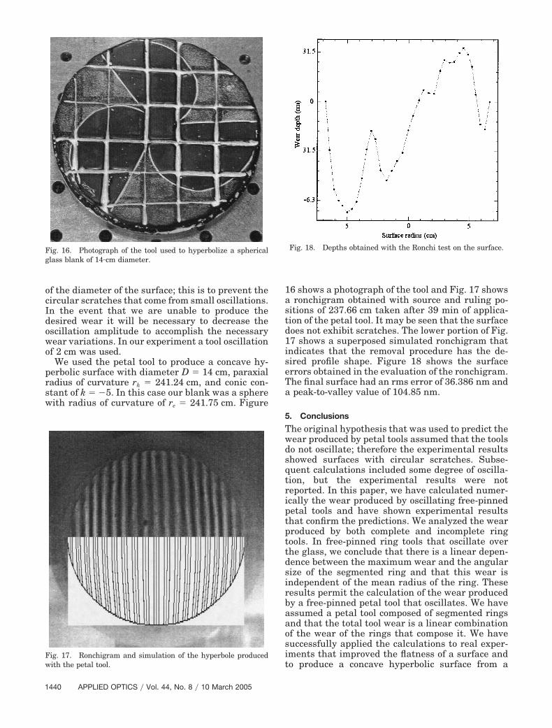
16 shows a photograph of the tool and Fig. 17 showsa ronchigram obtained with source and ruling po-sitions of 237.66 cm taken after 39 min of applica-tion of the petal tool. It may be seen that the surfacedoes not exhibit scratches. The lower portion of Fig.17 shows a superposed simulated ronchigram thatindicates that the removal procedure has the de-sired profile shape. Figure 18 shows the surfaceerrors obtained in the evaluation of the ronchigram.The final surface had an rms error of 36.386 nm anda peak-to-valley value of 104.85 nm.
5. Conclusions
The original hypothesis that was used to predict thewear produced by petal tools assumed that the toolsdo not oscillate; therefore the experimental resultsshowed surfaces with circular scratches. Subse-quent calculations included some degree of oscilla-tion, but the experimental results were notreported. In this paper, we have calculated numer-ically the wear produced by oscillating free-pinnedpetal tools and have shown experimental resultsthat confirm the predictions. We analyzed the wearproduced by both complete and incomplete ringtools. In free-pinned ring tools that oscillate overthe glass, we conclude that there is a linear depen-dence between the maximum wear and the angularsize of the segmented ring and that this wear isindependent of the mean radius of the ring. Theseresults permit the calculation of the wear producedby a free-pinned petal tool that oscillates. We haveassumed a petal tool composed of segmented ringsand that the total tool wear is a linear combinationof the wear of the rings that compose it. We havesuccessfully applied the calculations to real exper-iments that improved the flatness of a surface andto produce a concave hyperbolic surface from a
Fig. 16. Photograph of the tool used to hyperbolize a sphericalglass blank of 14�cm diameter.
Fig. 17. Ronchigram and simulation of the hyperbole producedwith the petal tool.
Fig. 18. Depths obtained with the Ronchi test on the surface.
1440 APPLIED OPTICS � Vol. 44, No. 8 � 10 March 2005

spherical one while we avoid the formation ofscratches in the final surface.
The authors thank David Gale for proofreadingthe manuscript. This paper was partially supportedby Consejo Nacional de Ciencia y Tecnología–Secretaría de Educación Pública (C0NACyT–SEP)2003-C02-44715.
References1. F. W. Preston, “The theory and design of plate glass polishing
machines,” J. Soc. Glass Technol. 11, 214–256 (1927).2. C. C. Dévé, Le travail des Verres d’Optique de Precision, Revue
d’Optique Theorique et Instrumentale, Paris, 1936; translatedby T. L. Tippel as Optical Workshop Principles (Hilger, Lon-don, 1945).
3. M. N. Golovanova, S. S. Kachkin, Ye. I. Krylova, L. S. Tsesnek,and L. I. Shevel’kova, “A method of manufacturing asphericalsurfaces which deviate only slightly from the sphere,” Sov. J.Opt. Technol. 35, 254–256 (1968).
4. Yu. K. Lysyannyy and L. S. Tsesnek, “Computation of thecontour of a mask tool surface for shaping a concave paraboloidof revolution,” Opt. Technol. 40, 446–448 (1973).
5. Yu. K. Lysyannyy, L. S. Tsesnek, L. N. Gurevich, and L. N.Khokhlenkov, “The shaping of optical surfaces by the succes-sively corrected mask method,” Sov. J. Opt. Technol. 44, 226–227 (1977).
6. N. J. Brown, “Axisymmetric aspheric lens figuring for thesmall shop,” Opt. Eng. 15, 424–427 (1976).
7. N. J. Brown, “Computationally directed axisymetric asphericfiguring,” Opt. Eng. 17, 602–620 (1978).
8. R.-S. Chang and P.-Y. Lee, “Computer simulations of looseabrasive grinding aspherical optical surface by local figuring
pitch,” in Advanced Optical Manufacturing and Testing II,V. J. Doherty, ed., Proc. SPIE 1531, 312–317 (1991).
9. S. I. Vinokur XII, “Kinetics of generating plane surfaces,” inGeneration of Optical Surfaces, K. J. Kumamin, ed. (Focal,London, 1962), pp. 365–418.
10. R. González-Castillo, L. Venegas-Pérez, J. González-García, A.Parra-Flores, and A. Cordero-Dávila, “Análisis cinemático deuna máquina pulidora comercial para superficies ópticas,” inProgram of the 46th Congreso Nacional de Física de la SociedadMexicana de Física,” Bull. Soc. Mex. Fis. Suppl. 49, 2 (2003).
11. W. D. Dong, E. S. Putilin, and Y. V. Rudin, “Modeling thevelocity and trajectory of the relative motion of a zone of aworkpiece during surface lapping,” J. Opt. Technol. 70, 573–575 (2003).
12. A. Parra-Flores, A. Cordero-Dávila, J. Cuautle-Cortés, C.Robledo-Sánchez, J. González-García, and V. Cabrera-Peláez,“Simulación de desgastes en el pulido de superficies con laecuación de Preston,” in Program of the 46th Congreso Nacio-nal de Física de la Sociedad Mexicana de Física,” Bull. Soc.Mex. Fis. Suppl. 49, 138 (2003).
13. A. Cordero-Dávila, J. Gonzalez-Garcia, M. Pedrayes-López, L.A. Aguilar-Chiu, J. Cuautle-Cortés, and C. Robledo Sánchez,“Edge effects with the Preston equation for a circular tool andworkpiece,” Appl. Opt. 43, 1250–1254 (2004).
14. M. V. Mantravadi, “Newton, Fizeau, and Haidinger inter-ferometers,” in Optical Shop Testing, D. Malacara, ed. (Wiley,New York, 1992), pp. 1–50.
15. N. R. Draper and H. Smith, Applied Regression Analysis, 3rded., Wiley Series in Probability and Statistics (Wiley, NewYork, 1995), pp. 80–83.
16. A. Bermúdez-López, A. Cordero-Dávila, and J. Cuautle-Cortés,“Diseño para la construcción de Herramienta de Pétalo apli-cada al pulido de superficies ópticas,” in Program of 46th Con-greso Nacional de Física de la Sociedad Mexicana de Física,”Bull. Soc. Mex. Fis. Suppl. 49, 39 (2003).
10 March 2005 � Vol. 44, No. 8 � APPLIED OPTICS 1441